an introduction to stormwater drainage and site development · an approved continuing education...
TRANSCRIPT

An Approved Continuing Education Provider
PDHonline Course C718 (2 PDH)
An Introduction to Stormwater Drainage
and Site Development
J. Paul Guyer, P.E., R.A.
2014
PDH Online | PDH Center
5272 Meadow Estates Drive
Fairfax, VA 22030-6658
Phone & Fax: 703-988-0088
www.PDHonline.org
www.PDHcenter.com
www.PDHcenter.com PDHonline Course C718 www.PDHonline.org
©2014 J. Paul Guyer Page 2 of 23
An Introduction to Stormwater Drainage
and Site Development
J. Paul Guyer, P.E., R.A.
CONTENTS
1. DESIGN CRITERIA
2. ROOF DRAINAGE
3. SURFACE STORM DRAINAGE
4. UNDERGROUND GRAVITY STORM DRAINAGE SYSTEM
5. STORMWATER MANAGEMENT FACILITIES
6. STORMWATER PUMP STATIONS
7. SAFETY AND STORM DRAINAGE SYSTEM COMPONENTS
8. SECURITY AND STORM DRAINAGE SYSTEM COMPONENTS
9. AIRFIELD DRAINAGE
10. SITE DEVELOPMENT
(This publication is adapted from the Unified Facilities Criteria of the
United States government which are in the public domain, are
authorized for unlimited distribution, and are not copyrighted.)
www.PDHcenter.com PDHonline Course C718 www.PDHonline.org
©2014 J. Paul Guyer Page 3 of 23
1. DESIGN CRITERIA.
Design surface drainage, underground drainage systems, stormwater management
facilities, and erosion and sediment control in accordance with the applicable
requirements of the local regulatory authority. The design of the storm drainage
system and stormwater management must address the following:
THE STORMWATER MANAGEMENT PLAN must comply with federal, state,
and local regulatory requirements including regional or site-specific stormwater
management agreements.
THE TEMPORARY AND PERMANENT erosion and sediment control practices
must be provided in accordance with local regulatory requirements during both
the construction and operational phases of the project.
THE GRADING must complement the features and functions of the natural
drainage system and the existing contours. Also consider the high and seasonal
groundwater table elevations in the siting and sizing of stormwater management
facilities.
UTILIZE OVERLAND FLOW and natural site features where stormwater
drainage will not impact site function. Drainage systems must prevent erosion of
existing soils, ponding, and convey flow to a suitable outfall location. Use pump
stations and transmission mains only with explicit authorization by the Owner.
CULVERTS, DITCHES, AND OTHER DRAINAGE STRUCTURES constructed
along or tributary to fish streams must be designed to minimize adverse
environmental effects.
www.PDHcenter.com PDHonline Course C718 www.PDHonline.org
©2014 J. Paul Guyer Page 4 of 23
1.1 DESIGN METHODS. Time of concentration must be calculated using the TR-55
method or as approved the TR-55 Curve Number method. The Rational Method may
also be used for drainage areas smaller than 200 acres. Regional IDF curves are
available in most state or local regulatory agency drainage manuals or from NOAA.
1.2 DESIGN STORM FREQUENCY AND SPREAD. For design of the drainage
system, use a minimum 10-year storm frequency, the facility type minimum, or the
minimum required by the local governing authority, whichever is more stringent.
Maximum spread for many roads is ½ driving lane using a minimum 5-year storm
frequency.
2. ROOF DRAINAGE. Where roof drainage is discharged to grade, provide splash
blocks/paved channels to direct the flow away from the structure. Eliminate safety
hazards from ice, ponding, flooding, etc., in pedestrian and vehicular traffic areas.
Where underground collection of roof drainage is used, provide an air break between
the downspouts and underground piping. Size underground piping in accordance with
the latest edition of the International Plumbing Code (IPC) or minimum 6 inches (150
mm) interior diameter, whichever is greater. No more than three downspouts shall be
collected in a single outlet before connecting to a storm drainage structure, and the
length of pipe from the most distant downspout to a drainage structure shall not
exceed 150 feet (45.7 m). Provide a cleanout for each downspout connection and the
collection header; distances between cleanouts must not be greater than 100 feet;
provide cleanouts at changes in direction.
3. SURFACE STORM DRAINAGE.
3.1 GRADING. Determine the appropriate requirements for site grading and
accessibility. Ensure that the grading and associated stormwater runoff do not
adversely affect surrounding sites. Acceptable ranges of transverse and longitudinal
www.PDHcenter.com PDHonline Course C718 www.PDHonline.org
©2014 J. Paul Guyer Page 5 of 23
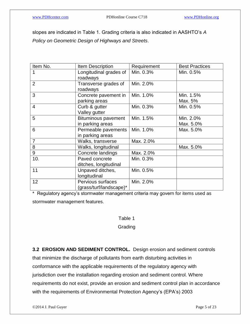
slopes are indicated in Table 1. Grading criteria is also indicated in AASHTO’s A
Policy on Geometric Design of Highways and Streets.
Item No. Item Description Requirement Best Practices
1 Longitudinal grades of roadways
Min. 0.3% Min. 0.5%
2 Transverse grades of roadways
Min. 2.0%
3 Concrete pavement in parking areas
Min. 1.0% Min. 1.5% Max. 5%
4 Curb & gutter Valley gutter
Min. 0.3% Min. 0.5%
5 Bituminous pavement in parking areas
Min. 1.5% Min. 2.0% Max. 5.0%
6 Permeable pavements in parking areas
Min. 1.0% Max. 5.0%
7 Walks, transverse Max. 2.0%
8 Walks, longitudinal Max. 5.0%
9 Concrete landings Max. 2.0%
10. Paved concrete ditches, longitudinal
Min. 0.3%
11 Unpaved ditches, longitudinal
Min. 0.5%
12 Pervious surfaces (grass/turf/landscape)*
Min. 2.0%
* Regulatory agency’s stormwater management criteria may govern for items used as
stormwater management features.
Table 1
Grading
3.2 EROSION AND SEDIMENT CONTROL. Design erosion and sediment controls
that minimize the discharge of pollutants from earth disturbing activities in
conformance with the applicable requirements of the regulatory agency with
jurisdiction over the installation regarding erosion and sediment control. Where
requirements do not exist, provide an erosion and sediment control plan in accordance
with the requirements of Environmental Protection Agency’s (EPA’s) 2003
www.PDHcenter.com PDHonline Course C718 www.PDHonline.org
©2014 J. Paul Guyer Page 6 of 23
Construction General Permit (which is also the referenced standard for LEED
Sustainable Site Prerequisite 1).
4. UNDERGROUND GRAVITY STORM DRAINAGE SYSTEM. For drainage system
design comply with the following criteria.
PROVIDE STRAIGHT ALIGNMENTS for piping between storm drainage
structures. Use of curvilinear alignment is not allowed for pipes with a diameter
of 48 inches (1200 mm) or less. For pipes with a diameter greater than 48
inches (1200 mm) use of curvilinear alignment may be allowed with explicit
authorization by the regulatory authority.. Deflection at structures must not be
less than 90 degrees for main line flows and not less than 60 degrees for
contributory flows, as measured from the centerline of the mainline discharge.
STORM DRAINAGE PIPING must not pass under buildings and must be a
parallel distance of at least 10 feet (3.05 m) from building foundations.
AVOID CONFLICTS with other utilities.
CONFLICT STRUCTURES will not be allowed without Owner approval.
COMPLY WITH STATE OR APPLICABLE REGULATORY AGENCY’S
REQUIREMENTS for separation distances between utilities and other public
health and safety issues.
PROVIDE A STRUCTURE at collection and inlet points, at changes in
horizontal or vertical alignment, at pipe junctions and with minimum spacing of

www.PDHcenter.com PDHonline Course C718 www.PDHonline.org
©2014 J. Paul Guyer Page 7 of 23
a pipe run according to Table 2. Provide a discharge structure wherever flow
changes from piped to open channel flow.
Pipe Diameter Maximum Spacing
Inches mm Feet Meters
12-24 300-600 300 91.44
27-36 675-900 400 121.92
42-54 1050-1350 500 152.4
60 and up 1500 and up 1000 304.8
Table 2
Storm structure spacing criteria
IN THE DESIGN OF CULVERTS and storm drains, consider headwater and
tailwater and their effects on hydraulic grade line and capacity. The following
upstream controls may limit the headwater elevation:
o NOT HIGHER THAN an elevation that is 18 inches (450 mm) below the
outer edge of the shoulder at its lowest point in the grade.
o UPSTREAM PROPERTY DAMAGE.
o ELEVATIONS ESTABLISHED to delineate National Flood Insurance
Program or other floodplain zoning.
o HW/D IS AT LEAST 1.0 and not to exceed 1.5 or the local requirement
where HW is the headwater depth from the culvert inlet invert and D is the
height of the barrel.
www.PDHcenter.com PDHonline Course C718 www.PDHonline.org
©2014 J. Paul Guyer Page 8 of 23
o LOW POINT IN THE ROAD GRADE which is not necessarily at the culvert
location.
o ELEVATION OF TERRAIN and ditches that will permit flow to divert around
the culvert. The tailwater elevation in the storm drain outfall must be either
the average of the critical depth and the height of the storm drain conduit,
(dc + D)/2, or the mean high tide if tidal conditions are present, whichever is
greater. Storm drains must be designed for open channel flow. The
hydraulic grade line for the storm sewer system must not exceed the pipe
crown elevation unless the outfall is submerged. If the controlling tailwater
elevation is above the crown elevation of the outfall, the hydraulic grade line
for the storm sewer system must not exceed one foot (300 mm) above the
crown, or one foot (300 mm) below the structure rim or gutter flow line at
inlets, whichever is the lower elevation at each structure. At structures,
consider setting the inlet pipe crown elevation equal to or greater than the
outlet pipe crown elevation to minimize the hydraulic turbulence at the
junction. Consider setting the invert elevation of the outflow pipe at least 0.1
feet (30 mm) lower than the lowest inflow pipe invert elevation to
accommodate the hydraulic losses through the structure.
o THE DOWNSTREAM PIPE configuration, slope and size must have
capacity for the upstream hydraulic peak flow. The pipe size must not
decrease downstream in the direction of flow.
o LOCATE DRAINAGE STRUCTURES out of paved areas wherever
possible. Adjust structure locations to avoid primary wheel tracks when
structures must be located in roadways.

www.PDHcenter.com PDHonline Course C718 www.PDHonline.org
©2014 J. Paul Guyer Page 9 of 23
o DURING DESIGN evaluate the potential for infiltration of fine soils into
drainage pipe joints and if it is a known maintenance issue at the
Installation, specify watertight joints to mitigate the possibility.
4.1 MINIMUM PIPE SIZE.
Use a minimum inside diameter of 12 inches (300 mm) for storm drainage piping (not
including roof drainage piping) for runs 50 feet (15.2 m) or less and where the existing
downstream pipe is a 12-inch (300 mm) inside diameter with sufficient capacity;
otherwise, use a minimum inside diameter of 15 inches (375 mm).
4.2 MINIMUM AND MAXIMUM COVER.
Provide minimum cover for all pipes sufficient to support imposed dead and live loads
for the pipe materials used, 24 inches (600 mm), ½ of the pipe diameter, or greater
than frost penetration according to UFC 3-301-01, whichever is greater. For pipe in
non-paved areas, account for loads from expected maintenance equipment. Increase
depth of cover, pipe material strength, or bedding requirements to accommodate the
imposed loads during and after construction. For pipe under rigid pavement minimum
cover may be reduced to 12 inches (300 mm) from the top of pipe to the finished grade
and to 6 inches (150 mm) from the top of the pipe to the bottom of concrete pavement
if:
Reinforced concrete pipe (ASTM C76, Class V) is used.
b. Design assumptions and calculations are approved by the Owner
Determine maximum cover for all individual pipe and culvert installations underlying
roads, streets, and open storage areas subject to H-20 live loads. See Chapter 9 of
the FAA document AC 150/5320-5C for additional design guidance on minimum and
maximum cover.
www.PDHcenter.com PDHonline Course C718 www.PDHonline.org
©2014 J. Paul Guyer Page 10 of 23
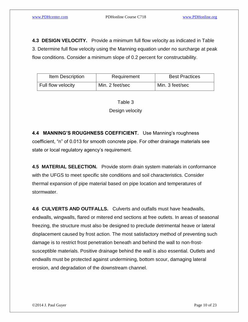
4.3 DESIGN VELOCITY. Provide a minimum full flow velocity as indicated in Table
3. Determine full flow velocity using the Manning equation under no surcharge at peak
flow conditions. Consider a minimum slope of 0.2 percent for constructability.
Item Description Requirement Best Practices
Full flow velocity Min. 2 feet/sec Min. 3 feet/sec
Table 3
Design velocity
4.4 MANNING’S ROUGHNESS COEFFICIENT. Use Manning’s roughness
coefficient, “n” of 0.013 for smooth concrete pipe. For other drainage materials see
state or local regulatory agency’s requirement.
4.5 MATERIAL SELECTION. Provide storm drain system materials in conformance
with the UFGS to meet specific site conditions and soil characteristics. Consider
thermal expansion of pipe material based on pipe location and temperatures of
stormwater.
4.6 CULVERTS AND OUTFALLS. Culverts and outfalls must have headwalls,
endwalls, wingwalls, flared or mitered end sections at free outlets. In areas of seasonal
freezing, the structure must also be designed to preclude detrimental heave or lateral
displacement caused by frost action. The most satisfactory method of preventing such
damage is to restrict frost penetration beneath and behind the wall to non-frost-
susceptible materials. Positive drainage behind the wall is also essential. Outlets and
endwalls must be protected against undermining, bottom scour, damaging lateral
erosion, and degradation of the downstream channel.

www.PDHcenter.com PDHonline Course C718 www.PDHonline.org
©2014 J. Paul Guyer Page 11 of 23
4.7 STORM STRUCTURES. Storm structures for roads and site drainage must be in
accordance with the UFGS, State Department of Transportation’s (DOT) Standards
and Specifications where the project is located or the requirements of the applicable
local regulatory agency that governs stormwater management, whichever is more
stringent. Structures must provide access for maintenance. Internal dimensions must
not be less than 2 feet (600 mm) in any one direction. Ensure that catch basins, curb
inlets, and manholes are of adequate size to accommodate inlet and outlet pipes.
Provide structures of cast-in-place or precast concrete. Masonry structures are
allowed for shallow installations less than 5 feet (1.52 m) in depth. Design structure
frames, covers and grates to withstand traffic loadings and meet any additional
requirements set forth in the using agency criteria for the particular application. Select
grate type based on such factors as hydraulic efficiency, debris handling
characteristics, pedestrian and bicycle safety, and loading conditions. Grates in traffic
areas must be able to withstand traffic loads. Require fixed ladders on all structures
over 12 feet (3.66 m) in depth.
5. STORMWATER MANAGEMENT FACILITIES. Design stormwater management
facilities in accordance with applicable regulations of the regulatory authority.
6. STORMWATER PUMP STATIONS. Use of stormwater pump stations is generally
not allowed except with explicit authorization by the Owner. Design stormwater pump
stations in accordance with the criteria referenced in the paragraph entitled, “Design
Criteria”.
6.1 UPGRADES TO EXISTING PUMP STATIONS. Existing pump stations may be
upgraded where a complete hydraulic analysis shows that the pump station can
operate at the proposed capacity in conformance with the jurisdictional requirements
for a new pump station of equal capacity. Include effects on the existing force main to
its point of discharge in the hydraulic analysis, and if networked, the effects on all other
pump stations connected to the system. This analysis is required whenever additional
www.PDHcenter.com PDHonline Course C718 www.PDHonline.org
©2014 J. Paul Guyer Page 12 of 23
flow is added to a pump station, even if physical changes to the station are not
proposed.
7. SAFETY AND STORM DRAINAGE SYSTEM COMPONENTS. Provide protective
measures for stormwater management facilities, such as detention/retention ponds, in
residential housing areas and other areas frequented by children in accordance with
the applicable requirements of the locality or equivalent. Protective measures include,
but are not limited to appropriate site selection for the storm water management facility
and/or providing a fenced enclosure surrounding the facility. When provided, fence
must be at a minimum 4 feet (1.22 m) high with locking access gates.
8. SECURITY AND STORM DRAINAGE SYSTEM COMPONENTS. Provide
security barriers at all locations where security fences must cross drainage ditches or
swales to ensure that intruders are prevented from passing under the fence. Pipes
larger than 10 inches (250 mm) in diameter that cross under security fences require
protective measures. Designs must comply with appropriate physical security criteria.
9. AIRFIELD DRAINAGE
9.1 DESIGN STORM FREQUENCY AND SPREAD. For design of drainage systems
for airfields and heliports, use the minimum required by the local governing authority
for airfield and heliports or the minimum required as follows, whichever is more
stringent:
Runways and Taxiway Pavements – 2 year storm frequency.
b. Apron Pavements - for 2 year or 5 year storm frequency as directed by the
Owner..
Ponding is not allowed on taxiway and runway pavements including paved shoulders.
Ponding around apron inlets must not exceed 4 inches (100 mm). Center 50 percent of

www.PDHcenter.com PDHonline Course C718 www.PDHonline.org
©2014 J. Paul Guyer Page 13 of 23
runways; center 50 percent of taxiways serving these runways; and helipad surfaces
along the centerline must be free from ponding resulting from storms of a 10-year
frequency.
9.2 SURFACE STORM DRAINAGE FOR AIRFIELDS
9.2.1 GRADING. Use accepted practices for grading criteria for airfields.
9.2.2 CURBS AND GUTTERS. Curbs and gutters are not permitted to interrupt
surface runoff along a taxiway or runway. The runoff must be allowed unimpeded
travel transversely off the runway and then directed to the area inlets. Inlets spaced
throughout the paved apron construction must be placed at proper intervals and in
well-drained depressed locations.
9.2.3 OPEN CHANNELS. Open channels or natural water courses are permitted only
at the periphery of an airfield or heliport facility and must be well removed from the
landing strips and traffic areas.
9.3 UNDERGROUND GRAVITY STORM DRAINAGE SYSTEM FOR AIRFIELDS.
Avoid drainage patterns consisting of closely spaced interior inlets in pavements with
intervening ridges for airfields. Such grading may cause taxiing problems, including
bumping or scraping of wing tanks. Crowned sections are the standard cross sections
for roadways, runways, taxiways, and safety areas. Crowned sections generally slope
each way from the center line of the runway on a transverse grade to the pavement. If
there is a long, gradually sloping swale between a runway and its parallel taxiway (in
which the longitudinal grade, for instance, is all in one direction), additional inlets
should be placed at regular intervals down this swale. Should this be required, ridges
may be provided to protect the area around the inlet, prevent bypassing, and facilitate
the entry of the water into the structure. If the ridge area is within the runway safety
area, the grades and grade changes will need to conform to the limitations established

www.PDHcenter.com PDHonline Course C718 www.PDHonline.org
©2014 J. Paul Guyer Page 14 of 23
for runway safety areas in other pertinent publications. Watertight joints are
recommended under airfield pavements.
9.3.1 MINIMUM AND MAXIMUM COVER. Use cover tables included in Chapter 9 of
FAA document AC 150/5320-5C provided project specific loads and conditions do not
deviate from those indicated.
9.3.2 MATERIAL SELECTION FOR AIRFIELDS. The use of plastic pipe is not
approved for use under any type of airfield pavement except for subsurface water
collection and disposal.
9.3.3 STORM STRUCTURES FOR AIRFIELDS. Design structure frames, covers and
grates to withstand airfield traffic loadings and meet any additional requirements set
forth in the using agency criteria. Isolate airfield structures from the pavement section.
Provide structures of cast-in-place or precast concrete; do not use masonry structures
in airfield construction. Use ductile iron or steel grates and covers. Inlet grating and
frames must be designed to withstand maximum aircraft wheel loads, considering the
gear configuration, of the largest aircraft using or expected to use the facility.
Commercially manufactured grates and frames have been designed specifically for
airport loadings. Provide hold-down devices to prevent grate displacement by aircraft
traffic. If manufactured grates are used, the vendor must certify the design load
capacity. For structures that will be required to support both in-line and directional
traffic lanes such as diagonal taxiways or apron taxi routes, do not consider load
transfer at expansion joints in the design process; however, if specific knowledge
about the long-term load transfer characteristics of a particular feature supports the
use of load transfer in the design of a particular drainage structure, then an exception
can be allowed and load transfer considered.
9.4 SAFETY. Avoid attracting wildlife to the facility; avoid a Bird/Animal Aircraft Strike
Hazard (BASH) issue.
www.PDHcenter.com PDHonline Course C718 www.PDHonline.org
©2014 J. Paul Guyer Page 15 of 23
10. SITE DEVELOPMENT
10.1 PRELIMINARY SITE ANALYSIS. Conduct a preliminary site visit and obtain
photographs of the site. Research and obtain Installation’s master plan, utility maps
and as-built record drawings for information related to topography, utility and storm
drainage availability, including design approaches used in the project vicinity. Evaluate
the potential for abandoned or unmapped utilities. Research and review available
subsurface investigation data and reports in order to evaluate subsurface conditions.
Identify flood hazard areas in accordance with the IBC Section 1612, Flood Loads.
Research and obtain explosive safety requirements. Consult with the regulatory
authorities to determine if the site has environmental concerns, such as radon,
pesticides, or known contamination. If required, provide radon mitigation system
design. Evaluate the need for additional analysis based on project requirements and
site conditions. Conduct detailed consultations with the regulatory authority in order
to clearly define requirements and preferences.
10.2 EXISTING CONDITIONS
10.2.1 GEOTECHNICAL SITE INVESTIGATION. Obtain soil exploration, testing and
evaluation from a professional geotechnical engineer. Determine the extent of
exploration and testing based on recommendations with the geotechnical engineer,
structural engineer (for foundations), civil engineer (for LID, pavements, wells, septic
systems, etc.), local stormwater permitting agency (for detention ponds), and
regulatory authority reviewers. Indicate the results of the subsurface investigation,
including boring locations, boring logs, groundwater observations, a summary of
laboratory test results, and any details required to convey requirements for site
preparation on the contract documents.
10.2.2 SURVEYING. A licensed or certified professional must seal all surveys in
accordance with the applicable requirements of the local regulatory agency or
overseas equivalent having jurisdiction over the installation. Where overseas
www.PDHcenter.com PDHonline Course C718 www.PDHonline.org
©2014 J. Paul Guyer Page 16 of 23
equivalent requirements do not include an accuracy standard, provide surveys at a
minimum third order in accordance with the Federal Geodetic Control Committee’s
Standards and Specifications for Geodetic Control Networks. Consult with the owner
to establish contact with the owner’s real estate personnel prior to entering property.
Notify and obtain authorization from all public and private landowners for a right of
entry and trespass, over, across and through all lands necessary to perform required
field survey work. Consult with owner to establish contact with the appropriate
environmental personnel before entering the area with regards to any restrictions
concerning vegetation cutting/clearing, natural resources, endangered species, etc.
10.2.2.1 TOPOGRAPHIC SURVEYS. Provide a topographic survey of the project site
in accordance with each service’s requirements as well as the requirements of the
state or local authority in which the site is located. If state or Host nation equivalent
requirements are not available, use the National Society of Professional Surveyors
(NSPS) Model Standards for Topographic Surveys.
10.3 DESIGN APPROVALS AND PERMITS. The owner must identify, assist and
provide, as applicable, all permits, approvals and fees required for the design and
construction of the proposed project from federal, state and local regulatory authorities
or overseas equivalent. A Professional Civil Engineer experienced and licensed in the
state where the project is located may be required to obtain permits and approvals.
Seek out the project NEPA documentation, as applicable, for project specific
requirements. Consult with the owner to determine the appropriate signatories for
permit applications.
10.4 CLEARING AND DEMOLITION. Identify the following in the construction
documents: limits of disturbance; limits of demolition; limits of clearing and grubbing;
isolated trees and shrubs to remain or to be removed. Describe size, density and type
of trees to be cleared and grubbed, items to be salvaged or relocated, staging area,
temporary storage area and location. Coordinate with the owner concerning clearing
options to remove merchantable timber from the project site. During site demolition

www.PDHcenter.com PDHonline Course C718 www.PDHonline.org
©2014 J. Paul Guyer Page 17 of 23
and preparation, remove existing and abandoned utilities under or within 10 feet (3.05
m) of the proposed buildings and facilities foundations; reroute existing utilities to
remain.
10.5 SITE DEVELOPMENT. Base location and orientation of facilities on an analysis
of activities to be accommodated and on specific requirements for each project, to
include all functional, technical and economic factors. Incorporate the following into
site design, as applicable:
10.5.1 LAND USE (existing and future)
10.5.2 CIRCULATION (vehicle and pedestrian)
10.5.3 ORIENTATION AND LOCATION TO INTEGRATE GREEN SPACE. Provide
adequate grading and drainage while preserving natural topographic features to
minimize cut and fill, impact on existing drainage patterns and tree removal.
10.5.4 OPERATIONAL AND NATURAL CONSTRAINTS
10.5.4.1 MAINTAIN MANDATED BUFFERS:
Noise abatement.
Antiterrorism/physical security clearances.
Storage and handling hazardous material clearances.
Separation of incompatible land use or functions.
Building setbacks (if established).
Fire separation zones per building and fire codes.

www.PDHcenter.com PDHonline Course C718 www.PDHonline.org
©2014 J. Paul Guyer Page 18 of 23
10.5.4.2 ELIMINATE OR MINIMIZE CONSTRUCTION ACTIVITIES REQUIRING
PERMITS, for areas such as archaeological sites, wetlands, utilities, and stormwater
management.
10.5.4.3 MINIMIZE SITE OR UTILITY MAINTENANCE AND OPERATING COSTS.
10.5.4.4 ACCOMMODATE SITE constructability and security requirements.
10.5.4.5 MINIMIZE DISTANCE to existing utility connections.
10.5.5 FLOOD HAZARD AREAS. Project sites located in flood hazard areas must be
designed in accordance with IBC 1612. Ensure proper correlation between vertical
datums.
10.6.2 VEHICLE CIRCULATION.
For design of streets and parking for facilities, comply with American Association of
State Highway and Transportation Officials’ (AASHTO’s) A Policy on Geometric
Design of Highways and Streets; and AASHTO’s Roadside Design Guide. Design
streets and parking areas (i.e., site entrances and exits, service drives, parking lots
and other areas with special requirements (e.g., drive up drop off areas or loading
docks)) to accommodate the largest vehicle that will use the facility. The design must
also address the turning and reverse movements for the vehicles using the facility.
Streets, parking areas and structures must conform to current antiterrorism and
handicap accessibility requirements. Use Best Practices document, AASHTO’s
Guidelines for Geometric Design of Very Low-Volume Local Roads (ADT ≤ 400) as
applicable.
10.6.2.1 TRAFFIC STUDIES. Provide traffic studies and analysis in accordance with
SDDCTEA’s Pamphlet 55-17 which references SDDCTEA’s Pamphlet 55-8, Traffic
Engineering Study Reference.
www.PDHcenter.com PDHonline Course C718 www.PDHonline.org
©2014 J. Paul Guyer Page 19 of 23
10.6.2.2 DESIGN VEHICLES. Design vehicle types include:
a. Passenger car, truck, light-delivery truck, bus, and truck combinations are as
defined by AASHTO (e.g., moving vans, refuse trucks and school buses, snow-
clearing trucks)
b. Emergency vehicles
c. Specialized military vehicles, such as tracked vehicles
Obtain design information for emergency vehicles and specialized military vehicles
from the Government’s Project Manager.
10.6.2.3 DESIGN TRAFFIC. Use the Transportation Research Board’s (TRB’s)
Highway Capacity Manual to evaluate average daily traffic (ADT) and peak hourly
traffic, as applicable. Adjust for vehicles other than passenger cars. In addition to the
vehicles indicated in the Highway Capacity Manual (e.g., trucks, RV’s and buses), add
specialized military vehicles as a vehicle type and determine the nearest equivalent
AASHTO vehicle type.
10.6.2.4 STREETS AND ROADWAYS. Single-lane streets may be provided for fire
lanes and approach drives to buildings within built-up areas. Access roads to
unmanned facilities may also be single-lane roads. Where shoulders are not
sufficiently stable to permit all-weather use and the distance between intersections is
greater than ½-mile (805 m), turnouts must be provided at 1/4-mile (402 m) intervals
along single lane roads for use by occasional passing or meeting vehicles.
10.6.2.4.1 FIRE LANE AND EMERGENCY VEHICLE ACCESS. Fire lanes and
emergency vehicle access must comply with requirements of the regulatory authority.

www.PDHcenter.com PDHonline Course C718 www.PDHonline.org
©2014 J. Paul Guyer Page 20 of 23
10.6.2.5 PARKING AREAS. Parking areas include on-street parking, off-street
parking lots, and parking structures. Conform to existing topography to the greatest
extent possible. Refer to scope of work for total parking requirement of number of
spaces. Provide parking spaces primarily by off-street parking areas or structures.
Design parking areas in accordance with SDDCTEA Pamphlet 55-17 Better Military
Traffic Engineering, Chapter 17. The design must allow for all types of traffic that may
be associated with the facility, including deliveries, emergencies and garbage pick-up.
However, the design must discourage through traffic.
10.6.2.5.1 ON-STREET PARKING. The use of on-street parking is discouraged. On-
street parking will not be allowed within 20 feet (6.10 m) of an intersection. The
minimum length for the first and last stall is 18 feet (5.49 m). The minimum length for
each interior stall is 22 feet (6.71 m). Exception to SDDCTEA Pamphlet 55-17: The
minimum width for all stalls is 8 feet (2.44 m).
10.6.2.5.2 OFF-STREET PARKING. Typically 90 degree parking is preferred for off-
street parking for ease of traffic flow. If 90 degree parking is not used, the designer
must be able to justify by showing that the minimum functional and technical
requirements are met while providing an economic benefit. Provide minimum 9 feet
(2.74 m) wide and 18.5 feet (5.64 m) long parking spaces for 90 degree parking.
Exception to SDDCTEA Pamphlet 55-17: In areas of limited space, provide a minimum
buffer strip of 8 feet (2.44 m).
10.6.2.5.3 MOTORCYCLE PARKING. Motorcycle parking surfaces are typically
designed as rigid pavements to prevent kickstands from penetrating bituminous
pavement in warm weather. Motorcycle parking stalls will be a minimum of 9 feet (2.74
m) long and 4.5 feet (1.37 m) wide.
10.6.3 BRIDGES AND UNDERPASSES. Where applicable, comply with AASHTO’s
A Policy on Geometric Design of Highways and Streets and AASHTO’s Standard
Specifications for Highway Bridges. Use Best Practices document, U.S. Department of
www.PDHcenter.com PDHonline Course C718 www.PDHonline.org
©2014 J. Paul Guyer Page 21 of 23
Agriculture’s (USDA’s) Low-Water Crossings: Geomorphic, Biological, and
Engineering Design Considerations as applicable. For railroad bridges comply also
with the American Railway Engineering and Maintenance-of-Way Association
(AREMA) publication Manual for Railway Engineering as well as the design manual of
the relevant railroad company.
10.6.4 SPECIAL CIRCULATION AREAS. Circulation areas for other than normal
passenger car traffic have special requirements to maintain traffic safety. These areas
require additional space to accommodate unusual traffic patterns and greater turning
radii for maneuverability. Special circulation areas include areas such as drop off
areas, delivery and service zones, dumpsters, drive-in facilities, emergency vehicle
access, and entry control facilities.
10.6.4.1 ENTRY CONTROL FACILITIES. Use SDDCTEA Pamphlet 55-15, Traffic
and Safety Engineering for Better Entry Control Facilities for entry control facility
criteria.
10.7 SITE APPURTENANCES. Provide site appurtenances in accordance with
State or local standards where project is located.
10.7.1 PEDESTRIAN CIRCULATION. Provide a network of sidewalks, separated
from, but connected to vehicular circulation systems, to allow for pedestrian circulation
between various new and existing elements of the project. Interface new pedestrian
circulation systems with existing pedestrian circulation systems. Provide crosswalks
for pedestrian safety as indicated in SDDCTEA’s Pamphlet 55-17, Chapter 8. The
minimum width for walks is 4 feet (1.22 m). Use Best Practices document, AASHTO’s
Guide for the Planning, Design and Operation of Pedestrian Facilities for additional
design guidance. Sidewalks may consist of portland cement concrete (PCC),
bituminous concrete (asphalt), solid pavers, permeable pavers, or pervious concrete.
The minimum thickness of PCC concrete sidewalks is 4 inches (100 mm). Provide

www.PDHcenter.com PDHonline Course C718 www.PDHonline.org
©2014 J. Paul Guyer Page 22 of 23
bituminous sidewalks with a minimum 4 inches (102 mm) thick base and a 1 inch (25
mm) thick bituminous surfacing.
10.7.2 CURB/CURB AND GUTTER. Use concrete curb and gutter when overland
flow cannot be achieved; to extend curb/curb and gutter from an adjacent facility; or to
confine traffic. Asphalt-type curbs are only allowed in remote areas where approved by
the Installation.
10.7.3 WHEELSTOPS. Provide 6 feet (1.83 m) long wheelstops anchored to the
pavement at parking spaces adjacent to sidewalks, buildings, stormwater
management facilities, areas of extreme slope, and other areas without curb where a
vehicle would likely cause property damage. Locate the front face of the wheelstop 30
inches (762 mm) from the edge of the pavement or sidewalk. Where snow removal
equipment is used, wheelstops may not be allowed by the regulatory authority.
10.7.4 BOLLARDS.
10.7.4.1 BOLLARDS AROUND STRUCTURES. Provide bollards around any
structures subject to damage from vehicular traffic by incidental contact; such bollards
must be at minimum 4 feet (1.22 m) high. For steel bollards, provide minimum 4 inch
(100 mm) diameter filled with concrete and painted. Bollards on aircraft aprons
protecting fire hydrants may not exceed 30 inches (762 mm) aboveground and 24
inches (610 mm) above load bearing paving.
10.7.5 SIGNAGE AND MARKINGS. Provide signs and associated pavement
markings to facilitate proper utilization of the project site. Provide new traffic control
devices (i.e. signs, markings, etc.) in accordance with SDDCTEA’s Pamphlet 55-17
Better Military Traffic Engineering and Pamphlet 55-14, Traffic Engineering for Better
Signs and Markings. Also use Federal Highway Administration’s (FHWA’s) Manual on
Uniform Traffic Control Devices (MUTCD) and Standard Highway Signs and Markings
(SHSM).

www.PDHcenter.com PDHonline Course C718 www.PDHonline.org
©2014 J. Paul Guyer Page 23 of 23
Provide non-reflectorized pavement markings for paved parking areas, reflectorized
pavement markings for paved roads and streets, and fire access markings in
accordance with State DOT or local governing authority’s requirements.
10.7.6 TRASH DUMPSTER ENCLOSURES. Where dumpster pads are required in a
project, provide a dumpster pad with an enclosure conforming to the Installation
Appearance Plan. Provide a concrete pavement pad to support and accommodate
the dumpster(s) and front wheels of the service truck.
10.8 UTILITIES. Locate utilities to minimize connection costs. New underground
utilities must be at least 10 feet (3.05 m) from proposed structures, except for building
connections. Minimize underground utilities located beneath pavements, except where
crossings are required. Locate required crossings to minimize traffic interference with
future maintenance. Obstructions including signs and poles for overhead utilities
must be located outside the limits of usable shoulder on roads designed without barrier
curbs. Where practicable, roads designed with barrier curbs must have the desirable
lateral clearances to obstructions as indicated in AASHTO’s, A Policy on Geometric
Design of Highways and Streets except that fire hydrant clearances must be in
accordance with requirements of the regulatory authority.