an intelligent assistant for conceptual design -
TRANSCRIPT

JS Gero (ed), Design Computing and Cognition'04, 3-22.© 2004 Kluwer Academic Publishers, Dordrecht, Printed in the Netherlands
AN INTELLIGENT ASSISTANT FOR CONCEPTUAL DESIGN
Informed Search Using a Mapping of Abstract Qualities to Physical Form
KIMBERLE KOILEMassachusetts Institute of Technology, USA
Abstract. In early stages of design, the language used is often veryabstract. In architectural design, for example, architects and theirclients use experiential terms such as “private” or “open” to describespaces. The Architect’s Collaborator (TAC) is a prototype designassistant that supports iterative design refinement using abstract,experiential terms. TAC explores the space of possible designs insearch of solutions satisfying specified abstract goals by employing astrategy we call dependency-directed redesign: It evaluates a designwith respect to a set of goals, uses an explanation of the evaluation toguide proposal and refinement of design repair suggestions, thencarries out the repair suggestions to create new designs.
1. Introduction
In early stages of design, the language used is often very abstract. Engineersmight talk about designing a piece of equipment that is “easy to maintain”.Clothing designers talk of “baggy” clothing. Architects and their clients useexperiential terms such as “private” and “open”. Throughout the designprocess these abstract terms are operationalized and translated into physicalcharacteristics of the artifact being designed. The design process can beviewed as one of exploration, trying to turn goals, often articulated only invery abstract terms at the beginning of the process, into an artifact thatrealizes those goals.
If we are to build programs that help designers during the early stages ofdesign, often termed conceptual design, we must give those programs richvocabularies and the capability to represent and reason with abstractconcepts. The hypothesis put forth in this paper is the following:Computational tools can support conceptual design by providing a mappingof abstract terms to measurable design features and by using that mapping inan informed, exploratory search of a design space. The Architect’s
2 K. KOILE
Collaborator (TAC) is a prototype design support system that illustratesthese ideas in the domain of architecture. TAC employs techniques fromartificial intelligence to explore a space of designs using a technique we calldependency-directed redesign. TAC is an intelligent design assistant thatfocuses on design refinement using abstract terms, leaving to the designerthe tasks of providing a starting design, specifying and respecifying goals,and ranking designs.
This paper begins by describing a design problem that TAC solved, thendiscusses how TAC works and gives results from an experiment with aFrank Lloyd Wright Prairie house and from a real-world design example.The paper then discusses related work, future work, and contributions.
2. An Architectural Example
Architectural design is well-suited to research on conceptual design forseveral reasons. Most design problems exhibit the difficulties mentionedearlier: They are exploratory in nature and involve the use of termsrepresenting abstract, experiential qualities. Such experientialqualities—e.g., openness, spaciousness, privacy—are not easily articulatedor formalized. Yet they are an essential part of the architectural designprocess: Architects and their clients often describe desired spaces in terms ofthese qualities; architects use their knowledge from past experiences, fromenvironment behavior research, and from their own theories to createphysical form that manifests such qualities. This knowledge can bearticulated and structured as general design knowledge (e.g., Wright 1954;Alexander et al. 1977; Zeisel and Welch 1981; Hertzberger 1993). Asillustrated in this paper, this design knowledge can be operationalized andused as the basis for a conceptual design support system that reasons aboutabstract qualities and physical form.
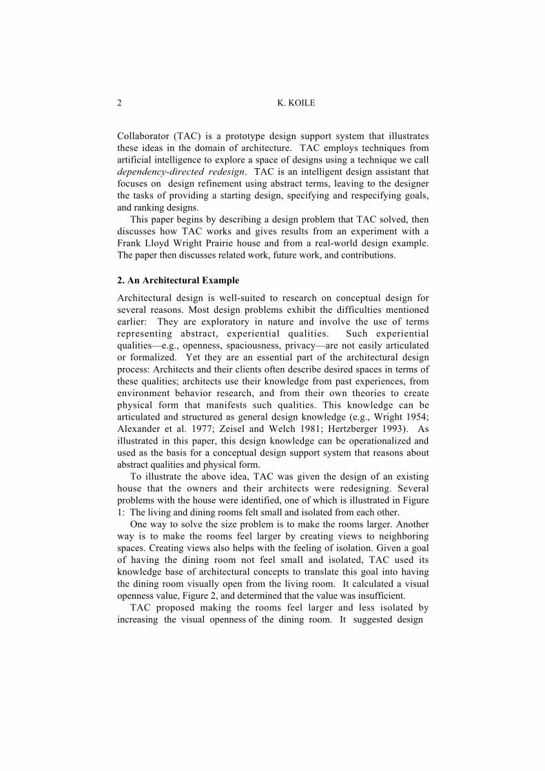
To illustrate the above idea, TAC was given the design of an existinghouse that the owners and their architects were redesigning. Severalproblems with the house were identified, one of which is illustrated in Figure1: The living and dining rooms felt small and isolated from each other.
One way to solve the size problem is to make the rooms larger. Anotherway is to make the rooms feel larger by creating views to neighboringspaces. Creating views also helps with the feeling of isolation. Given a goalof having the dining room not feel small and isolated, TAC used itsknowledge base of architectural concepts to translate this goal into havingthe dining room visually open from the living room. It calculated a visualopenness value, Figure 2, and determined that the value was insufficient.
TAC proposed making the rooms feel larger and less isolated byincreasing the visual openness of the dining room. It suggested design

AN INTELLIGENT ASSISTANT FOR CONCEPTUAL DESIGN 3
Figure 1. A view from living room to dining Figure 2. Floor plan showing visual
openness of dining from viewpoint *; value is 0.42. Shaded region is visible. Dotted lines are open edges.
modifications to achieve this increase, and created seven new designs by:rotating the stair 90 degrees, rotating the stair 270 degrees, moving the stairto three different exterior edges, removing the stair, replacing the stair wallwith a screen. The last solution, with the stair wall “screenified”, wasimplemented by the owners, Figures 3 and 4.
Chatham#2*
Liv ing Dining
Screenify Stair
Figure 3. A view from living to dining with Figure 4. TAC’s solution with screen screen in place of wall New visual openness value is 0.61.
TAC creates new designs with a visually-open dining room by using amapping between abstract qualities and operators on physical form, Figure 5.It locates the function that relates visually-open to visual openness, and findsthat one territory is visually open to another if at least .6 of its area is visible.Finding this not true, TAC uses a general rule about making an expression ofthe form “x greater than y” true by increasing y, and proposes increasingvisual openness (the value of y in this case). It then finds in its knowledgebase techniques for increasing visual openness by modifying the thingsblocking the view. It determines that the stair blocks the view, then applieseach of the techniques to the original design, producing the new designs.

4 K. KOILE
Figure 5. Portion of TAC’s mapping of abstract terms to operators on physical form
This example illustrates TAC’s behavior: It translates a goal stated interms of abstract qualities into operators on physical form. It performs thistranslation using a hierarchy that maps abstract terms to physicallymeasurable design characteristics and design operators for achieving thosecharacteristics. It methodically searches the space of possible solutions bysuggesting modifications to the design, pruning suggestions when possibleso that it generates only new designs with a good chance of satisfying thedesired goal. This informed search of a design space is performed using atechnique we call dependency-directed redesign. TAC’s intelligence thusderives from two aspects: its hierarchy that maps abstract terms to operatorson physical form, and its dependency-directed redesign strategy.
3. Hierarchy: Mapping Abstract Terms to Physical Terms
As mentioned, part of TAC’s intelligence derives from its mapping ofabstract qualities to details of physical form. TAC knows, for example, thatit can make one space more visible from another by removing interveningwalls. It knows that it can make a space feel more private by making less ofit visible or by making the path to it from a front door less direct. TAC alsoknows about characteristics of Frank Lloyd Wright’s Prairie houses.
TAC represents architectural knowledge—general knowledge as well as adesigner’s or client’s particular preferences—using constructs called designcharacteristics. TAC also contains domain-independent knowledge fromgeometry, arithmetic, logic, and computation, which it represents using whatwe call TAC- func t ions . The following sections describe TAC’srepresentation for designs, design characteristics, and TAC-functions, andillustrate how these constructs are used to map abstract qualities to details ofphysical form.
Visual openness of Dining from Living greater than .6
Dining visually open from Living
functional definition
rotate elements blocking the viewmove elements blocking the viewremove elements blocking the viewscreenify elements blocking the viewpuncture elements blocking the view
ways to increaseways to decrease
… increase xdecrease yset xset y
ways to change x greater-than y to be true

AN INTELLIGENT ASSISTANT FOR CONCEPTUAL DESIGN 5
3.1. REPRESENTING DESIGNS
TAC represents a design as a set of five models, each capturing a differentaspect of a design. The design element model contains size and locationinformation for walls, windows, etc.; it can be thought of as a primitivecomputer-aided design (CAD) model. The edge model is a two-dimensionalgeometric abstraction of the design element model, containing points andnon-overlapping edges. Edges are either one-dimensional abstractions ofdesign elements (e.g., walls), or one-dimensional projections of designelements. Projections, also called projected edges, are “invisible” edges thatextend in a parallel or perpendicular direction from design element edgesand help bound two-dimensional regions we call territories (Kincaid 1997).Territories are grouped into a territory model, another geometric abstractionof a design element model. (See Figures 2 and 4 for examples.) A use spacemodel pairs territories with uses specified by the designer. Finally, acirculation model is a graph representing paths between doorways.1
TAC’s representation for a design differs from most other representationsof architectural designs in three significant ways. First, the fundamentalvocabulary is that of design elements—walls, windows, etc. Most otherknowledge-based architectural design systems that generate new designsrepresent only spaces, and thus cannot reason about physical form. Second,territories, often called spaces in other systems, are derived from the designelements, not specified independently. Finally, most other systems do nothave separate representations for territories and use. A notable exception is(Simoff and Maher 1998). Representing use separately from territoriesenables TAC to reason about physical form independently of intended use.
3.2. DEFINING DESIGN CHARACTERISTICS
As mentioned above, design characteristics represent architectural propertiesof a design, including such concepts as visual openness, physicalaccessibility, and floor plan area. Some design characteristics can becomputed directly from design elements, while others are derived fromcomputed design characteristics and are related to physical form via thosecharacteristics. Design characteristics form a decomposition hierarchy, withcharacteristics computed from physical form at the bottom and those derivedfrom them higher up. In this way experiential qualities are mapped intodetails of physical form. Four design characteristics, which appear inexamples throughout this paper, illustrate this mapping. The decompositionhierarchy for these characteristics is shown at the end of this section.
1 Design elements and their edges are entered by hand using a 2D design editor; projectededges, territories, and circulation paths are computed automatically. Visualization capabilitiesmore sophisticated than 2D floor plans are possible, but are outside the scope of this research,which is focused on intelligent exploration of design space.

6 K. KOILE
Example 1: Visual-openness is quantitative and measures the portion of aterritory visible from another territory. Visual-openness is an example of adesign characteristic that is computed from physical form elements; itsevaluation function is a “black box” computational geometry routine.Figures 2 and 4 show the results of visual-openness calculations.
Example 2: Visually-open is boolean-valued and defined in terms ofvisual-openness by using a threshold: A territory is considered visually-openfrom another territory if at least 0.6 of its area is visible from the otherterritory. Visually-open is an example of a derived design characteristic. Itsevaluation function is defined in terms of visual-openness using a Lisp-likeexpression: (gt (visual-openness x from y) 0.6).
Example 3: Perceived-main-entryness is vector-valued and gives ameasure of the perception of an exterior door as a main entry. Characteristicsthat influence a visitor’s choice of door when approaching a house arecomponents of perceived-main-entryness. These include distance betweendoor and street, straightness of path between door and street, and formalityof door. Perceived-main-entryness is a derived characteristic; its evaluationfunction collects all components into a vector. Perceived-main-entrynessalso has necessary conditions: In order to have a perceived-main-entrynessvalue, for example, an exterior door must be visible from the street.
Example 4: The design characteristic perceived-main-entry is defined interms of perceived-main-entryness. Its value is the exterior door most likelyto be perceived as the main entry. TAC constructs a partial order that ranksexterior doors by their perceived-main-entryness values, and returns the topof the partial order as the value of perceived-main-entry. Alternatively, theevaluation function for perceived-main-entry could combine the componentsof the perceived-main-entryness vector into a single value and choose thedoor with the highest value. Notice, however, that the components areincommensurate, and it is not necessarily meaningful, nor obvious how tocombine them into a single value.
These examples of design characteristics illustrate TAC’s decompositionhierarchy of characteristics. The means by which a design characteristic’sevaluation function is defined determines the characteristic’s place in thehierarchy. A characteristic that is considered to be directly related tophysical form is at the bottom of the hierarchy and has an evaluationfunction that is a predefined “black box” that operates on one or moremodels representing a design. A derived design characteristic is higher up inthe hierarchy and has an evaluation function constructed using one of threedifferent methods: evaluation function body (e.g., as visually-open),components, or components and necessary conditions (e.g., as perceived-main-entryness). These methods provide the means for constructing thehierarchy, as shown in Figure 6.

AN INTELLIGENT ASSISTANT FOR CONCEPTUAL DESIGN 7
visually-open
visual-openness
visible-from
privacy
distance-btwchange-in-direction-btw
components
physical-accessibility formality-of-entry
perceived-main-entryness
degree-of-hingesolidity
components
built-exterior-pathscomponents
componentsnecessary conditions
perceived-main-entry
evaluation function body
evaluation function body
Figure 6. Dependency links for some of TAC’s design characteristics
3.3. COMPLETENESS
TAC’s knowledge base is complete enough to solve interesting, simple two-dimensional redesign problems, as with the Chatham house design problemsdescribed in sections 2 and 5. It contains 30 TAC-functions which representarithmetic relations, logical relations, computational constructs, and setconcepts. These TAC-functions form a basic set of domain independentfunctions out of which new design characteristics can be built for otherarchitectural design problems. The remaining ten TAC-functions representgeometric concepts, e.g., distance between two things. More geometricconcepts could be added, e.g., alignment, overlap (Cui and Randell 1992).
TAC contains 62 design characteristics, which represent architecturalconcepts such as privacy, visual openness, paths between two designelements. Forty of these proved sufficient for the Chatham design problems.The remaining 22 characteristics were added for a Frank Lloyd WrightPrairie house experiment and included Wright-specific characteristics suchas circuitous path, place of prospect, and place of refuge (Hildebrand 1991).More design characteristics could be added easily for design problemsinvolving other architectural types or other architects.
4. Dependency-Directed Redesign
As mentioned earlier, TAC’s intelligence derives from its designcharacteristic hierarchy, which maps abstract concepts to details of physicalform, and from its informed search using that hierarchy. Its informed searchemploys a technique we call dependency-directed redesign, which isinspired by artificial intelligence work on dependency-directed backtracking(Stallman and Sussman 1977), plan repair (Sussman 1975, Simmons 1992),and abstraction in search (Sacerdoti 1974). From dependency-directedbacktracking, TAC borrows the idea of using an explanation of goal failureto guide search for a solution. From plan repair, TAC borrows the idea of

8 K. KOILE
searching to find an intermediate state in which some goals are satisfied,then repairing that state to satisfy remaining goals. From abstraction insearch, TAC borrows the idea of limiting search in a very large solutionspace by searching in a smaller space: TAC searches in what we call repairsuggestion space rather than in design space. Combining these three ideas,TAS uses an explanation to prune repair suggestion space, proposing onlythose repairs that have a good chance of leading to solutions, and thusdecreasing the number and improving the relevance of new designs.
4.1. FROM EXPLANATION TO REPAIR SUGGESTIONS
Dependency-directed redesign uses an explanation of goal failure and aknowledge base of repair strategies to propose suggestions for modifying adesign: Given an initial design and a set of goals, TAC evaluates a designwith respect to the goals and uses the resulting explanation to propose repairsuggestions for any goals not satisfied. It then prunes and refinessuggestions, and creates new designs for the remaining suggestions.
Returning to the Chatham house prior to remodeling (Figures 1 and 2),consider the goal of having the dining room visually open from the livingroom. The goal is represented by the expression (visually-open Dining fromLiving). TAC evaluates this goal, determines that it is not satisfied, andproduces an explanation of the failure in the form of a tree that represents atrace of the goal expression’s evaluation, Figure 7. By walking down thetree, TAC can determine why a goal was not satisfied and then use thatinformation to propose suggestions for design repair.
(visually-open Dining from Living) value: false
(gt (visual-openness Dining from Living) 0.6) value: false
(gt 0.42 0.6) value: false
(visual-openness of Dining from Living) value: 0.42
substitute evaluation function body
reduce expression
explanation
Figure 7. Explanation for (visually-open Dining from Living) for Chatham example
In particular, TAC identifies opportunities to repair the cause of failureby looking for expressions whose value it knows how to change viadomain independent routines called fixers. Fixers reason about how to getfrom a current value to a desired value; they propose increasing, decreasing,or setting values. They rely on a characteristic’s increasers, decreasers, and

AN INTELLIGENT ASSISTANT FOR CONCEPTUAL DESIGN 9
setters—expressions that when evaluated modify a design, therebychanging the value of the characteristic. (Examples of fixers and increaserswere shown in Figure 5, labeled as “ways to change …” and “ways toincrease”, respectively.) Whether a design characteristic or TAC-functionhas a fixer, increasers, decreasers, or setters depends on the nature of thecharacteristic or function. Some characteristics, such as the color of a designelement, are directly settable and have setters that change a value. Others,such as visual-openness, are not directly settable, and hence do not havesetters; instead their values are changed by modifying the design. Thus,instead of setters, the characteristic visual-openness has increasers, sincecertain modification operators, e.g., removing an intervening design element,have a good chance of increasing its value.
To repair the Chatham design so that the dining room is visually openfrom the living room, TAC traverses the explanation shown in Figure 7 untilit finds methods for “fixing” a node’s expression. When it gets to the gtnode, it finds that it knows how to fix a (gt x y) expression: it can set y to begreater than x, decrease y to be less than x, set x to be greater than y, orincrease x to be greater than y. In the current expression, y is a constant, 0.6.,and cannot be decreased or set; x is the visual-openness expression, andvisual-openness cannot be directly set. One option remains: increasing x.TAC checks its knowledge base and finds that it knows how to increase thevalue of visual-openness by means of increasers associated with thatcharacteristic. So it proposes increasing the value of visual-openness:
(increase-value of (visual-openness Dining from Living)
until visual-openness greater than 0.6)
TAC then retrieves increasers (see Figure 5), which are written in termsof operators on design elements that block the view between things, e.g.,
(remove blocking-elts-btw x y) (screenify blocking-elts-btw x y)
Substituting arguments of Dining and Living from the original goalexpression, TAC then proposes specific repair suggestions, e.g.,
(remove blocking-elts-btw Dining Living) (screenify blocking-elts-btw Dining Living)
TAC now checks the design to identify design elements that block the view,finds the stair, substitutes it into the repair expressions, and proposes, e.g.,
(remove Stair) (screenify Stair)
For each suggestion, TAC then creates new designs, one of which wasshown in Figure 4.
4.2. FROM REPAIR SUGGESTIONS FOR GOALS TO NEW DESIGNS
The Chatham house example illustrates how TAC works with a single goal,translating a goal expression into operators on physical form, carrying outthose operators to create new designs. More realistic design problems havemultiple, often conflicting goals. TAC deals with this situation by using a

10 K. KOILE
generate-and-test control structure, generating intermediate designs thatsatisfy a subset of the goals, then iteratively repairing those designs to satisfyremaining goals. An enabling assumption for this approach is that somegoals will be independent, so that working on one goal does not always undoa previously satisfied goal (Sussman 1975). For the goals that do interact,some amount of work to reevaluate and resatisfy goals is necessary. TAClimits the amount of work in two ways. First, as previously described, itseparates the proposing of repairs from the performing of repairs, therebyenabling it to avoid designs that it knows will not satisfy goals. Second, itsgenerate-and-test control structure includes a lookahead step: Whenproposing repair suggestions for a particular goal, it “looks ahead” forpotential goal interactions. It looks both for conflict, i.e., when satisfying agoal will undo an already satisfied goal, and synergy, i.e., when amodification will satisfy more than one goal. Three kinds of conflict andsynergy were identified: obvious, predictable, unpredictable. TAC handlesthe first two of these: Obvious interactions are detected by comparing goals,predictable interactions are detected by comparing repair suggestions forgoals. Being able to reason about obvious and predictable interactionsenables pruning of repair suggestions before creating designs, which helpscontrol search and increases the chances that intermediate designs are closerto solutions. Unpredictable interactions, by definition, cannot be detectedahead of time, and lead to the need for generate-and-test.
An example of TAC’s reasoning with multiple goals is shown for one ofFrank Lloyd Wright’s Prairie houses, the Horner house (Figure 8).
Living
Dining
Fireplace
e1e2 e3
e4 e5
Figure 8. Edge model for Horner house; e1 to e5 are edges
TAC was asked to evaluate the house with respect to five goals usuallysatisfied in Prairie houses: the center of the Living room visible from theDining room, the Living room visually open from the Dining room, onefireplace in the Living room and one in the entire design, and the fireplaceon an interior edge. The first four goals are satisfied already, but the lastgoal is not: the fireplace is not on an interior edge. Attempting to satisfy this

AN INTELLIGENT ASSISTANT FOR CONCEPTUAL DESIGN 11
goal illustrates some interesting goal interactions.Figure 9 illustrates TAC’s behavior given the five goals. Starting with the
unsatisfied goal, TAC proposes six suggestions (s1 to s6): move the fireplaceto any of five interior edges (e1 to e5) or add a new fireplace on an interioredge. It notices that adding a fireplace conflicts with the goal of having onefireplace, so it prunes that suggestion. It then creates five new designs, eachwith a fireplace on one of the specified edges. It checks these designs andfinds that in D4 and D5 the fireplace is not entirely on an interior edge, so itdiscards these two designs. It rechecks the other four goals for the remainingdesigns, finding that D2 and D3 are solutions. It determines that moving thefireplace to e1 (in design D1) has caused the visibility goals to becomeunsatisfied: the fireplace has blocked the view between living and diningterritories. So TAC proposes removing or puncturing2 the fireplace. Itnotices that removing the fireplace will conflict with keeping the number offireplaces at one, so it prunes that suggestion. It carries out the fireplacepuncture operation and creates design D6. It checks the visually-open goaland finds it now satisfied, so D6 is a solution. It has no more designs tocheck, so it stops, returning solutions D2, D3, and D6 (Horner#2,Horner#3, and Horner#1#1 in Figure 10).
Figure 9. Control structure for Horner design example
The goals in this example exhibited several different kinds of interaction.Obvious synergy was exhibited by the two fireplace count goals: having onefireplace in the living territory also satisfied having one fireplace in theentire design. Predictable conflict occurred between the goal of having onefireplace and a suggestion to remove the fireplace. Note that the goalsthemselves in this case were not in conflict, but rather one goal was inconflict with a particular repair suggestion proposed for another goal.
2 “Puncturing” a fireplace is a technique Wright used in the Robie house.
s1 move to e1s2 move to e2s3 move to e3s4 move to e4s5 move to e5s6 add fireplace
fireplace-on-interior-edge
visually-open
visible-center s8s7D1 D2 D3 D4 D5
s1s2 s3 s4
D0
s5
D6
D6 s7 remove Fplaces8 puncture Fplace at x
solution
discardsolutions
Given design D0 = Horner
s6

12 K. KOILE
Unpredictable synergy occurred between the visible-center goal and thevisually-open goal: puncturing the fireplace to make the living territorycenter visible also caused the living territory to be visually open.
Horner#1#1Move-to-edge Fireplace1 (18.8 52.7)(27.6 52.7) Puncture Fireplace1 At (23.7 69.4)(23.7 34.3)
Horner#3Move-to-edge Fireplace1 (29.1 52.7)(31.7 52.7)
Horner#2Move-to-edge Fireplace1 (15.8 52.7)(18.8 52.7)
Figure 10. Solutions for Horner design problem
4.3. EFFECTIVENESS
Removing, puncturing, and adding design elements are examples of TAC’sdesign modification operators. TAC contains 23 such operators, 13 of whichform a basic set applicable to a wide range of design problems. Ten othersare more specialized, e.g., adding built exterior paths. None of TAC’scurrent design modification operators change the footprint of a design; moredesign modification operators could be added that do.
Preliminary experiments showed that TAC’s dependency-directedredesign strategy proved effective: Its two techniques for performinginformed search—using an explanation to guide search in repair suggestionspace, and pruning and consolidating repair suggestions using a lookaheadmethod that identifies conflict and synergy—significantly reduced search ina large design space. Without using explanation or lookahead, TAC wouldhave generated approximately 4x10⁸ designs for the Horner design problemdescribed in this section: 23 operators, 10 producing at least 4 new designseach, yields 53 new designs for each of 5 goals, or 535, approximately 4x10⁸.
The tables below summarize control structure experiments for the Hornerdesign problem. Five goals were specified in each of two orders, optimal andnonoptimal.3 Table 1 gives results using explanation to guide search; Table 2gives results using both explanation and lookahead.
3 An optimal goal order is one in which goals with synergistic operators, i.e., that will satisfymore than one goal, precede goals with which they interact. See (Koile 2001) for details.

AN INTELLIGENT ASSISTANT FOR CONCEPTUAL DESIGN 13
TABLE 1. Five goals, Horner design problem, explanation used, no lookahead
Goal Order # solutions # designs # repair cyclesoptimal 4 16 5
nonoptimal 37 339 48
TABLE 2. Five goals, Horner design problem, explanation and lookahead used
Goal Order # solutions # designs # repair cyclesoptimal 4 8 3
nonoptimal 11 47 5
Using an explanation to guide search reduced the number of designsgenerated to 339 for a nonoptimal goal order, and to 16 for an optimal goalorder, which is considerably better than 4x10⁸. Adding the lookaheadmechanism further reduced the number of designs generated for nonoptimalgoal order to 47, and for optimal goal order to 8.
The optimal goal order, both with and without lookahead, resulted in thesame four solutions. The nonoptimal goal order, however, resulted inadditional solutions. Most of these solutions were very similar to those foundwith optimal order. (They might have punctured the fireplace in a slightlydifferent location, for example.) Several of the solutions found withoutlookahead, however, were significantly different, because designs werecreated that violated goals that were not the current focus—a situation notuncommon in search problems. TAC then repaired those designs, creatingadditional solutions. For this reason, the best control structure for generatingsolutions when goals interact would include an option for relaxing lookaheadwhen desired.
5. A Real-World Design Problem
A system such as TAC can be used by architects as both a design tool and ananalysis tool. This section illustrates TAC’s utility as a design tool in anexperiment using the Chatham house discussed in the opening example.4
The Chatham house was being redesigned at the same time that TAC wasunder development. The architects and TAC thus were able to work intandem on the same design problems. TAC was given a model of the houseand a set of design goals defined by the owners and their architects, and inresponse proposed new designs. Several of the designs are presented here toshow that TAC finds plausible solutions to a real architectural designproblem, and that is does so with breadth and generality.
The Chatham house, floor plan, and approach paths are shown below.
4 See (Koile 2001) for discussion of TAC’s utility in analysing designs and definitions ofarchitectural type.

14 K. KOILE
Figure 11. The Chatham house Figure 12. Chatham house first floor andapproach paths to exterior doorsThe usual approach point is marked by o.
Four problems with the house were identified:• site: visitors approaching the house are not sure which door to use• entry: living room is not private with respect to the front door• territories: main living spaces feel isolated from one another• use: kitchen activity is too far from the dining activity
We phrased goals for TAC in terms of physical access and visual openness:• site: one perceived main entry• entry: living room visually semi-open and physically semi-accessible (i.e., reached via somewhat crooked path) from the perceived main entry• territories: main living spaces visually open from one another• use: kitchen activity next to the dining activityFigure 13 shows one of the designs produced by the architects, along
with a similar design proposed by TAC. In both designs, TAC and thearchitects solved the problem of having more than one perceived main entryby removing the front door and making the side door the new front door.Moving the front door also increased the change in direction, and thus thecrookedness of the path, between the entrance and the living territory, anddecreased the visibility of the living territory from the entrance. Thevisibility was decreased too much, so both TAC and the architects removed asection of wall between the front door and the living territory, a modificationthat also makes the living territory more easily accessible from the entrance.TAC and the architects turned the stair to increase visual openness betweenthe dining and living territories. They exchanged the playroom and kitchenactivities so that the kitchen activity would be adjacent to the dining activity.
The designs also show differences, some of which result from thearchitects’ working with a larger goal set than TAC. Some of these goalswere not given to TAC because they would not have illustrated new TACbehavior, e.g., making the kitchen territory more visually open from thedining territory. Other goals were outside the scope of TAC’s currentoperators, which do not change a design’s footprint, e.g., enlarging the entryporch. Other differences between TAC’s designs and the architects’ are due
bathkitchen
lliving
play
dining porch
side door
front door

AN INTELLIGENT ASSISTANT FOR CONCEPTUAL DESIGN 15
to both unspecified goals and lack of information in TAC’s knowledge base.When the dining territory became smaller as a result of turning the stair, forexample, TAC did not enlarge the territory at the expense of the porch, asthe architects did: TAC did not know of an implicit assumption that thedining territory would not be smaller, nor that a territory can be enlarged byborrowing area from a neighboring territory.
Chatham#10#1#4#2
play bat h kitchen
l iving dining porch
play bath kitchen
l iving dining porch
Chatham#10#1#4#2
play bat h kitchen
l iving dining porch
play bath kitchen
l iving dining porch
Figure 13. Architects’ design (top) and TAC’s design; labels are activities
An alternate design produced by the architects and a similar designproposed by TAC are shown in Figure 14.
Figure 14. Alternate design by the architects (top) and TAC’s similar design

16 K. KOILE
In the designs shown in figure 14, TAC and the architects again havemade the side door the new front door, removed a section of wall betweenthe entrance and the living territory, and exchanged playroom and kitchenactivities. Instead of turning the stair, however, they have replaced the solidwall of the stair with a screen, e.g., as shown in Figure 3.
TAC came up with designs that differed significantly from the architects’designs. TAC’s design in Figure 15 uses a screen the full width of the livingterritory as a means of increasing privacy by decreasing visibility from thefront door. Adding the screen satisfied the goal, but violated an implicit goalof creating only useful-sized territories.
Chatham#2#7#2#2
play bath kitchen
living di ning porch
Figure 15. TAC’s design with full width screen
TAC also was not told that the owners preferred the stair in a centrallocation, so it suggested moving the stair to exterior walls, creating plausibledesigns but not what the owners had in mind, Figure 16. TAC was not toldthat the architects and owners desired that the house be connected to aneighborhood, nor given information about the neighborhood. As a result,TAC did not know that the side door makes a better main entry because thestreet on that side of the house is less busy and the houses closer together. Itthus produced designs with the front door as the main entry and the side doorremoved, Figure 17.
Chatham#10#1#7#2
play bath kitchen
living dining porch
play bath kitchen
living dini ng por ch
Chatham#2#6#2#2
Figure 16. TAC design: stair on exterior edge

AN INTELLIGENT ASSISTANT FOR CONCEPTUAL DESIGN 17Chatham#10#1#7#2
play bath kitchen
living dining porch
play bath kitchen
living dini ng por ch
Chatham#2#6#2#2
Figure 17. TAC design: screen at front door
Some of TAC’s novel designs are quite plausible and result from itsability as a computational tool to carry out transformations easily andquickly: It produces many variations on a theme, a task an architect wouldfind very tedious. In some cases, TAC’s designs may be redundant or evenbad, as in Figure 15, but they can be easily set aside by the designer as shefocuses on the designs that meet specified and unspecified criteria. TAC hasutility as a brainstorming tool and can help a designer and client elucidategoals by calling attention to desired or undesired features.
6. Related Work
There is a vast literature on computational tools for conceptual design.Tools that are most similar to the work reported in this paper either reasonwith similar experiential knowledge or employ similar reasoning techniques.An earlier paper, (Koile 1997), surveyed systems that evaluated designs withrespect to experiential qualities. The discussion here is confined to work thatshares features with TAC’s dependency-directed redesign strategy,especially in the field of architecture.
Two methodologies that share features with TAC’s redesign strategy arecase adaptation in case-based reasoning, and performance-based refinement.
Case-based reasoning: Case adaptation methods employed in case-basedreasoning systems are similar in spirit to TAC’s repair mechanism. Given adesign case, they modify it to meet specified design goals. Indeed, TAC’smodification operators can be thought of as a “taxonomy for designadaptation” (Oxman 1996). Several case adaptation systems are mentionedhere. (See Voss and Oxman (1996) for a survey.)
Constraint satisfaction techniques have been used to adapt architecturaldesign cases. Some systems first adapt a case’s topology using graphalgorithms, then adapt geometry using constraint satisfaction techniques(e.g., Smith et. al. 1996, Hua et. al. 1996). Design knowledge may berepresented implicitly in the systems’ parameters and constraints (e.g., Smith

18 K. KOILE
et. al. 1996), or explicitly using techniques such as hierarchies of objecttypes (e.g., Giretti and Spalazzi 1997). Constraint satisfaction techniques arenot appropriate for TAC’s repair problem: Since particular design elementarrangements for realizing abstract design characteristics are not known apriori, specific constraints between design elements cannot be specified.
Model-based reasoning techniques have been used to adapt cases, thoughtypically for engineering fields in which qualitative models of devicebehavior can be built. Even though not in the domain of architecture, thesystems described in Goel (1991) and Prabhakar and Goel (1998) are worthyof mention as examples of using explanation of failure (case mismatch) toguide iterative repair. The systems retrieve a mechanical design case, andevaluate the case using simulation via a causal model of the device’sbehavior. They then propose modifications by identifying the source of thedevice failure and selecting repair strategies. Model-based reasoning is notpossible for TAC’s task because the global effects of modification operatorson abstract design characteristics cannot be predicted.
Performance-based refinement . The term “performance-basedrefinement” has been used in the computer-aided architectural designcommunity to mean using desired values of performance variables (akin toTAC’s design characteristics) to guide design refinement—just what TACdoes. As Flemming and Mahdavi (1993) suggest, most performance-basedrefinement tools only evaluate performance variables; the designer must“guess” at likely design modifications for affecting desired values. The workof Mahdavi (1997, 1998) is an exception. GESTALT, described in Mahdavi(1997), employs an “intelligent” generate-and-test method to iterativelymodify a design using knowledge of functional relationships betweenphysical form and performance variables. It maps experiential qualities,such as light quality, to methods for changing them, as TAC does. Suchqualities in GESTALT are quantitative (e.g., a five point scale of lightquality) and can be mathematically modeled or formalized throughregression analysis. Hence, optimization techniques can be used to selectparticular values for desired characteristics. TAC’s power would beenhanced by employing this technique when possible, rather than alwaysassuming monotonic relationships. Many design characteristics inarchitectural design are not quantitative, however, so TAC’s qualitativereasoning cannot be replaced completely with optimization methods.
7. Future Work and Contributions
TAC’s representations form a good foundation for the development of richknowledge bases of architectural design knowledge. As with all systemsthat rely on knowledge bases, however, acquiring the knowledge isnontrivial. If a designer can assemble a set of designs that exhibit a

AN INTELLIGENT ASSISTANT FOR CONCEPTUAL DESIGN 19
particular characteristic, machine learning techniques may able to help withthe knowledge acquisition task. In addition, explanation-based learningtechniques may be useful in adding knowledge of discovered synergies andconflicts to the knowledge base.
TAC’s knowledge base could be extended to include knowledge ofmaterials and light, both of which affect the experiential qualities of a space.The knowledge base also could be extended to include sociologicalinfluences on physical form (e.g., Wright 1954, Hillier and Hanson 1984).Changing attitudes about domestic life, for example, transformed the frontand back parlors of Victorian times into the modern-day living room.
Focus to date has been on TAC’s representation and reasoningcapabilities, with little time spent addressing user interface issues. Thinkingabout what constitutes an appropriate interface for designers opens up anumber of intriguing possibilities. TAC would benefit, for example, fromintegration with a sketching tool, e.g., (Gross 1996), so that a designer couldmove between sketching and TAC’s evaluation and repair steps. TAC mightalso benefit from an interface that allowed a user to increase or decreasevalues of design characteristics and observe the resulting changes in physicalform. A similar idea is proposed in (Flemming and Mahdavi 1993).
TAC’s control structure could be extended to support goal specificationand refinement. As design goals evolve along with a design solution, adesigner might want to interrupt one of TAC’s evaluation and repair cycles,redefine goals, then have TAC continue. This extension would bestraightforward. TAC also could be extended to assist a designer inspecifying goals by suggesting some goals automatically. If a design has asecond floor, for example, TAC could suggest that the design needs a stair.The issue of how complete the goal set needs to be and whether goals couldbe inferred are open research questions.
TAC demonstrates that it is possible to construct a prototype intelligentassistant that supports conceptual design via iterative design refinement,representing and reasoning about how experiential qualities are manifestedin physical form. Its hierarchy of design characteristics provides a means foroperationalizing abstract qualities. Its dependency-directed redesignmechanism provides a means for exploring a design space using abstractqualities. Its use in finding plausible solutions to a real architectural designproblem demonstrates the real-world potential of these ideas.
Acknowledgments
This research was funded by a National Science Foundation Graduate Fellowship.The author thanks Randall Davis, Howard Shrobe, Patrick Winston, Tomás Lozano-Peréz, and John Aspinall for assistance in AI; and Aaron Fleisher, Richard Krauss,Duncan Kincaid, and Mark Gross for assistance in architecture. The drawings inFigures 13 and 14 are courtesy of Duncan Kincaid and Daniel Gorini.

20 K. KOILE
References
Alexander, C, Ishikawa, S, Silverstein, M, Jacobsen, M, Fiksdahl-King, I and Angel, S: 1977,A Pattern Language, Oxford University Press, New York.
Cui, Z and Randell, D: 1992, Qualitative simulation based on a logical formalism of spaceand time, AAAI ‘92, pp. 679-684.
Flemming, U and Mahdavi, A: 1993, Simultaneous form generation and performanceevaluation: A `two-way' inference approach, in U Flemming and S Van Wyk (eds),CAAD Futures '93, North-Holland, 161-174.
Giretti, A and Spalazzi, L: 1997, ASA: A conceptual design-support system, EngineeringApplications of Artificial Intelligence 10(1): 99-111.
Goel, AK: 1991, A model-based approach to case adaptation, Proceedings of the ThirteenthAnnual Conference of the Cognitive Science Society, Lawrence Erlbaum, pp. 143-148.
Gross, MD: 1996, The electronic cocktail napkin--a computational environment for workingwith design diagrams, Design Studies 17: 53-69.
Hertzberger, H: 1993, Lessons for Students in Architecture, Uitgeverij Publishers, Rotterdam.Hillier, B and Hanson, J: 1984, The Social Logic of Space, Cambridge University Press.Hildebrand, G: 1991, The Wright Space: Pattern and Meaning in Frank Lloyd Wright's
Houses, University of Washington Press, Seattle.Hua, K, Faltings, B and Smith, I: 1996, CADRE: Case-based geometric design, Artificial
Intelligence in Engineering 10: 171-183.Kincaid, DS: 1997, An Arithmetical Model of Spatial Definition, Master of Architecture
Thesis, Dept. of Department of Architecture, Massachusetts Institute of Technology.Koile, K: 1997, Design conversations with your computer: evaluating experiential qualities of
physical form, in R Junge (ed), CAAD Futures '97, 203-218.Koile, K: 2001, The Architect's Collaborator: Toward Intelligent Tools for Conceptual
Design, PhD Thesis, Dept. of EECS, MIT.Mahdavi, A and Suter, G: 1997, On implementing a computational facade design support
tool, Environment and Planning B 24: 493-508.Mahdavi, A and Suter, G: 1998, On the implications of design process views for the
development of computational design support tools, 7: 189-204.Oxman, R: 1996, Design by re-representation: A model of visual reasoning in design, Design
Studies 18(4): 329-347.Prabhakar, S and Goel, AK: 1998, Functional modeling for enabling adaptive design of
devices for new environments, Artificial Intelligence in Engineering 12: 417-444.Saderdoti, E: 1974, Planning in a hierarchy of abstraction spaces, Artificial Intelligence 5(2):
115-135.Simmons, RG: 1992, The roles of associational and causal reasoning in problem solving,
Artificial Intelligence 53(2-3): 159-208.Simoff, SJ and Maher, ML: 1998, Designing with the activity/space ontology, in JS Gero and
F Sudweeks (eds), Artificial Intelligence in Design '98, Kluwer, 23-43.Smith, I, Stalker, R and Lottaz, C: 1996, Creating design objects from cases for interactive
spatial composition, in JS Gero (ed), Artificial Intelligence in Design '96, Kluwer, 97-116.Stallman, R and Sussman, G: 1977, Forward reasoning and dependency-directed backtracking
in a system for computer-aided circuit analysis, Artificial Intelligence 9: 135-196.Sussman, GJ: 1975, A Computer Model of Skill Acquisition, American Elsevier, New York.Voss, A and Oxman, R: 1996, A study of case adaptation systems, in JS Gero (ed), Artificial
Intelligence in Design '96, Kluwer, 173-189.Wright, FL: 1954, The Natural House, Horizon Press, New York.Zeisel, J and Welch, P: 1981, Housing Designed for Families: A Summary of Research, Joint
Center for Urban Studies of MIT and Harvard University, Cambridge, MA.