an innovative mechanical and control architecture for a...
TRANSCRIPT
An Innovative Mechanical and Control Architecturefor a Biomimetic Hexapod for Planetary Exploration
M. Pavone∗, P. Arena§ and L. Patane§
∗Scuola Superiore di Catania,Via S. Paolo 73, 95123 Catania, Italy
§Dipartimento di Ingegneria Elettrica Elettronica e dei Sistemi,Universita degli Studi di Catania, Viale A. Doria, 6 - 95125 Catania, Italy
Abstract— This paper addresses the design of a sixlegged robot for planetary exploration. The robot isspecifically designed for uneven terrains and is bio-logically inspired on different levels: mechanically aswell as in control. A novel structure is developedbasing on a (careful) emulation of the cockroach, whoseextraordinary agility and speed are principally dueto its self-stabilizing posture and specializing leggedfunction. Structure design enhances these properties,in particular with an innovative piston-like schemefor rear legs, while avoiding an excessive and uselesscomplexity. Locomotion control is designed following ananalog electronics approach, that in space applicationscould hold many benefits. In particular, the locomotioncontrol is based on a Cellular Neural Network playingthe role of an artificial Central Pattern Generator.Several dynamical simulations were carried out to testthe structure and the locomotion control. Simulationresults led to the implementation of the first prototype:Gregor I. Experimental tests showed that Gregor I isable to walk at the travel speed of 0.1 body lengthper second and to successfully negotiate obstacles morethan 170% of the height of its center of mass.
I. INTRODUCTION
The recent planetary explorative missions as wellas the scheduled ones for the next years put in lightthe necessity, for planetary unmanned missions, ofusing autonomous mobile platforms.
Mechanical structure is the first issue to be ad-dressed. Possible mechanisms capable of producing
* Corresponding author. E-Mail: [email protected] Pavone is currently a Ph.D. student at the University of
California, Los Angeles, Mechanical & Aerospace Engineering,Los Angeles, CA 90095, USA.
Paper presented at the 56th International Astronautical
Congress, Fukuoka, Japan, October 17-21, 2005.
locomotion are: wheels, caterpillar treads and legs.Wheeled and tracked robots are much easier to designand to implement if compared with legged robots andled to successful missions like Mars Pathfinder orSpirit and Opportunity; nevertheless, they carry a setof disadvantages that hamper their use in more com-plex explorative tasks. Firstly, wheeled and trackedvehicles, even if designed specifically for harsh ter-rains, cannot maneuver over an obstacle significantlyshorter than the vehicle itself; a legged vehicle, on theother hand, could be expected to climb an obstacleup to twice its own height, much like a cockroachcan. Secondly, wheeled and tracked vehicles are alsoinherently less robust than those dependent on legs.The loss of a single leg on a hexapod will result inonly minimal loss in maneuverability, i.e. in a me-chanical graceful degradation; on a wheeled vehiclea damaged wheel could spell the end of mobility, anda damaged caterpillar tread almost always results incatastrophic failure. Finally, legged vehicles are farmore capable of navigating an intermittent substrate-such as a slatted surface- than wheeled or trackedvehicles [1].
That is why the concept of a fully autonomous,mission capable, legged robot is acquiring an everincreasing interest in the field of space explorativerobotics.
Given the preceding arguments for the use oflegged locomotion in certain environments, one isleft with the challenging task of actually designingan efficient locomotion control for legged robots.The basic consideration is that legged structureshave a great number of degrees of freedom, to becontrolled concurrently.
1
In this paper we describe the design of a six-legged robot aimed at space explorative missions.Strongly believing that a bio-inspired approach canlargely benefit the design of an autonomous leggedrobot, we took explicitly inspiration from cockroachexperimental observations. Biological results inspiredboth the hexapod structure and the control systemarchitecture.
In order to replicate at least in part cockroach’sextraordinary agility, each of the three leg pairs has aunique design: front legs and middle legs have 3 de-grees of freedom and a kind of pantograph mechanismaimed at facilitating obstacle climbing task, while rearlegs have 2 degrees of freedom and a piston-likedesign suitable for powerful forward thrusting. Ourmain concern is on the mechanics of rear legs, thatappears to play a crucial role in obstacle overcomingand payload capability. Moreover Gregor I exhibits asprawled posture, able to guarantee a statically stableposture and thus a high margin of stability [2]. Dy-namical simulations and experimental tests prove that,thanks to the careful linear/rotational actuation and tothe sprawled posture, Gregor I is able to successfullynegotiate obstacles of considerable height.
The methodology adopted in this paper for leggedlocomotion control took its inspiration from the bio-logical paradigm of Central Pattern Generator (CPG)[3] and was firstly outlined in [4]. In insects, theactivation of the appropriate muscles in the legs andtheir coordination take place locally by means ofgroups of neurons functionally organized in CPGmodules. The basic units of the adopted artificial CPGare here nonlinear oscillators coupled together to forma network able to generate a pattern of synchroniza-tion that is used to coordinate the robot actuators.Cellular Neural Network (CNN) paradigm, introducedin [5], provides a framework for the implementationof these nonlinear oscillators: each oscillator is simplyviewed as a cell of a CNN. This technique has beenpreviously used to control the locomotion of sev-eral different bio-inspired robotic structures: simplehexapods, octopods and lamprey-like robots [6], [7];here this technique is extended to the control of anhexapod in which each leg pair has a unique design.A direct VLSI realization of the control system ispossible: a chip for locomotion control implementedby a CNN-based CPG is introduced in [8].
This approach, thanks to its intrinsic modularity,
allows an arbitrarily large number of actuators tobe controlled concurrently and thus is particularlysuitable for legged locomotion control. Further ad-vantages are ease of implementation, robustness andflexibility.
The implementation itself is advantageous sinceit just involves analog electronics. In space appli-cations, analog circuitry could hold many benefits.Analog circuits provide a very high bandwidth sensor-to-motor signal transformation and avoid any time-consuming conversion between analog and digitalsignals; thus analog circuits allow actuator outputsto be rapidly modulated in response to sensor feed-back, as needed for autonomous planetary explorers.Most importantly, analog circuitry appears to be morerobust against space radiation. For example, SingleEvent Upset (SEU) (i.e. radiation-induced errors inmicroelectronic circuits caused when charged parti-cles lose energy by ionizing the medium throughwhich they pass) in analog circuitry just causes agraceful degradation in performance, while in digitalcircuitry can cause bit flips and therefore result incatastrophic failures by placing the device into a testmode, halt, or undefined state [9].
This paper is organized as follows. In Section II wediscuss basic biological observations in insects andwe review some previous hexapod robots in literature.Then, in Section III we describe the physical design,while in Section IV we discuss the locomotion con-trol. Simulation results follow in Section V. In SectionVI we show the physical implementation and, finally,in Section VII we draw our conclusions.
II. BIOLOGICAL INSPIRATION ANDLITERATURE REVIEW
Gregor I design is based on biological observationsin insects. In this section, firstly we outline someof the most important results coming from insectexperimental observations, with particular emphasison the cockroach Blaberus Discoidalis. Then, wereview some previous hexapod robot in literature.
A. Structure of Blaberus Discoidalis
Most important structural features of Blaberus Dis-coidalis from an engineering viewpoint are:
• leg structure;• leg articulation;• body structure.
2
Each cockroach leg is divided into several seg-ments. The leg segments from the most proximal tothe most distal segment are called coxa, trochanter,femur, tibia and tarsus; the last one is indeed consti-tuted by a series of foot joints.
The complex musculature coupled with complexmechanics confers upon the joint between body andcoxa three degrees of freedom (DOF), much like thatof a ball and socket joint. The joints between the coxaand trochanter, between the trochanter and femur,and between the femur and tibia are, instead, simpleone DOF rotational joints. The joint between thetrochanter and femur makes only a small movementand has often been referred to as fused. Each tarsaljoint has several passive DOF, guaranteeing agile footplacement. Finally, a claw located on the end of thetarsus can be raised or lowered to engage the substrateduring locomotion on slippery surfaces for climbing[10].
Although the segments are reproduced in each ofthe three pairs of legs, their dimensions are verydifferent in the front, middle and rear legs. Therefore,front, middle and rear legs are different in length,yielding a ratio of front:middle:rear leg lengths of1:1.2:1.7 [11]. Leg pairs with different length provideagility and adaptability. Cockroach legs articulatedifferently with the body, with the front legs orientedalmost vertically at rest and middle and rear legsangled posteriorly of about 30◦ and 50◦ respectively[11]. This configuration confers a sprawled postureable to guarantee a statically stable posture and thusa high margin of stability [2], [12]. Finally, body isdivided into three articulated segments called pro-thoracic, mesothoracic and metathoracic segments.Anyway, dorsal flexion is seldom accomplished [13].
Legs perform different functions [13]:
• Front legs – are mainly used to push the body ofthe cockroaches over obstacles. They also playan important role in turning and in decelerating.
• Middle legs – act to push the cockroaches for-ward but also push the body of the cockroachesover obstacles.
• Rear legs generate the major part of the forwardmotion. They push directly toward the centerof mass and the contact point is far behind toprevent the cockroaches falling on their backwhen climbing obstacles.
B. CPG and locomotion gaits
Most insects exhibit a hierarchical locomotion con-trol and use a modular organization of the controlelements. The activation of the appropriate musclesin the legs and their coordination take place locallyby means of groups of neurons functionally orga-nized in modules called Central Pattern Generators(CPG). The output signals of the CPG control directlythe effector organs. Distinct periodic patterns of legmovements, called gaits, are due to patterns of neuralactivity within the CPG [14]. The CPG receivesstimuli from the high level control layers that monitoroverall locomotion and take decisions about the highlevel task for example by changing the locomotiongait.
Three different gaits are typically shown byhexapods during walking: fast, medium and slowgait. They are adopted under different conditions toperform high speed locomotion (fast gait) or ex-tremely stable and secure movements (slow gait).The characteristics of these locomotion gaits can berigorously defined through the concepts of cycle time,duty factor, and leg phases. The cycle time is the timerequired for a leg to complete a locomotion cycle.The duty factor dfi is the time fraction of a cycletime in which the leg i is in the power stroke phase.The leg phase ϕi is the fraction of a cycle periodby which the beginning of the return stroke of leg ilags behind the beginning of the return stroke of theleft front leg (L1), chosen as a reference. Basing onthese quantities, a precise gait classification is shownin Tab. I:
TABLE ICLASSIFICATION OF FAST, MEDIUM AND SLOW GAITS
Fast Medium SlowϕL2 =
1
2ϕL2 =
3
4ϕL2 =
4
6
ϕL3 = 0 ϕL3 =2
4ϕL3 =
2
6
ϕR1 =1
2ϕR1 =
2
4ϕR1 =
3
6
ϕR2 = 0 ϕR2 =1
4ϕR2 =
1
6
ϕR3 =1
2ϕR3 = 0 ϕR3 =
5
6
dfi = 1/2 dfi = 5/8 dfi = 9/12
C. Hexapod robots in literature
Major issues involved in hexapod robots’ designare:
3
• leg design;• actuator selection;• locomotion control.
First question to be addressed in leg design isthe number of degrees of freedom that each legshould possess: many DOF imply better agility andflexibility, but a more difficult control. An example ofrobot with just one DOF per leg is Rhex [15]. Robotstructure consists of a rigid body with six equal com-pliant legs, each possessing only one independentlyactuated revolute degree of freedom. The attachmentpoints of the legs as well as the joint orientationsare all fixed relative to the body. Basically, spokedwheel concept is exploited. This very simple designguarantees surprisingly good locomotion properties,but lacks of the agility needed for more complextasks.
Several hexapod robots reported in literature havelegs with 2 DOF; one example is Sprawlita [12].Sprawlita has 6 identical legs with 2 degrees of free-dom each. The primary thrusting action in Sprawlitais performed by a prismatic actuator, implementedby a pneumatic piston. This piston is attached tothe body through a compliant rotary joint at the hip.This unactuated rotary joint is based on studies of thecockroachs compliant trochanter-femur joint, which,as stated above, is largely passive. In the prototype,the compliant hip joint allows rotation mainly in thesagittal plane. These active-prismatic, passive-rotarylegs are sprawled in the sagittal plane to providespecialized leg function (although all legs are indeedidentical). Servo motors rotate the base of the hipwith respect to the body, thus setting the nominal, orequilibrium, angle about which the leg will rotate. Bychanging this angle, the function that the leg performsis affected; e.g. aiming the thrusting action towardsthe back, robot accelerates, on the contrary towardsthe front robot decelerates. Sprawlita is fast and ableto negotiate small obstacles, but can not perform morecomplex tasks due to the lack of legs’ kinematicdexterity.
Another interesting example is Boadicea [16]; itslegs use a 2 dimensional pantograph mechanism thatproduces linear foot motions, with the advantage ofsimpler software control. A second advantage of thepantograph mechanism is that it provides a largeleg workspace with a relatively simple and compactmechanism. Like an insect, Boadicea has different
front, middle, and rear legs.An example of robot with 3 DOF per leg is UIUC
Robot, discussed in [11]. Legs are divided into threesegments, corresponding to the three main segmentsof insect legs: coxa, femur, and tibia. The coxaarticulates with the body, the femur with the coxa, andthe tibia with the femur. Each of the joints betweenleg segments and between the coxa and the body isa simple hinge joint. The length ratio for the robot’slegs is 1 : 1.1 : 1.5. The coxae of the front legs areattached vertically, while the middle leg coxae areattached at an angle of about 75◦ from horizontal.Finally, rear legs are attached at an angle of about 30◦.This structure, taking into account the most importantfeatures of a cockroach, confers to the robot a highstability and avoids a useless complexity.
An hexapod robot kinematically similar toBlaberus Discoidalis is Robot V, discussed in [1].Rear legs have three DOF, middle legs have four DOFand front legs have five DOF. Leg design attempts tocapture in detail all cockroach leg features, but theresulting robot is more useful from a theoretical thanfrom a practical viewpoint due to its complexity.
Actuator selection represents a fundamental issuein robot design, since the shape, size, weight andstrength of an actuator and its power source providethe greatest constraint on robot’s potential abilities.Biological organisms have a great advantage overmechanical systems in that muscles, the biologicalactuators, have a favorable power-to-weight ratio andrequire low levels of activation energy, compared toany actuator [1].
The most frequently used actuators are electricmotors and pneumatic/hydraulic cylinders. Electricmotors are the most commonly used actuators sincethey are readily available in a wide range of sizes andare very easy to control and integrate in a hardwarescheme. However, electric motors have some disad-vantages: they can provide just a rotational motionand, most importantly, they have a low power-to-weight ratio. On the contrary, pneumatic and hy-draulic actuators have a high power-to-weight ra-tio and produce linear motion. Unfortunately, pneu-matic/hydraulic cylinders are better suited to “bang-bang” operations, need a complex mechanics and re-quire a sophisticated control; furthermore, pneumaticactuators need an expensive and heavy compressor.Recently, many new types of actuators are being
4
introduced like Shape Memory Alloys, PiezoelectricMotors and Electroactive Polymers. In [17] the fea-sibility of a worm-like robot actuated by IPMC isdiscussed.
Referring to previous robots, RHex is electricallyactuated, Sprawlita, Boadicea and UIUC Robot arepneumatically actuated, Robot V is actuated by meansof McKibben artificial muscles.
III. PHYSICAL DESIGN
Biological principles and previous hexapod proto-types guided the structure design phase. Our mainconcern was to replicate the cockroach features thatare mainly responsible of its extreme agility, adapt-ability and stability. We also took into careful consid-eration fundamental engineering issues like actuatorselection.
Before the structure design is started, it is necessaryto specify what Gregor I is intended to do, since thefinal task deeply affects the overall design: e.g., asfar as leg design is concerned, if the focus is juston horizontal walking, two DOF per leg are enough.The goals of Gregor I include efficiently walking onuneven terrains and climbing over obstacles whoseheight is at least equal to robot center of mass (CoM)height, as well as payload capability.
In this section, we outline the various steps thatled to the final robot structure. Our major concernhere was on the design of rear legs (that seem toplay a crucial role in obstacle climbing and payloadcapability), and on center of mass placement.
A dynamic robot model was built in a C++ envi-ronment basing on DynaMechs libraries [18]. Dy-namical simulation of the model allowed us to assessstructure and control suitability, as it will be discussedin section V.
A. Front and middle legs
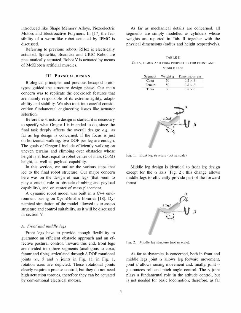
Front legs have to provide enough flexibility toguarantee an efficient obstacle approach and an ef-fective postural control. Toward this end, front legsare divided into three segments (analogous to coxa,femur and tibia), articulated through 3 DOF rotationaljoints (α, β and γ joints in Fig. 1); in Fig. 1,rotation axes are depicted. These rotational jointsclearly require a precise control, but they do not needhigh actuation torques, therefore they can be actuatedby conventional electrical motors.
As far as mechanical details are concerned, allsegments are simply modelled as cylinders whoseweights are reported in Tab. II together with thephysical dimensions (radius and height respectively).
TABLE IICOXA, FEMUR AND TIBIA PROPERTIES FOR FRONT AND
MIDDLE LEGS
Segment Weight g Dimensions cmCoxa 50 0.5 × 3
Femur 50 0.5 × 3
Tibia 30 0.5 × 6
Fig. 1. Front leg structure (not in scale).
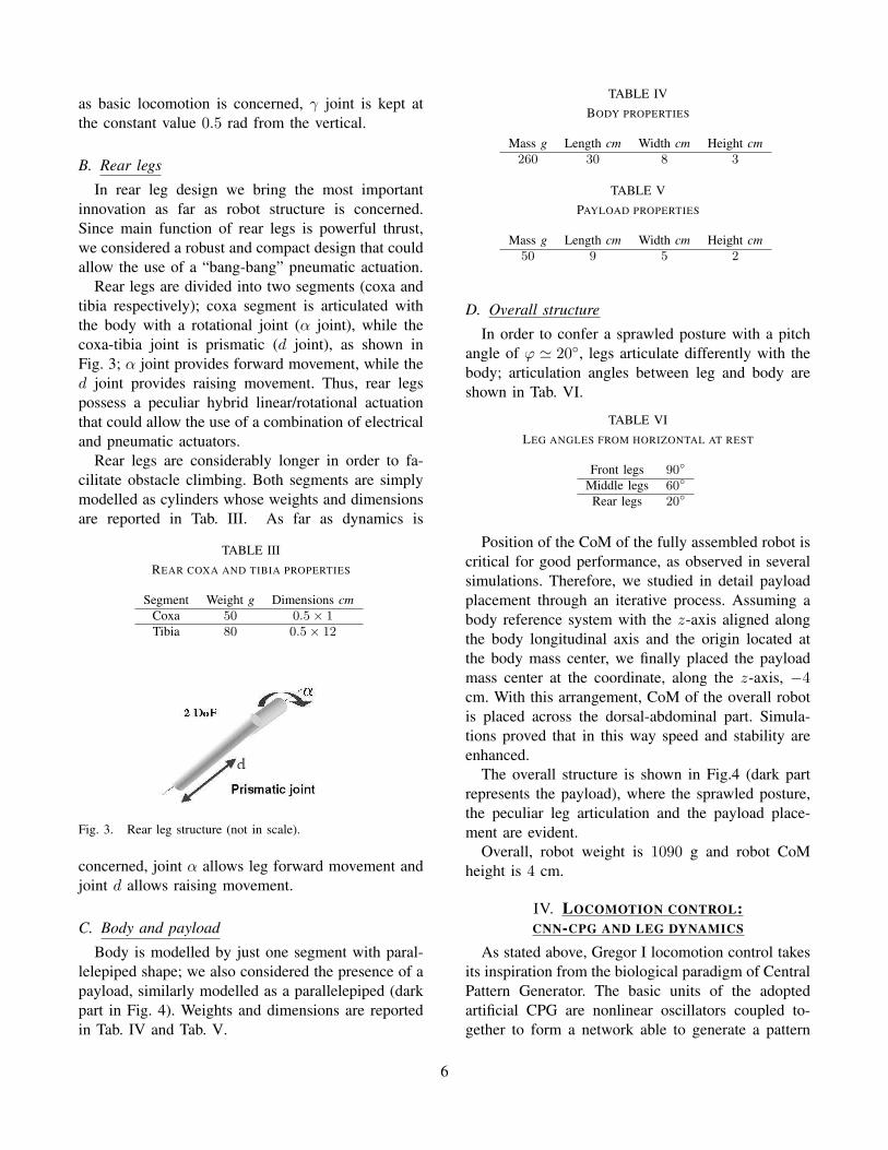
Middle leg design is identical to front leg designexcept for the α axis (Fig. 2); this change allowsmiddle legs to efficiently provide part of the forwardthrust.
Fig. 2. Middle leg structure (not in scale).
As far as dynamics is concerned, both in front andmiddle legs joint α allows leg forward movement,joint β allows raising movement and, finally, joint γguarantees roll and pitch angle control. The γ jointplays a fundamental role in the attitude control, butis not needed for basic locomotion; therefore, as far
5
as basic locomotion is concerned, γ joint is kept atthe constant value 0.5 rad from the vertical.
B. Rear legs
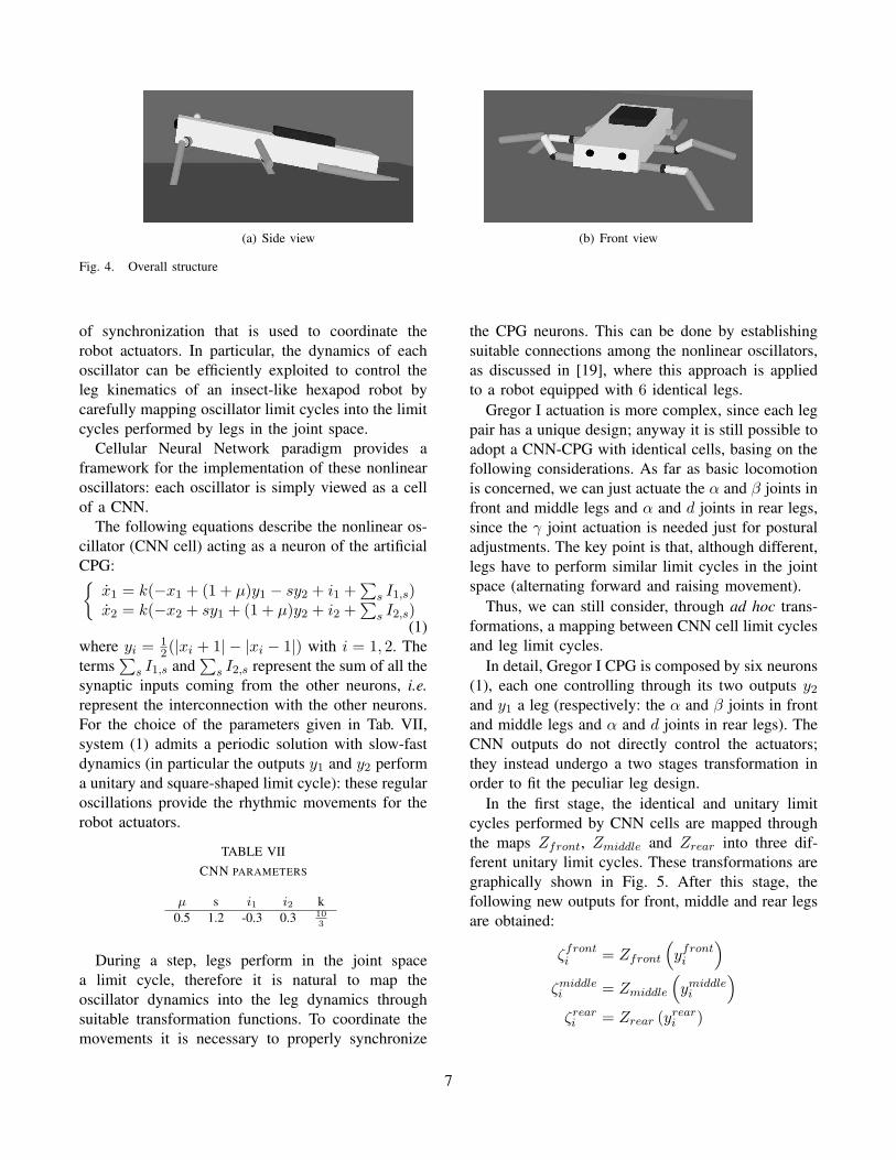
In rear leg design we bring the most importantinnovation as far as robot structure is concerned.Since main function of rear legs is powerful thrust,we considered a robust and compact design that couldallow the use of a “bang-bang” pneumatic actuation.
Rear legs are divided into two segments (coxa andtibia respectively); coxa segment is articulated withthe body with a rotational joint (α joint), while thecoxa-tibia joint is prismatic (d joint), as shown inFig. 3; α joint provides forward movement, while thed joint provides raising movement. Thus, rear legspossess a peculiar hybrid linear/rotational actuationthat could allow the use of a combination of electricaland pneumatic actuators.
Rear legs are considerably longer in order to fa-cilitate obstacle climbing. Both segments are simplymodelled as cylinders whose weights and dimensionsare reported in Tab. III. As far as dynamics is
TABLE IIIREAR COXA AND TIBIA PROPERTIES
Segment Weight g Dimensions cmCoxa 50 0.5 × 1
Tibia 80 0.5 × 12
Fig. 3. Rear leg structure (not in scale).
concerned, joint α allows leg forward movement andjoint d allows raising movement.
C. Body and payload
Body is modelled by just one segment with paral-lelepiped shape; we also considered the presence of apayload, similarly modelled as a parallelepiped (darkpart in Fig. 4). Weights and dimensions are reportedin Tab. IV and Tab. V.
TABLE IVBODY PROPERTIES
Mass g Length cm Width cm Height cm260 30 8 3
TABLE VPAYLOAD PROPERTIES
Mass g Length cm Width cm Height cm50 9 5 2
D. Overall structure
In order to confer a sprawled posture with a pitchangle of ϕ ' 20◦, legs articulate differently with thebody; articulation angles between leg and body areshown in Tab. VI.
TABLE VILEG ANGLES FROM HORIZONTAL AT REST
Front legs 90◦
Middle legs 60◦
Rear legs 20◦
Position of the CoM of the fully assembled robot iscritical for good performance, as observed in severalsimulations. Therefore, we studied in detail payloadplacement through an iterative process. Assuming abody reference system with the z-axis aligned alongthe body longitudinal axis and the origin located atthe body mass center, we finally placed the payloadmass center at the coordinate, along the z-axis, −4cm. With this arrangement, CoM of the overall robotis placed across the dorsal-abdominal part. Simula-tions proved that in this way speed and stability areenhanced.
The overall structure is shown in Fig.4 (dark partrepresents the payload), where the sprawled posture,the peculiar leg articulation and the payload place-ment are evident.
Overall, robot weight is 1090 g and robot CoMheight is 4 cm.
IV. LOCOMOTION CONTROL:CNN-CPG AND LEG DYNAMICS
As stated above, Gregor I locomotion control takesits inspiration from the biological paradigm of CentralPattern Generator. The basic units of the adoptedartificial CPG are nonlinear oscillators coupled to-gether to form a network able to generate a pattern
6
(a) Side view (b) Front view
Fig. 4. Overall structure
of synchronization that is used to coordinate therobot actuators. In particular, the dynamics of eachoscillator can be efficiently exploited to control theleg kinematics of an insect-like hexapod robot bycarefully mapping oscillator limit cycles into the limitcycles performed by legs in the joint space.
Cellular Neural Network paradigm provides aframework for the implementation of these nonlinearoscillators: each oscillator is simply viewed as a cellof a CNN.
The following equations describe the nonlinear os-cillator (CNN cell) acting as a neuron of the artificialCPG:{
x1 = k(−x1 + (1 + µ)y1 − sy2 + i1 +∑
s I1,s)x2 = k(−x2 + sy1 + (1 + µ)y2 + i2 +
∑
s I2,s)(1)
where yi = 1
2(|xi + 1| − |xi − 1|) with i = 1, 2. The
terms∑
s I1,s and∑
s I2,s represent the sum of all thesynaptic inputs coming from the other neurons, i.e.represent the interconnection with the other neurons.For the choice of the parameters given in Tab. VII,system (1) admits a periodic solution with slow-fastdynamics (in particular the outputs y1 and y2 performa unitary and square-shaped limit cycle): these regularoscillations provide the rhythmic movements for therobot actuators.
TABLE VIICNN PARAMETERS
µ s i1 i2 k0.5 1.2 -0.3 0.3 10
3
During a step, legs perform in the joint spacea limit cycle, therefore it is natural to map theoscillator dynamics into the leg dynamics throughsuitable transformation functions. To coordinate themovements it is necessary to properly synchronize
the CPG neurons. This can be done by establishingsuitable connections among the nonlinear oscillators,as discussed in [19], where this approach is appliedto a robot equipped with 6 identical legs.
Gregor I actuation is more complex, since each legpair has a unique design; anyway it is still possible toadopt a CNN-CPG with identical cells, basing on thefollowing considerations. As far as basic locomotionis concerned, we can just actuate the α and β joints infront and middle legs and α and d joints in rear legs,since the γ joint actuation is needed just for posturaladjustments. The key point is that, although different,legs have to perform similar limit cycles in the jointspace (alternating forward and raising movement).
Thus, we can still consider, through ad hoc trans-formations, a mapping between CNN cell limit cyclesand leg limit cycles.
In detail, Gregor I CPG is composed by six neurons(1), each one controlling through its two outputs y2
and y1 a leg (respectively: the α and β joints in frontand middle legs and α and d joints in rear legs). TheCNN outputs do not directly control the actuators;they instead undergo a two stages transformation inorder to fit the peculiar leg design.
In the first stage, the identical and unitary limitcycles performed by CNN cells are mapped throughthe maps Zfront, Zmiddle and Zrear into three dif-ferent unitary limit cycles. These transformations aregraphically shown in Fig. 5. After this stage, thefollowing new outputs for front, middle and rear legsare obtained:
ζfronti = Zfront
(
yfronti
)
ζmiddlei = Zmiddle
(
ymiddlei
)
ζreari = Zrear (yrear
i )
7
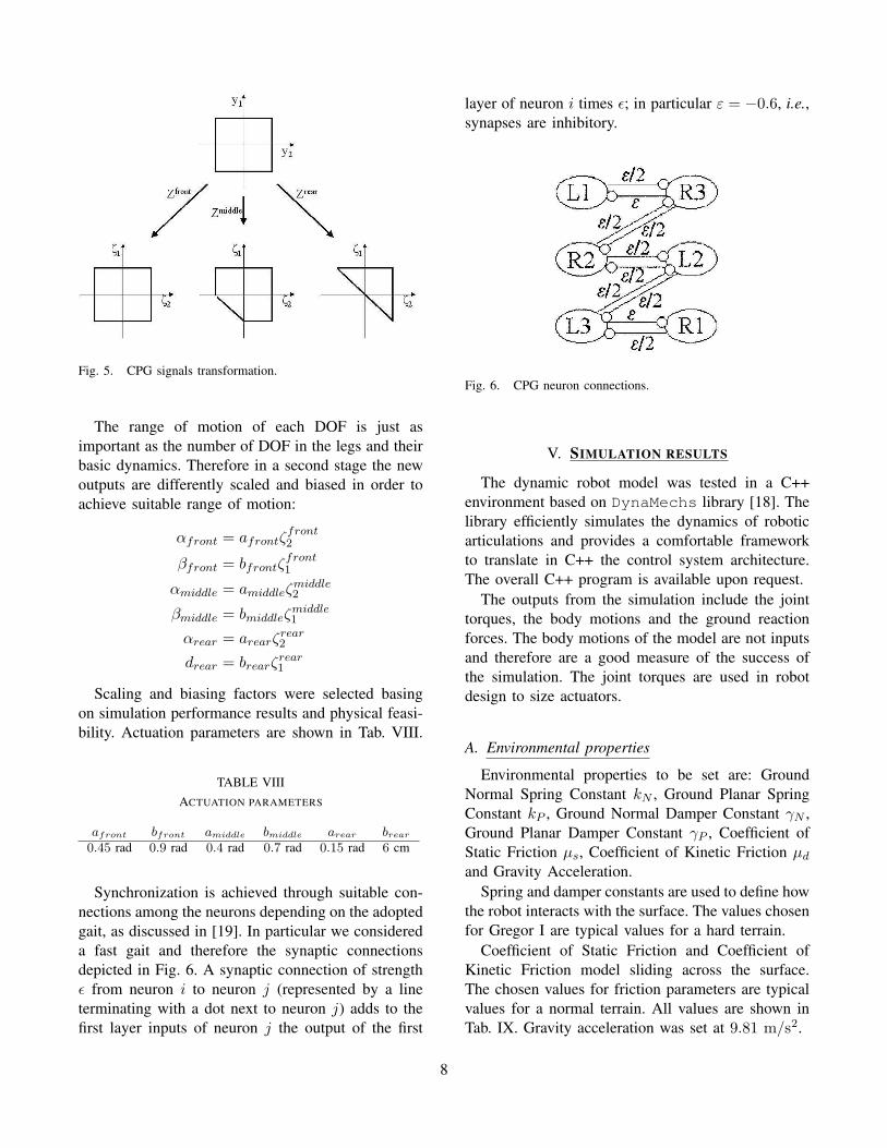
Fig. 5. CPG signals transformation.
The range of motion of each DOF is just asimportant as the number of DOF in the legs and theirbasic dynamics. Therefore in a second stage the newoutputs are differently scaled and biased in order toachieve suitable range of motion:
αfront = afrontζfront2
βfront = bfrontζfront1
αmiddle = amiddleζmiddle2
βmiddle = bmiddleζmiddle1
αrear = arearζrear2
drear = brearζrear1
Scaling and biasing factors were selected basingon simulation performance results and physical feasi-bility. Actuation parameters are shown in Tab. VIII.
TABLE VIIIACTUATION PARAMETERS
afront bfront amiddle bmiddle arear brear
0.45 rad 0.9 rad 0.4 rad 0.7 rad 0.15 rad 6 cm
Synchronization is achieved through suitable con-nections among the neurons depending on the adoptedgait, as discussed in [19]. In particular we considereda fast gait and therefore the synaptic connectionsdepicted in Fig. 6. A synaptic connection of strengthε from neuron i to neuron j (represented by a lineterminating with a dot next to neuron j) adds to thefirst layer inputs of neuron j the output of the first
layer of neuron i times ε; in particular ε = −0.6, i.e.,synapses are inhibitory.
Fig. 6. CPG neuron connections.
V. SIMULATION RESULTS
The dynamic robot model was tested in a C++environment based on DynaMechs library [18]. Thelibrary efficiently simulates the dynamics of roboticarticulations and provides a comfortable frameworkto translate in C++ the control system architecture.The overall C++ program is available upon request.
The outputs from the simulation include the jointtorques, the body motions and the ground reactionforces. The body motions of the model are not inputsand therefore are a good measure of the success ofthe simulation. The joint torques are used in robotdesign to size actuators.
A. Environmental properties
Environmental properties to be set are: GroundNormal Spring Constant kN , Ground Planar SpringConstant kP , Ground Normal Damper Constant γN ,Ground Planar Damper Constant γP , Coefficient ofStatic Friction µs, Coefficient of Kinetic Friction µd
and Gravity Acceleration.Spring and damper constants are used to define how
the robot interacts with the surface. The values chosenfor Gregor I are typical values for a hard terrain.
Coefficient of Static Friction and Coefficient ofKinetic Friction model sliding across the surface.The chosen values for friction parameters are typicalvalues for a normal terrain. All values are shown inTab. IX. Gravity acceleration was set at 9.81 m/s2.
8
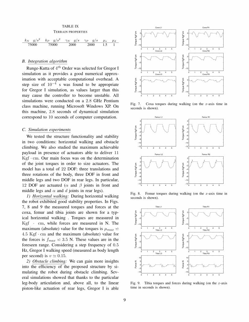
TABLE IXTERRAIN PROPERTIES
kN g/s2 kP g/s2 γN g/s γP g/s µs µd
75000 75000 2000 2000 1.5 1
B. Integration algorithm
Runge-Kutta of 4th Order was selected for Gregor Isimulation as it provides a good numerical approx-imation with acceptable computational overhead. Astep size of 10−4 s was found to be appropriatefor Gregor I simulation, as values larger than thismay cause the controller to become unstable. Allsimulations were conducted on a 2.8 GHz Pentiumclass machine, running Microsoft Windows XP. Onthis machine, 2.8 seconds of dynamical simulationcorrespond to 10 seconds of computer computation.
C. Simulation experiments
We tested the structure functionality and stabilityin two conditions: horizontal walking and obstacleclimbing. We also studied the maximum achievablepayload in presence of actuators able to deliver 11Kgf · cm. Our main focus was on the determinationof the joint torques in order to size actuators. Themodel has a total of 22 DOF: three translations andthree rotations of the body, three DOF in front andmiddle legs and two DOF in rear legs. In particular,12 DOF are actuated (α and β joints in front andmiddle legs and α and d joints in rear legs).
1) Horizontal walking: During horizontal walkingthe robot exhibited good stability properties. In Figs.7, 8 and 9 the measured torques and forces at thecoxa, femur and tibia joints are shown for a typ-ical horizontal walking . Torques are measured inKgf · cm, while forces are measured in N. Themaximum (absolute) value for the torques is µmax w
4.5 Kgf · cm and the maximum (absolute) value forthe forces is fmax w 3.5 N. These values are in theforeseen range. Considering a step frequency of 0.5Hz, Gregor I walking speed (measured as body lengthper second) is v ' 0.15.
2) Obstacle climbing: We can gain more insightsinto the efficiency of the proposed structure by si-mulating the robot during obstacle climbing. Sev-eral simulations showed that thanks to the particularleg-body articulation and, above all, to the linearpiston-like actuation of rear legs, Gregor I is able
0 1 2 3 4 5
−10
−5
0
Coxa L1
Torq
ue K
gf*c
m
0 1 2 3 4 5
−10
−5
0
Coxa R1
Torq
ue K
gf*c
m
0 1 2 3 4 5
−10
−5
0
Coxa L2
Torq
ue K
gf*c
m
0 1 2 3 4 5
−10
−5
0
Coxa R2
Torq
ue K
gf*c
m
0 1 2 3 4 5
−10
−5
0
Coxa L3
Torq
ue K
gf*c
m
0 1 2 3 4 5
−10
−5
0
Coxa R3
Torq
ue K
gf*c
m
Fig. 7. Coxa torques during walking (on the x-axis time inseconds is shown).
0 1 2 3 4 5−12
−10
−8
−6
−4
−2
0
2
Femur L1
Torq
ue K
gf*c
m
0 1 2 3 4 5−12
−10
−8
−6
−4
−2
0
2
Femur R1
Torq
ue K
gf*c
m0 1 2 3 4 5
−12
−10
−8
−6
−4
−2
0
2
Femur L2
Torq
ue K
gf*c
m
0 1 2 3 4 5−12
−10
−8
−6
−4
−2
0
2
Femur R2
Torq
ue K
gf*c
m
Fig. 8. Femur torques during walking (on the x-axis time inseconds is shown).
0 1 2 3 4 5
−10
−5
0
Tibia L1
Torq
ue K
gf*c
m
0 1 2 3 4 5
−10
−5
0
Tibia R1
Torq
ue K
gf*c
m
0 1 2 3 4 5
−10
−5
0
Tibia L2
Torq
ue K
gf*c
m
0 1 2 3 4 5
−10
−5
0
Tibia R2
Torq
ue K
gf*c
m
0 1 2 3 4 5
−10
−5
0
5
10
Tibia L3
Forc
e N
0 1 2 3 4 5
−10
−5
0
5
10
Tibia R3
Forc
e N
Fig. 9. Tibia torques and forces during walking (on the x-axistime in seconds is shown).
9
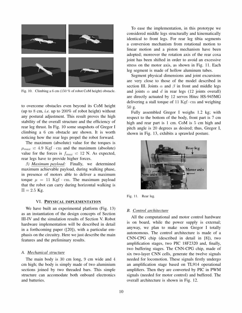
Fig. 10. Climbing a 6 cm (150 % of robot CoM height) obstacle.
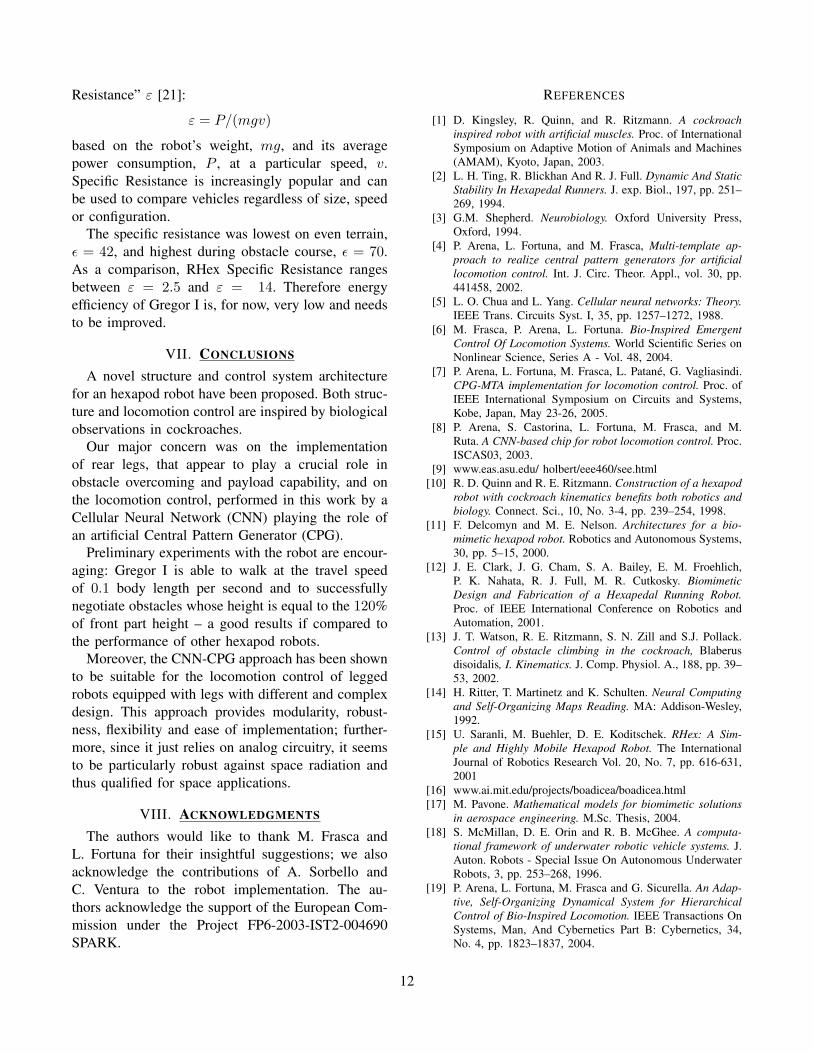
to overcome obstacles even beyond its CoM height(up to 8 cm, i.e. up to 200% of robot height) withoutany postural adjustment. This result proves the highstability of the overall structure and the efficiency ofrear leg thrust. In Fig. 10 some snapshots of Gregor Iclimbing a 6 cm obstacle are shown. It is worthnoticing how the rear legs propel the robot forward.
The maximum (absolute) value for the torques isµmax w 4.9 Kgf · cm and the maximum (absolute)value for the forces is fmax w 12 N. As expected,rear legs have to provide higher forces.
3) Maximum payload: Finally, we determinedmaximum achievable payload, during walking phase,in presence of motors able to deliver a maximumtorque µ = 11 Kgf · cm. The maximum payloadthat the robot can carry during horizontal walking isΠ = 2.5 Kg.
VI. PHYSICAL IMPLEMENTATION
We have built an experimental platform (Fig. 13)as an instantiation of the design concepts of SectionIII-IV and the simulation results of Section V. Robothardware implementation will be described in detailin a forthcoming paper ([20]), with a particular em-phasis on the circuitry. Here we just describe the mainfeatures and the preliminary results.
A. Mechanical structure
The main body is 30 cm long, 9 cm wide and 4cm high; the body is simply made of two aluminiumsections joined by two threaded bars. This simplestructure can accomodate both onboard electronicsand batteries.
To ease the implementation, in this prototype weconsidered middle legs structurally and kinematicallyidentical to front legs. For rear leg tibia segmentsa conversion mechanism from rotational motion tolinear motion and a piston mechanism have beenadopted; moreover the rotation axis of the rear coxajoint has been shifted in order to avoid an excessivestress on the motor axis, as shown in Fig. 11. Eachleg segment is made of hollow aluminum tubes.
Segment physical dimensions and joint excursionsare very close to those of the model described insection III. Joints α and β in front and middle legsand joints α and d in rear legs (12 joints overall)are directly actuated by 12 servos Hitec HS-945MGdelivering a stall torque of 11 Kgf · cm and weighing50 g.
Fully assembled Gregor I weighs 1.2 kg; withrespect to the bottom of the body, front part is 7 cmhigh and rear part is 1 cm. CoM is 5 cm high andpitch angle is 20 degrees as desired; thus, Gregor I,shown in Fig. 13, exhibits a sprawled posture.
Fig. 11. Rear leg.
B. Control architecture
All the computational and motor control hardwareis on board, while the power supply is external;anyway, we plan to make soon Gregor I totallyautonomous. The control architecture is made of aCNN-CPG chip (described in detail in [8]), twoamplification stages, two PIC 18F2320 and, finally,two buffering stages. The CNN-CPG chip, made ofsix two-layer CNN cells, generate the twelve signalsneeded for locomotion. These signals firstly undergoan amplification stage based on TL914 operationalamplifiers. Then they are converted by PIC in PWMsignals (needed for motor control) and buffered. Theoverall architecture is shown in Fig. 12.
10
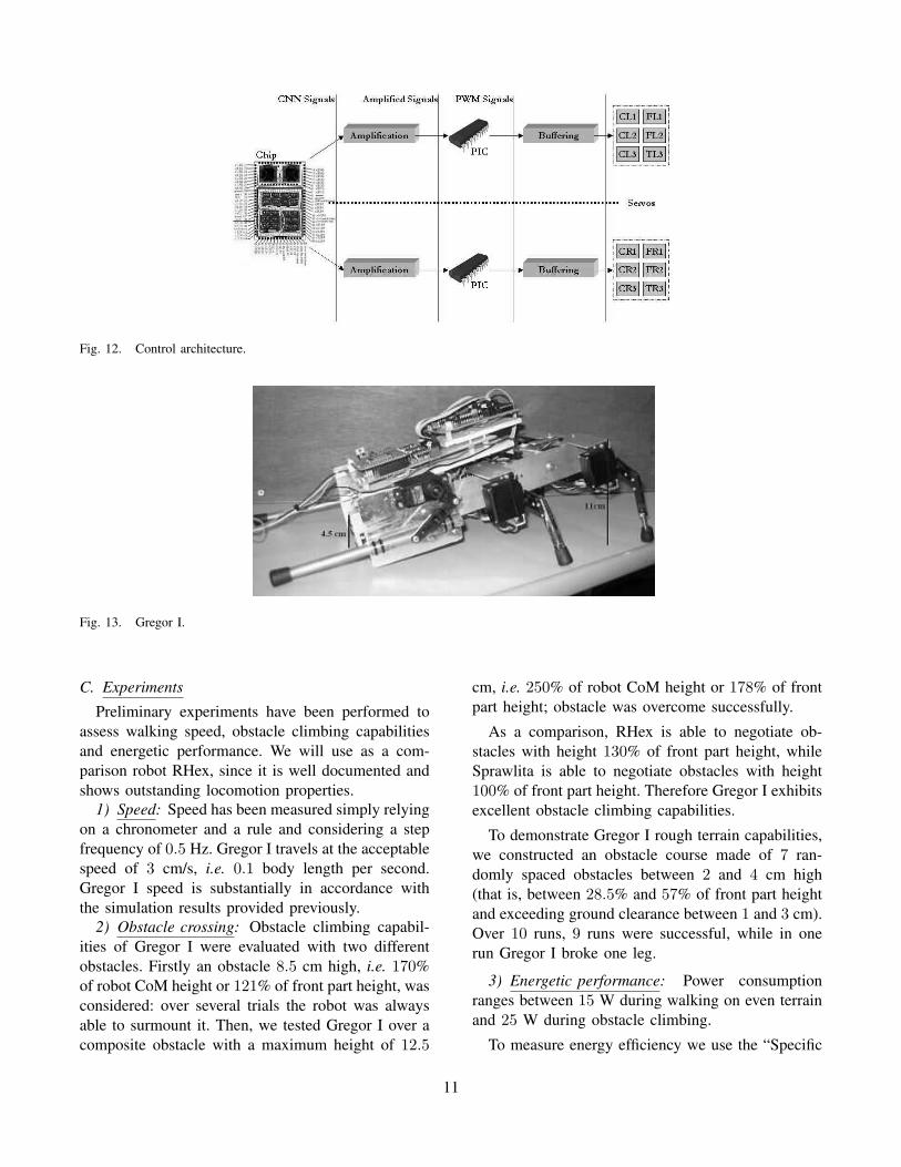
Fig. 12. Control architecture.
Fig. 13. Gregor I.
C. Experiments
Preliminary experiments have been performed toassess walking speed, obstacle climbing capabilitiesand energetic performance. We will use as a com-parison robot RHex, since it is well documented andshows outstanding locomotion properties.
1) Speed: Speed has been measured simply relyingon a chronometer and a rule and considering a stepfrequency of 0.5 Hz. Gregor I travels at the acceptablespeed of 3 cm/s, i.e. 0.1 body length per second.Gregor I speed is substantially in accordance withthe simulation results provided previously.
2) Obstacle crossing: Obstacle climbing capabil-ities of Gregor I were evaluated with two differentobstacles. Firstly an obstacle 8.5 cm high, i.e. 170%of robot CoM height or 121% of front part height, wasconsidered: over several trials the robot was alwaysable to surmount it. Then, we tested Gregor I over acomposite obstacle with a maximum height of 12.5
cm, i.e. 250% of robot CoM height or 178% of frontpart height; obstacle was overcome successfully.
As a comparison, RHex is able to negotiate ob-stacles with height 130% of front part height, whileSprawlita is able to negotiate obstacles with height100% of front part height. Therefore Gregor I exhibitsexcellent obstacle climbing capabilities.
To demonstrate Gregor I rough terrain capabilities,we constructed an obstacle course made of 7 ran-domly spaced obstacles between 2 and 4 cm high(that is, between 28.5% and 57% of front part heightand exceeding ground clearance between 1 and 3 cm).Over 10 runs, 9 runs were successful, while in onerun Gregor I broke one leg.
3) Energetic performance: Power consumptionranges between 15 W during walking on even terrainand 25 W during obstacle climbing.
To measure energy efficiency we use the “Specific
11
Resistance” ε [21]:
ε = P/(mgv)
based on the robot’s weight, mg, and its averagepower consumption, P , at a particular speed, v.Specific Resistance is increasingly popular and canbe used to compare vehicles regardless of size, speedor configuration.
The specific resistance was lowest on even terrain,ε = 42, and highest during obstacle course, ε = 70.As a comparison, RHex Specific Resistance rangesbetween ε = 2.5 and ε = 14. Therefore energyefficiency of Gregor I is, for now, very low and needsto be improved.
VII. CONCLUSIONS
A novel structure and control system architecturefor an hexapod robot have been proposed. Both struc-ture and locomotion control are inspired by biologicalobservations in cockroaches.
Our major concern was on the implementationof rear legs, that appear to play a crucial role inobstacle overcoming and payload capability, and onthe locomotion control, performed in this work by aCellular Neural Network (CNN) playing the role ofan artificial Central Pattern Generator (CPG).
Preliminary experiments with the robot are encour-aging: Gregor I is able to walk at the travel speedof 0.1 body length per second and to successfullynegotiate obstacles whose height is equal to the 120%of front part height – a good results if compared tothe performance of other hexapod robots.
Moreover, the CNN-CPG approach has been shownto be suitable for the locomotion control of leggedrobots equipped with legs with different and complexdesign. This approach provides modularity, robust-ness, flexibility and ease of implementation; further-more, since it just relies on analog circuitry, it seemsto be particularly robust against space radiation andthus qualified for space applications.
VIII. ACKNOWLEDGMENTS
The authors would like to thank M. Frasca andL. Fortuna for their insightful suggestions; we alsoacknowledge the contributions of A. Sorbello andC. Ventura to the robot implementation. The au-thors acknowledge the support of the European Com-mission under the Project FP6-2003-IST2-004690SPARK.
REFERENCES
[1] D. Kingsley, R. Quinn, and R. Ritzmann. A cockroachinspired robot with artificial muscles. Proc. of InternationalSymposium on Adaptive Motion of Animals and Machines(AMAM), Kyoto, Japan, 2003.
[2] L. H. Ting, R. Blickhan And R. J. Full. Dynamic And StaticStability In Hexapedal Runners. J. exp. Biol., 197, pp. 251–269, 1994.
[3] G.M. Shepherd. Neurobiology. Oxford University Press,Oxford, 1994.
[4] P. Arena, L. Fortuna, and M. Frasca, Multi-template ap-proach to realize central pattern generators for artificiallocomotion control. Int. J. Circ. Theor. Appl., vol. 30, pp.441458, 2002.
[5] L. O. Chua and L. Yang. Cellular neural networks: Theory.IEEE Trans. Circuits Syst. I, 35, pp. 1257–1272, 1988.
[6] M. Frasca, P. Arena, L. Fortuna. Bio-Inspired EmergentControl Of Locomotion Systems. World Scientific Series onNonlinear Science, Series A - Vol. 48, 2004.
[7] P. Arena, L. Fortuna, M. Frasca, L. Patane, G. Vagliasindi.CPG-MTA implementation for locomotion control. Proc. ofIEEE International Symposium on Circuits and Systems,Kobe, Japan, May 23-26, 2005.
[8] P. Arena, S. Castorina, L. Fortuna, M. Frasca, and M.Ruta. A CNN-based chip for robot locomotion control. Proc.ISCAS03, 2003.
[9] www.eas.asu.edu/ holbert/eee460/see.html[10] R. D. Quinn and R. E. Ritzmann. Construction of a hexapod
robot with cockroach kinematics benefits both robotics andbiology. Connect. Sci., 10, No. 3-4, pp. 239–254, 1998.
[11] F. Delcomyn and M. E. Nelson. Architectures for a bio-mimetic hexapod robot. Robotics and Autonomous Systems,30, pp. 5–15, 2000.
[12] J. E. Clark, J. G. Cham, S. A. Bailey, E. M. Froehlich,P. K. Nahata, R. J. Full, M. R. Cutkosky. BiomimeticDesign and Fabrication of a Hexapedal Running Robot.Proc. of IEEE International Conference on Robotics andAutomation, 2001.
[13] J. T. Watson, R. E. Ritzmann, S. N. Zill and S.J. Pollack.Control of obstacle climbing in the cockroach, Blaberusdisoidalis, I. Kinematics. J. Comp. Physiol. A., 188, pp. 39–53, 2002.
[14] H. Ritter, T. Martinetz and K. Schulten. Neural Computingand Self-Organizing Maps Reading. MA: Addison-Wesley,1992.
[15] U. Saranli, M. Buehler, D. E. Koditschek. RHex: A Sim-ple and Highly Mobile Hexapod Robot. The InternationalJournal of Robotics Research Vol. 20, No. 7, pp. 616-631,2001
[16] www.ai.mit.edu/projects/boadicea/boadicea.html[17] M. Pavone. Mathematical models for biomimetic solutions
in aerospace engineering. M.Sc. Thesis, 2004.[18] S. McMillan, D. E. Orin and R. B. McGhee. A computa-
tional framework of underwater robotic vehicle systems. J.Auton. Robots - Special Issue On Autonomous UnderwaterRobots, 3, pp. 253–268, 1996.
[19] P. Arena, L. Fortuna, M. Frasca and G. Sicurella. An Adap-tive, Self-Organizing Dynamical System for HierarchicalControl of Bio-Inspired Locomotion. IEEE Transactions OnSystems, Man, And Cybernetics Part B: Cybernetics, 34,No. 4, pp. 1823–1837, 2004.
12
[20] P. Arena, L. Fortuna, M. Frasca, L. Patan, M. Pavone. Im-plementation and experimental validation of an autonomoushexapod robot. To appear in Proc. of IEEE InternationalSymposium on Circuits and Systems, Kos, Greece, May 21-24, 2006.
[21] G. Gabrielli and T. H. von Karman. What price speed?.Mechanical Engineering, vol. 72, no. 10, pp. 775781, 1950.
13