an inductance-based sensing system for bellows-driven ... · an inductance-based sensing system for...
TRANSCRIPT

An Inductance-Based Sensing Systemfor Bellows-Driven Continuum Joints in Soft Robots
Wyatt Felt∗, Maria J. Telleria†, Thomas F. Allen†, Gabriel Hein†, Jonathan B. Pompa†, Kevin Albert†, C. David Remy∗∗ Robotics and Motion Laboratory (RAMlab), University of Michigan, Ann Arbor, MI. Emails: (wfelt, cdremy)@umich.edu
† Pneubotics, an Otherlab Company, San Fransisco, CA. Email: [email protected]
Abstract—In this work we present a novel, inductance-basedsystem to measure and control the motion of bellows-drivencontinuum joints in soft robots. The sensing system relies oncoils of wire wrapped around the minor diameters of each bellowson the joint. As the bellows extend, these coils of wire becomemore distant, decreasing their mutual inductance. Measuring thischange in mutual inductance allows us to measure the motion ofthe joint. By dividing the sensing of the joint into two sections andmeasuring the motion of each section independently, we are ableto measure the overall deformation of the joint with a piece-wise constant-curvature approximation. This technique allowsus to measure lateral displacements that would be otherwiseunobservable. When measuring bending, the inductance sensorsmeasured the joint orientation with an RMS error of 1.1 ◦. Theinductance sensors were also successfully used as feedback tocontrol the orientation of the joint. The sensors proposed andtested in this work provided accurate motion feedback that wouldbe difficult to achieve robustly with other sensors. This sensingsystem enables the creation of robust, self-sensing, and soft robotsbased on bellows-driven continuum joints.
I. INTRODUCTION
The emerging field of soft robotics is enabling fundamen-tally new ways to design, build, and control robotic systems.Such soft robots exhibit complex behaviors that emerge fromdeliberate compliance in the actuators and structure. By in-corporating passive degrees of freedom into their structure,soft robots can passively conform to the constraints of theirenvironment and to the objects they are manipulating. Manysoft robots are actuated by the flexible expansion of hermeti-cally sealed volumes driving compliant joints. Systems basedon these principles are lightweight, flexible and have lowreflected inertia. This makes them inherently safe in physicalhuman robot interaction. Moreover, the sealed actuators andflexible joints are well-suited to work in harsh environmentswhere external contaminates could breach the dynamic sealsof rotating or sliding shafts.
In this paper, we focus on sensing and controlling the mo-tion of bellows-driven continuum joints. The sensing systemrelies on coils of insulated conductive wire wrapped around theminor diameters of the bellows. These coils form circuits withinductance values that change with the length of the bellows.The measured inductance values can be calibrated to measurethe motion of the joint. We demonstrate experimentally howsensors such as these can measure and control the motion ofbellows-driven continuum joints.
We utilize a joint made from four pneumatically driven
Fig. 1. Bellows-driven continuum joints are used to create robots withoutfinite degrees of freedom. Sensing the motion of such robots is a challenge.The inductance-based sensors presented in this work will bring estimation andcontrol to robots like the one pictured here (created by Pneubotics).
bellows that are positioned around a central steel cable (Fig. 1).This joint has been developed by Pneubotics. The bellowscreate bending torques about two axes while keeping the jointstiff in torsion. By pressurizing pairs of antagonized bellowssimultaneously, the passive bending stiffness of the joint is alsocontrollable. Joints with similar features have been developedfor applications in industry and academia. These have reliedon bellows [10, 3, 15, 12, 11] and other soft, fluid-poweredactuators [5, 18, 16].
The advantages of soft continuum joints come with thenew challenge of sensing and controlling their distributedmotion. While traditional robotic systems provide discretemechanical joints on which to couple rotational or translationalsensors, soft continuum joints, by their nature, do not havesuch convenient coupling points. Instead, the deformation ofsoft joints is typically measured with an external localizationsystem, inertial measurement units (IMUs), or a set of internalsensors.
External localization systems include visual “3D motioncapture,” electromagnetic tracking, and radio frequency indoorpositioning systems. Visual localization systems typically relyon retro-reflective markers or laser beacons [31, 22]. Thesesystems require a line-of-sight to operate. Accordingly, theyhave limited utility in visually occluded workspaces. Electro-magnetic tracking systems [29, 23] avoid these occlusion prob-lems but have smaller workspaces. Radio Frequency systemsmay have vast workspaces but limited accuracy [30]. More-over, high-frequency signals rapidly attenuate underwater.
In some situations, IMUs can be used to estimate the motion

of difficult-to-sense joints in robots and humans [13, 4].Orientation estimates from IMUs, however, are not alwaysaccurate. Without reliable magnetic field information, IMUheading estimates are susceptible to drift. Naturally, orienta-tion estimates can only measure robot motion that changesorientation. This is not always the case. Continuum joints, forexample, can deflect laterally without changing the relativeorientation of the joint ends.
Internal sensors measure the deformation in the systemdirectly. The deformation can be measured, for example, byrecording changes in length along well-defined paths. Thelength of joint sections, for example, can be measured throughthe recoil of strings or tendons under tension [16, 10]. Straincan also be measured using elastomers with elements thatexhibit changes in resistance or capacitance [2, 24, 26].Optical fibers can measure strain (and thus bending) via FiberBragg Gratings [17] or deformation-induced attenuation [25].Elastomeric waveguides can also be used [32, 28]. The shapeof cable-like sensors can be measured through the changingdistance between pairs of LEDs and phototransistors [14, 11].Inductance-based sensors have been developed by the authorsFelt and Remy for use in soft actuators such as bendingbellows [8] and McKibben muscles [7, 9, 6].
Among these sensing technologies, inductance-based sen-sors provide unique advantages. String recoil systems areoften bulky and fragile. Elastomeric and optical fiber systemscan fail under repeated strain and may require specializedequipment to fabricate. Inductance-based systems rely on off-the-shelf, high-flex-life wire to create inexpensive and low-profile sensors.
The primary contribution of this work is the introductionof inductance sensors that measure the motion of bellows-driven continuum joints. We develop the theory, models anddesign principles for these sensors. The experimental sensingsystem measures the motion of the joint independently in twohalves along the joint length. This allows us to measure lateraldisplacement even when there is no change in orientationbetween the ends. The performance of the sensing system istested in both quasi-static conditions and as feedback for thecontrol of a bellows-driven joint.
The hardware of our experimental system is described inSection II. Section III discusses theory, including the kinemat-ics of the joint (III-A), models for the inductance sensor (III-B)and design principles relating to the same (III-C). SectionIII-D investigates the use of “split-joint” sensing to measurelateral displacement. Our experimental methods and resultsare described in Section IV. This includes the calibration andverification of the sensing system (IV-A), the estimation ofthe joint position under lateral loads (IV-B) and the feedbackcontrol of the joint orientation (IV-C). This is followed by ageneral discussion in Section V.
II. HARDWARE
Our inductance-based sensing system was implemented on acommercial, bellows-driven continuum joint. To create a self-sensing joint based on inductance, the minor diameters of the
bellows were wrapped with flexible wire (Fig. 2). This createdcircuits of circular coils spaced along the length of the bellows.As a bellows expanded in length, the circular coils movedfarther apart, reducing the inductance of the correspondingcircuit. The joint was instrumented and controlled to calibrateand test the inductance-based sensing system.
Fig. 2. The minor diameters of the plastic bellows were wrapped withinsulated conductive wire (red and blue). The inductance of the circuitprovides a measure of the bellows length.
The joint was provided by Pneubotics (an Otherlab com-pany, San Fransico, CA, USA, Fig. 1). The joint consists oftwo plates connected to four bellows spaced around a centralsteel cable. The centers of the bellows are kept at a fixeddistance, designated b, of 4.9 cm from the central cable. Thesteel cable has a length h of 19.7 cm between the plates of thejoint. It provides a “fulcrum” to convert the extension forcesof the bellows into bending moments. The bellows have 26major diameters between the plates of the joint. The majorand minor diameters of the bellows are 6.7 cm and 4.9 cm,respectively. The joint is actuated by pressurizing the bellowswith compressed air. The antagonized configuration of the fourbellows creates a 2-DOF bending joint with independentlycontrollable joint torque and passive stiffness. The unmodifiedjoint has a range of motion of ±90 ◦ in each axis. In this work,the pressure in the bellows was maintained below 0.41 MPa.
The joint was outfitted with four distinct inductance circuits(Fig. 3). Pairs of adjacent circuits measured the bending ineach half of the joint. The circuits were formed from “tinsel”wire with a high flex-fatigue life (TN3637, 1.14 mm outerdiameter, resistance 538 ohms/km, MN wire, St. Paul, MN, USA).The flexible wire was wrapped around 12 minor diameters ofthe bellows in the corresponding half. Each minor diameterhad two turns of current (except at the ends of the circuitswhere there was only one turn). The inductance was measuredwith an LDC1614 chip (Excitation voltage: 1.2-1.8 V, TexasInstruments, Dallas, TX, USA). This chip measures the res-onant frequency of four inductor-capacitor oscillating circuitsin rapid succession. To this end, each inductive circuit wasconnected in parallel with a high-precision (1 %, NP0) 100 pFceramic capacitor.
To provide a ground truth reference for our sensor, the jointwas mounted upside-down on a level mount such that therelative orientation of the ends could be measured with an IMU(Dynamic accuracy: ±1 ◦, 3-Space Micro USB, magnetometerdisabled, Yost Labs, Portsmouth, OH, USA). A 38 cm arm wasattached to the end of the joint for calibration and testing.

Fig. 3. The deformation of the entire joint was approximated as thecomposition of two constant-curvature sections. Pairs of adjacent inductivesensor circuits (orange and blue circles) measured the bending of the eachhalf independently. This “split-joint” configuration allows us to estimate thejoint motion in non-uniform-curvature conditions.
Weights were added to the end of the arm to create differentloading conditions. The pressure in the bellows was controlledwith electronic pressure regulators (TR, Enfield Technologies,Shelton, CT, USA). The data acquisition and control wasfacilitated by LabVIEW.
III. THEORY
A. Kinematic Model
The joint was modeled as the composition of two constantcurvature sections (Fig. 3). This was designed to allow thedeformation to be approximated even when the curvatureacross the length of the joint is not uniform.
For each constant-curvature section of the joint, the coordi-nate axes in the base frame originate at the center of the centralcable and intersect with the bellows’ centers (Fig. 4). The x-axis points towards bellows 1, the y-axis towards bellows 2,and the z-axis along the central cable (when straight). Thebellows’ centers are separated from the central cable by theconstant distance b.
We describe the kinematics of each constant curvaturesection joint using a parametrization presented by Allen, etal. [1]. This parametrization has several desirable properties.It remains invertible in the straight configuration and has affinerelationships between the rotation parameters and the lengthsof the bellows. This parametrization is based on the twocomponents, u and v, of a rotation vector ω = [u, v, 0]
T . Thez-component is always zero. This rotation vector ω describesthe orientation of the top of the plate relative to the base and isequivalent to rotating the top plate by an angle θ =
√u2 + v2
around the unit vector ω/‖ω‖. The rotation vector ω can alsobe described by the angles φ and θ
ω = [u, v, 0]T
= [−θ sinφ, θ cosφ, 0]T. (1)
The homogeneous transformation from the base frameto a frame with distance h along the cable (assumingconstant curvature across that distance) is given by the matrix
b)
x
y
ϕ
b θ
b
12
3
4
l 3
l 1
h/2
a)
Fig. 4. (a) Photo of a 2-DOF bellows-driven continuum joint. The orangefibers constrain the bellows around the central cable. (b) The kinematic modelof the joint. Each half of the joint undergoes a bend angle θ with an orientationφ. The center of the joint is reinforced by a cable of length h (thick blackline). The bellows are indexed from one to four. The center-lines of the halfbellows (thin blue and orange lines) have lengths of l1, l2, l3 and l4. Thecenters of the bellows are spaced from the central cable by a distance b.
g (u, v, h)
g (u, v, h) =
γv2 + 1 −γuv ζv −γhv−γuv γu2 + 1 −ζu γhu−ζv ζu cos (θ) ζh
0 0 0 1
. (2)
The functions ζ (θ) = sin (θ) /θ and γ (θ) = (cos (θ)− 1) /θ2
are defined when θ is zero. This is apparent from the Maclaurinseries of sine and cosine.
The lengths l = f (u, v) of the half-bellows sections alongtheir center-lines are expressed as follows:
[l1, l2, l3, l4]T
=h
2+ b [−v, u, v, −u]
T. (3)
Because h is fixed, the length l of each bellows section is afunction of either only v or only u.
The bending in the distal half of the joint was defined byωa = [ua, va, 0]
T and measured by the inductance values onthe distal halves of bellows 1 and 2 (Fig. 3, blue). The proximaljoint half was defined by ωb = [ub, vb, 0]
T and measured withinductance sensors on bellows 3 and 4 (Fig. 3, orange).
B. Inductance Model
The inductive circuits are modeled as n circular coils ofcurrent connected electrically in series. Each circular coilis made up of N turns of wire. The total inductance L ofthe circuit is the sum of the self-inductance L′i,i and mutualinductance Mi,j of the coils in the circuit. The total inductanceL =
∑ni=1
∑nj=1 L [i, j] is the sum of the elements in the
inductance matrix L
L =
L′1,1 M1,2 M1,3 . . . M1,n
M2,1 L′2,2 M2,3 . . . M2,n
M3,1 M3,2 L′3,3 . . . M3,n
......
.... . .
...Mn,1 Mn,2 Mn,3 . . . L′n,n
. (4)
The self-inductance of the individual coils L′i,i does notchange during actuation. A circular wire coil with N turnsof current, a coil radius r and a wire radius a has a self-inductance that is approximated by
L′i,i ≈ µN2r
(ln
(8r
a
)− 2
). (5)
This approximation assumes that the current distribution isconcentrated on the surface of the conductors. µ is the mag-netic permeability of the surrounding medium (approximately4π × 10−7 H/m for nonmagnetic materials such as plastic andair).
The sensitivity of the inductance to joint motion comes fromthe change in mutual inductance between coils on different mi-nor diameters. For these current paths, the mutual inductanceis calculated numerically by integrating the Neumann formula[19]. For two paths in 3D space
C1 (s1) = [x1 (s1) , y1 (s1) , z1 (s1)]T
C2 (s2) = [x2 (s2) , y2 (s2) , z2 (s2)]T
(6)
parameterized by s1 = [0, 1], s2 = [0, 1], the mutual induc-tance is given the double integral
M1,2 =µ
4π
∫ 1
0
∫ 1
0
(dC1
ds1|s1)(
dC2
ds2|s2)T
√(C1 −C2) (C1 −C2)
Tds1ds2. (7)
The mutual inductance between two N -turn coils on sepa-rate convolutions was approximated as N2 times the mutualinductance between single-turn coils (circular loops) on theminor diameters of the bellows. This approximation is accuratewhen the distance between the turns in each coil is smallrelative to the distance between the two coils.
The inductance values of the circuits on the bellows changewith the deformation of their corresponding joint section. Forexample, the inductance of a sensor on bellows 1 in theproximal half of the joint, L1a = f (ua, va), is a functionof the curvature of the joint in that half. In order to measurethe motion of the joint, we desire to invert this relationship(e.g. ua = f (L1a, L2a, L3a, L4a)). We used the kinematicand inductance models to investigate which combinations ofinductance sensors are suitable for use in this inversion. Tothis end, Eq. (7) was used to calculate the inductance of thecircuits at different joint orientations. A circular loop of currentwas first defined as a geometric path. This path was thentransformed by Eq. (2) to the appropriate positions around thejoint as it underwent constant-curvature bending. For each pairof circular loops in a circuit, Eq. (7) was integrated with theMATLAB integral2 function. To examine the effect of sensorplacement, the sensors were modeled to be on the same sectionof the joint (i.e. with geometries dependent on ua and va). Inthis configuration, the length change of the sensor modeled onbellows 1 was equal and opposite of that on bellows 3. Thesame relationship holds for bellows 2 and 4.
The geometry and corresponding inductance values werecalculated at each combination of a series of 22 values of
φ and 12 values of θ. The values of φ were equally spacedbetween 0 ◦ and 343.64 ◦ and the values of θ where equallyspaced between 0 ◦ and 90 ◦. The inductance values werecalculated only once when θ = 0 (where φ does not changethe geometry).
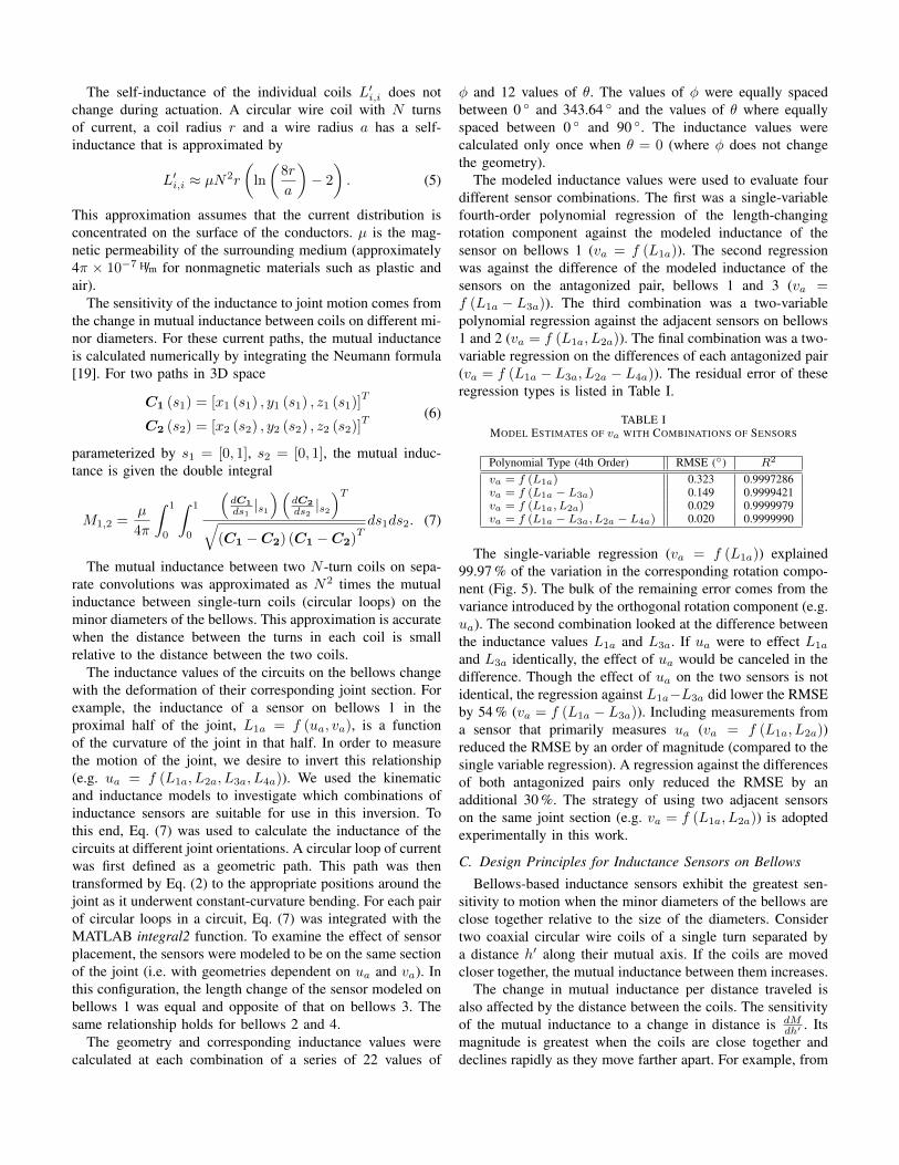
The modeled inductance values were used to evaluate fourdifferent sensor combinations. The first was a single-variablefourth-order polynomial regression of the length-changingrotation component against the modeled inductance of thesensor on bellows 1 (va = f (L1a)). The second regressionwas against the difference of the modeled inductance of thesensors on the antagonized pair, bellows 1 and 3 (va =f (L1a − L3a)). The third combination was a two-variablepolynomial regression against the adjacent sensors on bellows1 and 2 (va = f (L1a, L2a)). The final combination was a two-variable regression on the differences of each antagonized pair(va = f (L1a − L3a, L2a − L4a)). The residual error of theseregression types is listed in Table I.
TABLE IMODEL ESTIMATES OF va WITH COMBINATIONS OF SENSORS
Polynomial Type (4th Order) RMSE (◦) R2
va = f (L1a) 0.323 0.9997286va = f (L1a − L3a) 0.149 0.9999421va = f (L1a, L2a) 0.029 0.9999979va = f (L1a − L3a, L2a − L4a) 0.020 0.9999990
The single-variable regression (va = f (L1a)) explained99.97 % of the variation in the corresponding rotation compo-nent (Fig. 5). The bulk of the remaining error comes from thevariance introduced by the orthogonal rotation component (e.g.ua). The second combination looked at the difference betweenthe inductance values L1a and L3a. If ua were to effect L1a
and L3a identically, the effect of ua would be canceled in thedifference. Though the effect of ua on the two sensors is notidentical, the regression against L1a−L3a did lower the RMSEby 54 % (va = f (L1a − L3a)). Including measurements froma sensor that primarily measures ua (va = f (L1a, L2a))reduced the RMSE by an order of magnitude (compared to thesingle variable regression). A regression against the differencesof both antagonized pairs only reduced the RMSE by anadditional 30 %. The strategy of using two adjacent sensorson the same joint section (e.g. va = f (L1a, L2a)) is adoptedexperimentally in this work.
C. Design Principles for Inductance Sensors on Bellows
Bellows-based inductance sensors exhibit the greatest sen-sitivity to motion when the minor diameters of the bellows areclose together relative to the size of the diameters. Considertwo coaxial circular wire coils of a single turn separated bya distance h′ along their mutual axis. If the coils are movedcloser together, the mutual inductance between them increases.
The change in mutual inductance per distance traveled isalso affected by the distance between the coils. The sensitivityof the mutual inductance to a change in distance is dM
dh′ . Itsmagnitude is greatest when the coils are close together anddeclines rapidly as they move farther apart. For example, from

Fig. 5. The results of the inductance model for the joint used in this work.Much of the variation in the rotational components (e.g. va) is explainedby a simple polynomial regression against the inductance of a coil on thelength-changing bellows (e.g. L1a).
Fig. 6. Shown is the mutual inductance sensitivity to separation of twocoaxial circles of equal diameter (1 m) separated by a distance h′. The changein mutual inductance per distance traveled declines rapidly as the coils movefarther apart.
an axial distance of h′ = .05 diameters to h′ = 1 diameter,the sensitivity decreases by approximately two orders ofmagnitude (Fig. 6).
Thus inductance sensors are best-suited to work on bellowswith minor diameters that are spaced much more closelythan the size of the diameters themselves. The bellows usedin this work, for example, have h′ values of approximately0.014 diameters when the joint is straight.
Another consideration is how many turns of wire to use ineach coil. This consideration has trade-offs in sensor qualityand actuation range. One measure of the quality of an induc-tance sensor is the “Quality Factor” Q
Q = 2πfexciteL
R(8)
where R is the resistance, L the inductance, and fexcite theexcitation frequency. The maximum excitation frequency isoften limited by the sensing circuitry or parasitic capacitance[21]. Thus, for a given frequency, it is desirable to maximizethe ratio of inductance to resistance. The inductance scaleswith the radius r of the coils and with the square of the numberof turns N2 in each coil
L ∝ rN2. (9)
The resistance is proportional to the number of turns N andthe radius r of the circular coils and inversely proportional tothe cross-sectional area of the conductor Awire
R ∝ Nr
Awire. (10)
Fig. 7. The geometry of the joint was simulated with a level displacementd. Our models predict that using two circuits along the length of the jointimproves the estimation of deformations like these.
Accordingly, the inductance to resistance ratio scales linearlywith the number of turns N and the cross-sectional area ofthe conductors Awire
L
R∝ NAwire. (11)
Thus, increasing the number of turns in each coil or in-creasing the cross-sectional area of the conductors increasesthe sensor quality. However, there are trade-offs to increasingthese quantities. Increasing the number of turns can increasethe parasitic capacitance which, if it becomes too high, canlower the feasible excitation frequency [21]. Furthermore, thewires take up physical space on the minor diameters. Thecross-sectional area Acoil of the circular coils scales in thesame way as L
R
Acoil ∝ NAwire. (12)
This bulk of material in the convolutions could limit con-traction of the bellows. This also suggests that, for a fixedexcitation frequency, a high quality factor is more easilyachieved with a physically larger system. In this work, thenumber of turns of wire in each of the circular coils was keptat a minimum.
D. Measuring Non-uniform Curvature
When actuated against external loads, the joint may besubject to non-uniform internal bending moments. These maylead to non-uniform curvature along the length of the joint.Measuring the curvature of the joint in multiple sections canimprove the ability of the joint to sense certain non-uniform-curvature deformations. To demonstrate how multiple sensingsections can improve the estimation of the joint motion, wesimulated the lateral displacement of the joint end with nochange in orientation of the plates (Fig. 7). The chosendisplacement was selected to highlight the opportunity of usingmultiple sensors along the joint length.
For this simulation, the profile of the central cable wasapproximated with the simple planar equations of a thincantilever. The cantilever we considered has a fixed end andis free but guided at the other end. A force and moment atthe free end deflect it a distance d without rotation at the tip.

The profile of the cantilever with this deflection is given bythe following expression [20]
x (z) =dz2
l3(3l − 2z) (13)
where z is measured from the support along the length of theunloaded beam. l is the distance in z between the ends. l isselected to conserve the length of the central cable.
The geometry of the central cable and coils was calculatedfor a a lateral displacement of d = 2 cm in the xz-plane alongthe x-axis towards bellows 1. The profile of the central cablewas defined by Eq. (13). The geometric paths describing thecircular loops of current were transformed via Eq. (13) to theirpositions in the displaced configuration (Fig. 7). The mutualinductance between the loops on bellows 1 was then calculatedwith Eq. (7) and the MATLAB integral2 function. Three differ-ent circuit configurations were modeled: one circuit spanningthe entire bellows length (25 coils), two circuits (12 coilsin each half), and three circuits (8-9-8, in each approximatethird). The bending in each section was estimated by usingthe inductance values predicted for the lateral displacement inequations calibrated to constant-curvature bending. A single-variable, 4th-order polynomial (e.g. va = f (L1a)) was usedfor each circuit. The deformation of the total joint wasthen estimated by composing the curvatures predicted by thecalibration equations in each section.
For this type of lateral displacement, using two circuits perlength of the joint (compared to one) was predicted to lead tosmaller error in the estimates of d, l and θ (Table II). Threecircuits was predicted to further reduce the errors in d and l.
TABLE IIMODEL-PREDICTED ERROR IN INDUCTANCE-BASED ESTIMATES FOR A
LATERAL DISPLACEMENT OF 2 CM
Number of CircuitsVariable 1 2 3d (mm) -21.01 -4.88 -2.16l (mm) 1.22 0.46 0.22θ (◦) 0.59 -0.31 -0.42
IV. EXPERIMENTAL EVALUATION
A. Calibration and Verification
The pressure P in each bellows is given by a base pressurePbase and a relative difference in pressure ∆P to its antago-nized counterpart. The pressure differences ∆P3 and ∆P2 areused because they actuate v and u respectively with a positivesign.
[P1, P2, P3, P4]T
= Pbase + [−∆P3, ∆P2, ∆P3, −∆P2]T
(14)The actuators were calibrated using a continuous 11 minute se-quence of ∆P combinations. This resulted in well-distributedcombinations of ∆P values (Fig. 8b). Pbase was .2 MPa.
The calibration data were concatenated from data collectedwith each of the following masses attached to the end of thearm (Fig. 8a): 0 kg, 2.3 kg, 4.5 kg, 6.8 kg, 9 kg. The purpose of
∆P (MPa)3 0.1
-0.1
0.1
-0.1
∆P
(M
Pa)
2
a) b)a)
Fig. 8. a) The joint was mounted upside-down on an elevated fixture. Masswas selectively added to the end of the arm for calibration and testing. Shownis a 9 kg of mass on the end of the arm. b) The combinations of ∆P used tocalibrate the joint.
the added mass was to create a variety of bending conditionsfor the calibration.
The IMU mounted on the distal plate of the joint providedground truth measurements of the joint orientation. The IMUmeasurements were interpreted to find the components of arotation vector ω = [u, v, 0]
T by assuming the joint deforma-tion to have constant curvature across its entire length. Theinductance values from each joint half were regressed withtwo-variable, 4th order polynomials on ua = ub = u/2 andua = ub = v/2.
The calibration was verified against data taken in identicalconditions that were not used in the calibration (Fig. 9). Theinductance-predicted orientation of the joint was written as aunit vector in 3-space and compared to the orientation mea-sured by the IMU. An inner product was used to determine theerror (measured as a single angle) in the estimated orientation(Table III). As predicted by our inductance models, includingthe data from the adjacent sensors improved the orientationestimates. Note that 3rd-order, two-variable polynomialsresulted in an RMSE of 1.23 ◦ compared to 1.11 ◦ from the4th-order polynomials.
TABLE IIIEXPERIMENTAL VERIFICATION OF JOINT ORIENTATION CALIBRATION
Polynomial Type (4th Order) RMSE (◦)e.g. va = f (L1a) vb = f (L3b) 1.76e.g. va = f (L1a, L2a) vb = f (L3b, L4b) 1.11
B. Estimation of Lateral Displacement
The purpose of this experiment was to test the ability ofthe inductance sensors to estimate the end-position of the jointunder pure lateral displacement. This type of deformation isunobservable by the IMU. The ground truth in position forthis test came from optical markers tracked with an OptitrackV120 Trio camera system (NaturalPoint, Corvalis, OR, USA).The ground truth in orientation came from the IMU. A stringtied to the end of the joint was used to deflect the end ofthe joint towards bellows 1. The end of the joint was leveledby adjusting the bellows pressures until the IMU reported

Fig. 9. The rotation components from the verification data set of the jointcalibration. The inductance sensors in each half of the joint were calibratedto predict the bending of the joint in that half. Combining the two halvesresulted in an overall orientation estimate (blue). This closely matches theorientation measured by the IMU (red).
x (m
m)
0
10
20
Time (sec)0
v (°
)
0
5
10 Motion CaptureIMUInductance
3015
Fig. 10. The photo shows the level joint with a forced, 14 mm displacementin the direction of bellows 1 (x). In this condition, the bending in one halfof the joint is counteracted by bending in the other half. Also shown are theestimates of the lateral displacement x and the orientation v from the threelateral displacement tests. The lateral displacement predicted by the IMU (red)assumes the joint has a constant curvature across its entire length. As theangle of the joint approaches zero, the IMU displacement estimates (red) alsoapproach zero. The inductance-predicted displacement (blue) remains close tothe position recorded by the motion capture system (black). The inductance-predicted estimate of the orientation v also remains close to that measuredby the IMU (most accurate).
an approximately level configuration (Fig. 10). The resultingdisplacement between the ends of the joint was approximately14 mm. Estimates of the joint displacement x and orientation vwere calculated from the measured inductance values and thecalibration identified in Section IV-A. The test was repeatedthree times.
From the onset of motion until the final level condition,the inductance provided accurate measures of the joint dis-placement and orientation (Table IV, Fig. 10). In the final
Fig. 11. The feedback controller for the joint relied on the inductance-based estimates of the rotation components u and v. The performance of thiscontroller was compared to one driven with feedback from the IMU.
condition, with the joint level and a displacement of 14 mm,the inductance estimate of v had an average error of 0.41 ◦. Theinductance estimate of the displacement in x had an averageerror of -1.27 mm. The IMU estimate of x had an averageerror of -14.1 mm.
TABLE IVAVERAGE RMS OF ESTIMATION ERROR OF JOINT DEFORMATION IN THE
LATERAL DISPLACEMENT TESTS
Feedback TypeEstimate of Period IMU Inductancex (mm) Entire Test 12.10 (SD 0.38) 1.05 (SD 0.19)
Final Condition 14.1 (SD 0.25) 1.27 (SD 0.15)v (◦) Entire Test Ground Truth 0.31 (SD 0.03)
Final Condition Ground Truth 0.41 (SD 0.07)
C. Feedback Control
The inductance sensors were tested in an orientation con-troller for the components of the rotation vector, u and v.The corresponding inputs for these components were ∆P2 and∆P3, respectively (Eq. (14), Pbase = .2 MPa). The pressureof the actuators was then controlled with electronic pressureregulators (Fig. 11). The controller gains were scaled byap = 0.084 MPa/rad. ap is the slope of a line regressed on thecalibration data (0 kg data only) relating the outputs to theinputs (e.g. u to ∆P2). The error e in each rotation componentcomes from the difference between the reference input (des)and the estimated values (est)
eu = udes − uest , ev = vdes − vest. (15)
The rate-of-change of the commanded pressure differences∆P depends on this error e and its time derivative e
∆P2 = ap (kpeu + kdeu) , ∆P3 = ap (kpev + kdev) . (16)
The feedback was tested under two weight conditions 0 kg(kp = 2 sec−1, kd = 0 ) and 9 kg (kp = 2 sec−1, kd = 0.1 ).The estimates of e relied on a linear regression over the last 10data points in time. The loop period of the LabVIEW-basedcontroller was 15 ms. The reference input was a fixed, pseudo-random sequence of ten step changes in combinations of u andv. The levels of the steps were chosen to be feasible for the
given weight condition (60 ◦, 30 ◦ and 0 ◦ for 0 kg; 25 ◦, 12.5 ◦
and 0 ◦ for 9 kg). The steps lasted for ten seconds each. Thesequence of steps was repeated three times for each condition.The orientation recorded by the IMU was considered groundtruth. For comparison, the controller was also tested withfeedback from the IMU (instead of the inductance sensors).The same feedback gains and protocol were used in the IMU-controlled tests. The performance of the two feedback typeswas compared with a paired t-test (paired in each step).
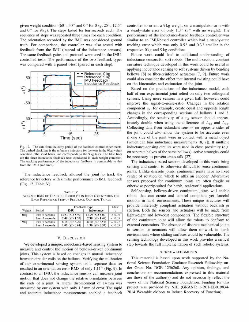
Fig. 12. The data from the early period of the feedback control experiments.The dashed black line is the reference trajectory for the tests in the 0 kg weightcondition. The solid black line corresponds to the 9 kg tests. The blue linesare the three inductance-feedback tests conducted in each weight condition.The tracking performance of the inductance feedback is comparable to thatfrom the IMU (red lines).
The inductance feedback allowed the joint to track thereference trajectory with similar performance to IMU feedback(Fig. 12, Table V).
TABLE VAVERAGE RMS OF TRACKING ERROR (◦) IN JOINT ORIENTATION FOR
EACH REFERENCE STEP OF FEEDBACK CONTROL TRIALS
Feedback Type t-testWeight Period IMU Inductance p0 kg First 5 seconds 13.53 (SD 5.99) 13.79 (SD 6.02) < 0.05
Last 5 seconds 2.48 (SD 1.55) 2.98 (SD 1.46) < 0.059 kg First 5 seconds 8.18 (SD 3.70) 8.10 (SD 3.55) = 0.27
Last 5 seconds 1.02 (SD 0.61) 1.30 (SD 0.55) < 0.05
V. DISCUSSION
We developed a unique, inductance-based sensing system tomeasure and control the motion of bellows-driven continuumjoints. This system is based on changes in mutual inductancebetween circular coils on the bellows. Verifying the calibrationof our experimental sensing system on a separate data setresulted in an orientation error RMS of only 1.11 ◦ (Fig. 9). Incontrast to an IMU, the inductance sensors can measure jointmotion that does not change the relative orientation betweenthe ends of a joint. A lateral displacement of 14 mm wasmeasured by our system with only 1.3 mm of error. The rapidand accurate inductance measurements enabled a feedback
controller to orient a 9 kg weight on a manipulator arm witha steady-state error of only 1.3 ◦ (3 ◦ with no weight). Theperformance of the inductance-based feedback controller wassimilar to an IMU-based controller which had a steady-statetracking error which was only 0.5 ◦ and 0.3 ◦ smaller in therespective 0 kg and 9 kg conditions.
Future work could lead to additional understanding ofinductance sensors for soft robots. The multi-section, constantcurvature technique developed in this work could be useful inapplying inductance sensing to soft systems driven by bendingbellows [8] or fiber-reinforced actuators [7, 9]. Future workcould also consider the effect that internal twisting could haveon the kinematics and estimation of the joint.
Based on the predictions of the inductance model, eachhalf of our experimental joint relied on only two orthogonalsensors. Using more sensors in a given half, however, couldimprove the signal-to-noise-ratio. Changes in the rotationcomponent va, for example, create equal and opposite lengthchanges in the corresponding sections of bellows 1 and 3.Accordingly, the sensitivity of a va sensor should approx-imately double when using the difference of L1a and L3a.Collecting data from redundant sensors on opposite sides ofthe joint could also allow the system to be accurate evenif one side of the joint were in contact with a metal object(which can bias inductance measurements [8, 7]). If multipleinductance-sensing circuits were used in close proximity (e.g.on separate halves of the same bellows), active strategies couldbe necessary to prevent cross-talk [27].
The inductance-based sensors developed in this work bringsensing and control to otherwise difficult-to-sense continuumjoints. Unlike discrete joints, continuum joints have no fixedcenter of rotation on which to affix an encoder. Alternativesensors proposed for continuum joints are often fragile orotherwise poorly-suited for harsh, real-world applications.
Self-sensing, bellows-driven continuum joints will enablerobots that can create and control compliant yet forcefulmotions in harsh environments. These unique structures willprovide inherently compliant actuation without backlash orstiction. Both the sensors and actuators will be made fromlightweight and low-cost components. The flexible structureof the continuum joint will allow the robots to conform toexternal constraints. The absence of discrete mechanical jointsin sensors or actuators will allow them to work in harshenvironments where sliding surfaces would be vulnerable. Thesensing technology developed in this work provides a criticalstep towards the full implementation of such robotic systems.
ACKNOWLEDGMENTS
This material is based upon work supported by the Na-tional Science Foundation Graduate Research Fellowship un-der Grant No. DGE 1256260. Any opinion, findings, andconclusions or recommendations expressed in this materialare those of the author(s) and do not necessarily reflect theviews of the National Science Foundation. Funding for thisproject was provided by NIH (GRANT: 1-R01-EB019834-2014 Wearable eMbots to Induce Recovery of Function).

REFERENCES
[1] Thomas F. Allen, Gabriel Hein, and Kevin Albert.Constant-curvature continuum manipulator kinematics.Under Review.
[2] Morteza Amjadi, Ki-Uk Kyung, Inkyu Park, and MetinSitti. Stretchable, skin-mountable, and wearable strainsensors and their potential applications: A review. Ad-vanced Functional Materials, 2016.
[3] Keith Antonelli and Guy Immega. An extensible robotictentacle. Industrial Robot: An International Journal, 24(6):423–427, 1997. doi: 10.1108/01439919710192545.URL http://dx.doi.org/10.1108/01439919710192545.
[4] E. R. Bachmann, I. Duman, U. Y. Usta, R. B. McGhee,X. P. Yun, and M. J. Zyda. Orientation tracking for hu-mans and robots using inertial sensors. In ComputationalIntelligence in Robotics and Automation, 1999. CIRA’99. Proceedings. 1999 IEEE International Symposiumon, pages 187–194, 1999. doi: 10.1109/CIRA.1999.810047.
[5] M. Cianchetti, T. Ranzani, G. Gerboni, I. De Falco,C. Laschi, and A. Menciassi. Stiff-flop surgical manip-ulator: Mechanical design and experimental characteri-zation of the single module. In 2013 IEEE/RSJ Inter-national Conference on Intelligent Robots and Systems,pages 3576–3581, Nov 2013. doi: 10.1109/IROS.2013.6696866.
[6] Wyatt Felt and C David Remy. Smart braid: Air musclesthat measure force and displacement. In IntelligentRobots and Systems (IROS 2014), 2014 IEEE/RSJ Inter-national Conference on, pages 2821–2826. IEEE, 2014.
[7] Wyatt Felt, Khai Yi Chin, and C. David Remy. Con-traction sensing with smart braid McKibben muscles.Mechatronics, IEEE/ASME Transactions on, PP(99):1–1, 2015. ISSN 1083-4435. doi: 10.1109/TMECH.2015.2493782.
[8] Wyatt Felt, Michelle Suen, and C David Remy. Sens-ing the motion of bellows through changes in mutualinductance. In Intelligent Robots and Systems (IROS2016), 2016 IEEE/RSJ International Conference on.IEEE, 2016.
[9] Wyatt Felt, Khai Yi Chin, and C. David. Remy. Smartbraid feedback for the closed-loop control of soft roboticsystems. Soft Robotics (In Press), 2017.
[10] Festo. Bionic handling assistant, 2010. URL http://www.festo.com/cms/en corp/9655 10218.htm.
[11] Festo. BionicMotionRobot, Mar 2017. URL https://www.festo.com/group/en/cms/12747.htm.
[12] I Gaiser, R Wiegand, O Ivlev, A Andres, H Breitwieser,S Schulz, and G Bretthauer. Compliant robotics andautomation with flexible fluidic actuators and inflatablestructures. 2012.
[13] M. T. Gillespie, C. M. Best, and M. D. Killpack. Simul-taneous position and stiffness control for an inflatablesoft robot. In 2016 IEEE International Conference onRobotics and Automation (ICRA), pages 1095–1101, May
2016. doi: 10.1109/ICRA.2016.7487240.[14] Teichert Systemtechnik GmbH. Innovative cable-like-
shape-sensor, Accessed April 2017. URL http://www.tst-inno.de/en/SAC.html.
[15] G. Granosik and J. Borenstein. Integrated joint actuatorfor serpentine robots. Mechatronics, IEEE/ASME Trans-actions on, 10(5):473–481, Oct 2005. ISSN 1083-4435.doi: 10.1109/TMECH.2005.856222.
[16] Michael D Grissom, Vilas Chitrakaran, Dustin Dienno,Matthew Csencits, Michael Pritts, Bryan Jones, WilliamMcMahan, Darren Dawson, Chris Rahn, and Ian Walker.Design and experimental testing of the octarm soft robotmanipulator. In Defense and Security Symposium, pages62301F–62301F. International Society for Optics andPhotonics, 2006.
[17] Christoph Ledermann, Julien Mintenbeck, Yitao Ding,Hendrikje Pauer, and Heinz Worn. Closed-loop controlof a flexible instrument using an integrated FBG-basedshape sensor. In International Conference on AdvancedTechnology & Sciences (ICAT’15), 2015.
[18] A.D. Marchese, K. Komorowski, C.D. Onal, and D. Rus.Design and control of a soft and continuously deformable2D robotic manipulation system. In Robotics and Au-tomation (ICRA), 2014 IEEE International Conferenceon, pages 2189–2196, May 2014. doi: 10.1109/ICRA.2014.6907161.
[19] Franz Ernst Neumann. Allgemeine gesetze der in-duzierten elektrischen strme. pages 1–87, 1845.
[20] Jones Franklin D. Horton Holbrook L. Ryffel Henry H.Oberg, Erik. Machinery’s Handbook (29th Edition) &Guide to Machinery’s Handbook. Industrial Press, 2012.ISBN 978-0-8311-2901-9.
[21] Oberhauser, Chris at Texas Instruments. LDC SensorDesign, 2014. URL http://www.ti.com/lit/an/snoa930/snoa930.pdf.
[22] Tatsuyuki Ochi. A positioning system for mobile robotsusing symmetrical rotating laser beams. AdvancedRobotics, 4(3):217–222, 1989.
[23] R. S. Penning, J. Jung, N. J. Ferrier, and M. R. Zinn. Anevaluation of closed-loop control options for continuummanipulators. In Robotics and Automation (ICRA), 2012IEEE International Conference on, pages 5392–5397,2012. doi: 10.1109/ICRA.2012.6224735.
[24] Gianluca Rizzello, David Naso, Alexander York, and Ste-fan Seelecke. A self-sensing approach for dielectric elas-tomer actuators based on online estimation algorithms.IEEE/ASME Transactions on Mechatronics, 2016.
[25] Sina Sareh, Yohan Noh, Min Li, Tommaso Ranzani,Hongbin Liu, and Kaspar Althoefer. Macrobend opticalsensing for pose measurement in soft robot arms. SmartMaterials and Structures, 24(12):125024, 2015.
[26] StretchSense. Stretchsense evaluation kit datasheet, June2015. URL http://stretchsense.com/wp-content/uploads/2015/06/Stretch-Sensor-Datasheet.pdf.
[27] Texas Instruments. Application Report: Using MultipleSensors with LDC1000, 2014. URL http://www.ti.com/

lit/an/snoa924/snoa924.pdf.[28] C. To, T.L. Hellebrekers, and Yong-Lae Park. Highly
stretchable optical sensors for pressure, strain, andcurvature measurement. In Intelligent Robots and Sys-tems (IROS), 2015 IEEE/RSJ International Conferenceon, pages 5898–5903, Sept 2015. doi: 10.1109/IROS.2015.7354215.
[29] Ran Xu, Ali Asadian, Anish S Naidu, and Rajni V Patel.Position control of concentric-tube continuum robots us-ing a modified jacobian-based approach. In Robotics andAutomation (ICRA), 2013 IEEE International Conferenceon, pages 5813–5818. IEEE, 2013.
[30] Ali Yassin, Youssef Nasser, Mariette Awad, Ahmed Al-Dubai, Ran Liu, Chau Yuen, and Ronald Raulefs. Recentadvances in indoor localization: A survey on theoreticalapproaches and applications. IEEE CommunicationsSurveys & Tutorials, 2016.
[31] Alan Yates and Jeremy Selan. Positional tracking systemsand methods, May 12 2016. US Patent 20,160,131,761.
[32] Huichan Zhao, Kevin O’Brien, Shuo Li, and Robert F.Shepherd. Optoelectronically innervated soft pros-thetic hand via stretchable optical waveguides. Sci-ence Robotics, 1(1), 2016. doi: 10.1126/scirobotics.aai7529. URL http://robotics.sciencemag.org/content/1/1/eaai7529.