an in-lab grid for the development of energy storage for...
TRANSCRIPT
AN IN-LAB GRID FOR THE DEVELOPMENT OF ENERGY STORAGE FOR USE WITH WIND ENERGY
Professors: Annette von Jouanne, Ted Brekken, Alex Yokochi
Students: Eunice Naswali, Hai Yue Han, David Naviaux, Chianna Alexander, Alex Bistrika
1

Outline• Project Overview
• Goals• In-lab grid schematic• In-lab grid components
• Simulation Results
• Energy Storage Control
• Energy Storage System• Super capacitors
2

Goals• Optimize wind energy production and improve
predictability of wind power using forecasting and large-scale energy storage.• Variability of wind limits wind power penetration and increases its
cost.
• Initial Goal: Enable a wind farm output instantaneous power within 4% per unit of forecast, 90 % of the time.
• New Goal: Target to conform to BPA’s persistent deviation definition (and perhaps include ramps as well).
• Number of hours within 4 or more consecutive hours the deviation between the generation and the scheduled exceeds both (i) 15% of the schedule for the hour and (ii) 20 MW in each hour.
3

Goals
4

IN-LAB GRID
5

In-lab Grid Schematic
6

In-lab Grid Components• Control Computer
• dSPACE control• 120 kVA AWG programmable source (wind farm)
• Connection Board• Point of common coupling
• WRIG hydro and pumped hydro source• Slow response energy source
• Energy Storage System• Zn Br flow cell battery
• 25 kW / 50 kWhr, medium response time, 75% efficiency• Maxwell supercapacitors
• 25 kW, fast response time, 90% efficiency
7

Control Computer
dSPACE/ControlDesk Control
Central point for control, data acquisition and display.
Automated synchronization and closing of rotational generation.
8

AWG
120 kVA arbitrary waveform generator.
Programmed for actual wind farm output power.
9

Connection Board
Point of common coupling.
SEL 751A relays for control and data acquisition.
10

WRIG
80 kW WRIG with DC field excitation to act like a synchronous generator.
Emulate hydro generation and pumped hydro storage.
11

Energy Storage System 1
ZnBr flow cell battery.
25 kW / 50 kWhr, medium response time, 75% round trip efficiency.
12

Energy Storage System 2
Maxwell supercapacitors.
25 kW, fast response time, 90% efficiency.
13

SIMULATION RESULTS
14

Initial Simulation Results• Three energy storage mediums
• Pumped hydro• Large energy capacity• Medium response
• ZnBr flow cell battery• Medium energy capacity• Medium-fast response
• Supercapacitors• Low energy capacity• Fast response
15

Simulation
16
Matlab/Simulink energy storage and control

Energy Storage Control
Single energy storage command is bandpass filtered to split the power command into three and passed to respective control mediums.
17
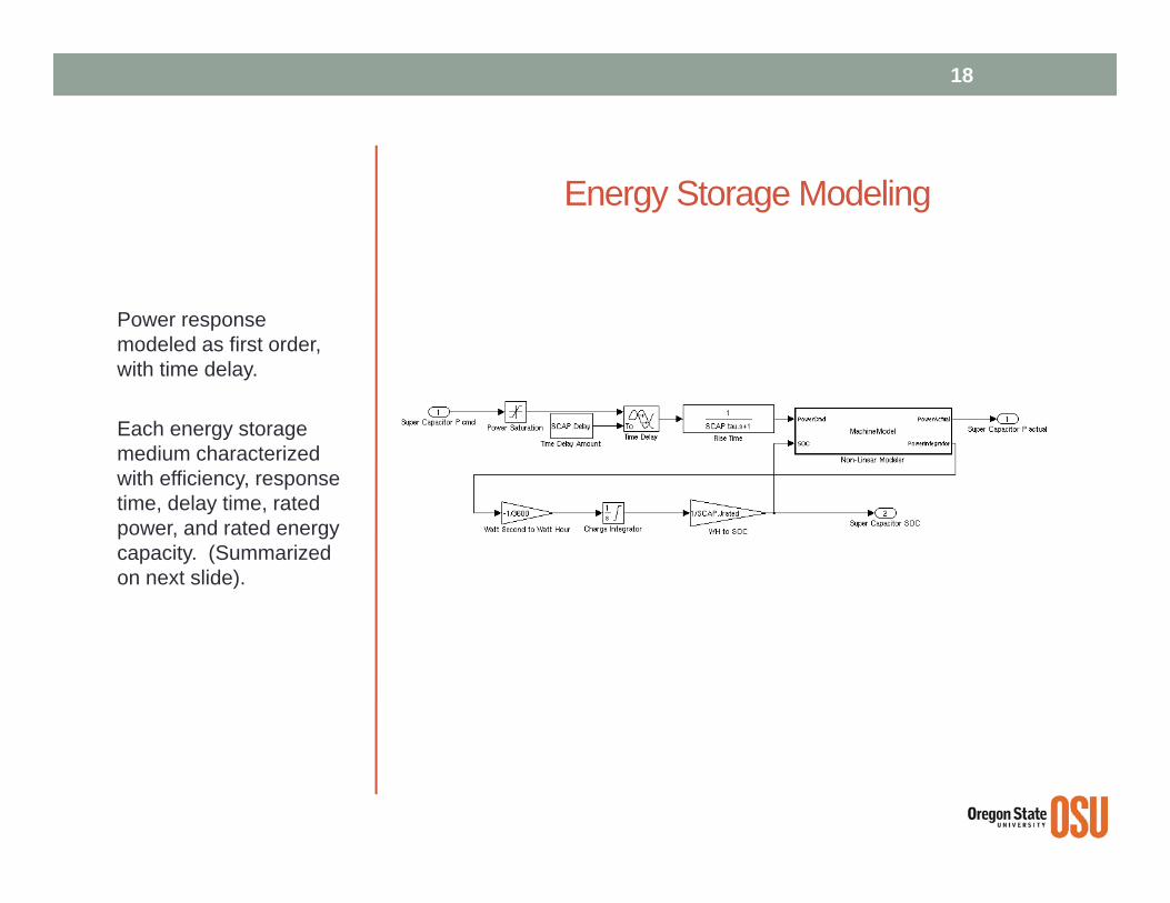
Energy Storage Modeling
Power response modeled as first order, with time delay.
Each energy storage medium characterized with efficiency, response time, delay time, rated power, and rated energy capacity. (Summarized on next slide).
18

Energy Storage Simulation ParametersTime constant
Delay Prated (pu)
Jrated(pu-hrs)
Efficiency (one-way)
Flow cell 1.2 s 1 s 0.300 0.68 0.85Supercapacitors 1 ms 0.1 ms 0.300 0.001 0.92Pumped hydro 20 s 10 s 0.188 150 0.90
19
Pumped hydro power and energy rating determined as a pro-rated share of BPA’s pumped hydro capacity (for one large wind farm).

Meeting the Forecast with Energy StorageIn the top plot, there is an error between the wind plant output and the forecasted output.
In the middle plot, the energy storage system supplements the wind plant output such that the combined wind plant and energy storage system output meets the forecast most of the time.
In the bottom plot, the energy storage output matches command most of the time. Except for ramps!
20

Power by Energy Storage MediumZnBr battery takes medium scale response.
Supercaps take fast response.
Pumped hydro takes slow response.
21

SOC by Energy Storage MediumAdequate amount of charge capacity is a big driver of energy storage cost.
The necessary amount of charge capacity is dependent on the characteristics of the energy storage medium (e.g., response time, efficiency) and how it is controlled.
22

Energy Storage Control – Next Steps• Approach: borrow AGC (Automated Generation Control) concepts
and apply it to a wind farm. This has benefits over the previously shown control in that it presents a robust and widely accepted framework for the control of multiple sources.
• The combined wind farm and energy storage plant becomes the “area,” and the forecast output becomes the inter-area schedule.
• The wind farm output becomes a negative load.
• Energy storage units can be controlled under frequency control for fast response and frequency regulation (supercapacitors), and also under AGC to regulate scheduled power and frequency errors.
• The AGC scheme can be modified to included considerations of energy storage health, response time, and SOC.
23

Energy Storage Control – Next Steps
24
Degrees of freedom: how do different energy storage mediums respond to both frequency and area control error (ACE)?
After flow battery and supercapacitors are integrated in this way, it will be expanded to pumped hydro.

SUPERCAPACITORS
25

Supercapacitor Storage System• Specifications
• Power – 25 kW• Pulse duration – 90 s (to minimize access of battery)• Vmax – 290 V• Vmin – 155 V• Temperature – room• Life ~ 10 years
• Size• 18x 166F/48.6V modules, each module consists 18x 3000F/2.7V
maxwell supercapacitors
26

Supercapacitor Storage SystemEquations Module
27
1. Determine capacitance of the system
2. Determine number of modules in series and parallel
166F 48.6V module

Supercapacitor model
• terminals, contacts, electrodes, electrolyte, ..• Racc, Cacc
• transmission line behavior• R/n, C/n
• self discharge due to leakage• Rlk

Supercapacitor testing• Characterization tests
• Constant Current - capacitance and ESR• Constant Power – specific power and specific energy• Leakage – losses during inactivity• Self-Discharge - losses during inactivity• Energy Efficiency • Electrochemical Impedance Spectrometry – capacitance,
resistances in the model
• Lifetime tests• Cycle-life

THANK YOU
30