an improved error correction algorithm for multicasting
TRANSCRIPT

NORTH-WEST UNIVERSITY
An improved error correction
algorithm for multicasting over LTE
networks Dissertation submitted in fulfilment of the requirements for the degree
Master of Engineering in Computer and Electronic Engineering at the
Potchefstroom Campus of the North-West University
JM Cornelius
21099383
Supervisor: Prof. ASJ Helberg
November 2013
The financial assistance of the National Research Foundation (NRF) towards this research is hereby acknowledged.
Opinions expressed and conclusions arrived at, are those of the author and are not necessarily to be attributed to the
NRF.
An improved error correction algorithm for multicasting over LTE networks
ii
Declaration
I, Johannes Mattheüs Cornelius, hereby declare that the dissertation entitled “An improved
error correction algorithm for multicasting over LTE networks” is my own work and has
not already been submitted to any other university or institution for examination.
JM Cornelius
Student number: 21099383
Signed on the 15th day of November 2013 at Potchefstroom

An improved error correction algorithm for multicasting over LTE networks
iii
Acknowledgements
To all who made this possible,
my dedicated supervisor, Prof. Albert Helberg,
my loving parents and family,
my supportive friends,
the Telkom Centre of Excellence,
everyone in the Telenet-research group,
my Almighty Saviour,
my sincerest gratitude.
I am humbled by the grace I have received.
An improved error correction algorithm for multicasting over LTE networks
iv
Abstract
Multicasting in Long-Term Evolution (LTE) environments poses several challenges if it is to
be reliably implemented. Neither retransmission schemes nor Forward Error Correction
(FEC), the traditional error correction approaches, can be readily applied to this system of
communication if bandwidth and resources are to be used efficiently. A large number of
network parameters and topology variables can influence the cost of telecommunication in
such a system. These need to be considered when selecting an appropriate error correction
technique for a certain LTE multicast deployment. This dissertation develops a cost model to
investigate the costs associated with over-the-air LTE multicasting when different error
correction techniques are applied. The benefit of this simplified model is an easily
implementable and fast method to evaluate the communications costs of different LTE
multicast deployments with the application of error correction techniques.
Keywords: Long-Term Evolution, MBSFN, multicasting, error correction

An improved error correction algorithm for multicasting over LTE networks
v
Table of Contents
DECLARATION .................................................................................................................................................. II
ACKNOWLEDGEMENTS ...................................................................................................................................III
ABSTRACT ...................................................................................................................................................... IV
TABLE OF CONTENTS ....................................................................................................................................... V
LIST OF FIGURES ........................................................................................................................................... VIII
LIST OF TABLES .............................................................................................................................................. IX
LIST OF ABBREVIATIONS ................................................................................................................................. X
CHAPTER 1 – INTRODUCTION .......................................................................................................................... 1
INTRODUCTION .......................................................................................................................................... 1 1.1
BACKGROUND ........................................................................................................................................... 1 1.2
PROBLEM STATEMENT AND MOTIVATION ....................................................................................................... 2 1.3
HYPOTHESIS .............................................................................................................................................. 4 1.4
CLARIFICATION OF HYPOTHESIS ..................................................................................................................... 4 1.5
JUSTIFICATION FOR STUDY ............................................................................................................................ 5 1.6
RESEARCH GOALS ....................................................................................................................................... 6 1.7
RESEARCH METHODOLOGY .......................................................................................................................... 7 1.8
Verification and Validation ............................................................................................................. 10 1.8.1
DISSERTATION OVERVIEW .......................................................................................................................... 10 1.9
CHAPTER 2 – LITERATURE STUDY ................................................................................................................... 11
INTRODUCTION ........................................................................................................................................ 11 2.1
LONG-TERM EVOLUTION ........................................................................................................................... 11 2.2
MULTICASTING IN LTE ENVIRONMENTS ........................................................................................................ 13 2.3
IP Multicasting ................................................................................................................................ 13 2.3.1
Evolved-MBMS ................................................................................................................................ 16 2.3.2
ERROR CORRECTION IN MBSFN.................................................................................................................. 17 2.4
Retransmission schemes ................................................................................................................. 17 2.4.1
Forward error correction ................................................................................................................. 18 2.4.2
Error correction challenges in MBSFN ............................................................................................. 19 2.4.3
OVERVIEW OF THE MBSFN ARCHITECTURE ................................................................................................... 20 2.5
CONCLUSION ........................................................................................................................................... 22 2.6

An improved error correction algorithm for multicasting over LTE networks
vi
CHAPTER 3 – MATHEMATICAL MODEL ........................................................................................................... 23
INTRODUCTION ........................................................................................................................................ 23 3.1
MBSFN TOPOLOGY ................................................................................................................................. 24 3.2
COST OVER THE AIR INTERFACE .................................................................................................................... 26 3.3
ERROR CORRECTION COSTS ......................................................................................................................... 30 3.4
ARQ costs ........................................................................................................................................ 30 3.4.1
ARQ-FEC Combination costs............................................................................................................ 31 3.4.2
MODEL VARIABLES ................................................................................................................................... 32 3.5
CONCLUSION ........................................................................................................................................... 34 3.6
CHAPTER 4 – RESULTS .................................................................................................................................... 35
INTRODUCTION ........................................................................................................................................ 35 4.1
TEST 1: USER POPULATION VS. MBSFN COST ............................................................................................... 36 4.2
Test scope and purpose................................................................................................................... 36 4.2.1
Simulation setup ............................................................................................................................. 36 4.2.2
Test results ...................................................................................................................................... 37 4.2.3
Discussion ....................................................................................................................................... 41 4.2.4
Validation ........................................................................................................................................ 42 4.2.5
TEST 2: PACKET LOSS RATE VS. MBSFN COST............................................................................................... 43 4.3
Test Scope and Purpose .................................................................................................................. 43 4.3.1
Simulation Setup ............................................................................................................................. 43 4.3.2
Test Results ..................................................................................................................................... 44 4.3.3
Discussion ....................................................................................................................................... 48 4.3.4
TEST 3: FEC OVERHEAD VS. MBSFN COST .................................................................................................. 50 4.4
Test Scope and Purpose .................................................................................................................. 50 4.4.1
Simulation Setup ............................................................................................................................. 50 4.4.2
Test Results ..................................................................................................................................... 51 4.4.3
Discussion ....................................................................................................................................... 55 4.4.4
TEST 4: USER DISTRIBUTION VS. MBSFN COST ............................................................................................. 57 4.5
Test scope and purpose................................................................................................................... 57 4.5.1
Simulation Setup ............................................................................................................................. 57 4.5.2
Test Results ..................................................................................................................................... 58 4.5.3
Discussion ....................................................................................................................................... 62 4.5.4
CHAPTER 5 – VERIFICATION AND VALIDATION .............................................................................................. 64
INTRODUCTION ........................................................................................................................................ 64 5.1
VERIFICATION .......................................................................................................................................... 65 5.2
Simulation scenario ......................................................................................................................... 65 5.2.1
An improved error correction algorithm for multicasting over LTE networks
vii
Modelled results ............................................................................................................................. 65 5.2.2
Calculated results ............................................................................................................................ 66 5.2.3
5.2.3.1 ARQ cost ................................................................................................................................................. 68
5.2.3.2 HARQ cost .............................................................................................................................................. 69
5.2.3.3 FEC Cost ................................................................................................................................................. 70
Conclusion ....................................................................................................................................... 71 5.2.4
VALIDATION ............................................................................................................................................ 72 5.3
Simulation scenario ......................................................................................................................... 72 5.3.1
Result sets ....................................................................................................................................... 72 5.3.2
Qualitative comparison ................................................................................................................... 74 5.3.3
Correlation coefficient..................................................................................................................... 75 5.3.4
5.3.4.1 The Pearson correlation coefficient ....................................................................................................... 75
5.3.4.2 ARQ curve .............................................................................................................................................. 75
5.3.4.3 HARQ curve ............................................................................................................................................ 76
5.3.4.4 FEC curve................................................................................................................................................ 77
5.3.4.5 Total correlation .................................................................................................................................... 79
Conclusion ....................................................................................................................................... 79 5.3.5
CHAPTER 6 – CONCLUSION ............................................................................................................................ 80
INTRODUCTION ........................................................................................................................................ 80 6.1
RESEARCH HYPOTHESIS .............................................................................................................................. 80 6.2
CHAPTER REVIEW AND RESEARCH OBJECTIVES ............................................................................................... 82 6.3
CONCLUSIONS ......................................................................................................................................... 83 6.4
SIGNIFICANT RESULTS ............................................................................................................................... 83 6.5
FUTURE WORK AND RECOMMENDATIONS ...................................................................................................... 85 6.6
REFERENCES ................................................................................................................................................... 86
APPENDIX A – CONFERENCE CONTRIBUTIONS FROM THIS DISSERTATION ..................................................... 88
A.1 WORK IN PROGRESS: AN IMPROVED ERROR CORRECTION ALGORITHM FOR MULTICASTING OVER LTE NETWORKS ............ 88
A.2 A SIMPLIFIED COST MODEL TO EVALUATE ERROR HANDLING TECHNIQUES FOR MULTICASTING OVER LTE ....................... 91

An improved error correction algorithm for multicasting over LTE networks
viii
List of Figures
FIGURE 1: RESEARCH METHODOLOGY .............................................................................................................................. 9
FIGURE 2: UNICAST COMMUNICATION ........................................................................................................................... 14
FIGURE 3: BROADCAST COMMUNICATION ...................................................................................................................... 14
FIGURE 4: MULTIPLE UNICAST COMMUNICATION ............................................................................................................. 15
FIGURE 5: MULTICAST COMMUNICATION ....................................................................................................................... 15
FIGURE 6: E-MBMS (MBSFN) ARCHITECTURE ............................................................................................................... 21
FIGURE 7: A HEXAGONAL GRID OF CELLS ......................................................................................................................... 24
FIGURE 8: RESOURCE EFFICIENCY OF MBSFN DEPLOYMENTS ............................................................................................. 28
FIGURE 9: USER POPULATION VS. MBSFN COST - CASE 1, K = 2........................................................................................ 37
FIGURE 10: USER POPULATION VS. MBSFN COST - CASE 1, K = 19. .................................................................................. 38
FIGURE 11: USER POPULATION VS. MBSFN COST – CASE 3, K = 2. .................................................................................... 39
FIGURE 12: USER POPULATION VS. MBSFN COST - CASE 3, K = 19. .................................................................................. 40
FIGURE 13: PACKET LOSS RATE VS. MBSFN COST – CASE 1, K = 2, FEC = 5% ..................................................................... 44
FIGURE 14: PACKET LOSS RATE VS. MBSFN COST – CASE 1, K = 2, FEC = 15% ................................................................... 44
FIGURE 15: PACKET LOSS RATE VS. MBSFN COST – CASE 1, K = 19, FEC = 5% ................................................................... 45
FIGURE 16: PACKET LOSS RATE VS. MBSFN COST – CASE 1, K = 19, FEC = 15% ................................................................. 45
FIGURE 17: PACKET LOSS RATE VS. MBSFN COST – CASE 3, K = 2, FEC = 5% ..................................................................... 46
FIGURE 18: PACKET LOSS RATE VS. MBSFN COST – CASE 3, K = 19, FEC = 5% ................................................................... 46
FIGURE 19: PACKET LOSS RATE VS. MBSFN COST – CASE 3, K = 2, FEC = 15% ................................................................... 47
FIGURE 20: PACKET LOSS RATE VS. MBSFN COST – CASE 3, K = 19, FEC = 15% ................................................................. 47
FIGURE 21: FEC OVERHEAD VS. MBSFN COST – CASE 1, K = 2, PACKET LOSS RATE = 5% ...................................................... 51
FIGURE 22: FEC OVERHEAD VS. MBSFN COST – CASE 1, K = 2, PACKET LOSS RATE = 10% .................................................... 52
FIGURE 23: FEC OVERHEAD VS. MBSFN COST – CASE 1, K = 19, PACKET LOSS RATE = 5% .................................................... 53
FIGURE 24: FEC OVERHEAD VS. MBSFN COST – CASE 1, K = 19, PACKET LOSS RATE = 10% .................................................. 54
FIGURE 25: USER DISTRIBUTION VS. MBSFN COST – CASE 1, PACKET LOSS RATE = 5%, FEC OVERHEAD = 5% .......................... 58
FIGURE 26: USER DISTRIBUTION VS. MBSFN COST – CASE 1, PACKET LOSS RATE = 25%, FEC OVERHEAD = 5%. ....................... 59
FIGURE 27: USER DISTRIBUTION VS. MBSFN COST – CASE 1, PACKET LOSS RATE = 5%, FEC OVERHEAD = 15%. ....................... 60
FIGURE 28: USER DISTRIBUTION VS. MBSFN COST – CASE 3, PACKET LOSS RATE = 5%, FEC OVERHEAD = 5%. ......................... 61
FIGURE 29: OWN RESULTS (MODELLED) COMPARED TO PUBLISHED RESULTS IN [8]................................................................. 73

An improved error correction algorithm for multicasting over LTE networks
ix
List of Tables
TABLE 1: MATHEMATICAL SYMBOLS .............................................................................................................................. 23
TABLE 2: SPECTRAL EFFICIENCY FOR MBSFN DEPLOYMENTS .............................................................................................. 27
TABLE 3: MODEL VARIABLES ........................................................................................................................................ 33
TABLE 4: MODELLED RESULTS ...................................................................................................................................... 65
TABLE 5: SPECTRAL EFFICIENCY FOR MBSFN DEPLOYMENTS .............................................................................................. 66
TABLE 6: MODELLED RESULTS COMPARED TO CALCULATED RESULTS .................................................................................... 71
TABLE 7: OWN RESULTS (MODELLED) COMPARED TO PUBLISHED RESULTS ............................................................................. 72
An improved error correction algorithm for multicasting over LTE networks
x
List of Abbreviations
3GPP - The 3rd Generation Partnership Project
4G - 4th Generation Radio Technologies
ARQ - Automatic Repeat reQuest
CP - Control Plane
e-BM-SC - Evolved Broadcast Multicast Service Centre
e-MBMS - Evolved MBMS
e-NB - Evolved Node-B
e-UTRAN - Evolved Universal Terrestrial Radio Access Network
FEC - Forward error correction
GW - Gateway
HSDPA - High-Speed Downlink Packet Access
HSUPA - High-Speed Uplink Packet Access
IP - Internet Protocol
ISD - Inter-Site Distance
LTE - Long-Term Evolution
MBMS - Multimedia Broadcast Multicast Services
MBSFN - MBMS Single Frequency Network OR Multicast Broadcast Single
Frequency Network
MCCH - Multicast Control Channel
MCE - Multicast Coordination Equipment
MIMO - Multiple-Input and Multiple-Output
MME - Mobility Management Entity
MTCH - Multicast Traffic Channel

An improved error correction algorithm for multicasting over LTE networks
xi
OFDMA - Orthogonal Frequency-Division Multiple Access
SC-FDMA - Single-Carrier Frequency-Division Multiple Access
SFN - Single Frequency Network
SINR - Signal-to-Interference plus Noise Ratio
UE - User Equipment
UP - User Plane
VoIP - Voice over Internet Protocol
An improved error correction algorithm for multicasting over LTE networks
- 1 -
1 Introduction
Chapter 1 – Introduction
Introduction 1.1
In this chapter we introduce the research problem and domain by providing the theoretical
background leading to our hypothesis. A specific problem statement is derived from this
background, providing motivation for the research done. This is summarised into a
hypothesis, which is used throughout the document as a framework to evaluate the
adherence of the research to its objectives. The chapter also includes a justification for the
study. Research goals are stated, followed by an elaboration on the research methodology
used. This chapter ends with a structural overview of the full dissertation.
Background 1.2
Long-Term Evolution (LTE) is the 3rd Generation Partnership Project’s (3GPP’s) answer to
achieving the realisation of 4th Generation (4G) radio technologies. It greatly improves the
speed, throughputs and capacity of mobile networks over its predecessors. Importantly for
this study, multicast communication has been supported from the first release of LTE

An improved error correction algorithm for multicasting over LTE networks
- 2 -
specifications in the form of a Single Frequency Network (SFN) [1]. This method of
communication, when applied appropriately, significantly increases bandwidth efficiency and
decreases processing overhead. Multicasting is particularly suitable for the delivery of
multimedia content to a destination group of mobile receivers. The 3GPP describes a multi-
cell transmission service to implement multicast technology in LTE, termed the Multimedia
Broadcast Single Frequency Network (MBSFN). This is envisioned to be employed on a
large scale to support multimedia distribution over cellular networks [1], [2].
One aim of multicasting is to provide reliable, error-free transmission of data. To achieve
this, some form of error correction needs to be implemented. It turns out, however, that
error-free multicasting poses several implementation challenges [3]. The two main traditional
approaches to error correction are retransmission schemes and forward error correction
(FEC). In retransmission schemes lost packets are retransmitted by the source to the group
of mobile receivers. If FEC is used, the receiver relies on redundant data sent with the
original transmission to decode the source message, despite possible errors in the
transmission. When applied to multicast transmission, both approaches have a number of
advantages and disadvantages as discussed in detail in Chapter 2. Depending on the
network conditions, the selection of an error correction scheme can have a large influence
on the overall cost of communication. In fact, a vast number of network parameters and
topology variables need to be considered before an appropriate error correction scheme can
be drawn up for a specific multicast system. It is out of this observation that our problem
statement has been formulated.
Problem Statement and Motivation 1.3
The proposed research aims to develop an algorithm to improve error correction techniques
in MBSFN systems. Recent research ([3], [4], [5]), published in 2011 and the first quarter of
2012, has investigated the efficiency of different retransmission and FEC techniques in
MBSFN systems . Several researchers have quantified the effect of a number of network
parameters on the efficiency of error correction techniques (and their associated network
costs). However, no effort has yet been made to unify these studies into a systematic
approach that could help with the selection of the most effective technique given certain
network conditions.

An improved error correction algorithm for multicasting over LTE networks
- 3 -
Our integrated solution is to develop an algorithm that will take a broad spectrum of network
parameters as input conditions. These may include network topology, number of users,
density of user equipment and many others. As output, the developed algorithm would
provide an idea of what error correction scheme will be most effective for the network at
hand. It could, for example, help with the selection of an appropriate Raptor code for FEC
under dynamic conditions. It should be noted that the goal is overall improvement and not
mathematical optimization of error correction techniques – the latter requiring rigorous
mathematical proofs.
Although error correction schemes have a broad range of applications across all spheres of
data-communication, the research proposed here will make a definite contribution to
multicasting in LTE environments. It will do so by specifically considering network conditions
that apply to MBSFN systems. Considering the fact that LTE was only approved in 2008 and
with deployment still in its initial stages, the actuality of the research is evident.

An improved error correction algorithm for multicasting over LTE networks
- 4 -
Hypothesis 1.4
Using a number of MBSFN network variables and the fundamental characteristics of basic
error correction techniques, we can create a mathematical model to select the lowest-cost
error correction scheme for the over-the-air interface of a specific MBSFN network under
specific conditions.
Clarification of hypothesis 1.5
The hypothesis is clarified by explaining the specific word choices:
“a number of…variables” - We create a mathematical cost
model for an MBSFN network that considers a selection of the most important
variables that influence network operation. Since we aim to create a simplified model,
we do not need to represent reality in an exact manner – which would require
incorporating an exhaustive list of variables. The model will be shown to model the
real world closely enough to make meaningful conclusions about network costs.
“the fundamental characteristics” - We model the fundamental
operation of error correction schemes and make a number of assumptions to simplify
the process. Advanced features of the different error correction techniques, such as
network sensing, handshaking, etc. fall beyond the scope of the research [6], [7].
“basic error correction techniques” - The model incorporates the two
main traditional approaches to error correction, namely retransmission schemes in
the form of Automatic Repeat-reQuest (ARQ) and FEC, and a combination of the two
schemes.
“we can create a mathematical model” - This is the hypothesis we set out
to prove. The model is a series of mathematical computations on a collection of input
variables and not merely theoretical.
“to select the lowest-cost…scheme” - The model does not propose a
new error correction scheme – it provides the necessary tools to select an
appropriately low-cost scheme for a given scenario.
“for the over-the-air interface” - The largest contributor towards
overall communication costs in a multicast transmission over an LTE network, is the
cost of transmission over the air interface (the interface between the e-NB and the

An improved error correction algorithm for multicasting over LTE networks
- 5 -
UE – see Chapter 2 Section 2.5). According to [5] it accounts for around 80% to 90%
of the total cost and is therefore a suitable approximation of the total cost for the
multicast transmission. We consider only this interface in our model to simplify
implementation, under the assumption that results can be extrapolated to include to
whole network with 80%-90% accuracy.
“of a specific MBSFN network” - The model can simulate the
telecommunications cost of a variety of MBSFN network deployments and, given a
set of variables describing a specific MBSFN network, make a selection of the
lowest-cost error correction scheme for that system.
“under specific conditions” - The model also takes as input a
series of variables describing the conditions apart from the specific network set-up,
such as loss conditions, user mobility, etc.
Justification for study 1.6
A comprehensive literature survey revealed many opportunities for new research in this
area. No documented results evaluating the costs associated with different error correction
schemes over the air interface of an MBSFN network could be found. While the authors of
[8] did consider the error correction costs of an MBSFN transmission over all the network
interfaces, their simplified network model couldn’t be mathematically duplicated and they
have suggested the inclusion of more variables into a unified mathematical model as
possible new research [8], [9], [10].

An improved error correction algorithm for multicasting over LTE networks
- 6 -
Research Goals 1.7
The proposed research will address the following objectives:
Gain a thorough understanding of the LTE environment, with specific reference to
multicasting and MBSFN systems.
Study and quantify the effect of different network parameters on the reliability of
multicast communication.
Investigate different error correction schemes appropriate for MBSFN systems.
Quantify the relationship between the efficiency of a selected scheme and network
conditions.
Develop a systematic approach (an algorithm) to improve the selection of error
correction scheme under any given set of network conditions.
Compare results of the algorithmic approach to existing methods and validate that it
indeed led to improvement.
Verify the algorithmic approach by showing that it is mathematically rigorous and
plausible.

An improved error correction algorithm for multicasting over LTE networks
- 7 -
Research Methodology 1.8
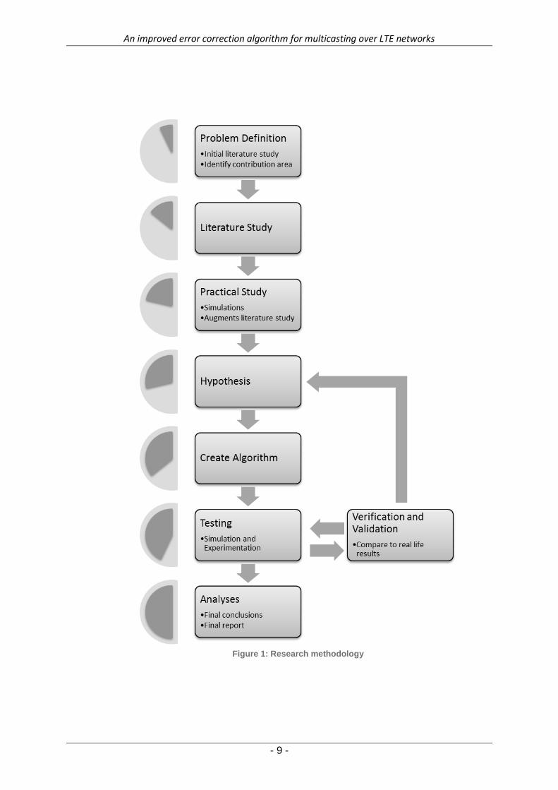
The first step in the research process is to define the problem that the study will seek to
address. This is done through an initial literature study. During this stage of the process a
technical understanding of the study field is not yet required - the literature study only serves
to identify a gap in current knowledge of the field and the possibility of a meaningful
contribution that the research project might make.
Once a suitable problem has been defined, an in-depth literature study commences. The
study must cover all aspects of LTE environments with regards to multicasting. Network
parameters that might affect reliability of communication should be identified in this step. The
literature study will also provide the researcher with a clear understanding of error correction
schemes (as appropriate for multicast communication), their advantages, disadvantages and
operation.
An additional step that will be required in this research project is a practical study
(simulations) to further investigate certain concepts from the literature study. For example,
the only way to truly grasp the effect of network parameters on reliability of communication is
to simulate said network conditions. This step supports and augments the literature study (it
does not yet test any hypotheses).
The next step is to formulate a hypothesis based on the technical and theoretical knowledge
gained in the literature and practical study. It will consider network variables and the effect
they have on the capabilities of error correcting schemes in an MBSFN system. The
hypothesis should describe a proposed method to select error correction schemes under
dynamic network conditions.
In conjunction with the hypothesis, an algorithm is now created - a quantified, systematic
approach for selection of an error correction scheme (including coding methods) given the
network conditions of an MBSFN system.
An improved error correction algorithm for multicasting over LTE networks
- 8 -
Next, the developed algorithm undergoes rigorous testing through simulation and
experimentation. Its capabilities given any set of network conditions will be evaluated.
Shortcomings or oversights in the technique are identified in this step, while changes to the
algorithm are made accordingly.
The process of verification and validation occurs concurrently with the testing phase. The
accuracy of the simulation is verified by comparing experimentation results to real life
results. A detailed discussion of the verification and validation process appears in
Section 1.9.1 below.
A detailed analysis of the final results completes the research process. Conclusions are
drawn with regards to the achievement of initial research objectives, perceived shortcomings
and strengths and the applicability of results in real-world scenarios.
A diagram illustrating this process appears on the next page.
An improved error correction algorithm for multicasting over LTE networks
- 9 -
Figure 1: Research methodology
An improved error correction algorithm for multicasting over LTE networks
- 10 -
Verification and Validation 1.8.1
Once the mathematical model has been created, the results are verified by proving that they
have been achieved through a mathematically rigorous process. To do this, we identify a
subset of data and use it to duplicate a small simulation scenario performed by our model.
This subset of data is used to generate a result set by performing step-by-step mathematical
calculations by hand similar to the computer processes implemented by our mathematical
model. The results are compared to those generated by a computer (the mathematical
model) to prove that the programming and implementation was correct and the model is
accurate.
The verification phase is followed by the validation phase by performing tests similar to those
in published research documents and comparing the results. A simulation scenario is set up
according to the same specifications as a published author. A correlation coefficient is
computed between the result sets (own and published) to show that the underlying theories
have been correctly applied to address the issues highlighted in the problem statement.
Dissertation Overview 1.9
The rest of this document is structured as follows. A detailed literature study appears in
Chapter 2, providing the theoretical background for the dissertation. This is followed by an
explanation of our mathematical model in Chapter 3. The model’s abilities are illustrated in a
series of results in Chapter 4, followed by its verification and validation in Chapter 5. We
conclude this study in Chapter 6 by evaluating our adherence to stated goals and making
meaningful recommendations. The document ends with a list of references. Conference
contributions from this dissertation appear in the appendix.
An improved error correction algorithm for multicasting over LTE networks
- 11 -
2 Literature Study
Chapter 2 – Literature Study
Introduction 2.1
This chapter expands upon the problem and research domain by providing background on
LTE environments, multicasting in LTE environments and error correction techniques
appropriate for multicast environments.
Long-Term Evolution 2.2
The 3rd Generation Partnership Project (3GPP) first introduced Long-Term Evolution (LTE) in
their Release 8 specification. It is designed to be a significant step towards the development
of 4th generation (4G) radio technologies aiming to improve the speed, throughputs and
capacity of mobile communications [1]. In fact, when first approved in 2008 LTE provided a
peak downlink bitrate of 144Mbps and a peak uplink bitrate of 57Mbps. In both cases this
was a factor-of-10 improvement in performance over its predecessor, the Release 6 HSDPA
(High-Speed Downlink Packet Access) and HSUPA (High-Speed Uplink Packet Access) [2].
To achieve this remarkable technological enhancement, LTE proposes several novel
approaches to mobile communication systems. All types of traffic in an LTE network are
carried by IP (Internet Protocol) packets. This include voice traffic, for which a form of Voice
over IP (VoIP) is used [1]. As explained in [11], several changes to the physical layer are

An improved error correction algorithm for multicasting over LTE networks
- 12 -
also introduced. Performance and robustness are greatly improved by the introduction of
multiple-antenna transmission and reception. This method is referred to as MIMO (or
Multiple-Input, Multiple-Output). Furthermore, Orthogonal Frequency Division Multiple
Access (OFDMA) is used as modulation scheme for downlink transmission and Single
Carrier Frequency Division Multiple Access (SC-FDMA) for the uplink. Both these techniques
require the computation of many fast Fourier transforms and the corresponding digital signal
processing power to perform them. For this reason, even though the usage of these multiple
access schemes has been considered before, the cost of processing power for mobile
applications has only recently been sufficiently reduced to viably implement OFDMA and
SC-FDMA [2]. Lastly, and most notably for purposes of this research document, multicast is
supported from the very first release of LTE specifications [1]. This is the topic of the next
discussion.

An improved error correction algorithm for multicasting over LTE networks
- 13 -
Multicasting in LTE environments 2.3
This section begins with a brief introduction to multicasting in general (IP multicasting),
before providing background on its specific application in LTE networks.
IP Multicasting 2.3.1
When a router in an IP network receives a message from a source node, it can forward the
message in one of three ways. If it forwards the message to a single destination node, it is
referred to as unicast communication. Broadcast communication is when the router forwards
the message to all destination nodes (or at least an indeterminate group of destinations). A
very useful midway between these two scopes of communication is IP multicasting – the
router only forwards the message to a select group of destination nodes [12].
The main advantage of IP multicasting (or, without any loss of generality, simply
multicasting) is increased efficiency. Using only unicast communication, if a source node
wants to send the same message to a group of destination nodes it would have to recreate
the message as many times as there are destination nodes – each message given a
different destination address. Furthermore, bandwidth is consumed by the duplicate
messages that would have to be carried by the network media. This type of communication
can be referred to as multiple unicasting. If multicasting is used instead, the source node
would have to send the message only once (addressed to a destination group), after which it
is duplicated by a router and forwarded to the appropriate destination nodes. This method
saves bandwidth and processing effort on the part of the source node [12]. The concept of
unicasting, broadcasting, multiple unicasting and multicasting is illustrated in the figures
below.

An improved error correction algorithm for multicasting over LTE networks
- 14 -
In unicast communication the source addresses a message to be delivered to a single
destination host. The router forwards the message accordingly.
Figure 2: Unicast communication
In broadcast communication the source sends a single message to a broadcast address.
The router then simply forwards the message to all destination hosts.
Figure 3: Broadcast communication

An improved error correction algorithm for multicasting over LTE networks
- 15 -
In a unicast system, if a source node wants to send the same message to a number of
destination hosts, it would have to send an individual, appropriately addressed, copy to
each.
Figure 4: Multiple unicast communication
In multicasting, the source addresses a specific group of receivers in a single message. The
router then forwards the message to each of the intended destination hosts.
Figure 5: Multicast communication

An improved error correction algorithm for multicasting over LTE networks
- 16 -
Although multicasting provides several benefits in terms of transmission efficiency, it does
impose several challenges on the network router. Quinn et al. lists six unique challenges to
IP multicast applications in [13]. Among others, multicast routers are required to keep track
of the destination node addresses that form part of each multicast receiver group. Since
individual destination nodes can be a heterogeneous group, each with their own bandwidth
and error characteristics, reliability also needs to be addressed during the management of
multicast communication.
The most important application of multicast communication is the distribution of multimedia
content across networks. Due to the nature of audio-visual data, it requires a large
bandwidth to be transmitted reliably and at an acceptable quality level across the network
(especially in real-time applications, termed streaming). Often groups of receivers would
subscribe to receiving such content, and duplication would unnecessarily increase
bandwidth usage. Saving bandwidth would lighten the demand on network resources, while
increasing the quality of the transmission and shortening source-to-destination delay [12].
Evolved-MBMS 2.3.2
The 3GPP’s application of multicast technology to cellular networks has been termed the
MBMS, or Multimedia Broadcast/Multicast Service. For LTE systems this specification has
been further enhanced to the evolved-MBMS (e-MBMS) [2]. Currently e-MBMS includes two
types of multicast transmission, namely single-cell transmission and multi-cell transmission.
As the terms imply, the former can only distribute multicast data within a single cell of
coverage, while the latter uses a number of different, highly synchronized cells to transmit
the multicast data [14].
Of the services described by e-MBMS, it is the multi-cell transmission which is envisioned to
be employed in large scale to support the distribution of multimedia content (such as mobile
television) [1]. In LTE environments this type of transmission is also known as MBMS Single
Frequency Network (MBSFN). Its operation is based on a set of base stations transmitting
the same signal at the same time and in the same frequency channel to a group of multicast
user equipment (UE). From the viewpoint of the user equipment, the combined signal from
the different locations will appear as if coming from a single base station, but being subject
to severe multipath propagation [14]. MBSFN allows for over-the-air signal combining and
other technology to change the destructive interference of multiple signals to a constructive
signal resulting in a much higher Signal-to-Interference plus Noise-Ratio (SINR) compared to
An improved error correction algorithm for multicasting over LTE networks
- 17 -
single-cell transmission [1]. An in-depth discussion of the physical operation of MBSFN falls
beyond the scope of this document. A more complete analysis is given in [1], [2], [14], [4]
and [3].
Error correction in MBSFN 2.4
From the onset it was clear that ensuring error-free multicast communication over LTE would
pose some unique challenges. Efficient use of spectrum and maintaining scalability (more
multicast users), are two of the most important considerations in reliable multicasting [3], [4].
However, to fully understand the case for reliable multicasting in LTE systems, a closer look
needs to be taken at two vastly different approaches to transmission error correction -
retransmission schemes and forward error correction (FEC).
Retransmission schemes 2.4.1
Retransmission schemes have come to be assimilated with the automatic repeat request
process (ARQ). Reliable, or error-free, transmission is ensured by the sender repeatedly
resending lost or damaged packets of data until both sender and receiver is satisfied that the
intended message has been correctly transmitted [6]. It therefore requires a feedback
channel for the receiver to indicate to the sender whether data has been successfully
received (an acknowledgement) or whether some error has occurred (a negative-
acknowledgement).
In general there are two events that can trigger a retransmission of data. Firstly, if the sender
has not received an acknowledgement of successful reception from the receiver in a
predetermined period of time it will resend the data. This might be a result of data losses.
Retransmission will also occur if the receiver determines that the data packets which it has
received contain some errors. It can explicitly indicate to the sender which packets are
damaged. The error is then corrected by simply retransmitting the original data (for which the
sender still maintains a copy) [12]. This implies that some redundant data, which will allow
for detection of errors, should be included with the transmission.
Although retransmission schemes can be implemented easily and provide high system
reliability, the requirement for a feedback channel and unpredictable resending of data can
An improved error correction algorithm for multicasting over LTE networks
- 18 -
create unacceptable fluctuations in data throughput. A high channel error-rate can cause a
dramatic decline in throughput and quality of communication [6]. This is a particularly serious
problem in multicast communication, as is discussed later in this section.
Forward error correction 2.4.2
As opposed to ARQ, no retransmission is required in an FEC system. Its mechanism for
error-free transmission relies on adding redundant bits (parity data) from which the original
message can be determined when a transmission error occurs [6]. Because redundant data
should be sufficient to both detect and correct errors on the receiver’s end, a significant
amount of additional overhead is introduced in the system [3]. It is also a more involved
process than for retransmission schemes, where the concern is only to ensure reliable
detection of errors [12].
The redundant bits that will allow for eventual error correction are added through a process
called coding. Coding can loosely be defined as the process of mapping a set of input bits to
a set of the same amount or more output bits. A set relationship between the output data
(with redundancy) and actual data then allows the receiver to detect and correct errors [12].
Several such coding schemes have been put forward, a number of which is discussed in [12]
and [6]. Particularly relevant to a discussion on LTE multicasting (because it has been
endorsed by the 3GPP themselves) is the class of fountain codes termed Raptor codes.
Fountain codes can produce a potentially infinite stream of output symbols for a finite set of
input symbols. If a message containing a set of input symbols is encoded, a decoding
algorithm will be able to recover the original message from any set of output symbols with
. Raptor (or rapid tornado) codes are the first practically realizable class of such
fountain codes with linear time encoding and decoding [7].
An improved error correction algorithm for multicasting over LTE networks
- 19 -
Error correction challenges in MBSFN 2.4.3
It should be clear that ARQ on its own is not an effective method to establish error-free
multicast communication. The authors of [3] name three drawbacks of ARQ in an MBSFN
system, which is expanded upon below.
The most important problem with this approach is known as feedback implosion. Since ARQ
relies on feedback from individual receivers for its operation, it is possible (even probable,
under certain conditions) that a large number of retransmission requests may occur
simultaneously, placing a heavy burden on network resources. Spectrum efficiency is also
reduced if a large number of retransmitted messages congest the downlink network channel.
Furthermore, the bursty nature of traffic in both the uplink and downlink channels has a
detrimental effect on network scalability and efficiency. A fourth drawback, mentioned by the
same authors in [15], is that the feedback channel in LTE (and any wireless network)
consumes valuable power and is expensive to implement.
An apparent solution to the shortcomings of ARQ in an MBSFN is to make exclusive use of
FEC techniques. Since all data necessary for error correction is transmitted in the downlink
channel, the need for a feedback channel is greatly reduced. This eliminates the possibility
of feedback implosion. Also, independent errors at different receivers have no effect on the
error correction operation, allowing for network scalability [10].
Since FEC introduces a fixed amount of overhead into the system, there are, however,
certain conditions under which FEC might be a less desirable approach than ARQ [15]. If a
low number of users have subscribed to the multicast service, for example, ARQ could be
more effective. In a reliable network, if packet loss is low, ARQ might also be the more
practical option [3]. It seems therefore that a combination of the two schemes might be
necessary. In fact, a vast number of network parameters and topology variables need to be
considered before an appropriate error correction scheme can be drawn up for an MBSFN
system.
An improved error correction algorithm for multicasting over LTE networks
- 20 -
Overview of the MBSFN architecture 2.5
A diagrammatic overview of an e-MBMS architecture is provided below in Figure 6. In the
figure, the radio base stations each consist of both an antenna and a Multi-cell/multicast
Coordination Entity. These stations, also known as e-NBs (evolved Node B’s), are
responsible for over-the-air delivery of multicast content. The logical MCE entity functions as
coordinator of each MBMS session and provides the tight synchronization between cells
required for MBSFN operation [9]. It also handles admission control and resource allocation
within an MBSFN area [16].
The e-MBMS GW (evolved-MBMS Gateway) is located between the service centre and the
e-NBs. It uses IP Multicast to distribute multicast packets to each of the e-NBs taking part in
the MBSFN transmission. MBMS Session Control Signalling (such as session starts and
sessions stops) is also performed by the e-MBMS GW via the MME (Mobility Management
Entity). These two functions are performed by two distinct domains within the e-MBMS GW,
namely the user plane (UP) for IP multicast content delivery and the control plane (CP) for
MBMS Session Control Signalling. Accordingly, two separate interfaces join the Gateway
and the e-UTRAN (evolved Universal Terrestrial Radio Access Network). The M1-interface is
used for the user plane and the M3 interface for control signalling in the control plane [9],
[16].
The e-BM-SC, or evolved Broadcast Multicast Service Centre, introduces the multicast data
(such as multimedia) into the LTE network [9]. It therefore serves as an entry point of data
delivery for both internal sources and external content providers through a border gateway
(not shown) [17].
In a similar fashion to the M1 and M3-interfaces, the air interface (LTE-Uu) uses two
downlink channels for the MBSFN operation. The Multicast Traffic Channel (MTCH) is
responsible for multicast data delivery in the service area, whereas the Multicast Control
Channel (MCCH) transmits MBMS control information associated with one or several
MTCHs [9].

An improved error correction algorithm for multicasting over LTE networks
- 21 -
Figure 6: e-MBMS (MBSFN) architecture

An improved error correction algorithm for multicasting over LTE networks
- 22 -
Conclusion 2.6
In this chapter we provided the theoretical background on Long-Term Evolution networks
and multicasting on which the rest of the research builds. A summary of the main
approaches to error correction, retransmission schemes and forward error correction, is also
included. In our study we specifically look at error correction when applied to multicast
systems. Our application domain is a specific type of multicast network developed for LTE,
namely MBSFN. We provided background on multicast systems in cellular networks in
general (MBMS) and introduced the operation and architecture of the more specific MBSFN
system. This theoretical discussion is continued in Chapter 3, when the topology and
operation of MBSFN is described in detail and expanded into a mathematical model.

An improved error correction algorithm for multicasting over LTE networks
- 23 -
3 Mathematical Model
Chapter 3 – Mathematical Model
Introduction 3.1
In this chapter our simplified mathematical cost model for an MBSFN network, as
implemented in MATLAB, is introduced and explained. It is expanded to include costs
associated with different error correction techniques. The chapter includes details on the
assumptions made during implementation and the range of variables that the model can
accept as input. Throughout this chapter, the following symbols are used (adapted from [9]):
Table 1: Mathematical symbols
Symbol Explanation
Delivery cost of a single packet over the air (Uu)
interface
Total communication cost over the air interface
Total number of packets in the MBSFN session
Number of participating e-NBs in MBSFN.
Resource efficiency
Spectral efficiency

An improved error correction algorithm for multicasting over LTE networks
- 24 -
MBSFN Topology 3.2
Consider a hexagonal grid consisting of a number of evolved-Node B (e-NB) cells as
illustrated in Figure 7.
Figure 7: A hexagonal grid of cells
We’ll consider a topology similar to this and will adapt a number of assumptions based on
the architectural setup described in [9]. Firstly, assume the topology is scalable to include a
large number of cells (approaching infinity). Secondly, assume that multicast users can be
located in an ever increasing area surrounded by each ring of cells moving outward from the
centre cell. That is, we can consider an infinite series of scenarios, where:
The users are all located in the centre cell
The users are located in the centre cell and the first ring of six cells surrounding the
centre (a total of 7 cells containing UEs).

An improved error correction algorithm for multicasting over LTE networks
- 25 -
The users are located in the centre cell, the first surrounding ring and the second
surrounding ring of twelve cells (a total of 19 cells).
and so forth, until the users are located in an infinite number of cells in an infinitely large
topology.
For each scenario, it is possible to enhance the spectral efficiency of the MBSFN system
significantly by having the ring of cells neighbouring the “inner” area containing UEs also
participate (assist) in the MBSFN transmission [18],[19]. Although this assisting ring does not
contain any users subscribed to the multicast service, it will broadcast the same MBSFN
data at the same frequency as the inner cells containing subscribed UEs. In fact, substantial
gains in spectral efficiency can be achieved if up to three neighbouring rings of cells assist in
the MBSFN transmission [18]. In the figure, the central seven cells contain UEs (red). They
are surrounded by two assistive rings (blue), broadcasting the same data at the same
frequency, but not containing any subscribed multicast users. The outer ring in the figure
(orange) does not participate in the MBSFN session and is termed an interference ring. For
the purposes of this research document, three different deployments are considered:
AII - One ring of cells neighbouring the area containing UEs participate in
the MBSFN session. The other cells act as interference rings.
AAI - This is the setup illustrated in the figure. The first two neighbouring
rings surrounding the area of subscribed users assist in the MBFSN system, while
the outer rings act as interference.
AAA - All three neighbouring cell rings assist in the multicast. Cell rings
further away from the central cells than the first three neighbouring rings can be
shown to have no significant effect on the MBSFN transmission [19].
A simplified MBSFN cost model is developed to accommodate scenarios where the Inter-
Site Distance (ISD) between the cells are 500m and 1 732m respectively (termed macro
Case 1 and macro Case 3). These are typical selections based on the Okamura-Hata
propagation model [9], [18].
An improved error correction algorithm for multicasting over LTE networks
- 26 -
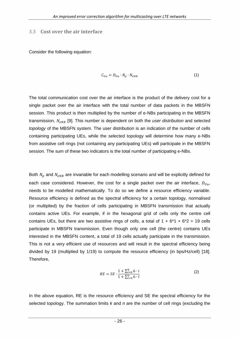
Cost over the air interface 3.3
Consider the following equation:
(1)
The total communication cost over the air interface is the product of the delivery cost for a
single packet over the air interface with the total number of data packets in the MBSFN
session. This product is then multiplied by the number of e-NBs participating in the MBSFN
transmission, [9]. This number is dependent on both the user distribution and selected
topology of the MBSFN system. The user distribution is an indication of the number of cells
containing participating UEs, while the selected topology will determine how many e-NBs
from assistive cell rings (not containing any participating UEs) will participate in the MBSFN
session. The sum of these two indicators is the total number of participating e-NBs.
Both and are invariable for each modelling scenario and will be explicitly defined for
each case considered. However, the cost for a single packet over the air interface, ,
needs to be modelled mathematically. To do so we define a resource efficiency variable.
Resource efficiency is defined as the spectral efficiency for a certain topology, normalised
(or multiplied) by the fraction of cells participating in MBSFN transmission that actually
contains active UEs. For example, if in the hexagonal grid of cells only the centre cell
contains UEs, but there are two assistive rings of cells, a total of 1 + 6*1 + 6*2 = 19 cells
participate in MBSFN transmission. Even though only one cell (the centre) contains UEs
interested in the MBSFN content, a total of 19 cells actually participate in the transmission.
This is not a very efficient use of resources and will result in the spectral efficiency being
divided by 19 (multiplied by 1/19) to compute the resource efficiency (in bps/Hz/cell) [18].
Therefore,
∑
∑
(2)
In the above equation, RE is the resource efficiency and SE the spectral efficiency for the
selected topology. The summation limits k and n are the number of cell rings (excluding the
An improved error correction algorithm for multicasting over LTE networks
- 27 -
centre cell) containing UEs and the total number of cell rings participating respectively. The k
and n-indices relate to each other in a different way for each considered topology.
For AII:
For AAI:
For AAA:
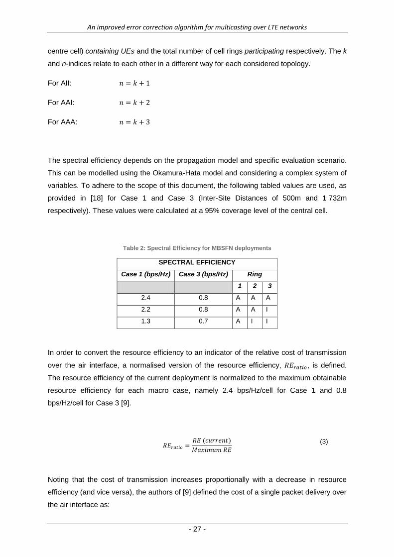
The spectral efficiency depends on the propagation model and specific evaluation scenario.
This can be modelled using the Okamura-Hata model and considering a complex system of
variables. To adhere to the scope of this document, the following tabled values are used, as
provided in [18] for Case 1 and Case 3 (Inter-Site Distances of 500m and 1 732m
respectively). These values were calculated at a 95% coverage level of the central cell.
Table 2: Spectral Efficiency for MBSFN deployments
SPECTRAL EFFICIENCY
Case 1 (bps/Hz) Case 3 (bps/Hz) Ring
1 2 3
2.4 0.8 A A A
2.2 0.8 A A I
1.3 0.7 A I I
In order to convert the resource efficiency to an indicator of the relative cost of transmission
over the air interface, a normalised version of the resource efficiency, , is defined.
The resource efficiency of the current deployment is normalized to the maximum obtainable
resource efficiency for each macro case, namely 2.4 bps/Hz/cell for Case 1 and 0.8
bps/Hz/cell for Case 3 [9].
(3)
Noting that the cost of transmission increases proportionally with a decrease in resource
efficiency (and vice versa), the authors of [9] defined the cost of a single packet delivery over
the air interface as:

An improved error correction algorithm for multicasting over LTE networks
- 28 -
(4)
The combination of the above equations with the original cost expression in Equation 1
results in a complete mathematical model for the cost of packet delivery over the air
interface in an MBSFN system.
To show how the spectral efficiency of each deployment is normalised by the factor of
participating cells actually containing UEs, the resource efficiency associated with each
deployment is graphed below as a function of the number of cell rings containing subscribed
UEs.
Figure 8: Resource efficiency of MBSFN deployments
It is clear that, for small topologies, AII has the highest resource efficiency. However, as the
topology grows to include more cell rings, AII becomes the least efficient deployment option.
This is because of the higher spectral efficiency in AAA and AAI. Since AAA has a larger
spectral efficiency than AAI, it will eventually have the highest resource efficiency if the

An improved error correction algorithm for multicasting over LTE networks
- 29 -
topology is sufficiently large. In fact, when the topology has grown to include an infinite
number of cell rings, the resource efficiency of each deployment approaches the spectral
efficiency of that deployment as presented in Table 2. To prove that, consider the following
infinite analysis based on Equation 2:
Equation 2 states that
∑
∑
which is mathematically equivalent to
∑
∑
(
)
(
)
We know from Section 3.3 that,
where is a constant. Therefore,
Now, if the network size approaches an infinite number of cell rings,
Therefore, in an infinite analysis, AAA has a resource efficiency of 2.4 bps/Hz/cell, AAI has a
resource efficiency of 2.2 bps/Hz/cell with AII at 1.3 bps/Hz/cell.
An improved error correction algorithm for multicasting over LTE networks
- 30 -
Error correction costs 3.4
ARQ costs 3.4.1
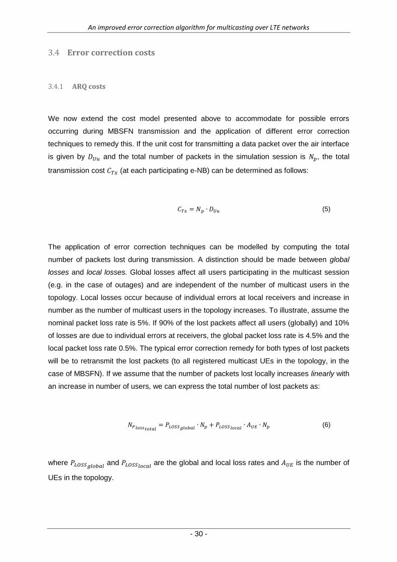
We now extend the cost model presented above to accommodate for possible errors
occurring during MBSFN transmission and the application of different error correction
techniques to remedy this. If the unit cost for transmitting a data packet over the air interface
is given by and the total number of packets in the simulation session is , the total
transmission cost (at each participating e-NB) can be determined as follows:
(5)
The application of error correction techniques can be modelled by computing the total
number of packets lost during transmission. A distinction should be made between global
losses and local losses. Global losses affect all users participating in the multicast session
(e.g. in the case of outages) and are independent of the number of multicast users in the
topology. Local losses occur because of individual errors at local receivers and increase in
number as the number of multicast users in the topology increases. To illustrate, assume the
nominal packet loss rate is 5%. If 90% of the lost packets affect all users (globally) and 10%
of losses are due to individual errors at receivers, the global packet loss rate is 4.5% and the
local packet loss rate 0.5%. The typical error correction remedy for both types of lost packets
will be to retransmit the lost packets (to all registered multicast UEs in the topology, in the
case of MBSFN). If we assume that the number of packets lost locally increases linearly with
an increase in number of users, we can express the total number of lost packets as:
(6)
where and
are the global and local loss rates and is the number of
UEs in the topology.

An improved error correction algorithm for multicasting over LTE networks
- 31 -
The total packet loss rate is:
(7)
These equations were validated by comparing simulation results to analyses published in [3],
[9] and showed good correlation. A detailed explanation appears in Chapter 5.
Now the total cost for ARQ transmission is the sum of the cost for the initial transmission and
the cost of the retransmitted packets [8]. However, since the retransmissions occur under
the same lossy conditions, a portion of the retransmitted packets might also be lost with
some probability greater than 0. These lost packets would also need to be retransmitted in
an iterative process (each iteration contributing to the total communication cost) and so forth
until the maximum number of retransmissions per packet is reached. According to 3GPP
specifications the maximum number of retransmissions per packet is 3, creating a ceiling of
maximum transmission cost [20]. It will be shown that for ARQ transmission, as the UEs
increase, the probability that each data packet needs to be retransmitted a maximum
number of times becomes large very quickly.
ARQ-FEC Combination costs 3.4.2
The 3GPP recommends using Raptor Codes as forward error correction technique in
MBSFN. The probability that a decoding failure may occur when a block of source code is
encoded as a Raptor code, is given by
{
(8)
where is the number of source symbols and is the number of encoded symbols [21]. It is
clear from the expression that, if the number of received encoded symbols is only slightly

An improved error correction algorithm for multicasting over LTE networks
- 32 -
more than the number of original source symbols, the probability of incorrectly decoding the
source block at each receiver decreases exponentially. If the number of encoded symbols is
equal to the number of source symbols, there is still an 85% chance that a decoding failure
will occur at the receiver side. The use of FEC therefore necessitates the introduction of an
overhead into the system to ensure correct decoding. In this simplified model it is assumed
that the FEC overhead is a constant, labelled as in equations. Therefore, if the FEC
overhead is 5%, , which is a typical simulation assumption ([3], [8]). If an MBSFN
transmission using FEC experiences some packet losses, the probability of a decoding
failure increases. It will then be necessary to retransmit certain packets when total packet
losses grow to such an extent that the effective FEC overhead falls below an acceptable
threshold, . This proposed technique therefore implements a combination of FEC and
retransmissions (ARQ). The total cost for this hybrid error correction technique is the sum of
the cost for the initial transmission (with overhead) and the cost of retransmissions [8]. In our
simplified model packets need to be retransmitted if the difference between the FEC
overhead and the total loss rate exceeds . The effective packet loss rate is:
{
(9)
Model variables 3.5
One clause in our hypothesis in Chapter 1 states that we can create a mathematical model
for “a specific MBSFN network under specific conditions”. This implies that we incorporated
a number of network variables which can be used to describe a specific MBSFN setup and a
different set of variables describing the conditions in which the MBSFN transmission takes
place. To show that our model does address this, we summarise some of the most important
variables in each category below.

An improved error correction algorithm for multicasting over LTE networks
- 33 -
Table 3: Model variables
Network Variables
Spectral efficiency
Topology
Inter-Site Distance
Number of participating cell rings
Number of cell rings containing UEs
Number of participating cells
Number of cells containing UEs
Condition Variables
User population
Nominal packet loss rate
Global packet loss rate
Local packet loss rate
Maximum retransmissions
Fixed FEC Overhead percentage
Minimum FEC threshold
Number of packets in the MBSFN transmission
Packet size
Two of the most important variables used to describe our network include the topology and
the macro Case. Combined, these two variables describe the implementation of the MBSFN
system in terms of the physical deployment of the cells (AAA, AAI, AII) and the Inter-Site
Distances between these cells. We also need to express the size of the network in terms of
the number of participating ( ) and UE-containing cell rings ( ). Depending on the type of
deployment, these values can be translated to the actual number of participating cells ( )
and the number of cells containing subscribed UEs ( ). This group of variables can be
combined to mathematically represent our simplified MBSFN system as described in Section
3.2. Depending on the values chosen for each variable, each simulated MBSFN system is
characterised by its specific spectral efficiency, which is used in cost calculations.
Once the network has been adequately modelled, we want to express the conditions under
which it operates for each simulation scenario. In an investigation into error correction
techniques, it is important to vary the packet loss rates experienced by the subscribed user
population. To model the behaviour of different error correction techniques, we have to
consider retransmissions for an ARQ-approach (specifically the maximum number of
retransmissions allowed per packet) and the overhead introduced if forward error correction

An improved error correction algorithm for multicasting over LTE networks
- 34 -
is used. Lastly, each simulation session will consist of a certain number of data packets of a
certain size. A combination of these variables is sufficient to create the many simulation
scenarios in our result set, which is the subject of the next chapter.
Conclusion 3.6
In this chapter, our model was explained at the hand of a series of equations and
accompanying discussions. Some assumptions with regards to the simulation parameters
and topology were clarified, followed by the mathematical definition of the transmission cost
over the air interface. This concept of “cost” was expanded to incorporate the cost of
different error correction techniques. We rounded off this chapter with a discussion of each
of the variables used to model both the network and the conditions under which it operates.
In summary, this chapter introduced the set of mathematical tools that was developed to
perform the tests in the next chapter.
An improved error correction algorithm for multicasting over LTE networks
- 35 -
4 Results
Chapter 4 – Results
Introduction 4.1
In this chapter we present the results of four tests, each differently designed to demonstrate
the functionality and versatility of our model. The first test considers the effect of a growing
user population on the cost of communication. This is followed by a test where the packet
loss rate is varied, providing results where the lowest-cost error correction scheme can be
selected given the loss conditions under which the simulation occurs. The third test can be
used to select the number of FEC redundant symbols that will result in the lowest
communication cost under given loss conditions, by expressing the cost as a function of the
fixed FEC overhead. The last test considers user distribution as an indication of the size of
the MBSFN topology and comments on the effect this variable has on the cost of
communication. Since this last variable, the user distribution, plays an important role in our
algorithm, it is added as a third dimension in all tests. We also publish results for both macro
Cases – Case 1 with an ISD of 500m and Case 3 with an ISD of 1 732m.
An improved error correction algorithm for multicasting over LTE networks
- 36 -
Test 1: User Population vs. MBSFN Cost 4.2
Test scope and purpose 4.2.1
This test investigates and quantifies the effect of a growing user population on a multicast
LTE environment. It only considers the cost associated with over-the-air transmission in an
MBSFN system and will study three different MBSFN deployments (AAA, AAI, AII). Three
different error correction paradigms will be applied to each deployment – ARQ, combination
ARQ-FEC (labelled HARQ) and FEC only. A third dimension, the size of the selected
topology (the number of participating e-NB cells), significantly affects the test results and is
discussed and measured as well. The model will provide a first-order answer to selecting the
lowest-cost combination of deployment and error correction scheme given a certain number
of subscribed multicast users.
Simulation setup 4.2.2
Two different test scenarios are set up. The first for an ISD of 500m (Case 1) and the second
for an ISD of 1 732m (Case 3). For both tests a total of 10 000 data packets are transmitted
in the simulation. Propagation characteristics are according to the Okamura-Hata model [18].
We also assume that the UEs have low mobility (average UE speed of only 3km/h). The e-
NB cells are arranged in a hexagonal grid, as discussed. To show the effect of the third
dimension (network size), the results of this test are presented for a small network and a
large network for each macro Case. The smaller network contains UEs in the centre cell and
the first two cell rings surrounding the centre (i.e. K = 2). This amounts to a total of 19 UE
drop locations. For the larger network, a total of 19 cell rings (plus the centre cell) contains
subscribed UEs – i.e. 1 141 cells. For this simulation the user population increases in
intervals of 25 from 1 subscribed user to a total of 400 multicast UEs.
The simulation occurs in a lossy environment, with a nominal packet loss rate of 5%. The
local loss rate is 10% of the nominal and the global loss rate is 90% of the nominal. Three
different error correction techniques are applied. The first is a simple application of ARQ.
Secondly, a combination of ARQ and FEC techniques are applied. Lastly, a theoretical
application of pure FEC is simulated. Overhead due to FEC is fixed at 5%. This is a typical
simulation assumption discussed in [3], [8] and [22].

An improved error correction algorithm for multicasting over LTE networks
- 37 -
Test results 4.2.3
Figure 9: User Population vs. MBSFN Cost - Case 1, k = 2. The bordered section is enlarged on the right to show more detail.

An improved error correction algorithm for multicasting over LTE networks
- 38 -
Figure 10: User Population vs. MBSFN Cost - Case 1, k = 19. The bordered section is enlarged on the right to show more detail.

An improved error correction algorithm for multicasting over LTE networks
- 39 -
Figure 11: User Population vs. MBSFN Cost – Case 3, k = 2. Figure 9 (Case 1, k = 2) is repeated on the right to aid visual comparison.

An improved error correction algorithm for multicasting over LTE networks
- 40 -
Figure 12: User Population vs. MBSFN Cost - Case 3, k = 19. The bordered section is enlarged on the right to show more detail.

An improved error correction algorithm for multicasting over LTE networks
- 41 -
Discussion 4.2.4
Consider the cost diagram for Case 1 (Figure 9). For each deployment considered, the cost
associated with ARQ transmissions quickly grows to a maximum with an increase in user
population. A larger number of users results in a higher probability of transmission failure,
increasing the number of required retransmissions. 3GPP specifications dictate that ARQ
cost is at a maximum if each data packet in the session is retransmitted three times, creating
the cost ceiling evident in the figure [20]. A hybrid combination of ARQ and FEC techniques
(labelled HARQ in the figure) will provide a better cost characteristic. A constant FEC
overhead of 5% is assumed. Even though FEC transmission introduces a high overhead into
the system, it is less affected by packet losses since each receiver can tolerate a number of
lost packets and still be able to decode all source packets correctly. This results in a lower
overall cost than ARQ for user populations less than 300 [22]. When the population rises to
above 300, the probability that each packet needs to be retransmitted a maximum number of
three times increases to near unity, resulting in a cost ceiling. For HARQ, the maximum cost
is slightly higher than for ARQ as it includes a small FEC overhead for each data packet.
The third approach is a purely theoretical approach and was proposed by [8]. It utilizes only
forward error correction. Since FEC is completely unaffected by individual errors at isolated
receivers, this approach can scale to any number of users without a rise in total cost. It can
be shown, however, that the required overhead might become unacceptably high for a high
number of users. This approach will also require a significant amount of feedback from each
subscribed user to ensure that each source block has been correctly decoded [22].
The results also illustrate the relationship between the different deployments considered
(AAA, AAI, AII). Figure 9 is a small network, with the number of cell rings containing
subscribed users (K) equal to two. For this smaller network the AAA-deployment has
proportionally the highest average cost for all three error correction paradigms, followed by
AAI and with AII the lowest-cost option. This is because of the inefficient use of resources
when a large number of cells assist in the MBSFN transmission, with only a small subset
actually containing subscribed users [9]. There are, however, multiple points of intersection
between the individual error correction curves for each deployment. For example, from the
enlarged section in the figure it is clear that for a simulation scenario of between 160 and
205 users, an ARQ-FEC combination in an AAI deployment would be a lower-cost solution
than an AII-deployment using ARQ as error correction. In the same way, pure FEC in an

An improved error correction algorithm for multicasting over LTE networks
- 42 -
AAA-deployment will be lower-cost than ARQ and HARQ in the proportionally lower-cost AAI
and AII deployments for user populations larger than 300.
Figure 10 presents a much more complex picture. The network size has grown to a total of
19 cell rings containing subscribed users (k = 19) with the costs associated with each
deployment having converged. AII-deployments are now proportionally the highest-cost
solutions, followed by AAA and AAI. However, for a population between 50 and 280 UEs, an
AAA-deployment with HARQ will be a lower-cost solution than AAI with ARQ. AII with HARQ
will provide a lower overall telecommunications cost than both AAA and AAI with ARQ, for a
population between 125 and 235. Several other points of intersection can be identified from
the figure, with all curves converging for small populations. To show the complex
interrelationship between the deployments for small populations, a section of the figure is
enlarged showing several points of intersection.
Now consider the same test done on a Case 3 network (Figures 11 & 12). Though the
results are similar to those for a Case 1 network, the different deployments compare
differently to each other, with AAA still most expensive for smaller networks. For a large
network (k = 19), the curves associated with each deployment has converged in a similar
manner to those for Case 1 networks. However, AAA remains the most expensive
deployment for this setup, followed by AAI and AII (in that order). For more on the effect of
network size on the total telecommunications cost for each deployment, see Section 4.5.
Validation 4.2.5
The results of this test are used to validate the simplified model for over-the-air MBSFN
transmission, by comparing it to a similar model. The mathematical model was validated by
comparing simulation results to analyses published in [3], [9] and showed good correlation.
Even though this new model uses some approximations and assumptions for a simpler,
faster model, it correlates well with published results. For a detailed discussion and the
computation of a correlation coefficient with literature, see Chapter 5 Section 5.3. All other
tests published in this document are new tests – either unpublished or significantly different
from published sources as far as our literature survey could determine.

An improved error correction algorithm for multicasting over LTE networks
- 43 -
Test 2: Packet Loss Rate vs. MBSFN Cost 4.3
Test Scope and Purpose 4.3.1
We next investigate the effect of a varying packet loss rate on the performance of the three
defined error correction paradigms. Once again this test is conducted using a simplified
MBSFN cost model for data transmission over the air interface of the LTE system. We seek
to quantify the relationship between the costs of these error correction approaches when
each is applied to three different MBSFN deployments (AAA, AAI, AII), if they are plotted
against an ever increasing nominal packet loss rate. A third dimension, the size of the
selected topology, will affect the results of the test significantly and is discussed and
measured as well. The model will provide a first order answer to selecting the lowest-cost
combination of deployment and error correction scheme given the packet loss rate of the air
interface.
Simulation Setup 4.3.2
The test is conducted for both of the macro Cases that our model was designed for. Macro
Case 1 corresponds to an ISD of 500m and Case 3 to an ISD of 1 732m. Note that, although
the macro Cases are presented in different result sets for the sake of simplicity, the model is
able to compare costs between deployments of each of the cases and will eventually be able
to suggest a lowest-cost case for a specific scenario, considering all parameters.
Propagation characteristics are similar to those used for Test 1. The simulation session
consists of 10 000 data packets in a hexagonal grid of e-NB cells with a fixed population of
100 subscribed users. To show the effect of the third dimension (network size), the results of
this test are presented for a small network and a large network for each macro Case. The
smaller network contains UEs in the centre cell and the first two cell rings surrounding the
centre. This amounts to a total of 19 UE drop locations. For the larger network, a total of 19
cell rings (plus the centre cell) contains subscribed UEs – i.e. 1 141 cells. We increase the
nominal packet loss rate in intervals of 1% to around 30% for each test. The local loss rate is
still 10% of the nominal loss rate, while the global loss rate is at 90% of the nominal. The
FEC overhead is variable to show its effect on costs – results are published for a 5% and a
15% FEC overhead for each Case and network size.

An improved error correction algorithm for multicasting over LTE networks
- 44 -
Test Results 4.3.3
Figure 13: Packet Loss Rate vs. MBSFN Cost – Case 1, k = 2, FEC = 5%
Figure 14: Packet Loss Rate vs. MBSFN Cost – Case 1, k = 2, FEC = 15%
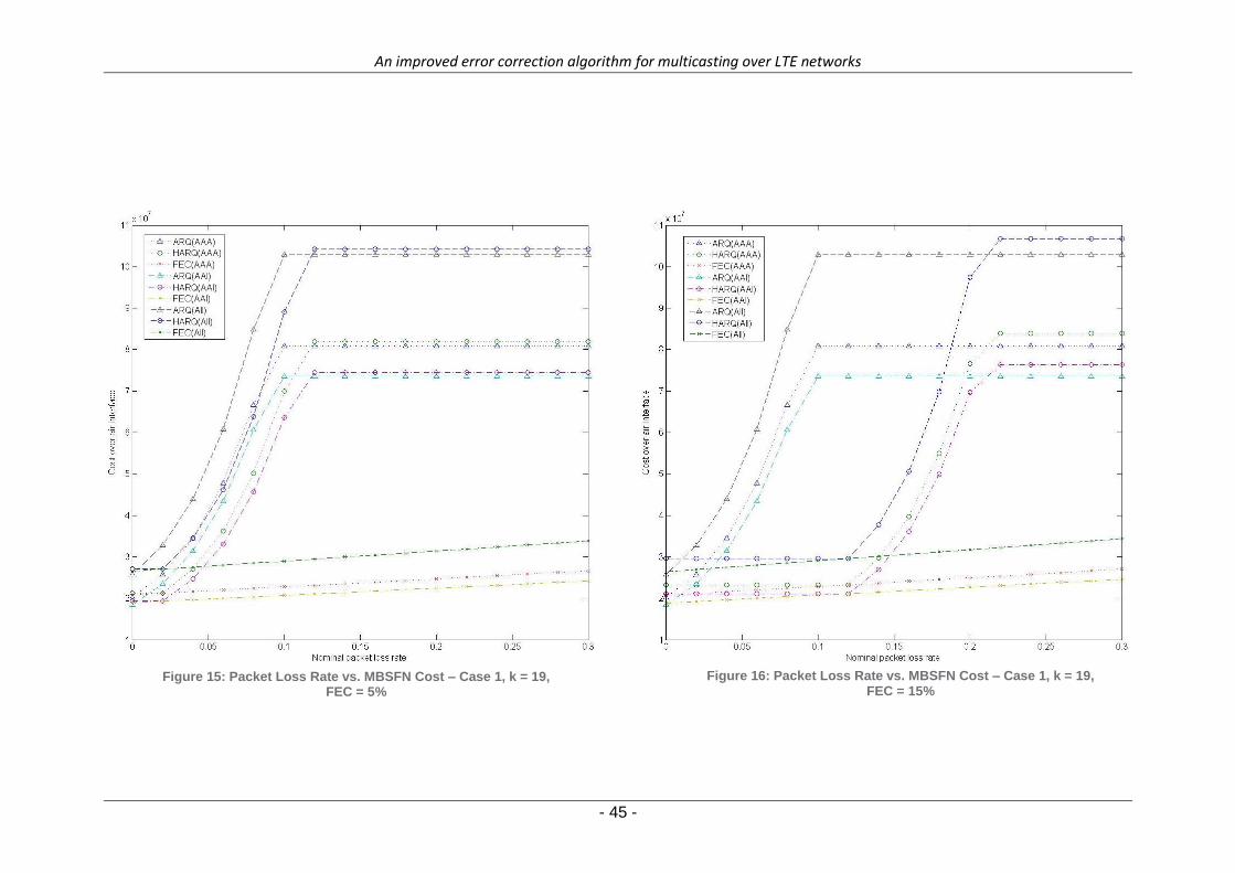
An improved error correction algorithm for multicasting over LTE networks
- 45 -
Figure 15: Packet Loss Rate vs. MBSFN Cost – Case 1, k = 19, FEC = 5%
Figure 16: Packet Loss Rate vs. MBSFN Cost – Case 1, k = 19, FEC = 15%

An improved error correction algorithm for multicasting over LTE networks
- 46 -
Figure 17: Packet Loss Rate vs. MBSFN Cost – Case 3, k = 2, FEC = 5% Figure 18: Packet Loss Rate vs. MBSFN Cost – Case 3, k = 19, FEC = 5%

An improved error correction algorithm for multicasting over LTE networks
- 47 -
Figure 19: Packet Loss Rate vs. MBSFN Cost – Case 3, k = 2, FEC = 15% Figure 20: Packet Loss Rate vs. MBSFN Cost – Case 3, k = 19, FEC = 15%

An improved error correction algorithm for multicasting over LTE networks
- 48 -
Discussion 4.3.4
From Figure 13 it is clear that ARQ costs increase quickly with an increase in the packet loss
rate – a higher number of transmission errors necessitates a higher number of
retransmissions. Note that FEC overhead is fixed at 5% in this figure. This results in the
HARQ costs for all three deployments remaining constant, or closely following the ideal
curve for pure FEC, for nominal packet loss rates of under 3%. This is because the fixed
amount of FEC overhead included in the data provides enough redundancy to decode the
source message, even with some losses in the transmission. As soon as the packet loss rate
increases to above 3%, the HARQ costs for each deployment increases at the same rate of
change as that of the ARQ costs for the same deployment (the parallel lines in the figure).
Both ARQ and HARQ (for each deployment) reach a maximum cost at a nominal packet loss
rate of around 10%. The maximum value conditions are the same as those for the previous
test (Section 4.2) with a maximum number of allowed retransmissions of three [16]. The pure
FEC approach increases incrementally with a rise in packet loss rate, since more packet
errors would require a greater amount of FEC overhead to decode the MBSFN transmission
with an acceptably low failure probability (see Luby’s probability for decoding failure of
Raptor codes in Section 3.4.2 and [7], [23]).
Comparing Figure 14 with Figure 13, the effect of FEC overhead becomes clear. Figure 14
presents the same macro Case and network size than that of Figure 13, but with a fixed FEC
overhead of 15% as opposed to 5%. The HARQ costs remain constant for longer for each
deployment, as the large amount of FEC overhead is enough to decode the source message
even with a considerable amount of transmission errors. Also, the larger overhead added to
each retransmitted packet results in a larger maximum cost for HARQ costs at the maximum
allowed three retransmissions per packet.
Several quantitative conclusions can also be drawn from the side-by-side comparison of
Figures 13 and 14. Since packet retransmissions quickly increase the cost of communication
(the sections of the ARQ and HARQ curves with the steepest slope), it should be avoided.
The minimum inflection point of each of the HARQ-curves in Figure 13 indicates that, with a
fixed FEC overhead of 5%, packet losses of up to 3% can be tolerated before
retransmissions are required. However, the same inflection points in Figure 14 occur only at
a much higher packet loss rate of 12%. This reveals that the higher FEC overhead of 15%
will allow for the maximum allowable packet loss rate to be pushed up to at least 12% before
retransmissions are required. Another important deduction can be made from the maximum
An improved error correction algorithm for multicasting over LTE networks
- 49 -
inflection points of each of the curves. Once the maximum allowable number of
retransmissions is reached, extra retransmission requests for the same data packet from
subscribers will be ignored and they might be unable to fully decode the source message.
Therefore the maximum inflection points indicate the maximum packet loss rate at which that
error correction technique can reliably be used, while still allowing for all subscribers to
correct all transmission errors. Figures 13 and 14 indicate that ARQ can only be used as
error correction technique in MBSFN systems where the packet loss rate is less than 10%.
Our model predicts that for a packet loss rate higher than this, transmission errors could be
unavoidable. HARQ can be reliably used as error correction technique under conditions
where the loss rate is up to 12% (assuming a FEC overhead of 5%) and up to 22% if the
amount of fixed FEC overhead is 15%.
In Figure 15 the network is larger (k = 19), changing the relationship between different
deployments. Specifically, AII is now proportionally the most expensive deployment, with AAI
the least expensive solution. This is because of the much higher spectral efficiency of AAA
and AAI when compared to AII, as discussed in Section 3.3 [18]. The relationship between
individual curves are however more complex than that, with many points of intersection
evident in the figure. Figure 16 presents the same scenario as Figure 15, but with a much
larger fixed FEC overhead. The comparison of Figure 16 with Figure 15 is analogous to the
discussion above comparing Figures 13 and 14.
Figures 17 to 20 repeat the tests in Figures 13 to 16, but for macro Case 3 (ISD of 1 732m).
The results are much the same as those already discussed, but note that the three
deployments considered overlap less for smaller networks. The side-by-side comparison of
Figures 17 and 18 illustrates the effect of network size on the communication cost. Note that
for the smaller network (k = 2) in Figure 17, the total cost for each deployment option is
considerably lower (in the order of 106) than that for the larger network in Figure 18 (with
costs in the order of 107). It is clear that for a larger network, there are many more points of
intersection between the individual error correction cost curves of each deployment,
indicating that the decision for a lowest-cost error correction scheme becomes more
complex as the network grows in size. This is because the subscribed users are more
distributed in a larger network. The effect of network size on communication costs is
thoroughly examined in Section 4.5.

An improved error correction algorithm for multicasting over LTE networks
- 50 -
Test 3: FEC Overhead vs. MBSFN Cost 4.4
Test Scope and Purpose 4.4.1
We now vary the amount of fixed FEC overhead in our second error correction approach –
using a combination of ARQ and FEC – in order to demonstrate our model’s ability to
determine the optimal FEC overhead for a specific MBSFN setup. Costs are compared
between three MBSFN deployments (AAA, AAI, AII) and each error correction paradigm.
Two more dimensions are considered and their effects demonstrated: the packet loss rate
will influence the point of optimal FEC overhead; the size of the selected topology greatly
influences the relationship between the three different MBSFN deployments.
Simulation Setup 4.4.2
For this test we assume a macro Case 1 network with an ISD of 500m. For all tests a total of
10 000 data packets are transmitted in the simulation. We also assume a fixed population of
100 subscribed users. Propagation characteristics are similar to the previous tests (Sections
4.2 – 4.3). We illustrate the effect of network size on the total communications cost by
publishing results for a small network (k = 2) and for a large network (k = 19). Another
important dimension for this test is the effect of the nominal packet loss rate on the optimal
point of FEC overhead for a combination ARQ-FEC setup. The packet loss rate was
investigated in detail in a previous test (Section 4.3), so for this test we only publish results
for loss rates of 5% and 10% for each simulation setup. The fixed FEC overhead in the
combination ARQ-FEC error correction approach (labelled “HARQ” in all figures) are
increased from 1% to 15% in intervals of 1%. The local loss rate is still 10% of the nominal
loss rate, while the global loss rate is at 90% of the nominal. As per 3GPP specifications ,
the maximum number of retransmissions in the ARQ and HARQ schemes is three [16].

An improved error correction algorithm for multicasting over LTE networks
- 51 -
Test Results 4.4.3
Figure 21: FEC Overhead vs. MBSFN Cost – Case 1, k = 2, Packet loss rate = 5%

An improved error correction algorithm for multicasting over LTE networks
- 52 -
Figure 22: FEC Overhead vs. MBSFN Cost – Case 1, k = 2, Packet loss rate = 10%

An improved error correction algorithm for multicasting over LTE networks
- 53 -
Figure 23: FEC Overhead vs. MBSFN Cost – Case 1, k = 19, Packet loss rate = 5%
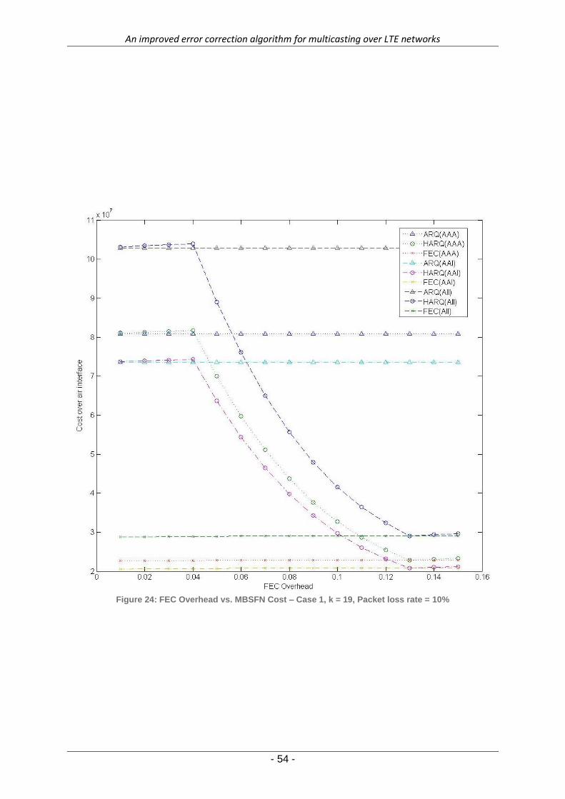
An improved error correction algorithm for multicasting over LTE networks
- 54 -
Figure 24: FEC Overhead vs. MBSFN Cost – Case 1, k = 19, Packet loss rate = 10%

An improved error correction algorithm for multicasting over LTE networks
- 55 -
Discussion 4.4.4
Figures 21 to 24 present the total telecommunications cost as a function of the fixed FEC
overhead in HARQ in a number of different scenarios. Since the ARQ and pure FEC
approaches do not contain any fixed FEC overhead they are independent of this variable
and their respective cost values remain constant. Both values are included in this figure,
however, to show the points of intersection between the curves. The amount of fixed
overhead does impact the telecommunications cost of the combination ARQ-FEC approach
significantly. For each deployment the lowest cost point on the HARQ curve, intersecting
with the constant pure FEC cost value, is the optimal fixed FEC overhead point for that
system. In Figure 21, with a packet loss rate of 5%, that optimal point is shown to be a fixed
FEC overhead of 8% for all three deployments considered. For lower FEC overhead
conditions (1% to 7%) the cost is high because of the large number of retransmissions
required to successfully recover the source message from a lossy transmission. In these
cases the prefixed FEC overhead does not provide enough redundancy to counter the
packet losses and there is a high probability that the source message will not be successfully
decoded (see Equation 8 in Chapter 3). For FEC overhead values larger than 8%, the total
cost increases without having any effect on the system’s performance [8]. This is because
the fixed FEC overhead will already provide enough redundancy to successfully decode the
source message at 8% and any extra overhead is unnecessary. Note that the HARQ and
pure FEC curves intersect at the 8% point, indicating that at this point the fixed FEC
overhead is exactly enough to decode the source message successfully for this packet loss
rate without requesting any retransmissions from the source. Determining this point can be
difficult in the real world though, since it requires accurate knowledge of the loss
characteristics of the utilized communication channel. Nevertheless, it provides a sufficiently
low communication cost, close to the ideal, to be a main point of investigation in this study.
Amongst other things, it will indicate to operators the type and number of Raptor Code
symbols to be used in the transmission.
In Figure 22 the loss rate has increased to 10%. Since more packets are lost during
transmission, a higher FEC overhead is required to successfully decode the source
message. In this case the optimal fixed FEC overhead is around 13%. For this high packet
loss rate, there is a slight increase in the HARQ costs for FEC overhead values of 1% to 4%.
This is because the added FEC overhead is not enough to avert any retransmissions, but
does require the transmission of redundant data. We can conclude from this that, under
conditions where the packet loss rate is up to 10%, it is inefficient to add FEC overhead of
less than 4%. At 4% the HARQ curves for each deployment forms a local maximum

An improved error correction algorithm for multicasting over LTE networks
- 56 -
inflection point and rapidly falls to the minimum inflection point as the number of required
retransmissions decreases. Figures 23 and 24 repeats these two tests, but for a large
network (k = 19). Results are similar to Figures 21 and 22 for each individual deployment,
but the relationship between different deployments has changed, with AII now the most
expensive solution and AAI the least expensive. For a detailed discussion on the effect of
network size on costs, see Section 4.5.

An improved error correction algorithm for multicasting over LTE networks
- 57 -
Test 4: User Distribution vs. MBSFN Cost 4.5
Test scope and purpose 4.5.1
With this test we illustrate the effect and complex nature of the all-important “third dimension”
in previous tests, namely the network size. The total telecommunications cost in the MBSFN
system is depicted as a function of the number of hexagonal cell rings actually containing
UEs subscribed to the multicast transmission. Since the number of UEs is a constant for
each scenario, a larger network implies a wider distribution of UEs, whereas a smaller
network, containing the same amount of UEs, implies a dense user distribution. For this
reason, the test can be regarded as a user distribution test. We compare the costs of the
three MBSFN deployments (AAA, AAI, AII) with the error correction paradigms applied to
each. The telecommunications cost and the relationship between the MBSFN deployments
are further dependent on the amount of fixed FEC overhead in the HARQ-approach and the
packet loss rate. We consider both variables in our test. This test provides a first order
answer to selecting the lowest-cost MBSFN deployment combined with an error correction
scheme, given a user distribution.
Simulation Setup 4.5.2
The test is completed for two macro Cases – macro Case 1 with an ISD of 500m and macro
Case 3 with an ISD of 1 732m. Similar to previous tests, a total of 10 000 data packets are
transmitted in the simulation, with a fixed user population of a 100 subscribed users.
Propagation characteristics are the same as in previous tests (Sections 4.2 – 4.4). The main
independent variable in this test is the network size. The size is expressed as the number of
hexagonal cell rings containing UEs subscribed to the MBSFN transmission (the variable k in
previous tests). The size is increased from 0 cell rings (UEs are all contained in the centre
cell) to a large network of 20 cell rings. We publish results for a packet loss rate of 5% and
25%. The fixed FEC overhead in the combination ARQ-FEC error correction approach
(labelled “HARQ” in all figures) are increased from 5% to 15% in two separate scenarios.
The local loss rate is still 10% of the nominal loss rate, while the global loss rate is at 90% of
the nominal.

An improved error correction algorithm for multicasting over LTE networks
- 58 -
Test Results 4.5.3
Figure 25: User Distribution vs. MBSFN Cost – Case 1, Packet loss rate = 5%, FEC Overhead = 5%

An improved error correction algorithm for multicasting over LTE networks
- 59 -
Figure 26: User Distribution vs. MBSFN Cost – Case 1, Packet loss rate = 25%, FEC Overhead = 5%. Figure 25 (Packet loss rate = 5%, FEC Overhead = 5%) is repeated on the right to aid visual comparison.

An improved error correction algorithm for multicasting over LTE networks
- 60 -
Figure 27: User Distribution vs. MBSFN Cost – Case 1, Packet loss rate = 5%, FEC Overhead = 15%. Figure 25 (Packet loss rate = 5%, FEC Overhead = 5%) is repeated on the right to aid visual comparison.

An improved error correction algorithm for multicasting over LTE networks
- 61 -
Figure 28: User Distribution vs. MBSFN Cost – Case 3, Packet loss rate = 5%, FEC Overhead = 5%. Figure 25 (Case 1) is repeated on the right to aid visual comparison.

An improved error correction algorithm for multicasting over LTE networks
- 62 -
Discussion 4.5.4
Consider Figure 25 with a nominal packet loss rate of 5% and a fixed FEC overhead of 5%.
The complex comparison between MBSFN deployments of different sizes is evident in this
figure. It is clear that for small topologies, the AII deployment provides the lowest overall
cost. At this loss rate and overhead percentage (5% each) we can conclude from our
previous results that for each deployment (AAA, AAI, AII) the ARQ-curve will always be the
most expensive option for that deployment at all network sizes, followed by HARQ and then
the pure FEC approach. Therefore, the ARQ(AII)-curve is always above the HARQ(AII)
curve in Figure 25, followed by the FEC(AII)-curve tracing the theoretical minimum for an AII-
deployment against a growing network size. The same is also true of AAA and AAI-
deployments. However, as was shown in previous tests, the network size does determine
which of the three deployment options provides the lowest overall cost (average of all three
error correction approaches for that deployment), so we can expect some points of
intersection between the individual cost curves if the network size is varied. In fact, when the
number of cell rings containing UEs is 0 (i.e. all users are located in the centre cell), the cost
for all three error correction approaches in an AII-deployment is significantly lower than
those for AAA and AAI. The high initial costs for the AAA and AAI deployments are a result
of the low resource efficiency when the number of cell rings containing UEs is low. The AII-
deployment has, however, a lower spectral efficiency than AAA and AAI, resulting in the total
cost quickly rising as the topology grows to include more cell rings. At a network size of just
two rings, the ARQ(AII)-curve already intersects the FEC(AAI)-curve, becoming a more
expensive option for networks larger than two rings. It is quickly followed by the HARQ(AII)-
curve, crossing the FEC(AAI) curve at a network size of three. The cost curves for AII
continue to cross the AAA and AAI-curves, gradually becoming the more expensive option at
each point of intersection. For large topologies (number of participating cell rings more than
12), AII is the most expensive deployment option (average cost for the three error correction
paradigms), followed by AAA and AAI. From our infinity analysis in Section 3.3 we can
conclude that AAA will eventually become the cheapest deployment option if the network
continues to grow.
In Figure 26 the packet loss rate is increased to an artificially high 25%, to illustrate the effect
that this variable has in the third dimension. The packet loss rate has already been
investigated in Test 2 (Section 4.3) and this figure serves to clarify the role that network size
plays in determining the communication cost if the packet loss rate is varied. A side-by-side
comparison with Figure 25, allows for the higher packet loss rate (25%) to be compared to

An improved error correction algorithm for multicasting over LTE networks
- 63 -
the lower loss rate of 5%. Note that the cost scale in Figure 26 is double that of Figure 25. A
higher loss rate implies a larger number of retransmissions, increasing the total
telecommunications cost for the ARQ and HARQ error correction schemes considerably.
Since both of these error correction paradigms approach the maximum number of
retransmissions at this high loss rate, the individual ARQ and HARQ curves converge for
each MBSFN deployment, as can be seen from the side-by-side comparison with Figure 25
Comparing Figure 27 with Figure 25, shows the effect of the fixed FEC overhead on the
telecommunications cost. Refer back to Test 3 (Section 4.4) for a detailed look at the amount
of FEC overhead added if a combination of ARQ and FEC is used as error correction
technique. Since the ARQ approach contains no FEC overhead and the pure FEC approach
utilises a variable FEC overhead, it is only the HARQ costs that are affected by this variable.
More specifically, a higher amount of fixed FEC overhead results in a lower overall HARQ
cost as the network grows. This is because the fixed amount of FEC overhead is enough to
decode the source message at all network terminals without requiring extra packet
retransmissions when losses occur. The side-by-side comparison reveals that the order of
the curves changes at large network sizes. At a size of 20 cell rings, the HARQ(AII)-curve is
more expensive than the ARQ(AAI)-curve and almost just as expensive as the ARQ(AAA)-
option if the FEC-overhead is 5% (Figure 25). In Figure 27 the FEC-overhead is increased to
15% and HARQ(AII) is now less expensive than both ARQ(AAA) and ARQ(AAI), since no
retransmissions are required.
Finally, Figure 28 illustrates the difference between Case 1 and Case 3 networks. The same
simulation parameters is used in both figures, but the Inter-Site Distance is increased from
500m to 1 732m. Since the difference in spectral efficiency between different Case 3
deployments is much lower than that for Case 1 networks (see Table 2 in Section 3.3), there
is much less overlap between individual curves in Figure 28 (on the left) than Figure 25 (on
the right) when the network grows. For the same reason, the cost increases at a lower rate
of change in Figure 28 as the network grows, resulting in lower overall transmission costs at
a large network size of 20 rings when compared to Figure 25.
An improved error correction algorithm for multicasting over LTE networks
- 64 -
5 Verification and Validation
Chapter 5 – Verification and Validation
Introduction 5.1
In this chapter we will verify and validate our mathematical model and results. In the
verification phase, we aim to prove that our model is mathematically accurate and performs
correctly. This is done by setting up a small simulation scenario and computing two result
sets – one by using our computerised model and the other by hand. We then compare the
results to show that results obtained using the computerised model are plausible, as the
same can also be obtained using step-by-step computations by hand.
The model is validated by setting up a simulation scenario according to the same
specifications as a published author and comparing the results. Since we have developed a
new improved model it would be impossible to copy a published simulation scenario in an
exact manner, so we simply compare our model to a similar model in literature. Several
similar aspects of both models are highlighted, confirming the validity of our model. We
prove that there is indeed a strong correlation between our model and credible, real world
results by computing the Pearson correlation coefficient between our result set and the
published results.
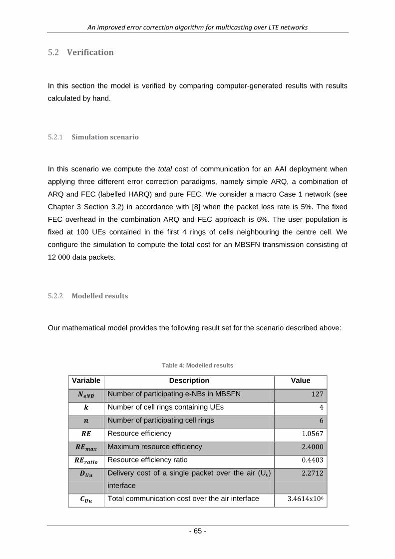
An improved error correction algorithm for multicasting over LTE networks
- 65 -
Verification 5.2
In this section the model is verified by comparing computer-generated results with results
calculated by hand.
Simulation scenario 5.2.1
In this scenario we compute the total cost of communication for an AAI deployment when
applying three different error correction paradigms, namely simple ARQ, a combination of
ARQ and FEC (labelled HARQ) and pure FEC. We consider a macro Case 1 network (see
Chapter 3 Section 3.2) in accordance with [8] when the packet loss rate is 5%. The fixed
FEC overhead in the combination ARQ and FEC approach is 6%. The user population is
fixed at 100 UEs contained in the first 4 rings of cells neighbouring the centre cell. We
configure the simulation to compute the total cost for an MBSFN transmission consisting of
12 000 data packets.
Modelled results 5.2.2
Our mathematical model provides the following result set for the scenario described above:
Table 4: Modelled results
Variable Description Value
Number of participating e-NBs in MBSFN 127
Number of cell rings containing UEs 4
Number of participating cell rings 6
Resource efficiency 1.0567
Maximum resource efficiency 2.4000
Resource efficiency ratio 0.4403
Delivery cost of a single packet over the air (Uu)
interface
2.2712
Total communication cost over the air interface 3.4614x10⁶

An improved error correction algorithm for multicasting over LTE networks
- 66 -
Variable Description Value
Communication cost with ARQ applied 6.9362x10⁶
Communication cost with a combination of ARQ
and FEC applied
4.6813x10⁶
Communication cost with pure FEC applied 3.7351x10⁶
Calculated results 5.2.3
See Chapter 3 for a definition of the symbols used in this chapter and the theoretical
background to our calculations.
Since the number of cell rings containing subscribed UEs (k) is 4, we know from the
discussion in Chapter 3 that,
The total number of cells participating in the transmission, , is:
∑
Consider the spectral efficiency values below:
Table 5: Spectral Efficiency for MBSFN deployments
SPECTRAL EFFICIENCY
Case 1 (bps/Hz) Case 3 (bps/Hz) Ring
1 2 3
2.4 0.8 A A A
2.2 0.8 A A I
1.3 0.7 A I I

An improved error correction algorithm for multicasting over LTE networks
- 67 -
For a Case 1 network and an AAI deployment, the spectral efficiency is 2.2 bps/Hz. From
Equation 2 in Chapter 3, we can compute the resource efficiency as:
∑
∑
∑
∑
The theoretical maximum resource efficiency for a Case 1 network is 2.4 bps/Hz/cell. This
indicates that:
We use the inverse of the resource efficiency to define a cost value for the transmission (as
discussed in Chapter 3).
Using this value, and noting that the total number of packets in the transmissions, , is
12 000, we can compute the total transmission cost (before error correction), as:
Since we know that

An improved error correction algorithm for multicasting over LTE networks
- 68 -
From Equation 7,
5.2.3.1 ARQ cost
If the initial number of retransmissions required is ,
The cost associated with these retransmissions, , is
We can assume that, under the same lossy conditions, the retransmitted packets would also
experience an equivalent amount of losses. We will then require a total of
Corresponding to a cost of
Keeping in mind that the maximum allowable number of retransmissions is 3 (according to
3GPP specifications [20], we can compute, in a similar manner, that

An improved error correction algorithm for multicasting over LTE networks
- 69 -
The total cost of the communication, including retransmission costs, is:
5.2.3.2 HARQ cost
The cost for an approach using a combination of FEC and ARQ can be computed in a
similar manner. We assume that the fixed amount of FEC overhead is .
According to the discussion in Chapter 3, the probability that a decoding failure could occur
increases as the number of packet losses increases. That is, the added overhead might not
provide enough redundancy to detect and correct possible errors in the transmission and
some retransmissions will be required. The total cost of this error correction approach is the
sum of the FEC overhead cost and the cost of possible retransmissions.
From Chapter 3 we get that:
{
(10)
To simplify this scenario, we’ll assume that is constant at 3%. (This value is based on
results published in [8] and our own similar conclusion in Chapter 4, Section 4.3).
Since,
we know that
and from our previous discussion
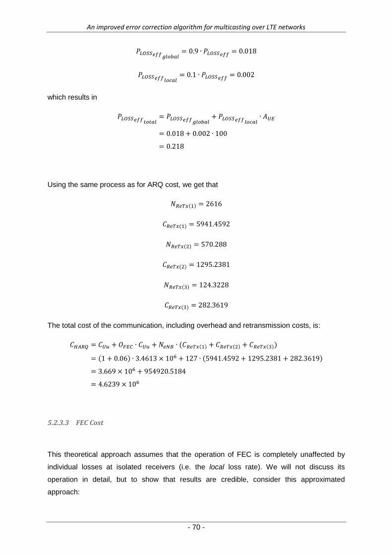
An improved error correction algorithm for multicasting over LTE networks
- 70 -
which results in
Using the same process as for ARQ cost, we get that
The total cost of the communication, including overhead and retransmission costs, is:
5.2.3.3 FEC Cost
This theoretical approach assumes that the operation of FEC is completely unaffected by
individual losses at isolated receivers (i.e. the local loss rate). We will not discuss its
operation in detail, but to show that results are credible, consider this approximated
approach:
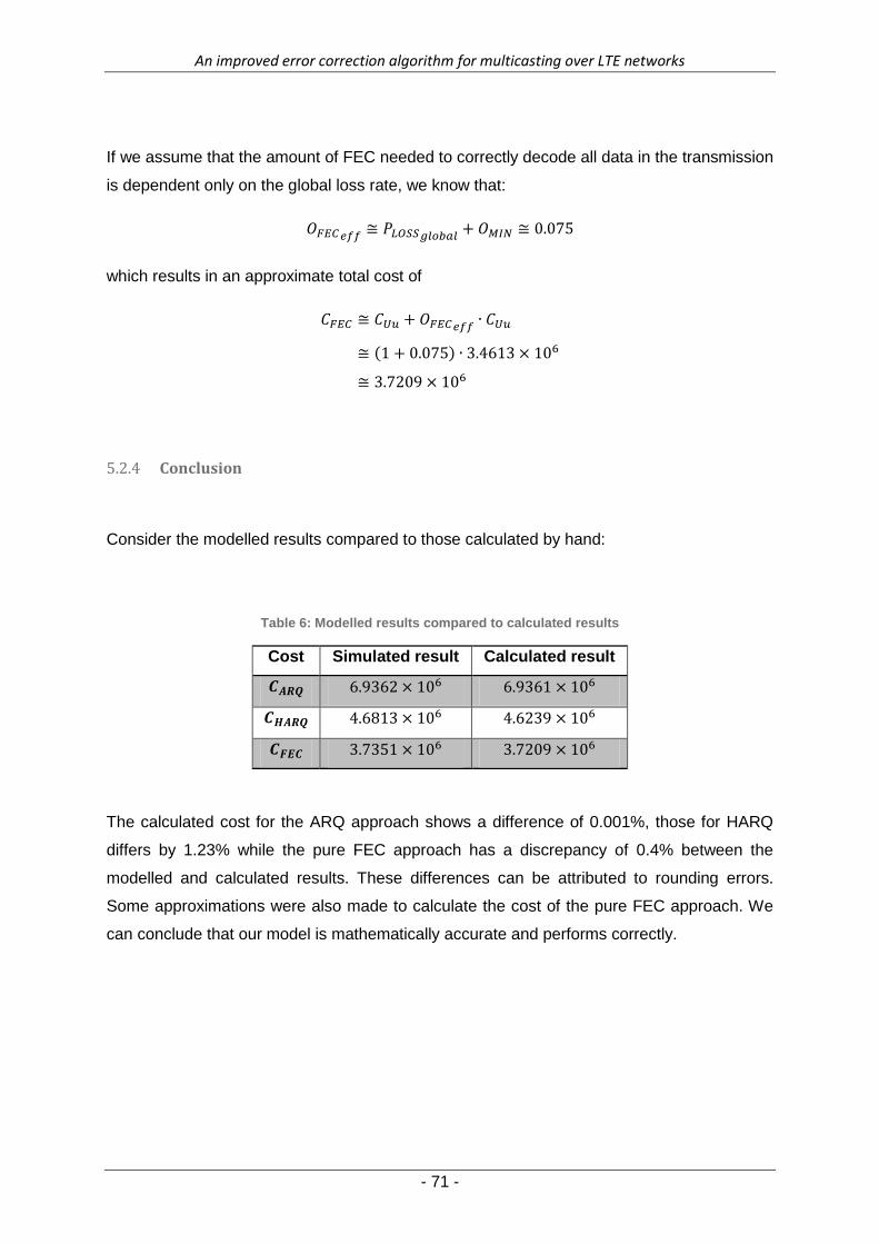
An improved error correction algorithm for multicasting over LTE networks
- 71 -
If we assume that the amount of FEC needed to correctly decode all data in the transmission
is dependent only on the global loss rate, we know that:
which results in an approximate total cost of
Conclusion 5.2.4
Consider the modelled results compared to those calculated by hand:
Table 6: Modelled results compared to calculated results
Cost Simulated result Calculated result
The calculated cost for the ARQ approach shows a difference of 0.001%, those for HARQ
differs by 1.23% while the pure FEC approach has a discrepancy of 0.4% between the
modelled and calculated results. These differences can be attributed to rounding errors.
Some approximations were also made to calculate the cost of the pure FEC approach. We
can conclude that our model is mathematically accurate and performs correctly.
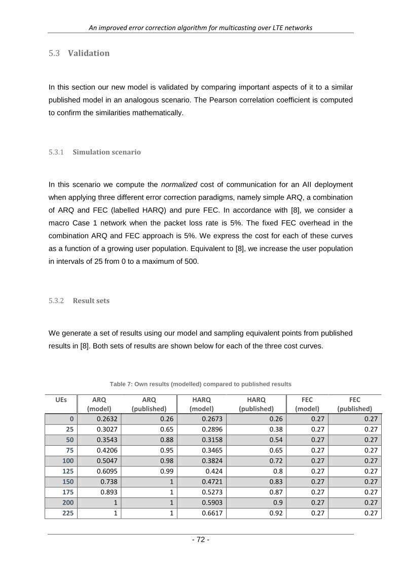
An improved error correction algorithm for multicasting over LTE networks
- 72 -
Validation 5.3
In this section our new model is validated by comparing important aspects of it to a similar
published model in an analogous scenario. The Pearson correlation coefficient is computed
to confirm the similarities mathematically.
Simulation scenario 5.3.1
In this scenario we compute the normalized cost of communication for an AII deployment
when applying three different error correction paradigms, namely simple ARQ, a combination
of ARQ and FEC (labelled HARQ) and pure FEC. In accordance with [8], we consider a
macro Case 1 network when the packet loss rate is 5%. The fixed FEC overhead in the
combination ARQ and FEC approach is 5%. We express the cost for each of these curves
as a function of a growing user population. Equivalent to [8], we increase the user population
in intervals of 25 from 0 to a maximum of 500.
Result sets 5.3.2
We generate a set of results using our model and sampling equivalent points from published
results in [8]. Both sets of results are shown below for each of the three cost curves.
Table 7: Own results (modelled) compared to published results
UEs ARQ (model)
ARQ (published)
HARQ (model)
HARQ (published)
FEC (model)
FEC (published)
0 0.2632 0.26 0.2673 0.26 0.27 0.27
25 0.3027 0.65 0.2896 0.38 0.27 0.27
50 0.3543 0.88 0.3158 0.54 0.27 0.27
75 0.4206 0.95 0.3465 0.65 0.27 0.27
100 0.5047 0.98 0.3824 0.72 0.27 0.27
125 0.6095 0.99 0.424 0.8 0.27 0.27
150 0.738 1 0.4721 0.83 0.27 0.27
175 0.893 1 0.5273 0.87 0.27 0.27
200 1 1 0.5903 0.9 0.27 0.27
225 1 1 0.6617 0.92 0.27 0.27
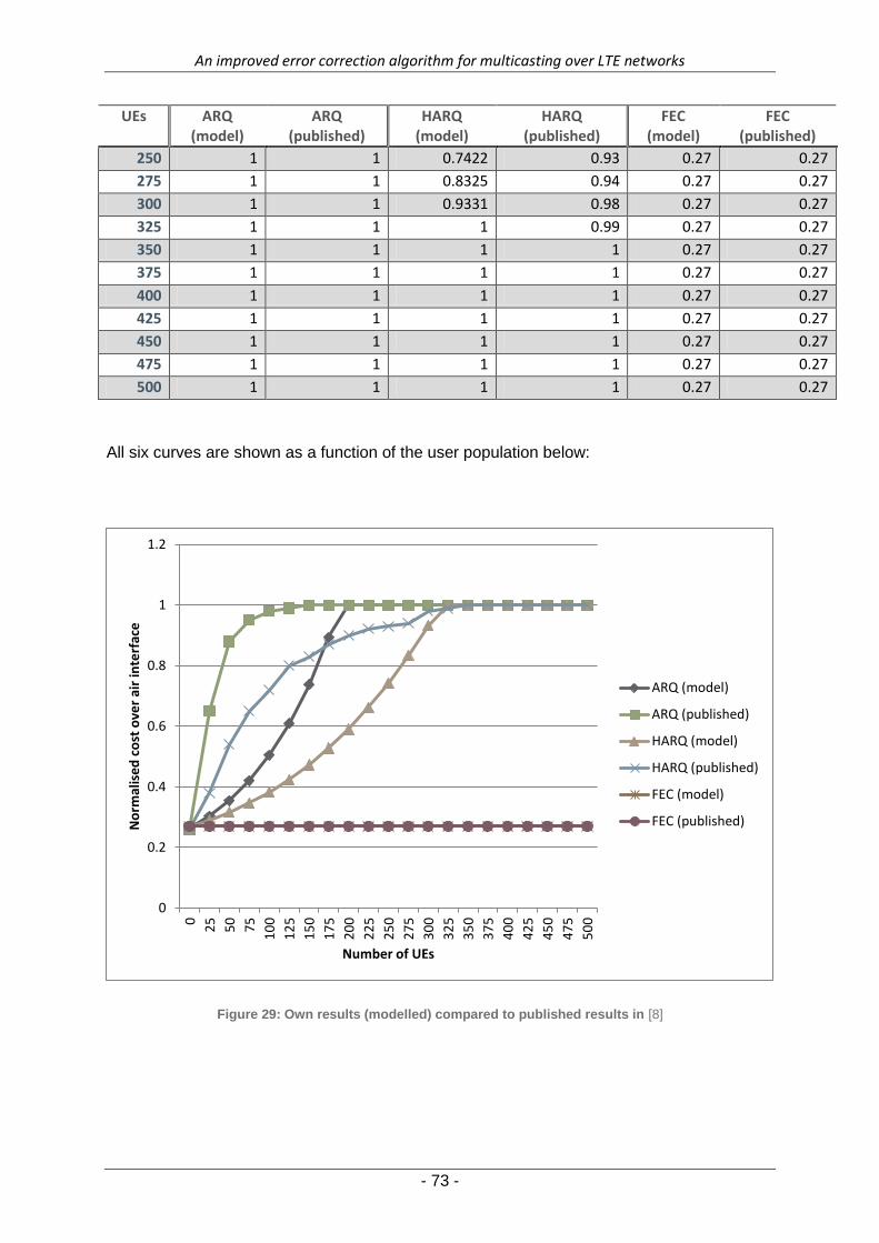
An improved error correction algorithm for multicasting over LTE networks
- 73 -
UEs ARQ (model)
ARQ (published)
HARQ (model)
HARQ (published)
FEC (model)
FEC (published)
250 1 1 0.7422 0.93 0.27 0.27
275 1 1 0.8325 0.94 0.27 0.27
300 1 1 0.9331 0.98 0.27 0.27
325 1 1 1 0.99 0.27 0.27
350 1 1 1 1 0.27 0.27
375 1 1 1 1 0.27 0.27
400 1 1 1 1 0.27 0.27
425 1 1 1 1 0.27 0.27
450 1 1 1 1 0.27 0.27
475 1 1 1 1 0.27 0.27
500 1 1 1 1 0.27 0.27
All six curves are shown as a function of the user population below:
Figure 29: Own results (modelled) compared to published results in [8]
0
0.2
0.4
0.6
0.8
1
1.2
0
25
50
75
10
0
12
5
15
0
17
5
20
0
22
5
25
0
27
5
30
0
32
5
35
0
37
5
40
0
42
5
45
0
47
5
50
0
No
rmal
ise
d c
ost
ove
r ai
r in
terf
ace
Number of UEs
ARQ (model)
ARQ (published)
HARQ (model)
HARQ (published)
FEC (model)
FEC (published)
An improved error correction algorithm for multicasting over LTE networks
- 74 -
Qualitative comparison 5.3.3
Consider Figure 29 showing the error correction cost curves for both our mathematical
model and similar results published in [8]. Since we have developed a new model we do not
aim to copy the published results, but simply compare certain aspects of it to a similar
model. It will in any case be impossible to copy the simulation scenario in an exact manner,
since the implementation details described in [8] are incomplete (such as loss conditions,
error distribution, maximum value conditions etc.). The scenario applied to our new
mathematical model was built from first principles in specification documents [16]. The vague
application of environmental and network variables in [8] explains most of the visible
discrepancies between results. Though specified maximum value conditions result in similar
cost ceilings for the modelled and published result sets, the published results generally show
higher costs for small user populations. The published results are the sum of transmission
costs over the air interface and the core network, which have a compounding effect if the
number of attached UEs is low, explaining this difference. Our new model only considers the
air interface, as explained in Section 1.5. For example, the ARQ (model) curve shows lower
costs then the ARQ (published) curve for a user population lower than 200. The HARQ
(model) curve follows the HARQ (published) curve more closely, but shows divergence for a
user population between 0 and 300.
It is clear, however, that the overall trend between the modelled and published results is the
same. A rise in cost in the published results generally corresponds to a similar cost rise in
the modelled results. It is also important to note that the comparative relationship between
the individual cost curves is the same for both the modelled and published results. For a
user population between 0 and 325, the modelled results show that HARQ is a lower-cost
option than ARQ, while the published results come to exactly the same conclusion. For large
user populations, our model also computes the same maximum cost ceiling for the ARQ and
HARQ curves as that in the published result set. For our purpose, selecting the lowest-cost
error correction scheme in this scenario, it seems that our new model provides similar
answers. To show mathematically that our model is fit to be applied for this purpose, we
compute the correlation coefficient between the individual curves (published and modelled)
as well as the overall correlation.

An improved error correction algorithm for multicasting over LTE networks
- 75 -
Correlation coefficient 5.3.4
5.3.4.1 The Pearson correlation coefficient
If X is a series consisting of points sampled using our own simplified model, and Y is a series
of corresponding points obtained from literature (visually sampled from a graph), the
Pearson correlation coefficient can be expressed as:
∑(
)
(
)
with n the number of samples in each array X and Y. and are the mean of X and the
mean of Y respectively. and are the standard deviations of array X and array Y.
Since it is known that,
√
∑
and is computed with an analogous equation, we can simplify the formula for r as:
∑
√∑ √∑
It is also known that,
∑
with n the number of samples until both the modelled and published curve have reached a
maximum (from Table 7).
5.3.4.2 ARQ curve
According to our definitions above, for the ARQ curve:

An improved error correction algorithm for multicasting over LTE networks
- 76 -
X = {0.2632, 0.3027, 0.3543, 0.4206, 0.5047, 0.6095, 0.738, 0.893, 1}
Y = {0.26, 0.65, 0.88, 0.95, 0.98, 0.99, 1, 1, 1}
We can compute that
∑
and equivalently
∑
Therefore,
a correlation close to 66% between the modelled and published ARQ curves.
5.3.4.3 HARQ curve
For the HARQ curve,
X = {0.2673, 0.2896, 0.3158, 0.3465, 0.3824, 0.424, 0.4721, 0.5273, 0.5903, 0.6617, 0.7422, 0.8325, 0.933, 1, 1}
Y = {0.26, 0.38, 0.54, 0.65, 0.72, 0.8, 0.83, 0.87, 0.9, 0.92, 0.93, 0.94, 0.98, 0.99, 1}
The means can be computed as:
An improved error correction algorithm for multicasting over LTE networks
- 77 -
∑
∑
Therefore,
a correlation of around 83%.
5.3.4.4 FEC curve
To compare the modelled FEC curve with the published results, we note that
X = Y = {0.27}
at all sample points.
Since both series are exactly the same:
∑
Therefore,

An improved error correction algorithm for multicasting over LTE networks
- 78 -
∑
√∑ √∑
∑
√∑ √∑
∑
∑
a correlation of 100% (both curves are exactly the same).
An improved error correction algorithm for multicasting over LTE networks
- 79 -
5.3.4.5 Total correlation
We now compare the modelled results with the published results by using all sample points
from all three curves in the simulation:
If we compare all sample points from all three curves:
∑
∑
Therefore,
a total correlation of almost 85%.
Conclusion 5.3.5
We validated our new model by comparing it to a similar, published model. Similarities in
terms of trends, the comparative relationship between curves and maximum values were
pointed out. We have shown that there is indeed a mathematical resemblance between our
modelled results and the published results, by computing a correlation coefficient. This
indicates that our model provides new and believable results while expanding upon
published knowledge.

An improved error correction algorithm for multicasting over LTE networks
- 80 -
6 Conclusion
Chapter 6 – Conclusion
Introduction 6.1
In this chapter we conclude and critically evaluate the research done and presented in this
dissertation. We refer back to the hypothesis and research objectives stated in Chapter 1 to
assess if, and to what level, our aims were achieved. We briefly review the content of each
chapter and conclude with a number of recommendations and possible future work on this
topic.
Research hypothesis 6.2
In Chapter 1, a hypothesis was defined for our research:
“Using a number of MBSFN network variables and the fundamental characteristics of
basic error correction techniques, we can create a mathematical model to select the

An improved error correction algorithm for multicasting over LTE networks
- 81 -
lowest-cost error correction scheme for the over-the-air interface of a specific MBSFN
network under specific conditions.”
We now use this formulation as a guideline by which we evaluate the outcomes of our
research as presented in this dissertation:
“a number of…variables” – We created a mathematical cost
model for an MBSFN network that considered a selection of the most important
variables influencing the operation of the network. A list of all the variables
considered appears in Chapter 3, Section 3.5 and includes a description of the
MBSFN topology. We implemented three different topology options in our model,
based on the number of assisting and interfering cell rings, namely AII, AAI and AAA.
The selection of a topology greatly influences the spectral efficiency of the system.
We proved that this selection of incorporated variables allows our model to represent
real world scenarios adequately, by validating our results against published results in
Chapter 5 and highlighting important similarities.
“the fundamental characteristics” – Details on the way error
correction schemes were implemented in our model and an explanation of the
assumptions made, appear in Chapter 3.
“basic error correction techniques” – Our model successfully
incorporated the two main traditional approaches to error correction in the form of
Automatic Repeat-reQuest (ARQ) and forward error correction (FEC). We also
implemented a combination of the two schemes and applied all three approaches to
each of our test setups. Results appear in Chapter 4.
“we can create a mathematical model” – This was the hypothesis that we
set out to prove. Implementation details of our model appear in Chapter 3, with a set
of results in Chapter 4. We proved this hypothesis by validating our model and
verifying the results. A detailed explanation of this process is presented in Chapter 5.
“to select the lowest-cost…scheme” – Our model provided us with the
tools to compare the communication cost associated with different error correction
approaches and make a selection of the lowest-cost scheme for a given scenario.
This is shown in our set of results in Chapter 4. Our definition of “communication
cost” is explained and mathematically developed in Chapter 3.
“for the over-the-air interface” – Our model computed the cost
over the air interface by manipulating the spectral efficiency of different MBSFN
deployments. This is detailed in Chapter 3.
An improved error correction algorithm for multicasting over LTE networks
- 82 -
“of a specific MBSFN network” – Our model could make a
selection of the lowest-cost error correction scheme for a system described by a
given set of variables. The network variables incorporated into our model is listed in
Chapter 3.
“under specific conditions” – Our model also takes as input a
series of variables describing the conditions under which the MBSFN transmission
takes place, such as packet loss rates, user mobility, etc. An exhaustive list appears
in Chapter 3.
From the discussion above, it can be concluded that we adequately adhered to the
requirements as set out in our hypothesis.
Chapter Review and Research Objectives 6.3
In this section we will review the content of the chapters in this document against the
framework of our stated research goals in Chapter 1.
Gain a thorough understanding of the LTE environment, with specific reference
to multicasting and MBSFN systems.
This goal was addressed in Chapter 2 in a thorough literature study on these and
other theoretical subjects of interest.
Study and quantify the effect of different network parameters on the reliability
of multicast communication.
A set of network parameters affecting the reliability of multicast communication was
studied and summarised into a mathematical in Chapter 3 with numerical results
appearing in Chapter 4.
Investigate different error correction schemes appropriate for MBSFN systems.
Quantify the relationship between the efficiency of a selected scheme and
network conditions.
The costs associated with different error correction schemes, as appropriate for
MBSFN, are modelled in Chapter 3 as a function of network condition variables. The
numerical results for a number of scenarios are presented in Chapter 4.

An improved error correction algorithm for multicasting over LTE networks
- 83 -
Develop a systematic approach (an algorithm) to improve the selection of error
correction scheme under any given set of network conditions.
This goal is addressed in the development of a mathematical cost model comparing
error correction schemes in Chapter 3.
Verify the algorithmic approach by showing that it is mathematically rigorous
and plausible.
A full verification of results appears in Chapter 5.2.
Compare results of the algorithmic approach to existing methods and validate
that it indeed led to improvement.
The model is validated against published results of a similar model in Chapter 5.3.
Conclusions 6.4
In Chapter 1 we detailed a problem statement which we have shown was fully addressed in
the course of this research project. We set out to create an algorithm to improve the
selection of an appropriate error correction technique in MBSFN systems. It was indicated in
our results section (Chapter 4), that our model works well under different scenarios. To
illustrate its performance, some of the more significant results from this chapter are
summarized below. This model can be used by telecommunications companies rolling out
LTE-networks to improve reliability of their multicast delivery mechanisms in a more efficient
manner. It provides insight into the main traditional approaches to error correction, namely
retransmission schemes and forward error correction, and will allow such companies and
operators to select the most appropriate, lowest-cost method of error correction based on
their specific implementation needs. Two peer-reviewed conference articles have been
published during the course of this research. They are presented in Appendix A.
Significant Results 6.5
In Test 1 (Section 4.2) we have shown that, if a telecommunications company is rolling out
an MBSFN system for a group of UEs and the users are densely distributed over a small
geographic space (k = 2), an AII-deployment using a combination of ARQ and FEC (HARQ)

An improved error correction algorithm for multicasting over LTE networks
- 84 -
as error correction technique will be the most cost-efficient implementation (Figure 9).
However, if the users are more widely distributed in a large network (k = 19), an AAI-
deployment with HARQ error correction will be cheaper for all user populations. Although it is
shown that a HARQ-approach to error correction is generally less expensive in MBSFN
systems than simply using ARQ and companies may assume as much based on the
suggestion by the 3GPP to use HARQ in MBSFN rollouts ([16]), our results show that this is
not always the case. In fact, when AII with HARQ is used in a large network (k = 19) it will
only be less expensive than both AAA with ARQ and AAI with ARQ for populations of
between 120 to 250 users (Figure 10). These conclusions are based on the assumption that
the Inter-Site Distances between individual cells are 500m, though our model also allows for
operators to model their macro Case 3 networks with ISDs of 1 732m (Figures 11 & 12).
Our second test (Section 4.3) further aids selection of an appropriate error correction method
by showing at which packet loss rates the HARQ-approach will perform best. If the amount
of fixed FEC overhead is at 5% (Figure 13), HARQ will closely follow the ideal lowest-cost
FEC-curve at packet loss rates of below 3%. At a FEC overhead of 15% (Figure 14), HARQ
will perform best for loss rates of below 12%. Figure 13 also shows that HARQ with a FEC
overhead of 5% will not perform reliably at loss rates of more than 12%, due to the restriction
of a maximum of three retransmissions imposed by the 3GPP [20]. If the amount of fixed
FEC overhead is pushed up to 15%, this maximum tolerable loss rate is increased to 22%
(from Figure 14).
It is clear then that one important aspect for operators planning to roll out a HARQ-based
MBSFN system, is the decision of how many redundant symbols to add as FEC overhead,
based on their particular implementation scenario. Our model addresses this concern in Test
3 (Section 4.4), by showing the point of FEC overhead that will result in the lowest overall
cost based on the current loss conditions in the network. It was shown (in Figure 21) that 8%
FEC overhead will provide the lowest-cost HARQ-implementation if the packet loss rate in
the network is at 5%. In fact, this will allow the HARQ costs to achieve the theoretical
minimum cost of error correction indicated by the lowest-cost pure FEC-curve. In the same
way the point of optimal FEC overhead for networks with a packet loss rate of 10% is at
around 13% redundancy (Figure 22).
Our last test, Test 4, makes numerous suggestions to operators based on the size of the
network being rolled out. It was shown, for example, that an AAI-deployment with HARQ as
error correction technique performs best at a network size of larger than six participating cell
rings (Figure 25). AII-deployments perform best at network sizes of less than five rings. On
the other hand, at a network size consisting of more than 13 cell rings, an AII-deployment
An improved error correction algorithm for multicasting over LTE networks
- 85 -
with HARQ performs even worse than AAI with ARQ, even though the latter requires multiple
retransmissions. Nevertheless, if a macro Case 3 network is deployed and the Inter-Site
Distances between cells are 1 732m, nothing performs better than AII with HARQ, even in
large networks of up to 20 cell rings (Figure 28).
Future work and recommendations 6.6
Future work in this area of research can incorporate the following recommendations:
Our model assumes a random distribution of packet losses and a constant loss rate
in each scenario. The model can be expanded to include different error distributions
and varying loss conditions during a series of MBSFN transmissions.
The application of pure FEC as an error correction technique for MBSFN could be
simulated more realistically by adding the uplink costs of feedback messages
required to ensure that all subscribed nodes have received enough Raptor coded
symbols to decode the source message successfully. The current implementation of
pure FEC, as discussed in Chapter 4, assumes full knowledge of loss conditions in
the network, making it a purely theoretical approach for now.
Our model only considers the cost of communication over the air interface of an
MBSFN system. It can be expanded in a similar manner, from first principles in
specification documents, by adding the transmission costs over other MBSFN
interfaces.
The concept of “communication cost” is defined in this document only as a function of
the cost of packet transmissions. This concept can be broadened by adding metrics
describing the processing costs associated with the MBSFN operation.

An improved error correction algorithm for multicasting over LTE networks
- 86 -
References
[1] Long Term Evolution (LTE): A Technical Overview. Motorola Technical White Paper, 2007.
[2] S. Jimaa and Y. Alfadhl, “LTE-A an overview and future research areas,” in 2011 IEEE 7th International Conference on Wireless and Mobile Computing, Networking and Communications (WiMob), 2011, pp. 395–399.
[3] A. Alexiou, K. Asimakis, C. Bouras, V. Kokkinos, A. Papazois, and G. Tseliou, “Reliable multicasting over LTE: A performance study,” in 2011 IEEE Symposium on Computers and Communications (ISCC), 2011, pp. 603–608.
[4] L. Cheng-Chung, C. Wen-Ching, C. Chung-Ju, and R. Fang-Ching, “NACK-based retransmission schemes for MBMS over single frequency network in LTE,” in 2011 6th International ICST Conference on Communications and Networking in China (CHINACOM), 2011, pp. 284–288.
[5] A. Alexiou, C. Bouras, V. Kokkinos, and G. Tsichritzis, “Performance evaluation of LTE for MBSFN transmissions,” Wireless Networks, vol. 18, no. 3, pp. 227–240, Feb. 2012.
[6] S. Lin and D. Costello, “Automatic-repeat-request error-control schemes,” Communications Magazine, IEEE, 1984.
[7] A. Shokrollahi, “Raptor codes,” Information Theory, IEEE Transactions on, 2006.
[8] A. Alexiou and C. Bouras, “Forward error correction for reliable e-MBMS transmissions in LTE networks,” Cellular Networks— Positioning, Performance Analysis, Reliability, pp. 353–374, 2011.
[9] A. Alexiou, C. Bouras, V. Kokkinos, and G. Tsichritzis, “Communication cost analysis of MBSFN in LTE,” in 21st Annual IEEE International Symposium on Personal, Indoor and Mobile Radio Communications, 2010, pp. 1366–1371.
[10] A. Alexiou, C. Bouras, V. Kokkinos, A. Papazois, and G. Tseliou, “Enhancing FEC application in LTE cellular networks,” in 2010 IFIP Wireless Days, 2010, pp. 1–5.
[11] D. Astely, E. Dahlman, A. Furuskar, Y. Jading, M. Lindstrom, and S. Parkvall, “LTE: the evolution of mobile broadband,” IEEE Communications Magazine, vol. 47, no. 4, pp. 44–51, Apr. 2009.
[12] B. A. Forouzan and S. C. Fegan, Data Communications and Networking. McGraw-Hill, 2007, p. 1134.
[13] B. Quinn and K. Almeroth, “IP Multicast Applications: Challenges and Solutions,” 2001.
[14] F. X. A. Wibowo, A. A. P. Bangun, and A. Kurniawan, “Multimedia Broadcast Multicast Service over Single Frequency Network (MBSFN) in LTE based Femtocell,” in
An improved error correction algorithm for multicasting over LTE networks
- 87 -
Proceedings of the 2011 International Conference on Electrical Engineering and Informatics, 2011, pp. 1–5.
[15] A. Alexiou, C. Bouras, and A. Papazois, “Adopting forward error correction for multicasting over cellular networks,” in 2010 European Wireless Conference (EW), 2010, pp. 361–368.
[16] 3GPP TS 36.300 v 10.8.0, “3rd Generation Partnership Project; Technical Specification Group Radio Access Network; Evolved Universal Terrestrial Radio Access (E-UTRA) and Evolved Universal Terrestrial Radio Access Network (E-UTRAN); Overall description; Stage 2 (Release 10).” 2012.
[17] R. Rummler, Y. W. Chung, and A. H. Aghvami, “Modeling and Analysis of an Efficient Multicast Mechanism for UMTS,” IEEE Transactions on Vehicular Technology, vol. 54, no. 1, pp. 350–365, Jan. 2005.
[18] 3GPP R1-070051, “Performance of MBMS Transmission Configurations,” pp. 3–7, 2007.
[19] L. Rong, O. Ben Haddada, and S.-E. Elayoubi, “Analytical Analysis of the Coverage of a MBSFN OFDMA Network,” in IEEE GLOBECOM 2008 - 2008 IEEE Global Telecommunications Conference, 2008, pp. 1–5.
[20] 3GPP TS 36.300 v 9.9.0, “Technical Specification Group Radio Access Network; Evolved Universal Terrestrial Radio Access (E-UTRA) and Evolved Universal Terrestrial Radio Access Network (E-UTRAN); Overall description; Stage 2 (Release 9),” vol. 0, 2012.
[21] M. Luby, T. Gasiba, T. Stockhammer, and M. Watson, “Reliable Multimedia Download Delivery in Cellular Broadcast Networks,” IEEE Transactions on Broadcasting, vol. 53, no. 1, pp. 235–246, Mar. 2007.
[22] J. M. Cornelius and A. S. J. Helberg, “A Simplified Cost Model to Evaluate Error Handling Techniques for Multicasting over LTE,” SATNAC 2013, 2013.
[23] M. Luby, “LT codes,” The 43rd Annual IEEE Symposium on Foundations of Computer Science, 2002. Proceedings., pp. 271–280.
An improved error correction algorithm for multicasting over LTE networks
- 88 -
Appendix A – Conference Contributions from this Dissertation
A.1 Work in Progress: An Improved Error Correction Algorithm for
Multicasting over LTE Networks
Presented at:
Southern African Telecommunication Networks and Applications Conference (SATNAC)
September 2012
Fancourt Golf Estate, George, South Africa

Abstract – Multicasting in LTE environments poses
several challenges if it is to be reliably implemented.
Neither retransmission schemes nor Forward Error
Correction (FEC), the traditional error-correction
approaches, can be readily applied to this system of
communication if bandwidth and resources are to be
used efficiently. This paper details current work in
progress aiming to develop an algorithm to select the
best error-correction scheme for such a multicast
network.
Index Terms—Long-Term Evolution, MBSFN,
multicasting, error correction
I. INTRODUCTION
The most likely candidate to achieve the realisation of 4th
generation (4G) radio technologies is the 3rd
Generation
Partnership Project’s (3GPP) Long-Term Evolution (LTE)
system. With LTE’s improvements in speed and capacity
over its predecessors, multicast communication has been
supported from the first release of its specifications in the
form of a Single Frequency Network (SFN) [1]. This method
of communication can greatly increase bandwidth efficiency
and is particularly suitable for the delivery of multimedia
content to a group of mobile receivers. It turns out, however,
that error-free multicasting poses several implementation
challenges [2]. It is this area that this research in progress
seeks to address.
The remainder of this paper includes a background and
elaboration on the aforementioned technologies in Section
II. The proposed research is presented in Section III,
followed by a summarized methodology (Section IV).
Section V concludes this document.
II. BACKGROUND
A. Multicasting in LTE Environments
The 3GPP’s application of multicast technology to cellular
networks has been termed the MBMS, or Multimedia
Broadcast/Multicast Service. For LTE systems this
specification has been further enhanced to the evolved-
MBMS (e-MBMS) [3]. Currently e-MBMS includes two
types of multicast transmission, namely single-cell
transmission and multi-cell transmission. As the terms imply,
the former can only distribute multicast data within a single
cell of coverage, while the latter uses a number of different,
highly synchronized cells to transmit the multicast data [4].
Of the services described by e-MBMS, it is the multi-cell
transmission which is envisioned to be employed on large
scale to support the distribution of multimedia content (such
as mobile television) [1]. In LTE environments this type of
transmission is also known as MBMS Single Frequency
Network (MBSFN). Its operation is based on a set of base
stations transmitting the same signal at the same time and in
the same frequency channel to a group of multicast user
equipment (UE). From the viewpoint of the user equipment,
the combined signal from the different locations will appear
as if coming from a single base station, but being subject to
severe multipath propagation [4]. MBSFN allows for over-
the-air signal combining and other technology to change the
destructive interference of multiple signals to a constructive
signal resulting in a much higher Signal-to-Interference plus
Noise-Ratio (SINR) compared to single-cell transmission
[1]. An in-depth discussion of the physical operation of
MBSFN falls beyond the scope of this document. A more
complete analysis is given in [1], [2], [3], [4], and [5].
B. Error Correction in MBSFN
Two traditional approaches to error-correction in
communication systems are retransmission schemes and
forward error-correction (FEC). Retransmission schemes,
specifically the automatic repeat request (ARQ) process, rely
on feedback from the receiver to the source to ensure error-
free communication. Lost or corrupt packages are simply
retransmitted by the source. In FEC, redundant data, sent
from source to receiver, allows the receiver to both detect
and/or correct possible errors in communication.
It should be clear that ARQ on its own is not an effective
method to establish error-free multicast communication. The
authors of [2] name three drawbacks of ARQ in an MBSFN
system. The most important problem with this approach is
known as feedback implosion. Since ARQ relies on feedback
from individual receivers for its operation, it is possible
(even probable, with multiple receivers) that a large number
of retransmission requests may occur simultaneously,
placing a heavy burden on network resources. Spectrum
efficiency is also reduced if a large number of retransmitted
messages congest the downlink network channel.
Furthermore, the bursty nature of traffic in both the uplink
and downlink channels has a detrimental effect on network
scalability and efficiency. A fourth drawback, mentioned by
the same authors in [6], is that the feedback channel in LTE
(and any wireless network) consumes valuable power and is
expensive to implement.
An Improved Error Correction Algorithm for
Multicasting over LTE Networks Johannes M. Cornelius, Albert S.J. Helberg and Alwyn J. Hoffman
School for Electrical, Electronic and Computer Engineering
North West University, Potchefstroom Campus
Tel: +27 18 299 1961, Fax: +27 18 299 1977
email: {21099383, 12363626, 10196978}@nwu.ac.za
An apparent solution to the shortcomings of ARQ in an
MBSFN is to make exclusive use of FEC techniques. Since
all data necessary for error correction is transmitted in the
downlink channel, the need for a feedback channel is greatly
reduced. This eliminates the possibility of feedback
implosion. Also, independent errors at different receivers
have no effect on the error correction operation, allowing for
network scalability [7].
Since FEC introduces a fixed amount of overhead into the
system, there are, however, certain conditions under which
FEC might be a less desirable approach than ARQ [6]. If a
low number of users have subscribed to the multicast
service, for example, ARQ could be more effective. In a
reliable network, if packet loss is low, ARQ might also be
the more practical option [2]. It seems therefore that a
combination of the two schemes might be necessary. In fact,
a vast number of network parameters and topology variables
need to be considered before an appropriate error correction
scheme can be drawn up for an MBSFN system. It is out of
this observation that our problem statement has been
formulated.
III. PROPOSED RESEARCH
The proposed research aims to develop an algorithm to
improve error correction techniques in MBSFN systems.
Recent research ([2], [5], [8]), published in 2011 and the
first quarter of 2012, has investigated the efficiency of
different ARQ and FEC techniques in MBSFN systems .
Several researchers have quantified the effect of a number of
network parameters on the efficiency of error correction
techniques (and their associated network costs). However,
no effort has yet been made to unify these studies into a
systematic approach that could help with the selection of the
most effective technique given certain network conditions.
The algorithm will take a broad spectrum of network
parameters as input conditions. These may include network
topology, number of users, density of user equipment and
many others. As output, the developed algorithm would
provide an idea of what error correction scheme will be most
effective for the network at hand. It could, for example, help
with the selection of an appropriate Raptor code for FEC
under dynamic conditions. It should be noted that the goal is
overall improvement and not mathematical optimization of
error correction techniques – the latter requiring rigorous
mathematical proofs.
IV. METHODOLOGY
An initial literature study on LTE, MBSFN and error-
correction techniques was done to identify a gap in current
knowledge and define the area of contribution for this
research project.
An in-depth literature study will follow, covering all
aspects of LTE environments with regards to multicasting.
Network parameters that might affect reliability of
communication and error correction schemes will be
identified in this step.
A simulated LTE environment, using a software packet
such as OMNet++, will be created. This will be used to
develop and analyse an error-correction algorithm for
MBSFN systems. It will serve as a model of interaction from
which the algorithm can be evaluated.
Finally, the results will be validated and verified by
comparing experimentation results to real life results. For
this research project, a special step of validation will
investigate and propose new areas to practically implement
error-free multicasting in LTE environments.
V. CONCLUSION
This paper introduced the problem of creating an
algorithm to select the most efficient error-correction
scheme given a set of network conditions for multicast
systems in LTE environments. Background on the
aforementioned was given. Future work entails the
development and analysis of such an algorithm in the context
of a simulated LTE network. The expected output is a
systematic, quantified approach to select the best error-
correction scheme given a specific LTE multicast
application.
VI. REFERENCES
[1] Long Term Evolution (LTE): A Technical Overview.
Motorola Technical White Paper, 2007.
[2] A. Alexiou, K. Asimakis, C. Bouras, V. Kokkinos, A.
Papazois, and G. Tseliou, “Reliable multicasting over LTE: A
performance study,” in 2011 IEEE Symposium on Computers
and Communications (ISCC), 2011, pp. 603-608.
[3] S. Jimaa and Y. Alfadhl, “LTE-A an overview and future
research areas,” in 2011 IEEE 7th International Conference
on Wireless and Mobile Computing, Networking and
Communications (WiMob), 2011, pp. 395-399.
[4] F. X. A. Wibowo, A. A. P. Bangun, and A. Kurniawan,
“Multimedia Broadcast Multicast Service over Single
Frequency Network (MBSFN) in LTE based Femtocell,” in
Proceedings of the 2011 International Conference on
Electrical Engineering and Informatics, 2011, pp. 1-5.
[5] L. Cheng-Chung, C. Wen-Ching, C. Chung-Ju, and R. Fang-
Ching, “NACK-based retransmission schemes for MBMS
over single frequency network in LTE,” in 2011 6th
International ICST Conference on Communications and
Networking in China (CHINACOM), 2011, pp. 284-288.
[6] A. Alexiou, C. Bouras, and A. Papazois, “Adopting forward
error correction for multicasting over cellular networks,” in
2010 European Wireless Conference (EW), 2010, pp. 361-
368.
[7] A. Alexiou, C. Bouras, V. Kokkinos, A. Papazois, and G.
Tseliou, “Enhancing FEC application in LTE cellular
networks,” in 2010 IFIP Wireless Days, 2010, pp. 1-5.
[8] A. Alexiou, C. Bouras, V. Kokkinos, and G. Tsichritzis,
“Performance evaluation of LTE for MBSFN transmissions,”
Wireless Networks, vol. 18, no. 3, pp. 227-240, Feb. 2012.
Hanno Cornelius received his B.Eng. degree in Computer and
Electronic Engineering from the North West University in 2011. He
is currently pursuing his Master of Engineering degree at the same
institution. His research interests include cellular networks,
multicasting, and error-correction schemes.
An improved error correction algorithm for multicasting over LTE networks
- 91 -
A.2 A Simplified Cost Model to Evaluate Error Handling Techniques for
Multicasting over LTE
Presented at:
Southern African Telecommunication Networks and Applications Conference (SATNAC)
September 2013
Spier Wine Estate, Stellenbosch, South Africa
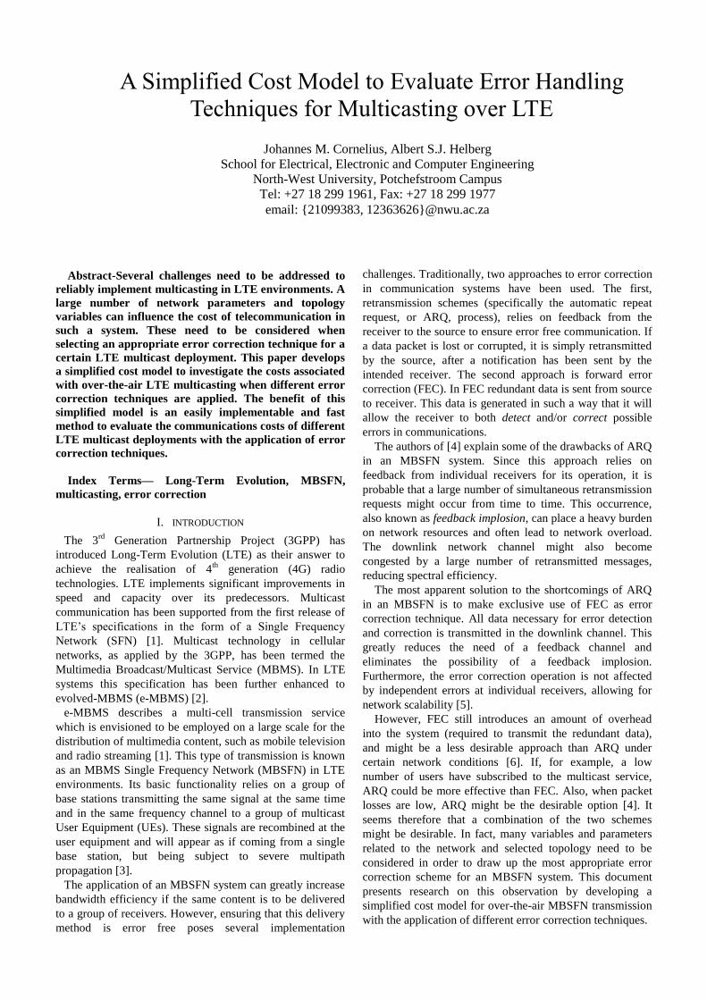
Abstract-Several challenges need to be addressed to
reliably implement multicasting in LTE environments. A
large number of network parameters and topology
variables can influence the cost of telecommunication in
such a system. These need to be considered when
selecting an appropriate error correction technique for a
certain LTE multicast deployment. This paper develops
a simplified cost model to investigate the costs associated
with over-the-air LTE multicasting when different error
correction techniques are applied. The benefit of this
simplified model is an easily implementable and fast
method to evaluate the communications costs of different
LTE multicast deployments with the application of error
correction techniques.
Index Terms— Long-Term Evolution, MBSFN,
multicasting, error correction
I. INTRODUCTION
The 3rd
Generation Partnership Project (3GPP) has
introduced Long-Term Evolution (LTE) as their answer to
achieve the realisation of 4th
generation (4G) radio
technologies. LTE implements significant improvements in
speed and capacity over its predecessors. Multicast
communication has been supported from the first release of
LTE’s specifications in the form of a Single Frequency
Network (SFN) [1]. Multicast technology in cellular
networks, as applied by the 3GPP, has been termed the
Multimedia Broadcast/Multicast Service (MBMS). In LTE
systems this specification has been further enhanced to
evolved-MBMS (e-MBMS) [2].
e-MBMS describes a multi-cell transmission service
which is envisioned to be employed on a large scale for the
distribution of multimedia content, such as mobile television
and radio streaming [1]. This type of transmission is known
as an MBMS Single Frequency Network (MBSFN) in LTE
environments. Its basic functionality relies on a group of
base stations transmitting the same signal at the same time
and in the same frequency channel to a group of multicast
User Equipment (UEs). These signals are recombined at the
user equipment and will appear as if coming from a single
base station, but being subject to severe multipath
propagation [3].
The application of an MBSFN system can greatly increase
bandwidth efficiency if the same content is to be delivered
to a group of receivers. However, ensuring that this delivery
method is error free poses several implementation
challenges. Traditionally, two approaches to error correction
in communication systems have been used. The first,
retransmission schemes (specifically the automatic repeat
request, or ARQ, process), relies on feedback from the
receiver to the source to ensure error free communication. If
a data packet is lost or corrupted, it is simply retransmitted
by the source, after a notification has been sent by the
intended receiver. The second approach is forward error
correction (FEC). In FEC redundant data is sent from source
to receiver. This data is generated in such a way that it will
allow the receiver to both detect and/or correct possible
errors in communications.
The authors of [4] explain some of the drawbacks of ARQ
in an MBSFN system. Since this approach relies on
feedback from individual receivers for its operation, it is
probable that a large number of simultaneous retransmission
requests might occur from time to time. This occurrence,
also known as feedback implosion, can place a heavy burden
on network resources and often lead to network overload.
The downlink network channel might also become
congested by a large number of retransmitted messages,
reducing spectral efficiency.
The most apparent solution to the shortcomings of ARQ
in an MBSFN is to make exclusive use of FEC as error
correction technique. All data necessary for error detection
and correction is transmitted in the downlink channel. This
greatly reduces the need of a feedback channel and
eliminates the possibility of a feedback implosion.
Furthermore, the error correction operation is not affected
by independent errors at individual receivers, allowing for
network scalability [5].
However, FEC still introduces an amount of overhead
into the system (required to transmit the redundant data),
and might be a less desirable approach than ARQ under
certain network conditions [6]. If, for example, a low
number of users have subscribed to the multicast service,
ARQ could be more effective than FEC. Also, when packet
losses are low, ARQ might be the desirable option [4]. It
seems therefore that a combination of the two schemes
might be desirable. In fact, many variables and parameters
related to the network and selected topology need to be
considered in order to draw up the most appropriate error
correction scheme for an MBSFN system. This document
presents research on this observation by developing a
simplified cost model for over-the-air MBSFN transmission
with the application of different error correction techniques.
A Simplified Cost Model to Evaluate Error Handling
Techniques for Multicasting over LTE
Johannes M. Cornelius, Albert S.J. Helberg
School for Electrical, Electronic and Computer Engineering
North-West University, Potchefstroom Campus
Tel: +27 18 299 1961, Fax: +27 18 299 1977
email: {21099383, 12363626}@nwu.ac.za

II. BACKGROUND
In this section a simplified cost model for over-the-air
MBSFN transmission is developed and expanded to include
costs associated with error correction techniques. The
following symbols are used throughout this paper (adapted
from [7]):
Table 1: Mathematical symbols
Symbol Explanation
Delivery cost of a single packet over air (Uu)
interface
Total communication cost over air interface
Total number of packets in the MBSFN session
Number of participating e-NBs in MBSFN.
Resource efficiency
Spectral efficiency
A. Forward Error Correction in MBSFN
As already mentioned, FEC relies on redundancy for its
operation. The redundant bits that will allow for eventual
error correction are added through a process called coding.
Coding can loosely be defined as the process of mapping a
set of input bits to a set of the same amount or more output
bits. A set relationship between the output data (with
redundancy) and actual data then allows the receiver to
detect and correct errors [8]. Several such coding schemes
have been put forward, a number of which is discussed in
[8] and [9]. Particularly relevant to a discussion on LTE
multicasting (because it has been endorsed by the 3GPP
themselves) is the class of fountain codes termed Raptor
codes.
Fountain codes can produce a potentially infinite stream
of output symbols for a finite set of input symbols. If a
message containing a set of input symbols is encoded, a
decoding algorithm will be able to recover the original
message from any set of output symbols with .
Raptor (or rapid tornado) codes are the first practically
realizable class of such fountain codes with linear time
encoding and decoding [10].
B. MBSFN Topology
Consider a hexagonal grid consisting of a number of
evolved-Node B (e-NB) cells as illustrated in Figure 1.
We’ll consider a topology similar to this and will adapt a
number of assumptions based on the architectural setup
described in [7]. Firstly, assume the topology is scalable to
include a large number of cells (approaching infinity).
Secondly, assume that multicast users can be located in an
ever increasing area surrounded by each ring of cells
moving outward from the centre cell. That is, we can
consider an infinite series of scenarios, where:
The users are all located in the centre cell
The users are located in the centre cell and the first
ring of six cells surrounding the centre (a total of 7
cells containing UEs).
The users are located in the centre cell, the first
surrounding ring and the second surrounding ring
of twelve cells (a total of 19 cells).
and so forth, until the users are located in an infinite number
of cells in an infinitely large topology.
Figure 1: A hexagonal grid of cells (Source: Own
construction)
For each scenario, it is possible to enhance the spectral
efficiency of the MBSFN system significantly by having the
ring of cells neighbouring the “inner” area containing UEs
also participate (assist) in the MBSFN transmission
[11],[12]. Although this assisting ring does not contain any
users subscribed to the multicast service, it will broadcast
the same MBSFN data at the same frequency as the inner
cells containing subscribed UEs. In fact, substantial gains in
spectral efficiency can be achieved if up to three
neighbouring rings of cells assist in the MBSFN
transmission [11]. In figure 1, the central seven cells contain
UEs (shaded). They are surrounded by two assistive rings
(striped), broadcasting the same data at the same frequency,
but not containing any subscribed multicast users. The outer
ring in the figure (blocks) does not participate in the
MBSFN session and is termed an interference ring. For the
purposes of this research document, three different
deployments are considered:
AII - One ring of cells neighbouring the area
containing UEs participate in the MBSFN session.
The other cells act as interference rings.
AAI - This is the setup illustrated in the figure.
The first two neighbouring rings surrounding the
area of subscribed users assist in the MBFSN
system, while the outer rings act as interference.
AAA - All three neighbouring cell rings assist in
the multicast. Cell rings further away from the
central cells than the first three neighbouring rings
can be shown to have no significant effect on the
MBSFN transmission [12].
A simplified MBSFN cost model is developed to
accommodate scenarios where the Inter Site Distance
(ISD) between the cells are 500m and 1732m respectively
(termed macro Case 1 and macro Case 2). These are
typical selections based on the Okamura-Hata propagation
model [7], [11].

C. Transmission cost over the air interface
Consider the following equation:
(1)
The total communication cost over the air interface is the
product of the delivery cost for a single packet over the air
interface with the total number of data packets in the
MBSFN session. This product is then multiplied by the
number of e-NBs participating in the MBSFN transmission,
[7]. This number is dependent on both the user
distribution and selected topology of the MBSFN system.
The user distribution is an indication of the number of cells
containing participating UEs, while the selected topology
will determine how many e-NBs from assistive cell rings
(not containing any participating UEs) will participate in the
MBSFN session. The sum of these two indicators is the total
number of participating e-NBs.
Both and are invariable for each modelling
scenario and will be explicitly defined for each case
considered. However, the cost for a single packet over the
air interface, , needs to be modelled mathematically. To
do so we define a resource efficiency variable, RE. Resource
efficiency is defined as the spectral efficiency for a certain
topology, normalized (or multiplied) by the fraction of cells
participating in MBSFN transmission that actually contains
active UEs. For example, if in the hexagonal grid of cells
only the centre cell contains UEs, but there are two assistive
rings of cells, a total of 1 + 6*1 + 6*2 = 19 cells participate
in MBSFN transmission. Even though only one cell (the
centre) contains UEs interested in the MBSFN content, a
total of 19 cells actually participate in the transmission. This
is not a very efficient use of resources and will result in the
spectral efficiency being divided by 19 (multiplied by 1/19)
to compute the resource efficiency (in bps/Hz/cell) [11].
Therefore,
∑
∑
(2)
In the above equation, RE is the resource efficiency and SE
the spectral efficiency for the selected topology. The
summation limits k and n are respectively the number of cell
rings (excluding the centre cell) containing UEs and the
total number of cell rings participating. The k and n-indices
relate to each other in a different way for each considered
topology.
For AII:
For AAI:
For AAA:
The spectral efficiency depends on the propagation model
and specific evaluation scenario. This can be modelled using
the Okamura-Hata model and considering a complex system
of variables. To adhere to the scope of this document, the
values in Table 2 are used, as provided in [11] for Case 1
and Case 3 (Inter Site Distances of 500m and 1732m
respectively). These values were calculated at a 95%
coverage level of the central cell.
Table 2: Spectral Efficiency for MBSFN deployments
SPECTRAL EFFICIENCY
Case 1 (bps/Hz) Case 3 (bps/Hz) Ring
1 2 3
2.4 0.8 A A A
2.2 0.8 A A I
1.3 0.7 A I I
In order to convert the resource efficiency to an indicator
of the relative cost of transmission over the air interface, a
normalized version of the resource efficiency, , is
defined. The resource efficiency of the current deployment
is normalized to the maximum obtainable resource
efficiency for each macro case, namely 2.4 bps/Hz/cell for
Case 1 and 0.8 bps/Hz/cell for Case 3 [7].
(3)
Noting that the cost of transmission increases
proportionally with a decrease in resource efficiency (and
vice versa), the authors of [7] defined the cost of a single
packet delivery over the air interface as:
(4)
The combination of the above equations with the original
cost expression in Equation 1 results in a complete
mathematical model for the cost of packet delivery over the
air interface in an MBSFN system.
D. Error correction costs
1) ARQ Costs
We now extend the cost model presented above to
accommodate for possible errors occurring during MBSFN
transmission and the application of different error correction
techniques to remedy this. If the unit cost for transmitting a
data packet over the air interface is given by and the
total number of packets in the simulation session is , the
total transmission cost (at each participating e-NB) can
be determined as follows:
(5)
The application of error correction techniques can be
modelled by computing the total number of packets lost
during transmission. A distinction should be made between
global losses and local losses. Global losses affect all users
participating in the multicast session (e.g. in the case of
outages) and are independent of the number of multicast
users in the topology. Local losses occur because of
individual errors at local receivers and increase in number as
the number of multicast users in the topology increases. To
illustrate, assume the nominal packet loss rate is 5%. If 90%
of the lost packets affect all users (globally) and 10% of
losses are due to individual errors at receivers, the global
packet loss rate is 4.5% and the local packet loss rate 0.5%.
The typical error correction remedy for both types of lost
packets will be to retransmit the lost packets (to all
registered multicast UEs in the topology, in the case of
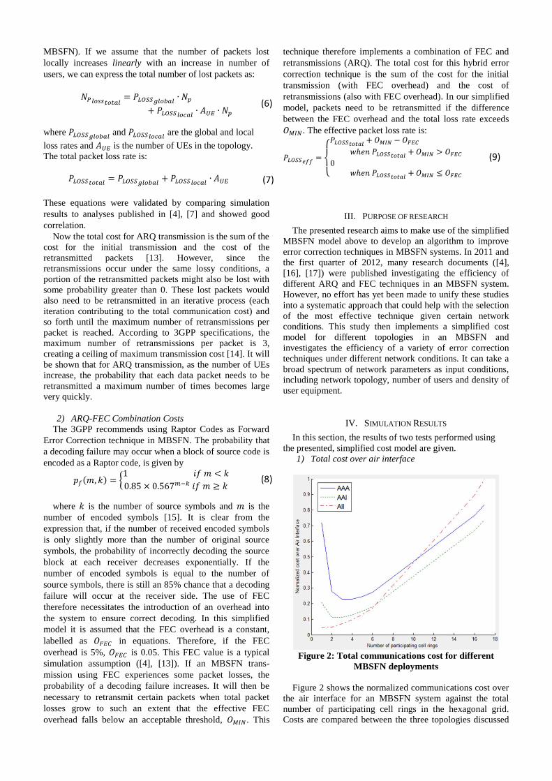
MBSFN). If we assume that the number of packets lost
locally increases linearly with an increase in number of
users, we can express the total number of lost packets as:
(6)
where and
are the global and local
loss rates and is the number of UEs in the topology.
The total packet loss rate is:
(7)
These equations were validated by comparing simulation
results to analyses published in [4], [7] and showed good
correlation.
Now the total cost for ARQ transmission is the sum of the
cost for the initial transmission and the cost of the
retransmitted packets [13]. However, since the
retransmissions occur under the same lossy conditions, a
portion of the retransmitted packets might also be lost with
some probability greater than 0. These lost packets would
also need to be retransmitted in an iterative process (each
iteration contributing to the total communication cost) and
so forth until the maximum number of retransmissions per
packet is reached. According to 3GPP specifications, the
maximum number of retransmissions per packet is 3,
creating a ceiling of maximum transmission cost [14]. It will
be shown that for ARQ transmission, as the number of UEs
increase, the probability that each data packet needs to be
retransmitted a maximum number of times becomes large
very quickly.
2) ARQ-FEC Combination Costs
The 3GPP recommends using Raptor Codes as Forward
Error Correction technique in MBSFN. The probability that
a decoding failure may occur when a block of source code is
encoded as a Raptor code, is given by
{
(8)
where is the number of source symbols and is the
number of encoded symbols [15]. It is clear from the
expression that, if the number of received encoded symbols
is only slightly more than the number of original source
symbols, the probability of incorrectly decoding the source
block at each receiver decreases exponentially. If the
number of encoded symbols is equal to the number of
source symbols, there is still an 85% chance that a decoding
failure will occur at the receiver side. The use of FEC
therefore necessitates the introduction of an overhead into
the system to ensure correct decoding. In this simplified
model it is assumed that the FEC overhead is a constant,
labelled as in equations. Therefore, if the FEC
overhead is 5%, is 0.05. This FEC value is a typical
simulation assumption ([4], [13]). If an MBSFN trans-
mission using FEC experiences some packet losses, the
probability of a decoding failure increases. It will then be
necessary to retransmit certain packets when total packet
losses grow to such an extent that the effective FEC
overhead falls below an acceptable threshold, . This
technique therefore implements a combination of FEC and
retransmissions (ARQ). The total cost for this hybrid error
correction technique is the sum of the cost for the initial
transmission (with FEC overhead) and the cost of
retransmissions (also with FEC overhead). In our simplified
model, packets need to be retransmitted if the difference
between the FEC overhead and the total loss rate exceeds
. The effective packet loss rate is:
{
(9)
III. PURPOSE OF RESEARCH
The presented research aims to make use of the simplified
MBSFN model above to develop an algorithm to improve
error correction techniques in MBSFN systems. In 2011 and
the first quarter of 2012, many research documents ([4],
[16], [17]) were published investigating the efficiency of
different ARQ and FEC techniques in an MBSFN system.
However, no effort has yet been made to unify these studies
into a systematic approach that could help with the selection
of the most effective technique given certain network
conditions. This study then implements a simplified cost
model for different topologies in an MBSFN and
investigates the efficiency of a variety of error correction
techniques under different network conditions. It can take a
broad spectrum of network parameters as input conditions,
including network topology, number of users and density of
user equipment.
IV. SIMULATION RESULTS
In this section, the results of two tests performed using
the presented, simplified cost model are given.
1) Total cost over air interface
Figure 2: Total communications cost for different
MBSFN deployments
Figure 2 shows the normalized communications cost over
the air interface for an MBSFN system against the total
number of participating cell rings in the hexagonal grid.
Costs are compared between the three topologies discussed
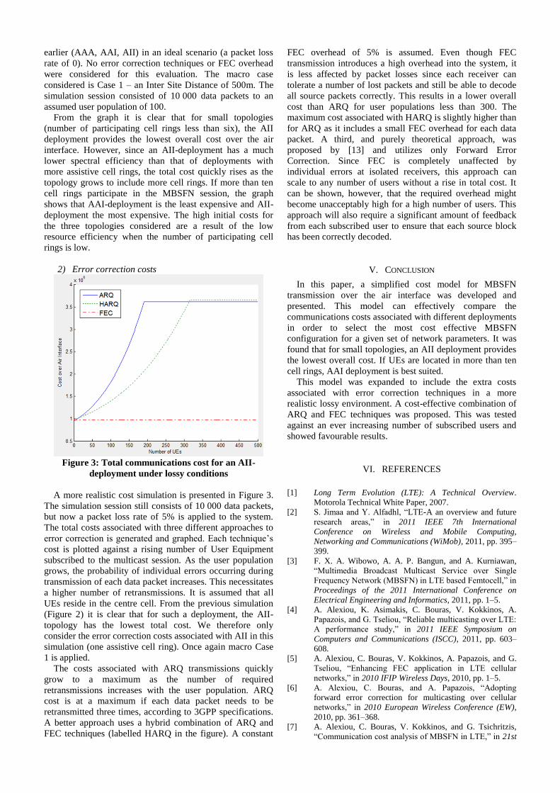
earlier (AAA, AAI, AII) in an ideal scenario (a packet loss
rate of 0). No error correction techniques or FEC overhead
were considered for this evaluation. The macro case
considered is Case 1 – an Inter Site Distance of 500m. The
simulation session consisted of 10 000 data packets to an
assumed user population of 100.
From the graph it is clear that for small topologies
(number of participating cell rings less than six), the AII
deployment provides the lowest overall cost over the air
interface. However, since an AII-deployment has a much
lower spectral efficiency than that of deployments with
more assistive cell rings, the total cost quickly rises as the
topology grows to include more cell rings. If more than ten
cell rings participate in the MBSFN session, the graph
shows that AAI-deployment is the least expensive and AII-
deployment the most expensive. The high initial costs for
the three topologies considered are a result of the low
resource efficiency when the number of participating cell
rings is low.
2) Error correction costs
Figure 3: Total communications cost for an AII-
deployment under lossy conditions
A more realistic cost simulation is presented in Figure 3.
The simulation session still consists of 10 000 data packets,
but now a packet loss rate of 5% is applied to the system.
The total costs associated with three different approaches to
error correction is generated and graphed. Each technique’s
cost is plotted against a rising number of User Equipment
subscribed to the multicast session. As the user population
grows, the probability of individual errors occurring during
transmission of each data packet increases. This necessitates
a higher number of retransmissions. It is assumed that all
UEs reside in the centre cell. From the previous simulation
(Figure 2) it is clear that for such a deployment, the AII-
topology has the lowest total cost. We therefore only
consider the error correction costs associated with AII in this
simulation (one assistive cell ring). Once again macro Case
1 is applied.
The costs associated with ARQ transmissions quickly
grow to a maximum as the number of required
retransmissions increases with the user population. ARQ
cost is at a maximum if each data packet needs to be
retransmitted three times, according to 3GPP specifications.
A better approach uses a hybrid combination of ARQ and
FEC techniques (labelled HARQ in the figure). A constant
FEC overhead of 5% is assumed. Even though FEC
transmission introduces a high overhead into the system, it
is less affected by packet losses since each receiver can
tolerate a number of lost packets and still be able to decode
all source packets correctly. This results in a lower overall
cost than ARQ for user populations less than 300. The
maximum cost associated with HARQ is slightly higher than
for ARQ as it includes a small FEC overhead for each data
packet. A third, and purely theoretical approach, was
proposed by [13] and utilizes only Forward Error
Correction. Since FEC is completely unaffected by
individual errors at isolated receivers, this approach can
scale to any number of users without a rise in total cost. It
can be shown, however, that the required overhead might
become unacceptably high for a high number of users. This
approach will also require a significant amount of feedback
from each subscribed user to ensure that each source block
has been correctly decoded.
V. CONCLUSION
In this paper, a simplified cost model for MBSFN
transmission over the air interface was developed and
presented. This model can effectively compare the
communications costs associated with different deployments
in order to select the most cost effective MBSFN
configuration for a given set of network parameters. It was
found that for small topologies, an AII deployment provides
the lowest overall cost. If UEs are located in more than ten
cell rings, AAI deployment is best suited.
This model was expanded to include the extra costs
associated with error correction techniques in a more
realistic lossy environment. A cost-effective combination of
ARQ and FEC techniques was proposed. This was tested
against an ever increasing number of subscribed users and
showed favourable results.
VI. REFERENCES
[1] Long Term Evolution (LTE): A Technical Overview.
Motorola Technical White Paper, 2007.
[2] S. Jimaa and Y. Alfadhl, “LTE-A an overview and future
research areas,” in 2011 IEEE 7th International
Conference on Wireless and Mobile Computing,
Networking and Communications (WiMob), 2011, pp. 395–
399.
[3] F. X. A. Wibowo, A. A. P. Bangun, and A. Kurniawan,
“Multimedia Broadcast Multicast Service over Single
Frequency Network (MBSFN) in LTE based Femtocell,” in
Proceedings of the 2011 International Conference on
Electrical Engineering and Informatics, 2011, pp. 1–5.
[4] A. Alexiou, K. Asimakis, C. Bouras, V. Kokkinos, A.
Papazois, and G. Tseliou, “Reliable multicasting over LTE:
A performance study,” in 2011 IEEE Symposium on
Computers and Communications (ISCC), 2011, pp. 603–
608.
[5] A. Alexiou, C. Bouras, V. Kokkinos, A. Papazois, and G.
Tseliou, “Enhancing FEC application in LTE cellular
networks,” in 2010 IFIP Wireless Days, 2010, pp. 1–5.
[6] A. Alexiou, C. Bouras, and A. Papazois, “Adopting
forward error correction for multicasting over cellular
networks,” in 2010 European Wireless Conference (EW),
2010, pp. 361–368.
[7] A. Alexiou, C. Bouras, V. Kokkinos, and G. Tsichritzis,
“Communication cost analysis of MBSFN in LTE,” in 21st