an impedance diagram for transmission lines - the … archive/an_impedance...fin impedance diagram...
TRANSCRIPT
fin ImpedanceDiagram forTransmissionLines
THE CUR RENT AND vollage onan unmatched transmission linewill vary along the line . The ratioof the voeane between the linesto the current flowing in them is
termed the line impedance, Z. This ratio varies frompointtc point, asalsodoes thephasedifference between voltage and current. Thevalue of Z at every point is ultimately determined by the load wh ich terminates the ane.which in most cases will be the antenna.Reflect ion et this lerminafion always lakesplace in such a way as loensure thai Zat thispoint is identical to the ecemencea.The lineimpedance 81the othe r end is the impedancewh iCh is presented 10 the transm itter.
The hne impedance Z must nol be ceofused with the characteriStic impedance 01the line, 4
The problem dealt with here is how topredict the variation 01 impedance along anunmatched line, and thus describe how theane acts as a transformer betweenthe transmitler and the antenna, and why this tran sforming ecuon is critical ly depe ndent uponthe length or the line.
The usua l method 01 tackling this sort ofproblem is to employ a Smilh chart and thosewho are familiar w ith its use will find that theope ration rules for the diagram are very sim ilar , O n the other ha nd. there is no need toknow an ylhing abou l a Sm ith chart. Th e diagram is an alternative approach. No specialchart or equipment is nee ded : simply a ruler.a protractor, and a pocke t calculator whichgive s SIN. COS an d TAN.
Vmin
Vmax
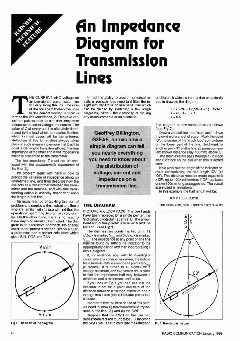
Fig I : The baala gllhe diagram.
42
In fact the ability to predict numerica l resuus is perhaps less impo rtant than the insigh t into transrrnssron line oenawour wh ichcan be gai ned by sketching a lew roughdiag rams, without the necessity of makingany measurements or calculations.
Geoffrey Billington,G3EAE, shows how a
simple diagram can tellyou nearly everything
you need to know aboutthe distribution of
voltage, current andImpedance on a
transmission line.
THE DIAGRAMPICTURE A CLOCK FACE, The two handshave been replaced by a single poin ter , the'indicator', pivo ted at its cen tre,O . The arrowhead en d of this po inter is labe lled Vand thetail en d I (see Fig 1).
The dial has two po ints marked on it: 12o'clock is marked V..... and 6 o'ClOck is markedV_ . The impedanc e at any poinl on lhe linemay be found by sen ing the ind icalor 10 lheappropriate posi lion and then incorpo rating itinlo a diagram.
If, lor instance, you wish 10 inveSll9aleconditions at a voltage maxrmum,the ind icator is turned unlit ee arrowhead points to V_(6 o·clock). II is turned to 12 o'dock lor aYOIIa.geminimum,and to 3 c'cockor 90'dockto find the impedance ha lf way between aminimum and a maeime m, and so on ,
It you look at Fig 1 you can see that theindica lor is set fO( a poinl one-thirtl of thedistance between a VOltage minimum and aVOltage ma xirnum (ie the indica tor pomt s 10 2o'clock ),
In order to find the impedance al this po intwe need to know (i) the characteristic impedance of the line (Ze) an d (ii) meSWA.
Suppose that the SWA on the line hadbeen measured and found to be 3.0. Knowingthe SWA. we use it to calculate the reflec tion
ccetticlent k which is the number we actuallyuse in drawing the diag ram .
k = (SWA - l )/ (SW R ... 1) Note 1k::: (3 -1 )/(3 ... 1)k = 0.5
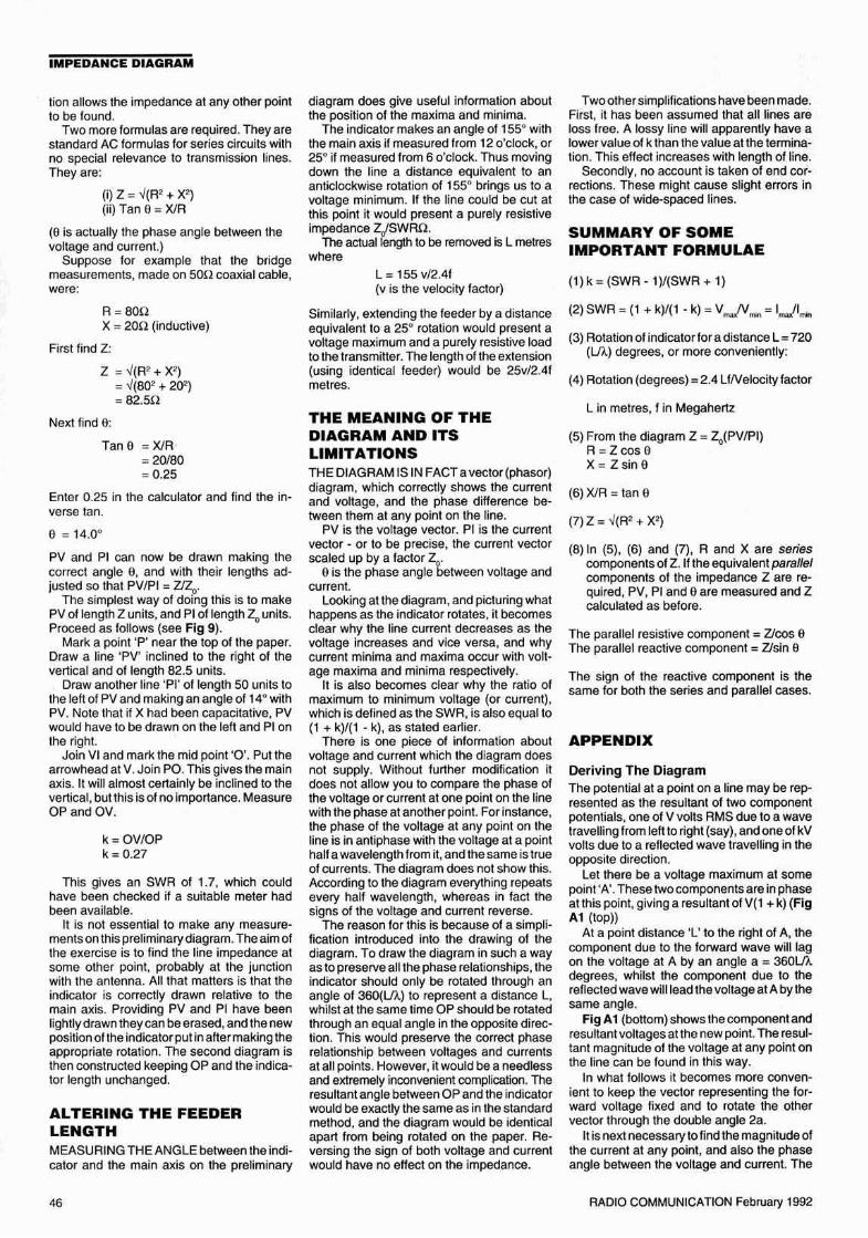
Th e diagram is now coostructed as follows(see Fig 2):
Draw a vertical ~ne - lhe 'main axis' - dow nthe cenlre of a Sheet 01paper. Mark the point-0', the centre of lhe -clock lace ' somewhereon the lower part of the line . NeJ(! mark inanother point 'P' 00 ire line.at someconvenien t known distance (say 100m m) above O.
The main alt is wiDpass through 12 o'dockancl6 o'clock on the dial when this is addedlater.
NeJ(! work out the length of the ind ica tor or.more con veniently, Ihe hall length 'OV (or'Oil. This distance must be made eQual to kIt OP, eg 10 100k minimetres if OP has beendrawn 1OOmm long as sugges ted .The actualsca le used is immaterial.
In this eltarnple the ha ll length will be :
0,5 It 100 ., 50mm.
The clock face. radius 50mm, may now be
Fig 2:The dia gram In ul e.
RADIO COMMUNICATION January 1992

IMPEDANCE DIAGRAM
Fig 3: Another ru le mus t be obe yed.
Z = Zo(PV/P I) = 33UA = Zcos 0 = 33 cos 49 = 22UX e z sm a = aa sro as =25n
p
k
0--+k
p
SWR 0 ' .2k 0 0- 0 9
RlZo = SWR
v
Fig 4: An example.
Fig 5: Impedence e5 . sure res istance .
Conversely, when a line is terminated in apure res istance R which is grea ter tha n ZD
But (1 + k)/( l - k) = SWR (As can be sho wn byrear rang ing the prev ious equation for k). Soat a voltage maximum the impedance is apure resistance R given by
(cos n e 1)(sin 0 = 0)
R =Z cosO =ZX =Z sin O= O
PV = (1 + k) and PI = (1 - k)
V2" = (1 + k)/(l - k)
This agrees with the statement above that ata vollage maximum or min imum , Z is a pureresistance with zero reac tance.
The only remaining question is whethe r Xis inductive or capaciti ve. This is easi ly sellied.
Putt he leiter 'L' on the right hand side of themain axis, and 'C' on the left. utne arrowheadof the indicator lies to the right of the mainaxis , the reactive component is inductive,andif the arrow lies on the left it is capacitive .
In order that this rule works ano ther rulemust be obeyed : movement along the lineewaytrcm the transmi tter end of the feeder isrepresented by an anl iclockwlse rotation ofme indicator. Movement along the line 10wards the transmi tter is repres ented by aclockwise rotation .The rules are summarisedin Fig 3 . (These same rules are employedwhen using a Smith chart).
Before explaining ho w to use the diag ramto solve numerical problems. it is worthwhilelooking at a le w of the many ways in which itcan shed ligh t on transmission line behaviour.
IMPEDANCES AT VOLTAGEMAXIMA AND MINIMANEXT CONSIDER WHAT THE diagram hasto say about the impedances (resistances) atthe ma xima and minima. In Fig 5 OP is takenas one uni t long, and the ind icator half lengthis therefore k units.At a voltage maximum
this occurs. At all otnerpomts Z nas a reactiveas well as a resist ive component. Picturinghow PV and PI change as the indicator rotate s also sho ws that the line impedance hasits maximum and minimum values at a voltage ma ximum and voltage minimu m resoecnvety .
Note that because a= 0 at a voltage maximum or min imum, the equat ions give
THE MATCHED LINE (K = OJIF A LINE IS MA TCHED by termination in apure resistance equ al to its characteristicimpedance 2",there will be no reflection fromthe term ination, ie the SWR = 1, and k = O.
To demonstrate how this affects the diagram it is easiest to cons ider first what happens when k is very small. H is then easy tosee what will happen il k is made smaller andsmaller, eventually becoming zero.
F ig 4 shows an example where the SWR =1.2 and k = 0.09. It is clear that whatever thepos ition 01the indicator, PV/PI is never verydil!erent from uni ty , and the ang le betweenPV and PI is always sma ll. This means thatthe imp edance lo r any leng th 01line is closeto Zo and has a negligible reactive component
In the limiting case of k = u.me length 01theindicator dwind les to zero , so PV and PI arealwa ys the same length, and always lie oneon top 01 the other: Z is always equal to ZO'and is always a pure resis tance. The line ismatched.
% ardSAnt
Towa~h
FINDING ZTO FINO Z, MEASUAE PV and PI and workout (PV/PI ),
The n ~ = (PV/P I)Or Z = Zo(PV/P I)
In the given example (Fig 2). (PV/PI) =0 ,655, so the impeda nce is 0. 655 mult ipliedby the charac teristic impedance of the line.For 50n coaxial cable, lor instance, the rmceoence at th is point will be 32. 75u ,say 33U.
However, knowi ng Z is not a lot 01 use.What is needed for pract ical purpos es is theval ue of the resistive component (A) andreactive com pon ent (X). To find these quan tit ies, the angle abetween PV and PI must bemeasured (Note 3) .
In the example sho wn, a= 49°. A and X arethen found as renews: First lind Z as prevlously explained .
roughly sketched in (Note 2), and the indicator drawn accurately to size and making thecorrec t angle with the main axis. As theindicator sho uld po int at2 o'clock, the anglemad e with the main axis is 180/3 = 60°, Thediagram is com pleted by joining the tip andthe tail of the ind icator to point P (see Fi g 2).
Towa r dS~:~~::""'~Tx -- "<rewardsAnt
Z is equ ivalent to a resistance A and a reactance X connected in series (whether X iscapaci tive or inductive is exp lained tater.j
In order to understand the above equationsoetter.picture wh at happens when the ind icato r is rotated ,The leng ths PV and PI change,sho wing that Z changes, and the angle be tween them (tl) opens out and then closes upagain.
Put non -mathematically, the grea te r theeocree.the greateris the reacti ve com pon ent(X) compared to the resistive component (A).Whe n 0 = 0 the reactive compon en t is zeroand Z is a pure resistance.
Whe n the indica tor is set to V.... or to V"", ,PV and PI lie together, so e = 0 at these twopo ints and Z is a pure resistance. These arethe only po ints on an unmatched line wh ere
RADIO COMMUNICATION January 1992

IMPEDANCE DIAGRAM
Fig 6: Perfectly lllfle<:tln!il termln etlon •.
Fig 7: k Ie . lIghtly le88 than unity .
(i) k = (SWR - 1)/SWR + 1)
Rearranging this gives:
(ii) SWR = (1 + k)/(1 - k).
Both versions are used in this article.
Note 2: There is no real necessity to draw theclock face , but it's not a bad idea to sketch itin.
Note 3: a is in fact the phase difference between the line yoltage and current.
Note 4 : This is always true for the angle between two lines drawn Irom a point on thecircumference to the ends 01 a diameter (theind icato r in th is case) ,
NOTESNote 1: There are two versions of th is fo rmula:
NEXT MONTH • •IN PART 2, G3EAE goes th rough aworked example.
which fulf ils the required condi tion of a vonage maximum or minimum at the dri ven end.
FINDING THE ROTATIONALL TH E PREVIOUS results are of a generalnature, and have been obtained without drawing any diagrams to sca le or making measurements. Before applying the metho d tonumerical problems, more should be saidabout de termining the angle through whichthe indicator must be moved. So far, all discussion has been in terms ofwayeieng th , butit is mo re convenrent u the rotation angle canbe found from the frequ ency of the transmitter.
It can be shown that the rota tion (degrees)representing a length of L metres of tine whe nthe frequency is f mega hertz is given by :
Angular rota tion (deg rees)= 2.4 Lff(yelocity facto r)
Th is may be derived as follow s. A movementof one wavelength Is represen ted by turningthe indicator through two complete rotations:720° . (The reason lo r the unexpected facto r01 two is mentioned in the l inal sec tion :'Mea ning of the Diagram and its Limitations').
In general, a leng th L is represented by arotation of 720 (Lf....) deg rees. f.. is the wavelenglh onthe line'.This is usu ally less than thefree space wavelenqm and is given by
f.. = (300 )(velocity factor)!f
where f.. is in met res, and f in megahertz.Combining the se two formu las gives the tormula stat ed above :
Angular rotation (degrees)= 2.4 L1!(yelocity lactor)
The velocity factor depends upon the type01 tine use d. For open-wire feeders it may betaken as unity, which means tha t you canforget it. For many common sol id dielectr ictypes of coaxial cable !t is 0.66, though theligure for cable with air spac es in the dielect ricis likely to be higher, and must be ascertained.
L
L
o
90·
o
c
c
v
(b)
(a)
p
p
generato r, the behaviour of the line is verysimila r to that of a para llel-tuned ci rcuit, withthe impedance peaking up to a high resistivevalue at resonance. The impe dance will becapacitive on one side of resonance, andinductive on the other. Similarly, if the linepresents a vcltaqe minim um to the generato r,it behaves as a series-tuned circuit.
Of cou rse the main difference betweenresonant lines and tuned circuits is that asimple LC ci rcuit may (ideally) only have oneresonant frequency. This can never be thecase with transmission lines, where reso nance can be obtained with any frequency
PERFECTLY REFLECTINGTERMINATIONS (K = 1)K IS EQUAL TO UNITY (and the SWR isinfinite) when a line is terminated by a perfectreflector which absorbs no energy, for instance an open-circu it, a short-circuit or apure reactance. Figs 6(a) and 6(b) illustratecases where k = 1. OP is equal to the halflength of the indicator, so 'P' is situated cnmerim of the 'dial', and because of this it turns outthat the angle a isa right angle for all settingsof the matcetor (Nate 4).
Since sin 90 =1 and cas 90 =0, Z is aiwaysa pure reactance with no resistive componenl. A length 01 open-circuit or short-cir cuited transmission line behaves as either acapacitor or an inductor. depending upon itslength.
Now think about what happens at a voueceminimum. As the indica tor approaches 12o'clock , the length PV dwindles to zero . Thus(PV/PI) becomes zero at this point, and sodoes Z. Fairly obviously, this must apply atthe short-circuit termination.
In a similar way PI becomes zero at avcltaqe max imum which means that (PV/PI)becomes infinite and so does Z. An opencircu it termination must be a vcnece maximum.
The impedance (reactance) of any lengthof open-circuit or short-circuit length of linemay be found by selting the indicator to 12o'clock lor a short-circu it, or 6 o'clock for anopen -ci rcuit , and rotating the indicato r clockwise through the angle which represents thelength of line .
The reader may feel unhappy about theprediction that Ior lines te rminated in a certectreuectcr, the impedance will be infinite at avcnecemaximum and zero at a Voltage minimum. Clearly this can never qu ite happen inpractice. T here must always be some slightloss of energy on the line or at the te rminationand this will creveonne ideal state from beingrealised.
A mare realistic diag ram is obtained if k isassumed to be very slightly less than unity, Inthis case the point P will lie just outside thecircle as illustraled in Fig 7,
At 12 o'clock and at 6 o'c lock PV and PIswing into line and the impedance convertsIntc a pure res istance; a very high resis tanceat the vcuece maximum and a very low resistance at the voltage minimum. At points not inthe vicinity of a maximum or a minimum thediagram is almost ind istinguishable from thecase when k = 1. The angle between PV andPI is nearly a right angle, so Z is very nearlya pure reactance.
Th is clearly explains how open-circuit andsho rt-circuit lines can e)(hibit resonance, inthe same sort of way as a tuned circuit containing a co il and capacitor.
If it is arranged that an open-circuit or shortcircu it line presents a voltage maximum to a
there wi ll be a vcitaqe ma ximum at the terminat ion and the SWR will be equal to RlZo'
Apply ing similar arguments to a voltaqeminimum you can show that the impedancej again a pure resistance) is equal to Zrl SW R,or conversely, if the line is terminated with ares istance R wh ich is less than ~, the re willbe a voltaqe minimum at the term ination andthe SWR will be equa l to Z,jR .
RADlO COMMUNICATION January 1992

fin ImpedanceDiagram forTransmissionLines
Fig 8: Vecto r diag,am ro, li",t e u mple .
Flg9: Allemalin ,e p,esentatio n o l iine lmpedane:t!.
OP : 65·5mmQV: 18 'Q mm
v
v
,,'
p
p
I
~Io
\
o
Geoffrey Billington,G3EAE, concludeswith some practical
solutions toImpedance matching
problems
Reactive component X =52.2 sin 11 = 10.0U
DRAWING THE DIAGRAM 'INREVERSE'SOMETIMES THE REStSTIVE and react ivecomponents of the line impedance at thetransmitte r end otihe feed er may be de termined usin g a br idge. It is sli tl possible to drawa diagram in reverse wh ich will fill. the lengthan d sett ing entre indi cator atthis point. Oncethis has been done, a rotation from this posi-
The indica tor arrowhead is on the rightof OPso the reac tance is inductive.Note that the diagram ma y equall y well beused to l ind th e equivalent pa rallel comb inal ion of resistance and reactance. Th is isexplained later in section (8) of the form ulasummary.
If the figures for the feeder and antennahad been revers ed , ie il a sou line had beenused wilha 75U restsnve load, the load wouldhave been greater than the characteristicimpedance of the line so there wou ld be avoltage maximum at the load, though theSWA and k would have the same values asbefore. The indicator wou ld be the samelength, but its initia l posit ion would be at 6o'clock ins tead of at t g o'clock.
W hen the method is going to be applied toopen wire feed ers. it may be possible tolocate a maxjmurn or mini mum poin t at ameasurable distance I rom the end 01 thefeeder , using some sort 01probe . Th e inilialposition of the indicator may then be set forthis point il desired. If both a minimum and ama ximum po int areavailable. and if theprobehas a linear response, the ratio of the ma ximum to the mini mum reading gives the SWR ,and you then ha ve me inlormation to li nd boththe imped ance pre sen ted to the tran smitterand the antenna impedance.
To USE THE DIAGRAM 10solveaspecific problem there must besuff icient inform atio n ava ilable todraw the indica tor 01 the correctlength and in the correc t position
for one point on the line. To find the impedance at another point the indicator must berotated to il s new posit ion and a diagram thenconstruc ted . The following problem illustratessome 01 the points which have been introduced.
An antenna has a teed-point impedancewhich is a pure res istanc e of SOU al tha operatinglrequency of 7.1MHz.ll isfe dwith a 15mlength of 75.n coaxial cable, velocity tactor0.66. Find the impedance presented to thetransmitter.
As the termination is a pure resistance ofsou and the characteristic impedance cttheline is 7511, we know :
(i) The antenna end ot the line is a volta geminimum . and
This gives
k = (SW R - l )1(SWR + 1)= 0.512.5 = 0.2
so PVIPI = 0.696 and 0 = 11°.
(ii) The SWR is 75f50 = 1.5
PV = 82.5m mPI =11 8.5mm
Z = 0.696 K 75 = 52.2 U
Resistive component R =52.2cos 11=51.2U
As the antenna en d of the feeder is a vo ltageminimum the initial position of the ind ica tor isat 12 o'clock. The ang le through wh ich theindicato r mus t be rotated is
2.4 L1/0. 66 = (2 .4 x 15 K 7.1)/0.66= 3870
where L is the length of line (melres) betweenthe antenna an d the transmnter.
Th e direc tion of rotalion is clockwise as wewa nt to lind the transformation produced bymoving towards the transmitter. The diagramis shown in Fig 8.
OP is drawn an y con venient len gth (sayl 00mm). Each half 01 the indicator is then20m m long A rotation of 387° is one fullrotauon 01 360 0 plus a furt her 27" . All thatneed be done is to rotate the indicatorthrough27 0 (clockwise , from 12 o'clock) . From thediagram
RADIO COMMUNICATION February 1992 45
IMPEDANCE DIAGRAM
tion allows the impedance at any other pointto be lound.
Two more lormulas are required. They arestandard AC formulas for series circuits withno specia l relevance 10 transmission lines.They are:
(i) Z :: .,I(R2+ X~)
(ii) Tan 0 :: XlR
(0 is actually lhe phase angle between thevoltage and current.)
Suppose for example that the bridgemeasurements, made on 50n coaxial cable,were :
R =80nX= 20n (induct ive)
First find Z:
Z = .,I(R?+ X2)= ,1(8cY + 2cY)= 82.5!!
Next find fl:
rane = Xl R:: 20180= 0.25
Enter 0 .25 in the calcu lator and find the inverse tan.
9 = 14.0"
PV and PI can now be drawn making thecorrect angle e. and with their lengths adjuste d so that PV/PI = ZJZ".
The simplest way of doin g this is to makePV of lenglh Z units. and PI of length z" units.Proceed as follows (see Fig 9).
Mark a pomtP' near the top 01the paper.Draw a line 'PV' inclined to the right of thevertical and 01length 82.5 units.
Draw another line 'PI' of length 50 units tothe left of PV and making an angle of 14" withPV. Note that if X had been capacitative, PVwould have to be drawn on the left and Pionthe right.
Join VI and mark the mid point '0 '. Put thearrowhead at V. Join PO. This gives the mainaxis. It will almost certainly be inclined to thevertic al ,butuus isol no importance. MeasureOP andOV.
k :: OV/OPk :: 0.27
This gives an SWR 01 1.7, which couldhave been checked if a suitable meter hadbeen available .
It is nor essential to make any measurementson this prel iminary diagram.The aim ofthe exercise is to lind the line impeda nce atsome other point , probably at the junctionwith the antenna. All that matters is that theindtcator is correctly drawn relative 10 themain axis. Providing PV and PI have beenlightly drawn they can be erased,and the newposlnon of the indica tor put in after making theappropriate rotation. The second diagram isthen construc ted keeping OP and the indicator length uncha nged.
ALTERING THE FEEDERLENGTHMEASURING THE ANGLE between the indicator and the main axis on the prelim inary
"
diagram does give useful information aboutthe position of the maxima and minima.
The indicator makes an angle 01 155" wilhthe ma in axis if measured from 12 o'clock, or25" if measur ed lrom 6 o'clock . Thus movingdown Ihe line a distance equivalent 10 anant iclockwise rotation of 155" brings us 10 avoltage minimum. If the line cou ld be cut atth is point if would present a purely resistiveimpedance Z.,ISWRU .
The actual length to be removed is L metreswhere
L :: 155 vf2Af(v is the velocity factor)
Similarly , extending the feeder by a distanceequivalent to a 25" rotation would present avol tage maximum and a purely resistive loadto the transmitte r. The length of the extension(using identical feeder) would be 25vl2. 4fmetres.
THE MEANING OF THEDIAGRAM AND ITSLIMITATIONSTHE DIAGRAM IS IN FACT a vectcrtcr eecndiagram, which co rrectly shows the currentand voltage, and the phase difference between them at any point on the line.
PV is the voltage vector. PI is the currentvector - or to be precise, the cur rent vectorscaled up by a factor 2".
e is the phase angle between voltage andcurrent.
Looking at the diagram,and picturing whathappens as the indicator rotates. it becomesclear why the line current decreases as thevcnece increases and vice versa, and whycurrent minima and maxima occur with voltage maxima and minima respect ively.
It is also becomes clear why the ratio 01maximum to minimum voaaqe (or curren t),which is detinM as the SWR , is also equal to(1 + k)/(1 - k), as stated earl ier.
There is one piece of information aboutvoltage and current which the diagram doesnot supply. Wilhout further modificat ion itdoes not allow you to compare the phase ofthe vol tage or current at one point on the linewith the phase at another poinl. For instance ,the phase of the voltage at any point on theline is in antiphase with the vol tage at a pointhalf a wavelength fro m it,and the same is trueof currents .The diag ram does not show this .According to the diagram everything repeatsevery hall wavele ngth, wherea s in fact thesigns of the voltage and current reverse.
The reason for this is because of a sirnpllncauon introduced into the drawing of thediagram. To draw the diagram in such a wayas topreserve all Ihe phase relationships,theindicator should only be rotated through anangle of 360(Ln.) to represent a distance L,whilst at the same time OP should be rotatedthrough an equa t angle in the opposite direction. This would preserve the correct phaserelationship between voltages and cu rrentsat all points. Howe ver, it would be a needlessand extremely inconvenient complication. Theresultant angle between OP and the indicatorwould be exactly the same as in me standardmethod, and the diagram would be identicalapart from being rotated on the paper. Reversing the sign of both voltage and cur rentwould have no effect on the impedance.
Two other simpl ifications have been made.First, it has been assu med that all lines areloss free. A lossy line wi ll apparently have atower veioe ot k than lhe value at the termination, This effec t increases with length of line.
Secondly, no accou nt is taken of end corrections. These might cause slight errors inthe case 01wide-spaced lines.
SUMMARY OF SOMEIMPORTANT FORMULAE
(1) k :: (SWR - 1)/(SWR + 1)
(2) SWR = (1 + k)/(1 - k) = V....fI/"'" = I....!I"",
(3) aorauonof indicator for a dis tance L = 720(Ln.) degrees, or more convenien tly:
(4) Rota tion (degrees) = 2 .4 LlNelocily factor
L in metres, f in Megahertz
(5) From the diagram Z :: ~(PVfPl )
R =ZcosBX:: Zsin B
(6) XlR :: tan B
(7) Z :: .,I(R· + X' )
(8) In (5), (6) and (7), A and X are seriescomponents of Z. lf the equivalent paralle lcomponents of the impedan ce Z are required, PV, PI and B are measured and Zcalcu lated as before.
The parallel resistive component", Zlcos0The parallel reactive component e Zfsin B
The sign of the reactive component is lhesame lor both the ser ies and paralle l cases.
APPENDIX
Der iv ing The DiagramThe potential at a poinl on a line may be represented as me resultant of two componentpotentials. one of V volts RMS due to a wavetravelling from left to right (say), and one 01kVvolts due to a reflected wave travelling in theoppos ite direction .
Let there be a voltage maximum at somepoint 'A'.These twocomponentsare in phaseat th is point, giving a resultant of V(l + k) (FigA1 (top))
At a point distance 'L' 10 the right of A, thecomponent due to the forward wave will lagon the voltage at A by an angle a :: 360Ln.degrees, whilst the component due to thereflected wave will lead the voltage at Aby thesame angle.
Fig A1 (bonom) shows the component andresultant vclta qes at the new point. The resetlant magnitude of the voltage at any point onthe line can be foun d in this way.
In what follows it becomes more convenient to keep the vecto r representing the lorward voltage fixed and 10 rotate the othervector through the double angle za.
It is next necessary to l ind the magnilude ofthe current at any point, and also the phaseangle between the voltage and current. The
RADIO COMMUNICATION February 1992

IMPEDANCE DIAGRAM
z = ~; r = RlZo;x = XlZo
( >k') ("")ccs e e - -
2k 1+z'Rearrang inggive s
r e z cos ax e z sin e
The ang le '\I is the angle between the indicator and the ma in axi s and should be measured from 12 o'clock, not from 6 o'cl ock.
As an examp le,equations (i) and (i i) can beapplied to so lve the prob lem in the secti on'Drawing the Diagram in Reverse '.
Use (i) to f ind k.
r = 80150 = 1.6x = 20150 = 0.4
-v (1 - 1.6)" + 0.4'b
(1 + 1.6)' + 0.4'
Use (ii) or (iii) to find 41 .
If z is greater than unity the greater angle isthe correct one: if z is smalle r than unitychoose the sma ller angle. If you sketch one ortwo diagrams, remembering that 9 is definedas measured from 12 o'clock, the reas onshould become clear. Applying the rule to thepresent case we see that Z is greate r than ~.
z is greater than unity, so <\I = 155 0 is thecorrect answer.
The impedance z at any other poin t at adistance L metres from the tirst may be found.
The angular rotation must be calculatedusing
(' . k' )
Sin '\1 = xlr 2k
= 0.422: .'\1 = 25° (us ing 'inverse sine ')
There ate in fact two significant va lues of 0\1
corresponding to a given val ue of sin 4>, oneless than 90° and the othe r greater .To ob tainthe latte r va lue , the smaller angle must besubtracted Irom 180°. Th,e ca lcu lator on lygives the smaller va lue , 25° in this case, sothe othe r possible va lue is 155°.
This amb iguity doe s nOI arise when lookingup inverse cosines. l uckily it is ea sy to findthe correct answer. Simp ly eva luate z using:
k = 0.274
angle in deg rees = 2.4 LIN
The new val ue of ~ mus t then be found byrolating the indica tor lrom its pre sent positionthroug h the above an gle in the appropriatedi rection. A rough sketch is a help here.
The new value of z is found usin g theequ atio n (iii).
The resistive and reactive componen ts of zare obtained by using equalion (ii) to find thenew value of 0 and then using
rkV
r'V
L.,,,II,
'---'--lea d I lag,III
p
V
V is the resultant Vo ltage
T is the result an t Curren t
FIg A1: Forwerd end reflect&d \/oltegee.
(1 + r)'+ x'
(1- r), + x'(i) k = -V
Relative impedance =(impedance in n)~ (in H).
(ii) tan 8 = xlr= ( ~)sin ill1 - k'
SOLVING PROBLEMSWITHOUT SCALE DIAGRAMSIF YOU ARE HANDY WITH a pocket catculator, it may be easier to cercotete numericalresults rather than draw a diagram accuratelyto scale. Even so, it is really essential tosketch rough diagrams to help you to monitorwha t you are doing.
Three new formulas are requi red in add ition to those already introduced. These newformulas are slightly simplified by quotingthem in 'normalised' or 'relative' impe danceun its .This means that impedances are givenas multiples of ~.
The reflected wave current mus t be lakenas being in an tiphase with the reflecredwavevoltage.
This may be explained by considering acharged region mov ing 10the right , and thena similar1y charged region moving to the ren.The potenl ials will have the same sign in bothcas es, but the currents must be given opposite signs due 10 the opposite directions ofmolion. n is now possible to draw a voltageparallelogram and a current para llelogramside by side (Fig A2 (lop)).
u m e current paralle logram ISsca led up bya factor Zu. il becomes identical to the vo ltageparallelogram, except that the otherdiagonalisused (FJg A2 (bottom)).Th eanglebetweenthe diagonals is the phase angle between theresultant current and voltage.
The diagram described in the main part ofthe article is derived di rectly from Fig A4 ,which is then inverted to give a closet similarity to a Smith chart.
Thus a res istance of 1000: has a relativeres istance of 2 'zednoughts' when using 500reeder.
These 'no rmalised' qua ntit ies are heredenoted by the appropriate small letter , whilstcapital letters denote the same qu antitiesmeasured in ohms.
These 'relative' or 'normalised ' units are alsoemployed by the Smith chart .
The three formulas are:
current at any point may also be representedas the resultant of two components: the CUf
rent due 10 the forward wave Is of amplitudeVIZ" and tha t due to the reflec ted wave is kVl:le. t he forward wave current is in phase withthe forward wave voltage.
-v 1 +k' -2k cos ill(iii) z =
1 + k' + 2k cos <\I Fig A2: Vollege and eurre" l eompooents.
Again you will need your rough sketc h to seewhether x is inductive or capac itative.
RADIO COMMUNICATION February 1992 47