an experimental study on the inline wave force on a
TRANSCRIPT
Full Terms & Conditions of access and use can be found athttp://www.tandfonline.com/action/journalInformation?journalCode=tsos20
Download by: [Shanghai Jiaotong University] Date: 08 December 2015, At: 21:38
Ships and Offshore Structures
ISSN: 1744-5302 (Print) 1754-212X (Online) Journal homepage: http://www.tandfonline.com/loi/tsos20
An experimental study on the inline wave force ona truncated vertical cylinder
Hong Xiong, Jianmin Yang & Xinliang Tian
To cite this article: Hong Xiong, Jianmin Yang & Xinliang Tian (2015): An experimental study onthe inline wave force on a truncated vertical cylinder, Ships and Offshore Structures
To link to this article: http://dx.doi.org/10.1080/17445302.2015.1114292
Published online: 08 Dec 2015.
Submit your article to this journal
View related articles
View Crossmark data
Ships and Offshore Structures, 2015http://dx.doi.org/10.1080/17445302.2015.1114292
An experimental study on the inline wave force on a truncated vertical cylinder
Hong Xionga,b, Jianmin Yanga,b and Xinliang Tiana,b,∗
aState Key Laboratory of Ocean Engineering, Shanghai Jiao Tong University, Shanghai, P.R. China; bCollaborative Innovation Centerfor Advanced Ship and Deep-Sea Exploration, Shanghai, P.R. China
(Received 20 July 2015; accepted 26 October 2015)
Cylindrical structures are widely used in offshore engineering, such as the hard tank of a spar platform, columns of asemi-submersible, jackets, drilling pipes, risers and so on. Interactions between the waves and offshore structures are of greatimportance for engineering applications. This paper focuses on the inline wave force acting on a truncated vertical circularcylinder. Experimental studies are carried out in the wave tank at Shanghai Jiao Tong University in China. The diameter ofthe cylinder (D) is 10 cm and five submergence depths (hs), i.e., hs= 0.5D, 1D, 2D, 3D, 4D, are considered, respectively.The inline force is found to be influenced by the submerged depth of the cylinder, wave steepness and scatter parameter.High-harmonic wave forces and the second-load cycle are also discussed in the paper.
Keywords: inline wave force; truncated vertical cylinder; submerged depth; second load cycle; high-harmonic forces
1. Introduction
With the development and utilisation of marine energy andresources, more and more artificial structures are designedand constructed for the ocean resource exploitation. Off-shore structures such as wind turbine foundations, drillingpipes and floating vessels are constantly confronted by dan-ger from wave impact. The wave-related problems such aswave run-up, motion response and wave loads of the off-shore structures at sea are the main concern and researchtopics in the ocean engineering community.
In recent times, several attempts have been made toanalyse the wave loads on the vertical circular cylinder.The investigations are both analytical and experimental. Onthe analytical side, Morison equation is applied in small-scale structures and McCamy–Fuchs solution is applied inlarge-scale structures. Both of them are used to calculate thefirst-harmonic force. Molin (1979) and Newman (1996b)have employed a second-order model for calculation of thesecond-harmonic wave force. The objective has been tocapture the wave loads up to the third-harmonic component(Faltinsen, et al 1995; Malenica & Molin 1995; Newman1996a). Fully nonlinear methods have also been developedto analyse this problem (Ferrant 1998). For the truncatedcylinder, Yılmaz and Incecik (1998) studied the analyti-cal solution of the diffraction problem of a group of trun-cated vertical cylinders, Abul-Azm and Williams (1988)have employed a second-order model for calculation of thesecond-harmonic wave force on a truncated cylinder andAbbasnia and Ghiasi (2014) studies a fully nonlinear waveinteraction by NURBS numerical wave tank and accelera-
∗Corresponding author. Email: [email protected].
tion potential. On the experimental side, Huseby and Grue(2000) conducted an experimental investigation of higher-harmonic wave forces on a vertical cylinder. Niedzweckiand Dugga (1992) conducted an experimental investigationof wave run-up and wave forces on a truncated cylinder.Deng (2015) does an experimental investigation on roguewaves and their impacts on a vertical cylinder. Besides,Grue and Huseby (2002) observed that the occurrence ofa ringing event is associated with the presence of a sec-ondary load cycle. Rainey (2007) pointed out that the sec-ondary load cycle is not caused by harmonic forcing but isa strongly nonlinear phenomenon which might be related tolocal wave breaking on the cylinder. Paulsen and Bredmose(2014) applied a numerical model to explain the reason ofthe second loads cycle’s mechanism.
At present, very few people noticed and studied the re-lation between the wave loads and the semi-submerged ver-tical circular cylinder with different submergence depths,especially the flow field around the cylinder. In this study,physical experiments are conducted for regular waves inter-acting with the semi-submerged vertical circular cylinderwith different submergence depth, a typical configurationfor a floating offshore wind turbine foundation. A series ofthe wave cases are conducted with five submergence depths.
2. Experimental equipment and set-up
The physical experiments were conducted in the basin atShanghai Jiao Tong University. The wave tank is 20 mlong, 1 m wide and 1.2 m deep. It is glass-walled at one side
C© 2015 Taylor & Francis
Dow
nloa
ded
by [
Shan
ghai
Jia
oton
g U
nive
rsity
] at
21:
38 0
8 D
ecem
ber
2015
2 H. Xiong et al.
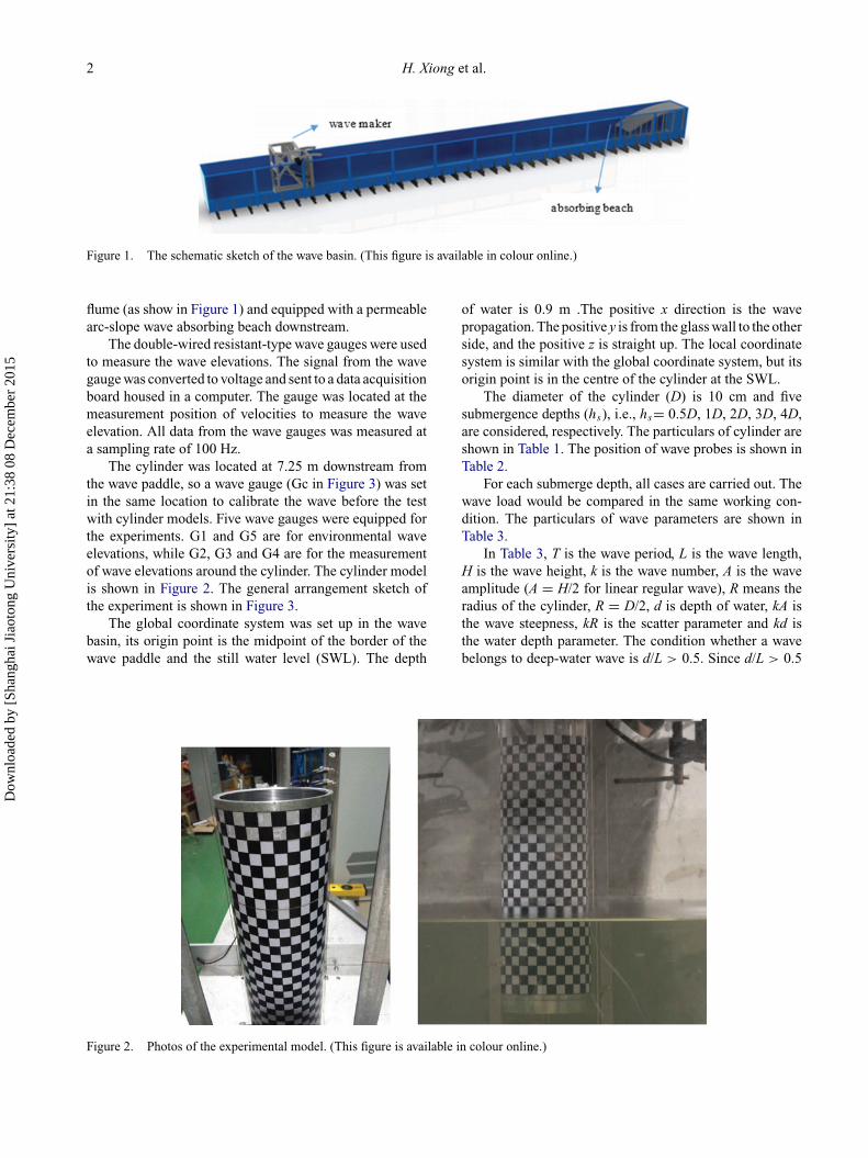
Figure 1. The schematic sketch of the wave basin. (This figure is available in colour online.)
flume (as show in Figure 1) and equipped with a permeablearc-slope wave absorbing beach downstream.
The double-wired resistant-type wave gauges were usedto measure the wave elevations. The signal from the wavegauge was converted to voltage and sent to a data acquisitionboard housed in a computer. The gauge was located at themeasurement position of velocities to measure the waveelevation. All data from the wave gauges was measured ata sampling rate of 100 Hz.
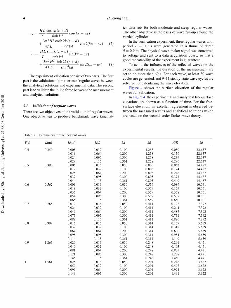
The cylinder was located at 7.25 m downstream fromthe wave paddle, so a wave gauge (Gc in Figure 3) was setin the same location to calibrate the wave before the testwith cylinder models. Five wave gauges were equipped forthe experiments. G1 and G5 are for environmental waveelevations, while G2, G3 and G4 are for the measurementof wave elevations around the cylinder. The cylinder modelis shown in Figure 2. The general arrangement sketch ofthe experiment is shown in Figure 3.
The global coordinate system was set up in the wavebasin, its origin point is the midpoint of the border of thewave paddle and the still water level (SWL). The depth
of water is 0.9 m .The positive x direction is the wavepropagation. The positive y is from the glass wall to the otherside, and the positive z is straight up. The local coordinatesystem is similar with the global coordinate system, but itsorigin point is in the centre of the cylinder at the SWL.
The diameter of the cylinder (D) is 10 cm and fivesubmergence depths (hs), i.e., hs= 0.5D, 1D, 2D, 3D, 4D,are considered, respectively. The particulars of cylinder areshown in Table 1. The position of wave probes is shown inTable 2.
For each submerge depth, all cases are carried out. Thewave load would be compared in the same working con-dition. The particulars of wave parameters are shown inTable 3.
In Table 3, T is the wave period, L is the wave length,H is the wave height, k is the wave number, A is the waveamplitude (A = H/2 for linear regular wave), R means theradius of the cylinder, R = D/2, d is depth of water, kA isthe wave steepness, kR is the scatter parameter and kd isthe water depth parameter. The condition whether a wavebelongs to deep-water wave is d/L > 0.5. Since d/L > 0.5
Figure 2. Photos of the experimental model. (This figure is available in colour online.)
Dow
nloa
ded
by [
Shan
ghai
Jia
oton
g U
nive
rsity
] at
21:
38 0
8 D
ecem
ber
2015

Ships and Offshore Structures 3
Figure 3. The general arrangement sketch (unit: m). G1–G5 are the wave gauges, Gc refers to the gauge for wave calibration. The globalcoordinate system is expressed as red X,Z, and the local coordinate system is expressed as blue x,z. (This figure is available in colour online.)
Table 1. Particulars of the cylinder (unit: cm).
Particulars Value
Diameter 10.00Height 29.4/34.4/44.4/54.4/64.4Submerge depth 5/10/20/30/40
for all cases, satisfying criteria of deep water waves, theregular wave series considered in the present experimentare all deep water waves.
3. Validation studies
According to the linear wave theory, velocity potential ofthe airy wave can be expressed as
φ = gH
2ω
cosh k (z + d)
cosh kdsin(kx − ωt) (1)
where g means the acceleration of gravity. ω is the fre-quency, x and z are the coordinates, so the wave elevation ζ
and velocity can be derived,
ζ = H
2cos (kx0 − ωt) (2)
ux = gHk
2ω
cosh k (z + d)
cosh kdcos(kx − ωt) (3)
uz = gHk
2ω
sinh k (z + d)
cosh kdsin(kx − ωt) (4)
It should be noted that the Airy wave theory is notapplicable for the cases of a large wave steepness orH/d > 0.04. Therefore, the second-order Stokes wave the-ory is used, and the velocity potential of the wave can beexpressed as
φ = HL
2T
cosh k (z + d)
sinh kdsin(kx − ωt)
+ 3πH 2
16T
cosh 2k (z + d)
sinh4kdsin 2(kx − ωt) (5)
Surface elevation and velocity are expressed as
ζ = H
2cos (kx0 − ωt)
+ πH 2
4L
(1 + 3
2sinh2kd
)cothkd cos2 (kx0 − ωt)
(6)
Table 2. Positions of wave gauges.
Gauge#Radial distancefrom wall (m)
Angle from wavedirection (deg) Gauge#
Distance fromwave paddle (m)
Angle from wavedirection (deg)
G2 0.04 0 G1 5 0G3 0.04 90 G5 12 0G4 0.04 180 Gc 7.25 0
Dow
nloa
ded
by [
Shan
ghai
Jia
oton
g U
nive
rsity
] at
21:
38 0
8 D
ecem
ber
2015
4 H. Xiong et al.
ux = HL
T
cosh k (z + d)
sinh kdcos(kx − ωt)
+ 3π2H 2
4T L
cosh 2k (z + d)
sinh4kdcos 2(kx − ωt) (7)
uz = HL
T
sinh k (z + d)
sinh kdsin(kx − ωt)
+ 3π2H 2
4T L
sinh 2k (z + d)
sinh4kdsin 2(kx − ωt) (8)
The experiment validation consist of two parts. The firstpart is the validation of time series of regular waves betweenthe analytical solutions and experimental data. The secondpart is to validate the inline force between the measurementand analytical solutions.
3.1. Validation of regular waves
There are two objectives of the validation of regular waves.One objective was to produce benchmark wave kinemat-
ics data sets for both moderate and steep regular waves.The other objective is the basis of wave run-up around thevertical cylinder.
In the verification experiment, three regular waves withperiod T = 0.9 s were generated in a flume of depthd = 0.9 m. The physical wave-maker signal was convertedto voltage and sent to a data acquisition board, so that agood repeatability of the experiment is guaranteed.
To avoid the influences of the reflected waves on theexperimental results, the duration of the measurement areset to no more than 60 s. For each wave, at least 30 wavecycles are generated, and 9–11 steady-state wave cycles areselected for calculating the wave elevation.
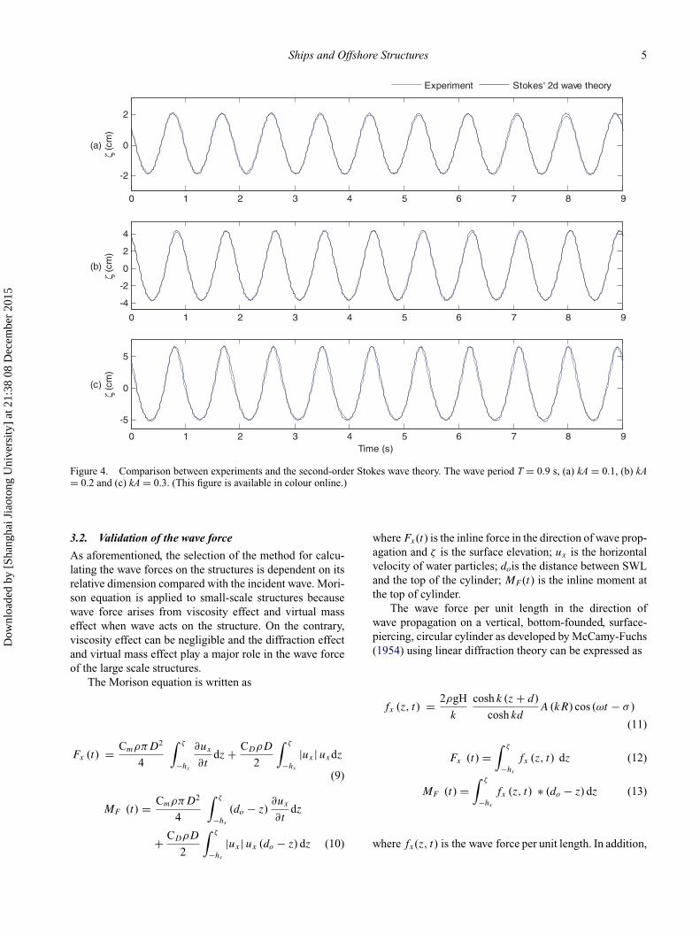
Figure 4 shows the surface elevation of the regularwaves for validation.
In Figure 4, the experimental and analytical free-surfaceelevations are shown as a function of time. For the free-surface elevation, an excellent agreement is observed be-tween the measured results and analytical solutions whichare based on the second- order Stokes wave theory.
Table 3. Parameters for the incident waves.
T(s) L(m) H(m) H/L kA kR A/R kd
0.4 0.250 0.008 0.032 0.100 1.258 0.080 22.6370.016 0.064 0.200 1.258 0.159 22.6370.024 0.095 0.300 1.258 0.239 22.6370.029 0.115 0.361 1.258 0.290 22.637
0.5 0.390 0.006 0.016 0.050 0.805 0.062 14.4870.012 0.032 0.100 0.805 0.124 14.4870.025 0.064 0.200 0.805 0.248 14.4870.037 0.095 0.300 0.805 0.373 14.4870.044 0.115 0.361 0.805 0.440 14.487
0.6 0.562 0.009 0.016 0.050 0.559 0.089 10.0610.018 0.032 0.100 0.559 0.179 10.0610.036 0.064 0.200 0.559 0.358 10.0610.054 0.095 0.300 0.559 0.537 10.0610.065 0.115 0.361 0.559 0.650 10.061
0.7 0.765 0.012 0.016 0.050 0.411 0.122 7.3920.024 0.032 0.100 0.411 0.244 7.3920.049 0.064 0.200 0.411 0.487 7.3920.073 0.095 0.300 0.411 0.731 7.3920.088 0.115 0.361 0.411 0.880 7.392
0.8 0.999 0.016 0.016 0.050 0.314 0.159 5.6590.032 0.032 0.100 0.314 0.318 5.6590.064 0.064 0.200 0.314 0.636 5.6590.095 0.095 0.300 0.314 0.954 5.6590.114 0.115 0.361 0.314 1.140 5.659
0.9 1.265 0.020 0.016 0.050 0.248 0.201 4.4710.040 0.032 0.100 0.248 0.403 4.4710.081 0.064 0.200 0.248 0.805 4.4710.121 0.095 0.300 0.248 1.208 4.4710.145 0.115 0.361 0.248 1.450 4.471
1 1.561 0.025 0.016 0.050 0.201 0.248 3.6220.050 0.032 0.100 0.201 0.497 3.6220.099 0.064 0.200 0.201 0.994 3.6220.149 0.095 0.300 0.201 1.491 3.622
Dow
nloa
ded
by [
Shan
ghai
Jia
oton
g U
nive
rsity
] at
21:
38 0
8 D
ecem
ber
2015
Ships and Offshore Structures 5
0 1 2 3 4 5 6 7 8 9
-2
0
2ζ
(cm
)
(a)
Experiment Stokes' 2d wave theory
0 1 2 3 4 5 6 7 8 9
-4
-2
0
2
4
ζ (c
m)
(b)
0 1 2 3 4 5 6 7 8 9
-5
0
5
ζ (c
m)
(c)
Time (s)
Figure 4. Comparison between experiments and the second-order Stokes wave theory. The wave period T = 0.9 s, (a) kA = 0.1, (b) kA= 0.2 and (c) kA = 0.3. (This figure is available in colour online.)
3.2. Validation of the wave force
As aforementioned, the selection of the method for calcu-lating the wave forces on the structures is dependent on itsrelative dimension compared with the incident wave. Mori-son equation is applied to small-scale structures becausewave force arises from viscosity effect and virtual masseffect when wave acts on the structure. On the contrary,viscosity effect can be negligible and the diffraction effectand virtual mass effect play a major role in the wave forceof the large scale structures.
The Morison equation is written as
Fx (t) = CmρπD2
4
∫ ζ
−hs
∂ux
∂tdz + CDρD
2
∫ ζ
−hs
|ux | uxdz
(9)
MF (t) = CmρπD2
4
∫ ζ
−hs
(do − z)∂ux
∂tdz
+ CDρD
2
∫ ζ
−hs
|ux | ux (do − z) dz (10)
where Fx(t) is the inline force in the direction of wave prop-agation and ζ is the surface elevation; ux is the horizontalvelocity of water particles; dois the distance between SWLand the top of the cylinder; MF (t) is the inline moment atthe top of cylinder.
The wave force per unit length in the direction ofwave propagation on a vertical, bottom-founded, surface-piercing, circular cylinder as developed by McCamy-Fuchs(1954) using linear diffraction theory can be expressed as
fx (z, t) = 2ρgH
k
cosh k (z + d)
cosh kdA (kR) cos (ωt − σ )
(11)
Fx (t) =∫ ζ
−hs
fx (z, t) dz (12)
MF (t) =∫ ζ
−hs
fx (z, t) ∗ (do − z) dz (13)
where fx(z, t) is the wave force per unit length. In addition,
Dow
nloa
ded
by [
Shan
ghai
Jia
oton
g U
nive
rsity
] at
21:
38 0
8 D
ecem
ber
2015

6 H. Xiong et al.
0 1 2 3 4 5 6 7 8 9 10-4
-2
0
2
4in
line
forc
e (N
)
Experiment Morison equation
0 1 2 3 4 5 6 7 8 9 10
-1
-0.5
0
0.5
1
inlin
e m
omen
t (N
*m)
Time (s)
Figure 5. Comparison between experimental results and Morison equation solution. The waves has period T = 1 s, kA = 0.2 and kR =0.2. (This figure is available in colour online.)
0 0.5 1 1.5 2 2.5 3 3.5 4 4.5 5-2
-1
0
1
2
inlin
e fo
rce
(N)
Experiment McCamy-Fuchs solution
0 0.5 1 1.5 2 2.5 3 3.5 4 4.5 5-0.5
-0.25
0
0.25
0.5
inlin
e m
omen
t (N
*m)
Time (s)
Figure 6. Comparison between experimental results and McCamy–Fuchs solution. The waves has period T = 0.5 s, kA = 0.2 and kR =0.805. (This figure is available in colour online.)
Dow
nloa
ded
by [
Shan
ghai
Jia
oton
g U
nive
rsity
] at
21:
38 0
8 D
ecem
ber
2015
Ships and Offshore Structures 7
0 0.2 0.4 0.6 0.8 1 1.2 1.40
0.2
0.4
0.6
0.8
1
1.2
1.4
Scatter Parameter kR
FT'
McCamy-Fuchs solutionkA=0.05
kA=0.1
kA=0.2
kA=0.3kA=0.36
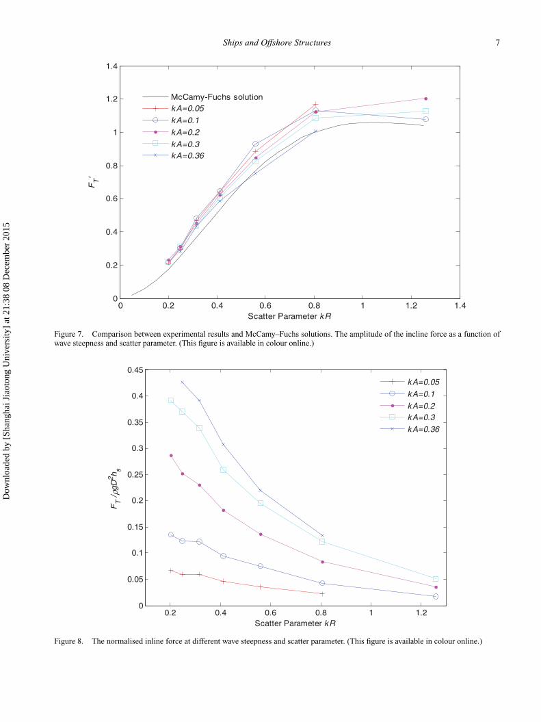
Figure 7. Comparison between experimental results and McCamy–Fuchs solutions. The amplitude of the incline force as a function ofwave steepness and scatter parameter. (This figure is available in colour online.)
0.2 0.4 0.6 0.8 1 1.20
0.05
0.1
0.15
0.2
0.25
0.3
0.35
0.4
0.45
Scatter Parameter kR
FT /
ρgD
2 h s
kA=0.05
kA=0.1
kA=0.2kA=0.3
kA=0.36
Figure 8. The normalised inline force at different wave steepness and scatter parameter. (This figure is available in colour online.)
Dow
nloa
ded
by [
Shan
ghai
Jia
oton
g U
nive
rsity
] at
21:
38 0
8 D
ecem
ber
2015

8 H. Xiong et al.
0 0.2 0.4 0.6 0.8 1 -1.2
-0.8
-0.4
0
0.4
0.8
1.2
Fx /
Fm
ax
(a)
T2
0 0.2 0.4 0.6 0.8 1 -3
-2
-1
0
1
2
3
ζ/A
0 0.2 0.4 0.6 0.8 1 -1.2
-0.8
-0.4
0
0.4
0.8
1.2
Fx /
Fm
ax
(b)
T2
0 0.2 0.4 0.6 0.8 1 -3
-2
-1
0
1
2
3
ζ/A
0 0.2 0.4 0.6 0.8 1 -1.2
-0.8
-0.4
0
0.4
0.8
1.2
Fx /
Fm
ax
(c)
time t/T
0 0.2 0.4 0.6 0.8 1 -3
-2
-1
0
1
2
3
ζ/A
inline force G3 G2 G4
Figure 9. Time histories of the inline force and wave run-up with different wave steepness for the specific scatter parameter kR = 0.248:(a) kA = 0.361; (b) kA = 0.3; (c) kA = 0.2. (This figure is available in colour online.)
A (kR) = 1√J
′21 (kR) + Y
′21 (kR)
(14)
σ = tan−1
[J
′21 (kR)
Y′21 (kR)
](15)
where J′21 (ka) and Y
′21 (ka) are derivatives of Bessel func-
tions of the first and second kind, respectively.The experimental data are measured by a six-
dimensional force transducer located at top of cylinder.The measurements were taken from 10 waves which havereached steady state. Here are the figures which show thewave force and moment in the conditions of two regularwaves with period T = 1 s and T = 0.5 s with the samewave steepness parameter kA = 0.2, and the same submer-gence depth hs=D.
In Figures 5 and 6, the experimental, analytical inlineforce and moment are shown as a function of time. Forthe inline force, a good agreement is observed exceptingthe small differences at valleys. The difference betweenthe experimental and theoretical inline force at the val-leys is due to the wall effect of the diffracted wave (thewave is large and so is diffracted wave) so that the syn-thesis wave height is larger than the incident wave. An-other reason may be due to the higher order components ofthe wave. For inline moment, a similar good agreement isobserved.
As shown in Figure 6, a good agreement is observedfor inline force as the wave is small. The McCamy-Fuchssolution is well applied to the small wave. But for the in-line moment, the measurements are smaller than analyticalvalue.
Dow
nloa
ded
by [
Shan
ghai
Jia
oton
g U
nive
rsity
] at
21:
38 0
8 D
ecem
ber
2015
Ships and Offshore Structures 9
0 0.2 0.4 0.6 0.8 1 -1.2
-0.8
-0.4
0
0.4
0.8
1.2
Fx /
Fm
ax
(a)
0 0.2 0.4 0.6 0.8 1 -1.2
-0.8
-0.4
0
0.4
0.8
1.2
Fx /
Fm
ax
(b)
T2
0 0.2 0.4 0.6 0.8 1 -3
-2
-1
0
1
2
3
ζ/A
0 0.2 0.4 0.6 0.8 1 -3
-2
-1
0
1
2
3
ζ/A
0 0.2 0.4 0.6 0.8 1 -1.2
-0.8
-0.4
0
0.4
0.8
1.2
Fx /
Fm
ax
(c)
time t/T
T2
0 0.2 0.4 0.6 0.8 1 -3
-2
-1
0
1
2
3
ζ/A
inline force G3 G2 G4
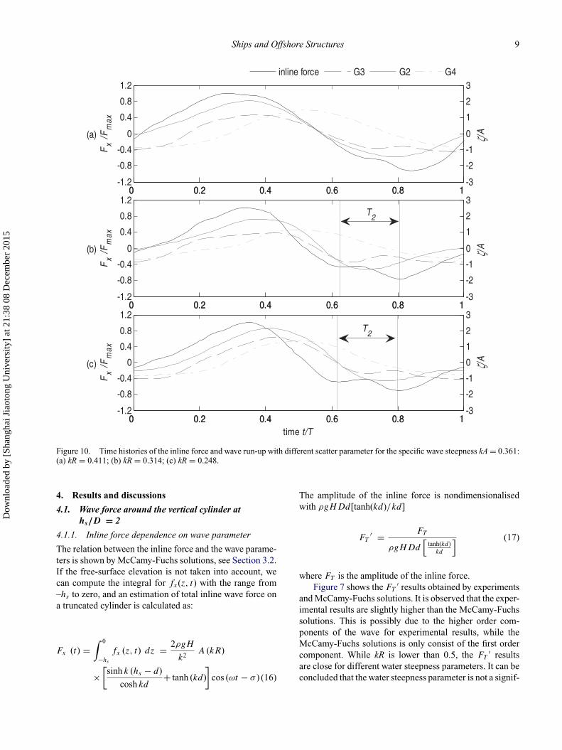
Figure 10. Time histories of the inline force and wave run-up with different scatter parameter for the specific wave steepness kA = 0.361:(a) kR = 0.411; (b) kR = 0.314; (c) kR = 0.248.
4. Results and discussions
4.1. Wave force around the vertical cylinder aths/D = 2
4.1.1. Inline force dependence on wave parameter
The relation between the inline force and the wave parame-ters is shown by McCamy-Fuchs solutions, see Section 3.2.If the free-surface elevation is not taken into account, wecan compute the integral for fx(z, t) with the range from–hs to zero, and an estimation of total inline wave force ona truncated cylinder is calculated as:
Fx (t) =∫ 0
−hs
fx (z, t) dz = 2ρgH
k2A (kR)
×[sinh k (hs − d)
cosh kd+ tanh (kd)
]cos (ωt − σ ) (16)
The amplitude of the inline force is nondimensionalisedwith ρgHDd[tanh(kd)/kd]
FT′ = FT
ρgHDd[
tanh(kd)kd
] (17)
where FT is the amplitude of the inline force.Figure 7 shows the FT
′ results obtained by experimentsand McCamy-Fuchs solutions. It is observed that the exper-imental results are slightly higher than the McCamy-Fuchssolutions. This is possibly due to the higher order com-ponents of the wave for experimental results, while theMcCamy-Fuchs solutions is only consist of the first ordercomponent. While kR is lower than 0.5, the FT
′ resultsare close for different water steepness parameters. It can beconcluded that the water steepness parameter is not a signif-
Dow
nloa
ded
by [
Shan
ghai
Jia
oton
g U
nive
rsity
] at
21:
38 0
8 D
ecem
ber
2015
10 H. Xiong et al.
icant factor when the scatter parameter is small. However,when the kR is above 0.6, the difference for different watersteepness parameter becomes more significant. This rangerepresents the high frequency of the wave measurements,as the high-frequency incident waves are significantly dis-torted by the scatted waves from the cylinders.
In the case of regular waves, a smooth truncated verti-cal circular cylinder is fixed at its top. The hydrodynamicforcing on the cylinder can be considered a function of thefollowing dimensional parameters:
ρ, g,H, hs, d, L,R, ν, t
where t is time and ν is kinematic viscosity. By dimen-sional analysis, the inline force can, therefore, be writtenas a function of six dimensionless parameters: what we re-search is different submergence depths, hs /D is taking intoaccount.
Fx
ρghsR2= f
(H/L, d/L,R/L,
hs
R,
v√gL3
,t√gL
)
(18)
Further, without loss of generality, v/√
gL3 can be replacedby Reynolds number, which could be defined in termsof the maximum horizontal velocity at still water Re =u|z=0 D/v. FT is the amplitude of inline force which is in-dependent on time. Hence, by introducing the wavenumberk = 2π/L, R = D/2, the functional relation for FT duringa wave period can be written as
FT
ρghsD2= f
(kA, kd, kR,
hs
D,Re
)(19)
Besides, the buoyancy force of the semi-submerged verticalcircular cylinder in still water can be expressed as
Fbuo = ρg Vs = π
4ρghsD
2 (20)
So, the relation between the inline force and the buoyancyforce can be expressed as:
FT
Fbuo
= f
(kA, kd, kR,
hs
D,Re
)(21)
where kd ≥ 1, we present that all waves are deep-waterwave. The difference of kd can be neglected.
Figure 8 indicates the relation between the normalisedinline force and wave parameters. For each wave steepness,the normalised inline force decreases as the scatter param-eter increases. The large scatter parameter means the smallwave amplitude when the diameter is constant, and the smallwave mainly acts on the cylinder near the free-elevation.The inline force per unit submergence depth decreases as
the submergence depth increases. But for the specific scat-ter parameter, the normalised inline force on the cylinderincreases as kA increases. This is due to the larger waveamplitude.
4.1.2. The physics of the secondary load cycle
Secondary load cycles have previously been observed andinvestigated by several researchers. Grue (2002) suggestedthat the secondary load cycle is a resonance between a localinduced flow and the cylinder. In Rainey (2007), the sec-ondary load cycle was ascribed to the filling of the down-stream cavity at the back of the cylinder caused by theblockage of the wave crest by the cylinder.
Figure 9 shows the time histories of the inline force andwave run-up with different wave steepness for the specificscatter parameter kR = 0.248. It can be observed that theeffect of wave nonlinearity on the loading history becomesevident by comparison of Figure 9a–c. Here, an additionallocal force peak is seen to build up close to, and during,the time of minimum loading, for increasing values kA.This additional loading will be referred to as a secondaryload cycle with duration T2. The second load cycle showsa dependence on the wave steepness. Only when the kA islarger than a certain value (0.3 in Figure 9) for the specificscatter parameter, the second load cycle would occur. It isconcluded that the second load cycle is partly caused by thewave nonlinearity.
Figure 10 shows the time histories of the inline forceand wave run-up with different scatter parameter for thespecific wave steepness kA = 0.361. It is observed thatthe magnitude of the secondary load cycles is dependenton the scatter parameter. In Figure 10, the magnitude of thesecondary load cycle was seen to be more pronounced in thelong-wave regime, which is consistent with the observationby Grue (2002). The forcing during the passage of the wavecrest was thus similar for all waves, as may be seen inFigure 10, but the flow in the vicinity of the cylinder afterthe passage of the wave crest was different. For decreasingvalues of kR, the nonlinearity in the inline force increases,which is clearly indicated by the asymmetry in the forcesignals. The loading curves before the wave crest passesthe cylinder are similar for all waves by comparison ofFigure 10a–c, but the flow filed in the vicinity of the cylinderafter the wave crest passes the cylinder is different. Thenonlinearity in the inline force increases as kR decreases,which is clearly indicated by the asymmetry at the crest andthoughs in the force signals
4.1.3. Higher harmonic wave forces on a verticalcylinder
Ringing occurs when higher harmonics in the forcing froma large wave excite a natural frequency of a structure in-termittently. Ringing is often associated with the third-
Dow
nloa
ded
by [
Shan
ghai
Jia
oton
g U
nive
rsity
] at
21:
38 0
8 D
ecem
ber
2015

Ships and Offshore Structures 11
0 0.5 1 1.5 2 2.5 3-6
-4
-2
0
2
4
6
8
Fx /
ρgA
R2
1 Harmonic
Inline force
0 0.5 1 1.5 2 2.5 3-6
-4
-2
0
2
4
6
8
1+2 Harmonic
Inline force
0 0.5 1 1.5 2 2.5 3-6
-4
-2
0
2
4
6
8
Fx /
ρgA
R2
1+2+3 Harmonic
Inline force
0 0.5 1 1.5 2 2.5 3-6
-4
-2
0
2
4
6
8
1+2+3+4 Harmonic
Inline force
0 0.5 1 1.5 2 2.5 3-6
-4
-2
0
2
4
6
8
time t/T
Fx /
ρgA
R2
1+2+3+4+5 Harmonic
Inline force
0 0.5 1 1.5 2 2.5 3-6
-4
-2
0
2
4
6
8
time t/T
1+2+3+4+5+6 Harmonic
Inline force
Figure 11. Low-pass filtered force signal as a function of time for an increasing number of included harmonics. A regular wave withT = 0.9 s, kR = 0.248 and kA = 0.361 is considered. (This figure is available in colour online.)
Dow
nloa
ded
by [
Shan
ghai
Jia
oton
g U
nive
rsity
] at
21:
38 0
8 D
ecem
ber
2015
12 H. Xiong et al.
0 1 2 3 40
0.05
0.1
0.15
0.2
0.25
0.3
FT /
ρgh sD
2
0 1 2 3 40
0.05
0.1
0.15
0.2
0.25
0.3
0.35
0 1 2 3 40
0.1
0.2
0.3
0.4
FT /
ρgh sD
2
Submergence Depth Parameter hs/D0 1 2 3 4
0
0.1
0.2
0.3
0.4
0.5
Submergence Depth Parameter hs/D
kA=0.05 kA=0.1 kA=0.2 kA=0.3 kA=0.36
(d)
(b)
(c)
(a)
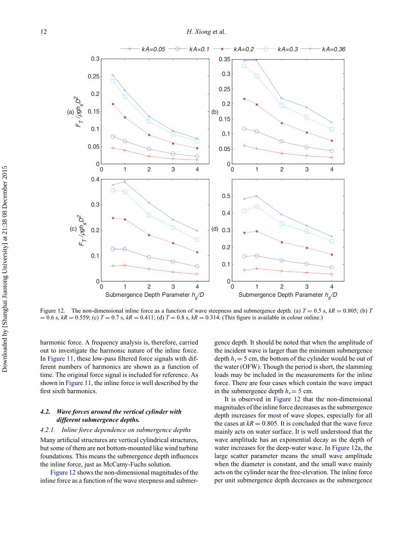
Figure 12. The non-dimensional inline force as a function of wave steepness and submergence depth. (a) T = 0.5 s, kR = 0.805; (b) T= 0.6 s, kR = 0.559; (c) T = 0.7 s, kR = 0.411; (d) T = 0.8 s, kR = 0.314. (This figure is available in colour online.)
harmonic force. A frequency analysis is, therefore, carriedout to investigate the harmonic nature of the inline force.In Figure 11, these low-pass filtered force signals with dif-ferent numbers of harmonics are shown as a function oftime. The original force signal is included for reference. Asshown in Figure 11, the inline force is well described by thefirst sixth harmonics.
4.2. Wave forces around the vertical cylinder withdifferent submergence depths.
4.2.1. Inline force dependence on submergence depths
Many artificial structures are vertical cylindrical structures,but some of them are not bottom-mounted like wind turbinefoundations. This means the submergence depth influencesthe inline force, just as McCamy-Fuchs solution.
Figure 12 shows the non-dimensional magnitudes of theinline force as a function of the wave steepness and submer-
gence depth. It should be noted that when the amplitude ofthe incident wave is larger than the minimum submergencedepth hs= 5 cm, the bottom of the cylinder would be out ofthe water (OFW). Though the period is short, the slammingloads may be included in the measurements for the inlineforce. There are four cases which contain the wave impactin the submergence depth hs= 5 cm.
It is observed in Figure 12 that the non-dimensionalmagnitudes of the inline force decreases as the submergencedepth increases for most of wave slopes, especially for allthe cases at kR = 0.805. It is concluded that the wave forcemainly acts on water surface. It is well understood that thewave amplitude has an exponential decay as the depth ofwater increases for the deep-water wave. In Figure 12a, thelarge scatter parameter means the small wave amplitudewhen the diameter is constant, and the small wave mainlyacts on the cylinder near the free-elevation. The inline forceper unit submergence depth decreases as the submergence
Dow
nloa
ded
by [
Shan
ghai
Jia
oton
g U
nive
rsity
] at
21:
38 0
8 D
ecem
ber
2015
Ships and Offshore Structures 13
0.2 0.4 0.6 0.8 1 1.20
0.05
0.1
0.15
0.2F
T /
ρgh sD
2
0.2 0.4 0.6 0.8 1 1.20
0.05
0.1
0.15
0.2
0.25
0.3
0.35
0.4
← OFW
0.2 0.4 0.6 0.8 1 1.20
0.1
0.2
0.3
0.4
0.5
FT /
ρgh sD
2
Scatter Parameter kR
← OFW
← OFW
0.2 0.4 0.6 0.8 1 1.20
0.1
0.2
0.3
0.4
0.5
0.6
0.7
0.8
Scatter Parameter kR
← OFW
hs/D=0.5 hs/D=1 hs/D=2 hs/D=3 hs/D=4
(a)
(c)
(b)
(d)
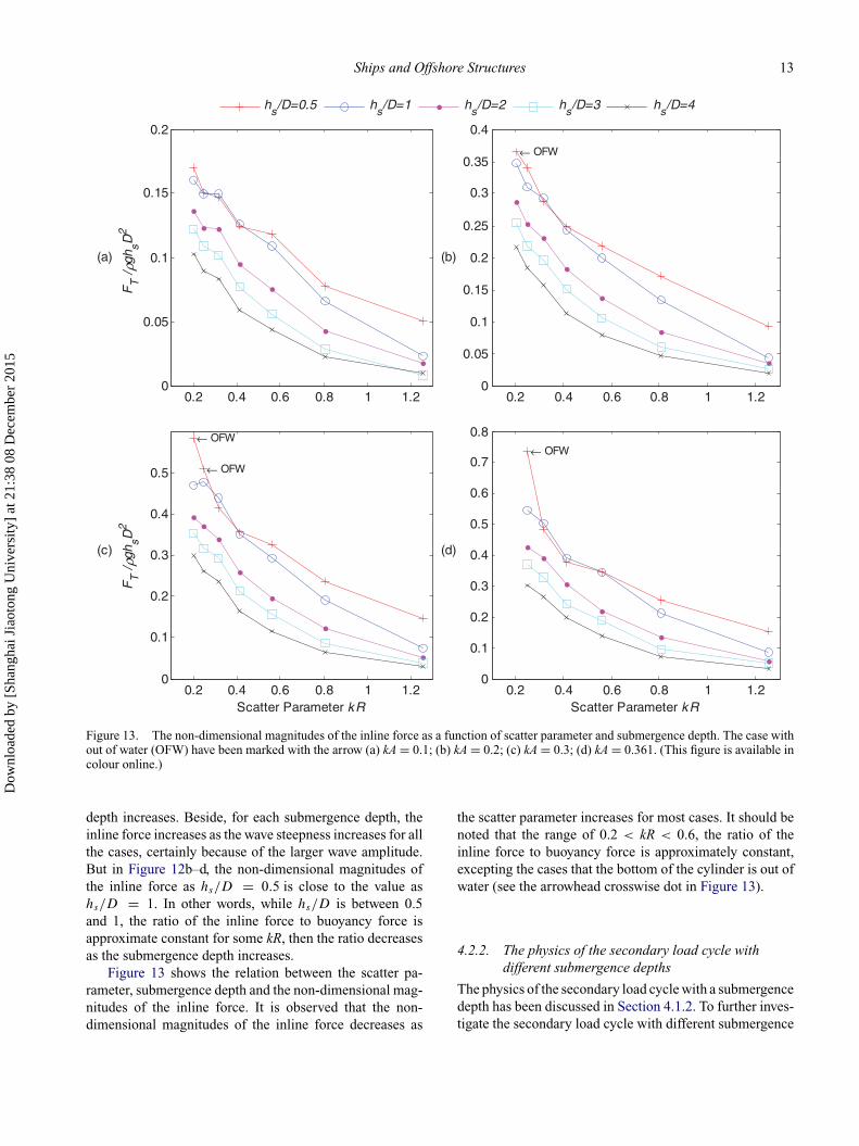
Figure 13. The non-dimensional magnitudes of the inline force as a function of scatter parameter and submergence depth. The case without of water (OFW) have been marked with the arrow (a) kA = 0.1; (b) kA = 0.2; (c) kA = 0.3; (d) kA = 0.361. (This figure is available incolour online.)
depth increases. Beside, for each submergence depth, theinline force increases as the wave steepness increases for allthe cases, certainly because of the larger wave amplitude.But in Figure 12b–d, the non-dimensional magnitudes ofthe inline force as hs/D = 0.5 is close to the value ashs/D = 1. In other words, while hs/D is between 0.5and 1, the ratio of the inline force to buoyancy force isapproximate constant for some kR, then the ratio decreasesas the submergence depth increases.
Figure 13 shows the relation between the scatter pa-rameter, submergence depth and the non-dimensional mag-nitudes of the inline force. It is observed that the non-dimensional magnitudes of the inline force decreases as
the scatter parameter increases for most cases. It should benoted that the range of 0.2 < kR < 0.6, the ratio of theinline force to buoyancy force is approximately constant,excepting the cases that the bottom of the cylinder is out ofwater (see the arrowhead crosswise dot in Figure 13).
4.2.2. The physics of the secondary load cycle withdifferent submergence depths
The physics of the secondary load cycle with a submergencedepth has been discussed in Section 4.1.2. To further inves-tigate the secondary load cycle with different submergence
Dow
nloa
ded
by [
Shan
ghai
Jia
oton
g U
nive
rsity
] at
21:
38 0
8 D
ecem
ber
2015
14 H. Xiong et al.
0 0.2 0.4 0.6 0.8 1-1.2
-0.8
-0.4
0
0.4
0.8
1.2
time t/T
Fx /
Fm
ax
0 0.2 0.4 0.6 0.8 1-1.2
-0.8
-0.4
0
0.4
0.8
1.2
ζ/ζ m
ax
hs /D=0.5
hs /D=1
hs /D=2
hs /D=3
hs /D=4
G4(downstream)G2(upstream)
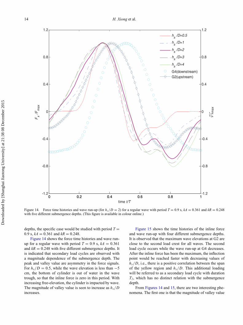
Figure 14. Force time histories and wave run-up (for hs/D = 2) for a regular wave with period T = 0.9 s, kA = 0.361 and kR = 0.248with five different submergence depths. (This figure is available in colour online.)
depths, the specific case would be studied with period T =0.9 s, kA = 0.361 and kR = 0.248.
Figure 14 shows the force time histories and wave run-up for a regular wave with period T = 0.9 s, kA = 0.361and kR = 0.248 with five different submergence depths. Itis indicated that secondary load cycles are observed witha magnitude dependence of the submergence depth. Thepeak and valley value are asymmetry in the force signals.For hs/D = 0.5, while the wave elevation is less than −5cm, the bottom of cylinder is out of water in the wavetrough, so that the inline force is zero in this period. Withincreasing free-elevation, the cylinder is impacted by wave.The magnitude of valley value is seen to increase as hs/D
increases.
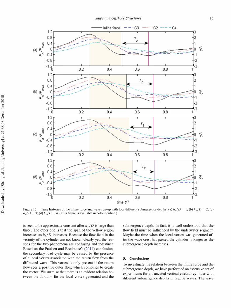
Figure 15 shows the time histories of the inline forceand wave run-up with four different submergence depths.It is observed that the maximum wave elevations at G2 areclose to the second load crest for all waves. The secondload cycle occurs while the wave run-up at G4 decreases.After the inline force has been the maximum, the inflectionpoint would be reached faster with decreasing values ofhs/D, i.e., there is a positive correlation between the spanof the yellow region and hs/D. This additional loadingwill be referred to as a secondary load cycle with durationT2, which has no distinct relation with the submergencedepth.
From Figures 14 and 15, there are two interesting phe-nomena. The first one is that the magnitude of valley value
Dow
nloa
ded
by [
Shan
ghai
Jia
oton
g U
nive
rsity
] at
21:
38 0
8 D
ecem
ber
2015
Ships and Offshore Structures 15
Figure 15. Time histories of the inline force and wave run-up with four different submergence depths: (a) hs/D = 1; (b) hs/D = 2; (c)hs/D = 3; (d) hs/D = 4. (This figure is available in colour online.)
is seen to be approximate constant after hs/D is large thanthree. The other one is that the span of the yellow regionincreases as hs/D increases. Because the flow field in thevicinity of the cylinder are not known clearly yet, the rea-sons for the two phenomena are confusing and indistinct.Based on the Paulsen and Bredmose’s (2014) conclusion,the secondary load cycle may be caused by the presenceof a local vortex associated with the return flow from thediffracted wave. This vortex is only present if the returnflow sees a positive outer flow, which combines to createthe vortex. We surmise that there is an evident relation be-tween the duration for the local vortex generated and the
submergence depth. In fact, it is well-understood that theflow field must be influenced by the underwater segment.Maybe the time when the local vortex was generated af-ter the wave crest has passed the cylinder is longer as thesubmergence depth increases.
5. Conclusions
To investigate the relation between the inline force and thesubmergence depth, we have performed an extensive set ofexperiments for a truncated vertical circular cylinder withdifferent submergence depths in regular waves. The wave
Dow
nloa
ded
by [
Shan
ghai
Jia
oton
g U
nive
rsity
] at
21:
38 0
8 D
ecem
ber
2015
16 H. Xiong et al.
force acting on a stiffly mounted cylinder and the secondloads cycle are both measured. The measured wave eleva-tion has been compared with the theoretical solutions forvalidation of the regular waves, while the wave forces havebeen also compared with the analytical solutions. The non-dimensional magnitudes of the inline force are computedto investigate the relation between wave force and its influ-encing factor. Some conclusions are drawn as follows:
(1) For each cylinder, the results clearly showed that thenon-dimensional magnitudes of the inline force de-creases when the incident-wave steepness decreasesor scatter parameter increases;
(2) The temporal development of second loads cyclewas shown to be dependent on the incident-wavesteepness and scatter parameter. The magnitude ofthe secondary load cycles was further shown toincrease in the long-wave regime and for the steeperwave;
(3) The non-dimensional magnitudes of the inline forcedecreases when the submergence depth or scatterparameter increases. The condition is that the ratioof the inline force to buoyancy force is approxi-mately constant while hs/D is between 0.5 and 1and kR is between 0.2 and 0.6;
(4) For the second loads cycle, the magnitude of valleyvalue is approximately constant after hs /D is largethan 3. The inflection point of the inline force wouldbe reached faster as hs/D decreases after the inlineforce has been the maximum.
It is noted that the present study have focused on the in-line force and wave elevations around the cylinder. In orderto understand the influences of submerged depth further,investigations on the flow field under the water surface arerequired.
AcknowledgementsThis work was financially supported by Shanghai Yang Fan Pro-gram (Grant no. 15YF1406100) and National Natural ScienceFoundation of China (Grant no. 51239007). The authors wouldlike to thank Mr. Huixiang Rong, Mr. Yanfei Deng and Mr. LeiGuan for their assistance on the test installations.
Disclosure statementNo potential conflict of interest was reported by the authors.
FundingShanghai Yang Fan Program [grant number 15YF1406100];National Natural Science Foundation of China [grant number51239007].
ReferencesAbbasnia A, Ghiasi M. 2014. A fully nonlinear wave interaction
with an array of submerged cylinders by NURBS numericalwave tank and acceleration potential. Ships Offshore Struct.9(4):404–417.
Abul-Azm AG, Williams A. 1988. Second-order diffraction loadson truncated cylinders. J Waterw Port C-ASCE. 114(4):436–454.
Deng Y, Yang J, Tian X, Li X. 2015. Experimental investigationon rogue waves and their impacts on a vertical cylinder usingthe Peregrine breather model. Ships Offshore Struct. 1–9.
Faltinsen O, Newman J, Vinje T. 1995. Nonlinear wave loads ona slender vertical cylinder. J Fluid Mech. 289:179–199.
Ferrant P. 1998. Fully nonlinear interactions of long-crested wavepackets with a three dimensional body. In: 22nd Symposiumin Naval Hydrodynamics; 1998 Aug. 9–14; Washington, DC:National Academies Press; p. 403–415.
Grue J, Huseby M. 2002. Higher-harmonic wave forces andringing of vertical cylinders. Appl Ocean Res. 24(4):203–214.
Huseby M, Grue J. 2000. An experimental investigation of higher-harmonic wave forces on a vertical cylinder. J Fluid Mech.414:75–103.
Malenica S, Molin B. 1995. Third-harmonic wave diffraction bya vertical cylinder. J Fluid Mech. 302:203–229.
Mccamy RC, Fuchs RA. 1954. Wave forces on piles: a diffractiontheory. No.TM-69. Corps of engineers Washington DC beacherosion board.
Molin B. 1979. Second-order diffraction loads upon three dimen-sional bodies. Appl Ocean Res. 1:197–202.
Newman J. 1996a. Nonlinear scattering of long waves by a ver-tical cylinder. In: Grue, Gjevik, Weber, editors. Waves andnonlinear processes in hydrodynamics. Springer Netherlands:Kluwer Academic Publishers; p. 91–102.
Newman J. 1996b. The second-order wave force on a verticalcylinder. J Fluid Mech. 320:417–443
Niedzwecki J, Duggal A. 1992. Wave run-up and forces on cylin-ders in regular and random waves. J Waterw Port C-ASCE.118(6):615–634.
Paulsen B, Bredmose H. 2014. Forcing of a bottom-mounted cir-cular cylinder by steep regular water waves at finite depth. JFluid Mech. 755:1–34.
Rainey R. 2007. Weak or strong nonlinearity: the vital issue. J EngMath. 58:229–249.
Yilmaz O, Incecik A. 1998. Analytical solution of the diffractionproblem of a group of truncated vertical cylinders. Ocean Eng.25(6):385–394.
Dow
nloa
ded
by [
Shan
ghai
Jia
oton
g U
nive
rsity
] at
21:
38 0
8 D
ecem
ber
2015