an experimental study on shear strength of flexural …€¦ · · 2017-05-16an experimental...
TRANSCRIPT

An Experimental Study on Shear Strength of
Flexural Member Using 3-side Inclined
Contineous Stirrups
Narendran.M
Department of Civil Engineering
P.S.R. Engineering College,
Sivakasi, India
Ramar.G
Department of Civil Engineering
P.S.R. Engineering College,
Sivakasi, India
Nishanth.M
Assistant professor
Department of civil Engineering
P.S.R. Engineering college
Sivakasi,India
Abstract— A beam is a horizontal flexural
member which provides support to the slab and vertical
walls. A normal beam(simply supported) consist of two
zones generally arise, compression zone at top and
tension zone at bottom. Our aim is to reduce the shear
failure of the structure and reduction in cost and time
for make a stirrup without losing its strength and
serviceability in the structural design. In this paper, an
experimental Study on shear strength arrested concrete
has been done to create reduction in shear crack and
savings in materials. Hence we are comparing a 3-side
inclined reinforced Stirrups(RC-3S) with a reinforced
concrete Conventional beam (RC-CB) in terms of
flexural strength. The beam is investigated in terms of
crack load and deflection curves.
Keywords— 3S(3-Side inclined stirrups), flexural
strength, deflection, beam, compression zone, tension
zone
I. INTRODUCTION
A beam is a structural element that primarily resists
load applied laterally to the beam’s axis. Its mode of
deflection is primarily by bending. The loads applied
to the beam results in reaction forces at the beam’s
support points. The total effect of all the forces acting
on the beam is produce shear forces, bending
moments and deflections of the beam. Beams are
characterized by their manner of supports, profile
(shape of cross-section), length and their materials
Beams must also have an adequate safety margin
against some type of failures such as shear, which
may be more dangerous than flexural failure. The
shear forces create additional tensile stress that must
be considered. Shear failure of reinforced concrete
beam, more properly called diagonal tension failure
is difficult to predict accurately. In spite of many
years of experimental research and the use of highly
sophisticated computational tools, it is not fully
understood. If a beam without properly designed for
shear reinforcement is overloaded to failure, shear
collapse is likely to occur suddenly. With no shear
reinforcement provided the member failed
immediately. So shear reinforcement should be
provided to resist these shears which created on the
beam. A flexural member designed to carry uniform
or concentrated line loads. A beam may act as a
primary member in beam-column frames, or may be
used to support slabs. A beam is a structural element
that is capable of withstanding load primarily by
resisting against bending. The bending force induced
into the material of the beam as a result of the
external loads, own weight, span and external
reactions to these loads is called a bending moment. It
is equal or slightly larger than the failure stress in
tension. Flexural strength, also known as modulus of
rupture, or bend strength, or transverse rupture
strength is a material property, defined as the stress in
a material just before it yields in a flexure test.
Stirrups are a reinforcement, that are provide to resist
the shear which induced on beams. The use of
stirrups is needed to prevent the columns and beams
form buckling. Stirrups are sometimes placed
diagonally and often vertically as well. This is done
to prevent shear failure which is usually diagonal in
case of cracks in beams. The primary reason for the
diagonal shear is due to compression and tension

caused by transverse and vertical tension. Eventually
diagonal tension occurs since concrete is stronger in
compression as compared to tension. This tension is
bound by steel stirrup which holds the cracked
surface together. The spacing of the stirrup along the
beam is important and should ideally be specified by
the designer. This will help the stirrups to be
manufactured accordingly. They are usually placed in
places where there are high chances of shearing such
as beneath large load and bearing points. Concrete is
made strong by running bars of steel through them.
However, stirrups are used to keep everything in a
straight line. Stirrups help keep order and also add
strength to the structure at critical points of probable
vulnerability from use over time. Steel rebar are
stronger than stirrups. However, often it is seen that
stirrups are used along with rebar. While rebar act as
the bones of the concrete, the stirrups aid the rebar to
remain straight and provide enhanced backing to the
column of concrete inside which it is placed. Stirrups
help secure much needed resistance. When the
pressure from above comes down on the column, the
stirrups act like tendons. They help the rebar and
concrete provide sustainable support for the extreme
amounts of load. Stirrups are an essentially high
strength steel wire which helps the concrete columns
just as the windows are held together by metal wires.
2. LITERATURE SURVEY
This Experimental study was conducted
on RCC beams to investigate the strength and shear
resisting capacity of various shear reinforcements
such as traditional shear reinforcements, inclined
shear reinforcements, combination of vertical and
inclined shear reinforcements and vertical shear
reinforcements with inclined cross bracings. The
various parameters like load deflection
characteristics, strength characteristics, shear cracks
and failure mode of concrete were investigated. It
was found that the shear reinforcement configuration
influence the strength characteristics of the beam.
This literature state that there was an improvement in
the shear resistance and stiffness was observed in
inclined stirrup system in comparison with traditional
stirrup system.
This paper presents an experimental investigation
to clarify shear cracking behavior of reinforced
concrete beams. The effects of the various influential
parameters on the spacing between shear cracks and
the relationship between shear crack width and stirrup
strain at the intersection with shear cracks were
carefully investigated. It was found that the shear
crack width proportionally increases with both the
strain of shear reinforcement and with the spacing
between shear cracks.
This paper explains that the shear failure of
reinforced concrete beam is often sudden and
catastrophic. This sudden failure, due to, shear, made
it necessary to explore more effective ways to design
reinforced concrete beam for shear. The reinforced
concrete beam show different behavior at the failure
stage in shear compare to bending, which is
considered to be unsafe mode of failure. The shear
cracks progressive rapidly without sufficient
advanced warning, and the diagonal cracks that
develop due to excess shear forces are considerably
wider than the flexural cracks. The cost and safety of
shear reinforcement in reinforced concrete beams led
to study of other alternatives. Bent-up bars have been
used in the past. New form of bent-up bars will be
used. Cross bars will be welded to these bent-up bars
making rectangles capable of resisting shear in a
plane compare to single bar performance. The main
purpose is to identify the most efficient shape to carry
shear forces at the lower cost. Several reinforced
concrete beams were carefully prepared and tested in
the lab. This literature explains the deflection of each
beam is measure at applied load. The propagation of
shear cracks was also closely monitored. This
literature explains the shear cracking behavior in
reinforced concrete beams with shear reinforcement
clearly.
This paper explains test results of six large-
size concrete beams reinforced with either
conventional- or high-strength steel and tested up to
failure. The beams were constructed without web
reinforcement to evaluate the nominal shear strength
provided by the concrete. The shear behavior,
ultimate load-carrying capacity, and mode of failure
are presented. The applicability of the current ACI
design code to large-size concrete beams constructed
without web reinforcement is discussed. The
influence of the shear span depth ratio, concrete
compressive strength, as well as the type and the
amount of longitudinal steel reinforcement is
investigated. The study shows that using high-
strength steel alters the mode of failure from diagonal
tension to shear compression failure and results in
higher shear strength compared with using
conventional steel. It was also found that the current
ACI shear design provisions are unconservative for
large-size concrete beams without web reinforcement.
This literature clearly explains the shear behavior of
large concrete beams that reinforced with high
strength steel.
The shear transfer mechanism greatly depends
on the diagonal compressive field in case of such
loading condition, so concrete would be significant in
the shear resistance. The past proposed equations of
shear strength of reinforced concrete members are
derived from the test results in the above mentioned
loading condition. But there are member that are
subjected to shear with the diagonal tension like as
footing beams in high rise building, and the members
should be designed considering the shear transfer

mechanism depended on the diagonal tension field.
The experimental study was carried out to investigate
the shear behavior of such members. This literature
clearly explains the influence of the loading condition
in RC beams on the shear resistance and strength in
presented.
3. METHODS AND MATERIAL PROPERTIES
3.1 Methodology:
Mix design of M40 concrete was done with
various type of reinforced stirrups beam. The curing
was done for 7, 14 and 28 days, after that the
hardened tests of compressive, flexural and tensile
were made on specimens for the strength test.
Material Test Result
Cement
Specific gravity 3.15
Consistency 35%
Fineness 1.00g for
100g of
cement
Fine aggregate Specific gravity 2.61
Fineness modulus 0.592
Coarse
aggregate
Fineness modulus 0.45
Impact 18.2%
4. RESULTS AND DISCUSSION
Compressive strength is most important
property of the hardened concrete. The concrete
cubes were casted, cured and tested accordance with
the IS standard and 7 & 28 days. Compressive
strength result of concrete are listed in Table4.1. The
highest compressive strength value is 42.08 N/mm2
which is obtained at 28 days
Table 4.1Compressive Strength
SPECIMEN 7 DAYS
(N/mm2)
28 DAYS
(N/mm2)
CONVENSIONAL 27.26 42.08
4.2 Flexural Test for beam:
The flexural test were carried at 28 days beam
4.2.1 Flexural Test for Conventional beam:
Load cell = 0
Channel (LVDT) = 9
SI.NO LOAD(kN) Deflecion (mm)
1 5.8 0.2
2 30.3 2.6
3 36.8 5.1
4 63.4 15.0
0
10
20
30
40
50
60
70
RC CON
Flexural strength on RC Conventional beam
LOAD (kN) DEFLECTION (mm)
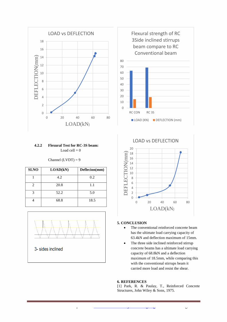
4.2.2 Flexural Test for RC-3S beam:
Load cell = 0
Channel (LVDT) = 9
SI.NO LOAD(kN) Deflecion(mm)
1 4.2 0.2
2 20.8 1.1
3 52.2 5.0
4 68.8 18.5
5. CONCLUSION
The conventional reinforced concrete beam
has the ultimate load carrying capacity of
63.4kN and deflection maximum of 15mm.
The three side inclined reinforced stirrup
concrete beams has a ultimate load carrying
capacity of 68.8kN and a deflection
maximum of 18.5mm, while comparing this
with the conventional stirrups beam it
carried more load and resist the shear.
6. REFERENCES
[1] Park, R. & Paulay, T., Reinforced Concrete
Structures, John Wiley & Sons, 1975.
0
2
4
6
8
10
12
14
16
18
0 20 40 60 80
DE
FL
EC
TIO
N(m
m)
LOAD(kN)
LOAD vs DEFLECTION
0
10
20
30
40
50
60
70
80
RC CON RC 3S
Flexural strength of RC 3Side inclined stirrups beam compare to RC Conventional beam
LOAD (KN) DEFLECTION (mm)
0
2
4
6
8
10
12
14
16
18
20
0 20 40 60 80
DE
FL
EC
TIO
N(m
m)
LOAD(kN)
LOAD vs DEFLECTION

[2] Saatcioglu, M. & Razvi, S., Strength and ductility
of confined concrete, Structural Engineering, ASCE,
118(25), pp. 1590-1607, 1992.
[3] Sheik, S. & Toclucu, M., Reinforced concrete
columns confined by circular spirals and hoops, ACI
Structural, 90(5), pp. 542-553, 1993.
[4] Hellenic Aseismic Code 2000 (in Greek).
[5] Essawy, A.S. & El-Hawary, M., Strength and
Ductility of Spirally Reinforced Rectangular
Concrete Columns, Construction and Building
Materials, 12(1), pp. 31-37, 1998.
[6] Karayannis, C.G., Sirkelis, G.M., Chalioris C.E.
& Mavroidis, P.D., External RC Joints with
continuous spiral reinforcement - Experimental
investigation, Proc. of 14th Greek Concrete Conf.,
Vol. A, (in Greek), Kos,Greece, pp. 343-353, 2003.
[7] Karayannis, C.G. & Sirkelis, G.M., Response of
columns and joints with spiral shear reinforcement,
Proc. of 12th Int. Conf. on Computational Methods
and Experimenta Measurements (CMEM 2005),
Malta, 2005.
[8] Karayannis, C.G. & Chalioris, C.E., Experimental
Investigation of the Contribution of Bonded C-FRP
jackets to Shear Capacity of RC Beams, Proc. of the
Int. Symposia Celebrating Concrete: People and
Practice, Vol. Role of Concrete in Sustainable
Development, Dundee, Scotland, UK, pp. 689-696,
2003.
[9] ASS Shahul Hameed M., Sekar, V Saraswathy
Arabian Journal for Science and Engineering volume
37 , issue 3, pages 561-574 Strength and permeability
characteristics atudy of self-compacting concret using
crusher rock dust and marble sludge powder. s
[10] Zararis P.D., Concrete Shear Failure in
Reinforced Concrete Elements, Structural
Engineering, ASCE, 122(9), pp. 1006-1015, 1996.
[11] S HAMEED M. Self concrete high performance
green concrete for sustainable development 1 2009
National conference on “Recent advancements in
construction materials