an experimental analysis of cutting quality in plasma arc
TRANSCRIPT

ADVANCED TECHNOLOGIES AND MATERIALS VOL. 45, NO. 1 (2020)
DOI: 10.24867/ATM-2020-1-001
ADVANCED TECHNOLOGIES & MATERIALS
http://journal-atm.org
* Corresponding author's.e-mail: [email protected] Received: 1 June 2020; Accepted: 25 June 2020
ATMJ O U R N A L
An Experimental Analysis of Cutting Quality in Plasma Arc Machining
Marin Gostimirović*, Dragan Rodić, Milenko Sekulić, Andjelko Aleksić
University of Novi Sad, Faculty of Technical Sciences, Department of Production Engineering, Trg D. Obradovica 6, 21000 Novi Sad, Serbia
A B S T R A C T
Plasma arc cutting (PAC) is an unconventional process widely used in manufacturing of heavy plate products. This work reports on the research results of machining quality of the workpiece in the plasma arc cutting on the low carbon low alloy steel. An experimental investigation of the characteristics of machining accuracy and surface integrity was carried out for basic machining parameters (cutting speed, arc current, arc voltage, plasma gas pressure, stand-off distance and nozzle diameter). The kerf geometry was determined with three accuracy parameters (top kerf width, bottom kerf width and kerf taper angle). The parameters of deviation present due to plasma curvature were defined by drag and pitch of drag line. The surface roughness was determined with two main roughness parameters through scanning the surface topography (roughness average and maximum height of the profile). The surface properties were determined over microstructure in heat affected zone (HAZ). The results show an acceptable machining quality of the PAC, so that this process is an excellent choice for fast and efficient material removal. However, the plasma arc cutting is not suitable for the final machining because of the metallurgical variations in the HAZ.
Key words: plasma arc cutting; machining accuracy; surface topography; heat affected zone
1. INTRODUCTION
Modern industrial production is characterized by the need to satisfy consumers in terms of range, quality, prices and delivery times of products or services. This means that just attractive products and services can survive on the global market, which provides consumers with more than expected. In this context, the industrial systems of the future must be able to adapt to the demands of the market. In the manufacturing industries, cutting process is one of the first stages in production of a particular component or product [1-3]. The cutting process entails the use of different techniques. The choice of technique depends on the type of material to be cut, as well as size, shape and the required level of precision of the worked part. There are two basic cutting methods in use. Examples of classic cutting techniques are the use of sawing and flame cutting [4]. Sawing is a mechanical cutting process of workpiece with circular and band sawing machines. This method is used for smaller sections and more precise cutting operation, but it is very
slow production method. On the other hand, Flame Cutting (FC) is oxy-fuel gas cutting thermal process which is used during the hard and rough work. Depending on the application, this method is often the preferred process because it’s much faster than mechanical machining. The flame cutting also is very portable and has low equipment costs. However, due to the flame heat, the edges being cut can often form a highly defective surface layer [5], known as a heat affected zone (HAZ). In recent times, modern manufacturing largely conducts cutting operations which are supported by unconventional technologies. These processes are defined as a group of cutting methods that remove the material by various non-traditional techniques, not using direct contact between the tool and the workpiece. Examples of unconventional cutting methods are the use of water jet cutting, laser beam cutting and plasma arc cutting. The main advantages of unconventional technologies material cutting processes are quality cuts and cost effective with the ability to cope with different types materials and geometrical configurations.

ADVANCED TECHNOLOGIES AND MATERIALS VOL. 45, NO. 1 (2020)
2
Water Jet Cutting (WJC) is a mechanical process, with or without abrasive particles [6]. This process uses a high-power kinetic energy of the water flow to the cutting of the workpiece material. The process produces a precise cut on all types of materials (metal, stone, glass, plastic, composites, ceramic etc.), but is especially suitable for the cutting of very hard and difficult-to-machine materials with complex contours. In the WJC process there is no change in mechanical and morphological properties of the workpiece material. Therefore, this process is especially appropriate for heat sensitive materials, because there is no heat affected zone. A significant advantage of water jet cutting is environmental aspect, since it does not create hazardous waste in the form of dust or gas. Basic disadvantage of water jet cutting is long processing time. Laser Beam Cutting (LBC) is a thermal process involving photon energy as a heat source [7]. The high light energy is focusing on the surface of the workpiece, which is then heating, melting and vaporizing. This process removes almost all metallic or non-metallic material. The LBC process is best suited for sheet cutting, complex profile cutting, brittle materials machining and drilling and perforating very small holes. The laser cutting doesn't take long and has a high level of efficiency and accuracy. In case of laser beam cutting, the heat affected zone and deformation in the part are very small. Disadvantages of the LBC are high energy consumption and maintenance cost, the gases released during the process can be toxic and reflective metals can't be cut using this technology. Plasma Arc Cutting (PAC) is a thermal non-traditional material removal process [8-10]. The PAC process uses a focused jet of high velocity and temperature ionized gas to melt, vaporize and remove material from the workpiece. The plasma arc cutting is the most common materials cutting technique for larger and more demanding plates, profiles and pipes. Advantages of plasma arc cutting are that any metal can be cut, process offers fast cutting speeds, slag-free cuts and operation with more burners. Disadvantages of the PAC process are low quality cut and a slightly wider kerf, relatively high power and gas consumption as well as generation of smoke and noise during process. The basic cutting techniques and their machining characteristics are illustrated in Fig. 1. In this work is presented investigation of the plasma arc cutting from the standpoint machining characteristics of the process. It is known that plasma arc cutting offers very high productivity but low cut quality. In order to enhance the cutting quality of PAC, since its commercialization, researchers are constantly examining ways to improve this process. Pawar and Inamdar [11] systematized the parameters affecting quality of plasma arc cutting from the standpoint of dimensional accuracy and surface quality without any further operations. The paper highlights recent results obtained by using plasma cutting process based on experiments and various methods that have been used for optimisation of PAC process.
Fig. 1 The review of the basic cutting techniques
Salonitis and Vatousianos [12] conducted an experimental research of the plasma arc cutting for assessing the quality of the cut. The cutting quality has been monitored by measuring the kerf width, kerf taper angle, surface roughness and heat affected zone. The quality characteristics were assessed by varying the processing parameters, such as the cutting speed, workpiece thickness, plasma power and gas pressure. Gariboldi and Previtali [13] conducted experiment to improve the cutting quality performed by high tolerance plasma arc cutting. The experiment was investigated under different process conditions like using several cutting speed with the adoption of oxygen or nitrogen as working and shielding gases. They found that if oxygen was used as the plasma gas, a higher cutting speed and better quality of kerf geometry parameters were achieved due to the oxidation reaction. Bini, Colosimo, Kutlu and Monno [14] revealed that cutting speed and arc voltage affect the kerf geometry formation mechanism. They also concluded that waviness can be reduced by reducing the cutting speed. Radovanovic and Madic [15] modeled plasma arc cutting process using artificial neural networking Using this model the cutting speed and arc current were selected which correspond to the cut with minimal surface roughness. Since it is still the main task of the plasma cutting to achieve the high productivity with as good quality as possible, in this paper special attention is directed on the effect of machining conditions on the accuracy and change of surface integrity. If the machining conditions are poorly chosen, it can substantially diminish exploitation features of the plasma arc cutting. Therefore, in order to enable machining with a high performance, it is necessary to investigate the effect of the PAC process on the cut quality of the workpiece. Specifically, in this paper specifics of the plasma arc cutting were experimentally investigated and their influence on material removal rate, surface topography, heat affected zone and kerf geometry accuracy.
2. PLASMA ARC MACHINING
Plasma Arc Machining (PAM) is one of the relatively recent nonconventional manufacturing processes. This

ADVANCED TECHNOLOGIES AND MATERIALS VOL. 45, NO. 1 (2020)
3
technique was patented by R. Gate in 1957. Initially it was used for cutting difficult-to-machine materials and later its application was extended to a large number of other production operations that require high concentrations of thermal energy: welding, sintering, coating, depositing, heat treatment, etc [16, 17]. In physics, the term plasma describes a gas state of matter which has been heated to a sufficiently high temperature to become partially or completely ionized gas. Thereby, ionized gas represents a mixture of positive and negative ions, as well as neutral free electrons, atoms, molecules, photons and radicals. Because of the high density of ions and electrons, plasma is highly electrically conductive. Temperatures in the plasma range from 10,000 to 30,000 °C.
2.1 Working principle of PAM process
The plasma arc machining is based on the high thermal and kinetic energy of ionized gas, directed to the surface of the workpiece. These energies lead to the development of a very high temperature in the region of plasma impact on the material. The temperature at the machining zone reaches the value of 4,000 to 10,000 °C. Such a high temperature causes intense melting and vaporizing (combustion) of any type of workpiece material. Afterwards, the molten material together with the eroded particles is removed by the explosive activity of the internal dynamic forces of the plasma channel, as well as by a fast jet of the plasma source. Thereby, an extremely high concentration of thermal energy leads to a number of physical-chemical processes and phenomena in the wider area of the workpiece surface. How the hot gas intensively comes out of a nozzle, there is a chance of overheating of plasma torch. A water flow is used to surround the plasma torch to avoid its overheating. For the process of plasma arc machining, the mechanism of the ionization of working gas is mainly realized by heating the gas to a very high temperature, as a result of which ionized gas is formed. This type of ionization involves the passage under pressure of a mixture of gases (working and shielding gas) through the space between the anode and the cathode, where, with power supply (DC) a strong electric arc is maintained. In the result of this is formed an ionized gas flowing from the nozzle in the form of a high heat plasma. The working gases used to create plasma are argon, helium, nitrogen, carbon dioxide or air, as well as a mixture of these gases. Hydrogen or oxygen is used as a shielding gas in the PAM. The electric arc can be performed directly in a plasma torch between the electrodes (anode and cathode) or between the workpiece (anode) and the central electrode (cathode). The first variant can be used for processing all types of materials, but the intensity of the plasma is slightly lower. In the second variant large thermal energy is generated, which is important when machining difficult-to-machine materials of large thickness, but it is possible to process only electrically conductive materials. Shown in Fig. 2 is principle of PAM process, input parameters (workpiece, machine, plasma torch and
plasma gas) and output performance (productivity, accuracy and surface integrity).
Fig. 2 PAM process with machining characteristics
2.2 Quality of plasma cutting
Similar to other machining processes, productivity, accuracy and quality are the most important performance of plasma arc cutting. In that context, it is very important to have a good knowledge of the characteristics and properties of the PAC process to get the best performance. Basic characteristics of the PAC are: velocity of plasma jet; arc current, voltage and power; gas pressure and flow rate; and nozzle diameter and stand-off distance. The productivity of PAC process is expressed by the material removal rate and in this process it is defined as the machining speed. The accuracy is defined by the tolerances applied to the dimensions and form of the workpiece. The quality is expressed through the surface topography and surface properties. Thereby, the effectiveness of the machining process determines the productivity and the product functionality defines the accuracy and quality. The quality of a part is particularly significant characteristic of the plasma arc cutting. It is generally defined by the following properties: machining accuracy and surface integrity. Fig. 3 is showing the PAC process mechanism with the quality indicators. Machining accuracy is determined by the degree of concordance of the actual dimension and shape of the part with the nominal geometry. The plasma arc cutting accuracy is typically defined by kerf geometry (ISO 9013). The kerf geometry is normally expressed by top kerf width Kt, bottom kerf width Kb and kerf taper angle [7, 14]. Surface integrity is described by the properties of the workpiece material, above and below the surface, after being modified by machining or other surface generation process. The surface integrity refers to the external

ADVANCED TECHNOLOGIES AND MATERIALS VOL. 45, NO. 1 (2020)
4
topography aspects of the surface (surface morphology and texture surface) and the internal physical and mechanical metallurgy aspects of the subsurface (surface layer modification).
Fig. 3 Quality indicators of PAC process
The surface topography in plasma arc cutting is defined by micro-geometry deviation, surface roughness and waviness (ISO 4287). The micro-geometry deviation is present due to plasma curvature, and defined by drag n and pitch of drag line f. It is specificity of PAM mechanism, because during interaction with the material the plasma jet loses its kinetic energy and changes its shape. Full and straight cuts are transformed into curved,
deformed or unfinished [6]. The surface roughness is represented by different profile amplitude parameters. Roughness average Ra, which is the arithmetic average of the absolute values of the profile heights over the evaluation length ln, is the primary parameter of the surface roughness. Waviness is defined by surface irregularities on a larger scale than the roughness. It is determined by the waviness spacing Sw and waviness height Wt. The surface metallurgy in plasma arc cutting includes the properties of the material layer, respectively study of the nature of the microstructure, microhardness, residual stress, crack, burn, etc [5, 18]. The metallurgical characteristics of the material are caused by the thermal energy, and this is called the heat affected zone (HAZ).
3. EXPERIMENTAL SETUP
Experimental investigations were carried out on the 3-axis plasma arc cutting machine type CNC Omnicut 4000 by a manufacturer MGM from Czech Republic, Fig. 4/a. Main technical data of the PAC machine are as follows: table area 12000x3000 mm, working current 0 to 130 A, arc voltage 50 to 150 V, total power consumption 1.5 kVA max, cutting speed 20-30000 mm/min, max thickness of the cut sheet 200 mm, positioning accuracy 0.3 mm. This configuration provides excellent dynamic and static properties, high stiffness of the machine carriage, high cutting accuracy and high productivity.
Fig. 4 PAC machine (a) and RSt 37-2 steel plate after cutting (b)
In the paper, first the basic experimental tests were carried out to assess the quality indicators for a reference level of process parameters in plasma arc cutting. The reference level of parameters selected as representatives are: arc current I=80 A, arc voltage U=127 V, plasma gas pressure p=0.5 MPa, nozzle diameter d=1.75 mm, stand-off distance z=2 mm and impact angle =90. The range of the cutting speed was v=700 to 2500 mm/min. Water cooled nozzle and air plasma / air shield combination was
ADVANCED TECHNOLOGIES AND MATERIALS VOL. 45, NO. 1 (2020)
5
used for plasma cutting operation. Then, in the extended experiment some reference parameters were further varied. The arc current was chosen from the interval 50 to 100 A and the arc voltage in the interval 121 to 133 V. The plasma gas pressure was 0.5 and 0.7 MPa, the nozzle diameter was 1.5 and 1.75 mm and the stand-off distance was 1 to 3 mm. While a certain value was varied, the other values were held constant at the reference level. The basic work material used in the experiment was DIN RSt 37-2 carbon low alloy steel (0.17% C, 1.4 % Mn, 0.05% S, and 0.05% P), tensile strength Rm=420 MPa. RSt 37-2 is steel which contains ferrite and pearlite microstructure, where the ferrite is much higher with respect to the pearlite, Fig. 5. Thickness of the workpiece was 10 mm. The cut workpiece is shown in Fig. 4/b. The samples were cut by the PAC under certain machining conditions. First, the parameters of the kerf geometry (top kerf width Kt, bottom kerf width Kb and kerf taper angle ) were measured. Then, the parameters of the plasma jet deviation (drag n and pitch of drag line f) were measured. The measurements were conducted using digital caliper with accuracy to 0.001 mm, as well as by reading the values at the photo samples recorded using USB digital microscope with 200x magnification.
Fig. 5 Microstructure of workpiece material at magnification of 200x
Surface roughness of the workpiece in the PAC process was estimated by measuring a set of surface parameters. The measured parameters were roughness average Ra (arithmetic mean deviation of the profile) and maximum height of the profile Rt (vertical distance between the highest and lowest points of the profile). These parameters are the most widely used in surface roughness measurements. The surface roughness measurements were performed using the profilometer Mitutoyo SJ-301, Japan. Surface properties of the specimens were assessed by investigation of surface layer modification of the workpiece after the plasma arc cutting. In this testing a metallographic examination of the microstructure was implemented, i.e. the heat affected zone (HAZ) was evaluated. The surface metallographic identification of the workpiece was performed with an Olympus BHM/BH2 microscope with 1000× magnification from Japan. For metallographic preparation was used the equipment of the Struers, Denmark.
4. RESULTS AND ANALYSIS
4.1 Basic experiment
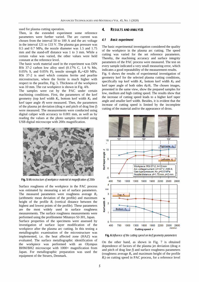
The basic experimental investigation considered the quality of the workpiece in the plasma arc cutting. The speed cutting was varied for the set reference parameters. Thereby, the machining accuracy and surface integrity parameters of the PAC process were measured. The test on every sample indicated a very small measuring error, which indicates a good repeatability of the measurement results. Fig. 6 shows the results of experimental investigation of geometry kerf for the selected plasma cutting conditions, specifically top kerf width Kt, bottom kerf width Kb and kerf taper angle of both sides R/L. The chosen images, presented in the same view, show the prepared samples for low, medium and high cutting speed. The results show that the increase of cutting speed leads to a higher kerf taper angle and smaller kerf width. Besides, it is evident that the increase of cutting speed is limited by the incomplete cutting of the material and/or the appearance of dross.
Fig. 6 Influence of the cutting speed on kerf geometry parameters
On the other hand, as shown in Fig. 7 is obtained dependence of factors of the plasma jet deviation (drag n and pitch of drag line f) and surface roughness parameters (roughness average Ra and maximum height of the profile Rt) on cutting speed in PAC process, for a reference level

ADVANCED TECHNOLOGIES AND MATERIALS VOL. 45, NO. 1 (2020)
6
of parameters. In the same figure, are shown the experiment samples for three characteristic cutting speeds. It can be seen that the values of the micro-geometry deviation and surface roughness are higher when the cutting speed increases. It is evident that the increase of the cutting speed leads to very poor surface topography and roughness.
Fig. 7 Influence of the cutting speed on plasma jet deviation
In this study, metallographic investigations of the surface properties of the material show that there are heat affected zone (HAZ) at all machining conditions of PAC. However, the metallographic examinations showed the uniform size of the HAZ during various cutting speeds. Fig. 8 shows a photomicrograph of the surface layer of the investigated RSt 37-2 carbon steel after the plasma arc cutting, i.e. its microstructure transformation compared to the bulk material. The analysis of the microstructure of material revealed three characteristic layers which are: the resolidified layer, the modified surface layer and the interlayer. The resolidified layer is a thin zone of the deposition of residual molten material on the surface. The modified layer consists of the ferrite-pearlite transformation to martensite. The interlayer shows gradual transition of modified layer into bulk material. It is noted that observed thickness of the total heat affected zone is in the range of about 1mm.
Fig. 8 Photomicrograph of surface layer of carbon steel cut by PAC at magnification of 100x
4.2 Extended experiment
In the extended experiment some additional tests were conducted in order to provide a more complete view of plasma arc cutting quality. The main reference parameters were further varied, namely, arc current, arc voltage, plasma gas pressure, stand-off distance and nozzle diameter. Thereby, only the macro geometrical parameters of quality were measured. The concept of deviation of the measured value from the nominal one is used for an evaluation of the accuracy of the kerf geometry. Delamination factor DF is the main geometric characteristic of the damages of the plasma arc cutting process. The delamination factor was defined as the ratio of top kerf width Kt to bottom kerf width Kb during the cutting of the workpiece material (DF=Kt/Kb). Fig. 9 shows the influence of the cutting speed on delamination factor for two arc currents in PAC process. The diagram shows that the increase of cutting speed results in increased delamination factor, especially at high speeds. Thereby, a larger arc current increases the delamination factor too.
Fig. 9 Dependence of the delamination factor on cutting speed
Shown in Figure 10 is obtained dependence of the delamination factor on arc voltage during two plasma gas pressure. The diagram shows that there exists an optimal

ADVANCED TECHNOLOGIES AND MATERIALS VOL. 45, NO. 1 (2020)
7
arc voltage which results in minimum delamination factor. It is also seen that the larger plasma gas pressure decreases the delamination factor.
Fig. 10 Influence of the arc voltage on delamination factor
Fig. 11 shows the influence of the arc current on delamination factor for two nozzle diameters. The diagram shows that the increase of arc current results in significantly reduced delamination factor, and this for both nozzle diameters. Thereby, a smaller nozzle diameter makes somewhat lower delamination factor.
Fig. 11 Dependence of the delamination factor on arc current
Shown in Figure 12 is obtained dependence of the delamination factor on nozzle stand-off distance during two cutting speeds. The diagram shows that there exists a slight increase of the delamination factor with increase of cutting speed. Of course, a lower cutting speed is more acceptable.
4.3 Discussion
Analysis of previous experimental results revealed that most impact on the plasma arc cutting quality has the cutting speed. Increase of the cutting speed increases the macro and micro geometrical parameters of quality (parameters of the kerf geometry, parameters of the plasma jet deviation and surface roughness parameters). Also, the arc current has a significant effect on the machining quality. On the other hand, the arc voltage, plasma gas pressure, stand-off distance and nozzle diameter have somewhat less impact on the quality.
Besides, the mentioned machining parameters have mostly the opposite effect on the quality, which significantly complicates control design of the plasma arc cutting process.
Fig. 12 Influence of the stand-off distance on delamination factor
At the same time, it is important to note that there is heat affected zone at any machining conditions of the plasma arc cutting. The thickness of the HAZ is related to machining conditions, but above all with the material thickness and its thermal conductivity. Thereby, influence of PAC machining parameters on the HAZ is almost identical. As previously mentioned, it is evident that the machining quality in PAC process depends on a number of machining parameters. Figure 13 shows the level of variation of the most important parameters of the quality, i.e. degree of their effect on the PAC process. The level of variation of the plasma arc cutting parameter was determined by using advanced statistical analysis.
Fig. 13 The level of variation of the machining parameters on the quality of PAC process
5. CONCLUSIONS
Plasma arc cutting is a non-traditional highly productive process widely used in plate processing made from difficult-to-machine materials. Compared to other cutting techniques, the PAC process achieves the fastest cutting speed with satisfactory accuracy and surface finish. However, the plasma arc cutting leads to intense concentration of heat in the cutting area, which is why heat affected zone is always present.

ADVANCED TECHNOLOGIES AND MATERIALS VOL. 45, NO. 1 (2020)
8
On the ground of experimentally measured values it can be concluded that increasing of the cutting speed and arc current leads to a significant deterioration of machining quality of the PAC process. It is primarily the cut geometry deviation, presence of the jet lag effect present due to plasma curvature, increase of the surface roughness and the occurrence of dross. However, the other machining parameters have different impact on the cutting quality, which additionally complicates setting and guidance of the plasma arc cutting process. The investigations show that there is a major heat affected zone at defined machining conditions in the PAC process. The heat affected zone is related to above all with the type and thickness of material. The value of the HAZ is greater for thicker non-conductive material that is cut at lower cutting speed and larger arc current.
ACKNOWLEDGEMENTS
This paper presents a part of researching at the Project financed by Ministry of Education, Science and Technological Development of the Republic of Serbia.
REFERENCES
[1] Kovac, P., Gostimirovic, M., Sekulic, M., Savkovic, B. (2009). A review of research related to advancing manufacturing technology. Journal of Production Engineering, 12(1), 9-16.
[2] Sekulic, M., Kovac, P., Gostimirovic, M., Kramar, D. (2013). Optimization of high-pressure jet assisted turning process by Taguchi method. Advances in Production Engineering & Management, 8(1), 5-12., DOI: 10.14743/apem2013.1.148.
[3] Patel, P., Nakum, B., Abhishek, K., Kumar, R. (2018). Machining performance optimization during plasma arc cutting of AISI D2 steel: application of FIS, nonlinear regression and JAYA optimization algorithm. Journal of the Brazilian Society of Mechanical Sciences and Engineering, 40, 240, DOI: 10.1007/s40430-018-1087-7.
[4] Zhou, B., Liu, Y. J., Tan, S. K. (2013). Efficient simulation of oxygen cutting using a composite heat source model. International Journal of Heat and Mass Transfer 57(1), 304–311.
[5] Gostimirovic, M., Kovac, P., Sekulic, M. (2018). An inverse optimal control problem in the electrical discharge machining. Sadhana, 43(5), 70, DOI: 10.1007/s12046-018-0844-8.
[6] Gostimirovic, M., Pucovsky, V., Sekulic, M., Rodic, D., Pejic, V. (2019). Evolutionary optimization of jet lag in the abrasive water jet machining. International Journal of Advanced Manufacturing Technology, 101(9–12), 3131-3141, DOI: 10.1007/s00170-018-3181-5.
[7] Madic, M., Radovanovic, M., Gostimirovic, M. (2015). ANN modeling of kerf taper angle in CO2 laser cutting and optimization of cutting parameters using Monte Carlo method. International Journal of Industrial Engineering Computations, 6(1), 33-42, DOI: 10.5267/j.ijiec.2014.9.003
[8] Singh, G., Akhai, S. (2015). Experimental study and optimisation of MRR in CNC plasma arc cutting. International Journal of Engineering Research and Applications 5(6), 96–99.
[9] Pawar, S. S., Inamdar, K. H. (2017). Experimental Analysis of Plasma Arc Cutting Process for SS 316 l Plates. IOSR Journal of Mechanical and Civil Engineering, 75-80.
[10] Naik, D. K., Maity, K. (2020). Experimental analysis of the effect of gas flow rate and nature on plasma arc cutting of hardox-400. Weld World 64, 345–352, DOI: 10.1007/s40194-019-00836-8.
[11] Pawar, S. S., Inamdar, K. H. (2016). Factors affecting quality of plasma arc cutting process: A review. International Journal of Advanced Technology in Engineering and Sciences, 4(12), 177–183.
[12] Salonitis, K., Vatousianos, S. (2012). Experimental investigation of the plasma arc cutting process. Procedia CIRP, 3(1), 287–292, DOI: 10.1016/j.procir.2012.07.050.
[13] Gariboldi, E., Previtali, B. (2005). High tolerance plasma arc cutting of commercially pure titanium. Journal of Materials Processing Technology, 160(1), 77–89.
[14] Bini, R., Colosimo, B. M., Kutlu, A. E., Monno, M. (2008). Experimental study of the features of the kerf generated by a 200A high tolerance plasma arc cutting system, Journal of Materials Processing Technology, 196(1-3), 345-355.
[15] Radovanovic, M., Madic, M. (2011). Modeling the plasma arc cutting process using ANN, Nonconventional technologies review, 4, 43–48.
[16] Hema, P., Ganesan, R. (2020). Experimental investigations on SS 304 alloy using plasma arc machining. SN Applied Sciences 2, 624, DOI: 10.1007/s42452-020-2350-y.
[17] Maity, K. P., Bagal, D. K. (2015). Effect of process parameters on cut quality of stainless steel of plasma arc cutting using hybrid approach. International Journal of Advanced Manufacturing Technology, 78(1–4), 161–175, DOI: 10.1007/s00170-014-6552-6.
[18] Gostimirovic, M., Sekulic, M., Kopac, J., Kovac, P. (2011). Optimal control of workpiece thermal state in creep-feed grinding using inverse heat conduction analysis, Strojniški vestnik - Journal of Mechanical Engineering, 57(10), 730-738, DOI: 10.5545/sv-jme.2010.075