an exact solution of the boundary-layer equations under...
TRANSCRIPT

R. & M. No. 22,tl (9656)
A.R.C. Technical Report
An
o '
MINISTRY OF SUPPLY
A E R O N A U T I C A L R E S E A R C H C O U N C I L R E P O R T S A N D M E M O R A N D A
1
, : : '3
t " . . . . Cj~
t ,% . . . . , Z~"
Exact Solution of the Boundary-layer Equations Under Particular Conditions
of Porous Surface Suction
B. THWAITES, B.A., of" the Aerodynamics Division, N.P.L.
Crowu Copyright Reserved
LONDON: HIS MAJESTY'S STATIONERY OFFICE
Price is. 3d. net

NATIONAL AERO~!AUT|CAL ESTAB~SH~JENT
An Exact Solution of the B6ii ¥ R,A~
ridary-layer Equations Under Particular Conditions of Porous Surface Suction
By
B. THWAITES, B.A.,
of the Aerodynamics Division, N . P . L .
Reports az'd Memoranda 1370. 2 2 4 I
M a y , I 946
S u m m a r y . - - N o hitherto successful attempts except one (by Griffith and Meredith ~) have been made to provide an exact solution of the boundary-layer equations of motion when there is a continuous normal velocity at the boundary. At the suggestion of Preston 2 a solution is given in this report when this suction velocity is proportional to x -11~, x being the distance along the plate, and there is a constant velocity outside the boundary layer. The solution is merely an extension of the well-known Blasius' solution, and does not contain any new mathematical technique. Being exact, however, it can command a certain interest, since the treatment of the boundary-layer equations with suction through the boundary is very difficult (Thwaites4).
The solutions of the differential equation below were obtained on the differential analyser, at Manchester University, at present on loan to the Mathematics Division, N.P.L. Acknowledgements are made to the Analyser Group of this Division for providing these solutions, and in particular to E. C. Lloyd, who was concerned in this particular problem.
Theory.--The equat ion of flow in the boundary layer is
Oct ~u 32¢~ ~ + v ~ = , ~ . . . . . . . . . . . . . . . . (2)
in the usual notat ion, when the velocity outside the boundary is constant and equal to U. The
au ~v equat ion of cont inui ty ~ + ~ = 0 allows the use of the s t ream function ~0 for which
u - - 8~0 v - - ~1° ~y ax
Using Blasius' well-known t ransformat ion ,
~fUYIL ( , , U x ) ' / y , " ,~ = ~ k ~ ) ~,, ~, =
in w h i c h / i s a function of ~ only, (2) becomes
f"' + ff" ---- 0, . . . . . . . . . . . . . . . . (2)
and u, v are given by
u = ½Uf' , v = ½ x ( d ' - f ) .
At the boundary, v = 0 and u =- 0, whence f ' (0) = 0.
The condit ion at infinity is u ---- U, w h e n c e f ' (oo) = 2.
)Mso at the boundary v = -- }(Uv/x)ll"f(O). (81515)

2
The ordinary Blasius profile is obtained by solving (2) with the conditions
f (0) = 0, f ' (0) = 0, f ' (oo) = 2.
If however we give f (0) a finite value, we obtain the solution when the velocity of suction is
l (Uv~l /~f (O) ' 2 \ X /
i.e. proportional to x -it2. The possibility of this and other exact solutions of a similar type was pointed out by Preston *.
Clearly there is a singularity at the origin and the exact solution will not have much physical significance near that point, but in any case the boundary-layer equations are not good approxi- mations to the full equations of motion near x = 0. We can expect, however, that tile solution will give a good representation of the physical flow at some distance from the origin.
The solutions of (2) were found on the differential analyser for the boundary conditions f ' (0) = O, f ' (oo) = 2 and f (0) = r, r taking the values 1, 2, 5, 10, 20 in turn. The suction velocity is vo - - ½ (Uv /x ) lj2 r, or is given by -- vo/U = R 2 ~j~ al, R.~ being the x Reynolds number, and a~ being a number signifying the strength of suction.
The velocity distributions inside the boundary layer for the values al = 0.5, 1, 2.5, 5 and 10 are drawn out in Fig. 1 and are tabulated in Table 1. a~ = 0 corresponds to the ordinary Blasius profile. It will be noticed that as the suction strength increases the velocity profiles become more convex and the width of the boundary layer decreases.
~*, the displacement thickness, can be evaluated as follows : - -
Therefore, ½ , ; ~ , = fo [1 - ½f' (7)3 d~.
To obtain the value of this integral from Table 1, we proceed as follows : - -
( U',)~,, O, - , , ~ / -"- fo [1 - g'(~)] a,7,
where ~ is the value of ~ at wh ich f ' (7) becomes greater than (say) 1.99. Hence
½ ,~,(w( ~ 8. = ~ - ½ If (~) - f (0)].
which is immediately evaluated from Table 1 for different values of a~. 0, the momentum thickness may be evaluated similarly. Figure 4 shows how $* and 0 vary with the amount of suction, and it shows that only a small amount of suction is required.to produce a large decrease of displacement thickness. On this figure H = ~*/0 is also shown.
It would be interesting to see the configuration of flow and we therefore wish to find ordinates of streamlines. The streamline ~ = k is given by
( , Ux)l~ f (~) = k . . . . . . . . . . . . . . . . (3)
Given k and al for a certain x, (3) determines f (~) and hence 7, and hence y. Values of f are given in Table i, and therefore the ordinates of streamlines are readily evaluable. Figure 2 shows some streamlines near x = 0 for a~ ---- 1, the mass-flow into the surface being equal between each pair of consecutive streamlines. This figure is not without interest, although it probably

{
3
bears little resemblance to the physical flow, as has been pointed out already. Also on Figure 2 is drawn the displacement thickness 8*. Figure 3 demonstrates the streamlines over a far greater length of the boundary and this configuration of streamlines is probably close to that in the real flow. The dotted curve in Figure 3 represents the boundary-layer thickness ~, which is defined by ½f' (6) = u/U = 0.995.
It is suggested that this theory would form the basis of an experiment suitable for a university laboratory. For a porous sheet of material, on each side of which is maintained a constant pressure, the velocity of fluid through it is proportional to I/t, t being the thickness of the sheet. Therefore the velocity through a sheet of parabolic form t = a~v/x is proportional to x -1/2, which is the suction velocity distribution considered in this report. The following sketch shows the arrangement which might be employed.
DIRECTION OF AIR STREAM
\ \ \ \ \ \ \ \ \ \ \ \ \ \ \ \ \ ~ / / / / / / / / / / / / / / / / / / / / / / / / / / / / / / / / / / / / / /
S U CT l 0 N C H A M B E R ~ " ~ L ' ~ L ~ L ~ / / / / / / / / / / / / /
The main feature of this arrangement is the maintenance of a fiat boundary, thereby avoiding the departure from uniformity of flow if the parabolic sheet were placed in the stream. The growth of a boundary layer along the surface upstream of the porous sheet might be avoided by moving this surface, made of pliable material, round rollers. This arrangement could also be used to test the Tollmien-Schlichting stability theory for different velocity profiles, obtainable by different amounts of suction.
No. Author
1 Griffith, A. A. and Meredith, F. W.
2 Preston, J. H . . . . . . .
3 Thwaites, B . . . . . . . . .
4 Thwaites, B . . . . . . . . . .
REFERENCES Title, etc.
The Possible Improvement in Aircraft Performance due to the use of Boundary-layer Suction. R.A.E. Report No. E.3501. A.R.C. 2315. March, 1936. (Unpublished.)
The Botmdary-layer Flow over a Permeable Surface, through which Suction is Applied. R. & M. 2244. February, 1946.
On the Flow Past a Flat Plate with Uniform Suction. A.R.C. 9391. February, 1946. (To be published.)
Investigations into the Effect of Continuous Suction on Laminar Boundary-layer Flow under Adverse Pressure Gradients. A.R.C. 9555. April, 1946. (To be published.

4
T A B L E 1
Solutions of f " + i f" = 0
f ' (0) = 0 f ' - + 2 as r / - + c o f (0) 231
0 O" 05 0-1 0 . 2 0 . 3 0"4
0 . 5 0 . 6 0 -7 0 -8 0 -9
1 .0 1"1 1.2 1"3 1"4
1"5 1"6 1.7 1-8 1 .9
2 -0 2 .1 2"2
a 1 = 0 . 5
if(O) I
0"141 0"286 0"537 0-751 0-953
1 '132 1"29 1"43 1"54 1"64
1-72 1-79 1-84 1"88 1-91
1 "94 1 "96 1 "97 1 "98 1 "99
1 "99 ! 1 . 9 9 2.00
f(~)
1.000 1.004 1-014 1.055 1.119 1.204
1"309 1.430 1"566 1-715 1-874
2"043 2 .219 2"400 2"584 2 '777
2 ' 970 3 '165 3"362 3.559 3.758
3.957 4-157 4.357
a l ~ - 1
/'(*J) /(,1)
0 2 .000 0.221 2.015 0.423 2-022 0.779 2-082 1.05 2-174 1-28 2-290
1.46 2.428 1.60 2.581 1.71 2.747 1.79 2 .922 1 '85 3" t05
1.90 3"293 1.93 3"484 1"95 3-679 1.97 3-875 1.98 4-073
1"99 4"272 1.99 4.471 2 .00 4.671
0 0-025 0"05 O' 075 0"1 0 .15
0 .2 0-25 0 -3 0 -4 0 . 5
0 .6 0 .7 0 . 8 0 .9 1.0
1.1 1 ' 2
al = 2 .5
f ' ( , )
o 1 0"243 i 0 " 4 6 9 , 0"650 0"813 1-09
1 "31 1 "47 1 "60 1" 77 1 "87
1 '93 1 "96 1 '98 1 '99 1 "99
1 "99 I
2 .00
f( ,)
5"000 5"003 5"018 5"026 5"044 5"092
5 '152 5"222 5"299 5"468 5"561
5-842 6"037 6"234 6"433 6"632
6 . 8 3 2 7. 032
0 0 '00625 0.0125 0"01875 0-025 0"0375
0"05 O" 0625 O" 075 O" 0875 0"1
0 '125 0 ' 1 5 0 ' 2 0 ' 2 5 0"3
0 .4 0 .5 0"6
a a = 5
f'(~)
I 0
O. 246
0 .457 0.631
0.795
1.07
1.28
I
1.57 1"74 1.85 1.91
1.97 1"99 2"00
f(v)
10-000
10-001
10.006 10.013
10'022
10"045
10.074
i0"146 10.229 10-320 10"414
10" 608 10" 807 11 "007
a 1 = 10
f ' (~) f(v)
0 20- 00¢ O" 234 20- 001 O. 443 20.003 O. 637 20.00(~ 0 .799 20.011 1.06 20- 022
I ' 27 20.037 1.43 20.054 1.56 20.07~ 1.65 20.09~ 1-73 20.114
1-84 20-15~ 1- 90 20-40~ 1- 96 20.30~ 1 "98 20.401 1' 99 20. 501
2" O0 20. 701

/ J
0 o .5 1,0 - ~7
FIG. 1.
2.0 2..~ 5.0
\ \ \ ~
i / FIG. 2,
(81515) B

6
tO0
/)
6O
50 t00 U ac
or , ' I I
- - - - - , . , . . . . . . ._
~; IE, O 7'00 7 5 0 5 0 0
1;IG. 3.
I.E,
0.5
/ - H
; ' -5
0 2 5 5"0
(81515) WL 11 5/4S Hw.
7.5
FIG. 4.
;0 .0 J2.5 15'0

A[ATIO~ AEROMI~"T'C~L ES~-ABLIBII~
LIBRAR
A Theoretical Discussion of High-lift Aerofoils with Leading-edge Porous Suction
By B. T~WAiT~S, B.A.
o f the A e r o d y n a m i c s Divis ion , N . P . L .
Reports and Memoranda No. 2242
1946
# 1949-, ......... t t -J ........ Y [ L113 I7A R
Summary.--It is shown in this report that by the principle of porous suction high lift coefficients can be obtained on thin aerofoils by the use of surprisingly small amounts of suction. It is more economical to use porous suction than to suck through a slot at or near the leading edge : and it is necessary to realise that in general the principles involved in the two types of suction are rather different. The discussion is restricted to aerofoils with rounded leading edges, since it is difficult to predict theoretically the effect of any type of suction on flow near a sharp edge.
There are given graphs showing estimates of the quantities of air to be sucked on three different typical thin sections to produce any reasonable desired lift coefficient. It seems that to obtain a lift coefficient of 2.0 on a 7 per cent. thick section on a fighter aircraft when landing, a quantity of air of 0.5 cu. ft./sec, per foot span is sufficient, to be sucked over the first 2 per cent. of the chord. Half this quantity of air sucked would suffice for a lift coefficient of 1.5. The design of the leading-edge shape is important but suitable aerofoils have already been designed in Ref. 1.
Introduction and Discussion.--As the speeds at wh ich aeroplanes fly increase, the th ickness of the i r aerofoil sect ions decrease, and the p rob l em of ob ta in ing a sufficiently high m a x i m u m CL also becomes more acute. Many m e t h o d s , mos t of t h e m well known, have been used to p roduce fair ly good max . CL's on sect ions of m o d e r a t e th ickness , say 15 per cent . , and these have na tu r a l l y been appl ied to t h i n n e r sections. However , it has now become desirable, if no t necessary, to devise r a the r new m e t h o d s of ob ta in ing h igh lift coefficients on th in wings, and f u r t h e r m o r e to avo id a n y large changes of t r i m t h a t m i g h t occur at t he same t ime. In this last respect , too grea t a use of flaps is undesi rable .
The p rob lem therefore reduces to t h a t of e x t e n d i n g the lift curve of an aerofoil pas t the usua l s ta l l ing poin t , which implies a p r even t ion of the separa t ion of flow from the nose of an aerofoil a t large incidences. There are three pr inc ipa l m e t h o d s of achieving this : (i) by sucking sufficient quan t i t i e s of air t h r o u g h the leading edge so t h a t t he whole ve loc i ty d i s t r ibu t ion over the aerofoil an d especial ly over its nose is a l te red in such a w a y as to de lay separa t ion , (ii) b y des igning the nose of the aerofoil so t h a t a t h igh incidences the usua l large adverse ve loc i ty g rad ien t is replaced b y a d i s con t inu i ty of veloci ty at a po in t w h e r e suc t ion is appl ied to p r e v e n t separa t ion , (iii) by us ing porous suc t ion over the nose, so t h a t the b o u n d a r y layer is k e p t th in and in good shape to overcome the adverse ve loc i ty gradients . Of these th ree me thods , t he second has been cons idered by Lighthi l l 2, who also uses a sort of combina t ion of m e t h o d s (i) and (ii). He derives aerofoils w i th sharp leading edges. I n this repor t , we shall on ly consider aerofoils wi th r o u n d e d leading edges, and it will be shown t h a t m e t h o d (iii) requires far smal ler a m o u n t s of suc t ion t h a n (ii) to produce high lift coefficients.
I. Potential Flow Considerations.--We shall examine the effect of a single suction slot, supposed concentrated at a point on the leading edge, upon the potential flow past an aerofoil. The aerofoil theory notation of Reference 3 will be used, with which the reader is assumed to be familiar.
(82249) A

Suppose tha t the symmetr ica l aerofoil has been conformallv t ransformed into the circle Z ---- Rd ~, so tha t the point Z = R corresponds to the leading edg).. I t is easy to verify tha t the velocity potent ia l due to a sink, of mass-flow m per uni t t ime, at Z = R is
m
2 log (Z -- R) + log Z . w - - 2~
F rom this we get
u - - iV -- d Z - - -- )_~ Z - - R Z
and after a little calculation, the veloci ty at the point Z = Re ~ is obta ined as
m ¢ U -- 2~R cot 2 .
Thus the velocity dis tr ibut ion over a symmetr ica l aerofoil in a s t ream of veloci ty (7 is given by
[ / CL CL U _ r (0 ) [ ~ 1 -- (f~)'~ sin (0 + ~) + - - cos (0 + ~) + - - U ",ao / ao 2~e co
m 4 1 O + s 1 ~ c o t . . . . . . . . . . . . . . (1)
2 ~ c 2 3 '
in which m is the s t rength of the suction slot at the leading edge. R is approx imate ly equal to ~c.
To find the suction quan t i ty which is necessary to delay the stall up to a certain lift coefficient, we m a y proceed as follows. Assume tha t separat ion of flow does not occur for m - 0 at the nose for CL = 1. For any other greater CL we then find the value of m/Uc, so tha t the veloci ty at this C~. has gradients no more severe than those for CL ~ 1. In this way, we m a y hope tha t separat ion will not occur at this greater CL and with the amount of suction so determined.
Fig. _1 shows the operat ion of the method. I t can be seen tha t wi th a suction veloci ty given by m/Uc -- 0-0175 the velocity dis tr ibut ion at CL = 1.5 is very similar to tha t at CL = 1.0 with no suction, at which CI. we assume there is no separation.
After this very brief indicat ion of how to est imate the amount of suction required th rough a single slot, we now proceed to show how much more economical it is to use porous suction.
2. A Solution of the Boundary-layer Momentum Equat ion.--The m o m e n t u m equat ion of the bounda ry layer when there is a veloci ty vo(x) normal to the surface is found in Ref. 4 to be
U U' (H + 2)0 + U ~ dO (~L) = Vo(X)g + . . . . . . . . . (2) y=O
The equat ion of motion, taken at y = 0 is
Vo(,) , = - - u u ' + . . . . . . . . . (3)
Let us assume Vo(X) is constant , equal to v0.
Suppose we a t t empt to main ta in a veloci ty dis tr ibut ion th rough the bounda ry layer similar to Blasius' profile. For this,
y = 0 • •
\ 8yVy = o = 0 .
2
(4)

Equat ion (3) gives
and hence
-
y = 0 - - " V 0 '
0" 22053 Vo U' (5)
The m o m e n t u m equat ion (2) becomes
0"22053 v° d x \ d _ ( ) UU' U ( H + 2 ) O + U s 0 " 2 2 0 5 3 ~ , = v o U + - - - 7 , o v.
Therefore -- 0" 22053 Uvo ( u,),. -- Vo 1 - - 0 . 2 2 0 5 3 ( H + 2) + V V o . . . . . (6)
This is an equat ion in U which must be solved. We have yet to give a value to H. If we take H = 2.5345, the term v0 [1 -- 0 .22053(H + 2)] in (6) disappears, thus enabling (6) to be integrated. This is a very reasonable value for H since for Blaisus' profile H = 2-5911.
(6) then becomes, after slight re-arrangement, I
U" ~ U' (U,)~ + 4.53453 vd U -- 0 . . . . . . . . . . . . . . . (7)
This can be integrated to give
1 v U - - ~-, + 4.53453 ~o ~ log fro : 0 ,
in which the constant has been adjusted so that U = Uo when U' = ~ (i.e. where 0 = 0, from (5)).
The equat ion can be rewri t ten as
U - - 1 + 4. 53453 Z U' log : 0 • . . (8)
Vo 2 V-o . . . . . . . . . . .
and can then be integrated a second t ime to give
xvo ~ ( U U U ) Uov -- 4.53453 fro log Uo Uo + 1 . . . . . (9)
in which the constant has been adjus ted so tha t U = Uo when x ----- 0.
The following Table Can then be compiled, for U ' is found in terms of U from (8) and 0 from U' by (5).
U u% 1
XVo ~ Uv 0
Ovo 0
V
0 .9 0"8 0 .7 0 .6 0-5 0 . 4 0 . 3 5 0 . 3 0.25 0 .2
• 0236 0.0974 .2285 .4239
"1053 "2231 "3568 -5109
.6957 1.0587 1.2813 1.5364 1-8294 2.1680
.6931 .9162 1.0499 1-2041 1.3863 1.6094
Fig. 2 demonstra tes these results.
The above analysis has appeared before as par t of Reference 5.
8

3. Application of this Solution to Aerofoils at Large CL's.--It will be not iced tha t the veloci ty dis t r ibut ion U(x)/Uo of § 2 approximates to tha t over the nose of an aerofoil at high incidences, and we know how much air mus t be sucked th rough the surface to ensure tha t the boundary- layer profile remains constant (according to the m o m e n t u m equation, at least).
Suppose now tha t we know the veloci ty distr ibution over the nose of an aerofoil at a high CL. Fig. 3 shows such dis t r ibut ions for a few CL's on a typical aerofoil, where x denotes distance along the surface. We must first calculate these distr ibutions in terms of U/Uo, where U0 is the m a x i m u m velocity. The full lines in Fig. 4 show the veloci ty distr ibutions of Fig. 3 p lo t ted in terms of U/Uo. The point x/c = 0 in Fig. 4 now represents, by a slight change of notat ion, the point of m a x i n m m veloci ty in Fig. 3 for each value of CL. We must now t ry to ident i fy these curves wi th the veloci ty dis tr ibut ion outside the b o u n d a r y layer calculated in § 2 and shown in Fig. 2. For this distr ibution, we notice tha t the scale of distance along the surface is XVo2/Uo v and is therefore dependent on the veloci ty of suction (and the m a x i m u m velocity). The curve U/Uo of Fig. 2 is therefore placed on Fig. 4 wi th a scale of xvo~/Uo v adjus ted so tha t the curve fits fairly closely to one of the full-line curves corresponding to a certain CL. For example, for CL = 1.0 if the scale of XVo2/Uo v is t aken as shown, the corresponding do t ted curve of U/Uo approximates to the full-line curve for CL = 1.0. I t is now possible to find the veloci ty of suction by compar ing the two scales of x/c and XVo~/Uov ; for instance, in this case of CL = 1.0, XVo~/Uo v = 1.0 when x/c = 0" 1, whence vo~c/Uov = 10,
v0 U0 %/10 o r ? '
in which R is the Reynolds n u m b e r of flight, and 0 is the flight speed. The veloci ty of suction kas now been determined.
Next , the distance over which suction should be applied mus t be found. Tiffs can be es t imated as follows. We assume tha t the stall does not occur for a certain CL, say CL = 1.0, and tha t , if the veloci ty dis t r ibut ion th rough the b o u n d a r y layer approximates to Blasius' profile ,velocity gradients such as those for CL = 1.0 can thereaf ter be overcome wi thou t separat ion occurring. F rom Fig. 3, we see tha t if, for CL = 2.0 , suction can main ta in Blasius' profile up to x/c = 0.03, then the flow is unl ikely to separate after this point, since the gradients are no more severe than for C L = 1.0. Thus for C L = 2 " 0 it is sufficient to use suction for 0 ~<x/c ~ 0 . 0 3 . In this way, the extent of suction for any Cc can be est imated.
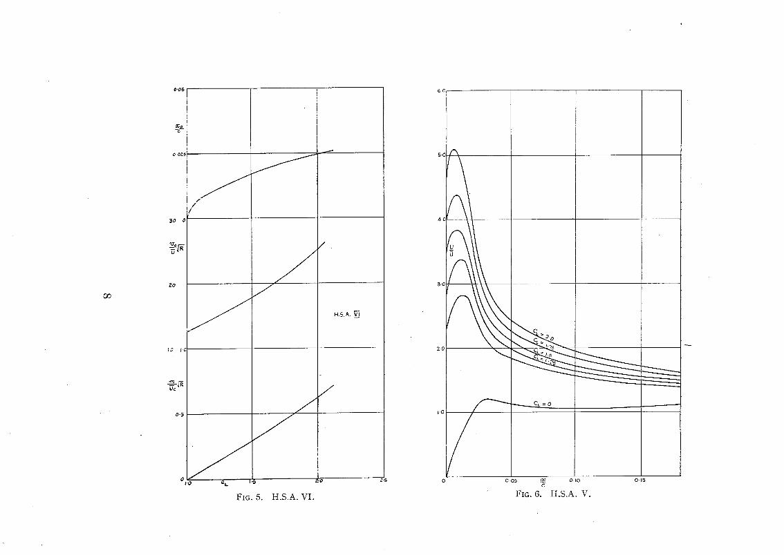
In Fig. 5, curves of (Vo/O)@R and xo/c against CL are drawn, for the par t icular aerofoil we have been considering. The total quan t i t y Q of air to be sucked per uni t t ime per uni t span is easily found as follows : - -
c U
and a curve of (Q/Oc)@R against CL can be drawn as in Fig. 5 from the two previous curves.
4. The Three Aerofoils and Remarks Thereon.--(i) H.S .A .VI . - -Th i s aerofoil was designed for a very high-speed fighter for which a high max. CL is desirable. Leading-edge porous suction is l ikely to be fit ted to an exper imenta l aircraft , and calculations were made to de termine the amoun t of air required to be sucked.
The aerofoil is 7 per cent. th ick and has a leading-edge radius curva tu re equal to 0"01c.
Figures 3, 4, 5 per ta in to this aerofoil. We assume that , wi thou t suction, a CL of 1.0 cam be a t ta ined.
4

(ii) H .S .A.V. - -Th i s aerofoil was designed as a possible high-speed aerofoil, in which the velocity distribution at CL = 0 .1 was such that the magnitude of the maximum velocity is small except for a sharp velocity peak near the nose. Figs. 8 and 6 show the shape of the aerofoil and the velocity distribution over the upper surface at CL ----- 0.1, and also for some high lift coefficients. The considerations which led to its design are that as the Mach number increases, a weak shock wave will appear first near the leading edge, but this will not unduly affect the drag. Eventually, of course, a much stronger shock wave will occur further back when the flow is super- sonic over a large part of the surface, but it is conjectured that, in this way, a high critical Mach number is achieved for the thickness of 10 per cent. The behaviour above the critical Mach number, of course, may well be more adverse than usual. However, apart from high-speed characteristics, this aerofoil has an extremely large leading-edge radius of curvature, equal to that of a normal 20 per cent. thick wing. The effect of this small curvature at the nose is strikingly shown in Fig. 6 where it is clear that the velocity gradients at large CL's are far less severe than on more ordinary aerofoils (cf. Fig. 3).
Calculations were made of the amount of suction required on this aerofoil t o produce high lift coefficients, and the results are shown in Fig. 7.
(iii) EQH 1260.--Calculations were performed on this aerofoil, since it was intended to fit a porous nose on to an aeroplane which flies with this aerofoil. Fig. 9 shows the results.
(iv) Remarks.--Comparing the graphs of (Q/Uc)vZR for each of these three aerofoils, it is clear "that the effect of a large leading-edge radius of curvature is considerable. The amount of suction required on EQH 1260 is about five times that for H.S.A. V, and this is a very strong argument for proper leading-edge design.
The advantage of porous suction over a leading-edge slot of the type considered in this report is overwhelmingly plain. For a leading-edge slot, a CL.of 1.5 required m/Oc = 0.0175 on an ordinary 10 per cent. thick aerofoil, whereas porous suction will enable this CL to be attained for a quantity given by rn/Uc = 0"0001 at a Reynolds number of 9 × 10t Porous suction therefore requires in this case, one two-hundredth of the quanti ty required for the slot.
Conclusion.--It has been demonstrated that porous suction over the leading edge of an aerofoil is a means of obtaining high lift far more economical than sucking air through a slot with the intention of altering the pressure distribution to delay the stall. Estimates have been made of the amounts of air to be porously sucked through the leading edge to obtain high lift coefficien ts on three ra~her different aerofoils : the design of the leading edge is seen to be impor tan t
N o . , A u t h o r
1 Thwaites, B . . . . .
2 Lighthill, M.J. ..
3 Goldstein, S . . . . .
4 Thwaites, B . . . . .
5 Thwaites, B . . . . .
REFERENCES
Title, etc.
On the Design of Aerofoil Sections for High-Speed Aircraft. A.R.C. 9076. October, 1945. (Unpublished.)
A Theoretical Discussion of Wings with Leading-edge Suction. R. & M. 2162. May, 1945.
A Theory of Aerofoils of Small Thickness. Part I. Velocity Distributions for Symmetrical Aerofoils. A.R.C. 5804. May, 1942. (To be published.)
On the Flow past a Flat Plate with Uniform Suction. A.R.C. 9391. February, I946. (To be published.)
Investigations into the Effect of Continuous Suction on Laminar Boundary-layer Flow under Adverse Pressure Gradients. A.R.C. 9555. April, 1946. (To be published.)
5

4-0
55
~.0
CL=I-5 \ \ ~;.oo,~,
2-0 ~ \
I-5 U ~ ,-..,....
I.O
090.8~jo
O,"7
0"6
0"3
/ 0-1
0 02
u_ Uo \
04
\ / J
/ /
f ~
0'6 0-8 I-0 ~ 'u.__.o 1.2 Uo,,
FIG. 2
J
1.4 1.6 ~8
/ /
r.6
I-4
1.2
I-O 8~o -~-~
0.8
0.4
0-2
0 2.0
o.J ~ 0.2 c
FIG. I
0.5

U u
I .
S
o o 0 5 o l o . ~,~
FIG. 3
IO
FULL LINES - AERO~'OII~S DISTRIBUTION DOTTED LINES-COMPARABLE THEORETICAL'
DISTRIBUTION
oe i
0"6 " \ y \ U \
0.4 \k TM ~ ' \ ~ cffl.o \ ~ C~., 5
\ \ ~ C L= 2"0 \
\ \ CL=I 5 c c 2 o
0",~ t t J i I J i I ]
OI 02 03 04 06 06 0"7 08 O9 IoFOR Ct~IO~SCALES/ FOR x ~ Uo~ J 02 0-4 06 OB I0 12 14 FOR CL~IS'.FOR DIFFERENTCI~s
I 02505095 ,0 '25 IS FOR CL~2() [
oL I I I I I 005 :~: 0 I0 015 C
FIG. 4
0"06
c,
o. oz
3o o
20
~ .~ | . .~
0.5
0
/ /
/
J
J
J
c t .
FIG. 5. H.S.A. VI.
r f
H.5. A.
J
z-5
~ c
5c j
4.C
3.0
~ "~-o
i.o ~ ''''-'-~CL =O
0 0.05 ~ o.to 0.15 c
FIG. 6. I t . S . A . V .

O.OS
¢
0.07.~
20 o
I0 0']
O.~e.
I-0
/ /
/ I
I
f
J z
c~. 1.5
FIG. 7.
I,I
0'9
,0"8
O."T
/
O'ZO
OC 0 e.
0'10
~.o o
dO
O 4,
Z.o
H.S.A.V.
~lJp~e E;ur.F~..~ Va.loc.jl:;~ ~ C4. = 0-!
Z'5
2. .....
jZ /
/ /
/ /
/
C~'lb;¢~l M~Lck Numbs., '=0.8 ~= ¢--~.=0.!
Y
1.0 1'.5 Z.o ,?..~,
FIG. 9
C Po,~;~m I ~ s i g n For a H|qh...~SF~.~,:I Ae,"oFo;I. e% ~hir..k-H.S.A.
t:~G. 8
9 (82240) W t . 11 9/49 H w . PR[NTED IN GREAT BRITAIN

(9809)
Publications of the o
Aeronautical Research Committee TECHNICAL ..REPORTS OF T H E AERONAUq?ICAL RESEARCH
C O M M I T T E E - -
I934-35 Vol. I. Aerodynamics. 4os. (4os. 8d.) Vol. II. Seaplanes, Structures, Engines~ Materials, etc.
4os. (4os. 8d.) ~935-36 Vol. I. Aerodynamics. 3os. (3os. 7d.)
Vol. II. Structl..res, Flutter, Engines~ Seaplanes, etc. 3os. (3os. 7d.)
I936 Vol. I. Ae~'odynamics General, Performance, Airscrews, Flutter and Spinning. 4os. (4os. 9d.)
Vol. I1. Stability and Control, Structures, Seaplanes, Engines, etc. 5os. (5os. Iod.)
1937 Vol. I. Aer,,dynamics General, Performance~ Airscrcws, Flutter and Spinning. 4os. (4os. 9 &)
Vol. I1. Stability and Control, Structures, Seaplancs, Engines, etc. 6os. (6Is.)
x938 Vol. I. Aerodynamics General, Performance, Airscrcwo, 5os, (5 is.)
Vol. II. Stabilky and Contrel, Flutter, Structures, Seaplanes, Wind Tunnels, Materials. 3os. (3es. 9d,)
ANNUAl[, REPORTS OF T H E AERONAUTICAL RESEARCH C O M M I T T E E - -
i933-34 Is. 6d. (ts. 8d.) I934-35' is. 6d. (Is. 8d.)
April I, I935 to December 3x, x936. 4.s. (4s. 4d.) x937 2s. (2s. 2d.) x938 Is. 6d. (Is. 8d.)
INDEXES TO T H E TECHNICAL REPORTS OF T H E ADVISORY C O M M I T T E E ON A E R O N A U T I C S ~
December I, ~936--June 3o, ~939. R. & M. No. I85o. ~u_y I, I939 - J u n e 3o, I945'. R. & M. No. I95o. u_y ~, T945 - J u n e 30, ~946. R. & M. No. 2o5o. £[uiy x, I 9 4 6 - December 3 I, ~946. R. & M. No. 215o. anuary i~ I947 - - June 3% I947. R. & M. No. ~25o.
Prices in brackets include postage.
Obtainable from
Majesty s Stationery London W.Co~ : York House, Kingsway
[Post OrclcIs~P.O. Box No. 569, London, S.g.I.] ~o:linburgh ~ ~' I3A Castle Street Manchester z : 39 King Street Birmingham 3 : a Edmund Stree': Cardiff: I St. Andrew's Crescent Bristol I : Tower Lane Belfast : 8o Chichester Street
or through any bookscller.
Is. 3 d. (IS. 5d.) Is. ( is. ~d,) Is. (xs. id,) xs, 3d, (is, 4d,) Is. 3d. (~s. 4d.)
ONce
S.O. Coda No. z3-224z