an evaluation of ploughing models for orthogonal machining · material around the edge of an...
TRANSCRIPT

D. J. Waldorf
R. E. DeVor
S. G. Kapoor
Mechanical and Industrial Engineering Department,
University of Illinois at Urbana-Champaign, Urbana, IL 61801
An Evaluation of Ploughing Models for Orthogonal Machining An analytical comparison is made between two basic models of the flow of workpiece material around the edge of an orthogonal cutting tool during steady-state metal removal. Each has been the basis for assumptions in previous studies which attempt to model the machining process, but no direct comparison had been made to determine which, if either, is an appropriate model. One model assumes that a separation point exists on the rounded cutting edge while the other includes a stable build-up adhered to the edge and assumes a separation point at the outer extreme of the build-up. Theories of elastic-plastic deformation are employed to develop force predictions based on each model, and experiments are performed on 6061-T6 aluminum alloy to evaluate modeling success. The experiments utilize unusually large cutting edge radii to isolate the edge component of the total cutting forces. Results suggest that a material separation point on the tool itself does not exist and that the model that includes a stable build-up works better to describe the experimental observations.
Introduction
Machining forces vary as the size and shape of the cutting edge changes. Since Merchant's shear plane model does not account for the effect of the cutting edge, accurate process models-must extend the theory to account for the forces due to ploughing by the edge. Unfortunately, little is known for certain about the interaction between the edge and the oncoming workpiece material. The small size of the edge (values of edge radii typically range between 0.1 mm and 20 /um or less) and the fact that the edge is obscured from view by the chip make direct study of the interaction very difficult. The first studies on a ploughing component of cutting forces in orthogonal machining were presented by Masuko [1] and Albrecht [2], who found ploughing forces to be considerable, though many of their methods and conclusions have been seriously questioned. Since then a number of other authors have attempted to clarify the existence and importance of ploughing forces [3-9] and to link them with the concepts of cutting process dynamics [10-14], machined surface quality [15, 16], and worn tool forces [7, 17-19]. Much disagreement and debate has ensued, leaving the issue unresolved and an accepted model of ploughing unformulated. Most researchers agree however that ploughing does contribute to the cutting forces, though they disagree on the significance of the contribution.
Modern studies of machining process models typically attempt to incorporate ploughing by assuming some simple model for the material flow around the cutting edge. Different theories have developed but little work has been done to systematically evaluate contrasting models, partially because of the difficulty in isolating the ploughing contributions to the total forces when machining with a small cutting edge radius. The focus of this paper is to concentrate on the two models of material flow most often assumed in the literature. The first is based on the assumption of a material separation point directly on the cutting edge at which oncoming workpiece material is diverted to either form the chip or rejoin the workpiece. The second model postulates the existence of a stable build-up of workpiece material which adheres to the edge, creates a larger effective clearance face for the tool, and diverts material at its outer extreme or edge. Two approaches for analyt
Contributed by the Manufacturing Engineering Division for publication in the JOURNAL OF MANUFACTURING SCIENCE AND ENGINEERING. Manuscript received Nov.
1997; revised Sept. 1998. Associate Technical Editor: D. Stephenson.
ical prediction of ploughing and shearing forces are derived to represent these models. Each approach is based on theory previously developed for the elastic-plastic indentation of solids. Ploughing and shearing components are then estimated separately from the total forces measured during orthogonal cutting tests using tools with large edge radii. The use of large edge radii ensures that considerable ploughing will occur, resulting in an easier decomposition of force components and a more robust evaluation of the ploughing models. A comparison of experimental and analytical results shows that the model with a stable build-up works better to describe the experimental observations, supporting the existence of a stable build-up for the materials and conditions used in the study. The large edge tests also reveal limitations of the force prediction strategy and the need for a more complex model valid for cutting with a small edge but based on the idea of a stable build-up adhered to the edge.
Models for Material Flow Around the Cutting Edge Nearly all process modeling studies in which ploughing is
considered assume a physical scenario of material flow based on one of the two models described here:
1 Separation Point on Edge. Several studies [5, 7, 10, 11, 14, 15, 20, 21] have proposed a physical scenario at the tool tip (Fig. 1) in which material approaches the rounded edge (a circular segment is typically assumed) of the stationary tool (shown with 0 rake angle and clearance angle yc), diverges at some separation point S, and joins the chip above (with uncut chip thickness f„ and shear angle <$>) and the workpiece below (with ploughed thickness layer S). The locating angle as for the separation point (see Fig. 1) has been estimated to be anywhere from 60 [22] to 76 [4, 23]. In some studies [2, 5, 20, 24] the material joining the workpiece is assumed to be plastically strained and does not recover above the level of the bottom of the tool (level i in Fig. 1). In another [25], plastic recovery is suggested (level ii). Others [7, 10, 11, 14, 15, 21] assume full elastic recovery in which the workpiece recovers to the height of S after it has passed the tool (level iii). Though these heights are typically difficult to measure during normal cutting, Sarwar and Thompson [9] found the latter explanation unlikely based on slow-speed tests with large edge radii simulating the sawing process.
2 Stable Build-up on Edge. By contrast, a number of researchers [3, 4, 9, 26] have proposed a situation similar to that
550 / Vol. 121, NOVEMBER 1999 Copyright © 1999 by ASME Transactions of the ASME
°
° °
-

Workpiece
Fig. 1 Cutting with material separation point on edge with 3 recovery scenarios
shown in Fig. 2 of a stable build-up adhered to the rounded edge and inclined at some angle t//. Oncoming workpiece material is thought to diverge at the tip or outer extreme of the build-up rather than on the tool itself: Several studies [24, 27] present evidence of such a stable build-up occurring in negative-rake machining as might be expected near the bottom of the edge. The presence of the build-up is important from a modeling standpoint because it represents a considerably larger area of flank or clearance face contact for ploughed material (i.e., material rejoining the workpiece) as compared to that in the absence of a build-up, especially for large values of as. Stresses act on this area separate from those that are involved with the bulk shearing of the material. Some visual evidence of the build-up has been reported [4, 9, 24] and some theoretical arguments forwarded [3], but very little experimental data has been presented in support of it—mainly due to the difficulty in measuring and separating the ploughing component of force from the total forces.
Analytical Force Prediction Both shearing and ploughing forces will be predicted based on
the different scenarios discussed above. The shearing forces are determined similarly in the two cases, based on a shear flow stress and normal pressure on the shear plane. Ploughing forces, however, are predicted using two different approaches. The first is based on elastic-plastic cylindrical indentation of a half-space and corresponds to the notion of a separation point on the surface of the rounded edge (Fig. 1). The cutting tool, with its assumed cylindrical edge radius, represents a cylindrical indenter when no build-up is present, while the workpiece represents a half-space
ration point, the material is displaced downward below the bottom of the edge and either recovers behind the edge, is compressed into the workpiece, or is pushed to the sides forming a side burr. The theory of cylinder indentation can be used to model this mechanism provided that it is modified to account for the simultaneous sliding of the indenter.
Shearing Components. The forces on the tool due to the shearing mechanism can be determined using the classical approach [28] of treating the shear zone as a thin shear plane approximated as a slip-line oriented at an angle 4> with respect to the cutting velocity direction (as shown in Fig. 1). Once the material shear flow stress k is known the shearing force parallel to the shear plane F, can be computed according to
k • tu • vv/sin (</>) (1)
where tu is the uncut chip thickness shown in Fig. 1 and w is the width of cut. It should be noted, however, that both t„ and the shear angle <f> are computed differently than in the classical treatment of orthogonal cutting—though each converges to the classical result as the edge radius decreases to zero and the amount of ploughing is negligible. The uncut chip thickness differs from the nominal feedrate/by the thickness of the layer of ploughed material S, i.e.,
t.+ 8=f. (2)
The geometry of Fig. 1 leads to a more complicated expression for the shear angle than is used in [28] because of the influence of the edge radius re and the ploughed layer 8
tan tan
IT a 4 + 2
tan 2 + «
p-re-8-S2 tc cos (a)
• tan (a) (3)
provided that the width of cut is large compared to the length of indenting contact. The second approach is also based on an elasticplastic model but assumes a blunt indentation of the flat bottom of a built-up region (Fig. 2). Though both models were originally developed for static indentation they are modified here to account for the simultaneous sliding and indenting action of a cutting edge.
1 Force Prediction based on Separation Point on Edge. The first model for material flow at the tool tip includes a round cutting edge, which can be approximated by a rigid cylinder, and a separation point directly on the edge. The oncoming workpiece material above the separation point undergoes a shearing deformation as it becomes the machined chip as described by the classical research on orthogonal machining [28]. Below the sepa
where a is the rake angle and tc is the thickness of the machined chip. The force normal to the shear plane F„ can be determined by considering the shear plane to be a slip-line rotated an angle of TT/4 4> from the maximum shear stress direction at the free surface of the unmachined workpiece. The normal force on the shear plane (due only to shearing) is then given by
F„ F x n A s
1 + 2 4> (4)
which is the equation proposed by [29] for a non-strain-hardening material. The force components due to shearing in the cutting (horizontal) and thrust (vertical) directions, F'c and F\ respectively,
Journal of Manufacturing Science and Engineering NOVEMBER 1999, Vol. 121 / 551
-
-
—
=
-

Workpiece
Stable Build-up
Fig. 2 Cutting with a stable build-up on edge
are obtained by rotating the shearing components obtained from Eqs. (1) and (4)
F ; = / V cos (</>) + F „ • sin (<£)
F', Fn cos O ) Fs • sin (4>). (5)
Ploughing Components. The ploughing force components are obtained using an elastic-plastic model for cylinder indentation built upon the well-known elastic solution. Details on the solution for the contact of a long rigid cylinder with a purely elastic half-space can be found in Johnson [30] but a summary is presented here. The interface between the cylinder and the half-space will follow the profile of the cylinder, but the area of contact will be small and can be assumed to be planar with width 2a as shown in Fig. 3. A normal pressure p(x) acts on the interface. An elliptical distribution is typically assumed, given by
p « / V - v / ( i - (6)
where P0 is the maximum pressure in the center of contact (x0) and p(x) goes to zero at the ends of contact (x ±a). P0 is related to the total load P by
IP
iral (7)
and P is related to the half-space material properties and the cylinder radius (analogous to the cutting edge radius) re by
P4(1 v2)re
l (8)
where E is the elastic modulus, v is Poisson's ratio, and / is the contact length corresponding to the width of the workpiece during orthogonal machining. For a static normal load, the maximum shear stress is equal to .3P0 and is located a distance of .78a below the center of contact. However, for a simultaneously applied tangential load as in the case of a sliding cylinder, Smith [31] has shown that the maximum shear stress is at the surface and equal to A3P0 assuming a Coulombic friction coefficient of 0.3 (approximately equal to that observed in the current tests). For such a case, the maximum half-contact length prior to yield is
2(1 v2)re •*• yield
.43£ (9)
P(x)
^ / t t h 2a
Fig. 3 Elastic contact of cylinder with half-space
552 / Vol. 121, NOVEMBER 1999
where k is the material shear yield stress. The maximum force for elastic contact can be found by inserting the value for ayieId in Eq. (9) into Eq. (8).
An elastic-plastic model of cylinder indentation based on the finite element method has been developed [32] which builds on the purely elastic model. It was found that the vertical displacement of a rigid cylinder into a half-space at the onset of plasticity is approximately
Syield = 4 . 7 5 x yield
2T(10)
Simulations of the finite element model were then performed [32] with applied loads in excess of the yielding load. The results showed that for a material exhibiting relatively little strainhardening a relationship exists between the relative load and vertical displacement of the cylinder. In a cutting situation, the displacement 8 corresponds to the thickness of the ploughed layer S in Fig. 1. A graph of the relative load-displacement relationship derived in [32] is shown in Fig. 4. Its validity was demonstrated for ratios of applied load P up to five times the load required for plastic yield PyiM. Some further experimental work has been performed to verify the relationship for higher ratios of P/PyiM. Details are given in a later section.
For the case of orthogonal machining, ploughing forces can be estimated based on these relationships. First, the normal load at the instant of plastic yield Pyicid and the corresponding depth of indentation <5yield are computed using Eqs. (8), (9), and (10). Then the relationship in Fig. 4 is used to relate these values and the thickness of the ploughed layer of material 5 to the required normal load P. The thrust direction force due to ploughing F", is equal to one half of P since only half of the tool cylinder contacted the workpiece (see level i in Fig. 1) during the sliding of the cutting edge; i.e.,
F"= 0.5 -P (11)
A tangential force component Q arises due to friction from the sliding edge. The friction contact along the interface is assumed to
10
P/Pyield
Fig. 4 Relative displacement vs load for cylinder indentation, from [32]
Transactions of the ASME
'
= -
"
-
=
= =
= -
_

a p = k ( l + 7 t )
Fig. 5 Classical slip-line field for blunt indentation [33]
be adhesive in nature with the shear stress proportional to the flow stress by a friction factor m. It is assumed that for the small values of 8 found in the experiments, the contact area is approximately parallel to the workpiece surface. The cutting direction force due to ploughing F"c is given by
F"c Q (m • k) • r„ • cos 1 (12)
The total forces are simply the sum of the shearing and ploughing components calculated from Eqs. (5), (11), and (12).
2 Force Prediction Based on Stable Build-up on Edge. The second model for material flow at the cutting edge described in the Introduction includes a stable build-up of material which adheres to the rounded edge and causes the oncoming material to diverge at its outer extreme. Material above this point is sheared into the chip much as in the classical approach. Material below this point is displaced downward below the bottom of the edge as in the previous model, but it contacts the long bottom surface of the build-up (see Fig. 2). The theory of blunt indentation can be used to model the indenting action of the relatively flat bottom surface of the build-up and predict forces during ploughing, again provided some account is taken of the sliding of the tool.
Shearing Components. The shearing forces for the second model are computed with many of the same equations used for the first. The shear plane is treated as a slip-line, and Eqs. (1) and (4) are used to determine Fs and F„. The shear plane angle $, however, can be computed with the more familiar [28] equation
4> tan
1 cos (a)
1 sin (a) tr
(13)
Equations (5) are then used to compute the cutting and thrust forces due to shearing F'c and F',.
Ploughing Components. The ploughing forces are based on an elastic-plastic model derived for blunt indentation based on a classical slip-line solution for a flat indenter. The solution for the yielding pressure on a flat, or blunt, rigid two-dimensional frictionless indenter acting on a rigid-perfectly plastic solid is described in the classical theory of plasticity [33]. It is based on a slip-line field for incipient plastic flow as shown in Fig. 5. The hydrostatic component of stress ap is equal to the material shear yield stress k at the free surface. ap then increases following the slip-line as it turns an angle of TT/2 radians according to
ap k + 2-k-fi k-(l + TT) (14)
where 0 is the angle turned by the slip-line (positive counterclockwise). Finally, the normal stress a at the indenter interface is related to crp through a Mohr's circle rotation according to
a k + ap • sin (2TJ) k • (2 + IT) 5.14 • k (15)
where TJ is the inclination of the slip-lines at the indenter (-n TT/4 for frictionless contact).
Shaw and DeSalvo [34] studied the pressure distribution on a blunt indenter causing elastic-plastic deformation in an extensive body. They found that for a flat or nearly flat indenter virtually no upward flow appears at the sides of the indenter as compared to wedge indentation, and the normal pressure under elastic-plastic conditions is given by
a=5.5-k. (16)
The total load P is related to the normal pressure through
P a-2a-l. (17)
where, again, 2a is the indenter width and / is the length of contact (width of cut). The relationship in Eq. (16) is a modification to the theory proposed in classical slip-line field studies and includes the added effects due to elastic compression of the body. The result is a predicted load approximately 7 percent larger than that predicted by the classical theory and was shown [34] to explain some discrepancies observed when the classical theory was applied to experimental results.
The blunt indenter of Shaw and DeSalvo's model corresponds to the flat bottom of the built-up region shown in Fig. 2. As in the cylinder indentation model the length / of the indenter contact is equal to the width of cut w. The length of the bottom of the stable build-up seen in Fig. 2 corresponds to the width 2a of the blunt indenter. The half-width a then varies with the measured rake angle and thickness of the ploughed layer according to
a 0.5 IT a
rr • tan | -^ + + (5)2 (18) tan (90 + a)
and is inclined to the cutting velocity direction (see Fig. 2) by
iji tan IT a 4 + 21 tan (90 + a) • tan +
(19)
Though inclined, the angle is small enough that the indenter is still considered blunt based on the definitions and results found in [34]. Equations (16), (17), and (18) are used along with a shear flow stress k to estimate an indenting force P. Although the indenter model is derived for a frictionless case, it is assumed that the normal load is unchanged by friction and that a friction force Q, which acts over the same area, is again determined by assuming adhesive contact and a friction factor m
Q 2 • (m • k) • a • w (20)
Predicted cutting and thrust components are obtained by rotating P and Q by iji according to
F"c Q-cos (i//) + />-sin(i/0
F'\= P-cos (i|/) Q-sin (tp). (21)
Journal of Manufacturing Science and Engineering NOVEMBER 1999, Vol. 121 / 553
=
= = '
=
= — =
=
'
-
= = =
=
= = =

Fig. 6 Observed rake angle ( - 2 0 deg) on 0 deg rake tool; f .197 mm, re .7938 mm
These two force models, which represent the different scenarios for ploughing, will be used to compare predicted and observed forces during cutting. Although it is admitted that many assumptions were made to formulate the models, it is anticipated that the trends observed in both the data and the theoretical predictions will be enough to show whether one model performs significantly better than another—and whether there is reason to assume the existence of a stable build-up.
Experimentation
Both static indentation tests and orthogonal machining tests were performed. The static tests were meant mainly to verify the force-displacement relationship described in the elastic-plastic model of cylinder indentation and to extend the relationship to ratios of PIPylM greater than 5 (see Fig. 4). The machining tests were conducted to estimate the material shear flow stress at the shear plane and to compare predicted and observed ploughing forces using the two models for ploughing.
Static Indentation Tests. Indenters (actually, Kennametal KC850 coated carbide inserts) with a cylindrical edge of radius .7938 mm were fed at 8 mm/min into the 2.988 mm wide edge of a stationary hollow tube of 6061-T6 aluminum mounted in a lathe chuck. Feeding of the tool continued for distances ranging from .2 to .5 mm beyond the point of first contact. Forces were simultaneously read from a Kistler 9257A 3-component dynamometer connected to a personal computer. Following each indentation the workpiece edge was traced by a profilometer to measure the indentation depth.
Orthogonal Machining Tests. Orthogonal machining tests were carried out by turning the edge of a hollow tube using cutting inserts of both small and large edge radii. All tests were carried out on 6061-T6 aluminum workpieces of 6 in. diameter with varying wall thicknesses of approximately 3 mm. The hollow cylindrical workpieces were fit with a solid circular base plate to increase stiffness and reduce static deflection of the tube. Kennametal KC850 coated carbide inserts with standard nose radii of .7938 mm and .3969 mm were used. The small edge tests were run with a rake angle of 0 and a clearance angle of 11°. For cutting with large edge radii, the insert was clamped in a tool holder and the holder rotated 90 so that the tool nose was used as the cutting edge during cutting. In these tests, the triangular shape of the inserts gave a clearance angle of 30 with a rake angle of 0°, though observations of the insert after the cut indicated that the workpiece material never touched the actual clearance face of the tool (see level i in Fig. 1). In all tests the cutting speed V was kept at a constant 300 m/min, well above the speed range typically associated with unstable built-up edges. The feedrate/varied from 0.00615 mmpr to 0.8 mmpr. A fresh insert edge was used for each cut, and approximately 1 mm of the workpiece was removed with a nominally sharp insert before each cut to remove any burr or
hardened layer that may have remained from a previous cut with a large edge radius.
Cutting forces, using the dynamometer described above, and several other quantities were carefully measured for each test, including the dimensional change of the workpiece, the mass and dimensions of the machined chip, and the dimensions of the side burr of material left on the workpiece due to ploughing. When the uncut chip thickness was less than approximately one half the edge radius, the exiting chip material left the tool at an angle different from the tool rake angle. In those cases, a video camera with zoom focus and close-up lenses was used to observe an average rake angle (see Fig. 6). This observed angle is used in Eqs. (3), (13), (18), and (19) for calculation of forces rather than the nominal rake angle (held constant at 0°). The average thickness of the machined chip tc is computed from the chip mass, length, and average width. Since steady-state forces were reached during the tests, it can be reasoned that the thickness of material displaced per pass was equal to the set feedrate. However, a significant amount of side burr formed due to the heavy ploughing resulting from the large edges. The total thickness of the displaced material is therefore equal to the sum of the ploughed thickness 8 and the uncut chip thickness f„ as suggested by Eq. (2). f„ is computed from the total volume of the removed chip, the average chip width, and the number of revolutions observed in the force signals (corresponding to a distance or length cut). S is estimated as the difference between the set feedrate and tu. Independent measurements of the volume of material in the side burrs confirmed the approximate accuracy of the estimate of S. The measurements also confirmed that in all tests the volume of the side burr formed by the ploughing action plus the volume of the machined chip approximately summed to the volume of material displaced as measured by the dimensional change of the workpiece. In other words, material volume was approximately conserved during the cut and the ploughed material was essentially pushed to the side rather than pushed into the workpiece.
Results and Discussion
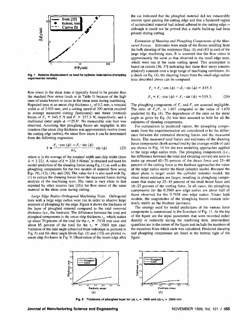
Static Indentation Tests. Based on the measured forces and the surface profile traces performed on the indented workpiece, several points are added to the relative force-displacement plot of Fig. 4. Values for Syield and Pyil,u are obtained using Eqs. (8), (9), and (10), the aluminum material properties listed in Table 1, and / 2.988 mm. The denominator in Eq. (9) is replaced with 0.3£ because no tangential load was applied (see [31]). Utilizing the measured normal force P and displacement 8, the results are plotted with the original curve in Fig. 7 and show a consistent trend as the applied load increases. A curve was fit to the data, as shown in Fig. 7, resulting in the expression
s / p y-5
> — 0.35 + 0 . 6 5 . (22) "yie ld \ ' y i e l d /
Though this equation only represents the static relationship between indenting load and displacement, a similar relationship is assumed to hold for the normal load of a cylinder that is both indenting and sliding.
Small Edge Radius Orthogonal Machining Tests. Cutting tests with a nominally sharp insert edge (radius less than .02 mm) are used to estimate the material flow stress of the aluminum in the shear zone at approximately the conditions used for the large edge radius tests. Though partially offset by higher temperatures, the
Table 1 Standard material properties for 6061-T6 aluminum
Elasticity Modulus, E 69,000 N/mm2
Poisson's Ratio, V 0.3
Shear Yield Stress, k 159 N/mm2
554 / Vol. 121, NOVEMBER 1999 Transactions of the ASME
~ = =
=
= - = —
°
°
°
1(C
1 from [32] Indent, test! Curve fit 1/
10 P/Pyield
too
Fig. 7 Relative displacement vs load for cylinder indentation (including experimental results)
the cut indicated that the ploughed material did not measurably recover upon passing the cutting edge and that a hardened region of accumulated material had indeed adhered to the cutting edgealthough it could not be proved that a stable build-up had been present during cutting.
Estimation of Shearing and Ploughing Components of the Measured Forces. Estimates were made of the forces resulting from the bulk shearing of the workpiece [Eqs. (1) and (4)] in each of the large edge machining tests. It is assumed that the flow stress is approximately the same as that observed in the small edge tests, which were run at the same cutting speed. This assumption is based on results [36, 37] indicating that shear flow stress remains relatively constant over a large range of machining conditions. As a check on Eq. (4), the shearing forces from the small edge radius tests described above can be computed
flow stress in the shear zone is typically found to be greater than the standard flow stress (such as in Table 1) because of the high rates of strain known to occur in the shear zone during machining. Repeated tests at an uncut chip thickness t„ of 0.2 mm, a nominal width w of 3.023 mm, and a cutting speed of 300 m/min resulted in average measured cutting (horizontal) and thrust (vertical) forces of Fc 545.5 N and F, 357.5 N, respectively, and a traditional shear angle 4> 25.8°. No measurable side burr was observed. Assuming that ploughing forces are negligible in this situation (the uncut chip thickness was approximately twelve times the cutting edge radius), the shear flow stress k can be determined from the following expression
kFc• cos (</>) F,• sin (<£)
wtu
sin (<j>) (23)
where w is the average of the nominal width and chip width (here vv 3.22). A value of k 226.5 N/mm2 is obtained and used for model prediction of the shearing forces using Eq. (1) as well as the ploughing components for the two models of material flow using Eqs. (9), (12), (16), and (20). The value for k is also used with Eq. (1) to extract the shearing forces from the measured forces during analysis of the machining tests. The value is very close to that reported by other sources (see [35]) for flow stress of the same material in the shear zone during cutting.
Large Edge Radius Orthogonal Machining Tests. Orthogonal tests with a large edge radius were run in order to observe large amounts of ploughing by the edge. Figure 8 shows the thickness of the layer of ploughed material compared to the total removed thickness (i.e., the feedrate). The difference between the total and ploughed components is the uncut chip thickness /„, which makes up about 70 percent of the total for the re .7938 mm case and about 85 percent of the total for the re .3969 mm case. Variation of the rake angle (observed from videotape as pictured in Fig. 6) and the shear angle [from Eqs. (3) and (13)] are plotted vs. uncut chip thickness in Fig. 9. Observation of the insert edge after
Fs Fc • cos (4>) F,• sin (c/>) 335.5
Fn F, • cos (4>) + Fc • sin (<£) 559.3. (24)
The ploughing components of Fc and F, are assumed negligible. The ratio of FJFS is 1.667 compared to the value of 1.670 predicted by Eq. (4). The dependence of the ratio on the shear angle as given by Eq. (4) was thus assumed to hold for all the estimates of shearing components.
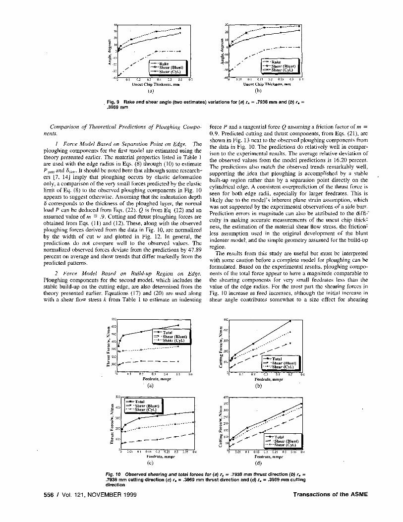
For comparison to predicted values, the ploughing components from the experimentation are considered to be the difference between the estimated shearing forces and the measured forces. The measured total forces and estimates of the shearing force components (both normalized by the average width of cut) are shown in Fig. 10 for the two modeling approaches applied to the large edge radius tests. The ploughing components (i.e., the difference between the total and shearing curves) are seen to make up around 60-70 percent of the thrust force and 25-40 percent of the cutting force as the feedrate approaches the value of the edge radius under the blunt indenter model. Because the shear plane is larger under the cylinder indenter model, the shear stress estimates are larger, resulting in ploughing components that make up 25-45 percent of the total thrust force and 10-25 percent of the cutting force. In all cases, the ploughing components for the 0.3969 mm edge radius are about half of those observed for the 0.7938 mm edge radius. Under both models, the magnitudes of the ploughing forces remain relatively stable as the feedrate increases.
The strategy used for model predictions of the various force components is summarized in the flowchart of Fig. 11. At the top of the figure are the input parameters that were recorded either directly or indirectly during the machining tests. Intermediate quantities are in the center of the figure and include the numbers of the equations from which each was calculated. Predicted shearing and ploughing components are listed at the bottom right of the figure.
0.2 0.3 0.4
Feedrate, mmpr
(a) Feedrate, mmpr
(b)
Fig. 8 Thickness of ploughed layer for (a) r, .7938 and (b) re .3969 mm
Journal of Manufacturing Science and Engineering NOVEMBER 1999, Vol. 121 / 555
—
= — =
= =
= = =
— =
= =
= =
= =
- R a k e ' "Shear (Blunt) - S h e a r (Cyl.)
0 0 1 0.2 0 3 0.4 0.5 0.6
Uncut Chip Thickness, mm
(a)
20
$ 10
$ o •D jf-10 "5D a
-(-20
-30 ,
__-« *• * M — • *
**
—•--Rake 1 - • - S h e a r (Blunt) 1
Shear (Cyl.) |
0.05 0.1 0.15 0.2 0.25 0.3
Uncut Chip Thickness, mm
(b)
Fig. 9 Rake and shear angle (two estimates) variations for (a) r, •• .3969 mm
.7938 mm and (b) re ••
Comparison of Theoretical Predictions of Ploughing Components.
1 Force Model Based on Separation Point on Edge, The ploughing components for the first model are estimated using the theory presented earlier. The material properties listed in Table 1 are used with the edge radius in Eqs. (8) through (10) to estimate Pyield and 8yieM. It should be noted here that although some researchers [7, 14] imply that ploughing occurs by elastic deformation only, a comparison of the very small forces predicted by the elastic limit of Eq. (8) to the observed ploughing components in Fig. 10 appears to suggest otherwise. Assuming that the indentation depth 8 corresponds to the thickness of the ploughed layer, the normal load P can be deduced from Eqs. (22). Q is from Eq. (12) and an assumed value of m .9. Cutting and thrust ploughing forces are obtained from Eqs. (11) and (12). These, along with the observed ploughing forces derived from the data in Fig. 10, are normalized by the width of cut w and plotted in Fig. 12. In general, the predictions do not compare well to the observed values. The normalized observed forces deviate from the predictions by 47.89 percent on average and show trends that differ markedly from the predicted patterns.
2 Force Model Based on Build-up Region on Edge. Ploughing components for the second model, which includes the stable build-up on the cutting edge, are also determined from the theory presented earlier. Equations (17) and (20) are used along with a shear flow stress k from Table 1 to estimate an indenting
force P and a tangential force Q assuming a friction factor of m0.9. Predicted cutting and thrust components, from Eqs. (21), are shown in Fig. 13 next to the observed ploughing components from the data in Fig. 10. The predictions do relatively well in comparison to the experimental results. The average relative deviation of the observed values from the model predictions is 16.20 percent. The predictions also match the observed trends remarkably well, supporting the idea that ploughing is accomplished by a stable built-up region rather than by a separation point directly on the cylindrical edge. A consistent overprediction of the thrust force is seen for both edge radii, especially for larger feedrates. This is likely due to the model's inherent plane strain assumption, which was not supported by the experimental observations of a side burr. Prediction errors in magnitude can also be attributed to the difficulty in making accurate measurements of the uncut chip thickness, the estimation of the material shear flow stress, the frictionless assumption used in the original development of the blunt indenter model, and the simple geometry assumed for the build-up region.
The results from this study are useful but must be interpreted with some caution before a complete model for ploughing can be formulated. Based on the experimental results, ploughing components of the total force appear to have a magnitude comparable to the shearing components for very small feedrates less than the value of the edge radius. For the most part the shearing forces in Fig. 10 increase as feed increases, although the initial increase in shear angle contributes somewhat to a size effect for shearing
700
g 600
g 500
V 400 a*
£ 300 tb tS 200 3 L
£.100
o,
_ _ _ - .
r^~~~ —•-Total * "Shear (Blunt)
--•--Shear (Cyl.)
0.3
Feed rate, mmpr
(a)
b z
jS^ . * •
•'"' * *
— • Total 1 » "Shear (Blunt) 1
--»- Shear (Cyl.) |
0.2 0,3
Feedrate, mmpr
(b)
500
E £
Z f 300
Total 1 * "Shear (Blunt) 1
"-•--Shear (Cyl.) 1
350 E g 300
r
Cut
ting
For
ce/w
, IN
0 0.05 0,1 0.15 0.2 0.25 0.3 0.35 0
Feedrate, mmpr
(c)
4 u0
//-*'— • Total 1
• -Shear (Blunt) 1 --'--Shear (Cyl.) |
0.05 0.1 0.15 0.2 0.25 0.3 0.35 0.4
Feedrate, mmpr
(d)
Fig. 10 Observed shearing and total forces for (a) r„ .7938 mm thrust direction (b) re
.7938 mm cutting direction (c) r, .3969 mm thrust direction and (d) r8 .3969 mm cutting direction
556 / Vol. 121, NOVEMBER 1999 Transactions of the ASME
' ~~~ —
_ — •
—
=
=
-
—
"
-—
-
.
—— —
--
—-
= = = =

Small Edge Tests Large Edge Tests
tc, t„, a , w ,F c , F,
1 (13)
H | 1 (23)
tC! tu, rc, a , w, f
Test Results
Assumed m
Q, F„ Fn
(1)(4)(8)(12) (17)(20X22)
F'C) F'„ F"c, F",
Fig. 11 Flowchart and equations for force component prediction
forces. The ploughing forces, on the other hand, begin to level off as the feed grows and might be expected to remain constant for feeds much larger than re. It is possible that the ploughing forces could continue to increase, owing perhaps to a rising S as total forces increase. However, some experimentation with small edge tools (which indicated that the ploughing/side burr increased as the rake angle became more negative, not as the feed increased) and the reasonable flow stress obtained from Eq. (23) have led the authors to believe that S and the ploughing forces do not continue to increase with feedrate—thereby justifying the neglection of ploughing in the computation of k. In either case, an iterative procedure may be appropriate in which one first obtains the flow stress neglecting ploughing, then computes the ploughing forces, and then re-computes the flow stress using only shearing forces. The procedure would result in a lower calculated flow stress (approximately 10% here) and, if used on the current data, lower shearing forces—thus giving a better match in the thrust direction of the predicted and experimental ploughing forces in Fig. 13.
The results for cutting with a large edge may also be applicable to the more typical case of a very small cutting edge radius, though that extension should be made with caution. The width of cut-toedge radius ratio (about 4:1 and 8:1 in the current study) which resulted in the observed side burr may be considerably larger in normal cutting and correspond to a different approximation of plane strain. Nevertheless, it is anticipated that the modeling
success of the big edge tests will be useful in predicting build-up geometry and ploughing forces under normal cutting conditions.
Summary and Conclusions
The results of this study provide considerable insight into modeling the additional forces required to plough material when cutting with a rounded cutting edge of large radius. Two different approaches were taken in attempts to model the ploughing process and predict the resulting forces. One of the models assumed cylindrical indentation with a material separation point directly on the edge, while the other considered the blunt indentation of a stable build-up region adhered to the edge. Cutting tests with large edge radii were run and the ploughing and shearing components of force estimated for each. Upon comparing the forces with the model predictions, the model which accounts for a stable build-up was more successful in matching the trends and magnitudes of the experimental results. The results contribute to a greater understanding of the geometric model for the cutting edge and should expedite development of a more complete model of orthogonal cutting.
The results demonstrate that for cutting with a large edge radius on 6061-T6 aluminum:
a significant side burr will be formed to the side of the workpiece without joining the chip
large ploughing forces compared to shearing forces are expected when the feedrate is at or below the value of the edge radius
a stable build-up adheres to the cutting edge and influences the cutting forces considerably
theoretical models can be formulated to account for ploughing.
Further work should attempt to formulate a more sophisticated model for ploughing based on the idea of a stable build-up adhered to the edge. Classical plasticity methods, as have been applied to machining problems in the past, or modern finite element methods, which can accommodate sophisticated material models (such as a flow stress which varies with temperature, strain, and strain rate) and a more accurate three-dimensional representation, are needed to verify a model for ploughing in normal machining. Because of
Observed Predicted (Cyl.)
Nominal Feedrate, mmpr
(a)
"Observed -Predicted (Cyl.)
Nominal Feedrate, mmpr
(b)
540 y^—^ 120 / 100
80
60 J S J S —• Observed 1
20 — » Predicted (Cyl.) |
0.05 0.1 0.15 0.2 0.25 0.3 0.35
Nominal Feedrate, mmpr
(c) (d)
0 0.05 0.1 0.15 0.2 0.25 0 3 0.35 0 4
Nominal Feedrate, mmpr
Fig. 12 Observed and predicted ploughing forces using cylinder indenter model for (a) r, .7938 mm thrust direction (b) re .7938 mm cutting direction (c) re .3969 mm thrust
direction and (d) re .3969 mm cutting direction
Journal of Manufacturing Science and Engineering NOVEMBER 1999, Vol. 121 / 557
—
—
—
—
-
-
-
" -
= = = =

600
£ 500
E
g 400
i£ 300 fc~200 f*
^
• Observed 1 —»-Predicted (Indent) |
0.2 0.3 0.4 0.5 Nominal Feedrate, mmpr
(a)
0.1 0.2 0.3 0.4 0.5
Nominal Feedrate, mmpr
(b)
350
300
E 250 E
Z 2 0 0
•? 150
•"• Observed 1 --•—Predicted (Indent) |
0.05 0.1 0.15 0.2 0.25 0,3 0,35 0.4
Nominal Feedrate, mmpr
(c)
v0 0.05 0.1 0.15 0.2 0.25 0,3 0.35 Nominal Feedrate, mmpr
(d)
Fig. 13 Observed and predicted ploughing forces using blunt indenter model for (a) re
.7938 mm thrust direction (b) r, .7938 mm cutting direction (c) r. .3969 mm thrust direction and (d) r. .3969 mm cutting direction
the repeated observations of a side burr due to ploughing, it is also hoped that the model can add to an understanding of the phenomenon of side burr and perhaps form a basis for a model of side burr formation.
References 1 Masuko, M., "Fundamental Research on Metal Cutting (1st Report), A New
Analysis of Cutting Forces, Trans. JSME, v. 19, 1953, pp. 32-39. 2 Albrecht, P., "New Developments in the Theory of the Metal-Cutting
Process, Part 1. The Ploughing Process in Metal Cutting, ASME JOURNAL OF ENGINEERING FOR INDUSTRY, November, 1960, pp. 348-357.
3 Palmer, W. B., and Yeo, R. C. K., "Metal Flow Near the Tool Point during Orthogonal Cutting with a Blunt Tool, Proc. 4th Int. MTDR Conf., 1963, pp. 61-71.
4 Moneim, Abdel, M. Es., "Tool Edge Roundness in Finish Machining at High Cutting Speeds, Wear, Vol. 58, 1980, pp. 173-192.
5 Iwata, K., Osakada, K., and Terasaka, Y., "Process Modeling of Orthogonal Cutting by the Rigid-Plastic Finite Element Method, ASME Journal of Engineering Materials and Technology, Vol. 106, April, 1984, pp. 132-138.
6 Parthimos, Dimitris, and Ehmann, Komel F., A Model for the Stress Field Around the Shear Zone, Trans, of NAMRI/SME, Vol. 21, 1993, pp. 197-204.
7 Elanayar, V. T„ Sunil and Yung C, Shin, "Modeling of Tool Forces for Worn Tools: Flank Wear Effects, Materials Issues in Maching-II and The Physics of Machining Processes-II, Proceedings of the Winter Annual Meeting of ASME and the Fall Meeting of the Minerals, Metals, and Materials Society, 1994, pp. 341-361.
8 Rubenstein, C , "The Edge Force Components in Oblique Cutting, Int. J. Mack Tools Manufact., Vol. 30, No. 1, 1990, pp. 141-149.
9 Sarwar, M., and Thompson, P. J., "Cutting Action of Blunt Tools, Proc. 22nd Int. MTDR Conf, 1981, pp. 295-304.
10 Wu, D. William, A New Approach of Formulating the Transfer Function for Dynamic Cutting Processes, ASME JOURNAL OF ENGINEERING FOR INDUSTRY, Vol. I l l , February 1989, pp. 37-47.
11 Endres, W. J„ DeVor, R. E„ and Kapoor, S. G., A Dual-Mechanism Approach to the Prediction of Machining Forces, Parts 1 and 2, ASME JOURNAL OF ENGINEERING FOR INDUSTRY, Vol. 117, November 1995, pp. 526-541.
12 Elbestawi, M. A., Ismail, F., Du, R„ and Ullagaddi, B. C , "Modelling Machining Dynamics Including Damping in the Tool-Workpiece Interface, Tribo-logical Aspects in Manufacturing, ASME WAM, PED-Vol. 54/Trib-Vol. 2, 1991, pp. 253-264.
13 Montgomery, D., and Altintas, Y., "Mechanism of Cutting Force and Surface Generation in Dynamic Milling, ASME WAM, PED-Vol. 40, 1989, pp. 65-74.
14 Sisson, T. R., and Kegg, R. L., "An Explanation of Low-Speed Chatter Effects, ASME JOURNAL OF ENGINEERING FOR INDUSTRY, November, 1969, pp. 951958.
15 Haslam, D„ and Rubenstein, C , "Surface and Sub-surface Work-hardening Produced by the Planing Operation, Annals of the CIRP, Vol. 18,1970, pp. 369-381.
16 Thomsen, E. G., Lapsley, J. T., Jr., and Grassi, R. C , "Deformation Work Absorbed by the Workpiece During Metal Cutting, Trans. ASME, May 1953, pp. 591-598.
17 Usui, E., Shirakashi, T., and Kitagawa, T., "Analytical Prediction of Cutting Tool Wear, Wear, Vol. 100, 1984, pp. 129-151.
18 Danai, K., Nair, R., and Malkin, S., "An Improved Model for Force Transients in Turning, ASME JOURNAL OF ENGINEERING FOR INDUSTRY, Vol. 114, Nov., 1992, pp. 400-403.
19 Moneim, Abdel, M. Es. and Scrutton, R. F., "The Tribology of Cutting Tools during Finish Machining. I and II, Wear, Vol. 25, 1973, pp. 45-63.
20 Roth, R. N., and Oxley, P. L. B„ "Slip-line Field Analysis for Orthogonal Machining Based Upon Experimental Flow Fields, J. Mechanical Engr. Science, Vol. 14, No. 2, 1972, pp. 85-97.
21 Rubenstein, C , Lau, W. S., and Venuvinod, P. K., "Flow of Workpiece Material in the Vicinity of the Cutting Edge, Int. J. MTDR, Vol. 25, No. 1, 1985, pp. 91-97.
22 Rubenstein, C , Groszman, F. K., and Koenigsberger, F., "Force Measurements during Cutting Tests with Single Point Tools Simulating the Action of a Single Abrasive Grit, Proc. Int. Industrial Diamond Conf, Vol. 1, 1966, p. 161.
23 Komanduri, R., "Some Aspects of Machining with Negative Rake Tools Simulating Grinding, Int. J. MTDR, Vol. 11, 1971, pp. 223-233.
24 Heginbotham, W. B., and Gogia, S. L., "Metal Cutting and the Built-up Nose, Proc. Inst. Mech. Engrs., Vol. 175, No. 18, 1961, pp. 892-905.
25 Moneim, Abdel, M. Es. and Scrutton, R. F., "Post-Machining Plastic Recovery and the Law of Abrasive Wear, Wear, Vol. 24, 1973, pp. 1-13.
26 Abebe, Minasse, and Appl, F. C , A Slip-line Solution for Twodimensional Steady State Machining with a Stagnant Region at the Tip of the Tool,Proc. 11th NAMRC, 1983, pp. 291-298.
27 Kita, Y., Ido, M., and Kawasaki, N„ A Study of Metal Flow Ahead of Tool Face with Large Negative Rake Angle, ASME JOURNAL OF ENGINEERING FOR INDUSTRY, Vol. 104, August, 1982, pp. 319-325.
28 Merchant, M. E., "Basic Mechanics of the Metal-Cutting Process, ASME Journal of Applied Mechanics, Vol. 66, 1944, pp. A168-A175.
29 Oxley, P. L. B., Mechanics of Machining: An Analytical Approach to Assessing Machinability, Ellis Horwood, Chichester, 1989.
30 Johnson, K. L„ Contact Mechanics, Cambridge University Press, New York, 1985.
31 Smith, J. O., "Stresses Due to Tangential and Normal Loads on an Elastic Solid with Application to Some Contact Stress Problems, ASME Journal of Applied Mechanics, June, 1953, pp. 157-166.
32 Dumas, G., and Baronet, C. N., "Elastoplastic Indentation of a Half-space by an Infinitely Long Rigid Cylinder, Int. J. Mech. Sci., Vol. 13, 1971, pp. 519-530.
33 Hill, R., The Mathematical Theory of Plasticity, Clarendon Press, Oxford, 1950.
34 Shaw, M. C , and DeSalvo, G. J., A New Approach to Plasticity and Its Application to Blunt Two Dimensional Indenters, ASME JOURNAL OF ENGINEERING FOR INDUSTRY, May, 1970, pp. 469-479.
35 Black, J. T., "Flow Stress Model in Metal Cutting, ASME JOURNAL OF ENGINEERING FOR INDUSTRY, Vol. 101, November, 1979, pp. 403-415.
36 Shaw, M. C , and Finnie, Iain, "The Shear Stress in Metal Cutting,Transactions of the ASME Vol. 77, 1955, p. 115.
37 Bayoumi, Abdel E., Xie, Qufei, and Hamdan, M. Nader, "Effect of Cutting Conditions on Dynamic Properties and Surface Integrity of Work Material, Wear, Vol. 146, 1991, pp. 310-312.
558 / Vol. 121, NOVEMBER 1999 Transactions of the ASME
'
-
= =
=
"
"
"
" "
" "
"
" "
" "
" "
" " " -
" "
" " "
" "
" "
" "
"
" "
" " "
" - "
" "
" "