an engineer’s guide to fcc pre-scans€¦ · an engineer’s guide to fcc pre-scans ... this...
TRANSCRIPT

An Engineer’s Guide to FCC Pre-ScansHow To Reduce Risk and Speed Time to Market
by Carl Turner, Senior RF Engineer
1 www.lairdtech.comLaird
INTRODUCTION
FCC certification is a critical step in every product launch, but achieving it isn’t always straightforward. Successfully navigating the landscape of FCC certification for RF products is critical to getting to market quickly and FCC pre-scans are a great way to reduce the risk of failing. Planning for wireless compliance must be there from the very start of the design, and pre-scans are an important element to factor into your design process if you want to get to market on time.
As a manufacturer of a variety of RF products, Laird engineers have been through the FCC certification process many times. In fact, we even have our own FCC certification facility in Wisconsin, USA that can test and certify any product to FCC and world-wide compliance standards. With the number of products that we design and certify, we understand the risks and nuances of FCC testing and would like to share some of our experience and best practices with you to help you avoid potential FCC failures.
This white paper provides practical information to use in current and future RF product designs that will help you simplify the FCC testing process and pass on the first attempt.
PRE-SCAN STRATEGY: WHAT SHOULD BE TESTED IN A FCC PRE-SCAN?
Inexpensive but risky FCC strategyThere are many ways to go about designing RF products to achieve FCC approval - some riskier than others.
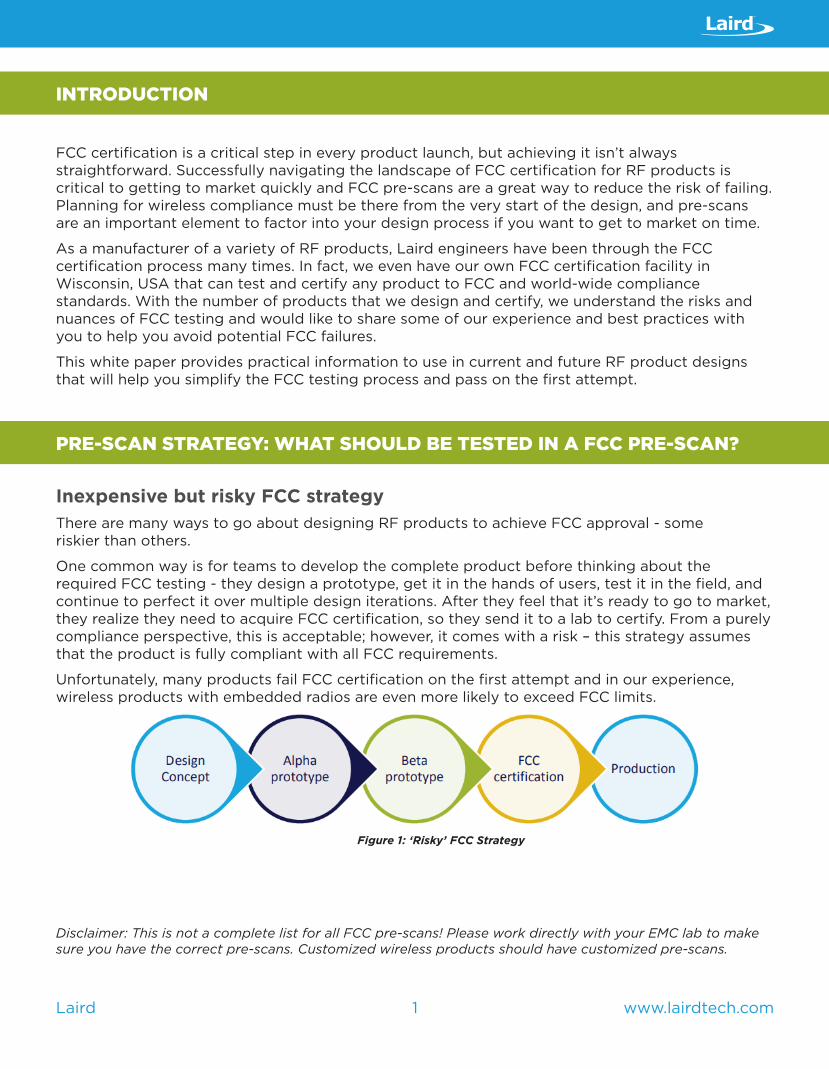
One common way is for teams to develop the complete product before thinking about the required FCC testing - they design a prototype, get it in the hands of users, test it in the field, and continue to perfect it over multiple design iterations. After they feel that it’s ready to go to market, they realize they need to acquire FCC certification, so they send it to a lab to certify. From a purely compliance perspective, this is acceptable; however, it comes with a risk – this strategy assumes that the product is fully compliant with all FCC requirements.
Unfortunately, many products fail FCC certification on the first attempt and in our experience, wireless products with embedded radios are even more likely to exceed FCC limits.
Figure 1: ‘Risky’ FCC Strategy
Disclaimer: This is not a complete list for all FCC pre-scans! Please work directly with your EMC lab to make sure you have the correct pre-scans. Customized wireless products should have customized pre-scans.
2 www.lairdtech.comLaird
Discovering these issues late in the design process can be a huge problem because resolving FCC failures typically requires hardware changes. Making hardware changes late in the game can derail a product release schedule, create manufacturing headaches, and/or significantly increase the design budget!
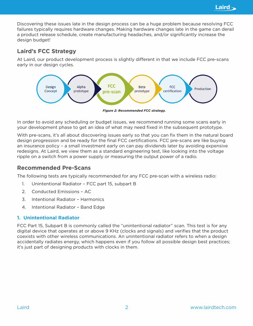
Laird’s FCC StrategyAt Laird, our product development process is slightly different in that we include FCC pre-scans early in our design cycles.
Figure 2: Recommended FCC strategy.
In order to avoid any scheduling or budget issues, we recommend running some scans early in your development phase to get an idea of what may need fixed in the subsequent prototype.
With pre-scans, it’s all about discovering issues early so that you can fix them in the natural board design progression and be ready for the final FCC certifications. FCC pre-scans are like buying an insurance policy – a small investment early on can pay dividends later by avoiding expensive redesigns. At Laird, we view them as a standard engineering test, like looking into the voltage ripple on a switch from a power supply or measuring the output power of a radio.
Recommended Pre-ScansThe following tests are typically recommended for any FCC pre-scan with a wireless radio:
1. Unintentional Radiator – FCC part 15, subpart B
2. Conducted Emissions – AC
3. Intentional Radiator – Harmonics
4. Intentional Radiator – Band Edge
1. Unintentional RadiatorFCC Part 15, Subpart B is commonly called the “unintentional radiator” scan. This test is for any digital device that operates at or above 9 KHz (clocks and signals) and verifies that the product coexists with other wireless communications. An unintentional radiator refers to when a design accidentally radiates energy, which happens even if you follow all possible design best practices; it’s just part of designing products with clocks in them.

3 www.lairdtech.comLaird
As far as the FCC is concerned, the test is about making sure a product doesn’t accidentally radiate too much and jam important communications such as emergency radios, police communications, GPS, etc. In Figure 3, we can see an example of how testing is conducted in the lab.
Figure 3: Example of testing layout.
For this test, the FCC sets the maximum allowable field-strength limits in ‘microvolts-per-meter’ (µV/m). This isn’t typically a measurement that engineers use on the bench, so it can be a confusing unit of measurement.
Below is a table that converts the FCC limits in µV/m into an equivalent measure of power – in watts. It’s clear from the table that it only takes a few nanowatts (right column), depending on the frequency, to cause a failure for this test. Just a few errant nanowatts of radiated energy can cause the product to be above the FCC’s general emissions limit and fail!
Frequency (MHz) uV/m EIRP (dBm) nW30-88 100 -55.23 2.9988-216 150 -51.73 6.71
216-960 200 -49.23 11.93960-40,000 500 -41.23 75.33
Figure 4: FCC general emissions limit - three meters
Below is a list of common and uncommon hardware examples that are high risk for radiation above the FCC general emission limits.
Common Offenders:
• LCDs – Many LCDs transmit high speed data on unshielded flexible cables between the LCD and PCB. These cables are notorious for radiating unwanted emissions.
• High Speed Digital (DDR Memory) – Designs that include high-speed digital circuitry - such as DDR memory or a high-speed end processor - are at risk of failing FCC unintentional radiator.
• Switch Mode Power Supplies – Typically found in products that have high efficiency, high switching frequency, DC to DC converters, etc.
4 www.lairdtech.comLaird
Less Obvious Offenders:
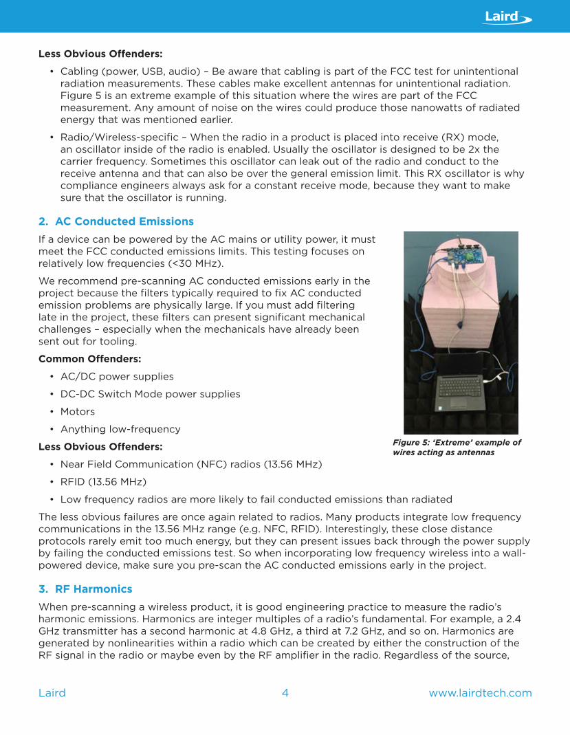
• Cabling (power, USB, audio) – Be aware that cabling is part of the FCC test for unintentional radiation measurements. These cables make excellent antennas for unintentional radiation. Figure 5 is an extreme example of this situation where the wires are part of the FCC measurement. Any amount of noise on the wires could produce those nanowatts of radiated energy that was mentioned earlier.
• Radio/Wireless-specific – When the radio in a product is placed into receive (RX) mode, an oscillator inside of the radio is enabled. Usually the oscillator is designed to be 2x the carrier frequency. Sometimes this oscillator can leak out of the radio and conduct to the receive antenna and that can also be over the general emission limit. This RX oscillator is why compliance engineers always ask for a constant receive mode, because they want to make sure that the oscillator is running.
2. AC Conducted EmissionsIf a device can be powered by the AC mains or utility power, it must meet the FCC conducted emissions limits. This testing focuses on relatively low frequencies (<30 MHz).
We recommend pre-scanning AC conducted emissions early in the project because the filters typically required to fix AC conducted emission problems are physically large. If you must add filtering late in the project, these filters can present significant mechanical challenges – especially when the mechanicals have already been sent out for tooling.
Common Offenders:
• AC/DC power supplies
• DC-DC Switch Mode power supplies
• Motors
• Anything low-frequency
Less Obvious Offenders:
• Near Field Communication (NFC) radios (13.56 MHz)
• RFID (13.56 MHz)
• Low frequency radios are more likely to fail conducted emissions than radiated
The less obvious failures are once again related to radios. Many products integrate low frequency communications in the 13.56 MHz range (e.g. NFC, RFID). Interestingly, these close distance protocols rarely emit too much energy, but they can present issues back through the power supply by failing the conducted emissions test. So when incorporating low frequency wireless into a wall-powered device, make sure you pre-scan the AC conducted emissions early in the project.
3. RF HarmonicsWhen pre-scanning a wireless product, it is good engineering practice to measure the radio’s harmonic emissions. Harmonics are integer multiples of a radio’s fundamental. For example, a 2.4 GHz transmitter has a second harmonic at 4.8 GHz, a third at 7.2 GHz, and so on. Harmonics are generated by nonlinearities within a radio which can be created by either the construction of the RF signal in the radio or maybe even by the RF amplifier in the radio. Regardless of the source,
Figure 5: ‘Extreme’ example of wires acting as antennas

5 www.lairdtech.comLaird
harmonics must be below a certain limit to pass FCC testing.
At the end of the day, if you have a radio in your product, you should consider pre-scanning it for harmonic emissions.
Figure 6: Example of a Radiated Harmonic scan
What’s often overlooked with harmonics is that many fall within one of the FCC’s restricted bands of operation. Restricted bands are dedicated to protecting sensitive wireless communications, so the FCC limits the amount of energy in those specific bands. The limits in the restricted bands are the same general emissions limits covered in the ‘unintentional radiator’ section. As before, with the general emission limits, it only takes tens of nano-watts to produce a product failure.
In figure 7 below, numbers in RED indicates that the harmonic falls within a FCC-restricted band. As you can see, the majority of 900 MHz and 2400 MHz ISM radio’s harmonics fall within the restricted bands. This is often overlooked and is sometimes over the general emissions limit.
900 MHz ISM BAND 2nd 3rd 4th 5th 6th 7th 8th 9th 10th
2.4 GHz ISM BAND 2nd 3rd 4th 5th 6th 7th 8th 9th 10th
Figure 7: FCC restricted bands
4. Band Edge The band edge measurements verify that the radio only transmits within its intended frequency band and does not interfere with the band right next to it. To do this, compliance engineers measure how much energy is right at that band.
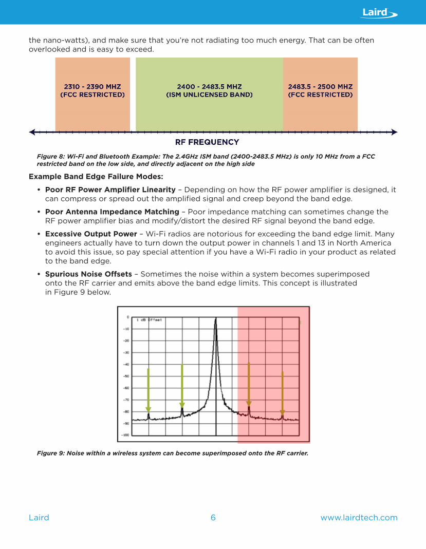
What’s often overlooked, as with harmonic emissions, is that restricted bands are often close or adjacent to the band that wireless products use. For example, devices operating in commonly used ISM bands (such as Wi-Fi or Bluetooth in the 2.4 GHz ISM Band) are only 10 MHz away from a restricted band on the low side and directly adjacent to one on the high side. Recall that a restricted band means that the product is tested against the general emissions limit (again to
6 www.lairdtech.comLaird
the nano-watts), and make sure that you’re not radiating too much energy. That can be often overlooked and is easy to exceed.
Figure 8: Wi-Fi and Bluetooth Example: The 2.4GHz ISM band (2400-2483.5 MHz) is only 10 MHz from a FCC restricted band on the low side, and directly adjacent on the high side
Example Band Edge Failure Modes:
• Poor RF Power Amplifier Linearity – Depending on how the RF power amplifier is designed, it can compress or spread out the amplified signal and creep beyond the band edge.
• Poor Antenna Impedance Matching – Poor impedance matching can sometimes change the RF power amplifier bias and modify/distort the desired RF signal beyond the band edge.
• Excessive Output Power – Wi-Fi radios are notorious for exceeding the band edge limit. Many engineers actually have to turn down the output power in channels 1 and 13 in North America to avoid this issue, so pay special attention if you have a Wi-Fi radio in your product as related to the band edge.
• Spurious Noise Offsets – Sometimes the noise within a system becomes superimposed onto the RF carrier and emits above the band edge limits. This concept is illustrated in Figure 9 below.
Figure 9: Noise within a wireless system can become superimposed onto the RF carrier.
7 www.lairdtech.comLaird
Pre-Scan Strategy SummaryTo recap, we’ve introduced four common tests that you should consider as candidate tests for a FCC pre-scan, as well as a few common failure modes to be aware of. Partnering with an EMC lab, like Laird, helpsv ensure that you have the right/best pre-scans selected for your products. Customized products require customized pre-scans.
PRE-SCAN EXECUTION: PRACTICAL ADVICE TO MAXIMIZE PRE-SCAN RESULTS
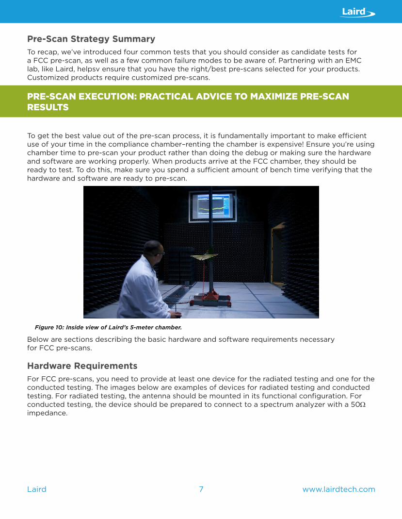
To get the best value out of the pre-scan process, it is fundamentally important to make efficient use of your time in the compliance chamber–renting the chamber is expensive! Ensure you’re using chamber time to pre-scan your product rather than doing the debug or making sure the hardware and software are working properly. When products arrive at the FCC chamber, they should be ready to test. To do this, make sure you spend a sufficient amount of bench time verifying that the hardware and software are ready to pre-scan.
Figure 10: Inside view of Laird’s 5-meter chamber.
Below are sections describing the basic hardware and software requirements necessary for FCC pre-scans.
Hardware RequirementsFor FCC pre-scans, you need to provide at least one device for the radiated testing and one for the conducted testing. The images below are examples of devices for radiated testing and conducted testing. For radiated testing, the antenna should be mounted in its functional configuration. For conducted testing, the device should be prepared to connect to a spectrum analyzer with a 50Ω impedance.

8 www.lairdtech.comLaird
Figure 11: Device for radiated testing. Figure 12: Device for conducted testing.
Software RequirementsThe FCC compliance lab also needs software to place the product and the radio into various test modes. The software must configure the product in all of the normal operational modes. If it can do something in the field, it should be tested in the lab to make sure it’s not radiating.
For wireless products, the test lab needs physical layer control of the radio – in addition to all of the normal functionality of the product. The device should be put in constant transmit mode or constant receive mode, with the engineer able to change the selected channels, power settings, data rates, etc. These software requirements are detailed in Figure 13.
Note: As previously mentioned, the constant receive mode enables an internal oscillator in the radio, so test engineers can check it against general emissions limits.
Testing InterfaceIn addition to the right hardware and software, the FCC compliance lab needs a test interface to control the product. There are many ways to create this test interface. At the end of the day, it must be intuitive so the EMC engineer can work efficiently in the chamber.
Whatever interface you decide to use, avoid having any dangling wires from the test unit – they can accidentally act as an antenna and antennas can then radiate energy.
Below are a few examples of test interfaces:

9 www.lairdtech.comLaird
Figure 13: Some test modes are needed for all products and others are more radio-specific
ALL PRODUCTS RADIO-SPECIFIC TEST MODES
– Configure the product for normal operation
– Give test engineers the ability to use all normal product features
– Constant Transmit Modes – Modulated (>98%
duty cycle)
– Un-modulated
– Constant Receive Mode*
– EMC engineers also need control of: – RF channel
selection (for both transmit and receive)
– Power settings (if adjustable)
– Data rates (if adjustable)
1. Manufacturer-provided Test Interface
Occasionally, the radio chip manufacturer providev a complete test software suite to download and use for FCC testing. This software is something you can leverage for compliance testing and is great to use for the following reasons:
– The software is already created – no additional development schedule required
– The software is tested and proven – works right out of the box
– Typically well-supported and intuitive for EMC test engineers
Figure 14: Example of manufacturer provided test software
10 www.lairdtech.comLaird
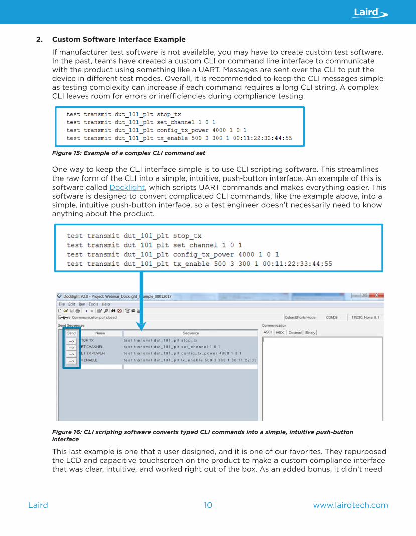
2. Custom Software Interface Example
If manufacturer test software is not available, you may have to create custom test software. In the past, teams have created a custom CLI or command line interface to communicate with the product using something like a UART. Messages are sent over the CLI to put the device in different test modes. Overall, it is recommended to keep the CLI messages simple as testing complexity can increase if each command requires a long CLI string. A complex CLI leaves room for errors or inefficiencies during compliance testing.
Figure 15: Example of a complex CLI command set
One way to keep the CLI interface simple is to use CLI scripting software. This streamlines the raw form of the CLI into a simple, intuitive, push-button interface. An example of this is software called Docklight, which scripts UART commands and makes everything easier. This software is designed to convert complicated CLI commands, like the example above, into a simple, intuitive push-button interface, so a test engineer doesn’t necessarily need to know anything about the product.
Figure 16: CLI scripting software converts typed CLI commands into a simple, intuitive push-button interface
This last example is one that a user designed, and it is one of our favorites. They repurposed the LCD and capacitive touchscreen on the product to make a custom compliance interface that was clear, intuitive, and worked right out of the box. As an added bonus, it didn’t need

11 www.lairdtech.comLaird
a test computer. This could be an example for you to model if you have a large panel display on your product to make the test interface much easier.
Figure 17: Example of a custom touch screen test interface
HOW TO EVALUATE AND INTERPRET THE PRE-SCAN RESULTS
What should you expect to receive as a deliverable from a FCC pre-scan and how do you evaluate the results?
Data Packet The data packet is the pre-scan deliverable which is typically a PDF with all of the test results. The test results are usually a series of screen captures as shown in Figure 18.
Figure 18: Example of an unintentional radiated emission scan
12 www.lairdtech.comLaird
From Figure 18, it’s immediately clear which frequencies (if any) are failing as they are highlighted and bolded in red in the test packet. Any frequencies above the limit should be investigated to determine the root cause of the emission and resolved on the next board design. It is good engineering practice to also investigate any emissions close to the FCC limits.
Don’t Overlook Measurement UncertaintyThere are a lot of moving parts when it comes to measuring radiated signals for FCC testing. Even with top-of-the-line equipment and extensive calibration procedures, radiated measurements include significant measurement uncertainty.
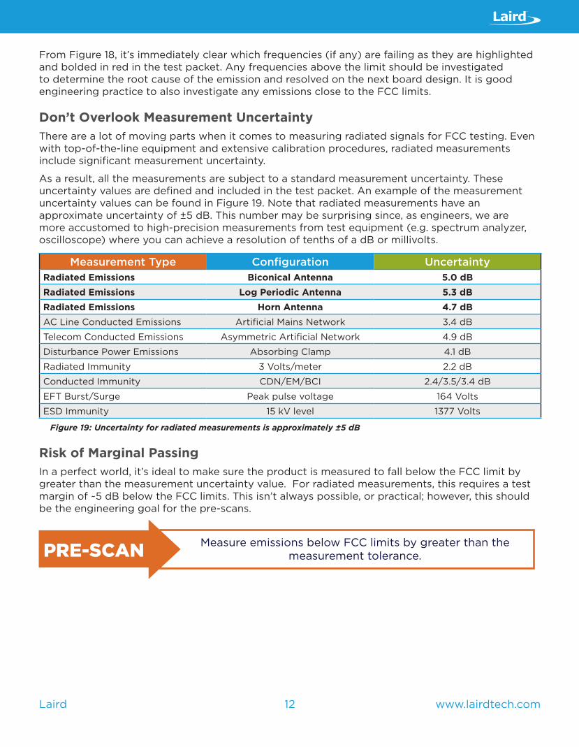
As a result, all the measurements are subject to a standard measurement uncertainty. These uncertainty values are defined and included in the test packet. An example of the measurement uncertainty values can be found in Figure 19. Note that radiated measurements have an approximate uncertainty of ±5 dB. This number may be surprising since, as engineers, we are more accustomed to high-precision measurements from test equipment (e.g. spectrum analyzer, oscilloscope) where you can achieve a resolution of tenths of a dB or millivolts.
Measurement Type Configuration UncertaintyRadiated Emissions Biconical Antenna 5.0 dBRadiated Emissions Log Periodic Antenna 5.3 dBRadiated Emissions Horn Antenna 4.7 dBAC Line Conducted Emissions Artificial Mains Network 3.4 dB
Telecom Conducted Emissions Asymmetric Artificial Network 4.9 dB
Disturbance Power Emissions Absorbing Clamp 4.1 dB
Radiated Immunity 3 Volts/meter 2.2 dB
Conducted Immunity CDN/EM/BCI 2.4/3.5/3.4 dB
EFT Burst/Surge Peak pulse voltage 164 Volts
ESD Immunity 15 kV level 1377 Volts
Figure 19: Uncertainty for radiated measurements is approximately ±5 dB
Risk of Marginal PassingIn a perfect world, it’s ideal to make sure the product is measured to fall below the FCC limit by greater than the measurement uncertainty value. For radiated measurements, this requires a test margin of ~5 dB below the FCC limits. This isn’t always possible, or practical; however, this should be the engineering goal for the pre-scans.
PRE-SCAN Measure emissions below FCC limits by greater than the measurement tolerance.

13 www.lairdtech.comLaird
CONCLUSION – BRINGING IT ALL TOGETHER
In conclusion, here are four key points to remember about FCC pre-scans:
1. Avoid an unexpected FCC failure by pre-scanning the product early in the design cycle. Investing in pre-scans will reduce the risk of significant time-to-market delays.
2. Partner with Laird compliance to select and optimize your pre-scans! We work directly with you to select your optimal pre-scans. Remember, custom products require customized pre-scans.
3. Observe the FCC’s restricted bands of operation for products with radios. These are often overlooked and only allow a small amount of radiated energy.
4. Resolve any failures on subsequent board designs and strive to pass with margin. When evaluating the pre-scan results, account for measurement of tolerances.
FOR MORE INFORMATION ON LAIRD’S EMC AND WIRELESS TESTING BY LSR, VISIT US ON THE WEB AT:
WWW.LSR.COM/TESTING

ABOUT LAIRD
WE MAKE TECHNOLOGY WORK
Laird is a global leader in solving your electromagnetic interference challenges and providing state-of-the-art wireless communication and smart system solutions. Our products are engineered with unparalleled innovation and precision and are supplied to major companies across the world, equipping them with the technology needed to improve their business and contribute to the progress of the modern world. We meet the needs of a variety of industries and applications, delivering transformational solutions for a constantly changing digital society.
• CONNECT - Stay wired at all times with our highly reliable power products and industrial communications systems.
• PROTECT - Keep heat and electromagnetic interference at bay with high quality performance materials.
• DESIGN - Design custom parts and solutions or build your entire concept from prototype to production.
LEARN MORE AT WWW.LAIRDTECH.COM