an autonomous wireless body area network implementation ... · and gsr for other human body vital...
TRANSCRIPT

SPECIAL SECTION ON BODY AREA NETWORKS
Received May 29, 2017, accepted June 6, 2017, date of publication June 16, 2017, date of current version July 7, 2017.
Digital Object Identifier 10.1109/ACCESS.2017.2716344
An Autonomous Wireless Body Area NetworkImplementation Towards IoT ConnectedHealthcare ApplicationsTAIYANG WU, (Student Member, IEEE), FAN WU, (Student Member, IEEE),JEAN-MICHEL REDOUTÉ, (Senior Member, IEEE), ANDMEHMET RASIT YUCE, (Senior Member, IEEE)Department of Electrical and Computer Systems Engineering, Monash University, Melbourne, VIC 3800, Australia
Corresponding author: Taiyang Wu ([email protected])
The work of M. R. Yuce was supported by Australian Research Council Future Fellowships under Grant FT130100430.
ABSTRACT Internet of Things (IoT) is a new technological paradigm that can connect things fromvarious fields through the Internet. For the IoT connected healthcare applications, the wireless body areanetwork (WBAN) is gaining popularity as wearable devices spring into the market. This paper proposes awearable sensor node with solar energy harvesting and Bluetooth low energy transmission that enables theimplementation of an autonomous WBAN. Multiple sensor nodes can be deployed on different positions ofthe body to measure the subject’s body temperature distribution, heartbeat, and detect falls. A web-basedsmartphone application is also developed for displaying the sensor data and fall notification. To extend thelifetime of the wearable sensor node, a flexible solar energy harvester with an output-based maximum powerpoint tracking technique is used to power the sensor node. Experimental results show that the wearable sensornode works well when powered by the solar energy harvester. The autonomous 24 h operation is achievedwith the experimental results. The proposed system with solar energy harvesting demonstrates that long-term continuous medical monitoring based on WBAN is possible provided that the subject stays outside fora short period of time in a day.
INDEX TERMS Internet of Things, wireless body area network, energy harvesting, maximum power pointtracking, Bluetooth.
I. INTRODUCTIONInternet of Things (IoT) is a new technological paradigm thatgains attention from vast research fields in the past few years[1], [2]. In the future healthcare circumstance, the IoT willconnect the subjects and the healthcare professionals seam-lessly [3], [4]. With the advancement of wearable sensors,low-power integrated circuit (IC) and wireless communica-tion technologies, the wireless body area network (WBAN) isbecoming an emerging research field worldwide [5]. WBAN,also known as body sensor network (BSN), is a wirelessnetwork to enable the health monitoring anywhere anytimearound the human body [6], [7]. This can be used for thee-health applications, such as the computer-assisted reha-bilitation, early detection of medical issues and emergencynotification [8]. In recent years, the portable devices, espe-cially smartphones, have almost been an indispensable partof people’s daily life. Therefore, they can be employed asthe gateway between the WBAN and the IoT cloud [9]–[11],as shown in Fig. 1.
Wearable sensors are the key components in the WBAN asthey collect the vital data of the human body for further usage.Researchers from multiple disciplines have presented dif-ferent wearable sensor systems for the WBAN applications.In [12], the authors present a wearable photoplethysmogra-phy (PPG) sensor for the heartbeat measurement at the ear-lobe. Another heartbeat sensor is presented in [13], which isdesignedwith the polymer-based flexible strain-gauge sensor.A wearable sensor prototype capable of measuring heart rate,blood oxygen saturation, temperature and humidity during amagnetic resonance imaging (MRI) experiment is presentedin [14]. Seeger et al. propose a middleware solution for thewearable sensor system of WBAN, which is based on thesmartphone applications [15].
Another critical issue in the development of WBAN isthe power consumption in the long-term use of wearabledevices. Energy harvesting, especially wearable energy har-vesting technology, is a promising solution to enable the long-term operation of WBAN [16]. In [17], the authors present
VOLUME 5, 20172169-3536 2017 IEEE. Translations and content mining are permitted for academic research only.
Personal use is also permitted, but republication/redistribution requires IEEE permission.See http://www.ieee.org/publications_standards/publications/rights/index.html for more information.
11413

T. Wu et al.: Autonomous WBAN Implementation Toward IoT Connected Healthcare Applications
FIGURE 1. Wireless body area network with IoT connected healthcareplatform.
a flexible energy harvesting mechanism for ultra-low powerwearable devices. It also studies the performance of a flexiblesolar panel under different irradiance levels. Hamid and Yucepresent a novel wearable energy harvester that combinespiezoelectric and electromagnetic energy sources from lowfrequency vibrations like human motion [18]. In [19], a wear-able bracelet with ultra-low power camera and microphoneis presented. It is powered by hybrid solar cells and ther-moelectric generators (TEGs), and its self-sustainability isconfirmed by simulations based on experimental measure-ments. In [20], an autonomous wearable system with energyharvesting module is designed, manufactured and tested forvital signs measurement. The wearable system powered bya flexible solar panel can be attached to a T-shirt. Anotheroptimal energy harvester using a flexible photovoltaicmoduleand a maximum power point tracking (MPPT) techniquebased on fuzzy logic is proposed in [21]. It is used to power asensor node with bluetooth low energy (BLE) module, whichcan measure heartbeat and blood pressure of the subject andsend them to a smartphone.
This paper proposes a wearable sensor node with solarenergy harvesting and BLE transmission to implement anautonomous WBAN. The solar energy harvester is controlledby an output based MPPT technique to extract the maximumpower from a flexible solar panel [22]. The sensor node isintegrated with an onboard accelerometer, temperature sensorand a plug-in PPG sensor on a flexible solar panel. Multiplenodes can be deployed on different positions of the body tomeasure the temperature distribution of the body. The nodecan also measure the heartbeat and detect the fall of the sub-ject. All the data from the sensor nodes and fall notificationwill be transmitted to a web-based smartphone applicationthrough a commercial BLE module. When the sensor node isset to an appropriate wake-sleepmode, the 24 hours operationof the sensor node powered by the solar energy harvester isachieved and verified by experiments.
The remainder of the paper is organized as follows:Section II describes the system architecture. The solar energyharvester with the output based MPPT technique is presentedin Section III. Section IV shows the experimental resultsof the solar energy harvester and the wearable sensor node.Lastly, the paper is concluded with a discussion of futureimprovement in Section V.
II. SYSTEM ARCHITECTUREThis paper presents the implementation of an autonomousWBAN towards the IoT connected healthcare applications.It consists of 3 major parts: 1) a flexible solar energy har-vester with MPPT; 2) a wearable sensor node with BLEtransmission; and 3) a smart phone application acting as theIoT gateway for sensor data visualization and emergencynotification. Fig. 2 shows the overview of the wearable sensornode with solar energy harvesting.
FIGURE 2. Flexible wearable sensor node with energy harvesting.
A. FLEXIBLE SOLAR ENERGY HARVESTERAflexible solar panel, theMPT3.6-75 from Sundance Solarr
(7.2*6.0 cm2), is chosen as the power source for the energyharvester. Due to its flexibility, it can be easily attached to thehuman body for wearable applications. To extract the max-imum power from the flexible solar panel, an output basedanalog MPPT circuit is proposed, which will be explained indetail in Section III. The harvested energy from the flexiblesolar panel is stored in a supercapacitor. Here a supercapac-itor is chosen instead of a rechargeable battery. Because asupercapacitor has almost unlimited charging cycles, and itsefficiency of charging and discharging is higher than that ofa battery [23]. An efficient buck-boost voltage regulator, theLTC3130-1 from Linear Technologyr, is adopted to connectthe supercapacitor with the wearable sensor node. The inputrange of the voltage regulator is from 2.4 V to 25 V, and itsoutput voltage is configured at 3.3 V to power the wearablesensor node.
B. WEARABLE SENSOR NODEThe main components of the wearable sensor node includea microcontroller unit (MCU) and 3 sensors for subject data
11414 VOLUME 5, 2017

T. Wu et al.: Autonomous WBAN Implementation Toward IoT Connected Healthcare Applications
measurement and processing. The software diagram of thewearable sensor node is illustrated in Fig. 3.
FIGURE 3. Software diagram of the wearable sensor node.
1) MCUThe core of the wearable sensor node is the MCU, which isused to collect and process the sensor data, as well as performpower management to reduce the overall power consumption.The MCU used in the sensor node is the ATmega328P fromAtmelr due to its low power, low cost and high performance.The CPU speed of the MCU is configured to 8 MHz at3.3 V, and it can be throttled down to 1 MHz at 1.8 V forextremely low power applications. TheMCU has 32 KB flashmemory with 2 KB SRAM, 6 analog input pins and 14 digitalI/O pins. Therefore, the proposed wearable sensor node canbe connected with other plug-in sensors such as ECG, EEGand GSR for other human body vital signals measurement inthe future designs.
2) ACCELEROMETERThe ADXL362 from Analog Devicesr is selected and sol-dered on the flexible PCB in the wearable sensor node. It is a3-axis MEMS accelerometer with ultralow power consump-tion, which consumes less than 2 µA when the output datarate is 100 Hz and only 270 nA when it is in the motiontriggered wake-up mode. The motion triggered wake-upmode is one of the most notable features of the accelerometer,and it has adjustable threshold of the sleep/wake motion acti-vation. In the proposed wearable sensor node, the ADXL362accelerometer is used for ‘‘fall detection’’ in the WBANapplications. Whenever a fall is detected, the ADXL362
wakes the MCU up and an emergency notification will besent to the smartphone of the medical assistant through theBLE module.
3) TEMPERATURE SENSORThe second onboard sensor is a temperature sensor, theMAX30205 from Maximr. It is chosen due to its highaccuracy (0.1◦C from 37◦C to 39◦C), high resolution (16-bit)and low power consumption (600 µA at 2.7 V to 3.3 V). TheMAX30205 temperature sensor can also provide an overtem-perature alarm and communicate with the MCU throughan I2C-compatible 2-wire serial interface. The temperaturesensor measures the body temperature distribution when thewearable sensor node is placed at different positions of thebody.
4) PULSE SENSORA commercial pulse sensor is adopted in the wearable sensornode for subject heartbeat monitoring. The pulse sensor isa plug-in PPG sensor, which is only connected to the sen-sor node deployed at the subject’s wrist. The pulse sensorconsists of the low power light photo sensor (APDS-9008)and amplifier (MCP6001) with the typical supply current of42 µA and 100 µA, respectively. By appropriate configura-tion, the pulse sensor can measure the heartbeat of the radialartery at the wrist instead of the fingertip, thus it will notinterfere with the subject’s daily life.
C. BLE TRANSMISSION AND SMARTPHONEAPPLICATIONTo help the medical assistant in analysing the data fromthe wearable sensor node, a BLE module (HM-10) is usedto transmit the sensor data of the subject to a smartphone.The BLE module incorporates CC2541 chip from TexasInstrumentr, which is a bluetooth low energy compliantand proprietary RF system-on-chip. The CC2541 is highlysuited for low power consumptions as its RX and TX currentsare 17.96 mA and 18.2 mA respectively. The BLE modulecan communicate with most of the iOS and Android smart-phones with Bluetooth 4.0 on the market. For the sensordata visualization, a web-based smartphone application usingthe Evothingsr platform is developed. The Evothings is aplatform that enables wrapping up the CSS, HTML5 andJavascript code depending upon the device platform, insteadof relying on the platform-specific APIs in the Android oriOS systems. Every smartphone with the Evothings Viewerapplication installed can access the sensor data through thedesigned application. This will help the medical assistantor family member monitor the subject’s health conditionscontinuously.
Fig. 4 shows the PCB design for the wearable sensornode with the energy harvesting and the MPPT circuit(5.0*4.8 cm2). The sensor circuit is fabricated with a flexi-ble PCB, together with the flexible solar panel, the node iswearable and can be attached to the subject easily.
VOLUME 5, 2017 11415

T. Wu et al.: Autonomous WBAN Implementation Toward IoT Connected Healthcare Applications
FIGURE 4. Flexible PCB design for the wearable sensor node circuit withMPPT (5.0*4.8 cm2).
FIGURE 5. The electrical equivalent circuit of a solar panel.
III. SOLAR ENERGY HARVESTER WITH MPPTA. SOLAR PANEL AND MPPTA solar panel, also known as a photovoltaic (PV) module, isa nonlinear semiconductor device that absorbs the energy ofthe light and converts it into electricity. The electrical energygenerated by the solar panel varies with the environmentalconditions. An electrical equivalent circuit model of the solarpanel is proposed in [24], as shown in Fig. 5. The current-voltage (I-V) characteristic of the solar panel can be givenby:
IPV = IPH − I0(eq(VPV+IPV RS )
ηkT − 1)−VPV + IPVRS
RSH(1)
where IPH is the photo current, I0 is the dark saturation currentof the diode, q is the electronic charge, η is the ideality factorof the diode, k is the Boltzmann’s constant and T is thetemperature in Kelvin.
According to (1), the IPV and VPV , as well as the corre-sponding power (PPV ) of the solar panel , depend on the lightirradiance level (IPH ) and temperature (T ). Fig. 6 shows theI-V and P-V characteristics of a solar panel under differentirradiance levels. It can be seen that the solar panel canoutput the maximum power at a certain point, which iscalled the maximum power point (MPP). However, the MPPmoves due to the variation of the irradiance level and other
FIGURE 6. I-V and P-V characteristics of a solar panel under differentirradiance levels.
environmental conditions. Therefore, to harvest the maxi-mum power from a solar panel, the MPPT circuit is usuallyadopted within the power management unit in a solar energyharvesting system.
So far, there have been a lot of studies on the maxi-mum power point tracking techniques for the application ofsolar energy harvesting [25], [26]. One of the most com-monly used MPPT techniques is the perturbation and obser-vation (P&O) [27], which is an iterative method to reachthe MPP of a solar panel. It measures both the voltage andcurrent to calculate the power of the solar panel and per-turbs the operating point by changing the duty cycle of theDC-DC converter used in the solar energy harvester peri-odically. If the power from the solar panel increases, theP&O will keep the change of the duty cycle in the samedirection; otherwise, it will change the duty cycle in theopposite direction. Eventually the duty cycle will oscillatearound a value corresponding to the MPP, where the solarpanel can output the maximum power. The implementation ofthe P&O technique is complex as it needs both the voltage andcurrent to calculate the power [28]. Another common MPPTtechnique is the fractional open circuit voltage (FOCV) tech-nique [29], which assumes the voltage at the MPP is pro-portional to the open circuit voltage of the solar panel. Itsimplifies the implementation of the MPPT circuit as onlythe voltage is required for the measurement. The limitationof FOCV is that the proportion of the voltage at the MPP tothe open circuit voltage is based on the experimental obser-vation. The proportion varies with the irradiance level andtemperature, which means the tracking of MPP is not alwaysprecise. There are also other MPPT techniques, like the incre-mental conductance (IC), short circuit current (SCC) andtemperature based MPPT technique [25]. With the improve-ment of microcontroller processing power, researchershave proposed more intelligent MPPT techniques, likethe fuzzy logic control (FLC) and the neural networktechnique [26].
11416 VOLUME 5, 2017

T. Wu et al.: Autonomous WBAN Implementation Toward IoT Connected Healthcare Applications
FIGURE 7. Block diagram of the flexible solar energy harvester.
B. PROPOSED OUTPUT BASED MPPT TECHNIQUEIn this work, the wearable sensor node is powered by aflexible solar energy harvester, whose block diagram is shownin Fig. 7. The flexible solar panel and the load is connectedby a buck-boost converter, consisting of L1,L2,C1 and M1.To harvest the maximum power from the solar panel, anoutput based MPPT technique is proposed to control theduty cycle (D) of the buck-boost converter for impedancematching [30].
For the buck-boost converter, the relationship of the input(VPV & IPV ) and output (VOUT & IOUT ) can be expressed as:
VPV =1− DD
VOUT (2)
and
IPV =D
1− DIOUT (3)
Thus the equivalent resistance of the output load seen fromthe input side of the buck-boost converter is:
Req =(1− D)2
D2 Rload (4)
From the I-V characteristic of the solar panel in Fig. 6, thereexists a resistance (RMPP = VMPP/IMPP) corresponding totheMPP. This means the solar panel can output the maximumpower when the load resistance equalsRMPP. By changing theD in (4), the equivalent resistance Req can be matched to theRMPP, therefore the MPP of the solar panel is reached.To measure the power of the solar panel, conventional
MPPT techniques (like P&O) multiply the VPV and IPV atthe input side of the DC-DC converter. The proposed MPPTtechnique focuses on the output side and only needs oneparameter. For a constant resistive load (Rload ) at the outputside, the output power is:
POUT = I2OUTRload (5)
Considering the efficiency η of the buck-boost converter, theinput power from the solar panel is:
PPV =I2OUTRload
η(6)
According to (6), the power of the solar panel has the samechanging trend of the output current IOUT . The proposedMPPT measures the IOUT , and then changes the (D) of the
buck-boost converter (increase). If the measured IOUT alsoincreases, the MPPT circuit will keep changingD in the samedirection (increase); otherwise the MPPT circuit will changeD in the opposite direction (decrease). Through this method,the D will be fixed around a certain value while the IOUT ismaximum, which means the power of the solar panel is alsomaximum. For a variable load or supercapacitor, the aboveanalysis can still be applicable. As in a short period time, thevariable load or the supercapacitor can be treated like a fixedload. As long as the variation of the load or supercapacitor iswithin the tracking time of the MPPT circuit, the solar panelwill operate around its MPP and output the maximum power.
FIGURE 8. Circuit design of the output based MPPT technique.
The implementation of the proposed MPPT circuit isshown in Fig. 8. The IOUT is sensed by a small resis-tor Rsense (in Fig. 7), thus IOUT can be represented byVsense, which is amplified to V
′
sense for accurate process-ing. V
′
sense is the input of the first differentiator, whichconsists of Opamp1,R1,R2,C1 & C2. The output of thedifferentiator indicates the changing trend of V
′
sense: theCTsense is low when V
′
sense increases and CTsense is highwhen V
′
sense decreases. The second differentiator consistingof Opamp2,R5,R6,C3 & C4 has the similar configurationand is used to detect the changing trend of VD (CTD). VD isthe voltage of C6, and it is compared with a triangle wavegenerated by a 100 KHz clock, R7 & C5. The comparisonresult is the final output of theMPPT circuit, which is a PWMsignal used to drive the buck-boost converter. Because VD isproportional to the duty cycle value of the PWM signal, itschanging trend CTD represents the changing trend of the dutycycle.
The changing trend of the IOUT and D, which are denotedbyCTsense andCTD respectively, are used to track theMPP ofthe solar panel. The simulation result of the tracking processby LTspicer is illustrated in Fig. 9. The CTsense is the controlsignal input of the multiplexer and the rising edge D flip-flop. The CTD and its inverted value are the inputs of the
VOLUME 5, 2017 11417

T. Wu et al.: Autonomous WBAN Implementation Toward IoT Connected Healthcare Applications
FIGURE 9. Tracking process of the output based MPPT technique.
multiplexer. The output of the multiplexer is the input of theD flip-flop. The output of the D flip-flop, Next D, is usedto charge or discharge C6, which changes the duty cycleof the PWM signal. When the IOUT increases, the CTsenseis low thus the output of the D flip-flop (Next D) will notchange. The change of the duty cycle will be kept in the samedirection (increase/decrease). When the IOUT decreases, theCTsense is changed to high. The multiplexer will output theinverted value of the changing trend of the duty cycle to theD flip-flop, thus the D flip-flop changes its output Next D.Then the duty cycle will be changed in the opposite direction(decrease/increase) to track the MPP of the solar panel. Thistracking process will continue to control the solar panel tooperate around its MPP. Note there are delays in the detectionof the IOUT and VD, therefore the D flip-flop with rising edgeis used in the tracking process.
IV. EXPERIMENTAL RESULTSA. FLEXIBLE SOLAR ENERGY HARVESTERThe solar energy harvester with the output based MPPT isfabricated and tested with a flexible solar panel. To val-idate the performance of the proposed MPPT circuit, thecharacteristics of the flexible solar panel under differentweather conditions are measured and shown in Fig. 10. The‘‘direct sunlight’’ indicates that the solar panel is exposedto sunlight directly, while ‘‘artificial shadow’’ means usinga paper board to block the direct sunlight to simulate thecloudy weather. The MPP of the flexible solar panel occursaround 3 V and 2.5 V under the direct sunlight and artificialshadow, respectively. Fig. 11 shows the experimental resultof charging a 12.5 F supercapacitor with rate voltage of 5.4 V(two 25 F supercapacitor with rate voltage of 2.7 V in series)using the solar energy harvester with the MPPT circuit. Thesupercapacitor can be charged while the solar panel operatesaround 3 V under direct sunlight and changes to around 2.5 Vwhen artificial shadow occurs. This verifies that the proposedMPPT circuit can control the solar panel to operate around itsMPP under different environmental conditions.
FIGURE 10. I-V (a) and P-V (b) characteristics of the flexible solar panelunder the experimental condition.
FIGURE 11. Performance of the solar energy harvester with MPPT circuit.
TABLE 1. Time of charging a 12.5 F supercapacitor from 2.4 V to 5.4 V.
The solar energy harvester consists of a flexible solarpanel, a buck-boost converter, the MPPT circuit and a super-capacitor for energy storage. Table 1 shows the chargingperformance of the solar energy harvester under different con-ditions. As the supercapacitors in series have a rate voltage of5.4 V and the lowest input of the voltage regulator is 2.4 V,
11418 VOLUME 5, 2017

T. Wu et al.: Autonomous WBAN Implementation Toward IoT Connected Healthcare Applications
the charging time in Table 1 refers to the time of charging thesupercapacitor from 2.4 V to 5.4 V with the proposed solarenergy harvester. Experimental results show that the solarenergy harvester needs about 30, 60 and 120min to charge the12.5 F supercapacitor from 2.4 V to 5.4 V on sunny, partiallycloudy and cloudy weather conditions, respectively. In prac-tice, the supercapacitor is charged to 5 V (below the rate volt-age) to ensure the long-term behaviour of the supercapacitor.
FIGURE 12. The wearable sensor node with solar energy harvesting:(a) front side; (b) back side; (c) experimental setup.
B. WEARABLE SENSOR NODEFig. 12 shows the complete setup of the wearable sensor nodewith the solar energy harvester. Fig. 12(a) illustrates the frontside ofwearable sensor node, which is the flexible solar panel.The back side consists of the sensor node circuit and the BLEmodule, which is shown in Fig. 12(b). In the experiment,two wearable sensor nodes are worn by the subject. SensorNode 1 is on the wrist for the heartbeat and wrist temperaturemeasurement, while Sensor Node 2 is placed on the chestfor the body temperature measurement and fall detection, asshown in Fig. 12(c). The data collected from both wearablesensor nodes are transmitted to a smartphone (Fig. 13), whichwill be monitored by the subject or a healthcare professional.Fig. 13(b) illustrates an example of the realtime plot of theheartbeat and temperature when the subject rides a stationarybicycle for exercise.
FIGURE 13. The smartphone application for the wearable sensor node:(a) Sensor data from two nodes; (b) The realtime plot of heartbeat andtemperature of the wrist node when riding a stationary bicycle.
FIGURE 14. Current consumption of the sensor node at differentoperation stages.
C. ENERGY CONSUMPTIONLow-power consumption is a critical issue in the applicationof wearable devices as they usually aim for long-term opera-tion. To extend the lifetime of the proposed wearable sensornode, it can be set to sleep mode to save energy when there isno need for a measurement. Fig. 14 illustrates the current con-sumption of the proposed wearable sensor node during onecycle in the wake-sleep mode. The explicit average currentsof the sensor node at different operation stages are presentedin Table 2. The operation voltage of the sensor node (Vnode)is 3.3 V, therefore the average active and sleep energy of thenode in one cycle can be calculated as:
Eactive = Vnode × (I1 × t1 + I2 × t2 + I3 × t3 + I4 × t4)
(7)
VOLUME 5, 2017 11419
T. Wu et al.: Autonomous WBAN Implementation Toward IoT Connected Healthcare Applications
TABLE 2. The current of the sensor node at different operation stages.
and
Esleep = Vnode × I5 × t5 (8)
In the experiment the wearable sensor node is set to measurethe subject’s data every 10 min, which is 14.5 s active modeand 584.5 s sleep mode respectively. Under the experimen-tal configuration the Eactive is 667.8 mJ and the Esleep is385.8 mJ, thus the average energy consumption of the wear-able sensor node Enode is 1053.6 mJ in one 10 min cycle. Thecorresponding power consumption Pnode under this operationmode is 1.76 mW (1053.6/600).
D. 24 HOURS OPERATION OF THEWEARABLE SENSOR NODETo further extend the lifetime of the wearable sensor nodeor even enable the autonomous 24 hours operation, the solarenergy harvester is used to power the sensor node. Theenergy storage component used is the 12.5 F supercapacitormentioned previously. Within the normal operation voltagefrom 2.4 V (lowest input of the voltage regulator) to 5.0 V(below the supercapacitor’s rate voltage), the maximumenergy stored in the supercapacitor is:
Estore =12× C × (V 2
max − V2min)
=12× 12.5× (5.02 − 2.42)
= 120.25 J (9)
When the operation cycle of wearable sensor node is set to10 min, the average energy consumption of the node Enodeis 1053.6 mJ. The supercapacitor powers the sensor nodethrough a voltage regulator (LTC3130-1), which has a typicalefficiency (ηreg) of 90% at 3.3 V. By calculation, the fullycharged supercapacitor can power the wearable sensor nodefor:
N = ηreg × Enode/Enode= 90%× 120.25/1.0536 ≈ 102 cycles (10)
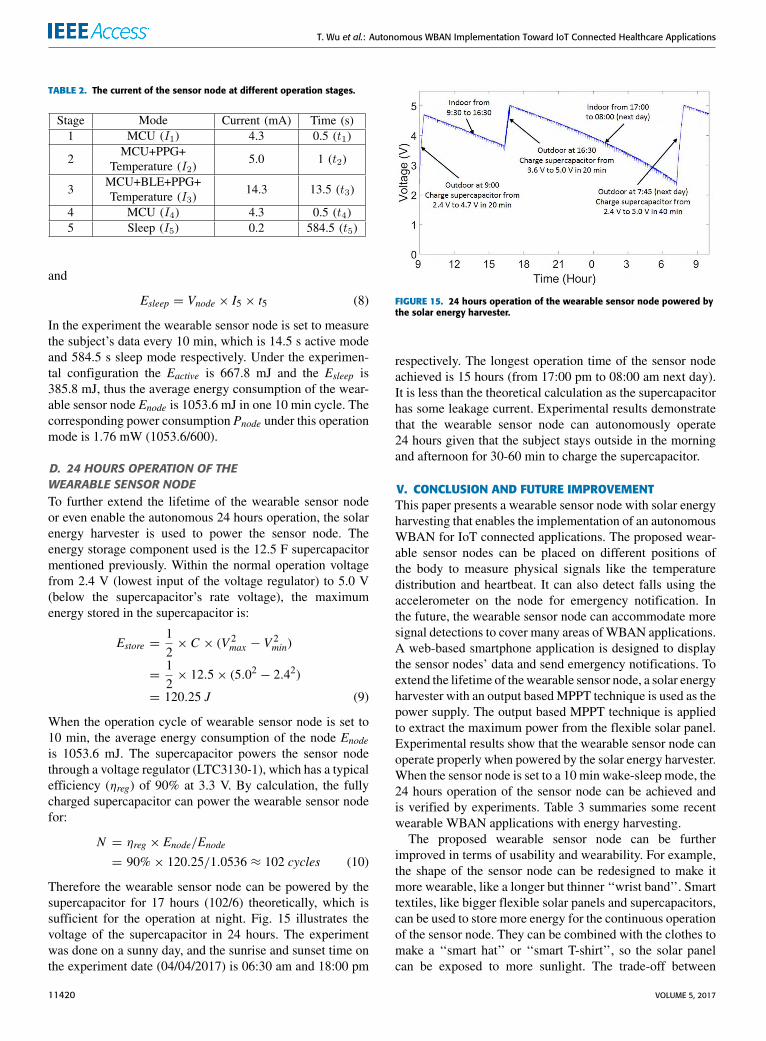
Therefore the wearable sensor node can be powered by thesupercapacitor for 17 hours (102/6) theoretically, which issufficient for the operation at night. Fig. 15 illustrates thevoltage of the supercapacitor in 24 hours. The experimentwas done on a sunny day, and the sunrise and sunset time onthe experiment date (04/04/2017) is 06:30 am and 18:00 pm
FIGURE 15. 24 hours operation of the wearable sensor node powered bythe solar energy harvester.
respectively. The longest operation time of the sensor nodeachieved is 15 hours (from 17:00 pm to 08:00 am next day).It is less than the theoretical calculation as the supercapacitorhas some leakage current. Experimental results demonstratethat the wearable sensor node can autonomously operate24 hours given that the subject stays outside in the morningand afternoon for 30-60 min to charge the supercapacitor.
V. CONCLUSION AND FUTURE IMPROVEMENTThis paper presents a wearable sensor node with solar energyharvesting that enables the implementation of an autonomousWBAN for IoT connected applications. The proposed wear-able sensor nodes can be placed on different positions ofthe body to measure physical signals like the temperaturedistribution and heartbeat. It can also detect falls using theaccelerometer on the node for emergency notification. Inthe future, the wearable sensor node can accommodate moresignal detections to cover many areas ofWBAN applications.A web-based smartphone application is designed to displaythe sensor nodes’ data and send emergency notifications. Toextend the lifetime of thewearable sensor node, a solar energyharvester with an output basedMPPT technique is used as thepower supply. The output based MPPT technique is appliedto extract the maximum power from the flexible solar panel.Experimental results show that the wearable sensor node canoperate properly when powered by the solar energy harvester.When the sensor node is set to a 10 min wake-sleep mode, the24 hours operation of the sensor node can be achieved andis verified by experiments. Table 3 summaries some recentwearable WBAN applications with energy harvesting.
The proposed wearable sensor node can be furtherimproved in terms of usability and wearability. For example,the shape of the sensor node can be redesigned to make itmore wearable, like a longer but thinner ‘‘wrist band’’. Smarttextiles, like bigger flexible solar panels and supercapacitors,can be used to store more energy for the continuous operationof the sensor node. They can be combined with the clothes tomake a ‘‘smart hat’’ or ‘‘smart T-shirt’’, so the solar panelcan be exposed to more sunlight. The trade-off between
11420 VOLUME 5, 2017

T. Wu et al.: Autonomous WBAN Implementation Toward IoT Connected Healthcare Applications
TABLE 3. Comparisons of wearable body area network applications with energy harvesting.
the positions of the solar panel for the exposure to sunlightand the positions of the sensor node for the accurate bodydata measurement will be studied. More sensors for the vitalsignals of the human body can be integrated with the sensornode, like ECG and EMG. In the future, a secondary batterymay also be used as the backup energy storage in case of badweather conditions.
REFERENCES[1] G. Fortino and P. Trunfio, Internet of Things Based On Smart Objects:
Technology, Middleware And Applications. Cham, Switzerland: Springer,2014.
[2] I. Lee and K. Lee, ‘‘The Internet of Things (IoT): Applications, invest-ments, and challenges for enterprises,’’ Bus. Horizons, vol. 58, no. 4,pp. 431–440, 2015.
[3] F. Cicirelli, G. Fortino, A. Giordano, A. Guerrieri, G. Spezzano, andA. Vinci, ‘‘On the design of smart homes: A framework for activityrecognition in home environment,’’ J. Med. Syst., vol. 40, no. 9, pp. 1–17,2016.
[4] P. Gope and T. Hwang, ‘‘BSN-care: A secure IoT-based modern healthcaresystem using body sensor network,’’ IEEE Sensors J., vol. 16, no. 5,pp. 1368–1376, May 2016.
[5] E. Jovanov and A.Milenkovic, ‘‘Body area networks for ubiquitous health-care applications: Opportunities and challenges,’’ J. Med. Syst., vol. 35,no. 5, pp. 1245–1254, 2011.
[6] R. Gravina, P. Alinia, H. Ghasemzadeh, and G. Fortino, ‘‘Multi-sensorfusion in body sensor networks: State-of-the-art and research challenges,’’Inf. Fusion, vol. 35, pp. 68–80, 2017.
[7] C. C. Poon, B. P. Lo, M. R. Yuce, A. Alomainy, and Y. Hao, ‘‘Bodysensor networks: In the era of big data and beyond,’’ IEEE Rev.Biomed. Eng., vol. 8, no. 1, pp. 4–16, Apr. 2015. [Online]. Available:http://ieeexplore.ieee.org/abstract/document/7096962/
[8] M. R. Yuce, ‘‘Implementation of wireless body area networks for health-care systems,’’ Sens. Actuators A, Phys., vol. 162, no. 1, pp. 116–129, 2010.
[9] G. Fortino, G. Di Fatta, M. Pathan, and A. V. Vasilakos, ‘‘Cloud-assistedbody area networks: State-of-the-art and future challenges,’’ WirelessNetw., vol. 20, no. 7, pp. 1925–1938, 2014.
[10] G. Aloi et al., ‘‘Enabling IoT interoperability through opportunisticsmartphone-based mobile gateways,’’ J. Netw. Comput. Appl., vol. 81,pp. 74–84, Mar. 2017.
[11] M. M. Hassan, K. Lin, X. Yue, and J. Wan, ‘‘A multimedia healthcaredata sharing approach through cloud-based body area network,’’ FutureGenerat. Comput. Syst., vol. 66, pp. 48–58, Jan. 2017.
[12] K. Sonoda et al., ‘‘Wearable photoplethysmographic sensor system withPSOC microcontroller,’’ Int. J. Intell. Comput. Med. Sci. Image Process.,vol. 5, no. 1, pp. 45–55, 2013.
[13] Y. H. Kwak, W. Kim, K. B. Park, K. Kim, and S. Seo, ‘‘Flexible heartbeatsensor for wearable device,’’ Biosens. Bioelectron., vol. 94, pp. 250–255,Aug. 2017.
[14] C. Vogt et al., ‘‘A wearable bluetooth le sensor for patient monitor-ing during mri scans,’’ in Proc. 38th Annu. Int. Conf. Eng. Med. Biol.Soc. (EMBC), 2016, pp. 4975–4978.
[15] C. Seeger, K. van Laerhoven, and A. Buchmann, ‘‘MyHealthAssis-tant: An event-driven middleware for multiple medical applications ona smartphone-mediated body sensor network,’’ IEEE J. Biomed. HealthInformat., vol. 19, no. 2, pp. 752–760, Mar. 2015.
[16] T. J. Voss, V. Subbian, and F. R. Beyette, ‘‘Feasibility of energy harvestingtechniques for wearable medical devices,’’ in Proc. 36th Annu. Int. Conf.IEEE Eng. Med. Biol. Soc. (EMBC), Aug. 2014, pp. 626–629.
[17] W. Y. Toh, Y. K. Tan, W. S. Koh, and L. Siek, ‘‘Autonomous wearablesensor nodes with flexible energy harvesting,’’ IEEE Sensors J., vol. 14,no. 7, pp. 2299–2306, Jul. 2014.
[18] R. Hamid and M. R. Yuce, ‘‘A wearable energy harvester unit using piezo-electricŰelectromagnetic hybrid technique,’’ Sens. Actuators A, Phys.,vol. 257, pp. 198–207, Apr. 2017.
[19] M. Magno et al., ‘‘InfiniTime: Multi-sensor wearable bracelet withhuman body harvesting,’’ Sustain. Comput., Inf. Syst., vol. 11, pp. 38–49,Sep. 2016.
[20] A. Dionisi, D. Marioli, E. Sardini, and M. Serpelloni, ‘‘Autonomouswearable system for vital signs measurement with energy-harvestingmodule,’’ IEEE Trans. Instrum. Meas., vol. 65, no. 6, pp. 1423–1434,Jun. 2016.
[21] T. V. Tran andW.-Y. Chung, ‘‘High-efficient energy harvester with flexiblesolar panel for a wearable sensor device,’’ IEEE Sensors J., vol. 16, no. 24,pp. 9021–9028, Dec. 2016.
[22] T. Wu, M. S. Arefin, J.-M. Redoute, and M. R. Yuce, ‘‘A solar energyharvester with an improved mppt circuit for wearable iot,’’ in Proc.11th EAI Int. Conf. Body Area Netw. (Bodynets), Turin, Italy, 2016,pp. 166–170.
[23] F. Wu, C. Rüdiger, and M. R. Yuce, ‘‘Real-time performance of a self-powered environmental iot sensor network system,’’ Sensors, vol. 17, no. 2,pp. 1–14, 2017.
VOLUME 5, 2017 11421

T. Wu et al.: Autonomous WBAN Implementation Toward IoT Connected Healthcare Applications
[24] D. Sera, R. Teodorescu, and P. Rodriguez, ‘‘PV panel model basedon datasheet values,’’ in Proc. IEEE Int. Symp. Ind. Electron. (ISIE),Jun. 2007, pp. 2392–2396.
[25] P. Bhatnagar and R. Nema, ‘‘Maximum power point tracking controltechniques: State-of-the-art in photovoltaic applications,’’ Renew. Sustain.Energy Rev., vol. 23, pp. 224–241, Jul. 2013.
[26] S. E. Babaa, M. Armstrong, and V. Pickert, ‘‘Overview of maximum powerpoint tracking control methods for PV systems,’’ J. Power Energy Eng.,vol. 2, no. 8, 2014, Art. no. 49283.
[27] N. Femia, G. Petrone, G. Spagnuolo, and M. Vitelli, ‘‘A technique forimproving P&O MPPT performances of double-stage grid-connectedphotovoltaic systems,’’ IEEE Trans. Ind. Electron., vol. 56, no. 11,pp. 4473–4482, Nov. 2009.
[28] Y. Wang et al., ‘‘Storage-less and converter-less photovoltaic energy har-vesting with maximum power point tracking for Internet of Things,’’IEEE Trans. Comput.-Aided Design Integr., vol. 35, no. 2, pp. 173–186,Feb. 2016.
[29] A. Frezzetti, S. Manfredi, and A. Suardi, ‘‘Adaptive FOCV-based controlscheme to improve the mpp tracking performance: An experimental vali-dation,’’ IFAC Proc. Vols., vol. 47, no. 3, pp. 4967–4971, 2014.
[30] T. Wu, M. S. Arefin, D. Shmilovitz, J.-M. Redoute, andM. R. Yuce, ‘‘A flexible and wearable energy harvester with an efficientand fast-converging analog MPPT,’’ in Proc. 12th Biomed. Circuits Syst.Conf. (BioCAS), 2016, pp. 336–339.
TAIYANG WU (S’16) received the B.E. degreefrom Southeast University, Nanjing, China, in2014. He is currently pursuing the Ph.D. degree inelectrical and computer systems engineering withMonash University. His main areas of researchinterest are energy harvesting, wireless sensor net-work, and IoT connected applications.
FAN WU (S’17) received the B.E. degree fromMonash University in 2015, where he is currentlypursuing the Ph.D. degree in electrical and com-puter systems engineering. He was a ResearchAssistant with the Engineering Department from2015 to 2017. His main areas of research interestare wireless sensor network, energy harvesting,and IoT innovations.
JEAN-MICHEL REDOUTÉ (M’09–SM’12) rec-eived the M.S. degree in electronics from the Uni-versity College of Antwerp, Belgium, in 1998, theM.Eng. degree in electrical engineering from theUniversity of Brussels, Belgium, in 2001, andthe Ph.D. degree from the University of Leuven in2009. His Ph.D. entitled Design of EMI resistinganalog integrated circuits. In 2001, he was withAlcatel Bell, Antwerp, where he was involved inthe design of analog microelectronic circuits for
telecommunications systems. In 2005, he joined ESAT-MICAS Laborato-ries, University of Leuven, as a Ph.D. Research Assistant. In 2009, he waswith the Berkeley Wireless Research Center, University of California atBerkeley, as a Post-Doctoral Scholar. In 2010, he joined Monash Universityas a Senior Lecturer. His research interests include mixed-signal integratedcircuit design, electromagnetic compatibility, biomedical (integrated andnon-integrated) circuit design, and radio-frequency integrated circuit design.
MEHMET RASIT YUCE (S’01–M’05–SM’10)received the M.S. degree in electrical and com-puter engineering from the University of Florida,Gainesville, FL, in 2001, and the Ph.D. degree inelectrical and computer engineering from NorthCarolina State University, Raleigh, NC, in 2004.He was a Post-Doctoral Researcher with the Elec-trical Engineering Department, University of Cali-fornia at Santa Cruz, in 2005. He was an AcademicMember with the School of Electrical Engineering
and Computer Science, University of Newcastle, NSW, Australia, until 2011.In 2011, he joined Monash University, Australia, where he is currently anAssociate Professor with the Department of Electrical and Computer Sys-tems Engineering. He has authored over booksWireless Body Area Networkspublished in 2011 and Ultra-Wideband and 60 GHz Communications forBiomedical Applications published in 2013. His research interests includewearable devices, Internet-of-Things for healthcare, wireless implantabletelemetry, wireless body area network, bio-sensors, and integrated circuittechnology dealing with digital, analog, and radio frequency circuit designsfor wireless, biomedical, and RF applications. He has authored over 150technical articles in the above areas and received the NASA Group Achieve-ment Award in 2007 for developing an SOI transceiver. He received theBest Journal Paper Award in 2014 from the IEEE Microwave Theory andTechniques Society. He received the Research Excellence Award in theFaculty of Engineering and Built Environment, University of Newcastle, in2010. He is a Topical Editor of the IEEE SENSORS Journal and a Guest Editorof the IEEE JOURNAL OF BIOMEDICAL AND HEALTH INFORMATICS in 2015.
11422 VOLUME 5, 2017