an automatic code generation for self-healing
TRANSCRIPT
JOURNAL OF INFORMATION SCIENCE AND ENGINEERING 25, 1753-1781 (2009)
1753
An Automatic Code Generation for Self-Healing*
JEONGMIN PARK, HYUNSANG YOUN AND EUNSEOK LEE
School of Information and Communication Engineering Sungkyunkwan University
Suwon 400-746, South Korea
The overall goal of this research is to improve self-healing development environ-
ments to facilitate self-managing capabilities such as self-healing. Self-healing is an ap-proach to evaluating constraints defined in a target system and to apply an appropriate strategy when the constraints have been violated. Much attention has recently been fo-cused on self-healing ability that recognizes problems arising in a target system. How-ever, in order to generate code for self-healing, most of the existing approaches show that self-healing development environments need much effort and time to analyze and model constraints. Hence, for self-healing, this paper proposes an automated code generation approach to determine problems arising in external and internal system environments. The approach proposes: (1) Specifying the target system through the models created in the design phase of target system. (2) Automatically creating constraints for the external and internal system environment by using the specified contents. (3) Deriving a depend-ency model of a component based on the created internal state rule. (4) Translating the constraints and dependency model into code evaluating behaviors of the target system, and the determining problem level. (5) Monitoring an internal and external status of sys-tem based on the level of problem determination, and applying a self-healing strategy when detecting an abnormal state caused in the target system. As proof of the approach, we used a video conference system and E-Commerce System for the case study. The ex-perimental results show that it achieves reducing the efforts required for developers of self-healing systems to analyze the target system and resolving abnormal behavior of the target system in regard to both external and internal problem. Keywords: code generation, autonomic computing, self-healing, external state, internal state, error detection
1. INTRODUCTION
In recent years, research of self-healing has been given a considerable attention to construct target system reliable. Self-healing is an approach to detect improper operation of software, and then to initiate corrective action without disrupting users [1]. It is con-cerned with the ability of the system to automatically recover from faults.
The complexity of the software execution environment is increasing tremendously. Software should be able to execute even with more complexity particularly in ubiquitous computing environments. A large number of environmental computing entities can have innumerable interactions with each other. Hence, it is difficult for software to execute robustly. This new computing environment poses new challenges for software develop-ers. When computer systems operate abnormally, detecting and resolving the problem requires much time and effort. Therefore, software should adapt without human interven-tion to achieve a self-healing ability. Received January 9, 2008; revised August 12 & October 8 & November 21, 2008; accepted December 11, 2008. Communicated by Jonathan Lee. * This paper was supported by Faculty Research Fund, Sungkyunkwan University, 2008.
JEONGMIN PARK, HYUNSANG YOUN AND EUNSEOK LEE
1754
Several approaches have been proposed to develop self-healing system, including component-based, Architecture-based, and log-based approaches. They have been de-veloped to either adapt software systems at the external resource environment or to make the systems more reliable as internal components within component-based systems. These developments provide full or partial services of the systems continuously even while the systems evolve or encounter anomalies.
However, many of these approaches show that developers of self-healing systems have to overcome many obstacles in order to analyze the target system. Namely, the ex-isting mechanisms showed that developers or analysts developing self-healing software need much effort and time so that they analyze the target system and model constraints for generating self-healing code. So far, research on resolving theses problem is still in its early state.
To implement self-healing to cope with external and internal abnormal states in the system requires much effort. For example, they have to generate the constraint rules to monitor an external resource state of target system, and the state rule to monitor an in-ternal state of a component. The ability of the developer to understand the target system is crucial. Accordingly, using UML artifacts generated at the design phase of the soft-ware development can be used to endow the target system’s self-healing ability. Thus it is possible to reduce self-healing developer’s effort and time to analyze the system. Consequently, in this paper, we propose an automatic code generation for self-healing to resolve the problems mentioned above as follows.
Step 1: The use of UML models created at design phase (specifying the target system). Step 2: Automatically creating constraints for external and internal system environment
based on the UML models. Step 3: Deriving a dependency model of a component based on internal state rule. Step 4: Translating the constraints and dependency model into code evaluating behav-
iors of the target system, and determining problem level. Step 5: Monitoring the internal and external status of system based on the level of prob-
lem determination, and applying a self-healing strategy when detecting an ab-normal state in the target system. If an abnormal operation occurs, the previ-ously planed reconfiguration strategy can be applied [2].
As proof of the approach, we used a video conference system. The experimental results show that it achieves reducing the efforts required for developers of self-healing systems to analyze the target system and resolving abnormal behavior of the target sys-tem in regard to both external and internal problem. This remainder of this paper is or-ganized as follows: Section 2 is devoted to an in-depth analysis of related work. Section 3 describes system architecture. In section 4, we describe an automated approach capsu-lated by the system architecture. Section 5 discusses its implementation and evaluation. Finally, section 6 presents our conclusions.
2. RELATED WORK
With the advent of the ubiquitous computing paradigm, the self-healing approach has been applied to the target system based on context-awareness, calm computing [3]

AN AUTOMATIC CODE GENERATION FOR SELF-HEALING
1755
and autonomic computing [4]. Basic strategies for self-healing adopt tactics such as re-starting the system or replacing the faulty component. Studies show how systems can recover from an abnormal state to a normal state by having an awareness of the external resource environments (CPU, RAM, Bandwidth, etc). There are component-based self- healing frameworks that design additional modules for their ability to generating self- healing at the software design phase in order to reinforce reliability of the target system. In this section, we describe these forms of self-healing approaches, and analyze their features and weaknesses. 2.1 Architecture-based Self-healing Approaches
Architecture-based self-healing approaches [2, 5, 6] use the architectural model as a basis for system reconfiguration. They have a view of the external environment to moni-tor, analyze, and reconfigure the target system. A set of probes are deployed in the target system or physical environment and announce aspects of the actual system by means of a probe bus. The data are monitored by a gauge. Gauges translate and analyze data by searching logical events mapped to physical events using a structural model. The control layer monitors whether an action succeeded or not by logging good, suspicious, and bad events. Effectors interact with the target system to tune and restart the system based on the adaptation plan. These proposed approaches model resource environments and proc-esses based on an external view founded on ADL (Architecture Description Language). Architecture-based self-healing approaches for external environments have benefits and drawbacks as follows. • It is sufficient to generate probes that monitor the target system based on an external
architecture model. They need not to modify target system based on information col-lected by probes about the external resource environments.
• They support self-healing application development without internal information on target system. Some of external self-healing approaches are well attention.
• When developing self-healing software without internal information on target system, developers and analysts, they cannot but generate self-healing code not to affect the original system. This is performance based self-healing approach. Thus, it is difficult to determine the internal state of the component because the approach focuses on per-formance of the external environment. It is also difficult to develop a variety of self- healing strategies without internal information on target system.
2.2 Component-based Self-healing
Component-based self-healing [7, 8] focused on the internal status of software by adding the capability that supports self-healing at the design phase to make software. It separately designed the service and healing layers in the component. The approach mod-eled the state of normal actions of the service layer in a component. If an anomaly is de-tected, it would restart, initialize, reconfigure the system by using blocking and freezing. Component-based self-healing systems have advantages and disadvantages as listed be-low.

JEONGMIN PARK, HYUNSANG YOUN AND EUNSEOK LEE
1756
• They are able to reconfigure components in the service layer in component-based ar-chitecture through the state model that model behaviors of tasks in the service layer. Also, after reconfiguration, it provides a standard to judge whether or not the compo-nent can perform operations normally
• However, As these focused on events related to internal states, they cannot determine internal status problems due to lack of resource. Hence, it cannot heal resource anoma-lies.
2.3 Log-based Self-healing Log-based self-healing approaches [9, 10] suggest self-healing of the system by auto- correcting event logs generated from various types of software (webserver, database sys-tem, etc.). Log-based self-healing systems analyze errors about the internal status of tar-get system by converting a log event to a common base event. The logs are generated based on a common format and are analyzed by an autonomic manager. The healing sys-tem performs self-healing strategies when encountering anomalies through a symptom service and policy engine. The benefits and drawbacks of this approach are listed below. • It is useful to search for related problems based on log events provided by the system
when an error event is logged. It also can easily restructure a database and be useful for bottom-up analysis because the contents of the log are recorded at runtime.
• Monitoring methods have difficulty to detect the source of the problem if the event has yet to be logged. Because it focuses on problems after the event, it is difficult to model constraints for monitoring, analyzing, and healing based on the internal view of system if the event is unlogged. Additional effort is needed to determine the level of problem determination in the target system. It is difficult to analyze whether the problem caused by one component influences another one from only the contents of the log.
A strict definition of reliability relates the system implementation to its specification.
That is, the system is behaving reliably if its behaviour is consistent with that defined in the specification. System failures are inevitable, but the disruption caused by failure can be minimized if the system can be repaired. In order for that to happen, it must be possi-ble to diagnose the problem, access the component that has failed and make changes to fix that component. However, Self-healing in software is enhanced when the organization using the system has access to source code and has the skills to make changes to it [11].
Unfortunately, this is becoming increasingly uncommon as we move towards sys-tem development using third-party, black-box components. Therefore, this paper assumes that the software developer and the self-healing software developer are different. The self- healing software developer has a high burden to analyze the target system as follows:
• It has burden to analyze the target system because it is necessary to analyze constraints
for detecting the internal and external statuses of the target system. • It has burden to analyze the dependence between components related to the abnormally
functioning component.
The aim of this paper is to explore the way that automate generating self-healing

AN AUTOMATIC CODE GENERATION FOR SELF-HEALING
1757
code by automatically analyzing the target system and modeling constraints based on UML artifacts generated at the design phase. Because UML artifacts that we use have internal information on target system, it is possible to determine the internal state of the component. Also, various self-healing strategies are able to be generated. However, here we shall not polemicize on self-healing strategies. This paper is intended that this will satisfy the external and internal environments of the target system for solving common vulnerabilities in the software architecture. We describe the details in the next section.
3. OVERVIEW OF CODE GENERATION ARCHITECTURE
In this section, we describe the requirements and software architecture for self-heal- ing systems that can adapt to changes in external and internal situations. These are based on the UML [12] models created at design time. 3.1 Requirement for External Environment
Components are treated as black boxes in a distributed environment. Problems in the external environment can abound. Therefore, the requirements of the external envi-ronment should identify problems of running the environmental computing resource of the target system or interactions among the computing objects. 3.2 Requirement for Internal State
Requirements for internal environment should identify the problems that occur in the internal of components or classes that compose the software system. In order to sat-isfy these requirements from the internal environment, the following factors should be satisfied. First, in order for problem determination to be successful design models of the target system should be created at design time. Second, the internal environmental rule model should be generated automatically. This enables components or classes to detect internal behaviors based on the specified design model. Third, dependency analysis should be implemented to decide whether the abnormal behaviors of specific components affect other components. Four, problem determination levels of components or classes should be determined automatically via the generated internal rule model and depend-ency analysis. Finally, monitoring and healing should be applied to the internal situation of the target system based on problem determination levels and the problems of compo-nents or classes when there are violations of internal rules. 3.3 Self-Healing Software Architecture
In this paper, in order to self-heal the target system, we use the UML design model generated by application developers at design time. The UML design models can be clas-sified into external environment models and internal environment models. External en-vironment models use deployment models and internal environment models use class models, sequence models, and activity models. Although there are difficulties in sepa-rately generating constraints for solving external or internal problems of the target sys-
JEONGMIN PARK, HYUNSANG YOUN AND EUNSEOK LEE
1758
tem in existing researches, this paper uses the UML design models, constraints, depend-ency conditions and problem determination levels of external environment and internal situation that will to be generated automatically.
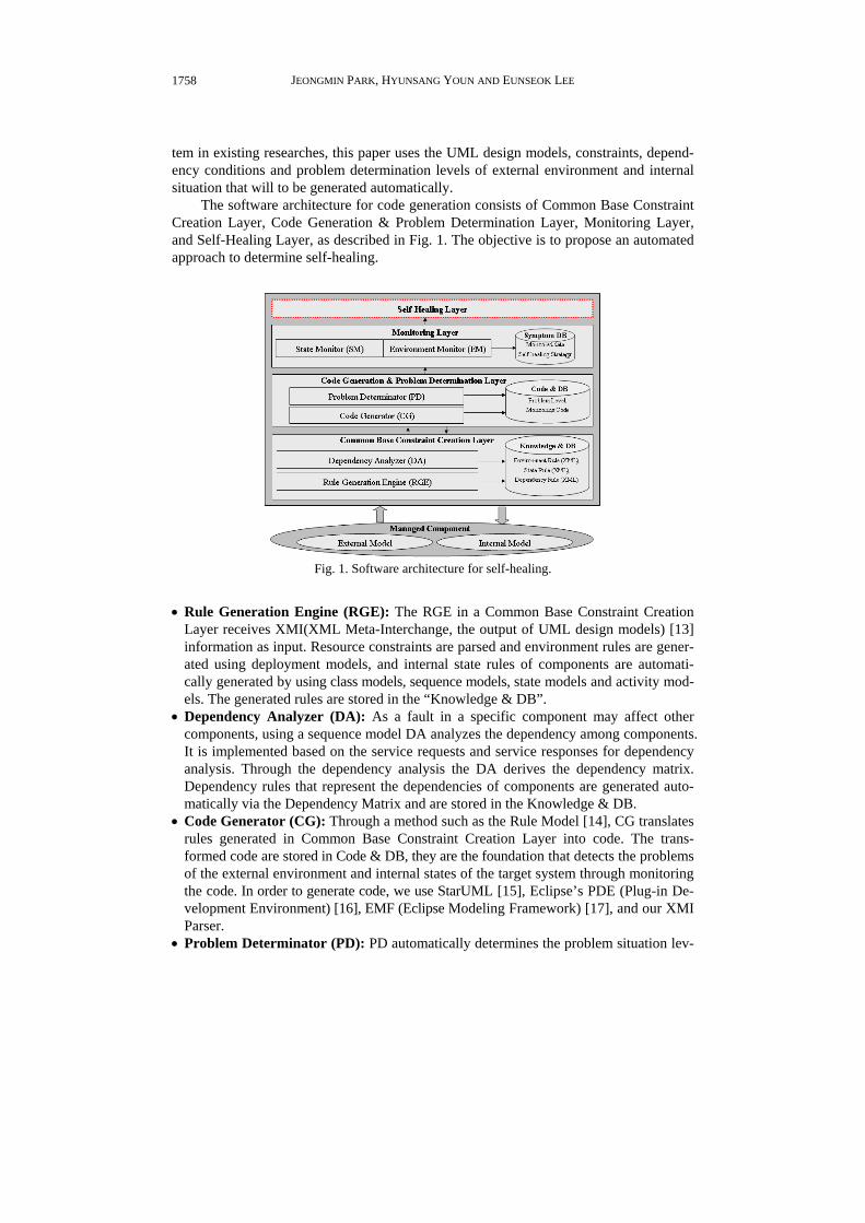
The software architecture for code generation consists of Common Base Constraint Creation Layer, Code Generation & Problem Determination Layer, Monitoring Layer, and Self-Healing Layer, as described in Fig. 1. The objective is to propose an automated approach to determine self-healing.
Fig. 1. Software architecture for self-healing.
• Rule Generation Engine (RGE): The RGE in a Common Base Constraint Creation
Layer receives XMI(XML Meta-Interchange, the output of UML design models) [13] information as input. Resource constraints are parsed and environment rules are gener-ated using deployment models, and internal state rules of components are automati-cally generated by using class models, sequence models, state models and activity mod-els. The generated rules are stored in the “Knowledge & DB”.
• Dependency Analyzer (DA): As a fault in a specific component may affect other components, using a sequence model DA analyzes the dependency among components. It is implemented based on the service requests and service responses for dependency analysis. Through the dependency analysis the DA derives the dependency matrix. Dependency rules that represent the dependencies of components are generated auto-matically via the Dependency Matrix and are stored in the Knowledge & DB.
• Code Generator (CG): Through a method such as the Rule Model [14], CG translates rules generated in Common Base Constraint Creation Layer into code. The trans-formed code are stored in Code & DB, they are the foundation that detects the problems of the external environment and internal states of the target system through monitoring the code. In order to generate code, we use StarUML [15], Eclipse’s PDE (Plug-in De-velopment Environment) [16], EMF (Eclipse Modeling Framework) [17], and our XMI Parser.
• Problem Determinator (PD): PD automatically determines the problem situation lev-
AN AUTOMATIC CODE GENERATION FOR SELF-HEALING
1759
els of the collected external and internal monitoring data. First, situation levels for the external resource environment automatically determine problem levels of the external environment in the application domain. Levels may be such as “normal”, “abnormal”, “panic”. Second, internal state levels have situation lists of each component and auto-matically determine situation problem levels of components such as “normal”, “error”, “panic” according to the state success rates that the components satisfy. Finally, the determined external, internal problem determination levels are stored in Symptom DB.
• Environment Monitor (EM): EM monitors resource constraints that are specified in deployment models and compares the monitored information and translated external environment rules to estimate whether there are violations of constraints.
• State Monitor (SM): SM monitors the internal states of components that are specified in state models. Violations of constraints are estimated through comparisons between the monitored information and the transformed internal situation rules. Namely, it judges that whether or not the state one of each component in turn is satisfactory.
• Self-Healing Layer: This layer will be extended in future work, the layer will generate and make strategies and priorities based on problem determination levels stored in the Symptom DB. The Administrator will intervene when generating tactics for self-heal- ing. In this paper, in order to solve problems arising in the target system we apply a reconfiguration strategy defined in advance. For example, components accessing the server will be reconfigured when the resource environment of the server is changed into an abnormal state. Components will be reconfigured and reinstalled if problems arise inside the client.
4. CODE GENERATION PROCESS FOR SELF-HEALING
In this section, we introduce code generation process that is encapsulated in self- healing software architecture for determining problems. The introduced code generation process that is included in self-healing software architecture consists of the following phases as described in Fig. 2. First, the software developer of the target system specifies UML design models. Second, the rule generation engine executes the process of gener-ating external environment rules and internal situation rules, and the dependency ana-lyzer executes the process of generating Dependency Matrix and dependency rules. Third, the code generator executes the process of transforming the rules generated in the former phase to code, and the problem determinator executes the automation of problem deter-mination levels. Finally, resource and state gauge the external resource environment and internal state environment. We will explain each phase of the whole process in detail in the next sub-section.
4.1 Step 1: Target System Specification via UML Design Model
Modeling the specific viewpoint for managing the target system is crucial. Thus, we use the UML model information from the design phase to capture the external environ-ment states and internal component states of the target system. In order to capture the external environment states, we use the deployment models that specify the external en-vironment of the target system in the application domain when designing software. The

JEONGMIN PARK, HYUNSANG YOUN AND EUNSEOK LEE
1760
Fig. 2. Code generation process for self-healing (5-steps).
target systems in specific application domains do not independently execute, but interact with each other via software in the run-time environment. For instance, servlet ‘A’ and the database in a web application server can be illustrated. The database can interact with servlet ‘A’ depending on the SQL processing agent. The deployment model that models the physical resource environment of such a target system can specify the constraints of the resource environment related to the application domain in advance. In order to satisfy the non-functional requirements, resource utilization can be captured based on the re-source constraint models specified in the deployment models.
This paper is based on the class model, sequence model, state model, and activity model, specified when designing the system to capture internal states of the target system. Class models are used in order to recognize relative components or classes and to recog-nize the executed operations of components. Sequence models are used to examine the dependency relations among components as they can recognize interactions between components or objects. State models are used to identify the internal state variations of each component, and activity models are used to recognize behaviors that should be sat-isfied when transferring between states for each component. UML design models can express functional requirements of software from various points of view. Thus, they are great support in analyzing internal states of the target system. The viewpoint of this pa-per is that software developers of the target system should use design models as initial information for self-healing. This will allow a focus on the system to self-diagnose prob-lems when software errors occur. 4.2 Step 2: External and Internal Constraints Generation of Target System
In the target system constraints generation stage, the Rule Generation Engine (RGE) generates the external and internal constraints. RGE uses a similar approach to Wang’s XML Rule Model [14]. As input information of RGE, the RGE receives XMI (XML Meta- Interchange, the output of UML design models) information. The UML tool designing

AN AUTOMATIC CODE GENERATION FOR SELF-HEALING
1761
Fig. 3. Architecture of rule generation engine.
Fig. 4. Deployment diagram for external environment rule.
UML Model can export the XMI information. Namely, RGE’s requiring syntax of UML Model is the XMI information that is automatically exported by UML tool. Fig. 3 shows architecture of RGE. Most important key module of RGE is XMI Parser.
UML deployment model (Fig. 4) is used for generating the external constraint rules. The deployment model, which expresses the constraint conditions of software that is related to the application domain, is used and classified into two categories of resource types. First, it recognizes the external environment that exists in the application domain (For example, DBMS, Web Server etc.). Second, factors such as RAM, CPU, bandwidth, number of clients, storage usage are recognized. XMI Parser parses XMI information (the left side of Fig. 5) generated in the deployment model and automatically generates the environment rule that expresses the thresholds of resource utilization as XML (the right side of Fig. 5) according to two categories. Actually, implementing RGE requires much effort to extract essential information since a large amount of XMI information is gener-ated by design models. Thus, in order to effectively develop RGE, static analysis about its information may need to be required.

JEONGMIN PARK, HYUNSANG YOUN AND EUNSEOK LEE
1762
Fig. 5. Constraint rule model based on XMI [14] and XML rule [15].
Fig. 6. Extracted information for internal state.
In order to generate constraints of the internal state, the required information is iden-
tified through design models. Design models like the class model, sequence model, state model and activity model are used. XMI information from each one is used and the re-quired information is recognized (Fig. 6). Participant classes are recognized by the class

AN AUTOMATIC CODE GENERATION FOR SELF-HEALING
1763
model and related operations are recognized. The sequence model recognizes interactions about operation requests and responses of each class. The states that each class holds are recognized via the state model.
As each class may have several states, UML design tools such as “StarUML” can support recognizing activities that satisfy specific states of components (Fig. 7). In this paper, the activity model is composed of several actions. This assumes that it is designed by actual function names. Recognizing the activities of one state can be supported by the UML design tool. XMI information, which is the output file generated from the design models, is extracted. RGE uses it to extract information that is required by each design model, and generates the internal state route rules such as shown in Fig. 8.
Fig. 7. Activity model for satisfying each state.
Fig. 8. (a) Rule for internal state.

JEONGMIN PARK, HYUNSANG YOUN AND EUNSEOK LEE
1764
Fig. 8. (b) An example of a triggerless state transition.
As described in [20]. There are two state transitions as follows:
• Trigger state transition: it can indicate an event that causes a transition to occur (a trig-
ger event) and the computation (the action) that executes and makes the state change happen. We are based on trigger state transition. On the other hand, most state transi-tions may correspond to an operation.
• Triggerless state transition: sometimes a transition occurs because a state completes an activity (rather than because of an event). This type of transition is called a triggerless transition.
The UML state diagram presents the states an object can be in along with transitions
between the states and show the starting point and endpoint of a sequence of state changes. Three frequently used categories of activities are entry activity (what happens when the system enters the state, we call it starting point), exit activity (what happens when the system leaves the state, we call it endpoint), and do activity (what happens while the sys-tem is in the state).
If the state transition in a UML state diagram may not correspond to an operation. In such case, we may deal with it based on dependency between exit activity and entry activity. For example, Fig. 8 (b) show a triggerless state transition. A fax machine’s states have activities. When it is in faxing state, the fax machine engages in the activities of adding a datestamp (do activity) and timestamp (do activity) to the fax and adding its phone number (do activity) and the name of its owner (do activity). In other activities in this state, the machine pulls the pages through (do activity), paginates the fax (do activ-ity), and completes the transmission (exit activity). While it is in the idle state, the fax machine presents the date and time (do activity) on a display. In here, a fax machine’s exit activity is an idle-state’s entry activity. Also idle’s exit activity is a fax machine’s entry activity. By analyzing the dependency between exit activity and entry activity, we may present the state transition that may not correspond to an operation.
AN AUTOMATIC CODE GENERATION FOR SELF-HEALING
1765
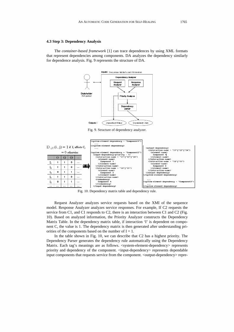
4.3 Step 3: Dependency Analysis
The container-based framework [1] can trace dependences by using XML formats that represent dependencies among components. DA analyzes the dependency similarly for dependence analysis. Fig. 9 represents the structure of DA.
Fig. 9. Structure of dependency analyzer.
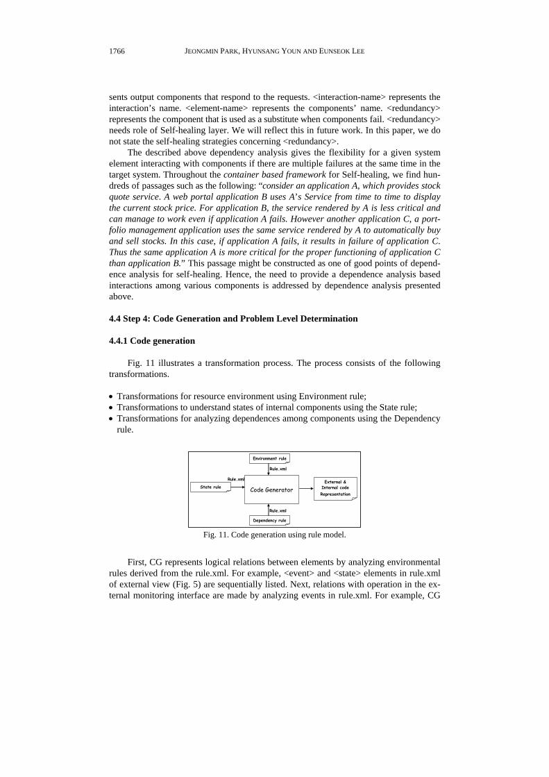
Fig. 10. Dependency matrix table and dependency rule.
Request Analyzer analyzes service requests based on the XMI of the sequence
model. Response Analyzer analyzes service responses. For example, If C2 requests the service from C1, and C1 responds to C2, there is an interaction between C1 and C2 (Fig. 10). Based on analyzed information, the Priority Analyzer constructs the Dependency Matrix Table. In the dependency matrix table, if interaction ‘I’ is dependent on compo-nent C, the value is 1. The dependency matrix is then generated after understanding pri-orities of the components based on the number of I = 1.
In the table shown in Fig. 10, we can describe that C2 has a highest priority. The Dependency Parser generates the dependency rule automatically using the Dependency Matrix. Each tag’s meanings are as follows. <system-element-dependency> represents priority and dependency of the component. <input-dependency> represents dependable input components that requests service from the component. <output-dependency> repre-
JEONGMIN PARK, HYUNSANG YOUN AND EUNSEOK LEE
1766
sents output components that respond to the requests. <interaction-name> represents the interaction’s name. <element-name> represents the components’ name. <redundancy> represents the component that is used as a substitute when components fail. <redundancy> needs role of Self-healing layer. We will reflect this in future work. In this paper, we do not state the self-healing strategies concerning <redundancy>.
The described above dependency analysis gives the flexibility for a given system element interacting with components if there are multiple failures at the same time in the target system. Throughout the container based framework for Self-healing, we find hun-dreds of passages such as the following: “consider an application A, which provides stock quote service. A web portal application B uses A’s Service from time to time to display the current stock price. For application B, the service rendered by A is less critical and can manage to work even if application A fails. However another application C, a port-folio management application uses the same service rendered by A to automatically buy and sell stocks. In this case, if application A fails, it results in failure of application C. Thus the same application A is more critical for the proper functioning of application C than application B.” This passage might be constructed as one of good points of depend-ence analysis for self-healing. Hence, the need to provide a dependence analysis based interactions among various components is addressed by dependence analysis presented above. 4.4 Step 4: Code Generation and Problem Level Determination 4.4.1 Code generation
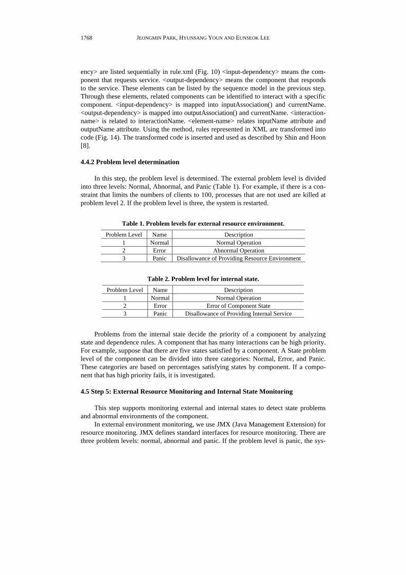
Fig. 11 illustrates a transformation process. The process consists of the following transformations.
• Transformations for resource environment using Environment rule; • Transformations to understand states of internal components using the State rule; • Transformations for analyzing dependences among components using the Dependency
rule.
External & Internal codeRepresentation
Code Generator
Environment rule
State rule
Dependency rule
Rule.xml
Rule.xml
Rule.xml External & Internal codeRepresentation
Code Generator
Environment rule
State rule
Dependency rule
Rule.xml
Rule.xml
Rule.xml
Fig. 11. Code generation using rule model.
First, CG represents logical relations between elements by analyzing environmental
rules derived from the rule.xml. For example, <event> and <state> elements in rule.xml of external view (Fig. 5) are sequentially listed. Next, relations with operation in the ex-ternal monitoring interface are made by analyzing events in rule.xml. For example, CG

AN AUTOMATIC CODE GENERATION FOR SELF-HEALING
1767
/* External code representation, C = Component */ invariant (C.getClientNumber() < 100) && (CPU.available() >= 0.1) && (RAM.available() >= 0.3)) ! -> C.setInstanceNumber(120)
Fig. 12. Code transformation for external resource environment.
/* Internal code representation, C = Component */ // State code representation While (request) { … if (C.getRequest() == “initial request”) { C.currentState + STATE1.START; C.activity = C.getCurrentAction(); C.relationActivity = C.getRelationActivity();
if ((C.activity == false) || (C.relationActivity == false)){ C.currentState == STATE1_FALURE; return C.currentState;
}
if ((C.activity == ture) && (C.relationActivity == ture)){ C.currentState == STATE1_OK; C.nextState == STATE2 return C.currentState;
} }
… }
/* Internal code representation, C = Component */ // Dependency- code representation if (C2.interactionName == “ I1” || “I2” || I4”) { currentName = C2 inputName = C1; outputName = C1;
inputAssociation(currentName, inputName); outputAssociation(currentName, outputName);
} if (C.interactionName == “I3” || “I5”) { currentName = C2 inputName = C3; outputName = C3;
inputAssociation(currentName, inputName); outputAssociation(currentName, outputName);
}
Fig. 13. Code for internal state. Fig. 14. Code for dependence analysis.
maps <event> element to getClientNumber(). This means that if getClientNumber() is bigger than 100, the event occurred. Rules represented by XML are transformed into code as Fig. 12.
Second, CG represents logical relations among elements from rule.xml. For exam-ple, <current-state>, <action> and <next-state> of <request-name> are sequentially listed. In the next step, events in rule.xml are mapped from “operation” to “attribute” in the inter-nal environment’s monitoring interface. For example, <request-name> mapped getRe-quest() of components. <current-state> mapped currentState. <action> is mapped getCur-rentAction(). <next-state> is mapped nextState. Finally, if <related-activity> is mapped get- RelationActivity(). getCurrentAction() and getRelationActivity() return a Boolean value whether or not the expected functions are performed. Rules in XML are transformed into code as in Fig. 13.
Third, CG makes logical relations among elements using rule.xml. This is for code generation in view of dependence analysis. <input-dependency> and <output-depend-
JEONGMIN PARK, HYUNSANG YOUN AND EUNSEOK LEE
1768
ency> are listed sequentially in rule.xml (Fig. 10) <input-dependency> means the com-ponent that requests service. <output-dependency> means the component that responds to the service. These elements can be listed by the sequence model in the previous step. Through these elements, related components can be identified to interact with a specific component. <input-dependency> is mapped into inputAssociation() and currentName. <output-dependency> is mapped into outputAssociation() and currentName. <interaction- name> is related to interactionName. <element-name> relates inputName attribute and outputName attribute. Using the method, rules represented in XML are transformed into code (Fig. 14). The transformed code is inserted and used as described by Shin and Hoon [8]. 4.4.2 Problem level determination
In this step, the problem level is determined. The external problem level is divided into three levels: Normal, Abnormal, and Panic (Table 1). For example, if there is a con-straint that limits the numbers of clients to 100, processes that are not used are killed at problem level 2. If the problem level is three, the system is restarted.
Table 1. Problem levels for external resource environment.
Problem Level Name Description 1 Normal Normal Operation 2 Error Abnormal Operation 3 Panic Disallowance of Providing Resource Environment
Table 2. Problem level for internal state.
Problem Level Name Description 1 Normal Normal Operation 2 Error Error of Component State 3 Panic Disallowance of Providing Internal Service
Problems from the internal state decide the priority of a component by analyzing
state and dependence rules. A component that has many interactions can be high priority. For example, suppose that there are five states satisfied by a component. A State problem level of the component can be divided into three categories: Normal, Error, and Panic. These categories are based on percentages satisfying states by component. If a compo-nent that has high priority fails, it is investigated. 4.5 Step 5: External Resource Monitoring and Internal State Monitoring
This step supports monitoring external and internal states to detect state problems and abnormal environments of the component.
In external environment monitoring, we use JMX (Java Management Extension) for resource monitoring. JMX defines standard interfaces for resource monitoring. There are three problem levels: normal, abnormal and panic. If the problem level is panic, the sys-

AN AUTOMATIC CODE GENERATION FOR SELF-HEALING
1769
tem notifies the administrator and is rebooted. If the problem level is abnormal, we can kill unused processes or redirect service to another server.
In internal state monitoring, the states that a component has are monitored. First of all, the component that has a higher priority is monitored, codes generated for monitor-ing check states of component. If a component state is “error”, then the component is blocked, initialized, and substituted. If a component state is “panic”, then the component can be restarted after notifying the administrator because it cannot provide any services. In this paper, we do not focus on healing strategies and priority of strategies.
5. IMPLEMENTATION AND EVALUATION
We introduce our approach based on video conference system and E-commerce sys-tem as the case study. We have developed a simple application for validating for the pro-posed method. 5.1 Configuration Environment of Video Conference System and Actions
A goal of the video conference system, for which the basic design is represented by UML, is to achieve a successful meeting. During the meeting, users transfer some files and should not be interrupted by network problems and so on. Fig. 15 depicts an online company that sells a product. The customer, seller, product designer and AS staff attends a meeting. The video conferencing system configuration environment is as follows:
Fig. 15. Architecture of video conferencing system.
• Clients 1 and 2 use a desktop computer that has CPU 1.0GHz, 512MB and .Net 2.0,
Direct X 8.0 installed. Client 3 uses a PDA that has CPU 400MHz, 64MB. • Mobile Proxy1 has CPU 2.0GHz, 512MB and JDK 1.4 version installed. It has a role
to connect the participants in a video conferencing session rather than as PDA users. Mobile Proxy 2 has the same specification as Mobile Proxy 2. If Mobile Proxy1 has a

JEONGMIN PARK, HYUNSANG YOUN AND EUNSEOK LEE
1770
poor resource environment, it follows a reconfiguration strategy. • Server1 has CPU 2.0GHz, 1GB and JDK 1.4 installed. It is used to control the session
information of clients, and perform the multicast. Server2 has the same specification as Server1. If Server1 has a poor resource environment, it follows a reconfiguration strat-egy.
The video conference system is based on Multicast. Among the connected nodes, the
PC sends images to the server using UDP. The server sends them to other clients through an assigned port number using Multicast. The PC registers its IP to the server. The server notifies UDP the port number that the PC uses and control sessions through the regis-tered IP. Through the Mobile Proxy, the PDA can attend video conferencing that other PCs attend. Each node sends and receives images from the camera, messages for video conferencing, and has a screen to show them to user.
Fig. 16. (a) Abnormal state of video conference system.
S1
S2
S3
Fig. 16. (b) State machine of abnormal status.

AN AUTOMATIC CODE GENERATION FOR SELF-HEALING
1771
Figs. 16 (a) and (b) show that one client has been in an abnormal state during video conferencing.
An abnormal state means the computer and network of the client are overloaded and the client does not send normal images and the overall network speed of the multicast has been low. The proposed approach, which is embedded in the video conferencing system for self-healing, carries out the following actions.
• Based on Rules that are generated automatically by the design model of the video con-
ferencing system, the cause of this problem is diagnosed. It understands that sending images follows these steps: state 1 (sending images from a camera) − state 2 (process-ing transferred data) − state 3 (sending processed data). Based on recognized states, it recognizes the specific actions of each state.
• To understand whether or not a camera sends some images (state 1) it checks the exis-tence of some data that breaks the state rule. If there are no data, it recognizes that the state is normal. The system analyzes data monitored from the part that transfers the data in a suitable format. It recognizes that the opposite client does not understand some data that are being sent (state 3) because an error has occurred processing data from a camera. Because the client’s specific state has been detected as “error”, it car-ries out the reconfiguration strategy. These include such activities as component ini-tialization, component reinstallation, component restart, according to the pre-defined healing policy.
After healing, the abnormal state of the video conference system reverts to the nor-
mal state and the meeting resumes. In the existing approach, if some problems occur, a manager takes care of them and manually reconfigures the software modules. Here the system itself understands these problems and heals them. So it is possible to perform a successful meeting (Figs. 17 (a) and (b)).
Fig. 17. (a) Normal state of video conferencing system after self-healing.

JEONGMIN PARK, HYUNSANG YOUN AND EUNSEOK LEE
1772
Fig. 17. (b) State machine of formal status.
Through this implementation, we verify that the approach proposed in section 4 can
be applied to a video conferencing system. If an abnormal state occurs, existing studies of self-healing mainly utilize a reconfiguration strategy. A self-healing strategy can make repairs suited to the manager’s policies regarding the external environment and internal state.
The proposed approach supports that it can be easy to extract constraint conditions of the external resource environment and the internal state problems of target systems. Based on UML one can link analysis, generate monitoring codes and define the level of problem decision from the design models. The constraint condition is critical to the ac-tions of target systems. Link analysis represents links between components of the target system. Generated code and the level of problem definitions decide whether the opera-tion of the target system is normal through error-checking codes for constraint condition. Table 3 describes comparisons between the proposed approach and the approach of ex-isting studies in self-healing activities.
In the existing approach, self-healing experts for self-healing activities need more time and effort to analyze target system and design self-healing system for setting con-straint condition, dependency analysis, generating codes and setting level of problem decision.
The proposed approach can reduce the effort required to analyze the target system and design the self-healing system by automating constraint conditions, analyzing de-pendency, generating code, setting levels of problem resolution through minimum coop-eration that is achieved with the self-healing expert developer, the requirement engineer and the software developer. These activities are based on self-healing. The proposed approach differs from the existing approach as it can be the basis for applying a self- healing strategy for the internal state as well as the external resource environment prob-lem. For example, if objects within the system do not behave normally the abnormal ob-jects can be detected immediately.
In this paper, we utilize a process_generator from our previous studies, in a dy-namically distributed adaptive framework [19], to show the proposed approach to have a
AN AUTOMATIC CODE GENERATION FOR SELF-HEALING
1773
Table 3. Comparison of activities for self-healing in analysis step. Activity Proposed approach Existing approach Range
of self-healing Problems of external resource environment and internal state.
Problems of external resource environment and internal state
Setting constraint condition
It can automate rules of the external resource environment and the internal state using XMI information of the UML design models.
Request a development expert in self-healing systems
Dependency analysis
Derive dependency between components gener-ating. Dependency Matrix automatically through XMI information analysis of sequence models.
Request a development expert in self-healing systems
Generating monitoring codes
Based on XML that describes constraint condi-tion, it can generate codes through mapping be-tween tag information and monitoring interface.
Request a development expert in self-healing systems
Setting level of problem decision
Based on success rates of external environment rules and internal component state, it can auto-mate the decision of the problem level.
Request a development expert in self-healing systems
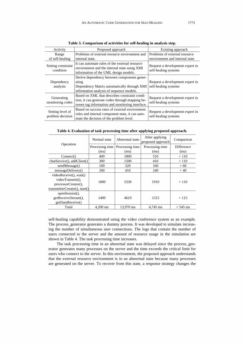
Table 4. Evaluation of task processing time after applying proposed approach.
Normal state Abnormal state After applying proposed approach Comparison
Operation Processing time
(ms) Processing time
(ms) Processing time
(ms) Difference
(ms) Connect() 400 1800 510 + 110
chatService(), addClient() 300 1500 410 + 110 sendMessage() 100 320 160 + 60
messageDelivery() 200 410 240 + 40 videoReceive(), wait()
videoTransmit(), processorCreator(),
transmitterCreater(), start()
1800 5330 1910 + 110
openSession(), getReceiveStream(),
getDataReceive() 1400 4610 1515 + 115
Total 4,200 ms 13,970 ms 4,745 ms + 545 ms
self-healing capability demonstrated using the video conference system as an example. The process_generator generates a dummy process. It was developed to simulate increas-ing the number of simultaneous user connections. The logs that contain the number of users connected to the server and the amount of resource usage in the simulation are shown in Table 4. The task processing time increases.
The task processing time in an abnormal state was delayed since the process_gen- erator generates many processes on the server and the time exceeds the critical limit for users who connect to the server. In this environment, the proposed approach understands that the external resource environment is in an abnormal state because many processes are generated on the server. To recover from this state, a response strategy changes the

JEONGMIN PARK, HYUNSANG YOUN AND EUNSEOK LEE
1774
server configuration. The proposed approach is tested in these scenarios and the task processing time compared to that of an abnormal state (Table 4).
Although the processing time of the proposed approach takes 545ms longer than the task processing time in the normal state, overall the proposed approach has capability to deal with recovery from an abnormal state to a normal state. Our test case used the simi-lar test environment as simulated by RAINBOW Framework [2]. If the proposed ap-proach is applied to a system with a larger scale, the generated self-healing code may impact the performance significantly. However, generally, high levels of reliability can only be achieved at the expense of system performance. Self-healing software, on the other hand, dependable software includes extra, often redundant, code to perform the necessary checking for exceptional system states and to recover from system faults. This reduces system performance and increases the amount of store required by the software. It also adds significantly to the costs of system development. Thus, developers or analysts developing self-healing software must usually make a trade-off between system per-formance and system reliability. Through this experiment, we have known that improv-ing performance of self-healing software is a work of vital importance. Currently, we are pursuing the investigation for this new subject. Our planning future interests include not only improving system reliability but also improving system performance. 5.2 Configuration Environment of E-Commerce System and Actions
The second case study is to develop the intelligent E-commerce system using agents. We apply our methodology to the commercial e-commerce system (Gache)1. We imple-ment agents on the Gache system. Fig. 18 shows architecture of E-commerce system ap-plied as the case study. The E-commerce system is composed of WEB server and DB server as 2-tier. Client area has access to WEB server that provides Browsing service, Recommending service and Purchasing service through internet. If Client wants to pur-chase items, WEB server updates information on users and items in DB server to rec-ommend the items required by client.
Fig. 18. Overall architecture of e-commerce system for the case study.
Based on multi agents, the E-commerce system analyzes user preference, and rec-
ommends appropriate items to client. Hence, it provides client with an intelligent service helping purchase and payment for goods. Table 5 explains the agents operating in E-com- merce system.
1 E-commerce system of SHCorp which was developed by Prof. Eunseok Lee and Software Engineering Lab. members on Sungkyunkwan University, http://jakarta.apache.org/jmeter/usermanual/index.html.

AN AUTOMATIC CODE GENERATION FOR SELF-HEALING
1775
Table 5. The list of agents for the intelligent e-commerce service.
Agent Location Provided services
Commerce agent Web server − Providing item list − Recommending item
User agent Client − Cart service − Purchasing item, retrieving point
Order agent Web server − Charging
• Commerce Agent (CA): CA located in WEB server provides item list and recommends
item that user like based on user profile in database. • User Agent (UA): UA positioned in client, temporarily, safekeeps items into cart or
provides services purchasing item and retrieving point of it. • Order Agent (OA): OA located in WEB server deliveries service regarding payment
for goods.
The class diagram that shows the design of each agent is represented by Fig. 19. The setup() method provides the function which initiates an agent. The action() imple-ments the service of each agent. The agents on the E-commerce system offer the services through the communication with other agents. For example, the user agent interacts with the commerce agent to receive the list of recommended items, and also communicates to the order agent to pay the charge of item.
Fig. 19. Class diagram for the e-commerce system.

JEONGMIN PARK, HYUNSANG YOUN AND EUNSEOK LEE
1776
Browsing itemssd
CombinedFragment1alt
CombinedFragment8alt
ca : CommerceAgentua : UserAgent
1 : request-item()
2 : refused()
3 : agree()
4 : failure()
5 : inform-result:inform()
Fig. 20. Sequence diagram for the recommending and the browsing service.
Fig. 20 shows the scenario which the user agent requests the list of item to the com-
merce agent. The commerce agent that receives the request message (request-item()) can agree or refuse it. The commerce agent retrieves the preference of the user from database and sends the list of recommended items if the agent agrees the request message. The commerce agent sends failure message when there is not the list in the database.
When a fault of the e-commerce system is discovered during run time, the system solves this problem using self-healing mechanism. For example, when the database con-nection problem is occurred at the commerce agent to process the request message, the commerce agent performs self-healing.
Fig. 21 shows the commerce agent to process the request message. Commerce agent has 4-states (Initiated, Waiting, Active, Suspended), and the service of this agent is pro-vided at the Active state only. When the commerce agent receives the request message, the state of this agent enters to the requested state, and then can be transited into the re-fused state or the agreed state. The agent on the agreed state connects to the database to retrieve user data and item list. If the connection is failed, this agent transits the state into the self-healing state. In the self-healing state, the commerce agent analyzes this problem and then connects to the redundant database and then repair the database.
The CG generates the monitoring code for self-healing shown by Fig. 22. The analysis() function gathers the monitoring data for the database connection and manage-ment, and then this system connects to the alternative database before the healing.
To compare the performance of system that is running on the normal state or failure state, we inject the fault with regard to the database connection into the system randomly. We use Apache Jmeter v2.3.12 to measure the performance of the system. Jmeter is a Java desktop application designed to load test functional behavior and measure per-formance. Jmeter can allocate workload to HTTP, FTP servers and SQL query. Jmeter also offers simultaneous connection based on multi-threading. We create three types of
2 The User’s manual of Apache Jmeter, http://jakarta.apache.org/jmeter/usermanual/index.html.

AN AUTOMATIC CODE GENERATION FOR SELF-HEALING
1777
Initiated
entry/register()do/setup()exit/action()
Waiting
do/wait(time)
Suspended
do/suspend()
Active
do/listenrequested
entry/receive()do/check()
refused
do/send(message)
agreed
entry/send(message)do/createlist.acion()
refuse
agree failed
do/send(message)
informed
do/send(message)
there is not item list
item list
there is not item listfailure
InvokeSuspend Resume
Wait
Wake up Quit
receive message
Create
return
self-Healing
analysis
Healed
do/createlist.action()
data recoverying
connecting alternativesconnection failed
data damaged
fix
recovery
not healed
call adminitem list
Fig. 21. State diagram for the commerce agent.
Fig. 22. Generated code for system monitoring and analysis.
thread (browser, purchaser, and recommender) for simultaneous connection. We separate the workload of each of the three threads to 10 workstations. The number of virtual cli-ents is 1000. The performance index measured is system response time.
The system response time on the normal state is 68 (ms) represented by Fig. 23. In this figure, the horizontal axis is the system operation time described by minute. The vertical axis is the system response time, which is represented by millisecond.
The response time of the system shown by Fig. 24 represents the result of self-heal- ing. System fault is injected to this system randomly. The steep slope in this figure ex-plains shows that 20 (ms) or so is spent at the self-healing state.

JEONGMIN PARK, HYUNSANG YOUN AND EUNSEOK LEE
1778
Fig. 23. System response time on the normal state.
Fig. 24. System response time on the fault injected state.
6. CONCLUSION
In this paper, we have proposed a self-healing software architecture supported auto-matic code generation approach using productions of design level. This reduces the anal-ysis effort required by the developer. The conclusion which can be drawn from this pa-per are theses:
• Automatic generation of constraint conditions of external and internal states using de-
sign models can be performed. In a complex software environment much effort is re-quired by developers to analyze for self-healing systems and to generate constraint con-ditions explicitly. It is possible to change constraint conditions since generated models at the design level are linked with the constraint condition automatic generation mecha-nism. This reduces the load on the developer to analyze the requirements for the self- healing system.

AN AUTOMATIC CODE GENERATION FOR SELF-HEALING
1779
• Supporting link analysis: link analysis can extract essential information based on de-sign models. It provides standards to identify components that interact with a specific component, and the detailed interactions of these components.
• Problem decision level automation: it supports problem decision of the specific states based on the constraint conditions of the external environment and the internal state of target system. This makes it easy to diagnose problems of the target system. It is possi-ble to reduce analysis efforts required of developers of problem decision level for self- healing.
• Scalability of design support for self-healing: if artifacts supporting problem decision in software design level are expanded, it is easy to extract the basic information that represents the problem state correctly. Since the semantic structure of proposed soft-ware self-healing is captured it is possible to support an extended design for self-heal-ing.
In order to apply this process to a real application many problems must be solved.
The most difficult problem is to be development effort required by the software design-ers to acquire knowledge for self-healing systems, and developing effective self-healing strategy is required for internal state of target system. Also Implementing RGE requires much effort to extract essential information since a large amount of XMI information is generated by the design models. Theses tentative conclusions await further refinement and corrections in the light of further research. As continuation of the work reported here, we are planning to consider the following problems: • Categorize various self-healing strategies, assign priorities to them and classify sepa-
rate problem decision levels for them. • Find out the minimum faulty resources set if there are multiple failures at the same time. • Based on the information generated in the problem detection stage, design appropriate
problem resolution algorithms. • Analyze overall performance problem caused by self-healing code.
REFERENCES
1. R. K. Ravi and V. Sathyanarayana “Container based framework for self-healing software system,” in Proceedings of the 10th IEEE International Workshop on Fu-ture Trends of Distributed Computing Systems, 2004, pp. 306-310.
2. D. Garlan, S. W. Cheng, A. C. Huang, B. Schmer, and P. Steenkiste, “Rainbow: Ar-chitecture-based self-adaptation with reusable infrastructure,” IEEE Computer, Vol. 37, 2004, pp. 46-54.
3. M. Weiser, “The computer of 21st century,” Scientific American, Vol. 265, 1991, pp. 94-104.
4. J. O. Kephart and D. M. Chess “The vision of autonomic computing,” IEEE Com-puter, Vol. 36, 2003, pp. 41-50.
5. D. S. Wile and A. Egyed, “An externalized infrastructure for self-healing systems,” in Proceedings of the 4th Working IEEE/IFIP Conference on Software Architecture, 2004, pp. 285-288.

JEONGMIN PARK, HYUNSANG YOUN AND EUNSEOK LEE
1780
6. D. Garlan and B. Schmerl, “Model-based adaptation for self-healing systems,” in Proceedings of the 1st Workshop on Self-Healing Systems, 2002, pp. 27-32.
7. M. E. Shin, “Self-healing components in robust software architecture for concurrent and distributed systems,” Science of Computer Programming, Vol. 57, 2005, pp. 27- 44.
8. M. E. Shin and J. H. An, “Self-reconfiguration in self-healing systems,” in Proceed-ings of the 3rd IEEE International Workshop on Engineering of Autonomic and Autonomic Systems, 2006, pp. 89-98.
9. IBM, Autonomic Computing, “IBM’s perspective on the state of information tech-nology,” http://www.ibm.com/industries/government/doc/content/resource/thought/ 278606109.html.
10. J. Park, G. Yoo, C. Jeong, and E. Lee, “Self-management system based on self-heal- ing mechanism,” Lecture Notes in Computer Science, Vol. 4238, 2006, pp. 372-382.
11. I. Sommerville, Software Engineering, 8th ed., Addison-Wesley, Boston, pp. 345- 355, 2007.
12. UML Online Document, http://www.omg.org/xml. 13. XMI Online Document, http://www.omg.org/xml. 14. Q. Wang, “Towards a rule model for software-adaptive software,” ACM SIGSOFT
Software Engineering Notes, Vol. 30, 2005, pp. 1-5. 15. StarUML, http://staruml.sourceforge.net/en/. 16. Eclipse Plug-in Development Environment, http://eclipsewiki.editme.com/PDE. 17. Eclipse Modeling Framework, http://www.eclipse.org/emf. 18. N. Delgado, A. Q. Gates, and S. Roach, “A taxonomy and catalog of runtime soft-
ware-fault monitoring tools,” IEEE Transactions on Software Engineering, Vol. 30, 2004, pp. 859-872.
19. S. Lee, J. H. Lee, and E. Lee, “An inference engine for personalized content adapta-tion in heterogeneous mobile environment,” Lecture Notes in Computer Science, Vol. 4239, 2006, pp. 158-170.
20. J. Schmuller, Sams Teach Yourself UML in 24 Hours, 3rd ed., SAMS Publishing, Indianapolis, 2004, pp. 168-180.
Jeongmin Park (朴正民) received the B.S. degree in Com-puter Engineering from Korea Polytechnic University, Korea, in 2003, M.S. degree in Computer Engineering from Sungkyunk-wan University, Korea, in 2005. He is a full time lecturer of Dongyang Technical College. Also, he is an adjunct professor of the Department of Computer Engineering of Korea Polytechnic University. He is currently a doctoral candidate at Sungkyunk-wan University and a member of the Software Engineering Lab. His research interests include the area of autonomic detection and diagnosis in distributed component-based system.
AN AUTOMATIC CODE GENERATION FOR SELF-HEALING
1781
Hyunsang Youn (尹賢相) received the B.S. degree in In-formation Communication Engineering from Seokyeong Univer-sity, Korea, in 2004, M.S. degree in Computer Engineering from Sungkyunkwan University, Korea, in 2006. He is a member of the Software Engineering Lab. His research interests include the area of model based software performance prediction and analy-sis.
Eunsoek Lee (李殷碩) received his Ph.D. and M.S. degrees in Department of Information Engineering from Tohoku Univer-sity, Japan, in 1992 and 1988, respectively, and his B.S. degree in Electronic Engineering from Sungkyunkwan University, Korea, in 1985. He is a Professor of the Department of Computer Engi-neering of Sungkyunkwan University, Korea. From 1994 to 1995, he was an assistance professor of the Department of Information Engineering of Tohoku University, Japan. He was a research scientist in Information and Electronics Laboratory of Mitsubishi Electric Corporation, Japan, from 1992 to 1994. His areas of re- search include software engineering, autonomic/ubiquitous com-puting and agent-oriented intelligence system.