an authentication for ensuring genuineness of printed ... · based on digital watermarking and...
TRANSCRIPT

An Authentication for Ensuring Genuineness of Printed Document
based on Digital Watermarking and Image Encryption
MISNI HARJO SUWITO†1 YOSHIFUMI UESHIGE†2
KOUICHI SAKURAI†3
Abstract: Information technology is an open medium easily accessible to anyone without exception including miscreants
intending to commit criminal activities. Criminal activities such as printed documents falsifying concern trust of corresponding
issuers. Various methods proposed for securing and authentication of printed document for truth to be achieved. In contrast, if such acts of forgery can succeed with ease issuers of original document lose confidence. For example, at the higher education
institution or university, producing fake degree certificates have become a critical problem. Therefore, institutions need to come
up with innovations to prevent for miscreants to forge such an essential document. Cryptography has applied in diverse application
one of them mainly concentrate on image encryption field. To overcome these problems, a comprehensive approach is needed.
This paper proposes authentication for ensuring genuineness of a printed document based on watermarking and image encryption.
First, executing process discrete wavelet transform-singular value decomposition embedding between host image and watermark image. Second, image encryption and decryption using fractal key and chaos function. The proposed method consists of three
phase such as embedding watermarking, generation key, encryption-decryption fractal, and chaos. The beginning generated a key
to use to encrypt and decrypt image. Then, image encryption fractal by implementing L-shaped trominos for encryption and decryption of embedded images from watermarking. Finally, chaos algorithm is used to encrypt and decrypt images from fractal
decryption, and results should be same as original. Experimental results show that proposed technique is more secure, efficient
with lower computational complexity.
Keywords: Digital Watermarking, Image Encryption, and Decryption, Fractal key, Chaos Function
1. Introduction
The most recent developments of information technology past
two decades are invasion of digital media that has penetrated in
every aspect of daily life. Digital data can be stored very
efficiently with very high quality and can be manipulated easily
using computer. A part from that, it is straightforward to spread
quickly and cheaply through the data communication network
without loss of quality at all. In contrast, for the criminals or
hackers, this is an opportunity to intend to attack the network and
conduct criminal activities. The act of falsifying printed
documents (essential documents) is a critical problem and affects
the loss of confidence of the corresponding issuers. A digital
watermark is one form of steganography technique that can use
for owner identification; ownership proves, broadcast monitoring,
transaction tracking, content authentication, copy control, and
device control. Therefore, effective and efficient watermarking
methods to protect digital data need to develop. Moreover,
information should be share to obtain optimal benefits and
utilization. Thus, security, and information authenticity should be
taken seriously into main objectives of this research.
Encryption is most efficient way to achieve data security. This
process achieves a useful role in hiding message content since
original information can only recover through description process.
Image encryption required for future multimedia security. A
password code for identifying individual users is likely to be
replaced by future fingerprint biometrics and retina scans. It is
also one of the most effective ways to achieve data security. By
applying encryption process, the message of information is
encoded by authorized person. Image Encryption1 (IE) schemes
have been increasingly studied to meet demand for real-time
†1 Kyushu University †2 Nagasaki University
secure image transmission over private or public networks [1-2].
Image Encryption is required for secure and fast image
transmission. Researchers in recent years have presented new
chaotic schemes [3-7].
The characteristic chaos of Fractal's image, appropriate for
designing secure and reliable cryptosystems. The fractal-based
cryptosystem is designed using a complex number rather than the
prime number. Thus, a private key generation and public key is
carried out using complex number arithmetically. The chaotic
nature of fractal leads to key value sensitiveness towards initial
value, makes it difficult to produce an accurate key by intruder.
An additional advantage of using fractal as a key is size, which
impacts on conjecture number that an attacker would need to
make to find key, e.g., brute force attack, i.e., it determines the
feasibility of a collision attack. In case of using fractal keys,
which extend key space, shrink key size and make it more
complex [11].
In this paper, Discrete Wavelet Transform and Singular Value
Decomposition is a technique for embedding and extracting
watermarked imagery. The sub-band coefficient LL3 singular
values of host image are modified with a single binary watermark
image value for authentication and ensuring genuineness of the
printed document. As well Image encryption technique to ensure
authenticity of printed documents is proposed to provide efficient,
high secure transmission with complexity, and low computation
is the main purpose. In the beginning, a generator key is generated
to encrypt and decrypt data and images. Furthermore, image
encryption algorithm processed by applying an L-shaped fractal
encryption. Also, chaos algorithm is also used to encrypt and
decrypt last image, and produce same image. In each encrypted
image, it is decrypted using fractal key and chaos algorithms,
†3Kyushu University

which were preceded by embedding and extracting using
watermarking technique.
In this paper is organized as follows; in Section 2, Tool and
Method, Section 3 Proposed Method, and Section 4 Experiment
Result, and the conclusion in Section 5.
2. Tool and Method
2.1 Discrete Wavelet Transform – Singular Value
Decomposition
Discrete Wavelet Transform (DWT) is a transformation
discrete signal into wavelet coefficients obtained by filtering
signal with two different filters that filter low and high pass filter.
As the name suggests, DWT-SVD refers to combination of both
Discrete Wavelet Transform and Singular Value Decomposition
used in digital watermarking scheme. Discrete Wavelet
Transform (DWT) split (decompose) digital images into four
sections at a frequency sub-band that image. Components sub-
band wavelet transformation generated by lowering the level of
decomposition. Discrete Wavelet Transform (DWT) can be done
by passing a signal via a Low Pass Filter (LPF) and do down-
sampling the output of each filter [12]. Discrete Wavelet
Transform [12] first level of decomposition, there are four sub-
bands: LL1, LH1, HL1, and HH1. In two-dimensional application,
for each level of decomposition, the first show DWT in the
vertical direction, and followed the horizontal direction DWT.
After the first level of decomposition, there are four sub-bands:
LL1, LH1, HL1, and HH1. For each of progressive
decomposition, the LL sub-ban use as the final stage of data. To
perform the second stage of decomposition, discrete wavelet
transform connected to an LL1 band that breaks down into four
sub-bands: LL2, LH2, HL2, and HH2. Furthermore, to
decomposition into the three levels, discrete wavelet transform
has connected LL2 band that breaks the band into four sub-bands:
LL3, LH3, HL3, and HH3. The result in 10 sub-bands per
segment. LH1, HL1, and HH1 containing the highest frequency
band shown in while the frequency band LL3 otherwise. Because
the characteristics of multi-resolution decomposition of the
wavelet transform, wavelet analysis of the image have an
excellent directional selectivity and can combine with the human
visual system.
In DWT-SVD image watermarking, watermark image will be
embedded into host image and remain hidden. There will be two
algorithms used: embedding algorithm and extraction algorithm.
Here are algorithms for embedding and extraction.
2.1.1 Embedding Algorithm
Step-1: Host image input and grayscale watermark image and
change to a two-dimensional matrix.
Step-2: Decompose the host image matrix using DWT into four
matrices, LL, HL, LH, and HH respectively. The DWT
level depends on the size ratio between the host image
and the watermark image (for example, the 1: 2n size
ratio where n is the level DWT).
Step-3: Do SVD on high-level DWT matrix (host image):
Ui∑iViT. To get four singular matrics, ∑i Where i equal
to each LL, HL, LH, and HH.
Step-4: Conduct SVD directly on the watermark image:
Uw∑wVwT to get the singular matrix ∑w
Step-5: Obtain a modified singular value matrix, ∑i* from ∑i..
∑w* is a function of ∑i and ∑w Where the combination
depends on the embedding technique used. Different
insertion techniques will have different ways to obtain a
modified single value matrix.
Step-6: After getting ∑i* do SVD inverse on Ui∑i*ViT (with Ui
and ViT precisely from SVD of high-level DWT matrix-
matrix) to get each modification LL*, HL*, LH*, and
HH*.
Step-7: Do Invers the DWT on these modified LL*, HL*, LH*,
and HH* bands to get a watermarked host image.
2.1.2 Extracting Algorithm
Step-1: Do DWT decomposition on the watermarked host image
to get four frequencies: LL, HL, LH, and HH bands. The
decomposition rate is the same as the decomposition rate
used in the embedding algorithm.
Step-2: Do SVD at the highest DWT frequency: Ui∑i*ViT to
obtain singular matrix ∑i *.
Step-3: Extract the singular matrix of the watermark image, ∑w(i)
of ∑i * according to the extraction function. This process
depends on the embedding function in which the
extraction function is the inverse of the embedding
function.
Step-4: Do an inverse SVD using an extracted singular image
matrix, ∑w(i) (along with the original image watermark
vector Ui and ViT to recover the watermark image.
2.1.3 Performance of Watermarking Algorithm
The following is a measuring tool to test the performance of a
proposed watermarking algorithm.
There are three phase for first level security; first phase to
measure host image quality (similarity level) before and after
insertion watermark; second phase to measure similarity of
original logo with image logo after extraction; third phase to
measure robustness and imperceptibility by giving some attacks
as cropping, noising, blurring, resizing, etc.
Mean Square Error (MSE) is used to calculate image before and
after watermark insertion, which can be expressed by an equation
as follows:
𝑀𝑆𝐸 =1
𝑀𝑁∑ ∑ (𝑆𝑥𝑦 − 𝑁
𝑦=1𝑀𝑥=1 𝑙𝑥𝑦)2 (1)
where x and y are the image coordinates, M and N are image
dimensions S, are the watermark and lxy of the host image.
Peak Signal Noise to Ration (PSNR) which is used to measure
image quality on a logarithmic scale in decibels (dB) if the value
is below 30dB bad image cultivation and when higher than 40dB
is high image quality. The equation can be expressed as follows:
𝑃𝑆𝑁𝑅 = 10𝑙𝑜𝑔10 (𝑙𝑚𝑎𝑥
2
𝑀𝑆𝐸) (2)
Normalized Correlation (NC) is one of measuring tools used to
test watermarked image robustness. The Equation can be
expressed as follows:
𝑁𝐶(𝑊, 𝑊′) =∑ ∑ [𝑊(𝑖,𝑗).𝑊′(𝑖,𝑗)]𝑛
𝑗=1𝑚𝑖=1
∑ ∑ (𝑊(𝑖,𝑗))2𝑛𝑗=1
𝑚𝑖=1
(3)
2.2. Fractal Key
The ability to extend fractal set parameters, and to transform
them uniquely [17]. It proves that there are some different fractals.
Thus the fractal encryption/decryption procedure can be used as
key efficiently.
2.2.1 Fractal Algorithm
In this section, described algorithm used in this study. This
algorithm uses a symmetric key. It’s based on the modulo
operation [18]. This modulo operation has right inverse.
Therefore, this encryption/decryption process algorithm is one-
to-one which means image decryption does not cause damage in
any way. The encryption process is done in two stages. This
algorithm works pixel by pixel. Each pixel consists of R, G, B ϵ
[1, 256] (red, green, and blue) color. It is applied to all of each
layer. For this purposes we define R', G', and B' into matrices
representing one layer of the image to be encrypted, each having
dimension m x n. Next, let RKey, GKey, and BKey be matrices
representing a single key layer, also representing dimensions of
m x n. Then to be able to find R', G', and B', matrix representing
encrypted image layer (dimension m x n), following algorithm is
realized to obtain secret matrix key D’ from fractal:
As an image, R'Key, G'Key, and B'Key are matrices representing a
single key layer, each having dimension m x n.
Image:
(4)
Where
and r(i,j,k,l)= √[𝑲 − 𝒊]𝟐 + [𝑳 − 𝒃]𝟐 as weight. Here, [x] denotes
the floor ꓯx ε R and ẟ is the distance in the pixel of the constructed
grid.
2.2.2 Fractal Encryption
Let R', G,' and B' are a matrix representing a layer of images
to be encrypted, each having m x n dimensions. Matrix E
represents following algorithm for obtaining encrypted images R
', G', and B' (m x n dimension).
ꓯE’ ϵ R, G, B ꓱE’mxn : ꓯi ϵ [1, m], j ϵ [1, n], e’ij = (e’ij + d’ij) mod
256 (5)
Here, mod denotes modular operation. Fig.3 illustrates the
encryption process.
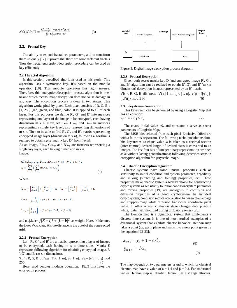
Figure 3. Digital image decryption process diagram.
2.2.3 Fractal Decryption
Given both secret matrix key D 'and encrypted image R', G ',
and B', algorithm can be realized to obtain R', G', and B' (m x n
dimension) decryption images represented by an E' matrix:
ꓯE’ ϵ R, G, B ꓱE’mxn : ꓯi ϵ [1, m], j ϵ [1, n], e’ij = ([e’ij]-
[ d’ij]) mod 256 (6)
2.3 Keystream Generation
This keystream can be generated by using a Logistic Map that
has an equation:
xi+1 = r xi (1- xi) (7)
The chaos initial value x0, and constants r serve as secret
parameters of Logistic Map.
The MSB bits selected from each pixel Exclusive-ORed are
with a four-bits keystream. The following technique obtains four-
bits keystream ki: chaos value xi is taken as a decimal section
(after comma) desired length of desired sizes is converted to an
integer. The last four bits of integer binary representation are ones
as ki without losing generalizations; following describes steps in
encryption algorithm for grayscale image.
2.4 Chaotic Encryption algorithm
Chaotic systems have some unusual properties such as
sensitivity to initial condition and system parameter, ergodicity
and mixing (stretching and folding) properties, ect. These
properties make chaotic system a worthy choice for constructing
cryptosystems as sensitivity to initial condition/system parameter
and mixing properties [19] are analogous to confusion and
diffusion properties of a good cryptosystem. In an ideal
cryptosystem, confusion reduces correlation between plain-image
and chipper-image while diffusion transposes coordinate pixel
value. In other words, confusion stage changes data position
while, data itself modified during diffusion process [20].
The Hennon map is a dynamical system that implements a
discrete-time system. It is one of most studied examples of a
dynamical system that exhibits chaotic behavior. Hennon map
takes a point (xn, yn) in plane and maps it to a new point given by
the equation [22-23]:
(8)
(9)
The map depends on two parameters, a and β, which for classical
Hennon map have a value of a = 1.4 and β = 0.3. For traditional
values Hennon map is Chaotic. Hennon has a strange attractor.
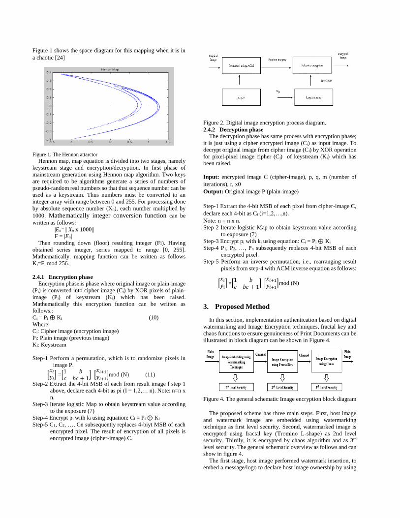
Figure 1 shows the space diagram for this mapping when it is in
a chaotic [24]
Figure 1. The Hennon attarctor
Hennon map, map equation is divided into two stages, namely
keystream stage and encryption/decryption. In first phase of
mainstream generation using Hennon map algorithm. Two keys
are required to be algorithms generate a series of numbers of
pseudo-random real numbers so that that sequence number can be
used as a keystream. Thus numbers must be converted to an
integer array with range between 0 and 255. For processing done
by absolute sequence number (Xn), each number multiplied by
1000. Mathematically integer conversion function can be
written as follows:
|En=|| Xn x 1000||
F = |En|
Then rounding down (floor) resulting integer (Fi). Having
obtained series integer, series mapped to range [0, 255].
Mathematically, mapping function can be written as follows
Ki=Fi mod 256.
2.4.1 Encryption phase
Encryption phase is phase where original image or plain-image
(Pi) is converted into cipher image (Ci) by XOR pixels of plain-
image (Pi) of keystream (Ki) which has been raised.
Mathematically this encryption function can be written as
follows.:
Ci = Pi ⊕ Ki (10)
Where:
Ci: Cipher image (encryption image)
Pi: Plain image (previous image)
Ki: Keystream
Step-1 Perform a permutation, which is to randomize pixels in
image P.
[𝑥𝑖
𝑦𝑖] =[
1 𝑏𝑐 𝑏𝑐 + 1
] [𝑥𝑖+1
𝑦𝑖+1]mod (N) (11)
Step-2 Extract the 4-bit MSB of each from result image f step 1
above, declare each 4-bit as pi (I = 1,2,… n). Note: n=n x
n.
Step-3 Iterate logistic Map to obtain keystream value according
to the exposure (7)
Step-4 Encrypt pi with ki using equation: Ci = Pi ⊕ Ki
Step-5 C1, C2, …, Cn subsequently replaces 4-biyt MSB of each
encrypted pixel. The result of encryption of all pixels is
encrypted image (cipher-image) C.
Figure 2. Digital image encryption process diagram.
2.4.2 Decryption phase
The decryption phase has same process with encryption phase;
it is just using a cipher encrypted image (Ci) as input image. To
decrypt original image from cipher image (Ci) by XOR operation
for pixel-pixel image cipher (Ci) of keystream (Ki) which has
been raised.
Input: encrypted image C (cipher-image), p, q, m (number of
iterations), r, x0
Output: Original image P (plain-image)
Step-1 Extract the 4-bit MSB of each pixel from cipher-image C,
declare each 4-bit as Ci (i=1,2,…,n).
Note: n = n x n.
Step-2 Iterate logistic Map to obtain keystream value according
to exposure (7)
Step-3 Encrypt pi with ki using equation: Ci = Pi ⊕ Ki
Step-4 P1, P2, …, Pn subsequently replaces 4-bit MSB of each
encrypted pixel.
Step-5 Perform an inverse permutation, i.e., rearranging result
pixels from step-4 with ACM inverse equation as follows:
[𝑥𝑖
𝑦𝑖] =[
1 𝑏𝑐 𝑏𝑐 + 1
] [𝑥𝑖+1
𝑦𝑖+1]mod (N)
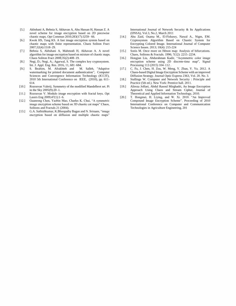
3. Proposed Method
In this section, implementation authentication based on digital
watermarking and Image Encryption techniques, fractal key and
chaos functions to ensure genuineness of Print Documents can be
illustrated in block diagram can be shown in Figure 4.
Figure 4. The general schematic Image encryption block diagram
The proposed scheme has three main steps. First, host image
and watermark image are embedded using watermarking
technique as first level security. Second, watermarked image is
encrypted using fractal key (Tromino L-shape) as 2nd level
security. Thirdly, it is encrypted by chaos algorithm and as 3rd
level security. The general schematic overview as follows and can
show in figure 4.
The first stage, host image performed watermark insertion, to
embed a message/logo to declare host image ownership by using

watermarking technique. After perform embedding and
extracting the results are same as original without any changes,
both host image and watermark/logo. It is very difficult to
distinguish between the host image before inserted and the host
image that has been inserted by human vision. It shows that this
technique is quite robust against attacks such as cropping, noising,
blurring, etc. The embedding process result can be shown figure
5.
Figure 5. Embedding Citra host using watermarking technique.
The second stage, After, finishing first process, then proceed to
second process by encrypting host image of with different scheme
(using Fractal Key). The host image will be encrypted using
fractal key with L-shape Tromino. This second scheme has high
sensitivity characteristics. Here, identified keys used as keys in
encryption and decryption rules or procedures. Attributes such as
coordinates, iterations, and zooms are required to generate fractal
image. If there is a slight change in value, then host image will
change in a dramatically. This means that failing cannot restore
original host image /original image. When host image encryption
is completely unrecognizable, host image looks very messy and
cluttered. Then do description, then host image back as before,
without any difference. So in this second stage it can also be
called a 2nd - security level. Figure 6 is shown image encryption
result using Fractal Key.
Figure 6. Image Encryption using Fractal Key process
The third stage, Host Image is done encryption with different
scheme. This scheme is also known as chaotic scheme, when
subject is encrypted, the result is really different from second
scheme. The purpose of this encryption is to randomize host
image. Chaos is known for its high sensitivity and is very
vulnerable to changes in initial value. Sensitive means that if this
key changed slightly, decryption of cipher-image would produce
different ciphers in a different meaning from original image (host
image). Then do description and results are same. Then it can be
called 3rd security level. Figure 7 is a visual result of chaos
encryption technique as 3rd level security.
Figure 7. The result of Chaos Image Encryption
4. Experiment Result
The image selected for this experiment are ‘’Village’’, ‘’
Marlena’’, ‘’Peppers’’, and ‘’Sailboat’’, which greyscale and
image of size 512 x 512 using format *.JPG and as a watermark
(logo) is a with size 512 x 512 and format JPG can show in table
1. The proposed algorithm implemented using MATLABR2016a
programming language on laptops, with Windows OS 10, 64-bit
CPU Core i7, 4GB RAM installed.
Table 1. Image Data Testing
In experimental stage, embedding and extraction process done by
using watermarking technique, while for encryption and
decryption process using fractal key and chaos map by applying
some image. The image data used in experiment in this research
can show in table 1. As for experimental process done with three
stages that have described in chapter 3. Then to know the
results of this experiment can show in table 2.
Table 2. Data Image Testing and Result.

5. Security Analysis In this section will discuss evaluasion of above algorithm.
Evaluasion security analysis includes key space analysis,
sensitivity analysis, entropy analysis, histogram analysis, and
correlation analysis.
5.1 Key Space Analysis Space key to declare a different total number that can be used
to perform encryption/decryption [25]. Brute-force attacks try all
possible keys to decrypt. For brute-force attacks to be ineffective,
key space must be larger. Also, secret key parameters used in this
encryption algorithm are more than one, p, q, m, x0, and r. In
Matlab it can support a maximum unsigned integer of up to 32
bits, so possible optional value is 232 = 4.3 x 10⁹. For initial value
of Logistic Map (x0), computational precision for 64-bit double-
precision according to IEEE floating-point standard is 10-15 [25],
so number of possible values of x0 is 1015. Thus, key space is
entirely:
H(p,q,m,x0,r)(4.3 x 109)x(4.3 x 109)x(4.3 x 1015)x(4.3 x 1015)
18.49 x 1048
With large key space size so that algorithms can withstand
brute-force attacks. Time required to try all combinations of keys
(exhaustive search [26] can show table 3
Table 3. Time Required to Try Exhaustive Key Search
In Table 3 it is shown that time taken to try whole key
combination is about 3,215 x1016 using a super fast computer that
can perform 1 million test per second. We can imagine that to find
out just takes a long time to complete two key combinations that
can lead to inefficient brute-force attacks.
5.2 Key Sensitivity Parameter Analysis
Chaos has a sensitive nature, and it is one of Chaos
characteristics against small changes in initial value. When
applied to image encryption means that if key experiences a slight
change, decryption process generates a significantly different
image of other cipher (failing to return the cipher-image to
original plain-image).
Take a look, algorithm proposed in this paper in section II;
Logistic Map is used to generate chaos value, extract four bits of
value, and then XORed with 4-bit pixels. A small change initial
value (x0) renders random values generated from Logistic Map
significantly different after Logistic Map process repeatedly. The
effect of small changes resulted, keystream also differed
significantly, and Exclusive-OR operation gave significantly
different image results.
Suppose x0 converted to x0 + Δ then a cipher-image is
decrypted with key. For example, Δ = 10-10 so initial value of
Logistic Map is 0.4500000001. The image decryption 'Sailboat'
cipher can be shown in figure 8. This experiment shows that the
chaos characteristics sensitivity provide good security from
widespread attacks. The slightest change to secret key will result
in decryption process resulting in a wrong (different) image.
(a) Cipher-image of Village image Histogram from (a)
( c) Village-image after decryption Histogram from (c)
(with small change to x0 of Δ = 10-10)
Figure 8. Result of decryption experiment with small change to x0 of Δ =
10-10
5.3 Entropy Analysis
Referring to Information Theory, entropy to express the degree of
uncertainty in the system. The m message entropy is calculated
by equation [6]:
(9)
Where, in this case, P (mi) to express the mi probability symbol
in message and entropy expressed for bit unit. The random
message should have ideal entropy equal to 8, whereas in less
random message entropy value is less than eight. If entropy value
is less than eight, then there is a predictability degree which is a
security threat [27].
In this case image encryption, resulting cipher-image should be
ideally 8. In grayscale image there are 256 gray values (m0 = 0,
m1 = 1, ..., m255 = 255) and possibly of each gray value is
calculated from its histogram. Without generalization loss, we
calculate entropy for grayscale image only. For cipher-image in
Figure 2 (a) the entropy is
The entropy result value (7,9991) is very close to 8; this means
secure encryption algorithm of entropy attack to predict from
information in image.
5.4 Histogram Analysis
Using a histogram, an attacker can perform a frequency
analysis to infer a secret key or plain pixel. This kind of attack is
called a statistical attack. The cipher-image histogram should be
made differently to prevent from statistical attacks, so as not to
have statistical similarities. Therefore, the cipher-image
histogram must be relatively flat or statistically uniform
distribution. A relatively uniform cipher image distribution is an
indication that the image encryption algorithm is of good quality
[27].
Figure 9 (a) shows the 'Village..' image histogram before it is
encrypted, and image (b) is the cipher-image histogram after
encrypted. The cipher-image histogram looks flat and is
significantly different from plain-mage histogram.

(a) Before encryption (b) After encryption
Figure 9. Histogram plain-image ‘village’ and Histogram cipher-
image ‘village.’ It is the same as 'village' histogram of each color
looks flat. Based on the experimental results above, a flat
histogram on cipher-image can make attacker difficult to infer
pixel value or secret key by using a statistical attack.
5.5 Correlation Analysis
Correlation is a measure that states the relationship strength
between linear between random variables. Let x and y be two
random variables, two discrete random correlation variables each
of n elements expressed by correlation coefficient calculated by
following equation [28]:
(10)
which in this case is
(covariation) (11)
(standard deviation) (12)
(average) (13)
The correlation coefficient value cannot exceed 1 in absolute
value. The correlation coefficient +1 value denotes perfect linear
correlation, the correlation coefficient -1 denotes perfect linear
correlation, while between -1 and +1 express linear dependence
degree between two random variables. Coefficient values close to
-1 or +1 represent a weak linear relationship.
In most plain-image imagery, correlation coefficients between
pixels in series are usually high (close to +1 or -1). The image
encryption purpose is to remove correlation between pixels or to
make correlation coefficient close to 0.
To investigate plain-image correlation and cipher-image, we
calculate correlation coefficient between two horizontally
neighboring pixels [f (i, j) and f (i, j) +1)], two vertically
neighboring p [ (i, j) and f (i + 1, j)] and two diagonally
neighboring pixels [f (i, j) and f (i + 1, j + 1)], both in plain-image
and on cipher -image.
In this experiment, a randomly selected 1000 pixel pairs are
located in each direction (vertical, horizontal, and diagonal) from
the 'village' image along with the experimental image results. The
correlation coefficient is calculated by (6), in which case x and y
are two neighboring pixels gray. Experimental results can show
in Table 4.
Table 4. A table comparison of correlation coefficients
between two neighboring pixels.
Table 4 it can be seen that correlation coefficient on
neighboring pixels in each direction in plain-image value is at 1,
which indicates a strong correlation between pixels, but in cipher-
image correlation coefficient is near zero, indicating pixel
neighboring pixels are no longer correlated. Figure 5 shows
neighboring pixel distribution correlations on each plain-image
(left column) and cipher-image (right column). In plain-images,
their values neighboring pixels are around the 45o (degree),
diagonal line, indicating a strong correlation between pixels. In
contrast, in cipher-image, pixel values are evenly distributed
across plane area, which indicates that pixels inside are no longer
correlated.
Figure 10. Distribution of correlation of neighboring pixels in the
plain-image and the cipher-image of ‘village.’
6. Conclusion
In this paper, presented a watermarking algorithm for
embedding digital imagery and combining with fractal key and
chaotic function to encrypt watermark to ensure authenticity and
watermark image security. The chaotic nature of fractal functions
and large-size encryption key algorithms, sensitivity to small
changes in initial values creates an immune attack from
exhaustive-key search attack.
From experimental results show that this algorithm can
conclude that:
a. The Encryption requirement is to encrypt and decrypt image
the result should be same as original.
b. The composition and image color diversity have no
significant effect on encryption and decryption time process.
In images that have high color composition and diversity
with images that have a low color, the composition has same
encryption and decryption time process.
c. The encryption algorithm has a key space for 1030 and a
sensitivity of 10-16, so this algorithm is complicated to crack
by brute force attacks.
Thus, digital image encryption algorithm is complicated to
solve by brute force attack and have high-security quality.
Reference: [1.] B. Murugan and A.G.N. Gounder, “Image encryption scheme
based on block-based confusion and multiple levels of diffusion”, IET Computer Vision, Vol.10, No.6, pp.593-602, 2016.
[2.] F. Sun, S. Liu, Z. Li, and Z. Lü, “A novel image encryption
[3.] Kwok HS, Tang KS. A fast image encryption system based on chaotic maps with finite representation. Chaos Soliton Fract
2007;32(4):1518–29.
[4.] Pareek NK, Patidar V, Sun KK. Image encryption using chaotic logistic map. Image Vision Comput 2006;24(9):926–34.
[5.] Akhshani A, Behnia S, Akhavan A, Abu Hassan H, Hassan Z. A
novel scheme for image encryption based on 2D piecewise chaotic maps. Opt Commun 2010;283(17):3259– 66.
[6.] Kwok HS, Tang KS. A fast image encryption system based on
chaotic maps with finite representation. Chaos Soliton Fract 2007;32(4):1518–29.
[7.] Behnia S, Akhshani A, Mahmodi H, Akhavan A. A novel
algorithm for image encryption based on mixture of chaotic maps. Chaos Soliton Fract 2008;35(2):408–19.
[8.] Negi, D.; Negi, A.; Agarwal, S. The complex key cryptosystem.
Int. J. Appl. Eng. Res. 2016, 11, 681–684. [9.] S. Ibrahim, M. Afrakhteh and M. Salleh, "Adaptive
watermarking for printed document authentication”, Computer
Sciences and Convergence Information Technology (ICCIT), 2010 5th International Conference on IEEE, (2010), pp. 611-
614.
[10.] Rozouvan Valerij. Symmetry of the modified Mandelbrot set. Pi in the Sky 2005(9):20–1.
[11.] Rozouvan V. Modulo image encryption with fractal keys. Opt
Lasers Eng 2009;47(1):1–6. [12.] Guanrong Chen, Yaobin Mao, Charles K. Chui, “A symmetric
image encryption scheme based on 3D chaotic cat maps” Chaos,
Solitons and Fractals 21 (2004). [13.] G.A. Sathishkumar, K.Bhoopathy Bagan and N. Sriraam, “image
encryption based on diffusion and multiple chaotic maps”
International Journal of Network Security & Its Applications
(IJNSA), Vol.3, No.2, March 2011 [14.] Abu Zaid, Osama M., El-Fishawy, Nawal A., Nigm, EM.
Cryptosystem Algorithm Based on Chaotic System for
Encrypting Colored Image. International Journal of Computer Science Issues. 2013; 10(4): 215-224
[15.] Sonis M. Once more on Hénon map: Analysis of bifurcations.
Chaos, Solitons & Fractals. 1996; 7(12): 2215–2234. [16.] Hongjun Liu, Abdurahman Kadir, “Asymmetric color image
encryption scheme using 2D discrete-time map”, Signal
Processing 113 (2015) 104–112 . [17.] C. Fu, J. Chen, H. Zou, W. Meng, Y. Zhan, Y. Yu. 2012. A
Chaos-based Digital Image Encryption Scheme with an improved
Diffusion Strategy. Journal Optic Express 2363, Vol. 20. No. 3. [18.] Stallings W. Computer and Network Security : Principle and
Practice (5th ed.). New York: Prentice hall. 2011.
[19.] Alireza Jolfaei, Abdul Rasoul Mirghadri, An Image Encryption Approach Using Chaos and Stream Cipher, Journal of
Theoretical and Applied Information Technology, 2010.
[20.] T. Hongmei, H. Liying, and W. Xi. 2010. “An Improved Compound Image Encryption Scheme”. Proceeding of 2010
International Conference on Computer and Communication
Technologies in Agriculture Engineering, 201