an architecture for fast and accurate control of shape
TRANSCRIPT

An Architecture for Fast and Accurate Control of Shape Memory
Alloy Actuators
Yee Harn TehDept. Information EngineeringAustralian National UniversityCanberra ACT 0200, Australia
Roy FeatherstoneDept. Information EngineeringAustralian National UniversityCanberra ACT 0200, Australia
Abstract
This paper presents a new control architecture for fast, accurate force control of antagonistic pairsof shape memory alloy wires. The main components are: a differential-mode controller, which controlsthe output force, an anti-slack mechanism, a rapid-heating mechanism and an anti-overload mechanism.The closed-loop response is fast and accurate, even in the presence of large external motion disturbances.There is no sign of limit cycles; and the performance is unaffected by large load inertias. This paper alsopresents an architecture for position control, in which a position feedback loop is added to the force controlarchitecture. Experimental results show force control accuracies as high as 1mN in a ±3N range, forceoutput rates as high as 50Ns−1, and highly accurate position control with steady-state errors below theresolution of the position encoder.
1 Introduction
Wires made of Shape Memory Alloy (SMA) can be stretched easily when cool, but will contract forcefullyback to their original length when heated. This effect can be harnessed to make actuators for robots and othermechanical devices. SMA actuators are well adapted for flexible and miniaturised force control applicationsdue to their high force-to-weight ratio, mechanical simplicity, compactness, as well as silent, clean operation.Force control applications are very important for robotics, and they include robotic grippers and medicaldevices, as well as force contact applications. However, SMA actuators have disadvantages, including energyinefficiency, slow speed and inaccurate response. Most SMA robotic applications remain in the research andexperimental phase.
In this paper, we present our research on SMA force and position control architectures, using an actuatorbased on an antagonistic pair of SMA wires. The force control architecture consists of a differential controller,an anti-slack mechanism, a rapid-heating mechanism, and an anti-overload mechanism. Our results showfast and very accurate responses to force commands with no sign of limit cycles. In particular, the rapid-heating mechanism allows the safe delivery of very large heating powers without the risk of overheating, bycalculating a safe upper limit to the instantaneous heating power from measurements of electrical resistance.This allows the control system to achieve a maximum force rate of 50Ns−1. This speed is achieved withoutcompromising the setpoint accuracy, with error amplitudes at steady-state of only 0.001N. The possibility ofactuator damage due to overheating and overstressing has been minimised using effective control algorithmssuch as the rapid-heating and anti-overload mechanisms. The force control architecture forms the inner loopin the proposed two-loop position control system. This control system achieves highly accurate responses withno limit cycles in the presence of large load inertias. The research described in this paper can be utilised forpractical SMA actuator and robotic applications.
An outline of the paper is first provided. Section 2 contains some background information about SMA aswell as a review of past research aimed at improving the performance of SMA actuators. In Section 3, theexperimental test bed used for all of the experimental work is described. Section 4 describes the completearchitecture of the differential force control system as well as the experimental results. In Section 5, experi-mental results are presented to demonstrate good rejection of external motion disturbances and load inertias.Finally, in Section 6, we propose a new two-loop position control architecture with a fast inner force loop
0The final, definitive version of this paper has been published in the International Journal of Robotics Research, vol. 27,no. 5, May 2008 by Sage Publications Ltd. All rights reserved. c© SAGE Publications Ltd. 2008. It is available athttp://online.sagepub.com/
1

based on the differential force controller and a slower outer position loop. Experimental results with the SMAactuator under heavy external loads are presented.
2 Background
Shape Memory Alloy exhibits a shape memory effect, which is the result of a phase transformation betweena martensite crystal structure, which predominates at low temperatures, and an austenite crystal structure,which predominates at higher temperatures. The martensite phase has a low yield strength, and is easilydeformed. However, the original shape of the material is recovered when it is heated, as the deformed marten-site transforms into undeformed austenite. The phase transformation is nonlinear, and exhibits large thermalhysteresis.
The shape memory effect is the basis of actuator applications for SMA. There are two main types of theshape memory effect:
1. One-way shape memory effect — At the martensite phase, the alloy can be easily stretched using anexternal force. After removal of the force, the alloy shows permanent deformation. It can recover itsoriginal shape upon heating. Subsequent cooling does not change the shape unless it is stressed again.
2. Two-way shape memory effect — In addition to the one-way effect, shape change occurs upon coolingand without the applying of external stress. The SMA usually needs to be trained to exhibit the two-wayeffect.
Heating the SMA actuators can be done via Joule heating, which is resistively heating the actuators usingelectric current. SMA actuators can be used in various configurations including helical springs, cantileverstrips, straight wires, torsion tubes and torsion springs (Waram, 1993). Because SMA actuators can onlycontract in one direction, it is necessary to provide a biasing force to return them to the neutral position. Thiscan be accomplished using a dead weight, a bias spring, or another SMA element in a differential arrangement.In practice, the latter two arrangements are usually used. SMA actuator applications include linear actuators,micro-switches, micro-valves, robotic grippers, vibration control and active damping of structures, medicalendoscopes and micro-electro-mechanical systems (MEMS) (Fu et al., 2004; Ikuta et al., 1988; Kohl, 2004;Liang and Rogers, 1993; Van Humbeeck, 1999).
Pioneering research on SMA actuators and material treatment included Bergamasco et al. (1990) andHunter et al. (1991) in the early 1990s. More recent works on SMA control included Dickinson and Wen(1998), Elahinia and Ashrafiuon (2002), Madill and Wang (1998), Moallem and Lu (2005), and Troisfontaineet al. (1997). However, a lot of these works failed to address crucial practical issues for robotic applications,namely, speed and accuracy of response, external load and motion disturbance rejection, overheating as wellas overloading of the SMA actuators. For practical SMA actuator applications, these concerns should beappropriately addressed.
Some researchers have tried to improve the speed and accuracy of SMA response. One of the earliestattempts at improving SMA actuator speed is by Kuribayashi (1991). His method involved using miniaturethermocouples to measure the temperatures of 0.5mm antagonistic SMA wires and determining the heatingcurrents based on a temperature threshold to prevent overheating. Improvements were demonstrated withmoderate settling times of 0.2s for step responses, and stable sine responses at up to 0.4Hz, for angulardisplacements of 15 magnitude. Gorbet and Russell (1995); Russell and Gorbet (1995) worked on two frontsof the speed problem — rapid heating and improved cooling of SMA wires in antagonistic arrangement. Toallow rapid heating without the danger of overheating, they used a non-contact infrared temperature sensingunit to measure the temperature and determine the currents to be delivered to the actuators. To improvecooling, they attached a mobile heat sink to help cool the passive actuator.
Grant and Hayward (1997a,b, 2000); Grant (1999) have made major contributions in improving the speedand accuracy of SMA actuators. They designed a novel SMA actuator comprised of 12 SMA wires in a helicalarrangement that produced larger strains than long, straight SMA wires, but at the expense of reduced forceoutputs. Using the actuators in antagonistic arrangement, they investigated the use of two-stage relay control,which is a form of variable structure control (VSC). The results demonstrated fast and accurate force andposition responses with 0.1s rise times for large force steps of 7N and position steps of 2.5mm, as well asstable tracking of both 2N and 1.5mm amplitude sine commands at 2Hz. One major problem they faced wasthe existence of limit cycles, or oscillations, due to the discontinuous switching of the relay controller. Grantand Hayward (1997a) managed to address this problem using a dead band controller in their control systemunder the ’no load’ condition. Grant further extended this work in the presence of a load disturbance in Grant(1999), and although the limit cycles had been reduced, they were not completely eliminated. However, in allof their work, there had been no consideration about the overheating and overstressing of the actuators. Van
2

der Wijst (1998), as well as our previous work in Teh and Featherstone (2004), had also not been completelysuccessful in preventing the limit cycles.
Ashrafiuon et al. (2006) further investigated the use of VSC in SMA position control. Their test bedconsisted of a 3-link SMA actuated robot with a heavy payload. Results showed accurate position control, butwith a slow rise time of 1s for a 70 magnitude step. Choi et al. (2001) also investigated the force control ofan SMA-actuated flexible gripper based on H∞-controllers, but the resulting speed and accuracy of responsewere not impressive. Zhong and Yeong (2006) experimented with SMA wire-actuated grippers for miniatureapplications. They showed that cheap SMA actuators compared to other technologies such as piezoelectricactuators can produce large gripping forces reliably over millions of cycles.
3 Experimental Hardware
servo motor
linear stage
optical shaft encoder
SMA wires
load cells
pulley with chordand eyelets
Figure 1: The mechanical part of the experimental test bed. Other components, which are not shown, includeamplifiers, power supplies and a PC containing the dSPACE DS1104 real-time control board.
The experiments reported in this paper were conducted using the test bed shown in Figure 1. (The diagramis not drawn to scale.) The mechanical part consists of a metal column with a pair of load cells near the bottomand a linear stage, operated by a servo motor, near the top.1 The stage provides precise vertical positioning ofa shaft carrying a pulley and a high-resolution optical shaft encoder. A short length of aramid chord is fixedto the pulley, and terminates in two eyelets. Two lengths of Flexinol2 wire are connected between the loadcells and the eyelets, such that the two ends of each wire are connected to a load cell and the middle passesthrough an eyelet.
Flexinol wires are made from a nickel-titanium SMA called nitinol, and they have the special property thatthey can contract millions of times without fatigue, provided the working strain is limited to 4%. The wiresin the test bed have a diameter of 0.1mm and an austenite finish temperature of 90C. The wires are 80cmlong, and they have a maximum pulling force of 1.5N. However, as they are physically folded in half, they aremechanically equivalent to a pair of 40cm wires in parallel. Thus, the maximum pulling force at each eyeletis 3N, and the maximum movement (for a 4% strain in the wire) is 1.6cm.
The load cells measure forces in the range of ±9N at a resolution of 0.3mN and a bandwidth of 140Hz.The optical shaft encoder has a resolution of 8192 bits per revolution, and the pulley has a diameter of 1.6cm,so one encoder bit equates to approximately 6µm movement of an eyelet. The vertical positioning resolutionof the linear stage is also about 6µm.
Depending on the type of experiment to be performed, the pulley can either be locked in a single orientation,or allowed to rotate freely. In the experiments described in Sections 5 and 6, a pendulum weighing 79g isattached to the shaft, and serves as a large inertial load. In all other experiments, the pulley is locked.
1The stage is a mini posi-drive (with custom motor mount) from Del-Tron; the motor is a Pittman brushless DC servo motortype 3441S002-r3; and the load cells are type S215 (2lb-force) from Strain Measurement Devices.
2Flexinol is a trademark of Dynalloy, Inc. (http://www.dynalloy.com)
3

Other components of the test bed include precision transconductance amplifiers that can deliver heatingcurrents up to 0.8A to the SMA wires, and a DS1104 real-time control board from dSPACE, which can beprogrammed to implement any desired control system. In the experiments reported here, the DS1104 ran ata sampling rate of 5kHz.
4 Force Control Architecture
Left SMAReference
Right SMA
Rapid
Rapid
+_
Measured
Anti-Overload
Anti-Slack
Left SMA
Right SMA
SMA Force
++
++
++
+_
+_
DifferentialForce
Controller
Heating Formula
Heating Formula
Force
Force
DifferentialForce
Mechanism
Mechanism
Actuator
Left SMA Resistance
Right SMA Resistancemax,R
max,L
Differential
P
P
Figure 2: Overview of the force control system for an SMA actuator composed of an antagonistic pair of SMAwires.
Figure 2 shows the architecture of the force control system to produce fast, accurate responses in anactuator based on an antagonistic pair of SMA wires. Some details have been omitted for clarity. The maincomponents of this control architecture are as follows.
1. As the actuator’s output is the difference between the two SMA forces, the control system is organizedinto a differential channel and a common channel.
2. The differential controller is responsible for making the actuator’s output force track the command input.The accuracy of the system as a whole depends on the accuracy of this controller.
3. The common channel is used to enforce upper and lower limits on the individual SMA forces. The anti-slack mechanism enforces the lower limit, and the anti-overload mechanism enforces the upper limit.
4. The whole control system operates within heating power limits that are calculated separately for eachwire, based on its electrical resistance. A rapid-heating formula determines the maximum safe heatingpower for a given measured resistance; and these limits are fed back into the differential controller. Thisrapid-heating mechanism increases the actuator’s safe maximum speed.
These components are described individually in the subsections that follow.One of the missing details concerns the plant. The two boxes labelled ‘Left SMA’ and ‘Right SMA’
represent the plant, and the internal details of one of these boxes is shown in Figure 3. The power signal isfirst converted to a current signal, based on the power-current relationship, P = I2Rnom, where Rnom is aconstant approximately equal to the resistance of the hot SMA wire. The DAC (Digital-to-Analog Convertor)voltage is calculated from the current signal and the known gain of the transconductance amplifier whichdrives the SMA wire. The resistance of the SMA wire is estimated by combining a measurement of the voltage
4

PowerInput Current
Conversion PrecisionTransconductance
Amplifier
Low PassFilter
Low PassFilter
SMAWire
_
DACVoltage SMA
Force
SMAResistanceSMA Current to Resistance Estimator
VoltageAcross SMA12-bit ADC
16-bit ADCLoad CellConversion Strain GaugeAmplifier
V
IR =
Figure 3: SMA Plant.
across the wire with the current signal. It is used for the rapid-heating calculations. The measured SMA forceis determined from the load cell using a 16-bit ADC. The signals from the ADCs are low-pass filtered to filterout unwanted high-frequency noise. The force data presented in this paper has also been processed offlinewith a 4th-order, zero-phase, low-pass Butterworth filter (with cut-off frequency, ωc = 200 rad s−1).
4.1 Differential Controller
Figure 4 shows the block diagram of the differential controller. As can be seen, it consists of a PID controller,a dynamic saturation block,3 and an anti-windup circuit for the integrator. The dynamic saturation blockprevents the output from exceeding the power levels determined by the rapid-heating formulae, and it allowsthe power levels, Pmax,L and Pmax,R, to be set independently for the two SMA wires; the anti-windup circuitworks correctly to reduce integrator overshoot and the control effort in the feedback system, even when thesaturation function’s limit values are time-varying signals. The output signal, Pdiff , is a signed power signal. IfPdiff is positive then it is sent to the left SMA, otherwise −Pdiff is sent to the right SMA. To avoid discontinuityin slope at Pdiff = 0, soft-saturation blocks having the transfer function shown in Figure 5 are used to calculatethe power to each wire.
P
PP
+ _
Dynamic Saturation+_
+_
ReferenceDifferentialForce
MeasuredDifferentialForce
DifferentialForce Error
P ++
TI1
s
diffmax
min
TDs
+
-1
max,R max,L
-1
Saturation
SaturationSoft
Soft to Left SMA
to Right SMA
( = 2.5% ofMax. Power)
K
a
Figure 4: Differential PID controller with integrator anti-windup scheme and dynamic saturation.
Output
Input-4 4
aOutput=0
Output=Input
Quadratic Spline
a a
Figure 5: Soft saturation transfer function: a quadratic spline ensures continuity of slope.3The saturation levels are allowed to vary with time, and are determined by the ‘min’ and ‘max’ inputs.
5

The PID controller transfer function is given by
D(s) = KP(1 +1
TIs+ TDs), (1)
where KP, TI and TD are the proportional, integral and derivative gains respectively. The PID parametervalues are KP = 70, TI = 0.0115 and TD = 0.003. The choice of a PID controller, and the choice of theseparticular parameter values, draws on the authors’ past work, as described in Teh and Featherstone (2005,2007a,b); Teh (2007). These papers prove that a high-frequency response exists in nitinol SMA; demonstratethat the high-frequency response can be measured and expressed as a set of gain/phase curves; fit a model tothe measured data; report that a simulation based on this model predicts the onset of limit cycles in a PIDforce controller to within 10% of the true value; and report the parameters just mentioned as the result of anon-line tuning process that started with the parameter values suggested by the simulator.
The differential controller has a setpoint accuracy of better than 1mN, which is one part in 6000 of the6N output force range of the actuator (−3N to +3N). Tracking errors are also small, as can be seen from thegraphs later in this paper, and there are no limit cycles. The best comparable results in the literature can befound in Grant (1999), which have a setpoint accuracy of 40mN from the 7N force available from his SMAactuators. This is more than an order of magnitude worse than our accuracy measure.
4.2 Anti-Slack Mechanism
The Flexinol wires used in the experiments have been observed to develop a behaviour called the two-way shapememory effect during use. This effect is explained in Kohl (2004). Once this behaviour becomes entrained,the wires actively lengthen when cooled, even if the tension on them is zero. The end result is that the passivewire (the one that is not being heated) can develop a few millimetres of slack as it cools. This is not goodfor the control system — if a wire has gone slack then it cannot begin to pull until it has contracted enoughto take up the slack. Slack in the wires can also lead to mechanical problems inside the actuator, such asentanglement, and possibly to electrical short-circuits.
Left SMAForce
Right SMAForce
Min _+ Saturation
SoftAnti-Slack
Minimum ForceThreshold
Power
Fmin
Ks
( = 20)s ( = 0.3)K a
Figure 6: Anti-Slack Mechanism
To prevent the wires from going slack, the control architecture uses the anti-slack mechanism shown inFigure 6. It consists of a simple proportional feedback algorithm that uses the force outputs of the individualSMA wires, compares the minimum of the two forces to a minimum force threshold, Fmin, and appropriatelydetermines an anti-slack power signal to make sure the lesser of the two SMA wire forces does not dropsignificantly below Fmin. The soft-saturation block, similar to the ones shown in Figure 4, allows for asmoother transition during the activation of the anti-slack mode. The anti-slack power is a common-modesignal as it is delivered to both SMA wires. The anti-slack mechanism is an improvement on a previousopen-loop method of keeping the wires taut by means of a small positive bias power sent to each wire (Tehand Featherstone, 2004).
To illustrate the importance of the anti-slack mechanism, Figure 7 compares the experimental responsesto ±3N ramps with and without the anti-slack mechanism. In both sets of responses, the power levels of thedynamic saturation block (Pmax,L and Pmax,R) are initially set to datasheet recommended levels (correspondingto 0.18A current). The experimental results without the anti-slack mechanism in Figures 7(a)–(d) is firstdiscussed. As can be seen in Figure 7(d), at any instant, only one wire is being heated, while zero power issent to the other wire (the passive wire). The passive wire becomes slack as it cools, and will therefore notbegin to pull in response to heating current until it has contracted enough to become taut. This delay causessubstantial tracking errors, which can be seen as kinks in Figure 7(a) and large spikes in Figure 7(b).
Figure 7(e) shows the improvements in experimental response to similar ramps of ±3N with the anti-slackmechanism implemented. The anti-slack force threshold is set at 0.2N. Compared to the results in Figures 7(a)
6

0 2 4 6 8 10 12 14 16 18 20−2.5
−2
−1.5
−1
−0.5
0
0.5
1
1.5
2
2.5
Diff
eren
tial F
orce
(N)
Time (s)
ReferenceActual
(a)
0 2 4 6 8 10 12 14 16 18 20−0.2
−0.15
−0.1
−0.05
0
0.05
0.1
0.15
0.2
Diff
eren
tial F
orce
Erro
r (N
)
Time (s)
(b)
0 2 4 6 8 10 12 14 16 18 200
0.5
1
1.5
2
2.5
3
Forc
e (N
)
Time (s)
Left SMARight SMA
(c)
0 2 4 6 8 10 12 14 16 18 200
0.05
0.1
0.15
0.2
0.25
0.3
Cur
rent
(A)
Time (s)
Left SMARight SMA
(d)
0 2 4 6 8 10 12 14 16 18 20−2.5
−2
−1.5
−1
−0.5
0
0.5
1
1.5
2
2.5
Diff
eren
tial F
orce
(N)
Time (s)
ReferenceActual
(e)
0 2 4 6 8 10 12 14 16 18 20−5
−4
−3
−2
−1
0
1
2
3
4
5x 10
−3
Diff
eren
tial F
orce
Erro
r (N
)
Time (s)
(f)
0 2 4 6 8 10 12 14 16 18 200
0.5
1
1.5
2
2.5
3
Forc
e (N
)
Time (s)
Left SMARight SMA
(g)
0 2 4 6 8 10 12 14 16 18 200
0.05
0.1
0.15
0.2
0.25
0.3
Cur
rent
(A)
Time (s)
Left SMARight SMA
(h)
Figure 7: Comparison of experimental response for ±3N ramps with and without anti-slack mechanism. (a)Differential force ramp response without anti-slack, (b) its corresponding force errors, (c) individual SMAforces, and (d) individual SMA heating currents. (e) Differential force ramp response with anti-slack, (f) itscorresponding force errors, (g) individual SMA forces, and (h) individual SMA heating currents.
7

0 1 2 3 4 5 6 7 8 9 10
−3
−2
−1
0
1
2
3
Diff
eren
tial F
orce
(N
)
Time (s)
ReferenceActual
(a)
0 1 2 3 4 5 6 7 8 9 100
0.05
0.1
0.15
0.2
0.25
0.3
Cur
rent
(A
)
Time (s)
Left SMARight SMA
(b)
0 1 2 3 4 5 6 7 8 9 10
−3
−2
−1
0
1
2
3
Diff
eren
tial F
orce
(N
)
Time (s)
ReferenceActual
(c)
0 1 2 3 4 5 6 7 8 9 100
0.05
0.1
0.15
0.2
0.25
0.3
Cur
rent
(A
)
Time (s)
Left SMARight SMA
(d)
Figure 8: Comparison of experimental response for steps of ±5N with and without anti-slack mechanism. (a)Differential force step response without anti-slack, and (b) its corresponding individual SMA heating currents.(c) Differential force step response with anti-slack, and (d) its corresponding individual SMA heating currents.
and 7(b), there are no large inaccuracies due to the passive wire becoming slack. High tracking accuracy withan error amplitude of less than 0.001N is achieved, except for a few spikes during the change in slopes. Notethat the y-axis scale of Figure 7(f) is a factor of 40 larger than Figure 7(b). The anti-slack mechanism hasdemonstrated its effectiveness experimentally. The mechanism kicks in when the force on the cooling wire fallsbelow 0.2N. Instead of heating one wire at any instant, as in Figure 7(d), a current of approximately 0.1A isapplied to keep the wires warm and taut as can be seen in Figure 7(h).
Figure 8 compares the experimental responses to steps of ±5N with and without the anti-slack mechanism.It can be observed that the response with anti-slack in Figure 8(c) is smoother and slightly faster thanFigure 8(a), without anti-slack. Figure 8(d) clearly shows the anti-slack mechanism kicking in to heat thepassive left SMA wire after 0.8s, then the passive right SMA wire after 3.5s, and so on. Despite the highaccuracy at the steady-state, the speed of response of the actuator is slow, with rise times of about 0.8s for5N magnitude steps. This is an average force rate of only 6.25Ns−1. The limiting factor is the safe currentlevel of 0.18A.
4.3 Rapid-Heating Mechanism
The rapid-heating mechanism sets an upper limit to the heating power that can be applied to each wire. Theupper limit is calculated separately for each wire, and is a function of the wire’s measured electrical resistance.The idea is to allow rapid heating of the wires, via large heating powers, whenever it is safe to do so, becauserapid heating increases the speed of the actuator. The rapid-heating mechanism consists of the two blockslabelled ‘rapid heating formula’ in Figure 2, which calculate the power limits from the measured resistance,and the dynamic saturation block in Figure 4, which imposes the power limits on the controller. This sectionpresents a full description of how the rapid-heating mechanism works, but more information can also be found
8

in Featherstone and Teh (2004, 2006).The speed of an SMA actuator is determined partly by the rate at which the wires are heated, and partly
by the rate at which they cool. According to the technical data sheets for nitinol wires (Dynalloy, 2007), thecooling rates for the thinnest wires are faster than the heating rates using the recommended heating currents.4
It is therefore possible to produce a substantial increase in the speed of an SMA actuator simply by usingheating currents above the recommended values. However, the use of larger heating currents can raise thetemperatures of the wires far above the transformation temperature range, with two adverse consequences:the wires take longer to cool, and they may suffer thermal damage.
One solution to this problem was proposed by Kuribayashi (1991). His method involves measuring thetemperature of the wire directly using a thermocouple. If the temperature is below a chosen threshold, then alarge heating current is allowed; otherwise, the current is switched off. The rapid-heating mechanism achieves asimilar result, but without the use of a temperature sensor. Instead, it uses resistance as an indirect indicationof temperature.
too hotsafe
Temperature
heating
cooling
Rt
Ele
ctric
al R
esis
tanc
e
safe R
Figure 9: Electrical resistance of nitinol wire versus temperature
Electrical Resistance
Rt
risk ofoverheating
safe power
Phi
Plo
Hea
ting
Pow
er L
imit
safe R
Figure 10: Heating power limit versus measured electrical resistance
Figures 9 and 10 show how the method works. Figure 9 shows a typical resistance-versus-temperaturecurve for a nitinol wire. The physical explanation for this curve is that the resistivity of the martensite crystalphase (in nitinol) is about 20% higher than the resistivity of the austenite phase. As a result, the resistanceof the wire is about 20% higher when it is cold than when it is hot. Furthermore, the resistance varies withthe martensite ratio,5 so it drops smoothly as the wire is heated, and rises smoothly again as it cools. Thehysteresis shown in this figure is a consequence of the thermal hysteresis in the phase transformation.
The presence of hysteresis in the temperature/resistance relationship means that it is not possible to deducethe exact temperature of the wire from its resistance. Nevertheless, it is possible to identify a thresholdresistance, Rt, with the property that if the measured resistance is greater than Rt then we can be certainthat the wire is not too hot. In practice, a small safety margin should be built into the chosen value of Rt, soas to account for measurement errors and the variation of resistance with strain. In our experiments, a safetymargin of 5% has been used.
4Specifying a heating current is equivalent to specifying a heating power per unit length of wire.5a value between 0 and 1 denoting the proportion of the material currently in the martensite phase.
9

Let Pmax denote the maximum heating power for a single SMA wire. Figure 10 illustrates the calculationof Pmax from the measured electrical resistance, R. If R < Rt then it is not possible to tell from the resistancewhether or not the wire is overheating. Pmax is therefore set to a relatively low power level, Plo, which issufficiently low that it will not overheat the wire, even if applied indefinitely. Typically, Plo is calculated fromthe data-sheet recommended heating current and the length of the wire. If R ≥ Rt then we can be surethat the wire is not overheating, so it is safe to apply a larger heating power. In this case, Pmax is rampedup to a higher power, Phi. The value of Phi is determined by the maximum power available from the powersupply, the maximum power that the power regulator can handle, or the maximum power that is reasonablefor a particular application. Phi is typically much higher than Plo. The purpose of the ramp is to make Pmax
a continuous function of time: a step change in Pmax can disturb the tracking accuracy of the differentialcontroller. If Rramp is the resistance value at the top of the ramp, then the formula for calculating Pmax is
Pmax =
Plo if R < Rt
Plo +(Phi − Plo)(R−Rt)
Rramp −Rtif Rt ≤ R < Rramp
Phi otherwise.
(2)
In the experiments, the following parameters are used: Plo = 2.92 W , Phi = 14.4 W , Rt = 85Ω, and Rramp =90Ω. Plo and Phi correspond to current levels of 0.18A and 0.4A respectively.
The experimental results for ±5N step commands with rapid heating are presented in Figures 11(a)–(c).The rapid-heating mechanism greatly improves the speed of response, with a rise time of only 0.1s for a5N step. This corresponds to an average force rate of 50Ns−1, a factor of 8 improvement compared to theexperimental force rate of 6.25Ns−1 from Figure 8(c). Results also show no loss of tracking accuracy, as theerror amplitude is still less than 0.001N. The incorporation of the rapid-heating mechanism does not adverselyaffect the anti-slack mechanism, as can be seen from the 0.2N minimum force maintained by both actuatorsin Figure 11(b). However, the results show peak individual forces of approximately 4.8N on both SMA wires.This exceeds the 3N safe force range of the SMA. The overstressing poses a problem as it can damage theactuator.
The rapid-heating mechanism also improves the tracking speed to sinusoidal commands significantly. Fig-ures 11(d)–(e) presents a comparison between tracking responses to a 1 Hz force sinusoid without rapid heatingand with the mechanism implemented. Without rapid heating, the heating current is saturated at 0.18A, whichlimits the speed of response as shown in Figure 11(d). In Figure 11(e), better tracking is achieved using thelarger currents allowed by the rapid-heating algorithm. Figure 11(f) shows that the control system with therapid-heating mechanism can still accurately track a 2 Hz force command. Although no closed-loop frequencyresponse results have been presented, the force tracking results in Figures 11(e)–(f) demonstrate that thecontroller’s force bandwidth is at least 2Hz. Based on the recorded force rate of 50Ns−1, higher bandwidthis achievable. However, this high-frequency tracking is only possible if the SMA wires exceed the 3 N safeforce. Therefore, the controller’s bandwidth is a consequence of saturation behaviour, namely limitations inmaximum heating power and force overload thresholds.
4.4 Anti-Overload Mechanism
When the differential force command is large or the rapid-heating algorithm delivers large currents to theactive SMA wire, it runs the risk of overstressing. This is undesirable as it can damage the actuator. The aimof the anti-overload mechanism is to prevent overstressing of the actuator.
The anti-overload mechanism shown in Figure 12 is activated whenever the measured force of any SMAwire is greater than an upper force threshold, Fmax. The mechanism is a proportional feedback algorithmthat determines the maximum of the forces from the individual SMA wires, compares it to the overload forcethreshold and appropriately reduces the power input to the actuator. The saturation block activates the anti-overload mode only if the measured maximum force is greater than Fmax. In the experiments, the anti-overloadparameters are set to Fmax = 3, saturation limit max = 0, and gain Ko = 100. The anti-overload power isalso a common-mode signal as it is delivered to both wires.
Figure 13 presents the experimental response to ±5N steps with the anti-overload mechanism implemented.Two distinct slopes can be seen during the transients in Figure 13(a). The faster, first slope is due to the effectsof rapid-heating. At the time when the response changes to the slower slope, it can be seen in Figure 13(b)that the individual force of the active wire has crossed the 3N threshold. The slower slope is when the anti-overload mechanism kicks in. Note that the large force overshoots previously observed have been prevented.The results in Figure 13(b) also show rapid oscillations in the individual SMA forces when the anti-overloadis activated. This indicates that the anti-overload controller is sub-optimal and requires improvement.
10

0 1 2 3 4 5 6 7 8 9 10
−3
−2
−1
0
1
2
3
Diff
eren
tial F
orce
(N
)
Time (s)
ReferenceActual
(a)
0 1 2 3 4 5 6 7 8 9 100
1
2
3
4
5
6
For
ce (
N)
Time (s)
Left SMARight SMA
(b)
0 1 2 3 4 5 6 7 8 9 100
0.1
0.2
0.3
0.4
0.5
Cur
rent
(A
)
Time (s)
Left SMARight SMA
(c)
0 1 2 3 4 5
−3
−2
−1
0
1
2
3
Diff
eren
tial F
orce
(N
)
Time (s)
ReferenceActual
(d)
0 1 2 3 4 5
−3
−2
−1
0
1
2
3
Diff
eren
tial F
orce
(N
)
Time (s)
ReferenceActual
(e)
0 1 2 3 4 5
−3
−2
−1
0
1
2
3
Diff
eren
tial F
orce
(N
)
Time (s)
ReferenceActual
(f)
Figure 11: (a) Experimental differential force response for steps of ±5 N with rapid-heating mechanism imple-mented, (b) its corresponding individual SMA forces, and (c) individual SMA heating currents. (d) Differentialforce tracking response at 1Hz without rapid heating. (e) Differential force tracking response at 1 Hz withrapid heating. (f) Differential force tracking response at 2 Hz with rapid heating.
However, the experimental results continue to demonstrate excellent setpoint accuracy and the lack oflimit cycles at steady-state. The results also show that the control system incorporating rapid-heating, theanti-slack and the anti-overload mechanisms can achieve fast, accurate force control without the concerns ofactuator damage. Furthermore, the results clearly demonstrate the compromise between response speed andoverloading. To further improve speed, perhaps a slightly larger force threshold than 3N in the anti-overloadmechanism can be used, although the exact effects on the long-term performance of the actuator, if there are
11

Left SMAForce
Right SMAForce
Max _+
Anti-Overload
Maximum ForceThreshold
Powermax=0
Saturation
Ko
Fmax
( = 100)oK
Figure 12: Anti-Overload Mechanism.
0 1 2 3 4 5 6 7 8 9 10
−3
−2
−1
0
1
2
3
Diff
eren
tial F
orce
(N
)
Time (s)
ReferenceActual
(a)
0 1 2 3 4 5 6 7 8 9 100
0.5
1
1.5
2
2.5
3
3.5
4
For
ce (
N)
Time (s)
Left SMARight SMA
(b)
Figure 13: (a) Experimental differential force response for steps of ±5N with anti-overload mechanism imple-mented, and (b) its corresponding individual SMA forces.
any, are yet to be determined.
5 Motion Disturbance and Load Inertia Rejection
In this section, we investigate how the differential force feedback controller performs under the influence ofexternal motion disturbances and load inertias. As a comparison, the tracking response to a trapezoidalcommand signal, without any external disturbances (pulley locked), is first presented in Figure 14. The rampshave slopes of ±1Ns−1 in Figure 14(a) and ±2Ns−1 in Figure 14(c). The results demonstrate excellent overallperformance of the force control architecture.
To investigate the effects of external influences, two changes were made on the experimental test bed.First, the pulley is unlocked so that it is free to rotate. This allows motion disturbances (pulley rotation) totake place, and introduces large coupling effects between the antagonistic SMA wires, as the pulling force ofone wire is transmitted to the other, and vice versa. The rotation of the pulley is measured using an opticalencoder. Second, a load of 79g, which acts like a pendulum, is attached to the pulley. This heavy pendulum(compared to the mass of the SMA wires) is a difficult dynamic load inertia to be controlled by the system.
When the system is subjected to these influences, the results are still generally good. They are presentedin Figure 15. The steady-state accuracy is maintained, but the accuracy during the ramps has been affected,with peak error amplitudes of 0.04N in Figure 15(b) and 0.08N in Figure 15(f). These spikes occur duringthe change of slopes, and are caused by the activation of the anti-overload mechanism. However, it can beseen that the controller can rapidly recover from these events.
Comparison between Figures 14 and 15 shows similarly good tracking responses, except for a slight degra-dation during the ramps and the change in slopes, which the controller can quickly correct. However, the forceson the individual wires in Figures 15(c) and 15(g) are very different from those in Figures 14(b) and 14(d).These differences can be explained as follows.
Suppose the force command is at +2 N, and is about to start ramping down to −2N. Before the rampstarts, the left SMA wire is hot, and the right SMA wire is cool or cold. Also, the pendulum has come torest at a position 15 to the right of centre (see Figures 15(d) and 15(h)), which means that the left SMA
12

0 2 4 6 8 10 12 14 16−3
−2
−1
0
1
2
3
Diff
eren
tial F
orce
(N
)
Time (s)
ReferenceActual
(a)
0 2 4 6 8 10 12 14 160
0.5
1
1.5
2
2.5
3
3.5
4
For
ce (
N)
Time (s)
Left SMARight SMA
(b)
0 2 4 6 8 10 12 14 16−3
−2
−1
0
1
2
3
Diff
eren
tial F
orce
(N
)
Time (s)
ReferenceActual
(c)
0 2 4 6 8 10 12 14 160
0.5
1
1.5
2
2.5
3
3.5
4
For
ce (
N)
Time (s)
Left SMARight SMA
(d)
Figure 14: Experimental differential force ramp response with no external disturbances (pulley locked). (a)Differential force ramp response at ramp rates of ±1Ns−1, and (b) its corresponding individual SMA forces.(c) Differential force ramp response at ramp rates of ±2Ns−1, and (d) its corresponding individual SMA forces.
wire is substantially contracted, and the right SMA wire is substantially stretched. When the ramp begins,the heating power to the left SMA wire is reduced, and it begins to cool. At the same time, the pendulumbegins to swing down, because the force from the actuator is reducing. This means that the left SMA is beingstretched, while the stretch on the right SMA is being reduced. The latter causes the tension on the rightSMA to go down, which means that the tension on the left SMA must go down even faster, so as to maintainthe correct differential force. This pattern continues until the anti-slack mechanism kicks in, and stops thetension on the right SMA wire from falling below 0.2N. From here on, the tension on the left SMA wire dropsgradually to the cross-over point, and then the tension on the right SMA wire, which is now the active wire,begins to rise. Towards the end of the ramp, the left SMA wire approaches its maximum extension, andbegins to offer some resistance. In effect, it begins to act like a spring. It can be seen from both Figures 15(d)and 15(h) that the sudden onset of the force ramp excites the pendulum into small oscillations, which havelittle effect on the tracking accuracy of the force controller. These oscillations cease at the end of each ramp,probably due to a small amount of friction in the bearing.
This experiment shows that the force controller remains accurate and free from limit cycles when theactuator is connected to a heavy, moving inertial load.
6 Motion Control of Heavy Loads
A two-loop position control architecture is proposed in this section. Results show that closing the positionloop, in addition to the differential force controller, produces a highly accurate SMA motion control system inthe presence of heavy loads. We use the same plant in this section as was used in Section 5: a 79g pendulumattached to the pulley.
13

0 2 4 6 8 10 12 14 16−3
−2
−1
0
1
2
3
Diff
eren
tial F
orce
(N)
Time (s)
ReferenceActual
(a)
0 2 4 6 8 10 12 14 16−0.1
−0.08
−0.06
−0.04
−0.02
0
0.02
0.04
0.06
0.08
0.1
Diff
eren
tial F
orce
Erro
r (N
)
Time (s)
(b)
0 2 4 6 8 10 12 14 160
0.5
1
1.5
2
2.5
3
3.5
4
Forc
e (N
)
Time (s)
Left SMARight SMA
(c)
0 2 4 6 8 10 12 14 16−20
−15
−10
−5
0
5
10
15
20
Angl
e (d
eg)
Time (s)
(d)
0 2 4 6 8 10 12 14 16−3
−2
−1
0
1
2
3
Diff
eren
tial F
orce
(N)
Time (s)
ReferenceActual
(e)
0 2 4 6 8 10 12 14 16−0.1
−0.08
−0.06
−0.04
−0.02
0
0.02
0.04
0.06
0.08
0.1
Diff
eren
tial F
orce
Erro
r (N
)
Time (s)
(f)
0 2 4 6 8 10 12 14 160
0.5
1
1.5
2
2.5
3
3.5
4
Forc
e (N
)
Time (s)
Left SMARight SMA
(g)
0 2 4 6 8 10 12 14 16−20
−15
−10
−5
0
5
10
15
20
Angl
e (d
eg)
Time (s)
(h)
Figure 15: Experimental differential force ramp response under differential load and motion disturbances(pulley unlocked). (a) Differential force response at ramp rates of ±1Ns−1, (b) its corresponding force errors,(c) individual SMA forces, and (d) encoder position on pulley. (e) Differential force response at ramp rates of±2Ns−1, (f) its corresponding force errors, (g) individual SMA forces, and (h) encoder position on pulley.
14
6.1 Two-Loop Control Architecture
+ _PID
ControllerError
Measured
Reference Reference
+_
-1
+_
Left SMA
Right SMA
ControllerPositionEncoder
Ideal Force Actuator
Fast Inner Force Loop
Measured
Slower Outer Position Loop
PositionPosition
Force
Force
Position
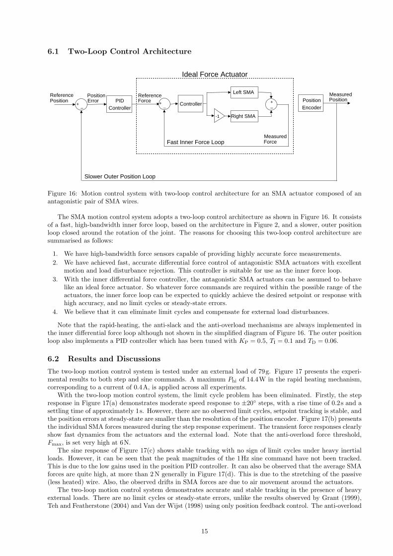
Figure 16: Motion control system with two-loop control architecture for an SMA actuator composed of anantagonistic pair of SMA wires.
The SMA motion control system adopts a two-loop control architecture as shown in Figure 16. It consistsof a fast, high-bandwidth inner force loop, based on the architecture in Figure 2, and a slower, outer positionloop closed around the rotation of the joint. The reasons for choosing this two-loop control architecture aresummarised as follows:
1. We have high-bandwidth force sensors capable of providing highly accurate force measurements.2. We have achieved fast, accurate differential force control of antagonistic SMA actuators with excellent
motion and load disturbance rejection. This controller is suitable for use as the inner force loop.3. With the inner differential force controller, the antagonistic SMA actuators can be assumed to behave
like an ideal force actuator. So whatever force commands are required within the possible range of theactuators, the inner force loop can be expected to quickly achieve the desired setpoint or response withhigh accuracy, and no limit cycles or steady-state errors.
4. We believe that it can eliminate limit cycles and compensate for external load disturbances.
Note that the rapid-heating, the anti-slack and the anti-overload mechanisms are always implemented inthe inner differential force loop although not shown in the simplified diagram of Figure 16. The outer positionloop also implements a PID controller which has been tuned with KP = 0.5, TI = 0.1 and TD = 0.06.
6.2 Results and Discussions
The two-loop motion control system is tested under an external load of 79g. Figure 17 presents the experi-mental results to both step and sine commands. A maximum Phi of 14.4W in the rapid heating mechanism,corresponding to a current of 0.4A, is applied across all experiments.
With the two-loop motion control system, the limit cycle problem has been eliminated. Firstly, the stepresponse in Figure 17(a) demonstrates moderate speed response to ±20 steps, with a rise time of 0.2s and asettling time of approximately 1s. However, there are no observed limit cycles, setpoint tracking is stable, andthe position errors at steady-state are smaller than the resolution of the position encoder. Figure 17(b) presentsthe individual SMA forces measured during the step response experiment. The transient force responses clearlyshow fast dynamics from the actuators and the external load. Note that the anti-overload force threshold,Fmax, is set very high at 6N.
The sine response of Figure 17(c) shows stable tracking with no sign of limit cycles under heavy inertialloads. However, it can be seen that the peak magnitudes of the 1Hz sine command have not been tracked.This is due to the low gains used in the position PID controller. It can also be observed that the average SMAforces are quite high, at more than 2 N generally in Figure 17(d). This is due to the stretching of the passive(less heated) wire. Also, the observed drifts in SMA forces are due to air movement around the actuators.
The two-loop motion control system demonstrates accurate and stable tracking in the presence of heavyexternal loads. There are no limit cycles or steady-state errors, unlike the results observed by Grant (1999),Teh and Featherstone (2004) and Van der Wijst (1998) using only position feedback control. The anti-overload
15

0 2 4 6 8 10 12 14 16 18−15
−10
−5
0
5
10
15
Ang
le (
deg)
Time (s)
ReferenceActual
(a)
0 2 4 6 8 10 12 14 16 180
1
2
3
4
5
For
ce (
N)
Time (s)
Left SMARight SMA
(b)
0 0.5 1 1.5 2 2.5 3 3.5 4−15
−10
−5
0
5
10
15
Ang
le (
deg)
Time (s)
ReferenceActual
(c)
0 0.5 1 1.5 2 2.5 3 3.5 40
1
2
3
4
5
For
ce (
N)
Time (s)
Left SMARight SMA
(d)
Figure 17: Experimental motion control results with two-loop control (with external load of 79g). (a) Positionstep response, and (b) its corresponding individual SMA forces. (c) Position tracking response at 1Hz, and(d) its corresponding individual SMA forces.
and rapid-heating mechanisms can protect the SMA actuator from overstressing and overheating of the wires,which other controllers in the literature do not.
7 Conclusions
A force control system has been presented that produces fast, accurate responses in an actuator consisting ofan antagonistic pair of SMA wires. The differential force control system consists of a PID differential controllerand three additional control elements — the anti-slack, the rapid-heating and the anti-overload mechanisms.The force response demonstrates the following characteristics:
1. Fast tracking with a high average force rate of 50Ns−1
2. Setpoint accuracy as high as 0.001N, which is 0.017% of the 6N output force range3. No limit cycles observed4. Actuator damage prevented with no overheating or overstressing of SMA wires5. Good external disturbance rejection
This paper also describes a position controller, which is formed by closing an outer position feedback looparound the force controller. This control system, in the presence of heavy dynamic loads, demonstrates highlyaccurate positioning, with no limit cycles and no measurable steady-state errors. However, based on the resultspresented, the position tracking speed of our two-loop controller is not as fast as the force tracking speed.
The results achieved in this research can be used as guidelines for enabling practical SMA actuator androbotic applications. Future research directions include implementing better control designs to further improve
16

the speed of response of the SMA actuator. We plan to investigate using larger thresholds in rapid heatingand the anti-overload mechanism. A more effective anti-overload scheme will also be investigated.
References
Ashrafiuon, H., Eshraghi, M., and Elahinia, M. H. (2006). Position Control of a 3-Link Shape Memory AlloyActuated Robot. J. Intelligent Material Systems & Structures, vol. 17, pp. 381–392.
Bergamasco, M., Dario, P., and Salsedo, F. (1990). Shape Memory Alloy Microactuators. Sensors & ActuatorsA: Physical, vol. 21, no. 1-3, pp. 253–257.
Choi, S. B., Han, Y. M., Kim, J. H., and Cheong, C. C. (2001). Force Tracking Control of a Flexible GripperFeaturing Shape Memory Alloy Actuators. Mechatronics, vol. 11, pp. 677–690.
Dickinson, C. A., and Wen, J. T. (1998). Feedback Control Using Shape Memory Alloy Actuators. J. IntelligentMaterial Systems & Structures, vol. 9, no. 4, pp. 242–250.
Dynalloy, Inc. (Last accessed 10 December 2007). Flexinol r© Technical Data.http://www.dynalloy.com/TechnicalData.html
Elahinia, M. H., and Ashrafiuon, H. (2002). Nonlinear Control of a Shape Memory Alloy Actuated Manipulator.J. Vibration & Acoustics, Transactions of the ASME, vol. 124, pp. 566–575.
Featherstone, R., and Teh, Y. H. (2004). Improving the Speed of Shape Memory Alloy Actuators by FasterElectrical Heating. Proc. 9th Int. Symp. Experimental Robotics, Singapore, June 18–21, paper ID 128.
Featherstone, R., and Teh, Y. H. (2005). A Shape Memory Alloy Actuator. International patent applicationno. PCT/AU2005/000154.
Featherstone, R., and Teh, Y. H. (2006). A Shape Memory Alloy Actuator. Australian patent application no.2005210682.
Fu, Y., Du, H., Huang, W., Zhang, S., and Hu, M. (2004). TiNi-based Thin Films in MEMS Applications: AReview. Sensors & Actuators A: Physical, vol. 112, no. 2-3, pp. 395–408.
Gorbet, R. B., and Russell, R. A. (1995). A Novel Differential Shape Memory Alloy Actuator for PositionControl. Robotica, vol. 13, pp. 423–430.
Grant, D., and Hayward, V. (1997). Controller for a High Strain Shape Memory Alloy Actuator: Quenchingof Limit Cycles. Proc. IEEE Int. Conf. Robotics & Automation, vol. 1, pp. 254–259.
Grant, D., and Hayward, V. (1997). Variable Structure Control of Shape Memory Alloy Actuators. IEEESystems and Control Magazine, vol. 9, no. 3, pp. 80–88.
Grant, D., and Hayward, V. (2000). Constrained Force Control of Shape Memory Alloy Actuators. Proc. IEEEInt. Conf. Robotics & Automation, vol. 2, pp. 1314–1320.
Grant, D. (1999). Accurate and Rapid Control of Shape Memory Alloy Actuators. Ph.D. Thesis, McGillUniversity.
Hunter, I. W., Lafontaine, S., Hollerbach, J. M., and Hunter, P. J. (1991). Fast Reversible NiTi Fibers for Usein Microrobotics. Micro Electro Mechanical Systems, 1991, MEMS ’91, Proc. ’An Investigation of MicroStructures, Sensors, Actuators, Machines and Robots’, pp. 166–170.
Ikuta, K., Tsukamoto, M., and Hirose, S. (1988). Shape Memory Alloy Servo Actuator System with ElectricResistance Feedback and Application for Active Endoscope. Proc. IEEE Int. Conf. Robotics & Automation,vol. 1, pp. 427–430.
Kohl, M. (2004). Shape Memory Microactuators. Springer-Verlag, Berlin Heidelberg.
Kuribayashi, K. (1991). Improvement of the Response of an SMA Actuator Using a Temperature Sensor. Int.J. Robotics Research, vol. 10, no. 1, pp. 13–20.
Liang, C., and Rogers, C. A. (1993). Design of Shape Memory Alloy Springs with Applications in VibrationControl. J. Vibration & Acoustics, vol. 115, pp. 129–135.
17

Madill, D. R., and Wang, D. (1998). Modeling and L2-Stability of a Shape Memory Alloy Position ControlSystem. IEEE Trans. Control Systems Technology, vol. 6, no. 4, pp. 473–481.
Moallem, M., and Lu, J. (2005). Application of Shape Memory Alloy Actuators for Flexure Control: Theoryand Experiments. IEEE/ASME Trans. Mechatronics, vol. 10, no. 5, pp. 495–501.
Mosley, M. J., and Mavroidis, C. (2001). Experimental Nonlinear Dynamics of a Shape Memory Alloy WireBundle Actuator. Trans. ASME, J. Dynamic Systems, Measurement & Control, vol. 123, no. 1, pp. 103–112.
Russell, R. A., and Gorbet, R. B. (1995). Improving the Response of SMA Actuators. Proc. IEEE Int. Conf.Robotics & Automation, vol. 3, pp. 2299–2304.
Teh, Y. H., and Featherstone, R. (2004). Experiments on the Performance of a 2-DOF Pantograph RobotActuated by Shape Memory Alloy Wires. Proc. Australasian Conf. Robotics & Automation, Canberra,Australia, Dec. 6–8.
Teh, Y. H., and Featherstone, R. (2005). Experiments on the Audio Frequency Response of Shape MemoryAlloy Actuators. Proc. Australasian Conf. Robotics & Automation, Sydney, Australia, Dec. 5–7.
Teh, Y. H., and Featherstone, R. (2007a). Accurate Force Control and Motion Disturbance Rejection for ShapeMemory Alloy Actuators. Proc. IEEE Int. Conf. Robotics & Automation, Rome, Italy, Apr. 10–14.
Teh, Y. H., and Featherstone, R. (2007b). Frequency Response Analysis of Shape Memory Alloy Actuators.Proc. Int. Conf. Smart Materials & Nanotechnology in Engn. Harbin, China, Jul. 1–4.
Teh, Y. H. (2007). Fast, Accurate Force and Motion Control of Shape Memory Alloy Actuators. Ph.D. Thesis,Dept. Information Engineering, The Australian National University, Canberra, Australia, (Submitted 31October 2007).
Troisfontaine, N., Bidaud, P., and Dario, P. (1997). Control Experiments on Two SMA Based Micro-Actuators.Proc. Fifth Int. Symp. Experimental Robotics, Spring-Verlag, pp. 490–499.
Van der Wijst, M. (1998). Shape Control of Structure and Materials with Shape Memory Alloys. Ph.D. Thesis,Technische Universiteit Eindhoven.
Van Humbeeck, J. (1999). Non-Medical Applications of Shape Memory Alloys. Materials Science & Engineer-ing A, vol. 273–275, pp. 134–148.
Waram, T. (1993). Actuator Design Using Shape Memory Alloys. T. C. Waram, 2nd (Metric) Edition, Ontario,Canada.
Zhong, Z. W., and Yeong, C. K. (2006). Development of a Gripper using SMA Wire. Sensors & Actuators A:Physical, vol. 126, pp. 375–381.
18