an architectural approach to mobility - the handover...
TRANSCRIPT

FESCA 2005 Preliminary Version
An Architectural Approach to Mobility - TheHandover Case Study ?
.
Cristovao Oliveira 1
Department of Computer ScienceUniversity of Leicester
Leicester, UK
Michel Wermelinger 2
Computing DepartmentThe Open UniversityMilton Keynes, UK
Jose Luiz Fiadeiro 3
Department of Computer ScienceUniversity of Leicester
Leicester, UK
Antonia Lopes 4
Dep. de InformaticaUniv. de Lisboa
Lisboa, Portugal
AbstractCOMMUNITY is a formal approach to software architecture. It has a precise, yet intuitivemathematical semantics based on category theory. It supports, at the methodological level,a clear separation between computation, coordination, and distribution (including mobil-ity). It provides a simple state-based language, inspired by Unity, for describing compo-nent behaviour. Finally, it addresses composition as a first class concern and accounts forthe emergence of global system properties from interconnections. This paper describes theapproach and tool support by modelling essential aspects of the GSM handover protocol.We also sketch a framework that we are implementing for the distributed execution of such
This is a preliminary version. The final version will be published inElectronic Notes in Theoretical Computer Science
URL: www.elsevier.nl/locate/entcs

Oliveira
specifications, using Klava, a Java library for mobile agent systems based on tuple spacesby our project colleagues from Firenze.
Key words: Architecture, composition, (dynamic) configuration,connector, coordination, distribution, mobility, superposition.
1 Introduction
COMMUNITY provides, like Darwin [10], Wright [1], or LEDA [3], among others,a formal approach to software architecture. It has several advantages over otherapproaches, the main one being a precise mathematical semantics: architectures arenot just depicted through lines and boxes; they are diagrams in the sense of categorytheory [5], involving explicit superposition and refinement relationships betweenarchitectural components. This graphical semantics (in both the mathematical andvisual sense) mirrors closely and intuitively the design of the architecture. Thecategorical semantics has also allowed us to study connectors in a deep, rigorous,and language-independent way [6]. In particular, we have defined higher-orderconnectors and shown how they can be used to put together complex interactions(e.g., an encrypted compressed asynchronous communication) from simpler onesin a systematic way [9].
In addition, COMMUNITY describes component behaviour with a parallel pro-gram design language that is at a higher level of abstraction and is more convenientto use than the process calculi employed by most formal approaches to software ar-chitecture. The combination of this state-based language with the graph-based se-mantics of architecture allowed us to define run-time reconfiguration in an intuitiveand formal way using typed graph transformation rules. The typing corresponds toa simple notion of architectural style that is preserved during reconfiguration [16].
Like most architectural approaches, COMMUNITY enforces a strict separationbetween computation and coordination. More recently, we have extended the ap-proach with a small set of semantic concepts and syntactical constructs in orderto include a distribution dimension that is kept separate from the other two [8].The granularity of distribution is very fine in order to provide maximum flexibil-ity: the execution of an action may be distributed over many different locations; ateach location, it performs whatever computations are prescribed according to theavailable resources, and communicates with its environment through the communi-cation channels that are in touch with the location. Changes to locations correspondto mobility of data or code. So far we have illustrated our approach with small ex-amples. The goal of this paper is to show how it applies to larger examples taken
? This is an extended version of a short paper presented at WICSA’04) [14]1 Email: [email protected] Email: [email protected] Email: [email protected] Email: [email protected]
2

Oliveira
from real applications in which distribution and mobility are key concerns. For thispurpose, we chose to model the GSM handover protocol. Due to space constraints,we only show a fragment; the complete details are given in [12].
In order to show how all the features of COMMUNITY can be used in practice,we have been developing in the last few years a workbench [13] as a proof ofconcept of the formal framework. The Workbench provides a graphical integrateddevelopment environment to write, run, and debug designs and to draw softwarearchitectures (configurations). This paper provides a more detailed description ofthe tool than previously available, in particular of the features recently added tocover the mobility dimension. These features are explored in the modelling of theGSM handover.
The structure of this paper is as follows. We start with the description of thehandover protocol as we use it. In Section 3 we present an informal review of COM-MUNITY. Formal definitions can be found in the papers cited above. Examples aretaken from the case-study. Next, we describe the COMMUNITY Workbench and thearchitecture description language. In Section 5 we show how the handover protocolcan be modelled with COMMUNITY and tested with the workbench. We finish thepaper with some concluding remarks.
2 Handover Protocol
As an example of mobile network, we consider the Public Land Mobile Networkthat implements the world-wide adopted GSM network—a living and evolvingwireless communications standard. Specifically, we concentrate on the handoverprocess [15], which is what controls the dynamic topology of the network.
In order to illustrate the approach as clearly as possible, we concentrate on thefollowing nodes of the GSM network:• Mobile Station (MS): This node is made up of the Subscriber Identification
Module (SIM) and the Mobile Equipment. The SIM is a separate physical entitycontaining all information regarding the subscription. The Mobile Equipment isthe piece of hardware that enables radio communication with the system.
• Base Station System: This node is composed of some Base Transceiver Stations(BTS) and one Base Station Controller (BSC). The BTS is the radio equipmentwhose main task is the radio communication with the MS’s. Each BTS coversa cell with transmitted radio wave. The BSC controls the communication andsupervises the behaviour of all its underlying BTS’s.
• Mobile Services Switching Center (MSC): This node sets up, supervises, andreleases calls of some BSC’s. It connects the calls within the GSM networkand/or actuates as a gateway to the Public Switched Telephone Network or tosome other networks.
The handover is a process required for ensuring the continuity of a call of a MSmoving across a BTS cell boundary; without such a process the communicationcould be terminated because of the limited range of the BTS. As described in [15],
3

Oliveira
the purpose of the handover procedure is to move data and control channels of thecall from the BSC currently communicating with the MS (what we call the ‘old’BSC) to a BSC in another cell (the ‘new’ BSC). When the MS is busy (during acall), the decision about which cell is the best for the dedicated connection is doneby the BTS and the BSC. This procedure consists in evaluating the received radiosignal measurements from the MS.
In the GSM network, there are three types of handover depending on the BTS’sinvolved [17]:• Intra-BSC Handover: In this case the handover process concerns two BTS’s
belonging to the same BSC.• Inter-BSC Handover: The handover process concerns two BTS’s but of two
different BSC’s controlled by the same MSC.• Inter-MSC Handover: The handover process in this case is between two BTS’s
belonging to different BSC’s controlled by different MSC’s.
Fig. 1. Handover procedure
In this paper, we focus on the Inter-BSC handover process (see Figure 1) dueto the fact that this type of handover is simpler than the third one but neverthelessinvolves all the steps required in a complete handover process. These steps can bedescribed as follows:• Handover request : The old BSC detects the necessity of the handover with
the last received information from its BTS’s, suspends the transmission of allmessages except for the radio resource management sub-layer messages with theMS, and sends the message ‘handover request’ to the MSC. The MSC forwardsthis message to the new BSC (step 1.a).
• Handover command : The new BSC prepares its BTS for receiving the newMS (step 1.b). Then, the new BSC initiates the handover by transmitting thehandover command message to the MS through the old BSC (step 2). This steppermits the MS to locate the radio channel of the new BTS/BSC.
4

Oliveira
• Handover bursts : Upon receipt of the handover command message, the MSdisconnects the old radio channels and initiates the establishment of lower layerconnections in the new radio channels. In order to establish these connectionsthe MS sends a handover burst message to the new BSC (step 3) and, whensuccessful, the transmission suspended with the old BSC is re-established againbetween the MS and the new BSC through its BTS.
• Handover complete : Finally the MS sends the handover complete message tothe old BSC through the new BSC (step 4). By receiving this message, the oldBSC resumes all normal operations and releases the old radio channels on itsBTS (step 5).
3 COMMUNITY
COMMUNITY [5] is a parallel program design language initially developed to showhow programs fit into Goguen’s categorical approach to General Systems Theory.The language and its framework have been extended to provide a formal platformfor architectural design of open, reactive, and reconfigurable systems.
COMMUNITY designs are in the style of UNITY programs [4], but they alsocombine elements from IP [7]. However, COMMUNITY has a richer coordinationmodel and, even more important, it requires interaction between components to bemade explicit. In this way, the coordination aspects of a system can be separatedfrom the computational ones and externalized, making explicit the gross configu-ration of the system in terms of its components and the interactions between them.Each configuration can be transformed into a single, semantically equivalent, de-sign that captures the behaviour of the whole system as it emerges from the com-ponents and their interconnections.
In order to model systems that are location-aware, a recent extension [8] ofCOMMUNITY was developed that adopts an explicit representation of the spacewithin which movement takes place, but does not assume any specific notion ofspace. In this way, Computation, Coordination, and Distribution/Mobility are ex-plicitly separated as architectural dimensions. The remaining of this section ex-plains how this separation is achieved.
In COMMUNITY, every design is described in terms of a set of channels (de-clared as input, output or private) and a set of actions (shared or private).• Input channels are used for reading data from the environment; the design has no
control on the values received in such channels. Output and private channels arecontrolled locally by the design. Output channels allow the environment to readtheir values.
• Shared actions represent possible interactions between the design and the envi-ronment; private actions represent internal computations in the sense that theirexecution is uniquely under control of the design.
The computational aspects are described in COMMUNITY through the transforma-tions operated by the actions over the channels. Each action is composed by a guard
5

Oliveira
and a set of assignments over the private and output channels. A collection of datatypes is used for structuring the data that the channels transmit and for defining theoperations that perform the computations required on the assignments. If an actionhas no assignments, we represent its body by the keyword skip. Figure 2 showsthe design of the mobile station (cellular phone) for the handover case study. Thisdesign has, two input channels (inMsg1, inMsg2), two output channels (outMsg1,outMsg2), and two pairs of actions for communication (send1 and receive1, send2and receive2). These channels and actions will be used to the communication withthe current and the candidate BSCs. To reflect the fact that a sending should alwaysprecede a receipt we add a private channel (sc). This private channel is used in theguards of both actions (switching between true and false). The expression “X oneofT” assigns a random value of type “T” to channel “X”.
In order to reflect the separation between computation and coordination, thedefinition of individual components of a system is completely separated from thedefinition of the interactions between these components. The model of interactionbetween designs is based on action synchronization and exchange of data throughinput and output channels. These are standard means of interconnecting softwarecomponents. What distinguishes COMMUNITY from other parallel program designlanguages is the fact that such interactions between components have to be madeexplicit by providing the corresponding name bindings; no implicit interaction canbe inferred from the use of the same name in different designs. We can witnessthree kinds of interaction between two components:
(i) A connection of an input channel of one design with an output channel of theother;
(ii) A connection of an input channel of one design with an input channel of theother;
(iii) Synchronization between one action from each design.
COMMUNITY was extended having in mind the need to provide support forthe description of the distribution and mobility aspects of systems in a way thatis completely separated from the computational and interaction aspects. In or-der to support this three-way separation of concerns, designs were extended to belocation-aware by associating their “constituents”—private and output channels,and actions—with “containers” that can move to different positions. Hence theunit of mobility, that is the smallest constituent of a system that is allowed to move,is fine-grained.
More precisely, designs have a set of location variables over a special type Locthat describes the possible values that constitute the “space of mobility”. The datasort Loc models the positions of the space in a way that is considered adequatefor the particular application domain in which the system is or will be embedded.Each output channel, private channel, and action, is assigned to a set of locationvariables:• Each local channel x is associated with a location variable l. We make this as-
signment explicit by writing x@l in the declaration of x. The value of l indicates
6

Oliveira
the current position of the space where the values of x are made available. Amodification in the value of l entails the movement of x as well as of the otherchannels and actions located at l;
• Each action g is associated with a set of location variables meaning that theexecution of action g is distributed over those locations. In other words, theexecution of g consists of the synchronous execution of the parts of it in each ofthese locations.
Location variables can be declared as input or output in the same way as channels.Input location variables are read from the environment and cannot be modified bythe design and, hence, the movement of any constituent located at an input locationvariable is under the control of the environment. Output location variables can onlybe modified locally through assignments performed within actions and, hence, themovement of any constituent located at an output location variable is under controlof the design. In Figure 2 there is an output location variable lms, and the movementof the local channels and the actions are under control of the design. The privateaction move changes the value of the location variable.
Fig. 2. A Distributed Design
Figure 3 shows the details of an interaction, where input channels and inputlocations are depicted by inward triangles, output channels and output locationsby outward triangles, and actions by circles. Note that only input/output channelsand shared actions appear, because private channels and private actions are notused in interactions. In the Figure we show the interaction between the MS andms measure designs. For instance this interaction consists only to the connectionbetween two location variables (respectively lms and lm) and it means that thems measure is always co-located with the MS. In Section 5.4 this is explained inmore details.
Due to the introduction of the distribution/mobility dimension two new binaryinteractions emerge:
7

Oliveira
Fig. 3. Interactions
• A connection of an input location variable of one design with an output locationvariable of another;
• A connection of an input location variable of one design with an input locationvariable of another.
The relevant properties of the mobility space introduced upon are captured by twobinary relations over the domain. First the relation touch defines that two posi-tions in the space are “in touch” with each other. Coordination among componentstakes place only when all the locations of all the actions involved in a synchro-nization are “in touch”. We assume that touch is reflexive and symmetric. Thesecond relation reach means that one position is reachable from another, and isassumed to be reflexive. Movement to a new position is possible only when thisposition is reachable from the current one, i.e., a location variable can take a newvalue if this value is of a location reachable from the current position representedby the current value of the location variable. Figure 4 shows the definitions usedfor the case study: locations are represented by pairs of integers; two locations arein touch if they are adjacent; any location is reachable from any other. To definethe relations we use mathematical expressions. For instance ‘|’ is the disjunctionand ‘&’ the conjunction. Due to the relation ‘in touch’ being symmetric and re-flexive the workbench rewrites the correspondent expression in the second part ofthe editor (Reflexivity for the relation ‘Reach’).
q a 2a parte e o fecho reflexivo (e simetrico) da definicao do utilizadorThe semantics of a system configuration can be obtained through the colimit
of the system, which corresponds to computing the parallel composition of theprocesses and interactions involved. By internalizing all the interactions, the col-imit delivers a design for the system as a whole. More generally, colimits in COM-MUNITY are obtained as follows:• Channels and locations involved in each i/o-communication established by the
8

Oliveira
Fig. 4. Locations
configuration are amalgamated.• Every set of actions that are synchronized is represented by a single action whose
occurrence captures the joint execution of the actions in the set. The transfor-mations performed by the joint action are distributed over the locations of thesynchronized actions. Each located action is specified by the conjunction of thespecifications of the local effects of each of the localized actions.
We show in Figure 5 part of the colimit generated for the case study (see Sec-tion 5). In particular, the figure shows an action clean 1handoverCommand 13distributed over two locations, given by location variables lms 0 and lmsc 13.
The three following rules express the restrictions on the interactions that makean architecture a well-formed configuration and for which the existence of colimitscan be ensured:• An output channel or location of a component cannot be connected with output
channels or locations of the same or other components (even indirectly);• Private channels and private actions cannot be involved in the connections.• Indirect synchronization of actions belonging to the same design is forbidden,
because this entails their execution at the same time.
4 COMMUNITY Workbench
The COMMUNITY Workbench [13] implements directly over Java the construc-tions of coordination and distribution that give semantics to COMMUNITY as anarchitectural description language. Although COMMUNITY is independent of theactual data types used, the Workbench provides a fixed set of types: integer andreal numbers, booleans, lists, arrays, records, and enumerations. The workbenchalso includes an export utility to save the whole architecture or just some connec-tors as a textual specification that can be easily read and understood without the
9

Oliveira
Fig. 5. Colimit
tool as will be explained in the next section. The workbench is available from theCOMMUNITY web site (www.fiadeiro.org/jose/CommUnity).
The current version of the tool (1.2) allows the user to:
(i) Specify the Loc type and the relations touch and reach: The location typeis defined in terms of the pre-defined types (e.g., as a record of two integersto represent a 2 dimensional space). The relations are defined as booleanexpressions with both parameters of location type.
(ii) Write COMMUNITY designs: The user may write new designs or edit existingones.
(iii) Define graphically architectural connectors: In connector diagrams the usermay do the same he can do in the architecture diagram (see step IV below),except for adding and deleting connectors. In the diagram of a connector, eachnode is uniquely numbered and must be an instance of an existing design.Connectors must have a star topology, the glue being in the center.
(iv) Define graphically the architecture, with connectors, and calculate its colimit:In the architecture, the user may add and delete nodes, arcs and connectors,drag nodes around to change the diagram layout, double-click on an arc orselect some nodes to invoke a graphic link editor to visualize and/or to set the
10

Oliveira
Fig. 6. Refinement in the Workbench
interactions between the selected nodes. The user can make direct connectionsbetween channels and locations as well as synchronizations between actionsof different nodes. The editor presents to the designer all the actions, inputand output channels of the selected nodes as was shown in Figure 3. Theworkbench detects invalid bindings—(in)direct sharing of output channels orlocation variables, or synchronization of actions of the same node. The usermay add the connectors created in step III to the main architecture. This isdone by explicitly defining which components refine which roles of the addedconnectors. Figure 6 shows how the instance of the MS design refines themsroleinfo role of the BTS connector (to be explained in Section 5), i.e., howthe channels and actions of the role are mapped to those of the component.Notice that, whereas in the composition of components output channels areconnected to input channels, in refinement output channels must be mappedto output channels. Components are represented by rectangles, connectors byoval shapes, and direct links by lines with small black squares.
(v) Run a design (in particular the colimit of the configuration): Before runninga design, the user has to provide the initial values for all channels and locationvariables, and to choose which channels, location variables and actions shouldbe traced. In Figure 7 we show the initialization window. By default, numbersare initialized with zero, booleans with false, and only output channels andlocation variables are traced. The trace gives great flexibility to test severalscenarios. Shared actions can be explicitly selected for execution by the useror automatically by the tool, in fair or random mode. Private actions are al-ways selected in a fair mode. There are also three choices for the value ofany input channel that is not connected to an output channel: 1-The same as
11

Oliveira
Fig. 7. Initialisation
in the previous execution step; 2-A random value; 3-Set by the user. Duringthe trace the user can track the location variables: after each step, the currentvalue of each location variable is shown, as well as the touch and reachrelations between the location variables. We show in Figure 8 a possible stateof the location variables when running the case-study. The black arrows showthat the target location is reachable from the source location and the whitelines show the locations are in touch.
Fig. 8. Locations Track
CommUnity architectures and connectors described in the WB can be saved astextual specifications. The language that is used is like most Software Architectureapproaches. We propose an Architecture Description Language to describe COM-MUNITY architectures. This language is inspired mainly by Armani [11]. Moreprecisely, the template of our architecture language is as shown in Figure 9. Forillustration, the connectors presented in this paper are described using this notation(More precisely the subsection 5.3).
5 Handover in COMMUNITY
We will now produce the conceptual model, following the description of the han-dover protocol given in Section 2. The proposed development consists of fivephases to be applied in the order shown in Figure 10:
(i) Architectural entities We operate a decomposition of the system in terms ofdesigns and interactions (links and/or connectors). A black-box computationalentity is represented as a single design, and a relationship between designs is
12

Oliveira
architecture name {loc = data typebt (x,y) = boolean expression over x and yreach (x,y) = boolean expression over x and ycomponents
design name 1design name N
connectorsconnector name {
gluedesign name
rolesdesign roleName 1design roleName K
configurationinstd 1, instd L: designNameattachments {
instd I.idI - instd J.idJ}
}configuration
instd 1, instd M: designNameinstc 1, instc P: connectorNameattachments {
instd I.idI - instd J.idJ}refinement instc I.roleName to instd J {
idI to idJ}
}
Fig. 9. Architecture Specification Template
Fig. 10. Development
represented through an interaction.
(ii) Computation We describe in detail each identified design from the previousphase. That is, the private as well as the shared constituents (input/output/private
13

Oliveira
channels and shared/private actions) are completely specified.
(iii) Coordination Each identified interaction has to be classified either as a simplelink between two designs or a connector, which can includes some behaviour.In order to specify a connector the behaviour should be encapsulated in a glue,and a role has to be defined for each type of participant. In some cases it isnecessary to go back to the computation phase based on intermediate resultsfrom this phase.
(iv) Distribution This phase starts by checking the possible topological distribu-tion for each design and glue resulting from the previous phases. In case of re-quired distribution, the corresponding design or glue has to be extended/adaptedwith appropriate location variables and actions dealing with them (e.g., to ex-press mobility). Due to the new requirements some existent actions can alsobe distributed over locations. Finally, to handle the topological distributionof the real system, new connectors dealing only with locations can be createdfrom scratch.
(v) Execution The architecture is executed with different initial values in order totest it. In the current version of the workbench, the execution of the specifiedarchitecture is centralized, in the sense that it is simulated by the executionof the generated colimit. In the future we will make available a distributedexecution mode: the location values will be mapped to physical hosts and thephysical mobility will be real (for more details see Section 5.5).
In the following we describe the handover process using COMMUNITY and theworkbench, applying the development steps described above. For this descriptionwe assume a small system with only one MS, two BTS/BSC’s and one MSC, as it issufficient for reflecting all features of a typical handover. Moreover, in our systemspecification we assume that the MS is continuously communicating with a BSC,because if the MS is idle no handover would be required. The handover is triggeredby the current BSC, and it initiates the process. In our model the relation touchplays an important role. That is, the MS moves around and it can only receive themeasurements from both BTS’s when it is in touchwith them. Then each time theMS receives both measurements, it sends them to the current BSC, which verifiesif it controls the BTS closest to the MS. If this is not the case it begins the handoverprocess. Although the handover process can fail in a real system, we assume nofailure for this model because our goal is to model the architecture, focuses on theseparation of dimensions. The externalization of the measurements’ process andthe handover to connectors shows to be a first good step, because for example itpermits us to detect where the model must explicitly evolve to include scalability.The evolution of the model to include failure is a possibility for future work.
5.1 Architecture entities
By analyzing the case study, we discover two different kinds of computation foreach entity—namely communication and measurements, and we propose therefore
14

Oliveira
to distinguish them in different elements in the architecture. Afterwards we namedas layers the two different kinds of computation.• MS: We describe the MS with two designs. The first one, denoted MS, in-
cludes the computation related to the communication. The second one, denotedms measure, encapsulates the computation reflecting the reception and sendingof any measurements.
• BSC: Similarly, we capture the BSC using two designs, denoted by BSC andbsc measure.
• MSC: We propose just one design, named MSC, to deal with the communica-tion.
• BTS: Three connectors are associated with this entity, that we refer to as BTS,bts measure, and btsmeasure. The distinction between the last two connectorswill be described in the subsection 5.3.
• Handover: In order to externalize the handover process, we define this entity asan interaction represented by a connector called Handover.
Figure 11 depicts the organization of the different entities of the Handover ar-chitecture. The elements of the architecture are disposed in order to visualize thetwo layers referred before. Above are all the components and connectors related tothe treatment of the measurements.
Fig. 11. The architecture in the Workbench
5.2 Computation
As stated before, this phase details each of the previously identified computationalentities, the designs. We only show and discuss the details of the ms measure
15

Oliveira
and the bsc measure designs. To describe each design, we refer to the syntax ofCOMMUNITY (see Section 3). The design MS is already explained in section 3and shown in Figure 2.
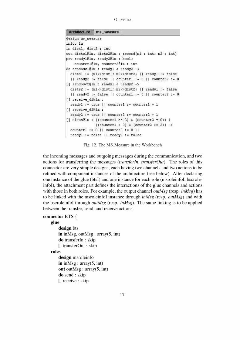
ms measure:The ms measure receives the measurements from the two BTS’s through the
connectors btsmeasure’s, then sends them to the current BSC (respective bsc measure).For this purpose, it uses one input channel (dist1 and dist2) for each btsmeasure,and one output channel (dist1dist2) to make the measurements available. Like theMS design, for each of the two considered BSCs we have one action for sendingthe measurements (sendbsc1 and sendbsc2) and another one for receiving them (re-ceive d1 and receive d2). Finally, for controlling the sequence of its actions, someprivate channels are required (the ready and counter channels). For executing theaction sendbsc1 or sendbsc2 the private channels ready1 and ready2 must have thevalue true. This only happens if the ms measure has received both measurementsexecuting the actions receive d1 and receive d2. But the ms measure must avoid toreceive a measurement twice, so the counter’s are used for that purpose. If actionreceive d1 (and the same for receive d2) is executed twice before the other one,then action clean is executed and the counter and ready channels are re-initialized.This leads to the COMMUNITY design shown in Figure 12.
bsc measure:The bsc measure receives the measurements from its corresponding BTS (trough
the respective connector bts measure), then verifies if the best measurement corre-sponds to its BTS. The result of the verification is send to the component BSC. Forthis purpose, it uses one input channel (distdist2) and one action (receive distdist2)to receive the measurements. The result is made available with the output chan-nel newId. As for the ms measure this design results from the abstraction of thetreatment of the measurements and the communication into different components.And finally the bsc measure has an boolean input channel communication that isused as guard to the action which is used to receive the measurements. There is nosense to receive the measurements if this BSC is not the current one used on thecommunication.
5.3 Coordination
This phase details each of the interactions identified in Section 5.1. That is, for eachconnector, its glue, roles, and attachments are completely defined. We show anddiscuss the details of the BTS entity. The separation of the two layers is representedby different connectors.
BTS:This is a binary connector relating the MS instance to a BSC instance. The glue
part of this connector is a design with two input channels (inMsg and outMsg) for
16
Oliveira
Fig. 12. The MS Measure in the Workbench
the incoming messages and outgoing messages during the communication, and twoactions for transferring the messages (transferIn, transferOut). The roles of thisconnector are very simple designs, each having two channels and two actions to berefined with component instances of the architecture (see below). After declaringone instance of the glue (btsI) and one instance for each role (msroleinfoI, bscrole-infoI), the attachment part defines the interactions of the glue channels and actionswith those in both roles. For example, the output channel outMsg (resp. inMsg) hasto be linked with the msroleinfoI instance through inMsg (resp. outMsg) and withthe bscroleinfoI through outMsg (resp. inMsg). The same linking is to be appliedbetween the transfer, send, and receive actions.
connector BTS {glue
design btsin inMsg, outMsg : array(5, int)do transferIn : skip[] transferOut : skip
rolesdesign msroleinfoin inMsg : array(5, int)out outMsg : array(5, int)do send : skip[] receive : skip
17

Oliveira
design bscroleinfoin inMsg, outMsg : array(5, int)do transferIn : skip[] transferOut : skip
configurationbtsI: btsmsroleinfoI: msroleinfobscroleinfoI: bscroleinfo
attachments {btsI.outMsg - msroleinfoI.inMsgbtsI.inMsg - msroleinfoI.outMsgbtsI.transferOut - msroleinfoI.sendbtsI.transferIn - msroleinfoI.receivebtsI.inMsg - bscroleinfoI.inMsgbtsI.outMsg - bscroleinfoI.outMsgbtsI.transferIn - bscroleinfoI.transferInbtsI.transferOut - bscroleinfoI.transferOut
}}
In order to use this connector with the MS and BSC designs, the role msrole-infoI and the role bscroleinfoI are refined with a MS design instance and a BSCdesign instance, respectively. Part of the refinement is shown in Figure 6.
refinement bts.msroleinfoI to MS {inMsg to inMsg1outMsg to outMsg1send to send1receive to receive1
}refinement bts.bscroleinfoI to BSC {
inMsg to inMsgoutMsg to outMsgtransferIn to transferIntransferOut to transferOut
}
Handover:This connector externalizes all the handover process. It has three actions re-
lated to the handover process. The actions handoverReqBSC1 and handoverRe-qBSC2 initiate the handover. The action handoverCommand can be selected afterthe execution of one of the previous actions, because the output channel hand usedin the guard remains true. This action is the handover core of our model, becauseit makes an exchange of values between the two BSC’s through the two output
18

Oliveira
channels communicationBSC1 and communicationBSC2.
5.4 Distribution
As the topological distribution is obviously crucial in this application, any attemptto abstract it away would not be realistic. Following our development steps, onthe basis of the resulting specification, we propose to enrich it with the requireddistribution features. We consider as illustration two designs and two connectors,namely the ‘Mobile’ MS, and the ‘Location-aware’ ms measure, bts measure andbtsmeasure. We recall that Figure 4 shows the definition of type Loc and its binaryrelations adopted for this case study.
Mobile MS:This design has already been shown in Figure 2. All its constituents, channels
and actions move together around in a random way.
ms measure:Due to the fact that ms measure is always co-located with MS, this design has
an input location variable (lm) that is connected to the output location variable ofthe MS, as shown in Figure 3. Moreover, all its channels and actions are at locationlm, in the same way as for the MS.
btsmeasure:This unary connector sends to ms measure the measurement based on the loca-
tion of its glue and the location it receives from the ms measure (which is the sameas the MS location), but only when their location variables are “in touch ”. Theglue of the connector is composed of: an output location variable holding its loca-tion, an input location variable for reading the current location of the ms measurewhen in touch, and an action with an adequate output channel for sending thecomputed distance to the ms measure.
bts measure and Handover:The connector bts measure has an input location variable in its glue, that must
be initialized with the value of the output location variable of the glue of the lastconnector, because they are related to the same BTS entity. When the MS is “intouch” with the last connector, it must be in touch with the related one. The han-dover connector has one output location variable and all the constituents are locatedin the respective location variable.
5.5 Execution
In the current version of the workbench, the execution phase is centralized, in thesense that it is simulated by the execution of the generated colimit. Figure 7 shows
19

Oliveira
the editor where the channels and locations can be initialized before the user cantest the desired scenario. In the same editor he can choose which channels he wantsto see evolving during the execution steps. While the colimit’s execution is traced,the state of the system after each execution step can be analyzed with the currentvalues of the channels.
We now present a summary of the architecture for distributed execution that weare currently implementing in the Workbench, based on the Klava package [2]. Thislibrary for mobile agent systems based on tuple spaces contains some facilities forspecifying hosts, and logical and physical locations. The communication betweenhosts is encapsulated in a sub-layer, and because of that, we can abstract from thecommunication implementation layer. The Klava package has support for nodesthat are located on the hosts and support for execution of processes on the nodes.
The specification of the architecture is distributed over a set of hosts, where wegive an important role to one host, called the global host, which has the centralizedknowledge of the architecture in COMMUNITY.
We define a mapping from the location values of the location types to the exis-tent hosts. The touch and reach relations are implemented directly in Java overthe location type.
The global host stores the connections (shared channels and synchronized ac-tions) of the COMMUNITY architecture, the values of the location variables, and allchannels that are not located at any location variable. The global host also storesthe input channels that are not connected to any output channel. Moreover, it hasa process, “globalInterpreter”, runnning. This process knows all the COMMUNITY
architecture and uses a fair algorithm for deciding which actions it will try to exe-cute at each step.
We assume a fixed number of hosts. Each host stores all channels and actionslocated in location variables whose values map to that host.
All hosts (including the global one) have a running process denoted “localInter-preter”. This process is in a loop, waiting for messages from the “globalInterpreter”which ask for values of local channels, for the verification of guards of the local ac-tions, or for the execution of local actions. We are implementing the necessarysequential steps for the communication between the global and the other hosts, andwe use the facilities of Klava of mobility of tuples between hosts for moving thechannels and actions during the execution of the system.
6 Concluding Remarks
In this paper, we have illustrated how COMMUNITY supports architectural mod-elling of applications that need to be location aware. The semantic and syntacticprimitives of COMMUNITY were shown to be expressive enough to model mobilesystems as we know them in reality. The Workbench proved useful in detectingsome errors in our initial, hand-written models. In particular, the trace facilitiesand the graphical depiction of the co-located channels and actions, and of the cur-rent “in touch” relationships, were found to be quite useful to animate the model
20

Oliveira
and to find deadlocks. In summary, we feel that COMMUNITY and the Workbenchare useful to anyone wishing to define and animate executable architectural modelsof distributed and mobile systems at a higher level of abstraction than other formalapproaches based on process calculi.
Currently we can only simulate the execution of the generated colimit. But soonwe expect to test, with the case-study model, the distributed execution implemen-tation, in order to make the approach scalable.
Acknowledgements
This research was partially supported through the IST-2001-32747 Project AGILE- Architectures for Mobility. The work of Cristovao Oliveira was supported byFundacao para a Ciencia e Tecnologia through the PhD Scholarship SFRH/BD/6241/2001.We thank Jose Aires, Mario Costa, Brian Pluss, and Frederico Palma for having im-plemented several parts of the Workbench.
References
[1] R. Allen and D. Garlan. A formal basis for architectural connection. ACM TOSEM,6(3):213–249, July 1997.
[2] L. Bettini, R. D. Nicola, and R. Pugliese. Klava: a Java framework for distributed andmobile applications. Software–Practice and Experience, 2002.
[3] C. Canal, E. Pimentel, and J. M. Troya. Specification and refinement of dynamicsoftware architectures. In Software Architecture, pages 107–125. Kluwer AcademicPublishers, 1999.
[4] K. M. Chandy and J. Misra. Parallel Program Design—A Foundation. Addison-Wesley, 1988.
[5] J. L. Fiadeiro. Categories for Software Engineering. Springer-Verlag, 2004.[6] J. L. Fiadeiro, A. Lopes, and M. Wermelinger. A mathematical semantics for
architectural connectors. Generic Programming, LNCS Springer(2793):190–234,2003.
[7] N. Francez and I. Forman. Interacting Processes. Addison-Wesley, 1996.[8] A. Lopes, J. Fiadeiro, and M. Wermelinger. Architecural primitives for distribution
and mobility. In Proc. 10th Symposium on the Foundations of Software Engineering,pages 41–50. ACM Press, 2002.
[9] A. Lopes, M. Wermelinger, and J. Fiadeiro. Higher-order architectural connectors.ACM Trans. on Software Eng. Methodology, 12(1):64–104, Jan. 2003.
[10] J. Magee, N. Dulay, S. Eisenbach, and J. Kramer. Specifying distributed softwarearchitectures. In Proceedings of the Fifth European Software Engineering Conference,Barcelona, Sept. 1995.
[11] R. T. Monroe. Capturing software architecture design expertise with Armani.Technical Report CMU-CS-98-163, School of Computer Science, Carnegie MellonUniversity, Oct. 1998.
[12] C. Oliveira. GSM system - handover. Appendix I of Deliverable 4.2 of the AGILEproject, 2003.
21

Oliveira
[13] C. Oliveira and M. Wermelinger. The community workbench. In ICSE ’04:Proceedings of the 26th International Conference on Software Engineering, pages709–710. IEEE Computer Society, 2004.
[14] C. Oliveira, M. Wermelinger, J. Fiadeiro, and A. Lopes. An architectural approach tomobility - the handover case study. In Proc. of the 4th Working IEEE/IFIP Conferenceon Software Architecture, pages 305–308. IEEE Computer Society Press, 2004.
[15] F. Orava and J. Parrow. An algebraic verification of a mobile network. In ProtocolSpecification, Testing, and Verification X, pages 275–291, Uppsala University,Department of Computer Systems, North-Holland, 1990.
[16] M. Wermelinger and J. L. Fiadeiro. A graph transformation approach to run-timesoftware architecture reconfiguration. Science of Computer Programming, 44:133–155, 2002.
[17] GSM System Overview, volume rev. no. 100. APIS Technical Training AB, Sweden,apis training & seminars edition, 1998. [email protected].
22