an approach for the semi-automated derivation of uml...
TRANSCRIPT

An Approach for the Semi-automated Derivation ofUML Interaction Models from Scenario-based Runtime Tests
Thorsten Haendler, Stefan Sobernig and Mark StrembeckInstitute for Information Systems and New Media
Vienna University of Economics and Business (WU Vienna), Austria{firstname.lastname}@wu.ac.at
Keywords: Test-based Documentation, Scenario-based Testing, Test-Execution Trace, UML Interactions, UML SequenceDiagram
Abstract: Documenting system behavior explicitely using graphical models (e.g. UML activity or sequence diagrams)facilitates communication about and understanding of software systems during development or maintenance.Creating graphical models manually is a time-consuming and often error-prone task. Deriving models fromsystem-execution traces, however, suffers from the problem of model-size explosion. We propose a model-driven approach for deriving behavior documentation in terms of UML interaction models from runtime testsin a semi-automated manner. Key to our approach is leveraging the structure of scenario-based tests for modeland diagram derivation. Each derived model represents a particular view on the test-execution trace. This way,one can benefit from derived graphical models while making the resulting model size manageable. In thispaper, we define conceptual mappings between a test-execution trace metamodel and the UML2 metamodel.In addition, we provide means to turn selected details of test specifications and testing environment into viewson the test-execution trace (scenario-test viewpoint). The feasibility of our approach is demonstrated by aprototype implementation (KaleidoScope), which builds on an existing software-testing framework (STORM)and model transformations (Eclipse M2M/QVTo).
1 INTRODUCTION
Scenarios describe intended or actual behavior ofsoftware systems in terms of action and event se-quences. Notations for defining and describing sce-narios include different types of graphical modelssuch as UML activity and UML interaction models.Scenarios are used to model systems from a user per-spective and ease the communication between differ-ent stakeholders (Jacobson, 1992; Jarke et al., 1998;Carroll, 2000). As it is almost impossible to com-pletely test a complex software system, one needs aneffective means to select relevant tests, to express andto maintain them, as well as to automate tests when-ever possible. In this context, scenario-based testingis a means to reduce the risk of omitting or forget-ting relevant test cases, as well as the risk of insuf-ficiently describing important tests (Ryser and Glinz,1999; Nebut et al., 2006).
Tests and a system’s source code (including thecomments in the source code) directly serve as adocumentation for the respective software system.For example, in Agile development approaches, tests
are sometimes referred to as a living documentation(Van Geet et al., 2006). However, learning about asystem only via tests and source code is complex andtime consuming.
In this context, graphical models are a popularmeans to document a system and to communicateits architecture, design, and implementation to otherstakeholders, especially those who did not author thecode or the tests. Moreover, graphical models alsohelp in understanding and maintaining a system, e.g.,if the original developers are no longer available or ifa new member of the development team is introducedto the system.
Alas, authoring and maintaining graphical mod-els require a substantial investment of time and ef-fort. Because tests and source code are primary de-velopment artifacts of many software systems, the au-tomated derivation of graphical models from a sys-tem’s tests and source code can contribute to limitingdocumentation effort. Moreover, automating modelderivation provides for an up-to-date documentationof a software system, whenever requested.
A general challenge for deriving (reverse-
engineering) graphical models is that their visualiza-tion as diagrams easily becomes too detailed and tooextensive, rendering them ineffective communicationvehicles. This has been referred to as the problem ofmodel-size explosion (Sharp and Rountev, 2005; Ben-nett et al., 2008). Common strategies to cope with un-manageable model sizes are filtering techniques, suchas element sampling and hiding.
Another challenge is that a graphical documenta-tion (i.e. models, diagrams) must be captured and vi-sualized in a manner which makes the resulting mod-els tailorable by the respective stakeholders. Thisway, stakeholders can fit the derived models to a cer-tain analysis purpose, e.g., a specific development ormaintenance activity (Falessi et al., 2013).
KaleidoScope
System
under Test
UML Sequence
Diagrams
Scenario-Test
Speci cation
UML Interaction
Models
Stakeholder
selects
views
Figure 1: Deriving models from scenario tests
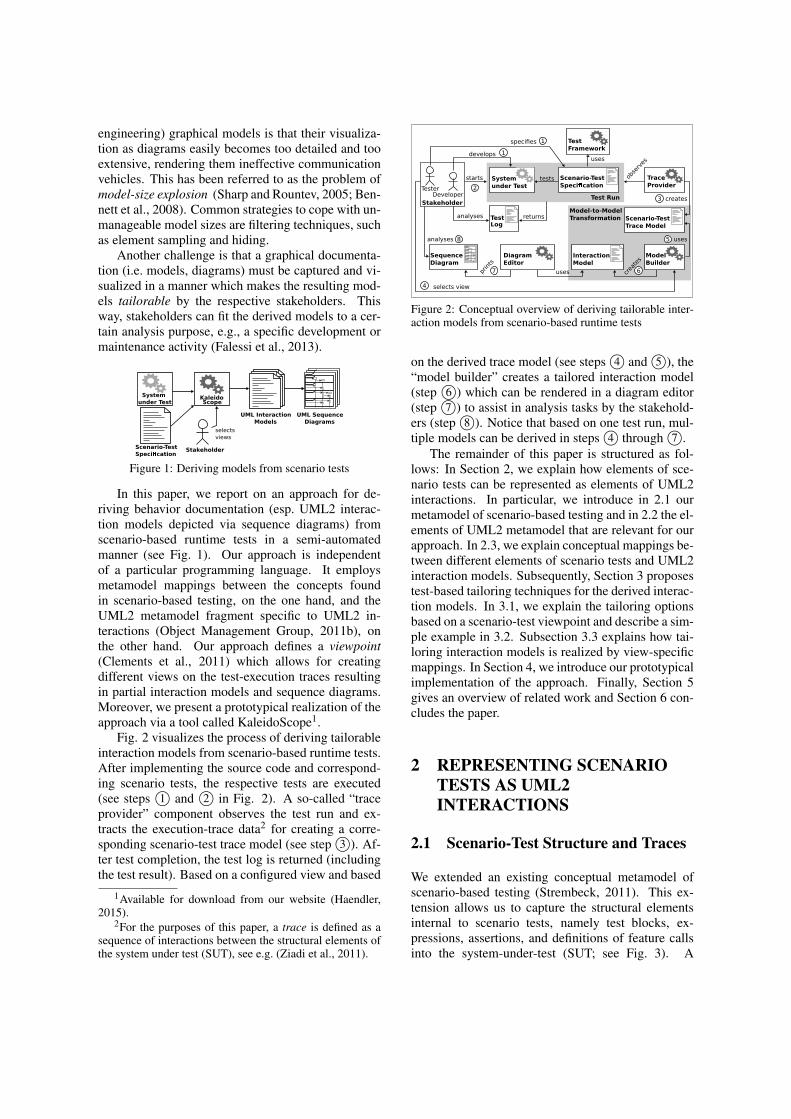
In this paper, we report on an approach for de-riving behavior documentation (esp. UML2 interac-tion models depicted via sequence diagrams) fromscenario-based runtime tests in a semi-automatedmanner (see Fig. 1). Our approach is independentof a particular programming language. It employsmetamodel mappings between the concepts foundin scenario-based testing, on the one hand, and theUML2 metamodel fragment specific to UML2 in-teractions (Object Management Group, 2011b), onthe other hand. Our approach defines a viewpoint(Clements et al., 2011) which allows for creatingdifferent views on the test-execution traces resultingin partial interaction models and sequence diagrams.Moreover, we present a prototypical realization of theapproach via a tool called KaleidoScope1.
Fig. 2 visualizes the process of deriving tailorableinteraction models from scenario-based runtime tests.After implementing the source code and correspond-ing scenario tests, the respective tests are executed(see steps 1© and 2© in Fig. 2). A so-called “traceprovider” component observes the test run and ex-tracts the execution-trace data2 for creating a corre-sponding scenario-test trace model (see step 3©). Af-ter test completion, the test log is returned (includingthe test result). Based on a configured view and based
1Available for download from our website (Haendler,2015).
2For the purposes of this paper, a trace is defined as asequence of interactions between the structural elements ofthe system under test (SUT), see e.g. (Ziadi et al., 2011).
developsuses
TesterDeveloper
Stakeholder
selects view
System
under Test
Test
Framework
Scenario-Test
Speci cation
Trace
Provider
Interaction
Model
Sequence
Diagram
setup
sd run2
precond.
postcond.
testbody
cleanup
Test Run
Model
Builder
Scenario-Test
Trace Model
Diagram
Editor
TestLog
tests obse
rves
creates
uses
uses crea
tes
prin
ts
analyses
analyses returns
1
starts
2
3
4
5
67
8
specifies
Model-to-Model
Transformation
1
Figure 2: Conceptual overview of deriving tailorable inter-action models from scenario-based runtime tests
on the derived trace model (see steps 4© and 5©), the“model builder” creates a tailored interaction model(step 6©) which can be rendered in a diagram editor(step 7©) to assist in analysis tasks by the stakehold-ers (step 8©). Notice that based on one test run, mul-tiple models can be derived in steps 4© through 7©.
The remainder of this paper is structured as fol-lows: In Section 2, we explain how elements of sce-nario tests can be represented as elements of UML2interactions. In particular, we introduce in 2.1 ourmetamodel of scenario-based testing and in 2.2 the el-ements of UML2 metamodel that are relevant for ourapproach. In 2.3, we explain conceptual mappings be-tween different elements of scenario tests and UML2interaction models. Subsequently, Section 3 proposestest-based tailoring techniques for the derived interac-tion models. In 3.1, we explain the tailoring optionsbased on a scenario-test viewpoint and describe a sim-ple example in 3.2. Subsection 3.3 explains how tai-loring interaction models is realized by view-specificmappings. In Section 4, we introduce our prototypicalimplementation of the approach. Finally, Section 5gives an overview of related work and Section 6 con-cludes the paper.
2 REPRESENTING SCENARIOTESTS AS UML2INTERACTIONS
2.1 Scenario-Test Structure and Traces
We extended an existing conceptual metamodel ofscenario-based testing (Strembeck, 2011). This ex-tension allows us to capture the structural elementsinternal to scenario tests, namely test blocks, ex-pressions, assertions, and definitions of feature callsinto the system-under-test (SUT; see Fig. 3). A
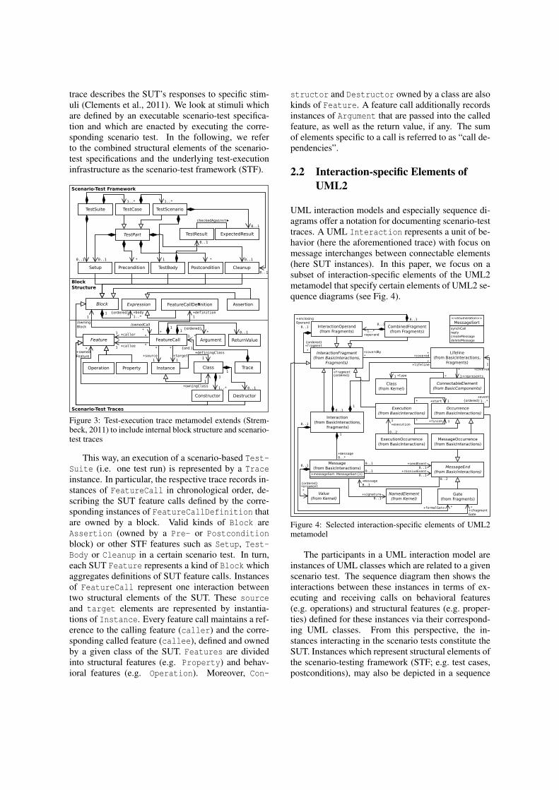
trace describes the SUT’s responses to specific stim-uli (Clements et al., 2011). We look at stimuli whichare defined by an executable scenario-test specifica-tion and which are enacted by executing the corre-sponding scenario test. In the following, we referto the combined structural elements of the scenario-test specifications and the underlying test-executioninfrastructure as the scenario-test framework (STF).
1
1..* 1..*
*
+definition
1
11
TestSuite TestCase TestScenario
TestPart TestResult ExpectedResult
Setup Precondition TestBody Postcondition Cleanup
Block AssertionExpression FeatureCallDe nition
+target
1
*+callee1 * *
1
1
+source
1
11
*+caller1
* *
Class
Feature FeatureCall
Instance
ReturnValueArgument
Trace
0..1
0..1
checkedAgainst
{ordered}
{ordered}
/owning
Block/ownedCall
0..1
*1..*
0..1
0..1 0..1
+body
1..*
*
Operation Property
Constructor Destructor
+owningClass
1
*+owned
Feature
0..1
+definingClass
1
{ord.}
0..11..*
Scenario-Test Framework
Scenario-Test Traces
Block
Structure
Figure 3: Test-execution trace metamodel extends (Strem-beck, 2011) to include internal block structure and scenario-test traces
This way, an execution of a scenario-based Test-Suite (i.e. one test run) is represented by a Traceinstance. In particular, the respective trace records in-stances of FeatureCall in chronological order, de-scribing the SUT feature calls defined by the corre-sponding instances of FeatureCallDefinition thatare owned by a block. Valid kinds of Block areAssertion (owned by a Pre- or Postconditionblock) or other STF features such as Setup, Test-Body or Cleanup in a certain scenario test. In turn,each SUT Feature represents a kind of Block whichaggregates definitions of SUT feature calls. Instancesof FeatureCall represent one interaction betweentwo structural elements of the SUT. These sourceand target elements are represented by instantia-tions of Instance. Every feature call maintains a ref-erence to the calling feature (caller) and the corre-sponding called feature (callee), defined and ownedby a given class of the SUT. Features are dividedinto structural features (e.g. Property) and behav-ioral features (e.g. Operation). Moreover, Con-
structor and Destructor owned by a class are alsokinds of Feature. A feature call additionally recordsinstances of Argument that are passed into the calledfeature, as well as the return value, if any. The sumof elements specific to a call is referred to as “call de-pendencies”.
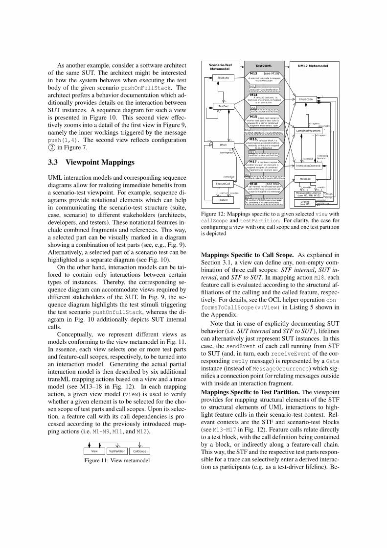
2.2 Interaction-specific Elements ofUML2
UML interaction models and especially sequence di-agrams offer a notation for documenting scenario-testtraces. A UML Interaction represents a unit of be-havior (here the aforementioned trace) with focus onmessage interchanges between connectable elements(here SUT instances). In this paper, we focus on asubset of interaction-specific elements of the UML2metamodel that specify certain elements of UML2 se-quence diagrams (see Fig. 4).
+message
0..*
1
0..1 +sendEvent
0..10..1 +receiveEvent
0..1
1
*+lifeline
0..1
+formalGate *
0..2+message
0..1
*
+represents1*+type1
*
+signature
0..1
+covered*+coverdBy
*
0..1
+fragment*
0..1
+operand1..*
Message
(from BasicInteractions)
+messageSort: MessageSort [1]
<<enumeration>>
MessageSort
synchCall
reply
createMessage
deleteMessage
0..1
+fragment
*
0..1
*+cfragment
Gate
+enclosing
Operand
{ordered}
{ordered}
{ordered}
{ordered}
+event
1..*
+covered
1
Value
(from Kernel)
Occurrence
(from BasicInteractions)
Lifeline
(from BasicInteractions,
Fragments)
Gate
(from Fragments)
NamedElement
(from Kernel)
MessageEnd
(from BasicInteractions)
MessageOccurrence
(from BasicInteractions)
InteractionFragment
(from BasicInteractions,
Fragments)
ConnectableElement
(from BasicComponents)Class
(from Kernel)
CombinedFragment
(from Fragments)
InteractionOperand
(from Fragments)
Interaction
(from BasicInteractions,
Fragments)
0..1
+argument
*
Execution
(from BasicInteractions)
ExecutionOccurrence
(from BasicInteractions)
+start 1*
+finish 1*
0..2
1
+execution
Figure 4: Selected interaction-specific elements of UML2metamodel
The participants in a UML interaction model areinstances of UML classes which are related to a givenscenario test. The sequence diagram then shows theinteractions between these instances in terms of ex-ecuting and receiving calls on behavioral features(e.g. operations) and structural features (e.g. proper-ties) defined for these instances via their correspond-ing UML classes. From this perspective, the in-stances interacting in the scenario tests constitute theSUT. Instances which represent structural elements ofthe scenario-testing framework (STF; e.g. test cases,postconditions), may also be depicted in a sequence

diagram; for example as a test-driver lifeline (Cor-nelissen et al., 2007). The feature calls on SUT in-stances originating from STF instances rather thanother SUT instances represent the aforementionedstimuli. This way, such feature calls designate the be-ginning and the end of a scenario-test trace.
2.3 Mapping Test Traces to Interactions
To transform scenario-test traces into UML inter-actions, we define a metamodel mapping based onthe scenario-test trace metamodel, on the one hand,and the corresponding excerpt from the UML2 meta-model, on the other hand.
For the purposes of this paper, we formalizedthe corresponding mappings using transML dia-grams (Guerra et al., 2013). transML diagrams repre-sent model transformations in a tool- and technology-independent manner compatible with the UML. In to-tal, 18 mapping actions are used to express the cor-respondences. These mapping actions (M1–M18) arevisualized in Figures 5, 6 and 12.
The transML mapping diagrams are amendedby OCL expressions (Object Management Group,2014b) to capture important mapping and consistencyconstraints for the resulting UML interaction models.The mapping constraints are depicted below each re-lated transML mapping action, which represents thecontext for the OCL constraints and, this way, allowsfor navigating to elements of the input and outputmodel. To improve diagram readability, the constraintexpressions are omitted in the mapping diagrams pre-sented in this paper.3
In general, i.e. independent of a particular view,each Trace instance, which comprises one or severalfeature calls, is mapped to an instance of UML In-teraction (see M10 in Fig. 5). This way, the result-ing interaction model reflects the entire test-executiontrace (for viewpoint mappings, see Subsection 3.3).However, each instance of FeatureCall (fC) con-tained by a given trace is mapped to at least one UMLMessage instance (see M4). Each of the mappings ofthe other trace elements (i.e. “call dependencies”) de-pends on mapping M4 and is specific to fC.
Each instance that serves as source or tar-get of a feature call is captured in terms of a pairof a ConnectableElement instance and a Life-line instance. A Lifeline, therefore, representsa participant in the traced interaction, i.e., a Con-nectableElement typed with the UML class of theparticipant. See the transML mapping actions M1 andM2 in Fig. 5.
3However, the OCL constraints are fully reported in theAppendix of this paper.
1
OCL
instance=fC.source or
instance=fC.target
Scenario-Test
MetamodelUML2 Metamodel Test2UML
Argument
FeatureCall
Feature
Instance
Class
Value
Message
MessageOccurrence
ConnectableElement
Lifeline
Class
+argument
+receiveEv.
1
+event*
+cov.1
+repr.
1
+type
1
+callee1
+target1
1
1 1
1
* *
+owningClass
1
*
+owned
Feature
NamedElement
Execution
MessageSort
+start
sendEv.
receiveEv.
synchCall
deleteM.
createM.
+source
1
*
*
*
+caller1
+sendEv.
1
1
+signature
1
Trace Interaction
*
fragment*
*
*
*
+fragment*
Constructor
Destructor
*
+covered1
M1
M2
M4
M5
M6
M7
M8
A de nition of source or target
instance is mapped to a class
A source or target instance is
mapped to a connectable element
represented by a lifeline
A feature call (fC) is mapped
to a message
A calling feature is mapped to
a message occurrence as
send event
A called feature is mapped to
a message occurrence as
receive event
A called feature that
is neither constructor nor destructor
is mapped to execution,
signature and message sort
A called constructor is mapped
to signature and message sort
M9
M10
A called destructor is mapped
to signature and message sort
A trace is mapped to an
interaction
M3
An argument is mapped to a value
1
OCL
class=fC.source.de nition or
class=fC.target.de nition
OCL
argument=fC.argument
OCL
feature=fC.caller
OCLfeature=fC.callee and not
(feature.oclIsTypeOf(Constructor)
or feature.oclIsTypeOf(Destructor))
OCL
constructor=fC.callee
OCL
feature=fC.callee
OCL
destructor=fC.callee
+de ning
Class
*
Figure 5: Mapping elements of scenario-test traces specificto a feature call (fC)
An instance of MessageOccurrence in the result-ing interaction model represents the feature call atthe calling feature’s end as a sendEvent (see M5).Likewise, at the called feature’s end, the feature callmaps to a receiveEvent (see M6). Depending onthe kind of the feature call, the resulting Message in-stance is annotated differently. For constructor anddestructor calls, the related message has a «create»or «delete» signature, respectively. In addition,the corresponding message is marked using mes-sageSort createMessage or deleteMessage, re-spectively (see M8 and M9). Note that in case of a con-structor call, the target is represented by the class ofthe created instance and the created instance is the re-turn value. This way, here, the return value is mappedto lifeline and connectable element typed by the tar-get (see M8).
Other calls map to synchronous messages (i.e.messageSort synchCall). In this case, the name ofthe callee feature and the names of the argumentspassed into the call are mapped to the signature ofthe corresponding Message instance (see M7). In addi-tion, an execution is created in the interaction model.

An Execution represents the enactment of a unit ofbehavior within the lifeline (here the execution of acalled feature). The resulting Execution instance be-longs to the lifeline of the target instance and itsstart is marked by the message occurrence createdby applying M6. For the corresponding OCL consis-tency constraints based on mapping M4, see Listing 3in the Appendix.
0..1
FeatureCall
ReturnValue
Message
MessageOccurrence
ExecutionOccurrence
Execution(see M7)
NamedElement
MessageSort
+finish
0..1
+signature
+receiveEv.
receiveEv.
+sendEv.sendEv.
Instance Lifeline
+covered1
+covered
1+source
1+target1
OCL
fC.returnValue->isEmpty()
OCL
returnValue=fC.returnValue
Trace Interaction
**
*
*
+fragment*
+fragment*
1
1 1
1
1
+frgm.
*
+finish 0..1
finish
+covered1
see M2
see M10
M11
M12
A feature call is mapped to
execution occurrence if no
return value exists
A return value is mapped to
message, to signature and
message sort and to message
occurrences as send and
receive event
reply
Test2UMLScenario-Test
MetamodelUML2 Metamodel
1
Figure 6: Mapping return value specific to a feature call(fC)
If a given feature call fC reports a return value,a second Message instance will be created to rep-resent this return value. This second message ismarked as having messageSort reply (see M12 inFig. 6). Moreover, two instances of MessageOccur-rence are created acting as the sendEvent and thereceiveEvent (covering the lifelines mapped fromtarget and source instance related to fC, respec-tively). An instance of NamedElement acts as thesignature of this message, reflecting the actual re-turn value (see M12). In case of a missing return value,an ExecutionOccurrence instance is provided toconsume the call execution (finish) at the called fea-ture’s end (see M11). Listing 4 in the Appendix pro-vides the corresponding OCL consistency constraintsbased on mapping M12.
The chronological order of the FeatureCall in-stances in the recorded trace must be preserved inthe interaction model. Therefore we require thatthe message occurrences serving as send and re-ceiveEvents of the derived messages (see M5, M6,M12) preserve this order on the respective lifelines(along with the execution occurrences). This means,that after receiving a message (receiveEvent), thesend events derived from called nested features areadded in form of events covering the lifeline. In caseof synchronous calls with owned return values, for
each message, the receive event related to the replymessage enters the set of ordered events (see M12) be-fore adding the send event of the next call.
3 VIEWS ON TEST-EXECUTIONTRACES
In this section, we discuss how the mappings fromSection 2 can be extended to render the derived in-teraction models tailorable. By tailoring, we refer tospecific means for zooming in and out on selecteddetails of an interaction model; and for pruning se-lected details. For this purpose, our approach definesa scenario-test viewpoint.
A viewpoint (Clements et al., 2011) stipulates theelement types (e.g. scenario-test parts, feature-callscopes) and the types of relationships between theseelement types (e.g. selected, unselected) available fordefining different views on test-execution traces. Onthe one hand, applying the viewpoint allows for con-trolling model-size explosion. On the other hand, theviews offered on the derived models can help tailorthe corresponding behavior documentation for giventasks (e.g. test or code reviews) and/or stakeholderroles (e.g. test developer, software architect).
t. suite sp. test case
setu
p
cle
anu
p
setu
p
pre
cond.
postc
ond.
cle
anu
p
stackTest pushElement
sp. test scenario
test
body
setu
p
pre
cond.
postc
ond.
cle
anu
p
pushOnFullStack
STF to SUT
SUT intern.
STF intern.
test parts
callscopes
1
2
contains
one or many
contains
one or many
multiple
test runs
Figure 7: Example of option space for defining views ontest-execution traces, by combining scenario-test parts andfeature-call scopes
3.1 Scenario-Test Viewpoint
To tailor the derived interaction models, two char-acteristics of scenario tests and the correspondingscenario-test traces can be leveraged: the whole-partstructure of scenario tests and trackable feature-callscopes.Scenario-test Parts. Scenario tests, in terms of con-cepts and their specification structure, are composedof different parts (see Section 2.1 and Fig. 3):
• A test suite encompasses one or more test cases.• A test case comprises one or more test scenarios.

• A test case, and a test scenario can contain asser-tion blocks to specify pre- and post-conditions.
• A test suite, a test case, and a test scenario cancontain exercise blocks, as setup, or cleanup pro-cedures.
• A test scenario contains a test body.Feature-call Scopes. Each feature call in a scenario-test trace is scoped according to the scenario-testframework (STF) and the system under test (SUT),respectively, as the source and the target of the fea-ture call. This way, we can differentiate between threefeature-call scopes:
• feature calls running from the STF to the SUT (i.e.test stimuli),
• feature calls internal to the SUT (triggered by teststimuli directly and indirectly),
• feature calls internal to the STF.The scenario-test parts and feature-call scopes
form a large option space for tailoring an interactionmodel. In Figure 7, these tailoring options are visu-alized as a configuration matrix. For instance, a testsuite containing one test case with just one includedtest scenario offers 14,329 different interaction-modelviews available for configuration based on one test run(provided that the corresponding test blocks are spec-ified).4
In the subsequent section, we demonstrate by ex-ample the relevance of specifying different views onthe test-execution traces for different tasks and/orstakeholder roles.
Stack
-limit: Integer [1]
-element: Double [*]
+push(e:Double): Boolean
+pop(): Double
+size(): Integer
+full(): Boolean
-getElements(): Double[]
+getLimit(): Integer
+setLimit(l:Integer)
Figure 8: UMLclass diagram ofexemplary SUT
Listing 1: Natural-language no-tation of scenario pushOnFull-Stack
1 Given: 'that a specific instanceof Stack contains elementsof the size of 2 and has alimit of 2'
2 When: 'an element is pushed onthe instance of Stack'
3 Then: 'the push operation failsand the size of elements isstill 2'
3.2 Example
Consider the example of a test developer whose pri-mary task is to conduct a test-code review. For thisreview, she is responsible for verifying a test-scenario
4The number of views computes as follows: There are(23 − 1) non-empty combinations of the three feature-callscopes (SUT internal, STF internal, STF to SUT) times the(211 −1) non-empty combinations of at least 11 individualtest parts (e.g. setup of test case, test body of test scenario).
script against a scenario-based requirements descrip-tion. The scenario is named pushOnFullStack andspecified in Listing 1. The test script to be reviewedis shown in Listing 2.
Listing 2: Test scenario pushOnFullStack.1 # It is provided in the setup script of the owning test
case pushElement that an instance of Stack existscontaining the two elements 3.5 and 4.3
2 set fs [::STORM::TestScenario new -name pushOnFullStack-testcase pushElement]
3 $fs expected_result set 04 $fs setup_script set {5 [::Stack info instances] limit set 26 }7 $fs preconditions set {8 {expr {[[::Stack info instances] size] == 2}}9 {expr {[[::Stack info instances] limit get] == 2}}10 }11 $fs test_body set {12 [::Stack info instances] push 1.413 }14 $fs postconditions set {15 {expr {[[::Stack info instances] size] == 2}}16 }
The small system under test (SUT), a stack-based dis-penser component, is visualized in Fig. 8 as a UMLclass diagram. A Stack provides the operations push,pop, size, and full as well as the attributes limitand element. Attributes are accessible via corre-sponding getter/setter operations (i.e. getElements,getLimit and setLimit).
:Stack
sd pushOnFullStack
size()
getLimit()
size()
2
2
2
setLimit(2)
test
:TestDriver
setup
scenario
preconditions
push(1.4)
false
postcond.
test body
Figure 9: Sequence diagramderived from pushOnFull-Stack highlighting callsrunning from STF to SUT
push(1.4)
false
full()
getLimit()
2
size()
true
:Stack
getElements()
[3.5, 4.3]
2
test body
sd pushOnFullStack
:TestDriver
Figure 10: Sequence dia-gram derived from pushOn-FullStack zooming in ontest body and representingboth, calls running fromSTF to SUT and calls inter-nal to the SUT
To support her in this task, our approach can pro-vide her with a partial UML sequence diagram whichdepicts only selected details of the test-executiontrace. These details of interest could be interactionstriggered by specific blocks of the test under review,for example. Such a view provides immediate ben-efits to the test developer. The exemplary view inFigure 9 gives details on the interactions between theSTF and the SUT, i.e. the test stimuli observed underthis specific scenario. To obtain this view, the con-figuration pulls feature calls from a combination ofsetup, precondition, test body and postcondition spe-cific to this test scenario. The view from Figure 9corresponds to configuration 1© in Figure 7.
As another example, consider a software architectof the same SUT. The architect might be interestedin how the system behaves when executing the testbody of the given scenario pushOnFullStack. Thearchitect prefers a behavior documentation which ad-ditionally provides details on the interaction betweenSUT instances. A sequence diagram for such a viewis presented in Figure 10. This second view effec-tively zooms into a detail of the first view in Figure 9,namely the inner workings triggered by the messagepush(1,4). The second view reflects configuration2© in Figure 7.
3.3 Viewpoint Mappings
UML interaction models and corresponding sequencediagrams allow for realizing immediate benefits froma scenario-test viewpoint. For example, sequence di-agrams provide notational elements which can helpin communicating the scenario-test structure (suite,case, scenario) to different stakeholders (architects,developers, and testers). These notational features in-clude combined fragments and references. This way,a selected part can be visually marked in a diagramshowing a combination of test parts (see, e.g., Fig. 9).Alternatively, a selected part of a scenario test can behighlighted as a separate diagram (see Fig. 10).
On the other hand, interaction models can be tai-lored to contain only interactions between certaintypes of instances. Thereby, the corresponding se-quence diagram can accommodate views required bydifferent stakeholders of the SUT. In Fig. 9, the se-quence diagram highlights the test stimuli triggeringthe test scenario pushOnfullStack, whereas the di-agram in Fig. 10 additionally depicts SUT internalcalls.
Conceptually, we represent different views asmodels conforming to the view metamodel in Fig. 11.In essence, each view selects one or more test partsand feature-call scopes, respectively, to be turned intoan interaction model. Generating the actual partialinteraction model is then described by six additionaltransML mapping actions based on a view and a tracemodel (see M13–18 in Fig. 12). In each mappingaction, a given view model (view) is used to verifywhether a given element is to be selected for the cho-sen scope of test parts and call scopes. Upon its selec-tion, a feature call with its call dependencies is pro-cessed according to the previously introduced map-ping actions (i.e. M1-M9, M11, and M12).
View TestPartition CallScope
* *
Figure 11: View metamodel
Scenario-Test
MetamodelUML2 Metamodel Test2UML
TestSuite
TestPart
Interaction
CombinedFragment
InteractionOperand
*
+fragment
*
+operand
1 0..1
+fragment*
+enclosing
Operand
/owningBlock
/ownedCall
*
* *
Block
Message
Feature
+callee
1
Lifeline(see M2)
MessageOccurrence
+coveredBy
*
+covered
*
+fragm.*+caller
1
+sendEv.
0..1
+recEv.
0..1
FeatureCall
+fragm.*
1
+lifeline
*
*
*
1
*
M13
M14
A selected test suite is mapped
to an interaction
(see M10)
M15
M16
M17
M18
A selected test part, i.e.
test case or scenario, is mapped
to an interaction
A selected block, i.e.
setup/cleanup, pre/postcondition,
testbody or feature is mapped
to an interaction
A call related to selected test part
and conforming to selected call
scope is mapped to a message
*
A test part nested in
another test part or test suite is
mapped to a pair of combined
fragment and interact. oper.
A test block nested in
another test part or test suite is
mapped to a pair of combined
fragment and interact. oper.
(see M4)
(see M5, M6, M12)
OCL
testSuite=view.testPartition
OCL
testPart=view.testPartition
OCL
testBlock=view.testPartition
OCLfC.conformsToCallScope(view) and
fC.conformsToTestPartition(view)
OCL
testPart.isNestedIn(view.testPartition)
OCL
testBlock.isNestedIn(view.testPartition)
Figure 12: Mappings specific to a given selected view withcallScope and testPartition. For clarity, the case forconfiguring a view with one call scope and one test partitionis depicted
Mappings Specific to Call Scope. As explained inSection 3.1, a view can define any, non-empty com-bination of three call scopes: STF internal, SUT in-ternal, and STF to SUT. In mapping action M18, eachfeature call is evaluated according to the structural af-filiations of the calling and the called feature, respec-tively. For details, see the OCL helper operation con-formsToCallScope(v:View) in Listing 5 shown inthe Appendix.
Note that in case of explicitly documenting SUTbehavior (i.e. SUT internal and STF to SUT), lifelinescan alternatively just represent SUT instances. In thiscase, the sendEvent of each call running from STFto SUT (and, in turn, each receiveEvent of the cor-responding reply message) is represented by a Gateinstance (instead of MessageOccurrence) which sig-nifies a connection point for relating messages outsidewith inside an interaction fragment.Mappings Specific to Test Partition. The viewpointprovides for mapping structural elements of the STFto structural elements of UML interactions to high-light feature calls in their scenario-test context. Rel-evant contexts are the STF and scenario-test blocks(see M13-M17 in Fig. 12). Feature calls relate directlyto a test block, with the call definition being containedby a block, or indirectly along a feature-call chain.This way, the STF and the respective test parts respon-sible for a trace can selectively enter a derived interac-tion as participants (e.g. as a test-driver lifeline). Be-
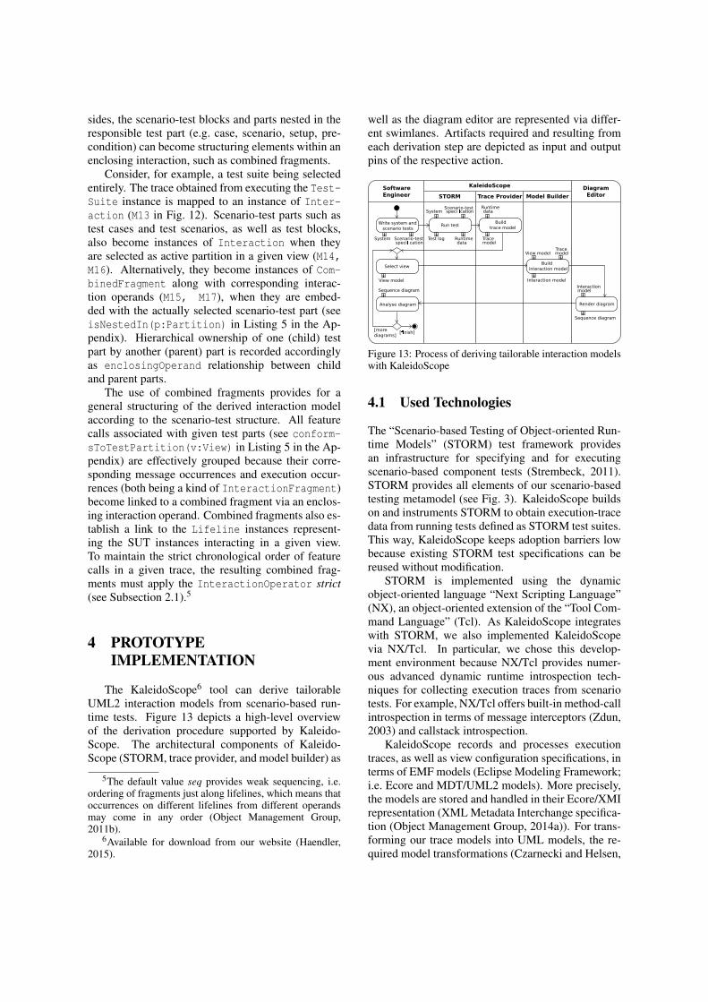
sides, the scenario-test blocks and parts nested in theresponsible test part (e.g. case, scenario, setup, pre-condition) can become structuring elements within anenclosing interaction, such as combined fragments.
Consider, for example, a test suite being selectedentirely. The trace obtained from executing the Test-Suite instance is mapped to an instance of Inter-action (M13 in Fig. 12). Scenario-test parts such astest cases and test scenarios, as well as test blocks,also become instances of Interaction when theyare selected as active partition in a given view (M14,M16). Alternatively, they become instances of Com-binedFragment along with corresponding interac-tion operands (M15, M17), when they are embed-ded with the actually selected scenario-test part (seeisNestedIn(p:Partition) in Listing 5 in the Ap-pendix). Hierarchical ownership of one (child) testpart by another (parent) part is recorded accordinglyas enclosingOperand relationship between childand parent parts.
The use of combined fragments provides for ageneral structuring of the derived interaction modelaccording to the scenario-test structure. All featurecalls associated with given test parts (see conform-sToTestPartition(v:View) in Listing 5 in the Ap-pendix) are effectively grouped because their corre-sponding message occurrences and execution occur-rences (both being a kind of InteractionFragment)become linked to a combined fragment via an enclos-ing interaction operand. Combined fragments also es-tablish a link to the Lifeline instances represent-ing the SUT instances interacting in a given view.To maintain the strict chronological order of featurecalls in a given trace, the resulting combined frag-ments must apply the InteractionOperator strict(see Subsection 2.1).5
4 PROTOTYPEIMPLEMENTATION
The KaleidoScope6 tool can derive tailorableUML2 interaction models from scenario-based run-time tests. Figure 13 depicts a high-level overviewof the derivation procedure supported by Kaleido-Scope. The architectural components of Kaleido-Scope (STORM, trace provider, and model builder) as
5The default value seq provides weak sequencing, i.e.ordering of fragments just along lifelines, which means thatoccurrences on different lifelines from different operandsmay come in any order (Object Management Group,2011b).
6Available for download from our website (Haendler,2015).
well as the diagram editor are represented via differ-ent swimlanes. Artifacts required and resulting fromeach derivation step are depicted as input and outputpins of the respective action.
Interaction model
System
Sequence diagram
Select view
Scenario-test
Scenario-testspeci cationSystem
Test log Runtime
Sequence diagram
Software
Engineer
KaleidoScope
Run test
Render diagram
Write system and
scenario tests
Build
interaction model
Analyse diagram
[more
diagrams] [ nish]
Build
trace model
STORM Trace Provider Model Builder
Diagram
Editor
data
Runtime data
Trace model
Interaction
speci cation
View modelTrace model
model
View model
Figure 13: Process of deriving tailorable interaction modelswith KaleidoScope
4.1 Used Technologies
The “Scenario-based Testing of Object-oriented Run-time Models” (STORM) test framework providesan infrastructure for specifying and for executingscenario-based component tests (Strembeck, 2011).STORM provides all elements of our scenario-basedtesting metamodel (see Fig. 3). KaleidoScope buildson and instruments STORM to obtain execution-tracedata from running tests defined as STORM test suites.This way, KaleidoScope keeps adoption barriers lowbecause existing STORM test specifications can bereused without modification.
STORM is implemented using the dynamicobject-oriented language “Next Scripting Language”(NX), an object-oriented extension of the “Tool Com-mand Language” (Tcl). As KaleidoScope integrateswith STORM, we also implemented KaleidoScopevia NX/Tcl. In particular, we chose this develop-ment environment because NX/Tcl provides numer-ous advanced dynamic runtime introspection tech-niques for collecting execution traces from scenariotests. For example, NX/Tcl offers built-in method-callintrospection in terms of message interceptors (Zdun,2003) and callstack introspection.
KaleidoScope records and processes executiontraces, as well as view configuration specifications, interms of EMF models (Eclipse Modeling Framework;i.e. Ecore and MDT/UML2 models). More precisely,the models are stored and handled in their Ecore/XMIrepresentation (XML Metadata Interchange specifica-tion (Object Management Group, 2014a)). For trans-forming our trace models into UML models, the re-quired model transformations (Czarnecki and Helsen,

2003) are implemented via “Query View Transforma-tions Operational” (QVTo) mappings (Object Man-agement Group, 2011a). QVTo allows for implement-ing concrete model transformations based on concep-tual transformation in a straightforward manner.
4.2 Derivation Actions
Run Scenario Tests. For deriving interaction mod-els via KaleidoScope, a newly created or an existingscenario-test suite is executed by the STORM engine.At this point, and from the perspective of the soft-ware engineer, this derivation-enabled test executiondoes not deviate from an ordinary one. The primaryobjective of this test run is to obtain the runtime datarequired to build a trace model. Relevant runtime dataconsist of scenario-test traces (SUT feature calls andtheir call dependencies), on the one hand, and struc-tural elements of the scenario-test specifications (asubset of STF feature calls and their call dependen-cies), on the other hand.Build Trace Models. Internally, the trace-providercomponent of KaleidoScope instruments the STORMengine before the actual test execution to record thecorresponding runtime data. This involves intercept-ing each call of relevant features and deriving the cor-responding call dependencies. At the same time, thetrace provider ascertains that its instrumentation re-mains transparent to the STORM engine.
To achieve this, the trace provider instruments theSTORM engine and the tests under execution usingNX/Tcl introspection techniques. In NX/Tcl, method-call introspection is supported via two variants ofmessage interceptors (Zdun, 2003): mixins and fil-ters. Mixins (Zdun et al., 2007) can be used to dec-orate entire components and objects. Thereby, theyintercept calls to methods which are known a priori.In KaleidoScope, the trace provider registers a mixinto intercept relevant feature calls on the STF, i.e. theSTORM engine. Filters (Neumann and Zdun, 1999)are used by the trace provider to intercept calls to ob-jects of the SUT which are not known beforehand.
To record relevant feature-call dependencies, thetrace provider uses the callstack introspection of-fered by NX/Tcl. NX/Tcl offers access to its op-eration callstack via special-purpose introspectioncommands, e.g. nx::current, see (Neumann andSobernig, 2015). To collect structural data on the in-tercepted STF and SUT instances, the trace providerpiggybacks onto the structural introspection facilityof NX/Tcl, e.g., info methods, see (Neumann andSobernig, 2015). This way, structural data such asclass names, feature names, and relationships be-tween classes can be requested.
The collected runtime data is then processed bythe trace provider. In particular, feature calls at theapplication level are filtered to include only calls forthe scope of the SUT. This way, calls into other sys-tem contexts (e.g., external components or lower-levelhost language calls) are discarded. In addition, theexecution traces are reordered to report “invocationsinteractions” first and “return interactions” second.Moreover, the recorded SUT calls are linked to therespective owning test blocks.
The processed runtime data is then stored as atrace model which conforms to the Trace metamodeldefined via Ecore (see Fig. 14). This resulting tracemodel comprises the relevant structural elements (testsuite, test case and test scenario), the SUT featurecalls and their call dependencies, each being linkedto a corresponding test block.
TraceModel
name : EString
FeatureCall
name : EString
de�nedBySTF : EBoolean
Feature
name : EString
isConstructor : EBoolean
isDestructor : EBoolean
Instance
name : EString
Class
name : EString
Argument
name : EString
ReturnValue
name : EString
<<enumeration>>
TestBlockKind
setup
checkPreConditions
test
checkPostConditions
cleanup
TestScenario
name : EString
TestCase
name : EString
TestBlock
name : TestBlockKind
TestSuite
name : EString
Trace
name : EString
feature
0..*class
0..*
instance
0..*
testSuite1
trace 1
argument 0..*
returnValue0..1
source1
target1
caller1callee1owningClass1
de�nition1
ownedFeature0..*
block
1..*
scenario
1..*
block0..*
call 0..*
case
1..*
block
0..*
call
0..*
Figure 14: Trace metamodel, EMF Ecore
Select Views. Based on the specifics of the test run(e.g. whether an entire test suite or selected test caseswere executed) and the kind of runtime data collected,different views are available to the software engineerfor selection. In KaleidoScope, the software engi-neer can select a particular view by defining a viewmodel. This view model must conform to the Viewmetamodel specified using Ecore (see Fig. 15). Kalei-doScope allows for defining views on the behavior ofthe SUT by combining a selected call scope (SUT in-ternal, STF to SUT, or both) and a selected test parti-tion (entire test suite or a specific test case, scenario,or block), as described in Section 3.
View
callScope : CallScopeKind
name : EString
TestPartition
testBlock : TestBlockKind
testScenario : EString
testCase : EString
isEntireTestSuite : EBoolean
name : EString
<<enumeration>>
CallScopeKind
stfToSut
sutIntern
<<enumeration>>
TestBlockKind
setup
preconditions
testbody
postconditions
cleanup
partition1
both
Figure 15: View metamodel, EMF Ecore
Build Interaction Models. The model-builder com-ponent of KaleidoScope takes the previously createdpair of a trace model and a view model as input mod-els for a collection of QVTo model transformations.The output model of these QVTo transformations is

the UML interaction model. The conceptual map-pings presented in Subsections 2.3 and 3.3 are imple-mented in QVT Operational mappings (Object Man-agement Group, 2011a), including the linking of rela-tionships between the derived elements. In total, thetransformation file contains 24 mapping actions.Display Sequence Diagrams. Displaying the derivedinteraction models as sequence diagrams and present-ing them to the software engineer is not handled byKaleidoScope itself. As the derived interaction mod-els are available in the XMI representation, they canbe imported by XMI-compliant diagram editors. Inour daily practice, we use Eclipse Papyrus (EclipseFoundation, 2015) for this task.
5 RELATED WORK
Closely related research can be roughly dividedinto three groups: reverse-engineering sequence di-agrams from system execution, techniques address-ing the problem of model-size explosion in reverse-engineered behavioral models and extracting trace-ability links between test and system artifacts.Reverse-engineering UML Sequence Diagrams.Approaches applying dynamic analysis set thebroader context of our work (Oechsle and Schmitt,2002; Briand et al., 2003; Guéhéneuc and Ziadi,2005; Delamare et al., 2006). Of particular inter-est are model-driven approaches which provide con-ceptual mappings between runtime-data models andUML interaction models.
Briand et al. (2003) as well as Cornelissen etal. (2007) are exemplary for such model-driven ap-proaches. In their approaches, UML sequence dia-grams are derived from executing runtime tests. Bothdescribe metamodels to define sequence diagrams andfor capturing system execution in form of a tracemodel. Briand et al. define mappings between thesetwo metamodels in terms of OCL consistency con-straints. Each test execution relates to a single use-case scenario defined by a system-level test case.Their approaches differ from ours in some respects.The authors build on generic trace metamodels whilewe extend an existing scenario-test metamodel tocover test-execution traces. Briand et al. do not pro-vide for scoping the derived sequence diagrams basedon the executed tests unlike Cornelissen et al. (see be-low). They, finally, do not capture the mappings be-tween trace and sequence model in a formalized way.Countering Model-size Explosion. A second groupof related approaches aims at addressing the prob-lem of size explosion in reverse-engineered behav-ioral models. Fernández-Sáez et al. (2015) conducted
a controlled experiment on the perceived effects of de-rived UML sequence diagrams on maintaining a soft-ware system. A key result is that derived sequence di-agrams do not necessarily facilitate maintenance tasksdue to an excessive level of detail. Hamou-Lhadjand Lethbridge (2004) and Bennett et al. (2008) sur-veyed available techniques which can act as countermeasures against model-size explosion. The availabletechniques fall into three categories: slicing and prun-ing of components and calls as well as architecture-level filtering.
Slicing (or sampling) is a way of reducing the re-sulting model size by choosing a sample of execu-tion traces. Sharp and Rountev (2005) propose in-teractive slicing for zooming in on selected messagesand message chains. Grati et al. (2010) contributetechniques for interactively highlighting selected ex-ecution traces and for navigating through single ex-ecution steps. Pruning (or hiding) provides abstrac-tion by removing irrelevant details. For instance, Loand Maoz (2008) elaborate on filtering calls basedon different execution levels. In doing so, they pro-vide hiding of calls based on the distinction betweentriggers and effects of scenario executions. As anearly approach of architectural-level filtering, Rich-ner and Ducasse (1999) provide for tailorable viewson object-oriented systems, e.g., by filtering calls be-tween selected classes. In our approach, we adoptthese techniques for realizing different views con-forming to a scenario-test viewpoint. In particular,slicing corresponds to including interactions of cer-tain test parts (e.g., test cases, test scenarios) only,selectively hiding model elements to pulling fromdifferent feature-call scopes (e.g., stimuli and inter-nal calls). Architectural-level filtering is applied bydistinguishing elements by their structural affiliation(e.g., SUT or STF).
Test-to-system Traceability. Another importantgroup of related work provides for creating traceabil-ity links between test artifacts and system artifacts byprocessing test-execution traces. Parizi et al. (2014)give a systematic overview of such traceability tech-niques. For instance, test cases are associated withSUT elements based on the underlying call-trace datafor calculating metrics which reflect how each methodis tested (Kanstrén, 2008). Qusef et al. (2014) providetraceability links between unit tests and classes undertest. These links are extracted from trace slices gen-erated by assertion statements contained by the unittests. In general, these approaches do not necessar-ily derive behavioral diagrams, however Parizi et al.conclude by stating the need for visualizing traceabil-ity links. These approaches relate to ours by inves-tigating which SUT elements are covered by a spe-
cific part of the test specification. While they usethis information, e.g., for calculating coverage met-rics, we aim at visualizing the interactions for doc-umenting system behavior. However, Cornelissen etal. (2007) pursue a similar goal by visualizing theexecution of unit tests. By leveraging the structureof tests, they aim at improving the understandabilityof reverse-engineered sequence diagrams (see above),e.g., by representing the behavior of a particular stagein a separate sequence diagram. While they share ourmotivation for test-based partitioning, Cornelissen etal. do not present a conceptual or a concrete solutionto this partitioning. Moreover, we leverage the teststructure for organizing the sequence diagram (e.g.,by using combined fragments) and consider differentscopes of feature calls.
6 CONCLUSION
In this paper, we present an approach for derivingtailorable UML interaction models for documentingsystem behavior from scenario-based runtime tests.Our approach allows for leveraging the structure ofscenario tests (i.e. test parts and call scope) to tai-lor the derived interaction models, e.g., by pruningdetails and by zooming in and out on selected de-tails. This way, we also provide means to controlthe size explosion in the resulting UML sequence dia-grams. Our approach is model-driven in the sense thatexecution traces are represented through a dedicatedmetamodel, mappings between this metamodel andthe UML metamodel are captured as inter-model con-straint expressions (OCL), and model-to-model trans-formations are used to turn model representations ofexecution traces into UML interactions.
To demonstrate the feasibility of our approach,we developed a prototype implementation (Kaleido-Scope). Note, however, that our approach is applica-ble for any software system having an object-orienteddesign and implementation, provided that test suitestriggering inter-component interactions and a corre-sponding test framework, which can be instrumented,are available. In addition, the approach produces in-teraction models conforming to the de facto standardUML2.
In a next step, from a conceptual point of view,we will incorporate complementary structural modeltypes, namely class models. This is particularly chal-lenging as it requires abstraction techniques to extractscenario-based views from the observed system struc-ture. Besides, a prerequisite is the ability to com-bine dynamic runtime introspection and static pro-gram analysis. Moreover, this extension will require
additions to the scenario-test metamodel to model thestructure of the system under test.
From a practical angle, we will seek to apply theapproach on large-scale software projects. To com-plete this step, our prototype tooling will have to beextended to support runtime and program introspec-tion for other object-oriented programming languagesand for the corresponding testing frameworks. More-over, we plan to apply layout algorithms for automat-ically rendering the derived interaction models as se-quence diagrams.
REFERENCES
Bennett, C., Myers, D., Storey, M.-A., German,D. M., Ouellet, D., Salois, M., and Charland, P.(2008). A survey and evaluation of tool featuresfor understanding reverse-engineered sequencediagrams. Softw. Maint. Evol., 20(4):291–315.
Briand, L. C., Labiche, Y., and Miao, Y. (2003). To-wards the reverse engineering of UML sequencediagrams. In Proc. WCRE’03, pages 57–66.IEEE.
Carroll, J. M. (2000). Five reasons for scenario-baseddesign. Interact. Comput., 13(1):43–60.
Clements, P., Bachmann, F., Bass, L., Garlan, D.,Ivers, J., Little, R., Merson, P., Nord, R., andStafford, J. (2011). Documenting Software Ar-chitecture: Views and Beyond. SEI. Addison-Wesley, 2nd edition.
Cornelissen, B., Van Deursen, A., Moonen, L., andZaidman, A. (2007). Visualizing testsuites to aidin software understanding. In Proc. CSMR’07,pages 213–222. IEEE.
Czarnecki, K. and Helsen, S. (2003). Classification ofmodel transformation approaches. In WS Proc.OOPSLA’03, pages 1–17. ACM Press.
Delamare, R., Baudry, B., Le Traon, Y., et al. (2006).Reverse-engineering of UML 2.0 sequence di-agrams from execution traces. In WS Proc.ECOOP’06. Springer.
Eclipse Foundation (2015). Papyrus.http://eclipse.org/papyrus/. Last accessed:3 March 2015.
Falessi, D., Briand, L. C., Cantone, G., Capilla, R.,and Kruchten, P. (2013). The value of designrationale information. ACM Trans. Softw. Eng.Methodol., 22(3).
Fernández-Sáez, A. M., Genero, M., Chaudron,M. R., Caivano, D., and Ramos, I. (2015). Areforward designed or reverse-engineered UMLdiagrams more helpful for code maintenance?:

A family of experiments. Inform. Software Tech.,57(0):644 – 663.
Grati, H., Sahraoui, H., and Poulin, P. (2010). Extract-ing sequence diagrams from execution traces us-ing interactive visualization. In Proc. WCRE’10,pages 87–96. IEEE.
Guéhéneuc, Y.-G. and Ziadi, T. (2005). Automatedreverse-engineering of UML v2.0 dynamic mod-els. In WS Proc. ECOOP’05. Springer.
Guerra, E., Lara, J., Kolovos, D. S., Paige, R. F., andSantos, O. M. (2013). Engineering model trans-formations with transML. Softw. Syst. Model.,12(3):555–577.
Haendler, T. (2015). KaleidoScope. Institute for In-formation Systems and New Media, WU Vienna.http://nm.wu.ac.at/nm/haendler. Last accessed:21 May 2015.
Hamou-Lhadj, A. and Lethbridge, T. C. (2004). Asurvey of trace exploration tools and techniques.In Proc. CASCON’04, pages 42–55. IBM Press.
Jacobson, I. (1992). Object-oriented software engi-neering: A use case driven approach. ACMPress Series. ACM Press.
Jarke, M., Bui, X. T., and Carroll, J. M. (1998).Scenario management: An interdisciplinary ap-proach. Requirements Eng., 3(3):155–173.
Kanstrén, T. (2008). Towards a deeper understandingof test coverage. Softw. Maint. Evol., 20(1):59–76.
Lo, D. and Maoz, S. (2008). Mining scenario-basedtriggers and effects. In Proc. ASE’08, pages 109–118. IEEE.
Nebut, C., Fleurey, F., Le Traon, Y., and Jezequel,J. (2006). Automatic test generation: A usecase driven approach. IEEE Trans. Softw. Eng.,32(3):140–155.
Neumann, G. and Sobernig, S. (2015). Next script-ing framework. API reference. https://next-scripting.org/xowiki/. Last accessed: 3 March2015.
Neumann, G. and Zdun, U. (1999). Filtersas a language support for design patterns inobject-oriented scripting languages. In Proc.COOTS’99, pages 1–14. USENIX.
Object Management Group (2011a). MetaObject Facility (MOF) 2.0 Query/View/-Transformation Specification, Version 1.1.http://www.omg.org/spec/QVT/1.1/. Lastaccessed: 3 March 2015.
Object Management Group (2011b). Unified Mod-eling Language (UML), Superstructure, Version
2.4.1. http://www.omg.org/spec/UML/2.4.1.Last accessed: 3 March 2015.
Object Management Group (2014a). MOF 2XMI Mapping Specification, Version 2.4.2.http://www.omg.org/spec/XMI/2.4.2/. Last ac-cessed: 3 March 2015.
Object Management Group (2014b). ObjectConstraint Language (OCL) - Version 2.4.http://www.omg.org/spec/OCL/2.4/. Last ac-cessed: 3 March 2015.
Oechsle, R. and Schmitt, T. (2002). JAVAVIS: Auto-matic program visualization with object and se-quence diagrams using the Java Debug Interface(JDI). In Proc. Softw. Visualization, pages 176–190. Springer.
Parizi, R. M., Lee, S. P., and Dabbagh, M. (2014).Achievements and challenges in state-of-the-artsoftware traceability between test and code arti-facts. Trans. Reliab. IEEE., pages 913–926.
Qusef, A., Bavota, G., Oliveto, R., De Lucia, A.,and Binkley, D. (2014). Recovering test-to-codetraceability using slicing and textual analysis. J.Syst. Softw., 88:147–168.
Richner, T. and Ducasse, S. (1999). Recovering high-level views of object-oriented applications fromstatic and dynamic information. In Proc. ICSM’99, pages 13–22. IEEE.
Ryser, J. and Glinz, M. (1999). A scenario-based ap-proach to validating and testing software systemsusing statecharts. In Proc. ICSSEA’99.
Sharp, R. and Rountev, A. (2005). Interactive explo-ration of UML sequence diagrams. In Proc. VIS-SOFT’05, pages 1–6. IEEE.
Strembeck, M. (2011). Testing policy-based systemswith scenarios. In Proc. IASTED’11, pages 64–71. ACTA Press.
Van Geet, J., Zaidman, A., Greevy, O., and Hamou-Lhadj, A. (2006). A lightweight approach to de-termining the adequacy of tests as documenta-tion. In Proc. PCODA’06, pages 21–26. IEEECS.
Zdun, U. (2003). Patterns of tracing software struc-tures and dependencies. In Proc. EuroPLoP’03,pages 581–616. Universitaetsverlag Konstanz2004.
Zdun, U., Strembeck, M., and Neumann, G.(2007). Object-based and class-based composi-tion of transitive mixins. Inform.Software Tech.,49(8):871–891.
Ziadi, T., Da Silva, M. A. A., Hillah, L.-M., andZiane, M. (2011). A fully dynamic approachto the reverse engineering of UML sequence di-
agrams. In Proc. ICECCS’11, pages 107–116.IEEE.
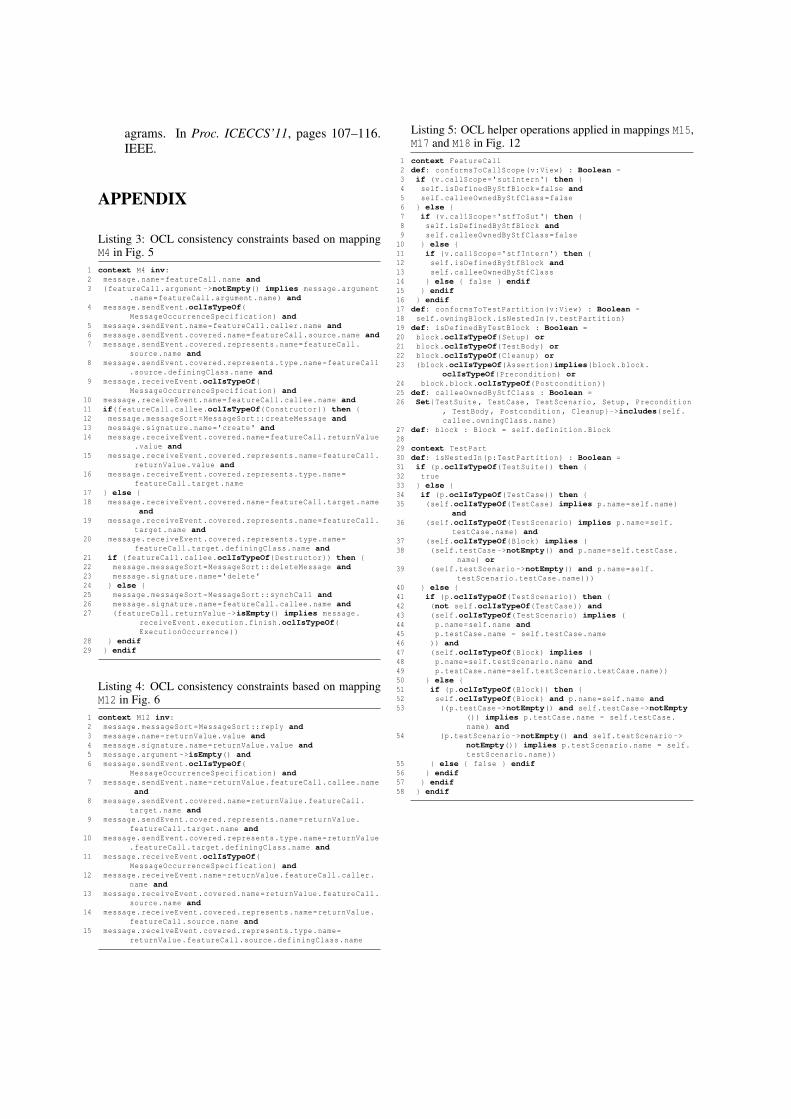
APPENDIX
Listing 3: OCL consistency constraints based on mappingM4 in Fig. 5
1 context M4 inv:2 message.name=featureCall.name and3 (featureCall.argument ->notEmpty() implies message.argument
.name=featureCall.argument.name) and4 message.sendEvent.oclIsTypeOf(
MessageOccurrenceSpecification) and5 message.sendEvent.name=featureCall.caller.name and6 message.sendEvent.covered.name=featureCall.source.name and7 message.sendEvent.covered.represents.name=featureCall.
source.name and8 message.sendEvent.covered.represents.type.name=featureCall
.source.definingClass.name and9 message.receiveEvent.oclIsTypeOf(
MessageOccurrenceSpecification) and10 message.receiveEvent.name=featureCall.callee.name and11 if(featureCall.callee.oclIsTypeOf(Constructor)) then {12 message.messageSort=MessageSort::createMessage and13 message.signature.name='create' and14 message.receiveEvent.covered.name=featureCall.returnValue
.value and15 message.receiveEvent.covered.represents.name=featureCall.
returnValue.value and16 message.receiveEvent.covered.represents.type.name=
featureCall.target.name17 } else {18 message.receiveEvent.covered.name=featureCall.target.name
and19 message.receiveEvent.covered.represents.name=featureCall.
target.name and20 message.receiveEvent.covered.represents.type.name=
featureCall.target.definingClass.name and21 if (featureCall.callee.oclIsTypeOf(Destructor)) then {22 message.messageSort=MessageSort::deleteMessage and23 message.signature.name='delete'24 } else {25 message.messageSort=MessageSort::synchCall and26 message.signature.name=featureCall.callee.name and27 (featureCall.returnValue ->isEmpty() implies message.
receiveEvent.execution.finish.oclIsTypeOf(ExecutionOccurrence))
28 } endif29 } endif
Listing 4: OCL consistency constraints based on mappingM12 in Fig. 6
1 context M12 inv:2 message.messageSort=MessageSort::reply and3 message.name=returnValue.value and4 message.signature.name=returnValue.value and5 message.argument ->isEmpty() and6 message.sendEvent.oclIsTypeOf(
MessageOccurrenceSpecification) and7 message.sendEvent.name=returnValue.featureCall.callee.name
and8 message.sendEvent.covered.name=returnValue.featureCall.
target.name and9 message.sendEvent.covered.represents.name=returnValue.
featureCall.target.name and10 message.sendEvent.covered.represents.type.name=returnValue
.featureCall.target.definingClass.name and11 message.receiveEvent.oclIsTypeOf(
MessageOccurrenceSpecification) and12 message.receiveEvent.name=returnValue.featureCall.caller.
name and13 message.receiveEvent.covered.name=returnValue.featureCall.
source.name and14 message.receiveEvent.covered.represents.name=returnValue.
featureCall.source.name and15 message.receiveEvent.covered.represents.type.name=
returnValue.featureCall.source.definingClass.name
Listing 5: OCL helper operations applied in mappings M15,M17 and M18 in Fig. 12
1 context FeatureCall2 def: conformsToCallScope(v:View) : Boolean =3 if (v.callScope='sutIntern') then {4 self.isDefinedByStfBlock=false and5 self.calleeOwnedByStfClass=false6 } else {7 if (v.callScope='stfToSut') then {8 self.isDefinedByStfBlock and9 self.calleeOwnedByStfClass=false10 } else {11 if (v.callScope='stfIntern') then {12 self.isDefinedByStfBlock and13 self.calleeOwnedByStfClass14 } else { false } endif15 } endif16 } endif17 def: conformsToTestPartition(v:View) : Boolean =18 self.owningBlock.isNestedIn(v.testPartition)19 def: isDefinedByTestBlock : Boolean =20 block.oclIsTypeOf(Setup) or21 block.oclIsTypeOf(TestBody) or22 block.oclIsTypeOf(Cleanup) or23 (block.oclIsTypeOf(Assertion)implies(block.block.
oclIsTypeOf(Precondition) or24 block.block.oclIsTypeOf(Postcondition))25 def: calleeOwnedByStfClass : Boolean =26 Set{TestSuite , TestCase , TestScenario , Setup , Precondition
, TestBody , Postcondition , Cleanup}->includes(self.callee.owningClass.name)
27 def: block : Block = self.definition.Block2829 context TestPart30 def: isNestedIn(p:TestPartition) : Boolean =31 if (p.oclIsTypeOf(TestSuite)) then {32 true33 } else {34 if (p.oclIsTypeOf(TestCase)) then {35 (self.oclIsTypeOf(TestCase) implies p.name=self.name)
and36 (self.oclIsTypeOf(TestScenario) implies p.name=self.
testCase.name) and37 (self.oclIsTypeOf(Block) implies (38 (self.testCase ->notEmpty() and p.name=self.testCase.
name) or39 (self.testScenario ->notEmpty() and p.name=self.
testScenario.testCase.name)))40 } else {41 if (p.oclIsTypeOf(TestScenario)) then {42 (not self.oclIsTypeOf(TestCase)) and43 (self.oclIsTypeOf(TestScenario) implies (44 p.name=self.name and45 p.testCase.name = self.testCase.name46 )) and47 (self.oclIsTypeOf(Block) implies (48 p.name=self.testScenario.name and49 p.testCase.name=self.testScenario.testCase.name))50 } else {51 if (p.oclIsTypeOf(Block)) then {52 self.oclIsTypeOf(Block) and p.name=self.name and53 ((p.testCase ->notEmpty() and self.testCase ->notEmpty
()) implies p.testCase.name = self.testCase.name) and
54 (p.testScenario ->notEmpty() and self.testScenario ->notEmpty()) implies p.testScenario.name = self.testScenario.name))
55 } else { false } endif56 } endif57 } endif58 } endif