an approach for runtime- modifiable behavior control of humanoid
TRANSCRIPT

An Approach for Runtime-Modifiable Behavior Controlof Humanoid Rescue RobotsEin Verfahren zur Steuerung humanoider Rettungsroboter durch zur Laufzeit modifizierbareVerhaltenMaster-Thesis von Philipp SchillingerTag der Einreichung:
1. Gutachten: Prof. Dr. Oskar von Stryk2. Gutachten: Dipl.-Inform. Stefan Kohlbrecher
An Approach for Runtime- Modifiable Behavior Control of Humanoid Rescue RobotsEin Verfahren zur Steuerung humanoider Rettungsroboter durch zur Laufzeit modifizierbareVerhalten
Vorgelegte Master-Thesis von Philipp Schillinger
1. Gutachten: Prof. Dr. Oskar von Stryk2. Gutachten: Dipl.-Inform. Stefan Kohlbrecher
Tag der Einreichung:
Technische Universität DarmstadtFachbereich Informatik
Fachgebiet Simulation, Systemoptimierung und Robotik (SIM)Prof. Dr. Oskar von Stryk
Erklärung zur Master-Thesis
Hiermit versichere ich, die vorliegende Master-Thesis ohne Hilfe Dritter nur mitden angegebenen Quellen und Hilfsmitteln angefertigt zu haben. Alle Stellen, dieaus Quellen entnommen wurden, sind als solche kenntlich gemacht. Diese Arbeithat in gleicher oder ähnlicher Form noch keiner Prüfungsbehörde vorgelegen.
Darmstadt, den 14. April 2015
(Philipp Schillinger)
i

Abstract
This thesis describes a novel approach for modification of robot behaviors during runtime. Ex-isting high-level robot control has very limited adaptability regarding unexpected disturbances.Possible uncertainties have to be known and explicitly considered in advance by defining strate-gies of how to react to these. This requirement confines the development of robust robots as forexample required in complex and unstructured disaster mitigation scenarios. In order to over-come this limitation and to facilitate the development of more flexible high-level robot behaviorcontrol, the approach developed in this thesis enables to change the whole structure of behav-iors even while they are executed. Therefore, the operator is able to incorporate situationalknowledge gained during execution, and thus to compensate insufficient a priori knowledgeabout the status of the environment. The approach is proposed based on modeling behaviorsas hierarchical state machines, allowing for modular composition and intuitive specification indifferent levels of abstraction. Detailed monitoring of the state of execution and occurred errorsassists the operator when giving commands and adjusting the level of autonomy, utilizing theindividual capabilities of both robot and operator in a cooperative manner. Nevertheless, thedeveloped framework is able to cope with severe restrictions on the communication channel tothe robot and is robust regarding runtime failure. In addition, verification of specified behaviorsgreatly reduces the risk of failure. As part of this thesis, the behavior engine FlexBE has beendeveloped in order to implement and refine the promoted concepts. It comes with a compre-hensive user interface and behavior editor and is practically applied in the upcoming DARPARobotics Challenge Finals.
ii

Zusammenfassung
Die vorliegende Arbeit beschreibt einen neuartigen Ansatz zur Anpassung des Roboterverhal-tens während der Laufzeit. Aktuelle Verfahren zur Steuerung von Robotern sind nur sehr ein-geschränkt in der Lage, auf unerwartete Störungen zu reagieren. Mögliche Unsicherheiten undStrategien, um diese zu überwinden, müssen im Voraus bekannt sein und explizit berücksichtigtwerden. Diese Anforderung schränkt die Entwicklung robuster Roboter, wie sie beispielsweise inkomplexen und unstrukturierten Krisenszenarien erforderlich sind, deutlich ein. Um diese Ein-schränkung zu überwinden und die Entwicklung flexiblerer Verhaltenssteuerung von Roboternzu erleichtern, ermöglicht es der in dieser Arbeit entwickelte Ansatz, die komplette Strukturvon Verhalten zu ändern, selbst während diese bereits ausgeführt werden. Das erlaubt es demBediener, zur Laufzeit gesammeltes Wissen über die Situation des Roboters einzubringen undso unzureichendes Ausgangswissen auszugleichen. Der verfolgte Ansatz basiert auf der Wahlvon hierarchischen Zustandsautomaten zur Modellierung von Verhalten, was eine modulareund intuitive Definition in verschiedenen Abstraktionsschichten erlaubt. Detaillierte Informa-tionen über den aktuellen Laufzeitstatus und aufgetretene Fehler unterstützen den Bedienerdabei, Befehle zu senden und den Autonomiegrad des Roboters anzupassen. Dadurch könnendie individuellen Fähigkeiten von Roboter und Bediener für eine kooperative Herangehensweisegenutzt werden. Dennoch ist das System in der Lage, mit starken Beschränkungen hinsichtlichder Kommunikation mit dem Roboter umzugehen und robust auf Laufzeitfehler zu reagieren.Das Risiko solcher Fehler wird zudem durch die Verifizierung von Verhaltensdefinitionen deut-lich reduziert. Als Teil dieser Arbeit wurde auch die Verhaltensengine FlexBE entwickelt, um dieerarbeiteten Konzepte umzusetzen und zu verbessern. FlexBE beinhaltet eine umfangreiche Be-nutzeroberfläche sowie einen Verhaltenseditor und wird im bevorstehenden Finale der DARPARobotics Challenge eingesetzt.
iii

Acknowledgements
In the course of this thesis, many people provided support, contributed with helpful discussionsabout the concept, and practically used the implemented framework FlexBE already in earlystages of development. First and foremost, I would like to thank my advisors Prof. Dr. Oskarvon Stryk and Stefan Kohlbrecher, not only for their feedback and suggestions regarding thisthesis, but also for being co-authors of the submitted research paper presenting some of theconcepts developed as part of this thesis.
Furthermore, I thank Spyros Maniatopoulos and the Verifiable Robotics Research Group lead byProf. Hadas Kress-Gazit for their hospitality during my stays at Cornell University, and especiallySpyros Maniatopoulos for the joint work on combining the developed framework with behaviorsynthesis and for extensively using FlexBE, helping to knock out all those little hidden flaws inearly versions.
Moreover, thank goes to David Conner and the DRC project team of TORC Robotics for givingus a solid infrastructure for software development and doing their best to provide a work-ing robot during all of the three test phases at Blacksburg, despite the technical difficultiesintroduced by switching to the new version of ATLAS.
Additionally, I would like to thank all participants of the regular behavior control meetingsfor the helpful and leading discussions regarding design choices and required features. Also,I thank Moritz Schappler, Jonathan Vorndamme, and the rest of their team at the Institute ofAutomatic Control at Leibniz University Hanover for extensively using FlexBE for their systemidentification tests.
Finally, I would like to thank all members of Team ViGIR providing functionality for the im-plementation of behavior states, especially Stefan Kohlbrecher, Alberto Romay, and AlexanderStumpf at SIM, TU Darmstadt, and all members developing and assisting development of be-haviors based on FlexBE and relying on the previously mentioned states.
iv
Intelligence is the ability to adapt to change.
— Stephen Hawking
v

Contents
1 Introduction 11.1 Motivation . . . . . . . . . . . . . . . . . . . . . . . . . . . . . . . . . . . . . . . . . . . . 41.2 Contributions . . . . . . . . . . . . . . . . . . . . . . . . . . . . . . . . . . . . . . . . . . 51.3 FlexBE . . . . . . . . . . . . . . . . . . . . . . . . . . . . . . . . . . . . . . . . . . . . . . . 71.4 Thesis Overview . . . . . . . . . . . . . . . . . . . . . . . . . . . . . . . . . . . . . . . . . 8
2 State of Research 92.1 Behavior Control Approaches . . . . . . . . . . . . . . . . . . . . . . . . . . . . . . . . . 9
2.1.1 Autonomous Behaviors . . . . . . . . . . . . . . . . . . . . . . . . . . . . . . . . 102.1.2 Human Robot Interaction . . . . . . . . . . . . . . . . . . . . . . . . . . . . . . 122.1.3 Cooperative Behaviors . . . . . . . . . . . . . . . . . . . . . . . . . . . . . . . . 14
2.2 Behavior Verification . . . . . . . . . . . . . . . . . . . . . . . . . . . . . . . . . . . . . . 162.2.1 Behavior Synthesis . . . . . . . . . . . . . . . . . . . . . . . . . . . . . . . . . . . 17
2.3 Runtime Modifications . . . . . . . . . . . . . . . . . . . . . . . . . . . . . . . . . . . . . 182.4 Existing Behavior Frameworks . . . . . . . . . . . . . . . . . . . . . . . . . . . . . . . . 19
2.4.1 XABSL . . . . . . . . . . . . . . . . . . . . . . . . . . . . . . . . . . . . . . . . . . 192.4.2 RoboCup Frameworks . . . . . . . . . . . . . . . . . . . . . . . . . . . . . . . . . 202.4.3 SMACH . . . . . . . . . . . . . . . . . . . . . . . . . . . . . . . . . . . . . . . . . . 212.4.4 Flor Behavior Engine . . . . . . . . . . . . . . . . . . . . . . . . . . . . . . . . . 22
3 Concepts 243.1 Definitions . . . . . . . . . . . . . . . . . . . . . . . . . . . . . . . . . . . . . . . . . . . . 243.2 Operator Interaction . . . . . . . . . . . . . . . . . . . . . . . . . . . . . . . . . . . . . . 27
3.2.1 Behavior Mirror . . . . . . . . . . . . . . . . . . . . . . . . . . . . . . . . . . . . 283.2.2 Behavior Input . . . . . . . . . . . . . . . . . . . . . . . . . . . . . . . . . . . . . 29
3.3 Runtime Modifications . . . . . . . . . . . . . . . . . . . . . . . . . . . . . . . . . . . . . 303.3.1 Consistency . . . . . . . . . . . . . . . . . . . . . . . . . . . . . . . . . . . . . . . 313.3.2 Behavior Update . . . . . . . . . . . . . . . . . . . . . . . . . . . . . . . . . . . . 33
3.4 Behavior Development . . . . . . . . . . . . . . . . . . . . . . . . . . . . . . . . . . . . . 333.5 State Constraints . . . . . . . . . . . . . . . . . . . . . . . . . . . . . . . . . . . . . . . . 34
4 Behavior Engine 364.1 Foundations . . . . . . . . . . . . . . . . . . . . . . . . . . . . . . . . . . . . . . . . . . . 37
4.1.1 Behavior Specification . . . . . . . . . . . . . . . . . . . . . . . . . . . . . . . . . 374.1.2 Operator Interaction . . . . . . . . . . . . . . . . . . . . . . . . . . . . . . . . . . 38
4.2 Onboard Executive . . . . . . . . . . . . . . . . . . . . . . . . . . . . . . . . . . . . . . . 394.2.1 Inheritance Chain . . . . . . . . . . . . . . . . . . . . . . . . . . . . . . . . . . . 414.2.2 State Implementation . . . . . . . . . . . . . . . . . . . . . . . . . . . . . . . . . 45
4.3 Code Transfer . . . . . . . . . . . . . . . . . . . . . . . . . . . . . . . . . . . . . . . . . . 464.4 Behavior Switch . . . . . . . . . . . . . . . . . . . . . . . . . . . . . . . . . . . . . . . . . 474.5 Monitoring . . . . . . . . . . . . . . . . . . . . . . . . . . . . . . . . . . . . . . . . . . . . 49
vi

5 Behavior Operation 515.1 Approach . . . . . . . . . . . . . . . . . . . . . . . . . . . . . . . . . . . . . . . . . . . . . 51
5.1.1 Infrastructure . . . . . . . . . . . . . . . . . . . . . . . . . . . . . . . . . . . . . . 525.1.2 Operator Views . . . . . . . . . . . . . . . . . . . . . . . . . . . . . . . . . . . . . 55
5.2 Statemachine Editor . . . . . . . . . . . . . . . . . . . . . . . . . . . . . . . . . . . . . . 575.2.1 User Interaction . . . . . . . . . . . . . . . . . . . . . . . . . . . . . . . . . . . . 585.2.2 Integration of States . . . . . . . . . . . . . . . . . . . . . . . . . . . . . . . . . . 605.2.3 Code Generation . . . . . . . . . . . . . . . . . . . . . . . . . . . . . . . . . . . . 62
5.3 Runtime Control . . . . . . . . . . . . . . . . . . . . . . . . . . . . . . . . . . . . . . . . . 645.3.1 Control Interface . . . . . . . . . . . . . . . . . . . . . . . . . . . . . . . . . . . . 675.3.2 Communication . . . . . . . . . . . . . . . . . . . . . . . . . . . . . . . . . . . . 70
6 Evaluation 736.1 Operator Experience . . . . . . . . . . . . . . . . . . . . . . . . . . . . . . . . . . . . . . 73
6.1.1 Behavior Development . . . . . . . . . . . . . . . . . . . . . . . . . . . . . . . . 746.1.2 Behavior Execution . . . . . . . . . . . . . . . . . . . . . . . . . . . . . . . . . . 75
6.2 Behavior Performance . . . . . . . . . . . . . . . . . . . . . . . . . . . . . . . . . . . . . 766.3 DARPA Robotics Challenge . . . . . . . . . . . . . . . . . . . . . . . . . . . . . . . . . . 79
6.3.1 ATLAS . . . . . . . . . . . . . . . . . . . . . . . . . . . . . . . . . . . . . . . . . . 816.3.2 THOR-MANG . . . . . . . . . . . . . . . . . . . . . . . . . . . . . . . . . . . . . . 82
6.4 Future Work . . . . . . . . . . . . . . . . . . . . . . . . . . . . . . . . . . . . . . . . . . . 836.4.1 Synthesis Integration . . . . . . . . . . . . . . . . . . . . . . . . . . . . . . . . . 836.4.2 Web-based Solution . . . . . . . . . . . . . . . . . . . . . . . . . . . . . . . . . . 846.4.3 Parallel Execution . . . . . . . . . . . . . . . . . . . . . . . . . . . . . . . . . . . 856.4.4 Multiple Robots . . . . . . . . . . . . . . . . . . . . . . . . . . . . . . . . . . . . . 86
7 Conclusion 87
Bibliography 89
Appendix 93A.1 List of Developed States . . . . . . . . . . . . . . . . . . . . . . . . . . . . . . . . . . . . 94
A.1.1 flexbe_states . . . . . . . . . . . . . . . . . . . . . . . . . . . . . . . . . . . . . . 94A.1.2 flexbe_atlas_states . . . . . . . . . . . . . . . . . . . . . . . . . . . . . . . . . . . 95
A.2 Evaluation of Behavior Logfiles . . . . . . . . . . . . . . . . . . . . . . . . . . . . . . . . 97A.3 Example State Implementation . . . . . . . . . . . . . . . . . . . . . . . . . . . . . . . . 98A.4 Exploration Demo Behavior . . . . . . . . . . . . . . . . . . . . . . . . . . . . . . . . . . 100A.5 Communication Channel Topics . . . . . . . . . . . . . . . . . . . . . . . . . . . . . . . 101A.6 FlexBE Tutorials . . . . . . . . . . . . . . . . . . . . . . . . . . . . . . . . . . . . . . . . . 102
A.6.1 Creating a New Behavior . . . . . . . . . . . . . . . . . . . . . . . . . . . . . . . 103A.6.2 Using the Statemachine Editor . . . . . . . . . . . . . . . . . . . . . . . . . . . 106A.6.3 Execution of a Behavior . . . . . . . . . . . . . . . . . . . . . . . . . . . . . . . . 110
Contents vii

1 Introduction
Robotics research showed significant progress during recent years. Individual robot capabilitiessuch as grasp planning for enhanced manipulation, reliable bipedal locomotion, or advancedtechniques to perceive the environment, have been significantly improved and enable applyingrobots to an even greater extend to tasks where they can support humans or replace them indangerous situations. However, most of the current robot applications are very domain specific.They are tailored to specific tasks and are not arbitrarily applicable, while often based on oneor two main capabilities. For example, a common service robot is focused on human robotinteraction, but it is only able to navigate on flat ground. A robot equipped with a multitudeof sensors might be able to detect objects of interest in its vicinity, but lacks in autonomousmanipulation, and thus can only report its findings.
The assumed scenarios are typically well defined. It is known in advance what is requiredto solve a task, and also possible sources of failure are known in detail. Furthermore, if theproblem is too complex to be precisely modeled, teleoperation of the robot agents is a commonapproach. Unfortunately, scenarios in rescue robotics are often much more severe. Besides typ-ically performing on tasks of critical importance, rescue robots face much harder restrictionsregarding the ability to model their expected environment and to communicate with them dur-ing task execution. While the former restriction limits the applicability of approaches relying onautonomous robot behavior, the latter prevents conventional teleoperation. In order to addresssuch tasks a hybrid approach is required instead. The robot and its human operator need tojointly work together and support each other when possible. In addition, precise a priori knowl-edge of the circumstances of such tasks is rarely available, which makes it difficult to design anapproach in advance.
In order to encourage research in this important field of robotics, the United States DefenseAdvanced Research Projects Agency1 (DARPA) proposed the DARPA Robotics Challenge2 (DRC).
Figure 1.1: High-resolution photos taken by one of the robots at Fukushima [30].
1 http://www.darpa.mil (03/21/2015)2 http://www.theroboticschallenge.org/ (03/21/2015)
1

Figure 1.2: Overview of the tasks in the DRC Finals, illustrated by James Provost.
Motivated by the earthquake and tsunami which caused significant damage to the FukushimaDaiichi nuclear plant in 2011, this challenge defines a sequence of tasks required to mitigatesimilar disasters. At this time, robots were deployed at the destructed nuclear plant with the goalto investigate the site and to avert further danger. Despite all effort, unexpected limitations suchas narrow stairs, and disturbances like debris blocking the way prevented successful executionof the conducted missions.
An overview of the tasks of the DRC Finals is given in figure 1.2. After approaching the site bydriving a vehicle and egressing it, the robot has to enter the building by opening a door. Inside,the robot will face a number of different tasks such as negotiating debris, cutting a hole in a walland opening a valve behind it, or plugging in a fire hose. Finally, the robot will have to climbup stairs and solve a previously unknown manipulation task. The whole course has to be solvedin a single run with a time limit of one hour. During the task, no wired connection to the robotis allowed, neither for communication nor as power supply. As further restrictions, the wirelessconnection to the robot is strictly limited to incorporate the expected conditions of a disasterresponse scenario and to prevent teleoperation and the availability of detailed environmentaldata. Especially indoors, communication is barely available and may occasionally face blackouts.
Team ViGIR3 (standing for Virginia-Germany Interdisciplinary Robotics) is one of the TrackB teams participating at the DARPA Robotics Challenge. While Track A teams receive DARPA3 http://www.teamvigir.org/ (03/31/2015)
2

funding to develop an own robot including software, Track B teams are funded for sole softwaredevelopment and are provided an ATLAS4 robot developed by Boston Dynamics5. In addition,further teams can participate by relying on external funding. The challenge has been proposedin early 2012 and started in October 2012. The first competition, the Virtual Robotics Challenge(VRC) was held in June 2013 between the teams without an own robot in order to determinethe top teams to receive an ATLAS robot. Team ViGIR was ranked 6th out of the 126 registeredteams and thus qualified to continue participation at the DRC and got an ATLAS robot. InDecember 2013, the DRC Trials formed the first competition of the DARPA Robotics Challengeincluding the real robots and the Track A teams. Team ViGIR ranked 10th out of the remaining16 teams and is now facing the DRC Finals, held in June 2015.
The team was initially formed by TORC Robotics6, the Simulation, Systems Optimization andRobotics Group7 at TU Darmstadt, and the 3D Interaction Group8 at Virgina Tech. After the VRC,the Robotics and Human Control Systems Lab9 at Oregon State University joined the team, andon track to the DRC Finals, the Verifiable Robotics Research Group10 at Cornell University andthe Institute for Automatic Control11 at Leibniz University Hanover joined as well. The softwareof Team ViGIR is based on ROS12 and leverages several open-source software frameworks. Themain part of the software runs on the robot while the operator interacts with the part running atthe Operator Control Station (OCS). An overview of the system as used for the trials is given by
Figure 1.3: Florian, the ATLAS robot of Team ViGIR, at the DRC Trials [22].
4 http://www.bostondynamics.com/robot_Atlas.html (03/31/2015)5 http://www.bostondynamics.com/ (03/31/2015)6 http://www.torcrobotics.com/ (03/31/2015)7 http://www.sim.informatik.tu-darmstadt.de/ (03/31/2015)8 https://research.cs.vt.edu/3di/ (03/31/2015)9 http://mime.oregonstate.edu/research/rhcs/ (03/31/2015)10 http://verifiablerobotics.com/ (03/31/2015)11 http://www.irt.uni-hannover.de/ (03/31/2015)12 http://www.ros.org/ (03/31/2015)
3
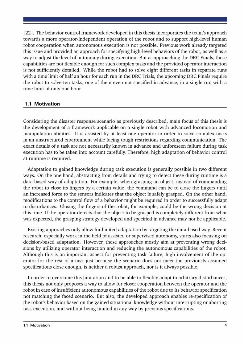
[22]. The behavior control framework developed in this thesis incorporates the team’s approachtowards a more operator-independent operation of the robot and to support high-level humanrobot cooperation when autonomous execution is not possible. Previous work already targetedthis issue and provided an approach for specifying high-level behaviors of the robot, as well as away to adjust the level of autonomy during execution. But as approaching the DRC Finals, thesecapabilities are not flexible enough for such complex tasks and the provided operator interactionis not sufficiently detailed. While the robot had to solve eight different tasks in separate runswith a time limit of half an hour for each run in the DRC Trials, the upcoming DRC Finals requirethe robot to solve ten tasks, one of them even not specified in advance, in a single run with atime limit of only one hour.
1.1 Motivation
Considering the disaster response scenario as previously described, main focus of this thesis isthe development of a framework applicable on a single robot with advanced locomotion andmanipulation abilities. It is assisted by at least one operator in order to solve complex tasksin an unstructured environment while facing tough restrictions regarding communication. Theexact details of a task are not necessarily known in advance and unforeseen failure during taskexecution has to be taken into account carefully. Therefore, high adaptation of behavior controlat runtime is required.
Adaptation to gained knowledge during task execution is generally possible in two differentways. On the one hand, abstracting from details and trying to detect these during runtime is adata-based way of adaptation. For example, when grasping an object, instead of commandingthe robot to close its fingers by a certain value, the command can be to close the fingers untilan increased force to the sensors indicates that the object is safely grasped. On the other hand,modifications to the control flow of a behavior might be required in order to successfully adaptto disturbances. Closing the fingers of the robot, for example, could be the wrong decision atthis time. If the operator detects that the object to be grasped is completely different from whatwas expected, the grasping strategy developed and specified in advance may not be applicable.
Existing approaches only allow for limited adaptation by targeting the data-based way. Recentresearch, especially work in the field of assisted or supervised autonomy, starts also focusing ondecision-based adaptation. However, these approaches mostly aim at preventing wrong deci-sions by utilizing operator interaction and reducing the autonomous capabilities of the robot.Although this is an important aspect for preventing task failure, high involvement of the op-erator for the rest of a task just because the scenario does not meet the previously assumedspecifications close enough, is neither a robust approach, nor is it always possible.
In order to overcome this limitation and to be able to flexibly adapt to arbitrary disturbances,this thesis not only proposes a way to allow for closer cooperation between the operator and therobot in case of insufficient autonomous capabilities of the robot due to its behavior specificationnot matching the faced scenario. But also, the developed approach enables re-specification ofthe robot’s behavior based on the gained situational knowledge without interrupting or abortingtask execution, and without being limited in any way by previous specifications.
1.1 Motivation 4

(a) (b)
Figure 1.4: Possible scenario where the control flow has to be adjusted: Instead of using the yellow drillas planned in advance, a more powerful drill is detected and preferred by the operator. Thebehavior defined in (b) does not account for choosing between drills. (a) taken from [22].
Motivated by the complex scenarios including a high level of uncertainty as faced by rescuerobots, the ability to modify behaviors flexibly during runtime is a powerful feature to improvetask performance and to be able to develop significantly more adaptable robots. However,changing the specifications of a behavior during its execution also makes it prone to failure bypossibly introducing new errors. This is especially likely considering the high pressure situationin which the operator has to specify the changes, and his limited possibilities to test the newspecifications in advance because the robot is already in the field. Thus, it is an important aspectof this thesis to reduce the sources of failure by assisting the operator in developing the behavior,and to automate as much as possible while also incorporating verification checks.
Finally, further challenges of modifying behaviors during runtime have to be addressed. Itis very important to not distract the operator from supervising the actions taken by the robot.Considering that the circumstances in which a modification of the robot behavior is requiredtypically also require careful supervision and high attention by the operator, specification of themodifications has to be as easy and intuitive as possible. In addition, choosing a multi-operatorapproach is very advisable for such situations. Furthermore, even small adjustments of thebehavior require time. Although the scenario itself may put time constraints on task execution,modifying the behavior of the robot should not add further time pressure. For this reason, theoperator needs to be able to specify a point in behavior execution where the robot will pauseuntil the changes are applied, while keeping to execute the correct behavior as long as possiblein parallel to defining the changes in order to still make progress on the task.
1.2 Contributions
As discussed in the previous section, this thesis mainly addresses the support of runtime modifi-cations of robot behaviors. But while these adaptations offer great flexibility when consideringthe capability of reacting to unforeseen difficulties or imminent failure, they come along witha considerably high risk regarding reliability. When changing a behavior specification duringruntime, the new version of the respective behavior is very prone to errors since it can not be
1.2 Contributions 5
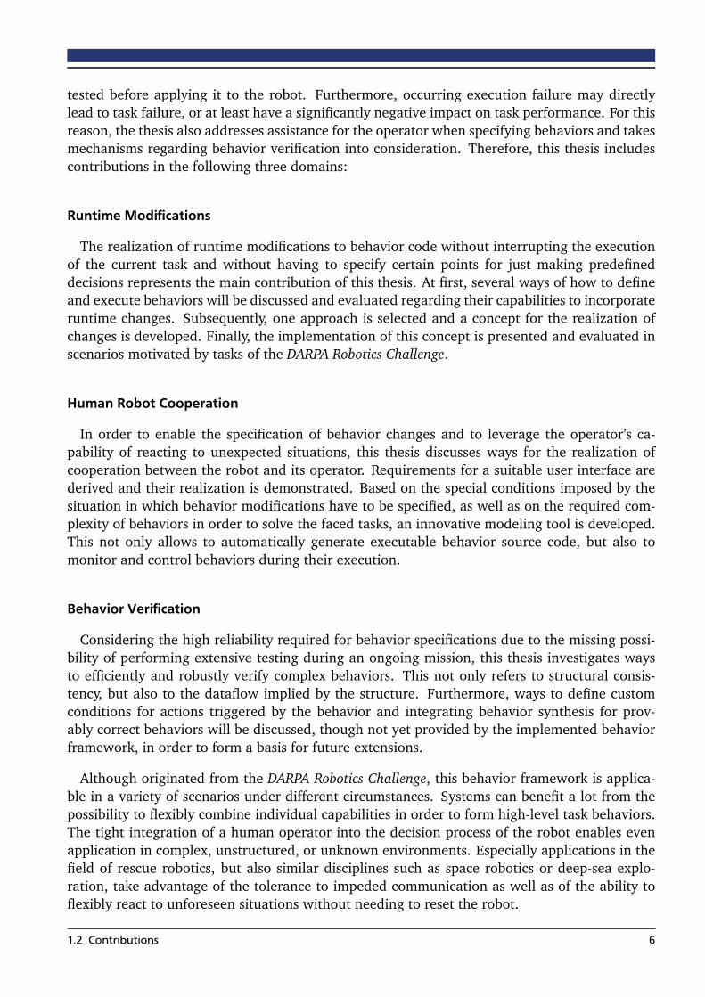
tested before applying it to the robot. Furthermore, occurring execution failure may directlylead to task failure, or at least have a significantly negative impact on task performance. For thisreason, the thesis also addresses assistance for the operator when specifying behaviors and takesmechanisms regarding behavior verification into consideration. Therefore, this thesis includescontributions in the following three domains:
Runtime Modifications
The realization of runtime modifications to behavior code without interrupting the executionof the current task and without having to specify certain points for just making predefineddecisions represents the main contribution of this thesis. At first, several ways of how to defineand execute behaviors will be discussed and evaluated regarding their capabilities to incorporateruntime changes. Subsequently, one approach is selected and a concept for the realization ofchanges is developed. Finally, the implementation of this concept is presented and evaluated inscenarios motivated by tasks of the DARPA Robotics Challenge.
Human Robot Cooperation
In order to enable the specification of behavior changes and to leverage the operator’s ca-pability of reacting to unexpected situations, this thesis discusses ways for the realization ofcooperation between the robot and its operator. Requirements for a suitable user interface arederived and their realization is demonstrated. Based on the special conditions imposed by thesituation in which behavior modifications have to be specified, as well as on the required com-plexity of behaviors in order to solve the faced tasks, an innovative modeling tool is developed.This not only allows to automatically generate executable behavior source code, but also tomonitor and control behaviors during their execution.
Behavior Verification
Considering the high reliability required for behavior specifications due to the missing possi-bility of performing extensive testing during an ongoing mission, this thesis investigates waysto efficiently and robustly verify complex behaviors. This not only refers to structural consis-tency, but also to the dataflow implied by the structure. Furthermore, ways to define customconditions for actions triggered by the behavior and integrating behavior synthesis for prov-ably correct behaviors will be discussed, though not yet provided by the implemented behaviorframework, in order to form a basis for future extensions.
Although originated from the DARPA Robotics Challenge, this behavior framework is applica-ble in a variety of scenarios under different circumstances. Systems can benefit a lot from thepossibility to flexibly combine individual capabilities in order to form high-level task behaviors.The tight integration of a human operator into the decision process of the robot enables evenapplication in complex, unstructured, or unknown environments. Especially applications in thefield of rescue robotics, but also similar disciplines such as space robotics or deep-sea explo-ration, take advantage of the tolerance to impeded communication as well as of the ability toflexibly react to unforeseen situations without needing to reset the robot.
1.2 Contributions 6

1.3 FlexBE
As result of this thesis, the behavior engine FlexBE (standing for Flexible Behavior Engine) hasbeen developed, based on the discussed concepts and defined requirements. It includes a userinterface combining an advanced behavior editor and a behavior control station for supervisingbehaviors during runtime. While the engine itself is applicable for even underspecified tasksin unstructured environments, the interface is designed for use by non-expert operators anddevelopers as well. Especially when specifying complex behaviors, even a developer familiarwith robotics will typically not have detailed knowledge regarding all the individual capabilitiesinvolved for solving the task. Thus, a modular and abstract composition of behaviors is possibleusing FlexBE, with a strong focus on assisting the developer by providing relevant documenta-tion. Even advanced behaviors can be specified and executed without manually writing a singleline of code, although editing source code is possible in order to not limit expert users.
In addition to solely providing a way for specifying complex behaviors, FlexBE also managestheir execution on a remote robot agent. It includes operator interaction for close human robotcollaboration by design and deals with issues such as keeping track of the remote execution, orsending commands and monitoring their execution. Switching flexibly from the currently exe-cuted version of a behavior to a new one is possible without restarting the robot or interruptingtask progress, in order to take gained knowledge regarding the task into account. Even if abehavior unexpectedly fails during its execution, the robustness of FlexBE allows the operatorto correct it on-the-fly or to select a different behavior to be executed instead.
Figure 1.5: Defining a behavior state machine in the FlexBE editor.
1.3 FlexBE 7

Figure 1.6: Supervising a behavior during its execution using the FlexBE runtime control view.
1.4 Thesis Overview
After having given a first impression of the topic and the motivation behind this thesis in thischapter, the thesis is divided into four parts, presented in chapters 2-6. At first, chapter 2 gives anoverview of the current state in relevant fields of research. Main emphasize is placed on behaviorcontrol, but approaches of behavior synthesis and verification, as well as runtime modificationsare touched in order to be considered for the newly developed approach contributed by thisthesis. Next, chapter 3 focuses on the underlying concepts and discusses the theoretical back-ground in an abstract manner. After summarizing the available basis provided by previous workin a uniform way, concepts regarding operator interaction and runtime modifications are addedon top. Finally, consequences for behavior development are discussed.
The third part, chapters 4 and 5, presents various aspects of the implemented software basedon the developed concepts. Chapter 4 targets the onboard behavior engine and shows howexecution of behaviors is solved by FlexBE and how the process of behavior switching duringruntime is integrated. Subsequently, after an initial discussion regarding the detailed approachspecific to the user interface, chapter 5 presents the behavior control station, including codegeneration of behaviors and controlling their execution.
Chapter 6 finally concludes this thesis with an evaluation of the developed behavior controlframework. Both, the development of new behaviors and the provided support during theirexecution, is investigated, and strengths as well as weaknesses are identified. Following, the ap-plication of this framework in the context of the DARPA Robotics Challenge on the robot platformsATLAS and THOR-MANG is presented. Finally, an outlook regarding further work is given.
1.4 Thesis Overview 8

2 State of Research
When speaking of behavior control, there are many ways to realize such a system. Nonetheless,there are core characteristics of a behavior control system which all approaches have in common,regardless of their different ways of realization. The main purpose of a behavior control systemtypically is to coordinate high-level decisions, select appropriate actions, and trigger recoveryfrom failure while assuming that the implementation of each single capability of the robot issolved separately and can be accessed by a common, known interface. Behaviors, in this context,refer to specific representations of strategies to address at least one of the three listed problems.
This chapter presents and discusses different approaches of such behavior control systems,especially varying with regard to the way how decisions are taken and how behaviors are rep-resented. Next, going towards runtime-modifiable behavior control, current work regardingbehavior synthesis and verification is presented, and it is discussed how these techniques cansupport the implementation of complex behaviors during runtime, considering the specific cir-cumstances as discussed in chapter 1.1 as well as their possible use to ensure consistency andcorrectness of defined behaviors.
Furthermore, ways to enable runtime modifications as required for the implementation ofbehavior updates are discussed, and relevant research is presented. The latter, due to the inno-vative character of this topic, is not specifically focused on robot behavior control. Last, selectedexisting frameworks are introduced. These can be used as a foundation for the frameworkdeveloped in this thesis and are discussed regarding their applicability.
2.1 Behavior Control Approaches
Classic behavior control approaches mainly focus on either teleoperation of single robots oras much autonomy as possible. Unfortunately, each of these characteristics comes along withits unique pitfalls and disadvantages. In order to overcome this conflict and incorporate thestrengths of each approach, recent work starts focusing on solutions to combine both paradigmsin an intelligent way, as for example summarized in [6].
This section presents the most relevant approaches for this thesis and discusses their advan-tages as well as their applicability for the given context. Furthermore, approaches which arenot directly applicable are discussed in order to evaluate some of their aspects and to learnfrom their results and experience. But runtime-modifiable behavior control also strongly de-pends on the ability to monitor and influence the execution of behaviors. Therefore, not onlybehavior control systems are presented, but also concepts regarding human robot interactionare discussed and it is evaluated how these paradigms can be incorporated by advanced assistedautonomy approaches of behavior control. This is especially relevant because the commandsan operator can give the robot have a high impact on task execution when speaking of runtimemodifications, and thus have to be given on a reliable basis.
9

2.1.1 Autonomous Behaviors
The main goal of autonomous behaviors is to remove the need for human operators by providingdecisions depending on available situational data. This includes the internal state of the robotas well as sensor data of its surroundings. The availability and reliability of this data is one ofthe factors which characterizes the requirements for a behavior control system. Especially thereliability has to be above a certain level in order to enable autonomous behaviors at all. If not,the human cognition is much better able to identify certain situations. Further characteristics ofa task which determine the type of behavior control are for example the complexity of the task,the number of tasks to be solved in parallel, the amount of robots involved, and the probabilityof failure or external interruptions. As already presented in chapter 1, the characteristics con-sidered in this thesis target a single robot solving a sequence of complex tasks while facing ahigh probability of failure in executing the desired actions.
In the context of the DARPA Robotics Challenge (DRC), many teams like IHMC [18] and WPI[10] used scripts to execute a series of predefined motions or relied on templates, as for exampledone by team HUBO [44], to provide known endeffector poses. These approaches are simpleand require a lot of knowledge and preparation in advance, at the same time struggling todeal with variations, uncertainty and failure. For example, WPI prepared a motion script forpicking up a piece of debris and moving it out of the way. In order to score the first point inthe corresponding task of the DRC Trials, it is required to remove at least five pieces. The scriptworked well for the first four pieces, but since the motion was predefined, the robot was unableto consider its environment and collided with a wall while trying to execute the script for thefifth time.
Another, more reactive approach, are the behavior-based systems as presented in [26] andillustrated by figure 2.1. Behavior, in this context, refers to relatively simple policies which areused to preserve or achieve a single property of the system. In order to solve the given tasks,
Figure 2.1: A typical behavior-based system, taken from [26].
2.1 Behavior Control Approaches 10

multiple of these policies are active in parallel and their output is combined in order to formthe overall behavior of the agent. As stated by [9], the reactive nature of these systems makesthem less appropriate for complex scenarios. Especially when a sequence of actions has to beexecuted, meaning the goal to be achieved by the behavior control system changes over time, apurely behavior-based approach is hard to apply.
This yields the need for more advanced strategies of how to combine single behaviors de-pending on the state of task execution and the environment of the agent. [25] uses a Bayesianframework for estimating the current state of the agent and selecting the appropriate behaviorwhen facing uncertainty regarding the environment. This approach not only helps to increasethe likelihood that the desired goal is achieved, but also keeps the complexity of action selec-tion relatively low. Action selection can also be targeted by approaches based on fuzzy logic forcombining multiple applicable policies as done by [23]. [15] proposes a fuzzy discrete eventsystem in order to coordinate between single policies.
When facing complex tasks, it is a trending and reasonable approach to use machine learningfor determining and parameterizing behaviors to achieve the desired goal. It is often combinedwith a behavior-based approach as described above. The advantage of such an approach is theremarkably low amount of required knowledge with regard to the details of the environmentwhich enables behaviors to be applicable under various circumstances. However, the influenc-ing aspects of a task have to be reliably identified and taken into consideration. Finally, thesystem has to be trained. This is often very time-consuming and typically requires multiple at-tempts on the task. [42] uses modular reinforcement learning for navigation, while the modularcharacteristic of this approach is used to reduce the learning time. [33] relies on hierarchicalabstraction in order to achieve the same goal. Given the scenario of rescue robotics, multipleattempts to solve a task while steadily learning and improving task performance is not desir-able. It may even be the case that task failure leads to completely losing access to the robot, asalready discussed in chapter 1. Therefore, machine learning approaches are not considered asapplicable for the given context.
A different, widely-used approach for specifying the top-level behavior of an agent is the use ofstate machines. The active state of the state machine somehow represents the situation currentlyfaced by the robot, while the state machine itself defines how to act in response. However, thereare many existing approaches relying on state machines for realization.
The system presented in [1], the approach of team NimbRo for the RoboCup1 Soccer com-petition, is one example for an autonomous behavior control system based on state machines.The system consists of two main parts, the State Controller Library (SC Library) and the Be-havior Control Framework (BC Framework). Both parts are independent in principle, but areused together to address a variety of situations. The SC Library internally holds a state queue,containing states which should be executed by the controller. Each state can modify this queuein order to perform transition. This means, there is no explicit definition of transitions, but thetransitions are encapsulated in the state execution instead. The BC Framework, on the otherhand, is realized similar to the behavior-based approach and uses the behaviors provided by theSC Library in order to compose more complex behaviors.
1 http://www.robocup.org/ (03/31/2015)
2.1 Behavior Control Approaches 11

In general, there are two different approaches of using actions in the context of state ma-chines. One approach is that actions are called when executing a transition between two states.This means that each state is determined by the runtime status of the robot, such as its cur-rent physical or logical properties. If one of these properties changes, it causes a transition andactions are selected and executed while transitioning to the subsequent state, resulting fromthe external property changes. Unfortunately, this approach is hardly able to react to failureor unexpected outcomes of the executed actions since the target state of a transition is alreadydefined. The second approach defines actions to happen while a state is active and transitionsonly point to possible subsequent states, but don’t execute anything themselves. Depending onthe outcome of the called actions, the appropriate transition is selected which then points to thenext state, and thus to the next actions to be executed in response to the previous result. Thisapproach is less capable of reacting to environmental changes happening independently fromexecuted actions, but is more robust regarding action execution itself.
Working towards a more flexible and interactive behavior control, in [2], Beer et al. definea framework for different levels of autonomy and propose criteria for determining an adequatelevel respective to each situation. This work can be seen as a first step towards defining behav-iors that not only let the robot operate autonomously, but also try to include a human into theloop for assisting with decisions.
2.1.2 Human Robot Interaction
While approaches focusing on autonomous behavior control are centered around the robot,more complex or previously unclear scenarios critically require good operator integration.Therefore, this section briefly presents the state of research regarding human robot interac-tion (HRI) as to be considered for integrating cooperative behavior approaches into the naturalinteraction process between the robot and the operator. Deriving principles and metrics fromclassic HRI will help in order to apply the collected experience to interaction with behaviors andevaluate existing approaches.
The basis for a good interaction between robot and operator is provided by the following twoaspects: Monitoring the current state of the robot and offering ways to operate the robot. Ifeither of these two aspects is lacking, it will noticeably decrease the performance of the system.As already investigated by [20], human skill is an important factor for human robot interaction.It is not sufficient to just focus on the robot and improve its capabilities without consideringwhat can be better solved by the human. Human robot teams can only perform well if bothmembers of the team are able to utilize their unique capabilities. Communication and a goodinsight to what the robot is doing are basic prerequisites for this aspect.
Typically, an interactive behavior control will offer good ways of operating the robot since itis providing additional abstraction of instructions and has the goal to make operator commandsless explicit yet more decisive. Opposed to this, monitoring the robot is often not integrated intobehavior control, especially when focusing on as much autonomy as possible. For this reason,the main focus of a practical framework should be providing a good understanding of what therobot is currently doing in order to let the operator decide whether the robot needs help or iscapable of executing the current sub-task on its own. In the context of state machine-based
2.1 Behavior Control Approaches 12
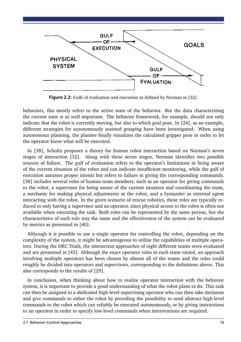
Figure 2.2: Gulfs of evaluation and execution as defined by Norman in [32].
behaviors, this mostly refers to the active state of the behavior. But the data characterizingthe current state is as well important. The behavior framework, for example, should not onlyindicate that the robot is currently moving, but also to which goal pose. In [24], as an example,different strategies for autonomously assisted grasping have been investigated. When usingautonomous planning, the planner finally visualizes the calculated gripper pose in order to letthe operator know what will be executed.
In [38], Scholtz proposes a theory for human robot interaction based on Norman’s sevenstages of interaction [32]. Along with these seven stages, Norman identifies two possiblesources of failure. The gulf of evaluation refers to the operator’s limitations in being awareof the current situation of the robot and can indicate insufficient monitoring, while the gulf ofexecution assumes proper intents but refers to failure in giving the corresponding commands.[38] includes several roles of human team members, such as an operator for giving commandsto the robot, a supervisor for being aware of the current situation and coordinating the team,a mechanic for making physical adjustments at the robot, and a bystander as external agentinteracting with the robot. In the given scenario of rescue robotics, these roles are typically re-duced to only having a supervisor and an operator, since physical access to the robot is often notavailable when executing the task. Both roles can be represented by the same person, but thecharacteristics of each role stay the same and the effectiveness of the system can be evaluatedby metrics as presented in [40].
Although it is possible to use a single operator for controlling the robot, depending on thecomplexity of the system, it might be advantageous to utilize the capabilities of multiple opera-tors. During the DRC Trials, the interaction approaches of eight different teams were evaluatedand are presented in [43]. Although the exact operator roles in each team varied, an approachinvolving multiple operators has been chosen by almost all of the teams and the roles couldroughly be divided into operators and supervisors, corresponding to the definitions above. Thisalso corresponds to the results of [29].
In conclusion, when thinking about how to realize operator interaction with the behaviorsystem, it is important to provide a good understanding of what the robot plans to do. This taskcan then be assigned to a dedicated high-level supervising operator who can then take decisionsand give commands to either the robot by providing the possibility to send abstract high-levelcommands to the robot which can reliably be executed autonomously, or by giving instructionsto an operator in order to specify low-level commands when interventions are required.
2.1 Behavior Control Approaches 13
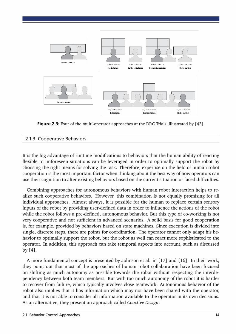
Figure 2.3: Four of the multi-operator approaches at the DRC Trials, illustrated by [43].
2.1.3 Cooperative Behaviors
It is the big advantage of runtime modifications to behaviors that the human ability of reactingflexible to unforeseen situations can be leveraged in order to optimally support the robot bychoosing the right means for solving the task. Therefore, expertise on the field of human robotcooperation is the most important factor when thinking about the best way of how operators canuse their cognition to alter existing behaviors based on the current situation or faced difficulties.
Combining approaches for autonomous behaviors with human robot interaction helps to re-alize such cooperative behaviors. However, this combination is not equally promising for allindividual approaches. Almost always, it is possible for the human to replace certain sensoryinputs of the robot by providing user-defined data in order to influence the actions of the robotwhile the robot follows a pre-defined, autonomous behavior. But this type of co-working is notvery cooperative and not sufficient in advanced scenarios. A solid basis for good cooperationis, for example, provided by behaviors based on state machines. Since execution is divided intosingle, discrete steps, there are points for coordination. The operator cannot only adapt his be-havior to optimally support the robot, but the robot as well can react more sophisticated to theoperator. In addition, this approach can take temporal aspects into account, such as discussedby [4].
A more fundamental concept is presented by Johnson et al. in [17] and [16]. In their work,they point out that most of the approaches of human robot collaboration have been focusedon shifting as much autonomy as possible towards the robot without respecting the interde-pendency between both team members. But with too much autonomy of the robot it is harderto recover from failure, which typically involves close teamwork. Autonomous behavior of therobot also implies that it has information which may not have been shared with the operator,and that it is not able to consider all information available to the operator in its own decisions.As an alternative, they present an approach called Coactive Design.
2.1 Behavior Control Approaches 14

This design approach not only shifts the focus towards the joint nature of cooperative tasks, italso adds the requirement of being able to provide feedback regarding the own actions insteadof just being able to perform them. In [19], Johnson summarizes this with the keywords ob-servability, predictability, and directability. Each of these aspects should be seen in an active anda passive way. Observability describes the capability of being able to observe the actions of theteam member as well as providing sufficient information to be observed as well. Predictabilityrefers to not only making observations, but also predictions regarding actions in the near future.Finally, directability refers to the ability of being able to give instructions as well as receivingthem.
In [39], Shah et al. present Chaski, the realization of a task-level executive. This is not onlyabout letting the robot decide which action it should take when working together with a hu-man, but also to consider which idle time of the human is caused by each action in order tominimize it, and thus improve overall task performance. This framework has been evaluated byconducting a user study where a human and a robot had to assemble three defined structureswith the robot able to support the human by collecting the next relevant parts. The results showthat, when being able to cooperate instead of being instructed step-by-step, not only the objec-tive task performance is increased, but also the perceived quality of teamwork is significantlyimproved.
Another existing approach for addressing cooperative behaviors is the Robot Task Commander(RTC) as presented in [14]. This framework combines scripts called process nodes with state
Figure 2.4: The system model of Coactive Design as proposed in [19].
2.1 Behavior Control Approaches 15
machines, and targets not only expert users to compose behaviors, but also non-experts byproviding a visual programming language for specifying the composition of state machines.For expert developers, a comprehensive integrated development environment (IDE) is offered.Behaviors are implemented in Python and communication between the user interface and therobot is done using ROS or ZeroMQ2. As stated in [34], RTC is part of the approach of teamNASA/JSC to the DARPA Robotics Challenge.
2.2 Behavior Verification
Verifying of defined behaviors is a very important aspect of making changes to a behavior duringruntime. Since practically testing of a specification before applying it to the robot is not possiblein this scenario since the robot is already in the field and thus not accessible, the operator needsto be sure that applied changes to a behavior do not lead to task failure because of insufficientspecification or even consistency issues.
As discussed by [12], there are several categories of verifying a robot behavior, such as logicalor temporal verification. But in general, two distinct aspects have to be taken into account.On the one hand, obviously, behavior verification has to ensure that the implemented behaviormeets the specification and executes exactly what is intended by the developer. On the otherhand, a meaningful verification algorithm also has to check if the specifications themselves areactually reasonable in order to achieve the desired goal of the behavior.
Extensive research has already been done regarding the first aspect, implementation verifica-tion. Given a specification model, for example in UML3 as covered by [21], software tools canreliably generate code out of it. A summary of available work on this topic is given by [11].Therefore, automatically generating code from a specification is not expected to be a problem,even if a custom implementation is required depending on the exact way of specifying and ex-ecuting a behavior. Using code generation for this step of realizing behaviors not only makes itmore efficient, but also guarantees that the implementation meets the specification.
The second aspect, however, targeting specification verification is far more complicated torealize. In order to be able to verify that a specification can achieve the desired goal, not only thespecification has to be modeled, but also the goal and relevant constraints. In addition, formallymodeling the goal typically involves reducing the goal to a certain domain, such as a pose orconfiguration to be reached. Modeling the goal in an abstract way, without already implicitlyinvolving the specification itself, is much more complicated. Furthermore, the constraints, whichneed to be considered in order to verify that they have been met, have multiple sources such asthe physical properties of the robot, but also the environment. Since the available data regardingmodeling these aspects of a task is typically very limited in the assumed scenarios relevant tothis thesis, comprehensive verification regarding the correctness of the specification itself is notapproached.
However, a partial verification of the behavior specification might be feasible. Reducing thedemand of making sure a specification is correct to the demand of making sure that a specifica-tion meets a set of defined criteria, makes it possible to provide at least some sanity checks, and2 http://zeromq.org/ (03/31/2015)3 http://www.uml.org/ (03/31/2015)
2.2 Behavior Verification 16
thus eliminate known, well-defined sources of common errors. A way to realize this approachis the definition of state constraints, as discussed in chapter 3.5.
2.2.1 Behavior Synthesis
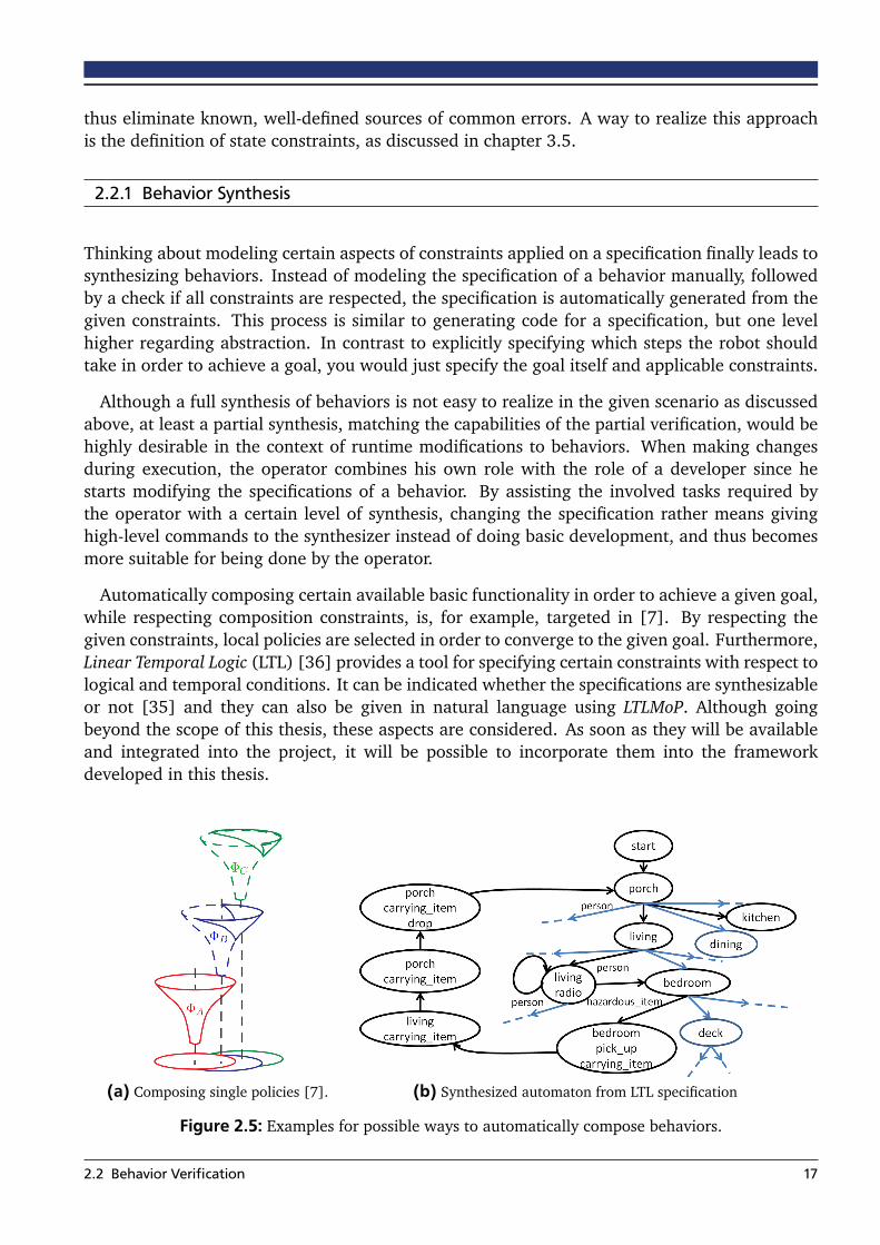
Thinking about modeling certain aspects of constraints applied on a specification finally leads tosynthesizing behaviors. Instead of modeling the specification of a behavior manually, followedby a check if all constraints are respected, the specification is automatically generated from thegiven constraints. This process is similar to generating code for a specification, but one levelhigher regarding abstraction. In contrast to explicitly specifying which steps the robot shouldtake in order to achieve a goal, you would just specify the goal itself and applicable constraints.
Although a full synthesis of behaviors is not easy to realize in the given scenario as discussedabove, at least a partial synthesis, matching the capabilities of the partial verification, would behighly desirable in the context of runtime modifications to behaviors. When making changesduring execution, the operator combines his own role with the role of a developer since hestarts modifying the specifications of a behavior. By assisting the involved tasks required bythe operator with a certain level of synthesis, changing the specification rather means givinghigh-level commands to the synthesizer instead of doing basic development, and thus becomesmore suitable for being done by the operator.
Automatically composing certain available basic functionality in order to achieve a given goal,while respecting composition constraints, is, for example, targeted in [7]. By respecting thegiven constraints, local policies are selected in order to converge to the given goal. Furthermore,Linear Temporal Logic (LTL) [36] provides a tool for specifying certain constraints with respect tological and temporal conditions. It can be indicated whether the specifications are synthesizableor not [35] and they can also be given in natural language using LTLMoP. Although goingbeyond the scope of this thesis, these aspects are considered. As soon as they will be availableand integrated into the project, it will be possible to incorporate them into the frameworkdeveloped in this thesis.
(a) Composing single policies [7]. (b) Synthesized automaton from LTL specification
Figure 2.5: Examples for possible ways to automatically compose behaviors.
2.2 Behavior Verification 17

2.3 Runtime Modifications
Runtime modifications can be achieved in basically two different ways. Each approach has itsown benefits which will be discussed in this section. One way is to directly modify the executedsource code while it is running. The capability of the used programming language to accountfor such on-the-fly modifications is the prerequisite for this solution. This is typically the case forscripting languages. In contrast, languages which need to be compiled before execution won’tbe applicable.
The other way is to specify behaviors by using an intermediate description language andparsing it for execution. Parsing can be done step-by-step whenever the next instruction or, inthe case of state machines, state is required. Therefore, the description can be modified in partswhich are currently not active, and these parts will be parsed later regardless of having changedsince the start of execution. However, this approach is not as flexible as the first one and impliessome limitations.
Since this thesis is meant to be integrated into a ROS-based project, implementation is prefer-ably done in either C++ or Python, the two programming languages natively supported byROS. Although there are attempts to enable a compilation-independent usage of C++ like theapproach described in [3], Python is an interpreted language and does not need to be compiled.Although the currently executed code itself cannot directly be modified, modules can easily beimported during runtime and, in the case of changes, reloaded again.
Appropriate choices for an intermediate description language (IDL) are for example markuplanguages like XML, YAML, or JSON. In such an approach, states are implemented in any pro-gramming language without requiring this language to enable runtime modifications itself. Thebehavior engine then parses an IDL description which refers to the single states and defineshow they are composed to form a high-level behavior. This approach of composing behaviors byusing XML as IDL is for example chosen in [28]. As stated above, modifications to the IDL filecould be made independently from parsing it for execution in order to achieve runtime modifi-cations. Thus, instead of parsing the IDL as a whole, the behavior engine in this case just usesthe IDL specification to look up the next state when the current one has finished. This is a veryflexible way of modifying the behavior, but it also comes along with some problems.
For using an IDL this way, it is an implicitly defined prerequisite that the set of state imple-mentations is fixed and the states itself are only functional. Each transition execution includesinstantiating a new object which means that states are limited in their functionality in a waythat, for example, the properties of a state object have to be constant. Nonetheless, instantiationduring runtime is an additional source of error. Finally, it is the most significant problem of thisapproach that behaviors cannot be verified regarding consistency when parsing them on-the-fly.
In contrast, specifying behaviors as Python module is not only an approach which can benefitfrom the amount of available libraries and the flexibility of Python. It also enables to instantiateall states required during the execution of a behavior when it is started, since the state machinespecification is part of the class description.
2.3 Runtime Modifications 18

2.4 Existing Behavior Frameworks
After having discussed the most relevant approaches in general, this section will now focus onselected work which comes into consideration as a foundation for the approach developed inthis thesis. This implies certain demands on the existing frameworks, derived from the conceptsdiscussed in the previous sections of this chapter.
Since the main contribution of this thesis is the ability to modify currently executed behaviors,being able to extend the regarding framework by one of the two ways discussed in section 2.3is an important criterion. This means that implementation has to be possible by either using ascripting language like Python, or by providing behavior definition in an intermediate formatsuch as XML. For the reasons discussed in this section, it is favorable to not need to rely onan intermediate description language in order to improve robustness and provide flexibility fordeveloping single states. However, both approaches are possible and if the framework offersfunctionality for addressing these issues, it is also a valid choice.
Its provided degree of operator interaction is another relevant factor for choosing the rightframework as basis. Ideally, the framework already provides means to monitor the currentstate of execution at a remote operating station, and allows for adjustments by the operatorinfluencing runtime parameters or at least pausing behavior execution at certain points in time.Pausing execution is a helpful prerequisite for modifying behavior during runtime because itallows to ensure consistency of changes. On the other hand, changing the behavior should notprevent the robot from taking actions in the meantime. This is discussed in detail in chapter3.3.
In addition to the mentioned requirements, there are some advantageous aspects a chosenapproach may support in order to facilitate development of advanced features. These aspectsmostly result from the fact that behaviors will be modified during runtime which requires effi-cient and intuitive specification of behaviors. Furthermore, the behaviors have to be robust inorder to prevent failure during execution. For this reason, the framework ideally incorporatesconsistency checks and some sort of behavior verification. An appropriate user interface wouldalso be a plus. Last but not least, it must be possible to integrate the system into the rest of theproject by relying on ROS.
2.4.1 XABSL
Providing a high-level specification language for robot agent behaviors is the goal of XABSL.It has been developed by Lötzsch et al. in context of the RoboCup as described in [42] andextended in [9]. Behaviors can be specified by composing basic behaviors, referring to simpleactions, and behavior modules called options. Options can refer to other options and thus forma hierarchy, the so-called option graph. Internally, options are modeled as state machines whereeach state contains a decision tree to determine the next transition.
XABSL relies on XML as an intermediate description language. Although initially develop-ment has been done by writing the XML description manually, XABSL has been extended to use
2.4 Existing Behavior Frameworks 19
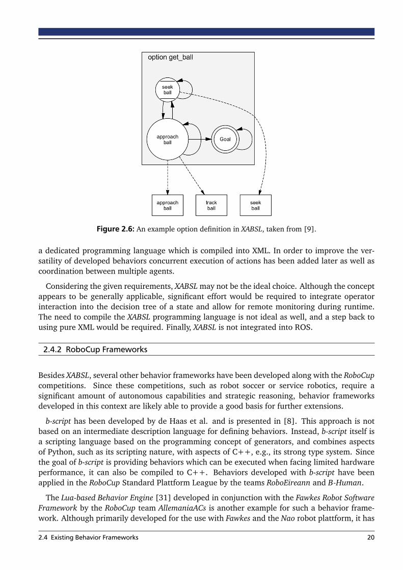
Figure 2.6: An example option definition in XABSL, taken from [9].
a dedicated programming language which is compiled into XML. In order to improve the ver-satility of developed behaviors concurrent execution of actions has been added later as well ascoordination between multiple agents.
Considering the given requirements, XABSL may not be the ideal choice. Although the conceptappears to be generally applicable, significant effort would be required to integrate operatorinteraction into the decision tree of a state and allow for remote monitoring during runtime.The need to compile the XABSL programming language is not ideal as well, and a step back tousing pure XML would be required. Finally, XABSL is not integrated into ROS.
2.4.2 RoboCup Frameworks
Besides XABSL, several other behavior frameworks have been developed along with the RoboCupcompetitions. Since these competitions, such as robot soccer or service robotics, require asignificant amount of autonomous capabilities and strategic reasoning, behavior frameworksdeveloped in this context are likely able to provide a good basis for further extensions.
b-script has been developed by de Haas et al. and is presented in [8]. This approach is notbased on an intermediate description language for defining behaviors. Instead, b-script itself isa scripting language based on the programming concept of generators, and combines aspectsof Python, such as its scripting nature, with aspects of C++, e.g., its strong type system. Sincethe goal of b-script is providing behaviors which can be executed when facing limited hardwareperformance, it can also be compiled to C++. Behaviors developed with b-script have beenapplied in the RoboCup Standard Plattform League by the teams RoboEireann and B-Human.
The Lua-based Behavior Engine [31] developed in conjunction with the Fawkes Robot SoftwareFramework by the RoboCup team AllemaniaACs is another example for such a behavior frame-work. Although primarily developed for the use with Fawkes and the Nao robot plattform, it has
2.4 Existing Behavior Frameworks 20
been ported to ROS later and is based on the lightweight scripting language Lua. This engineassumes three behavior levels, namely Control Loops, Skills, and Agent. Using this behavior en-gine, skills can be defined in order to incorporate basic robot capabilities. An external behaviorexecutive is then required to compose and execute these defined skills.
Although these frameworks provide good ways for defining autonomous behaviors and es-pecially multi-agent interaction, they are hardly applicable for scenarios such as disaster mit-igation. One important problem is the limited incorporation of operator involvement duringruntime, mainly supporting passive monitoring for debugging, but no cooperation in order tofulfill a task. Furthermore, their main application are robots with very limited hardware re-sources, operating in a well-defined and structured environment, such as a soccer field. Thisis very different from what this thesis is targeting, impeding to utilize some of the underlyingconcepts of these behavior frameworks.
2.4.3 SMACH
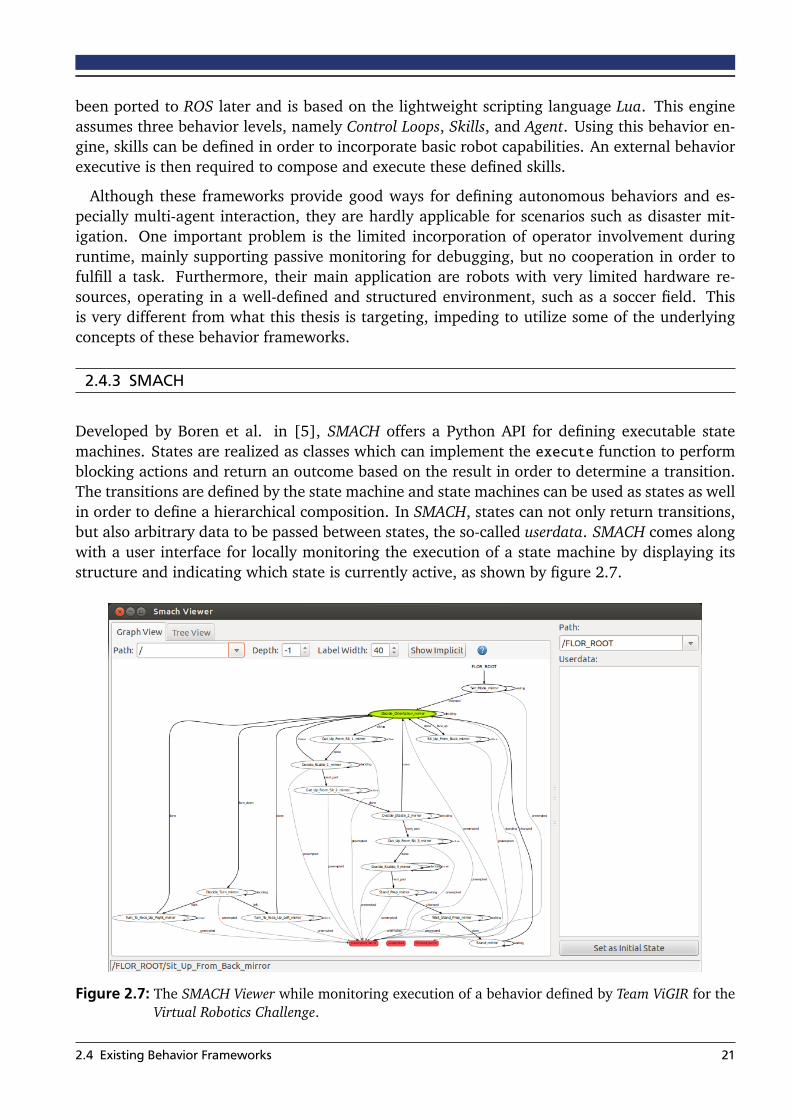
Developed by Boren et al. in [5], SMACH offers a Python API for defining executable statemachines. States are realized as classes which can implement the execute function to performblocking actions and return an outcome based on the result in order to determine a transition.The transitions are defined by the state machine and state machines can be used as states as wellin order to define a hierarchical composition. In SMACH, states can not only return transitions,but also arbitrary data to be passed between states, the so-called userdata. SMACH comes alongwith a user interface for locally monitoring the execution of a state machine by displaying itsstructure and indicating which state is currently active, as shown by figure 2.7.
Figure 2.7: The SMACH Viewer while monitoring execution of a behavior defined by Team ViGIR for theVirtual Robotics Challenge.
2.4 Existing Behavior Frameworks 21

Although being a standalone library in its core, SMACH is integrated into ROS and works wellin this combination for coordination between external ROS nodes. It has proven its applicabilityin several projects along with the PR24 and other robots and is for example combined with adecision making tool in [13].
In general, SMACH is applicable as basis for the behavior framework since it is easily extensibleand well integrated into ROS and Python. It also offers a basic form for monitoring the executionof a state machine. However, it does not incorporate the operator into its concept and thus needsto be extended with cooperation principles and the ability to give user commands to behaviors.
2.4.4 Flor Behavior Engine
The Flor Behavior Engine (FlorBE) is a previous work of the author of this thesis. It has beendeveloped in the context of Team ViGIR’s previous participation at the DARPA Robotics Challengeand is presented in [37]. Main goal of this behavior engine is to better integrate the operatorinto behaviors, allowing for cooperative approaches to tasks and compensation of missing au-tonomous capabilities of the robot, while taking as much workload as possible away from theoperator considering the respective scenario.
FlorBE is based on SMACH to utilize its flexibility and extends several aspects, mainly regard-ing communication with a remote operator. For this reason, it comes along with a very simpleuser interface for triggering transitions and displaying transition intents of the behavior to theoperator. This user interface is intended to be integrated into an existing system for monitoringthe physical and internal state of the robot, but based upon the existing communication protocolbetween robot and operator, a more advanced user interface can be added.
The introduction of a coordination mechanism, the Autonomy Level is a further extension toSMACH. This mechanism helps the operator to flexibly reduce the autonomy of the robot and
Full
High
Low
OffOff
Deg
ree
of a
uton
omy
Autonomy Level: Example Decision:
Wait for operator input
Target Position reached
Detect when fallen
Internal parameter changed
Planning failed
Figure 2.8: Example actions of different Autonomy Levels as defined in [37].
4 https://www.willowgarage.com/pages/pr2/overview (03/31/2015)
2.4 Existing Behavior Frameworks 22
thus prevents it from making decisions on its own. As a result, behaviors are able to deal withchanging uncertainty in scenarios while using the same state machine for implementation of theactions to be taken.
This combination of SMACH and approaches for coordination between operator and robot isa good basis to build upon. For this reason, more details regarding FlorBE are given in chapter4.1. However, behavior development is very tedious when implementing complex behaviors andespecially when defining the transitions between states the current way is prone to consistencyerrors. Therefore, improving the development process to a level at which behaviors can easilyand safely be defined while executing a task will be a very important extension to FlorBE. Fur-thermore, the capabilities of Python will be used for importing behaviors during runtime andthus for being more flexible regarding custom behavior changes.
2.4 Existing Behavior Frameworks 23
3 Concepts
The onboard behavior engine part of the approach developed in this thesis builds upon previouswork of the author, and therefore extends FlorBE which has been briefly described in the previ-ous section and will be discussed in detail in chapter 4.1. This chapter discusses the availablebasis and required extensions in a formal way to provide a basis for implementation and furtherdevelopment. Additionally, the requirements of the given scenario, which have been presentedin chapter 1.1, are taken into consideration by the concepts of this chapter.
Most of the concepts presented in sections 3.1 and 4.1.2 are based on the existing imple-mentations of SMACH and FlorBE. However, they are summarized in a formal way and havebeen extended to support the newly added concepts. Also, providing arbitrary data has been aproblem in FlorBE and section 3.2.2 provides a concept for solving this issue.
Subsequently, section 3.3 presents the overall concept of runtime modifications to behaviorsand discusses aspects such as consistency. Further, Section 3.4 targets on how to assist devel-opment of behaviors and to specify changes, providing a basis for the newly developed userinterface. Finally, section 3.5 discusses a formal approach on guaranteeing successful behaviorexecution already when defining a specification by introducing state constraints.
3.1 Definitions
In order to enable discussion of the underlying concepts of this thesis, it is important to exactlydefine the used terms and relate them to each other. The goal of this thesis is the developmentof a flexible high-level behavior engine, thus we assume that the basic capabilities of the robotare already available and provided externally.
Definition: Primitive. A primitive p ∈ P is any atomic capability of the robot which converts aset of input data Di into a set of output data Do in order to fulfill a specified goal Gp.
These primitives, in general referenced as actions, are typically not instantaneous and side-effects may change the physical state of the robot such as moving its joints. For example, therecan be a grasping primitive which provides a way to close the fingers of the robot. Input datacan be a specification of how much the fingers should be closed or maybe which force should beapplied to the grasped object. The output data then can indicate the sensed force to the fingersand the closing state. A second example for a primitive is a state which plans a certain motion,getting a target endeffector pose as input and generating a joint configuration which can beused for reaching this pose. This primitive would have no side-effects since it only plans themotion, but does not execute it. A third primitive could then provide a way to execute a certainjoint configuration.
Execution of a primitive can fail which means that a subset of the output data doesn’t meetthe goal specification. Related to the example of motion planning, this could mean that the
24

specified target pose is not reachable. Primitives are not explicitly defined for behaviors and canbe provided in any format. Thus, for making them usable to behaviors, there is a way requiredfor interfacing them.
Definition: State. A state s ∈ S interfaces functionality with behaviors, where the set of allstate implementations S includes states based on primitives Sp ⊆ S. Each state defines outcomes sOcand execution of a state is terminated by returning one outcome matching the result of executionoc ∈ sOc.
States based on primitives form the majority of all types of states. They evaluate the datareturned by their respective primitive in order to decide about which outcome to trigger. Forthis purpose, each sp ∈ Sp defines an evaluation function e : DO −→ sOc which maps the outputdata of its primitive to one of the declared outcomes of the state. Assuming for example thegrasping primitive described above, a grasping state could specify three outcomes: grasped,failed_to_close, failed_to_grasp. The outcome grasped is only returned if the fingers are actuallyclosed and a force to the finger sensors indicates that the object is inside. It would returnfailed_to_close if it is unable to close the fingers and failed_to_grasp if the fingers are closed, butthere is no object inside.
In special cases, states can also invoke multiple primitives and combine their single results,but in favor of simplicity and modularity, this is a rather exceptional case. Besides referring toa primitive, states can also be implemented in an arbitrary way depending on the purpose theyshould provide to their containing state machine.
Definition: State Machine. A state machine SM composes a set of states SSM where each states(i) ∈ SSM is the instantiation of a state implementation s ∈ S. When a state returns a specificoutcome oc(i) ∈ s(i)Oc, the transition function tSM : SSM , sOc −→ SSM ∪ SMOc defines which state isexecuted next.
The transition function tSM assigns each pair of a state and one of its outcomes (s(i), oc(i))to its successor. This successor can either be the next state to be executed s(i+1), or one of theoutcomes oc(SM) ∈ SMOc of the state machine itself which means that finishing execution of thisstate will also finish execution of the whole state machine.
State machines are states themselves and thus provide a way for representing hierarchicalstate machines. The purpose of a state machine is to define the control flow of a behavior,i.e. the sequence in which states are executed depending on their result, using the specifiedtransition function.
In addition to the control flow, states need a way to pass data to each other. For example,there can be a state which provides perception data by using an object recognition primitiveand returns a pose of interest. Another state may now plan footsteps to a target pose for lettingthe robot walk and thus needs a way to get the pose generated by the perception state.
Definition: Userdata. Each state machine SM defines userdata DSM , represented by a set ofkey-value pairs where f : KD,SM −→ VD,SM maps each specific key k ∈ KD,SM to its respective value.States define userdata keys they need, sI , and provide, sO.
3.1 Definitions 25

Passing data from state A to state B with s(A), s(B) ∈ SSM is thus defined as f (kI ,sB) | kI ,sB = kO,sA
where kI ,sB ∈ s(B)I is an input key of s(B) and kO,sA ∈ s(A)O is an output key of s(A).
Using the concept of userdata as provided by SMACH [5] gives an easy and flexible way ofpassing arbitrary data between states. As mentioned above, there can be one state for generatinga certain joint trajectory and a second state for executing any joint trajectory. The concept ofuserdata allows the planning state to specify an output key for holding the generated trajectoryafter the state has finished execution and the executing state to specify an input key for providingthe joint trajectory to be executed. This not only allows for easy combination of these two states,but this one execution state can also be used along with any other state which generates a jointtrajectory or even accept manually defined trajectories.
Definition: Behavior. A behavior B is implemented by its state machine BSM . Furthermore,each behavior defines a set of parameters BP where each p ∈ BP is chosen when starting a behavior.Behaviors can be used as states of other behaviors.
Figure 3.1: Composition diagram of the concepts presented in this section, tSM is implicitly defined bythe solid arrows inside BSM . In this example, s1 is a state implementation based on theprimitive p1 and may execute an action generating data while s2 performs branching basedon its input data.
3.1 Definitions 26

While the implementation of a behavior is given by its state machine, the interface of a behav-ior is defined by its behavior manifest. The manifest contains meta information such as the nameof the behavior and the author, but also important interface specifications e.g., which other be-havior is included in this one. Including a behavior into another means the included behavior isinstantiated along with all the states of the outer behavior’s state machine and embedded intothis state machine as one of the states. This enables the creation of behaviors in certain layers ofabstraction. Some lower level behaviors, for example, may be constructed by combining only afew states based on primitives and then being composed by a complex task-level behavior. Thenumber of layers of abstraction depends on the complexity of available primitives as well as ofthe tasks to be solved.
A concept introduced by the Flor Behavior Engine in [37] is the Autonomy Level. It regulatesthe control flow of a state machine by stopping certain transitions when the operator declaresthat they are not reliable enough with respect to the current situation.
Definition: Autonomy Level. In a state machine SM , each outcome of a state oc(i) ∈ s(i)Ocdefines a minimum autonomy level a(i)oc which will block the corresponding transition toc,i :=tSM(s(i), oc(i)). During execution, the current autonomy level is determined by aSM , thus onlyallowing the execution of toc,i | a(i)oc < aSM .
All transitions which are not allowed to be triggered autonomously are suggested to the op-erator and require explicit manual confirmation to be executed. This mechanism ensures thattransitions are only executed when their required outcome is reliably detectable. The AutonomyLevel aSM can be changed at any time during behavior execution, enabling a way of small ad-justments regarding the control flow of the behavior. However, the changes are very limited andin order to provide the flexibility required by the scenarios described in chapter 1.1, additionalways of making changes to a behavior need to be added.
3.2 Operator Interaction
In order to facilitate a close teamwork between robot and operator, the behavior frameworksupports a built-in interaction protocol. Following this protocol, a running behavior can bemonitored and several commands can influence execution of the behavior. Basic monitoringof the current state is supported by the Behavior Mirror, a concept targeting at robustness andreduction of required bandwidth, which will be explained later in this section.
Based on the previously defined Autonomy Level, the behavior will not always be allowed toactually trigger its desired outcome. In this case, the operator should be notified that a certaintransition may be ready to be taken. Afterwards, it is up to the operator to verify or falsify thissuggestion. In order to reduce bandwidth usage and prevent redundant messages, all suggestedoutcomes oc(i) are added to a set Ri of sent requests. Thus, a request is only sent if oc(i) /∈ Ri.
While rejecting a suggested outcome is easily achieved by ignoring the respective suggestion,verifying it needs a command for triggering an outcome. Actually, the taken approach does notdistinguish between outcomes triggered as a reaction on a suggestion or triggered on purpose
3.2 Operator Interaction 27
of the operator. However, when the operator commands a certain outcome, the currently activestate is forced to return this specified outcome regardless of the result of its own evaluationfunction.
In addition to its regular outcomes, each state instantiation has a special implicit outcomeoc(i)p ∈ s(i)Oc. The purpose of this outcome is to preempt the current execution and to offer theoperator the possibility to completely stop a behavior at any point in time. For this reason,the outcome oc(i)p of any state inside a state machine s(i) ∈ SSM fulfills the following condi-
tion: tSM(s(i), oc(i)p ) = ocSMp . This means, a preempting outcome is always propagated to the
hierarchy’s root and thus causes the whole behavior to be preempted, not only the current state.
Another command available to the operator is locking a behavior in its currently active state.This command is newly added and has not been available in FlorBE. If a behavior is locked ina certain state, it means that this state will still be executed in the usual way. But in case thestate would return any outcome, this outcome is temporarily stored, but not returned. This isexpressed by the following condition: ∀oc(i) ∈ s(i)Oc,l : tSM ,l(s
(i)l , oc(i)) := s(i)l where the subscript
l indicates that the referred state is locked. The regular transition function tSM is temporarilyreplaced by a special transition function for locking tSM ,l . After a state has been unlocked again,it will return its stored outcome, if any.
3.2.1 Behavior Mirror
The Behavior Mirror allows for easy and efficient monitoring of the current state of executionof any active behavior. It is supposed to mirror the remotely running state machine in order toprovide a local, easily accessible representation. All tools which require access to the behavior inorder to monitor its execution, can instead use the Behavior Mirror. Since a mirrored behavior isintended to completely remove the need for further remote behavior access, the Behavior Mirrorhas to make sure the mirrored behavior correctly reflects the actual behavior’s structure at anytime.
Definition: Mirrored Behavior. A behavior Bm is called a mirrored behavior of B whenever thestructure of its state machine BSM ,m is isomorphic to BSM and s(i)a,m ∈ SSM ,m is determined by ϕ(s(i)a ),where ϕ is the isomorphic transformation ϕ : SSM −→ SSM ,m.
Note that ϕ is bijective, meaning that it is always possible to know s(i)a when having accessto s(i)a,m. Furthermore, the definition does not include any requirements regarding the actualfunctionality of a state, meaning the state implementation of s(i) and its mirrored counterparts(i)m may differ. This is a rather essential requirement since it is not desirable to actually execute abehavior in order to mirror it. Instead, the Behavior Mirror provides a separate implementationfor mirrored states which does not execute anything state-specific and just updates monitoringinformation.
This concept enables to have minimal updates regarding mirror synchronization while alwaysknowing the currently active state of the remote behavior. Prerequisite is a once synchronized
3.2 Operator Interaction 28
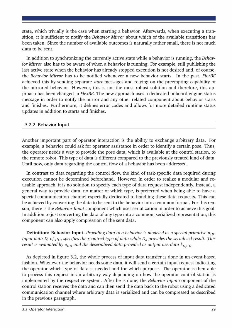
state, which trivially is the case when starting a behavior. Afterwards, when executing a tran-sition, it is sufficient to notify the Behavior Mirror about which of the available transitions hasbeen taken. Since the number of available outcomes is naturally rather small, there is not muchdata to be sent.
In addition to synchronizing the currently active state while a behavior is running, the Behav-ior Mirror also has to be aware of when a behavior is running. For example, still publishing thelast active state when the behavior has already stopped execution is not desired and, of course,the Behavior Mirror has to be notified whenever a new behavior starts. In the past, FlorBEachieved this by sending separate start messages and relying on the preempting capability ofthe mirrored behavior. However, this is not the most robust solution and therefore, this ap-proach has been changed in FlexBE. The new approach uses a dedicated onboard engine statusmessage in order to notify the mirror and any other related component about behavior startsand finishes. Furthermore, it defines error codes and allows for more detailed runtime statusupdates in addition to starts and finishes.
3.2.2 Behavior Input
Another important part of operator interaction is the ability to exchange arbitrary data. Forexample, a behavior could ask for operator assistance in order to identify a certain pose. Thus,the operator needs a way to provide the pose data, which is available at the control station, tothe remote robot. This type of data is different compared to the previously treated kind of data.Until now, only data regarding the control flow of a behavior has been addressed.
In contrast to data regarding the control flow, the kind of task-specific data required duringexecution cannot be determined beforehand. However, in order to realize a modular and re-usable approach, it is no solution to specify each type of data request independently. Instead, ageneral way to provide data, no matter of which type, is preferred when being able to have aspecial communication channel especially dedicated to handling these data requests. This canbe achieved by converting the data to be sent to the behavior into a common format. For this rea-son, there is the Behavior Input component which uses serialization in order to achieve this goal.In addition to just converting the data of any type into a common, serialized representation, thiscomponent can also apply compression of the sent data.
Definition: Behavior Input. Providing data to a behavior is modeled as a special primitive pI D.Input data Di of pI D specifies the required type of data while Do provides the serialized result. Thisresult is evaluated by esI D and the deserialized data provided as output userdata kO,sI D.
As depicted in figure 3.2, the whole process of input data transfer is done in an event-basedfashion. Whenever the behavior needs some data, it will send a certain input request indicatingthe operator which type of data is needed and for which purpose. The operator is then ableto process this request in an arbitrary way depending on how the operator control station isimplemented by the respective system. After he is done, the Behavior Input component of thecontrol station receives the data and can then send the data back to the robot using a dedicatedcommunication channel where arbitrary data is serialized and can be compressed as describedin the previous paragraph.
3.2 Operator Interaction 29
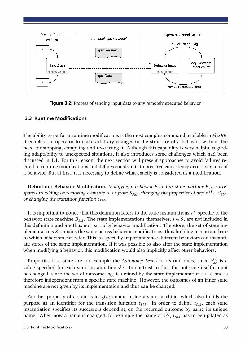
Figure 3.2: Process of sending input data to any remotely executed behavior.
3.3 Runtime Modifications
The ability to perform runtime modifications is the most complex command available in FlexBE.It enables the operator to make arbitrary changes to the structure of a behavior without theneed for stopping, compiling and re-starting it. Although this capability is very helpful regard-ing adaptability to unexpected situations, it also introduces some challenges which had beendiscussed in 1.1. For this reason, the next section will present approaches to avoid failures re-lated to runtime modifications and defines constraints to preserve consistency across versions ofa behavior. But at first, it is necessary to define what exactly is considered as a modification.
Definition: Behavior Modification. Modifying a behavior B and its state machine BSM corre-sponds to adding or removing elements to or from SSM , changing the properties of any s(i) ∈ SSM ,or changing the transition function tSM .
It is important to notice that this definition refers to the state instantiations s(i) specific to thebehavior state machine BSM . The state implementations themselves, s ∈ S, are not included inthis definition and are thus not part of a behavior modification. Therefore, the set of state im-plementations S remains the same across behavior modifications, thus building a constant baseto which behaviors can refer. This is especially important since different behaviors can instanti-ate states of the same implementation. If it was possible to also alter the state implementationwhen modifying a behavior, this modification would also implicitly affect other behaviors.
Properties of a state are for example the Autonomy Levels of its outcomes, since a(i)oc is avalue specified for each state instantiation s(i). In contrast to this, the outcome itself cannotbe changed, since the set of outcomes sOc is defined by the state implementation s ∈ S and istherefore independent from a specific state machine. However, the outcomes of an inner statemachine are not given by its implementation and thus can be changed.
Another property of a state is its given name inside a state machine, which also fulfills thepurpose as an identifier for the transition function tSM . In order to define tSM , each stateinstantiation specifies its successors depending on the returned outcome by using its uniquename. When now a name is changed, for example the name of s(i), tSM has to be updated as
3.3 Runtime Modifications 30
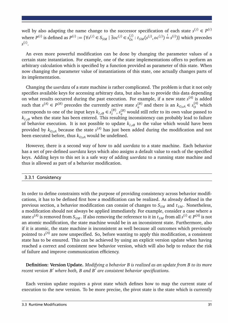
well by also adapting the name change to the successor specification of each state s( j) ∈ P(i)
where P(i) is defined as P(i) := {∀s( j) ∈ SSM | ∃oc( j) ∈ s( j)Oc : tSM(s( j), oc( j))!= s(i))} which precedes
s(i).
An even more powerful modification can be done by changing the parameter values of acertain state instantiation. For example, one of the state implementations offers to perform anarbitrary calculation which is specified by a function provided as parameter of this state. Whennow changing the parameter value of instantiations of this state, one actually changes parts ofits implementation.
Changing the userdata of a state machine is rather complicated. The problem is that it not onlyspecifies available keys for accessing arbitrary data, but also has to provide this data dependingon what results occurred during the past execution. For example, if a new state s(A) is addedsuch that s(A) ∈ P(B) precedes the currently active state s(B)a and there is an kO,sA ∈ s(A)O whichcorresponds to one of the input keys kI ,sB ∈ s(B)I , s(B)a would still refer to its own value passed tokI ,sB when the state has been entered. This resulting inconsistency can probably lead to failureof behavior execution. It is not possible to update kI ,sB to the value which would have beenprovided by kO,sA because the state s(A) has just been added during the modification and notbeen executed before, thus kO,sA would be undefined.
However, there is a second way of how to add userdata to a state machine. Each behaviorhas a set of pre-defined userdata keys which also assigns a default value to each of the specifiedkeys. Adding keys to this set is a safe way of adding userdata to a running state machine andthus is allowed as part of a behavior modification.
3.3.1 Consistency
In order to define constraints with the purpose of providing consistency across behavior modifi-cations, it has to be defined first how a modification can be realized. As already defined in theprevious section, a behavior modification can consist of changes to SSM and tSM . Nonetheless,a modification should not always be applied immediately. For example, consider a case where astate s(A) is removed from SSM . If also removing the reference to it in tSM from all s(i) ∈ P(A) is notan atomic modification, the state machine would be in an inconsistent state. Furthermore, alsoif it is atomic, the state machine is inconsistent as well because all outcomes which previouslypointed to s(A) are now unspecified. So, before wanting to apply this modification, a consistentstate has to be ensured. This can be achieved by using an explicit version update when havingreached a correct and consistent new behavior version, which will also help to reduce the riskof failure and improve communication efficiency.
Definition: Version Update. Modifying a behavior B is realized as an update from B to its morerecent version B′ where both, B and B′ are consistent behavior specifications.
Each version update requires a pivot state which defines how to map the current state ofexecution to the new version. To be more precise, the pivot state is the state which is currently
3.3 Runtime Modifications 31

active before performing the behavior update and is supposed to be still active when the updatehas finished.
Definition: Pivot State. When performing a version update, exactly one state s(i)a = s(i)piv is called
the pivot state of this particular update. s(i)piv is immutable during the update and has to be elementof SSM ∪ SSM ′.
In order to provide consistency, the pivot state has to be locked during the whole processof behavior modification: s(i)piv ⇒ s(i)l . This ensures that the pivot state stays active during theupdate process. Furthermore, locking the pivot state before actually starting to modify thebehavior ensures the required immutability during the modifications. Since state machinesare also states themselves, the pivot state can be a state machine as well. In this case, theimmutability requirement implies that the inner state machine of the pivot state remains thesame which means that no type of change is allowed to any of the inner states or the innertransition function.
If the behavior would not be locked during a modification, the active state is likely to changein the meantime because specifying the desired modifications requires some time. Even if theamount of required time is very small and the expected execution time of the action requestedby the active state is sufficiently high, events might always occur which can trigger a transitionby letting the state return one of its outcomes oc(i). This means the onboard behavior wouldtransition to a different state s(i+1)
a := tSM(s(i), oc(i)). Propagating this transition to the versioncurrently being modified by the operator is not possible, since it is not guaranteed that stills(i+1) ∈ SSM because this state could have been deleted along with the modifications made to
Figure 3.3: Example version update where the active state, s(3)piv , has to stay active and unchanged duringthe whole process. However, the targets of its transitions can be changed.
3.3 Runtime Modifications 32

the behavior. As a result, this would violate the condition that the pivot state stays active duringa version update, as required by the definition of the pivot state, because s(i)piv 6= s(i+1)
a . For thisreason, behavior modifications are only possible if a behavior is locked. This also ensures thatthe robot executes no unexpected actions while the operator might be distracted by modifyingthe behavior, as already discussed in chapter 1.1.
3.3.2 Behavior Update
When commanding a behavior version update, the operator needs a way to either send the newbehavior version or send an indication of all modifications which can then be applied to thealready known and running version to construct the new one. In order to keep the requiredamount of data low, it is favorable to just send a minimal summary of applied modificationsinstead of the whole new version, since the part of which a behavior changes is typically muchless than the part which stays the same. This minimal summary of modifications is called patchand applying a patch to the appropriate previous version of a behavior will create a new behaviorcontaining exactly the changes for which the patch has been created.
Definition: Behavior Patch. ∆ is a function in the behavior space and called the patch of aversion update B −→ B′ if it fulfills the condition ∆B→B′(B) = B′.
Besides transmitting minimal data by relying on ∆B→B′ instead of B′, given the case that B isknown to the onboard engine, it is also important that performing a behavior modification doesnot negatively affect task performance. Although the approach of how to perform a behaviorupdate cannot guarantee that the execution of B′ itself is not a source of failure, which istargeted in the next section, it has to ensure that the progress of switching from B to B′ isonly taking place when it will be successful. This involves a number of verification checksreferring to the properties discussed in the previous section regarding consistency.
In summary, the workflow of performing a behavior update includes several steps, while it isan important aspect of these steps that they happen in parallel to the execution of the old behav-ior and, if the behavior update fails, the old behavior can keep executing without interruption.So, as a first step, B′ has to be generated from ∆B→B′ and the condition ∆B→B′(B) = B′ has tobe verified. Afterwards, it has to be verified that B′ itself is a consistent behavior and that themodifications are according the definition in section 3.3. Finally, the pivot state s(i)piv has to bedetermined and the conditions discussed in 3.3.1 have to be checked. Only if all of these stepshave been successful, B is interrupted and substituted by B′.
3.4 Behavior Development
The process of development is an important factor when designing the behavior framework, butit is even more crucial when speaking of runtime modifications. When making modifications toan executed behavior, parts of the development process are mixed with execution. This has tobe taken into account at a very early stage of designing the concept of the system because someof the design goals are opposed. For example, while controlling a behavior at runtime requires
3.4 Behavior Development 33

focus on the current state of execution, behavior development requires a complete overviewover the whole structure of the state machine, regardless of the currently active state.
For this reason, two different views on a behavior are provided to the operator by the userinterface. One view is focused on the currently active state and augmented with recent feed-back of the executed behavior. It also provides an interface for sending the above mentionedcommands to the behavior. The second view displays the whole state machine and enablesmodification of its structure and of the properties of each state. During execution, modificationis not allowed if the above mentioned consistency requirements are not fulfilled. However, thisview can always be used for getting an overview.
One implication of runtime modification is that in most of the cases, the operator also hasto fulfill the role of a developer. Ideally, during execution, there is a person available who hasexperience with developing behaviors so that this person can take the part of implementing thedesired changes. But this should not be required and thus development of behaviors or changesmust be very easy. Furthermore, in order to avoid errors and to be efficient, since time is a criticalfactor during task execution, the development process has to be aided and automated as muchas possible while still providing a high level of flexibility and allowing custom modifications.
In order to provide this required way of easy development, the user interface allows for model-ing state machines and setting the properties of each state. On saving, source code is generatedfor whole model which can then be executed by the behavior engine based on FlorBE andSMACH. In addition, manual extensions of the generated code can be made and enable greatflexibility for behavior development, especially when the development takes place before exe-cution.
Required robustness regarding specification errors is another important aspect of modifyingbehaviors during execution. It is not sufficient to only have a behavior executive which can han-dle failure of a behavior without further negative consequences. The development of behaviormodifications has to take into account possible sources of errors as well and to offer functionalityfor detecting and correcting them. Thus, a consistency check of a whole behavior is performedat least before it is saved, and partial checks, such as the validity of given parameter values, areperformed as soon as possible.
3.5 State Constraints
Constraining state execution is a very helpful mechanism for making sure that a state is lessprone to failure during its execution. Conditions, such as having certain data available or beingin a stable pose for manipulation, can make sure that the prerequisites for primitives used bya state are fulfilled. In order to specify such conditions, each state implementation defines anindividual set of preconditions, depending on the primitives it refers to or the functionality itoffers.
Definition: Precondition. Each state implementation defines a set of preconditions sΦ. In orderto enter a state s(i) ∈ SSM during execution, each precondition φ ∈ s(i)Φ has to evaluate to true.φ : Σ −→ {true,false} is a function applied to the current situation of the robot σ.
3.5 State Constraints 34

In addition to the conditions under which a state can be executed, state constraints can beused as well in order to guarantee certain properties when a state finishes its execution. Thisextends the conditions required to be fulfilled for returning a specific outcome in a way thatbetter takes into account the meaning expressed by the conditions instead of just checkingspecific values. Referring again to the example of grasping an object by closing the fingers ofthe robot, the conditions for triggering the outcome that indicates success consist of checkingthe value of how much the fingers are closed and which force is applied to the sensors. Thisis very specific to the way grasping is implemented. When using a different approach, such asa pneumatic gripper, in a second state, these conditions may be different, but their meaning isstill the same. This meaning can be expressed using postconditions, stating that the object ofinterest is now attached to the hand, which is the same for both states.
Definition: Postcondition. Each state implementation defines a set of postconditions sΨ,Oc. Onreturning one of its outcomes oc(i) ∈ s(i)Oc, a state has to ensure that each postcondition ψoc ∈ s(i)Ψ,Occorresponding to the respective outcome is fulfilled. ψoc is a function with the same properties asφ.
Based on these two definitions, a critical factor for being able to make use of the conditions isto find a way how to represent the current situation of the robot σ. σ needs to be representedin an abstract way, applicable for all different types of states and building a common basis towhich states can refer. This includes choosing a suitable level of abstraction as well as having away to measure the current value of each property included in σ. One way to get these values isrelying on postconditions, since they define in which situation, regarding some properties, therobot is after returning a specific outcome. But these properties of the robot are only a subset ofσ and may also, obviously, not only be defined by states, but by external events as well.
Although a complete definition of σ is not yet available, it can already be defined partially.One aspect taken into consideration when verifying the composition of states is availability ofuserdata. Defining the input keys s(i)I of a state thus implicitly adds a set of preconditions tothe state, expressing that all used keys have to be defined when possibly entering the state:φk(σ = DSM) = ∃kO,sX ∈ DSM | kI ,s
!= kO,sX . In this case, σ is defined by the available userdata
keys DSM and s(X ) ∈ P+(i)r refers to previous states where P+(i)r is the transitive closure of P(i)r , allrecursively defined predecessors of s(i). Available keys are defined by the implicit postconditionsof the previous states, as well as a set of default userdata of the state machine.
3.5 State Constraints 35
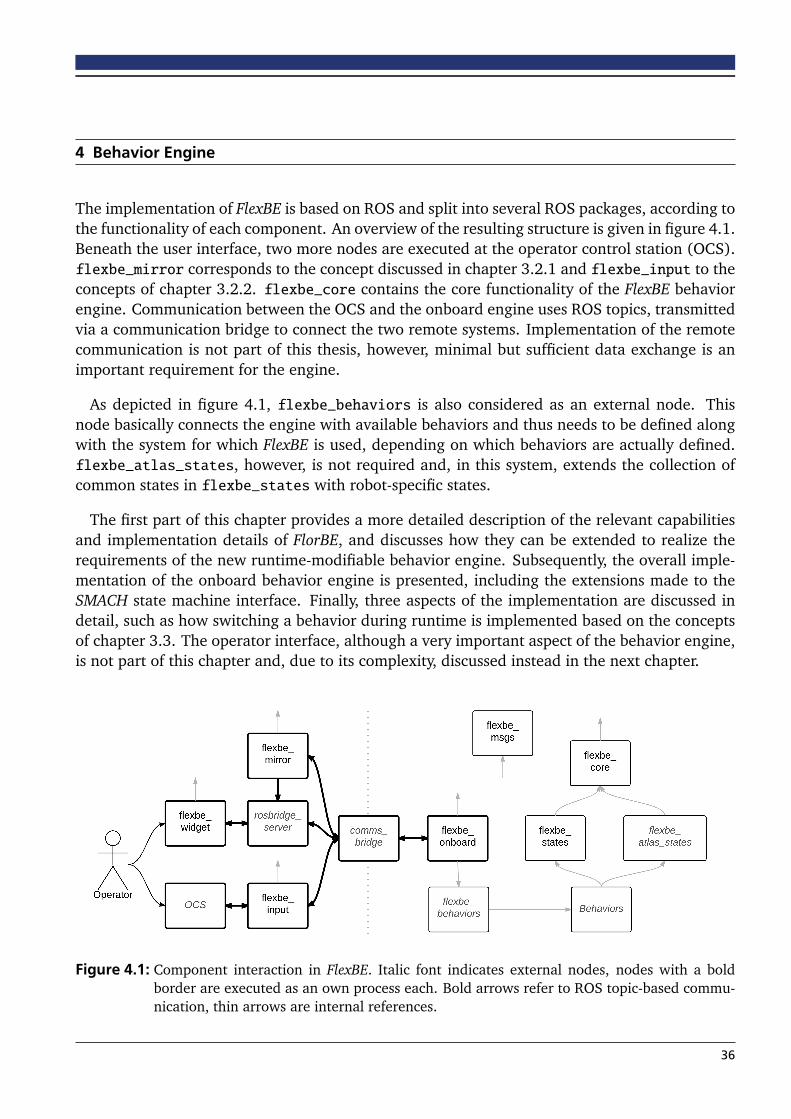
4 Behavior Engine
The implementation of FlexBE is based on ROS and split into several ROS packages, according tothe functionality of each component. An overview of the resulting structure is given in figure 4.1.Beneath the user interface, two more nodes are executed at the operator control station (OCS).flexbe_mirror corresponds to the concept discussed in chapter 3.2.1 and flexbe_input to theconcepts of chapter 3.2.2. flexbe_core contains the core functionality of the FlexBE behaviorengine. Communication between the OCS and the onboard engine uses ROS topics, transmittedvia a communication bridge to connect the two remote systems. Implementation of the remotecommunication is not part of this thesis, however, minimal but sufficient data exchange is animportant requirement for the engine.
As depicted in figure 4.1, flexbe_behaviors is also considered as an external node. Thisnode basically connects the engine with available behaviors and thus needs to be defined alongwith the system for which FlexBE is used, depending on which behaviors are actually defined.flexbe_atlas_states, however, is not required and, in this system, extends the collection ofcommon states in flexbe_states with robot-specific states.
The first part of this chapter provides a more detailed description of the relevant capabilitiesand implementation details of FlorBE, and discusses how they can be extended to realize therequirements of the new runtime-modifiable behavior engine. Subsequently, the overall imple-mentation of the onboard behavior engine is presented, including the extensions made to theSMACH state machine interface. Finally, three aspects of the implementation are discussed indetail, such as how switching a behavior during runtime is implemented based on the conceptsof chapter 3.3. The operator interface, although a very important aspect of the behavior engine,is not part of this chapter and, due to its complexity, discussed instead in the next chapter.
Figure 4.1: Component interaction in FlexBE. Italic font indicates external nodes, nodes with a boldborder are executed as an own process each. Bold arrows refer to ROS topic-based commu-nication, thin arrows are internal references.
36

4.1 Foundations
FlorBE [37] as a basis for the new behavior framework already provides a solid set of fea-tures and certain specific extension points. The concept of behavior specification, as defined byFlorBE, is also applicable for the newly developed framework and will therefore be presentedin this section. Also, operator interaction with the behavior is done by relying on FlorBE. How-ever, some specifics of operator interaction have to be extended or modified in order to enablemore capable commands such as behavior modification. Furthermore, a new user interfacewill replace the behavior control widget and will extend the existing communication protocol,especially regarding robustness and feedback.
4.1.1 Behavior Specification
In FlorBE, behaviors are specified by two documents. The first one is the so-called BehaviorManifest. This manifest is represented by an XML document as shown in listing 4.1. and containsall meta information about the respective behavior, such as its unique name, its author, and thedate of its creation. Furthermore, the manifest defines the interface of the respective behavior.The interface consists of two parts. The first part are the behavior parameters. Each parameterhas a certain type, for example text, numeric, or boolean, and can be referenced by using itsunique name. The values of parameters are chosen by the operator each time a behavior isstarted and then remain constant during execution. The second part is the declaration whichother behaviors are included in the current behavior. For this purpose, their unique names arelisted and, when starting a behavior, their respective parameters are loaded as well.
Finally, the manifest points to the corresponding behavior implementation, which is the sec-ond document. The behavior implementation is a Python class inheriting from the behaviorsuperclass provided by FlorBE and can be located in an arbitrary Python module. Typically, each
1 <?xml ve r s ion=" 1.0 " encoding="UTF−8" ?>23 <behavior name=" Get Up">4 <executable package_path=" f lo r_behav io r_ge t_up . get_up_sm " c lass="GetUpSM" />5 <author>Philipp Schillinger</author>6 <descr ipt ion>7 A behavior that lets the robot stand up when lying on the ground .8 </ descr ipt ion>9
10 <params>11 <param type=" numeric " name=" t ime fa c to r " default=" 1.0 " labe l=" Timefactor ( m u l t i p l i e r ) " hint=
"How f a s t a motion i s executed . ">12 <min value=" 0.1 " />13 <max value=" 5.0 " />14 </param>15 </params>1617 </ behavior>
Listing 4.1: Example for a behavior manifest as used in FlorBE.
4.1 Foundations 37
behavior implementation is placed in a separate ROS package. However, it is also possible togroup multiple behaviors and only use a single ROS package for this group.
When selecting a behavior to be executed, the onboard engine will receive a message repre-senting a start request and specifying the target behavior. This specification is done by providingthe reference to the behavior implementation as given by the above mentioned manifest. Therespective class is then imported, instantiated and executed. In addition, each start request de-fines values for the behavior parameters which then are used for execution. The core part ofeach behavior implementation is its state machine. Built upon SMACH [5], this state machineworks according to the definitions made in section 3.1 and supports userdata for data exchangebetween single states as well as the Autonomy Level for regulating autonomous execution.
SMACH is extended to support all required features by an inheritance chain where each classof the chain adds a new basic feature to custom states and state machines, respectively. Anoverview of the old inheritance chain, as provided by FlorBE is given, in figure 4.4. This inheri-tance has been significantly extended, as presented in section 4.2.1. Also, although the conceptof behavior specification is still applicable, creating and modifying these two documents man-ually does not meet the defined requirements of intuitive behavior definition and will thus begenerated automatically from a model definition in FlexBE.
4.1.2 Operator Interaction
Operator interaction in FlorBE relied on a minimal widget for sending simple commands, suchas forcing a transition or changing the Autonomy Level. It has mainly been created for expertusers and provided no support to the operator for making the correct decisions. A screenshot ofthis behavior control widget is given in figure 4.2. What has proven to be helpful in the way thiswidget is realized is that it is highly context-aware when executing a behavior and only providesinteraction options which are actually executable in the current situation.
Communication between the OCS and the onboard engine in order to send commands fromthe behavior control widget to the executed behaviors, was realized using ROS topics. Also,monitoring of the current state of the behavior has been realized this way, using a simple ver-sion of the Behavior Mirror, of which an improved version is presented later in this chapter.However, FlorBE did not enable to get direct feedback regarding the execution status of an is-sued command back to the operator control widget. This is an important aspect which has to beadded in the improved version of the operator interface.
Figure 4.2: The simple behavior control widget of FlorBE.
4.1 Foundations 38

4.2 Onboard Executive
Based on the foundations provided by FlorBE, the onboard behavior executive is responsible forrealizing all commands sent by the operator. Most important, on receiving a start command, itwill prepare the specified behavior and start its execution. While most parts of the basic onboardexecutive can be used as available in FlorBE, this particular part of starting new behaviors hasto be almost completely reworked. The reason for this is that now, behavior execution shouldnot block all starting requests received in the meantime, but check instead if a switch to thenewly received behavior is possible and perform this switch. In addition, robustness has beenincreased along with these extensions and more precise feedback during the whole process ofbehavior preparation is now available.
As depicted in figure 4.3, starting a new behavior is divided into several steps. Each step iscontained in a try/catch block to detect and handle possible failure. Furthermore, each startrequest is processed in a separate background worker thread. In the worst case, this threadwill fail to execute and thus simply drop the start request. The stability of the system, espe-cially of other components, is not at all affected. The same subsequently applies for behaviorexecution itself, which is performed in the same background thread as starting. This approachprovides more robustness against failure of behavior execution and has been added as part ofthe extensions to FlorBE for this thesis.
When a starting message is received, it will specify which behavior should be started and,if required, indicate changes to the available version of this behavior. Thus, the first step ofprocessing a start request is to load the source code corresponding to the specified behavior,generate the code to be executed from the probably indicated changes, and store it in a tempo-rary file where it incorporates a conventional class implementation. This Python class is thenimported and instantiated in the second step. Since behaviors can also include other behav-iors, the third step consists of importing all embedded behaviors and instantiating them as well.Fourth, the behavior parameters are set to their specified values for this execution. Finally, allstates used by this behavior are instantiated and the behavior state machine is composed. Af-ter completion, the behavior is ready for execution and will be started if no other behavior is
Figure 4.3: Process of starting a new behavior as specified by receiving a BehaviorSelection message.
4.2 Onboard Executive 39

1 package = __import__ ( " tmp_%d " % msg . behavior_id , fromlist=[" tmp_%d " % msg . behavior_id ])2 clsmembers = inspect . getmembers (package ,3 lambda member : inspect . isclass (member ) and member . __module__ == package . __name__ )4 beclass = clsmembers [0][1]5 be = beclass ()67 # . . . e x e c u t e behav io r . . .89 del (sys . modules [ " tmp_%d " % be_id ])
Listing 4.2: Runtime import of a behavior by the onboard engine as executed in step two of starting anew behavior.
currently running. What happens if there already is another behavior running is described insection 4.4.
Importing source code at runtime has already been discussed in chapter 2.3. Python enablesthis functionality by providing the command __import__ to import a specific module when re-quired. As shown in listing 7.1, a behavior is imported by providing a reference to the generatedtemporary source code file and can be instantiated afterwards. After having finished executionof a behavior, it is important to remove the imported module. Otherwise, Python would remem-ber this module and would not execute the import command next time, while just using theremembered version and thus the old source code.
Regarding the previously described fourth step, setting the parameters of a behavior includessetting the parameters of all embedded behaviors as well. In order to avoid ambiguous pa-rameter keys, the keys of embedded behaviors have their own namespace which correspondsto the path of the respective behavior inside the state machine of the top-level behavior. Inthe aforementioned third step of starting a behavior, a dictionary of all embedded behaviors iscreated. This dictionary maps the respective state path, and thus the parameter namespace toa certain behavior instantiation. Subsequently, in the fourth step, the key specification is splitinto the key name and its namespace. On this basis, the corresponding behavior instantiation isselected from the dictionary and its respective parameter, as referred by the key name, is set. Ifno namespace is specified for a key, it refers to a parameter of the top-level behavior.
A further extension provided by this thesis is a more precise and helpful operator feedback.The feedback has been improved in three ways. First, a status message always holds the currentstate of execution such as running, finished, or failed. This enables all related components suchas the Behavior Mirror or the user interface to always reliably know if a remote behavior isrunning and adapt accordingly. Second, a heartbeat signal has been added to the onboardexecutive. This heartbeat enables to detect if a connection to the robot has been lost and willwarn the operator in this case. Third, a new behavior logger will not only handle all loggingwhich has to be done onboard, but also makes sure that the logged messages are transferredto the operator control station and will be displayed in the runtime control part of the userinterface. As a result, the operator is immediately and precisely informed about any detectederrors and also will have access to warning messages and more specific feedback than only stateupdates.
4.2 Onboard Executive 40
4.2.1 Inheritance Chain
Providing functionality to states is solved similar to FlorBE by using an inheritance chain forthe state class. In order to implement the desired features according to the concept of thisthesis, FlexBE extends the inheritance chain by adding new classes. Furthermore, the existingclasses have been modified to give more precise feedback and to improve their modularity. Inthis regard, the most significant change is that previously, a state machine subscribed to allcommand topics such as the topic to preempt a state or manually trigger a transition, and whenreceiving a message on one of these topics, it has called the corresponding function of the state.This led to the drawback that a state could only provide its functionality if its containing statemachine also knew about it and supported it. In the new approach, each state itself subscribesto its respectively required topic, using a cached proxy subscriber, and waits for commandsindependently. As a result, it is completely transparent to the state machine which functionalityis offered by its states.
Figure 4.4 shows the previous execution flow of the old inheritance chain used by FlorBE. Incontrast, 4.5 gives an overview of the new inheritance chain implemented for FlexBE. In thefollowing, each of the classes in the inheritance chain is briefly described and its functionality ispresented. Overall, the order of the states in the chain has been changed to better reflect the factthat a manually triggered transition rather substitutes the result of the user-defined conditionchecking, whereas a triggered preemption is a more important command and should be checkedearlier. Improved modularity is another extension which applies to all states in general. Theidea behind is that it should not make a difference to the state in which type of state machinethey are embedded. In FlorBE, the states only had an interface for triggering their functionalityvia function calls, which needed to be coordinated by the parent state machine. Now, in FlexBE,states themselves listen to ROS topics matching their offered commands.
EventState
The EventState offers the ability to implement certain events during execution of state. Eachstate can specify code to be executed for example when a state is entered from another state byusing the on_enter event. The EventState has already been existing in FlorBE. However, FlexBEoffers the new events on_start and on_stop, which are executed respectively every time thecomplete behavior is started or stopped. Especially the on_stop event is helpful for making surethat all processes triggered by a certain state are correctly terminated, no matter how a behaviorhas been stopped. This helps for example in cases where one state starts a logging process whilerelying on the fact that a second state will stop it before the behavior finishes. But when thebehavior is ended manually, the stop state may not be reached and therefore the starting statecan now use the on_stop event to stop the logging process.
OperatableState
The OperatableState has been the most important state extension in FlorBE. It uses the conceptof an Autonomy Level to decide if a transition is safe to be executed and, if not, prevents itsexecution. It also interfaces with the OperatableStateMachine for monitoring the state execution,
4.2 Onboard Executive 41

Figure 4.4: Flowchart of a state execution in FlorBE
4.2 Onboard Executive 42

Figure 4.5: Flowchart of a state execution in FlexBE
4.2 Onboard Executive 43
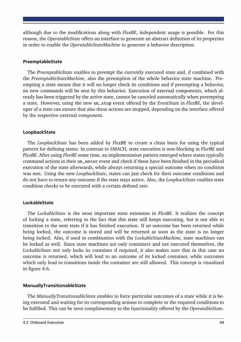
although due to the modifications along with FlexBE, independent usage is possible. For thisreason, the OperatableState offers an interface to generate an abstract definition of its propertiesin order to enable the OperatableStateMachine to generate a behavior description.
PreemptableState
The PreemptableState enables to preempt the currently executed state and, if combined withthe PreemptableStateMachine, also the preemption of the whole behavior state machine. Pre-empting a state means that it will no longer check its conditions and if preempting a behavior,no new commands will be sent by this behavior. Execution of external components, which al-ready has been triggered by the active state, cannot be canceled automatically when preemptinga state. However, using the new on_stop event offered by the EventState in FlexBE, the devel-oper of a state can ensure that also these actions are stopped, depending on the interface offeredby the respective external component.
LoopbackState
The LoopbackState has been added by FlexBE to create a clean basis for using the typicalpattern for defining states. In contrast to SMACH, state execution is non-blocking in FlorBE andFlexBE. After using FlorBE some time, an implementation pattern emerged where states typicallycommand actions in their on_enter event and check if these have been finished in the periodicalexecution of the state afterwards, while always returning a special outcome when no conditionwas met. Using the new LoopbackState, states can just check for their outcome conditions anddo not have to return any outcome if the state stays active. Also, the LoopbackState enables statecondition checks to be executed with a certain defined rate.
LockableState
The LockableState is the most important state extension in FlexBE. It realizes the conceptof locking a state, referring to the fact that this state still keeps executing, but is not able totransition to the next state if it has finished execution. If an outcome has been returned whilebeing locked, the outcome is stored and will be returned as soon as the state is no longerbeing locked. Also, if used in combination with the LockableStateMachine, state machines canbe locked as well. Since state machines are only containers and not executed themselves, theLockableState not only locks its container if required, it also makes sure that in this case nooutcome is returned, which will lead to an outcome of its locked container, while outcomeswhich only lead to transitions inside the container are still allowed. This concept is visualizedin figure 4.6.
ManuallyTransitionableState
The ManuallyTransitionableState enables to force particular outcomes of a state while it is be-ing executed and waiting for its corresponding actions to complete or the required conditions tobe fulfilled. This can be seen complimentary to the functionality offered by the OperatableState.
4.2 Onboard Executive 44
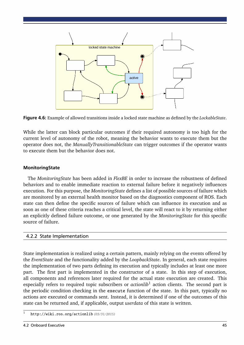
Figure 4.6: Example of allowed transitions inside a locked state machine as defined by the LockableState.
While the latter can block particular outcomes if their required autonomy is too high for thecurrent level of autonomy of the robot, meaning the behavior wants to execute them but theoperator does not, the ManuallyTransitionableState can trigger outcomes if the operator wantsto execute them but the behavior does not.
MonitoringState
The MonitoringState has been added in FlexBE in order to increase the robustness of definedbehaviors and to enable immediate reaction to external failure before it negatively influencesexecution. For this purpose, the MonitoringState defines a list of possible sources of failure whichare monitored by an external health monitor based on the diagnostics component of ROS. Eachstate can then define the specific sources of failure which can influence its execution and assoon as one of these criteria reaches a critical level, the state will react to it by returning eitheran explicitly defined failure outcome, or one generated by the MonitoringState for this specificsource of failure.
4.2.2 State Implementation
State implementation is realized using a certain pattern, mainly relying on the events offered bythe EventState and the functionality added by the LoopbackState. In general, each state requiresthe implementation of two parts defining its execution and typically includes at least one morepart. The first part is implemented in the constructor of a state. In this step of execution,all components and references later required for the actual state execution are created. Thisespecially refers to required topic subscribers or actionlib1 action clients. The second part isthe periodic condition checking in the execute function of the state. In this part, typically noactions are executed or commands sent. Instead, it is determined if one of the outcomes of thisstate can be returned and, if applicable, output userdata of this state is written.
1 http://wiki.ros.org/actionlib (03/31/2015)
4.2 Onboard Executive 45

Most of the implemented states trigger a certain action which is executed while the state isactive. Commanding this action is done in an optional part, relying on the on_enter eventdefined by the EventState. This function is executed once when the state is entered and can beused for sending commands in order to start execution of the desired actions. Further availableevents can be used depending on the required functionality of the state. However, a developershould always keep in mind that a behavior can be preempted at any time and also outcomes,forcing the state to transition, can be commanded externally by the operator. Therefore, it is agood practice to consider using the events on_exit and on_stop for making sure to clean upafter execution. An example state implementation is given in the appendix of this thesis.
Along with the development of the behavior engine itself, several states have been developedas well in order to offer solutions for common aspects of behavior creation and to extend thefunctionality offered by the pure engine. Such states include executing an arbitrary functioncallback as state, in order to convert certain input data to the required type of output data forfuture usage inside the behavior state machine. Function callbacks can also be used to checksimple, very behavior specific conditions and trigger the corresponding outcome based on theresult of this function. Additionally, simple but useful functionality such as waiting for a certainamount of time or sending a log message to the operator using the integrated Behavior Loggeris available as state.
The InputState is a special state of the offered standard state implementations. This state isthe counterpart to the flexbe_input node as presented in chapter 3.2.2. In its on_enter event,this state sends an input request to the operator specifying which type of input data is requiredby the behavior. Afterwards, it periodically checks if the operator has provided this requireddata, retrieves it from the serialized content of the message, and passes it as output userdata tothe next states. The ConcurrentState is another special state. This state can be used to executea set of states simultaneously and return an outcome based on their result and according to aspecified evaluation rule.
4.3 Code Transfer
In FlorBE, specification of the behavior to start with has been realized by sending the uniquename of a behavior within a start message. This allows for compact messages, but has thesignificant disadvantage that behaviors have to be known by the onboard engine. Therefore,only selected behaviors, which have been defined and implemented prior to starting a task andare therefore present onboard, could be selected. Since this thesis targets runtime modifications,it cannot necessarily be assumed that the implementation of a behavior is known in advance.However, it is also not desirable to transfer the full implementation of a behavior during runtimewhile probably being restricted to a slow communication channel.
When deploying the robot for starting to solve a task, the available behaviors can be syn-chronized between the onboard and control station. This provides a good basis, since changesmade during runtime are typically rather small compared to the behaviors itself, which havebeen developed over a longer period of time with the available pre-knowledge of the task. If abehavior has not been modified since the last synchronization, it can still be referred instead ofsending the full specification for starting it. Furthermore, when changes have been made, it is
4.3 Code Transfer 46

not necessary to transmit the whole new version. The changes only can be sent instead, and thenew version can be constructed onboard based on the changes. For this reason, it is importantfor the control station to not only store the latest version of each behavior, but also to keep trackof the version available onboard.
In order to provide the required source code for executing a behavior, the FlexBE Editor userinterface generates it based on the created model. Details regarding this code generation processare presented in chapter 5.2.3. The generated code is then compared to the version of therespective behavior known to onboard and a patch according to chapter 3.3.2 is calculated forgenerating the new version by transmitting minimal data. The differences to be addressed bythe patch are determined by using difflib2, a standard Python library for comparing text. Basedon this result, each difference is considered as a replacement, and the position, represented bythe starting and the ending index, is used along with the content which is supposed to replacethe previous content at this position. The patch is unidirectional, but it provides all informationrequired in this context and contains no redundancy which would require additional bandwidth.In order to make sure that the correct version is constructed from the patch, a checksum of theinitially generated source code is calculated and transmitted along with the patch.
When the behavior specification is received by the onboard engine, the onboard engine willload the referred stored behavior, apply the changes defined by the provided patch, and verifythat the resulting behavior specification matches the desired one by calculating its checksumand comparing it with the one received. If these checksums match, the code transfer has beensuccessful.
4.4 Behavior Switch
Switching a behavior is implemented very similar to starting one. As already mentioned insection 4.2, each behavior is executed in its own background worker thread. Thus, the intentionto switch the currently running behavior to a new version, is indicated by just sending a startrequest containing the modifications to be applied. The way how a start request is realized andhow the modifications are specified, has been discussed in the previous section. In case of abehavior switch the same format is sent, while the fact that the specified behavior matches thecurrently running behavior indicates that a switch will be performed.
When a start request for a new behavior version is received, the first steps of preparing thebehavior are the same as described in section 4.2. They are completely independent from thecurrently running behavior. Once a behavior is ready to be started, which means all of its stateshave been instantiated and the state machine is composed, it checks if a behavior is alreadyrunning. If there is one, the actual behavior switch is induced.
As shown by figure 4.7, a series of checks is performed first in order to verify if switchingis possible. For example, it might be the case that the preempt command message sent to theprevious behavior has been lost for some reason and the received behavior is actually not a newversion of the running behavior, but a completely different one instead. In practice, the operatorwould not have received a confirmation for successful execution of the preempt command, and2 https://docs.python.org/2/library/difflib.html (03/31/2015)
4.4 Behavior Switch 47
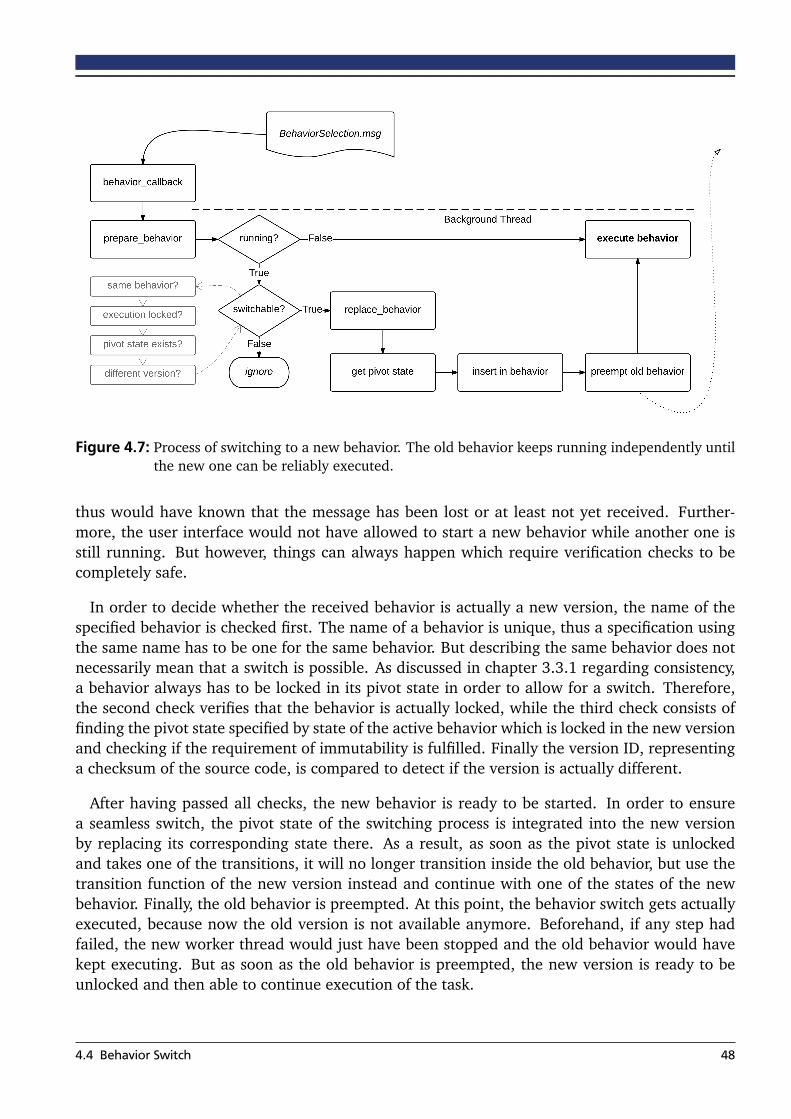
Figure 4.7: Process of switching to a new behavior. The old behavior keeps running independently untilthe new one can be reliably executed.
thus would have known that the message has been lost or at least not yet received. Further-more, the user interface would not have allowed to start a new behavior while another one isstill running. But however, things can always happen which require verification checks to becompletely safe.
In order to decide whether the received behavior is actually a new version, the name of thespecified behavior is checked first. The name of a behavior is unique, thus a specification usingthe same name has to be one for the same behavior. But describing the same behavior does notnecessarily mean that a switch is possible. As discussed in chapter 3.3.1 regarding consistency,a behavior always has to be locked in its pivot state in order to allow for a switch. Therefore,the second check verifies that the behavior is actually locked, while the third check consists offinding the pivot state specified by state of the active behavior which is locked in the new versionand checking if the requirement of immutability is fulfilled. Finally the version ID, representinga checksum of the source code, is compared to detect if the version is actually different.
After having passed all checks, the new behavior is ready to be started. In order to ensurea seamless switch, the pivot state of the switching process is integrated into the new versionby replacing its corresponding state there. As a result, as soon as the pivot state is unlockedand takes one of the transitions, it will no longer transition inside the old behavior, but use thetransition function of the new version instead and continue with one of the states of the newbehavior. Finally, the old behavior is preempted. At this point, the behavior switch gets actuallyexecuted, because now the old version is not available anymore. Beforehand, if any step hadfailed, the new worker thread would just have been stopped and the old behavior would havekept executing. But as soon as the old behavior is preempted, the new version is ready to beunlocked and then able to continue execution of the task.
4.4 Behavior Switch 48
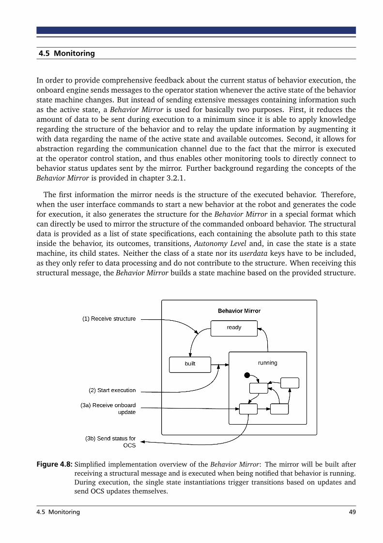
4.5 Monitoring
In order to provide comprehensive feedback about the current status of behavior execution, theonboard engine sends messages to the operator station whenever the active state of the behaviorstate machine changes. But instead of sending extensive messages containing information suchas the active state, a Behavior Mirror is used for basically two purposes. First, it reduces theamount of data to be sent during execution to a minimum since it is able to apply knowledgeregarding the structure of the behavior and to relay the update information by augmenting itwith data regarding the name of the active state and available outcomes. Second, it allows forabstraction regarding the communication channel due to the fact that the mirror is executedat the operator control station, and thus enables other monitoring tools to directly connect tobehavior status updates sent by the mirror. Further background regarding the concepts of theBehavior Mirror is provided in chapter 3.2.1.
The first information the mirror needs is the structure of the executed behavior. Therefore,when the user interface commands to start a new behavior at the robot and generates the codefor execution, it also generates the structure for the Behavior Mirror in a special format whichcan directly be used to mirror the structure of the commanded onboard behavior. The structuraldata is provided as a list of state specifications, each containing the absolute path to this stateinside the behavior, its outcomes, transitions, Autonomy Level and, in case the state is a statemachine, its child states. Neither the class of a state nor its userdata keys have to be included,as they only refer to data processing and do not contribute to the structure. When receiving thisstructural message, the Behavior Mirror builds a state machine based on the provided structure.
Figure 4.8: Simplified implementation overview of the Behavior Mirror: The mirror will be built afterreceiving a structural message and is executed when being notified that behavior is running.During execution, the single state instantiations trigger transitions based on updates andsend OCS updates themselves.
4.5 Monitoring 49
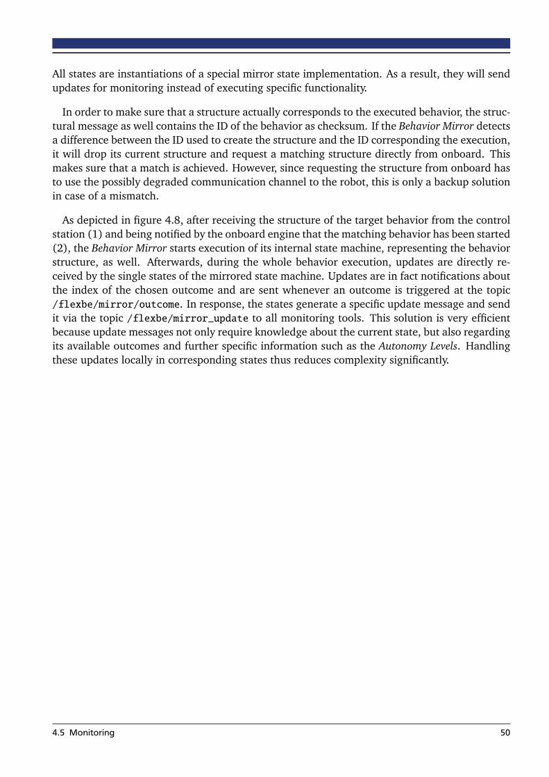
All states are instantiations of a special mirror state implementation. As a result, they will sendupdates for monitoring instead of executing specific functionality.
In order to make sure that a structure actually corresponds to the executed behavior, the struc-tural message as well contains the ID of the behavior as checksum. If the Behavior Mirror detectsa difference between the ID used to create the structure and the ID corresponding the execution,it will drop its current structure and request a matching structure directly from onboard. Thismakes sure that a match is achieved. However, since requesting the structure from onboard hasto use the possibly degraded communication channel to the robot, this is only a backup solutionin case of a mismatch.
As depicted in figure 4.8, after receiving the structure of the target behavior from the controlstation (1) and being notified by the onboard engine that the matching behavior has been started(2), the Behavior Mirror starts execution of its internal state machine, representing the behaviorstructure, as well. Afterwards, during the whole behavior execution, updates are directly re-ceived by the single states of the mirrored state machine. Updates are in fact notifications aboutthe index of the chosen outcome and are sent whenever an outcome is triggered at the topic/flexbe/mirror/outcome. In response, the states generate a specific update message and sendit via the topic /flexbe/mirror_update to all monitoring tools. This solution is very efficientbecause update messages not only require knowledge about the current state, but also regardingits available outcomes and further specific information such as the Autonomy Levels. Handlingthese updates locally in corresponding states thus reduces complexity significantly.
4.5 Monitoring 50
5 Behavior Operation
The user interface of FlexBE is a very important part of the behavior framework. Not only doesit allow to start and stop behavior execution, it also significantly facilitates development of newbehaviors and provides access to all features offered by the onboard engine. In contrast to thepreviously described behavior engine, the software components presented in this section runat the operator control station (OCS). This includes the user interface, an input manager forproviding specific data, and the already mentioned Behavior Mirror for monitoring.
The main focus of this chapter is the user interface and its capabilities to not only operatebehaviors, but also to define them. Having these two capabilities realized in one single userinterface is rather complex compared to having two independent interfaces. However, sincethe framework enables runtime modifications, having independent interfaces is not sufficientanymore. During execution, there are several restrictions regarding when and how a behaviorcan be modified. These restrictions ensure consistency and have already been discussed inchapter 3.3.1. Therefore, combining both aspects in one single user interface guarantees thatall conditions for editing a behavior are met.
In this chapter, an overview of the approach of the user interface and its basis is given at first.Subsequently, the second section focuses on defining new and modifying existing behaviors andpresents how these behaviors are provided to the onboard engine. This section is followed bya section focused on operating behaviors during runtime. Finally, new concepts that supportcommunication with the onboard engine in addition to the Behavior Mirror are introduced.
5.1 Approach
The main purpose of the user interface is to provide the functionality offered by the onboard partof FlexBE to the operator in a user-friendly way. Since the concept of FlexBE relies on havingthe robot and the operator work together as a team, not only the robot has to be perfectlyintegrated into the system, but also the operator. Especially mechanisms to reduce the cognitiveload the operator has to take when executing a behavior, and even more a developer has totake when specifying behaviors, are an important focus of the chosen approach for the userinterface. For this reason, not only are state machines drawn in an intuitive way to quicklyprovide an overview of their structure, but also has a number of usability features been addedsuch as visualizing the userdata dataflow inside a state machine, offering completion suggestionswhen entering parameter values or userdata keys, providing detailed documentation wheneverpossibly of advantage, or indicating errors as soon as they are made.
Although the whole system is based on ROS, the user interface itself is realized as a GoogleChrome App. Main reason for this decision is the great flexibility to design an intuitive anduseful interface for operating behaviors. The combination of HTML, CSS, and JavaScript allowsto easily specify each single aspect of the user interface. In order to connect the user interfaceto ROS, Rosbridge1 is used to communicate to the other ROS nodes and RoslibJS2 provides a1 http://wiki.ros.org/rosbridge_suite (03/31/2015)2 http://wiki.ros.org/roslibjs (03/31/2015)
51
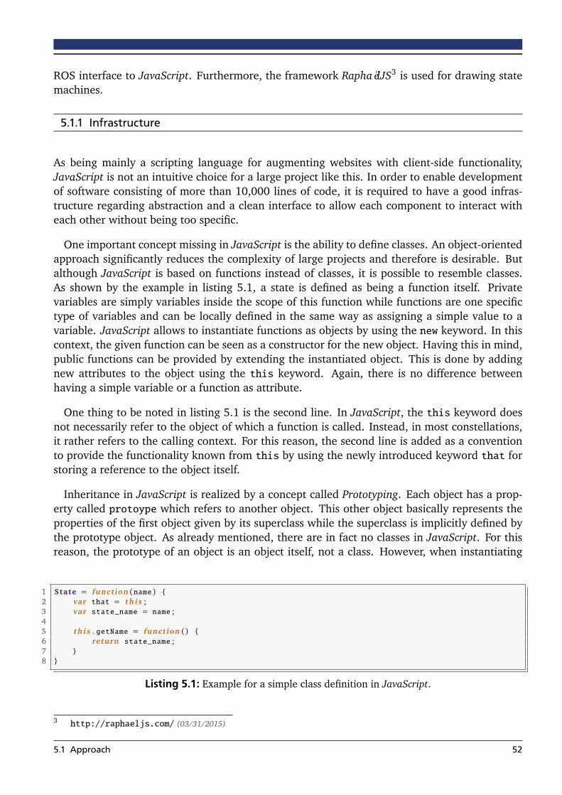
ROS interface to JavaScript. Furthermore, the framework RaphaëlJS3 is used for drawing statemachines.
5.1.1 Infrastructure
As being mainly a scripting language for augmenting websites with client-side functionality,JavaScript is not an intuitive choice for a large project like this. In order to enable developmentof software consisting of more than 10,000 lines of code, it is required to have a good infras-tructure regarding abstraction and a clean interface to allow each component to interact witheach other without being too specific.
One important concept missing in JavaScript is the ability to define classes. An object-orientedapproach significantly reduces the complexity of large projects and therefore is desirable. Butalthough JavaScript is based on functions instead of classes, it is possible to resemble classes.As shown by the example in listing 5.1, a state is defined as being a function itself. Privatevariables are simply variables inside the scope of this function while functions are one specifictype of variables and can be locally defined in the same way as assigning a simple value to avariable. JavaScript allows to instantiate functions as objects by using the new keyword. In thiscontext, the given function can be seen as a constructor for the new object. Having this in mind,public functions can be provided by extending the instantiated object. This is done by addingnew attributes to the object using the this keyword. Again, there is no difference betweenhaving a simple variable or a function as attribute.
One thing to be noted in listing 5.1 is the second line. In JavaScript, the this keyword doesnot necessarily refer to the object of which a function is called. Instead, in most constellations,it rather refers to the calling context. For this reason, the second line is added as a conventionto provide the functionality known from this by using the newly introduced keyword that forstoring a reference to the object itself.
Inheritance in JavaScript is realized by a concept called Prototyping. Each object has a prop-erty called protoype which refers to another object. This other object basically represents theproperties of the first object given by its superclass while the superclass is implicitly defined bythe prototype object. As already mentioned, there are in fact no classes in JavaScript. For thisreason, the prototype of an object is an object itself, not a class. However, when instantiating
1 State = function (name ) {2 var that = th i s ;3 var state_name = name ;45 th i s . getName = function () {6 return state_name ;7 }8 }
Listing 5.1: Example for a simple class definition in JavaScript.
3 http://raphaeljs.com/ (03/31/2015)
5.1 Approach 52

1 Statemachine = function (name ) {2 State . apply ( this , [name ]) ;3 var that = th i s ;4 var states = [ ] ;56 th i s . addState = function ( new_state ) {7 return states . push ( new_state ) ;8 }9 }
10 Statemachine . p r o t o t y p e = Ob j e c t . create ( State . p r o t o t y p e ) ;
Listing 5.2: Simple example for class inheritance in JavaScript.
a new object, the prototype of the constructor function is automatically copied as prototype ofthe new object.
An example for this process is given in listing 5.2. In line two, the properties of the prototypeof the new object are set. This basically corresponds to calling the constructor of the superclassin conventional class-based inheritance. In addition, the prototype of the function Statema-chine, which represents the class of all state machine objects in this example, has to be set to anew instance of the State prototype. This makes sure that each new state machine object willreceive a state prototype.
In summary, applying the concept of object orientation to JavaScript is not always intuitive andsometimes hard to understand. But it is possible and when being used to it, the same patternsas in object-oriented programming can be realized in a similar way. Further explanations anddetails can be found at [41].
In addition to having a basis for implementing the desired concepts in JavaScript, it is requiredto split the whole user interface into separated blocks of functionality, but also to combine HTMLand CSS with JavaScript as tools for specifying layout structure and appearance. All static partsof the user interface are defined in HTML, while there is a container with a unique ID for eachspot where dynamic content has to be added later using JavaScript. In addition, CSS definitionsspecify the visual properties of all displayed objects and also provide pre-defined style classesfor objects later created dynamically. Furthermore, a dedicated event coordinator realized inJavaScript directs events occurring at the static components defined in HTML to the modulesimplementing the respective functionality in JavaScript. The JavaScript part itself is split intoseveral modules in order to reduce complexity and provide abstraction. In the following, eachmodule is briefly described.
User Interface (UI)
This module is responsible for realizing the dynamic part of the user interface which cannotbe defined in HTML. Its structure is closely oriented on the visual components. Each of themain views, which are described in detail in the next section, is represented by an own class.Additional panels, such as a panel for displaying the properties of a state, are realized in anadditional sub-module.
5.1 Approach 53
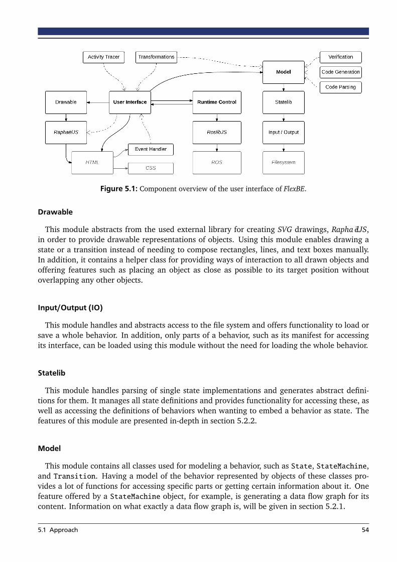
Figure 5.1: Component overview of the user interface of FlexBE.
Drawable
This module abstracts from the used external library for creating SVG drawings, RaphaëlJS,in order to provide drawable representations of objects. Using this module enables drawing astate or a transition instead of needing to compose rectangles, lines, and text boxes manually.In addition, it contains a helper class for providing ways of interaction to all drawn objects andoffering features such as placing an object as close as possible to its target position withoutoverlapping any other objects.
Input/Output (IO)
This module handles and abstracts access to the file system and offers functionality to load orsave a whole behavior. In addition, only parts of a behavior, such as its manifest for accessingits interface, can be loaded using this module without the need for loading the whole behavior.
Statelib
This module handles parsing of single state implementations and generates abstract defini-tions for them. It manages all state definitions and provides functionality for accessing these, aswell as accessing the definitions of behaviors when wanting to embed a behavior as state. Thefeatures of this module are presented in-depth in section 5.2.2.
Model
This module contains all classes used for modeling a behavior, such as State, StateMachine,and Transition. Having a model of the behavior represented by objects of these classes pro-vides a lot of functions for accessing specific parts or getting certain information about it. Onefeature offered by a StateMachine object, for example, is generating a data flow graph for itscontent. Information on what exactly a data flow graph is, will be given in section 5.2.1.
5.1 Approach 54

Runtime Control (RC)
This module interfaces ROS by using RoslibJS and offers functionality to send and receive ROSmessages. Furthermore, it contains the runtime controller class for managing the runtime stateand deciding which actions are allowed with respect to a possibly running onboard behavior.Details to this module are given in all parts of section 5.3.
Finally, some top-level classes such as the previously mentioned event coordinator are con-tained in the root module, and further auxiliary modules containing CSS definitions, images andJavaScript code for testing, are available as well.
5.1.2 Operator Views
The user interface itself is separated into four different sections, called views. Each view has aclearly defined purpose and allows for concentrating on one specific aspect. The operator canswitch between these views at any time using one of the four view buttons in the menu bar. Inaddition to the view buttons, the menu bar always indicates the connection status to the robotand contains further buttons defined by each of the views which are only displayed when therespective view is active.
The first view is the Behavior Dashboard. Its purpose is to give a high-level overview of thebehavior and foremost define its interface. Thus, the view provided by the Behavior Dashboardcan be seen as an outer view or black box view onto the behavior. Although not strictly divided
Figure 5.2: The four views of the FlexBE user interface.
5.1 Approach 55

regarding this aspect, the dashboard loosely corresponds to the Behavior Manifest document.Meta-data such as the name of the behavior and its author are specified here, as well as theparameters of the behavior. As depicted in figure 5.3, defining parameters for the behavioris assisted by a specific Behavior Parameters panel. Further panels at the dashboard help toadd private variables, which can be seen as a persistent configuration of the behavior, defaultuserdata and private functions. Also, the interface of this behavior, when embedded in anotherbehavior, can be defined here.
The next two views, the Statemachine Editor and the Runtime Control, are presented in-depthin the next two sections. Roughly speaking, the Statemachine Editor complements the BehaviorDashboard when defining a behavior. But while the dashboard provides an outer view focusedon the interface, the editor provides an inner view and defines the implementation of a behavioras given by its state machine. The Runtime Control on the other hand concentrates on providinga good monitoring of behavior execution and enables the operator to send commands to theexecuted behavior.
Finally, the fourth view offers the possibility to configure the FlexBE user interface itself. Set-tings and references to the file system can be specified here and are stored when closing the userinterface. For example, the communication with Rosbridge can be configured here and foldersfor importing available state definitions can be chosen.
In addition to the views, there is a terminal panel, providing detailed feedback to the operatorwhenever commanded actions cannot be executed or relevant information is available. Thisterminal is hidden most of the time and only automatically displayed if required. Anotheraddition is the Tool Overlay. As shown in figure 5.4, a set of commands is directly accessibleusing this overlay. This overlay can be displayed by pressing the Control and the Space keys.Moving the cursor across one of the commands before releasing the keys again will immediatelytrigger this command. Otherwise, the overlay stays displayed until a command is selected orit is hidden again. Besides accessing the most frequently used commands, this overlay lists allpast modifications to the behavior and allows to jump back and forth in time to any of thelisted versions. A command line input at the bottom also enables execution of more advancedcommands.
Figure 5.3: Configuring the properties of a behavior parameter.
5.1 Approach 56

Figure 5.4: The Tool Overlay appears around the cursor position and offers quick commands.
5.2 Statemachine Editor
The Statemachine Editor view is a powerful tool for developing new behaviors or getting anoverview of existing ones. It consists of a large drawing area where all states of the statemachine are visualized as boxes and are connected by labeled arrows indicating existing tran-sitions between them. The label of a transition corresponds to one of the outcomes of theoutgoing state. When this state returns the specified outcome, this transition is taken and exe-cution is continued with the state to which the transition arrow points. In addition, the arrowsare colored corresponding to their required Autonomy Level. The outcomes of the containingstate machine are drawn as terminating dots, labeled with their respective outcome. States aswell can connect their outcomes to those dots which will make the state machine terminatewhen one of these outcomes is returned.
Figure 5.5 shows an example for a state machine visualized by the Statemachine Editor. Asdepicted, for each one of the yellow states, its state instantiation name and the name of theclass of its state implementation is given. The white state is a state machine itself and containsthree inner states. Although not shown in this simple example, whole behaviors as well can beembedded into a state machine as states, which is indicated by a purple state box giving thename of the respective behavior instead of the state implementation class.
Being able to develop behaviors in such an intuitive way without the need to specify eachsingle state by writing Python code, and especially having an overview of the whole behaviorstate machine at any time during development, are important prerequisites for modifying be-haviors during runtime. As stated in chapter 1.1, this feature implies strict requirements for thedevelopment of behaviors. Not only must the operator be able to make small modifications onits own without being a developer himself or being able to write Python code, but also the de-velopment of behavior modifications must be guided and supervised by auxiliary tools to verifythe correctness of made changes.
5.2 Statemachine Editor 57
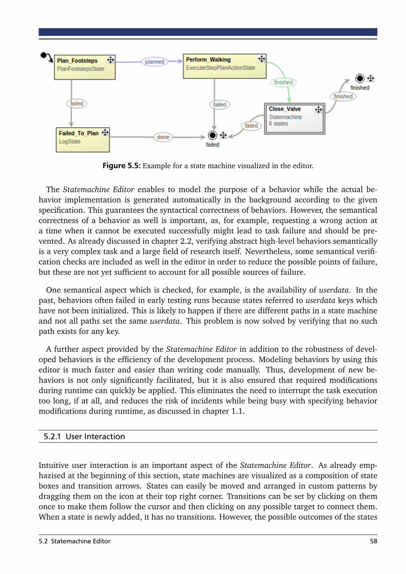
Figure 5.5: Example for a state machine visualized in the editor.
The Statemachine Editor enables to model the purpose of a behavior while the actual be-havior implementation is generated automatically in the background according to the givenspecification. This guarantees the syntactical correctness of behaviors. However, the semanticalcorrectness of a behavior as well is important, as, for example, requesting a wrong action ata time when it cannot be executed successfully might lead to task failure and should be pre-vented. As already discussed in chapter 2.2, verifying abstract high-level behaviors semanticallyis a very complex task and a large field of research itself. Nevertheless, some semantical verifi-cation checks are included as well in the editor in order to reduce the possible points of failure,but these are not yet sufficient to account for all possible sources of failure.
One semantical aspect which is checked, for example, is the availability of userdata. In thepast, behaviors often failed in early testing runs because states referred to userdata keys whichhave not been initialized. This is likely to happen if there are different paths in a state machineand not all paths set the same userdata. This problem is now solved by verifying that no suchpath exists for any key.
A further aspect provided by the Statemachine Editor in addition to the robustness of devel-oped behaviors is the efficiency of the development process. Modeling behaviors by using thiseditor is much faster and easier than writing code manually. Thus, development of new be-haviors is not only significantly facilitated, but it is also ensured that required modificationsduring runtime can quickly be applied. This eliminates the need to interrupt the task executiontoo long, if at all, and reduces the risk of incidents while being busy with specifying behaviormodifications during runtime, as discussed in chapter 1.1.
5.2.1 User Interaction
Intuitive user interaction is an important aspect of the Statemachine Editor. As already emp-hazised at the beginning of this section, state machines are visualized as a composition of stateboxes and transition arrows. States can easily be moved and arranged in custom patterns bydragging them on the icon at their top right corner. Transitions can be set by clicking on themonce to make them follow the cursor and then clicking on any possible target to connect them.When a state is newly added, it has no transitions. However, the possible outcomes of the states
5.2 Statemachine Editor 58

which are not yet connected by a transition, are displayed inside the state box. Clicking on oneof these outcomes also triggers the process of connecting a transition.
Since state machines itself and other behaviors, which consist of at least one top-level statemachine, can be used as states as well, they enable the specification of hierarchical state ma-chines. In order to navigate this hierarchy, these states can be double-clicked to enter them.Entering means that now, their content is displayed in the editor drawing area. At the top ofthe drawing area is a navigation bar which allows to go up again in the hierarchy. While thecontent of an embedded state machine can be arbitrarily modified, embedded behaviors areread-only because they are not specified as part of the top-level behavior, but by their ownbehavior definition instead.
Furthermore, each state has specific properties, such as parameters. Single-clicking on astate opens the property panel of this state, displayed at the right side of the window. Thispanel enables the developer to change the name of a state and provides specific informationby displaying the state documentation. Also, all properties of the selected state are listed andcan be changed. This includes setting the parameters of this state as well as selecting theappropriate Autonomy Levels of all outcomes. Furthermore, the userdata keys used by this statecan be remapped in order to match available keys of the state machine. This remapping allowsto connect userdata of different states regardless of their internal key name. For state machines,also the available userdata keys and outcomes can be defined since they are not given by a fixedstate implementation.
An example of how the properties panel looks like is given by figure 5.6. While, for example,entering the value of a parameter, as shown in this figure, the documentation of this specificparameter is displayed and also suggestions for possible values to be entered are provided,depending on available global variables, functions, and state specific data such as class variablesof this state implementation. Providing this information is not only a convenience feature, it isan important part of the concept of facilitating the development as much as possible and ofpreventing the developer from entering wrong values. If, for example, a string was given asparameter value and the developer forgot to close the quotes, the input field would immediatelyturn red, indicating an error at this position.
(a) Documentation tooltip (b) Autocompletion
Figure 5.6: Documentation assists the developer by providing the correct values.
5.2 Statemachine Editor 59
Adding a new state opens a panel similar to the state property panel. In this panel, the desiredname of the new state can be given as well as the class name of the state implementation. Inorder to select the correct class and, at the same time, to get an overview of available choices,a list of all known state implementations is displayed in this panel. Each entry in this listnot only contains the class name of this implementation, but also its respective summarizeddocumentation. Selecting the right implementation from this list can take some time, thereforean input field for filtering the list is provided. When starting to type a desired class name intothis field, only classes containing the entered text as part of their name are listed, while classesof which the name starts with the entered text are listed at the top. This enables a quick selectionof the desired class, which is completed by clicking on the corresponding list entry in order touse this class. In case only a single list entry is left due to the entered filter, this class is selectedautomatically.
The data flow graph is an additional tool for supporting the development of new behaviors andespecially helping to quickly understand what is happening in a state machine. When activatingit, the data flow of the state machine’s userdata is displayed instead of the labeled and coloredtransitions between the states. The data flow graph consists of directed edges between all pairsof states where the first state has an output key and the second one the corresponding input key.Or, practically speaking, it visualizes the flow of data from being written by one state to beingread by another state. For the data flow graph, all possible paths are taken into consideration.If a userdata key is not defined by any state before being used as input key, an edge is addedfrom the starting point of the state machine indicating that this data has to be provided by thestate machine as an input key. Similarly, output keys of the state machine create data edges tothe terminating dots representing the outcomes of this outer state machine.
Finally, also tools such as copy and paste of states and groups of states are provided. Selectingmultiple states can be achieved by dragging a selection rectangle across all of them. When copy-ing a group of states, internal transitions, which means that both end points of the respectivetransitions are contained in the selected group, are copied as well. All actions performed bythe user are stored in an activity history, allowing to undo certain actions or redo them again.Furthermore, as presented in section 5.1.2, a Tool Overlay not only makes these actions moreaccessible, but also provides an overview of the whole activity history.
5.2.2 Integration of States
As already mentioned, a list of available state implementations is offered to the developer whenadding a new state. In order to generate this list, the user can provide folders in the Configura-tion view which are then parsed for available state implementations. This seamless integrationof the user interface into the development process is an important factor for enabling use inpractice. It would be very cumbersome if a developer was required to provide information re-garding an implemented state definition manually each time a new one is added. On the otherhand, being able to parse available state implementations allows the developer to just open theeditor and use all defined states without any intermediate step.
Parsing of state implementations is done by the Statelib component of the user interface. TheLibParser recursively traverses all folders specified in the Configuration view and detects files
5.2 Statemachine Editor 60
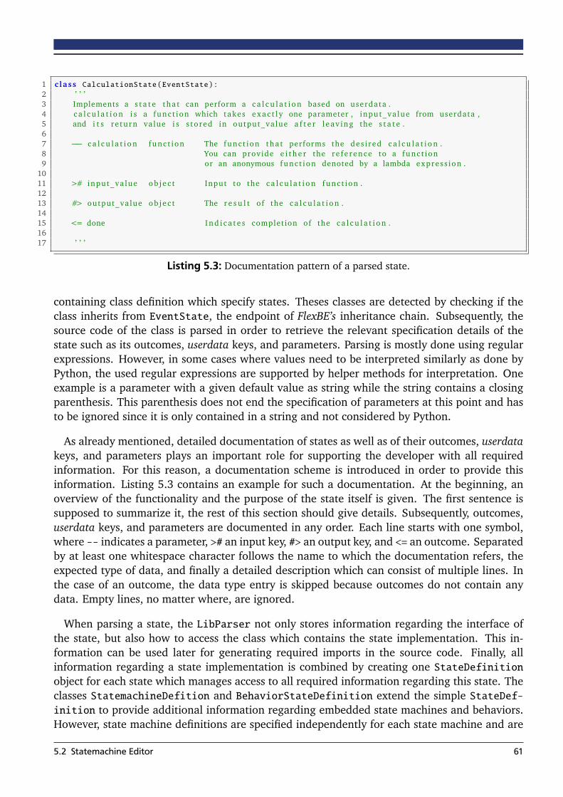
1 c lass CalculationState ( EventState ) :2 ’ ’ ’3 Implements a s t a t e tha t can perform a c a l c u l a t i o n based on userdata .4 c a l c u l a t i o n i s a func t ion which takes e x a c t l y one parameter , input_va lue from userdata ,5 and i t s re turn value i s s to red in output_value a f t e r l eav ing the s t a t e .67 −− c a l c u l a t i o n func t ion The func t ion tha t performs the des i red c a l c u l a t i o n .8 You can provide e i t h e r the re f e rence to a func t ion9 or an anonymous func t ion denoted by a lambda expres s ion .
1011 ># input_va lue o b j e c t Input to the c a l c u l a t i o n func t ion .1213 #> output_value o b j e c t The r e s u l t of the c a l c u l a t i o n .1415 <= done I n d i c a t e s complet ion of the c a l c u l a t i o n .1617 ’ ’ ’
Listing 5.3: Documentation pattern of a parsed state.
containing class definition which specify states. Theses classes are detected by checking if theclass inherits from EventState, the endpoint of FlexBE’s inheritance chain. Subsequently, thesource code of the class is parsed in order to retrieve the relevant specification details of thestate such as its outcomes, userdata keys, and parameters. Parsing is mostly done using regularexpressions. However, in some cases where values need to be interpreted similarly as done byPython, the used regular expressions are supported by helper methods for interpretation. Oneexample is a parameter with a given default value as string while the string contains a closingparenthesis. This parenthesis does not end the specification of parameters at this point and hasto be ignored since it is only contained in a string and not considered by Python.
As already mentioned, detailed documentation of states as well as of their outcomes, userdatakeys, and parameters plays an important role for supporting the developer with all requiredinformation. For this reason, a documentation scheme is introduced in order to provide thisinformation. Listing 5.3 contains an example for such a documentation. At the beginning, anoverview of the functionality and the purpose of the state itself is given. The first sentence issupposed to summarize it, the rest of this section should give details. Subsequently, outcomes,userdata keys, and parameters are documented in any order. Each line starts with one symbol,where -- indicates a parameter, ># an input key, #> an output key, and <= an outcome. Separatedby at least one whitespace character follows the name to which the documentation refers, theexpected type of data, and finally a detailed description which can consist of multiple lines. Inthe case of an outcome, the data type entry is skipped because outcomes do not contain anydata. Empty lines, no matter where, are ignored.
When parsing a state, the LibParser not only stores information regarding the interface ofthe state, but also how to access the class which contains the state implementation. This in-formation can be used later for generating required imports in the source code. Finally, allinformation regarding a state implementation is combined by creating one StateDefinitionobject for each state which manages access to all required information regarding this state. Theclasses StatemachineDefition and BehaviorStateDefinition extend the simple StateDef-inition to provide additional information regarding embedded state machines and behaviors.However, state machine definitions are specified independently for each state machine and are
5.2 Statemachine Editor 61
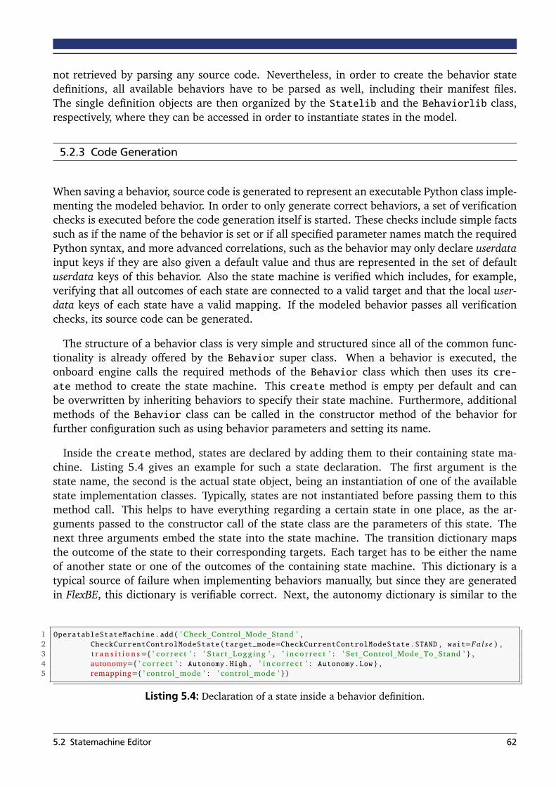
not retrieved by parsing any source code. Nevertheless, in order to create the behavior statedefinitions, all available behaviors have to be parsed as well, including their manifest files.The single definition objects are then organized by the Statelib and the Behaviorlib class,respectively, where they can be accessed in order to instantiate states in the model.
5.2.3 Code Generation
When saving a behavior, source code is generated to represent an executable Python class imple-menting the modeled behavior. In order to only generate correct behaviors, a set of verificationchecks is executed before the code generation itself is started. These checks include simple factssuch as if the name of the behavior is set or if all specified parameter names match the requiredPython syntax, and more advanced correlations, such as the behavior may only declare userdatainput keys if they are also given a default value and thus are represented in the set of defaultuserdata keys of this behavior. Also the state machine is verified which includes, for example,verifying that all outcomes of each state are connected to a valid target and that the local user-data keys of each state have a valid mapping. If the modeled behavior passes all verificationchecks, its source code can be generated.
The structure of a behavior class is very simple and structured since all of the common func-tionality is already offered by the Behavior super class. When a behavior is executed, theonboard engine calls the required methods of the Behavior class which then uses its cre-ate method to create the state machine. This create method is empty per default and canbe overwritten by inheriting behaviors to specify their state machine. Furthermore, additionalmethods of the Behavior class can be called in the constructor method of the behavior forfurther configuration such as using behavior parameters and setting its name.
Inside the create method, states are declared by adding them to their containing state ma-chine. Listing 5.4 gives an example for such a state declaration. The first argument is thestate name, the second is the actual state object, being an instantiation of one of the availablestate implementation classes. Typically, states are not instantiated before passing them to thismethod call. This helps to have everything regarding a certain state in one place, as the ar-guments passed to the constructor call of the state class are the parameters of this state. Thenext three arguments embed the state into the state machine. The transition dictionary mapsthe outcome of the state to their corresponding targets. Each target has to be either the nameof another state or one of the outcomes of the containing state machine. This dictionary is atypical source of failure when implementing behaviors manually, but since they are generatedin FlexBE, this dictionary is verifiable correct. Next, the autonomy dictionary is similar to the
1 OperatableStateMachine . add ( ’ Check_Control_Mode_Stand ’ ,2 CheckCurrentControlModeState ( target_mode=CheckCurrentControlModeState . STAND , wait=F a l s e ) ,3 t r a n s i t i o n s={ ’ c o r r e c t ’ : ’ S tar t_Logg ing ’ , ’ i n c o r r e c t ’ : ’ Set_Control_Mode_To_Stand ’ } ,4 autonomy={ ’ c o r r e c t ’ : Autonomy . High , ’ i n c o r r e c t ’ : Autonomy . Low } ,5 remapping={ ’ control_mode ’ : ’ control_mode ’ })
Listing 5.4: Declaration of a state inside a behavior definition.
5.2 Statemachine Editor 62

transition dictionary but with the difference that an Autonomy Level for each outcome is given.Finally, the remapping dictionary maps internal userdata keys to external ones.
In order to generate the code, which is a sequential representation of the behavior statemachine, the state machine has to be traversed in a certain order. Adding embedded statemachines in the source code works similar to adding a normal state, but instead of providing astate instantiation, a reference to the embedded state machine is given. Thus, when traversingthe hierarchy of state machines, the resulting order has to guarantee that a state machine isalways at a position behind all of its embedded state machines, since Python would not knowthe reference to the respective state machine otherwise. For the states itself, no special order isrequired, since the transition function is given as a mapping of strings. Only exception is the factthat SMACH requires the initial state to be the first state added to a state machine per default.This constraint is also respected by the code generation process. In addition to generating thecode to represent the behavior state machines, the imports for all used states are generated aswell as declaring which external behaviors are contained.
The reduced flexibility constrained by the fixed pattern of generation typically is a significantdrawback of code generation. However, this flexibility is often required for solving more com-plex tasks. Purpose of the code generation process is not enforcing a fixed structure of behaviorswhile restricting the developer to a certain pattern of implementation, but instead, supportingthe developer by automatically providing certain parts of the implementation. Therefore, in ad-dition to the generated code, the developer has the option to edit certain parts of the generatedsource code manually. These sections are explicitly declared in the generated code and whenoverwriting an implementation by a newly generated version, the manual sections will not getlost. This also includes the case where code in the manual sections is modified after a behaviorhas been loaded by the editor, thus allowing even parallel modification of source code in both,the user interface and manually.
There are four manual sections in each behavior. The first one, Manual_Import, is providedprior to the class definition of the behavior and is meant to be used for additional importsrequired by the other manual sections. The Manual_Init section is contained in the constructorof the behavior class and can be used for initialization code and declaring private class variables.The Manual_Create section is located inside the create method between the declaration of allprivate variables, as entered at the Behavior Dashboard, and starting to build the state machine.Thus, this section can be used for advanced calculation of private variables to be used by thestate machine or to be passed as parameters to certain states. Finally, the Manual_Functionssection can be used for manually defining additional helper functions which can be used in theother sections or passed to states.
Generating the source code of a behavior class is definitely the most complex part of thegeneration process, but not the only one. Each behavior implementation is represented by aROS package and, in addition, needs to have a manifest located inside the behaviors folderof the ROS package flexbe_behaviors, while this package needs to have a dependency on thebehavior package. All of these requirements are checked by FlexBE when generating a behaviorand, if missing, are generated as well. This is not only convenient and makes creating newbehaviors faster by being able to just click one single save button instead of creating all requiredfiles and entries additionally, it also ensures consistency and verifies that declarations regarding
5.2 Statemachine Editor 63
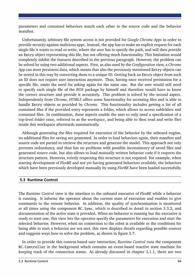
parameters and contained behaviors match each other in the source code and the behaviormanifest.
Unfortunately, arbitrary file system access is not provided for Google Chrome Apps in order toprovide security against malicious apps. Instead, the app has to make an explicit request for eachsingle file it wants to read or write, where the user has to specify the path, and will then providean Entry object representing this file, but not offering much functionality. This limitation wouldcompletely inhibit the features described in the previous paragraph. However, the problem canbe solved by using two additional aspects. First, as also used by the Configuration view, a ChromeApp can store persistent data, which means that also the previously mentioned Entry objects canbe stored in this way by converting them to a unique ID. Getting back an Entry object from suchan ID does not require user interaction anymore. Thus, having once received permission for aspecific file, omits the need for asking again for the same one. But the user would still needto specify each single file of the ROS package by himself and therefore would have to knowthe correct structure and provide it accurately. This problem is solved by the second aspect.Independently from Chrome, HTML5 offers some functionality for accessing files and is able tohandle Entry objects as provided by Chrome. This functionality includes getting a list of allcontained files if the provided entry represents a folder, which allows to access subfolders andcontained files. In combination, these aspects enable the user to only need a specification of atop-level folder once, referred to as the workspace, and being able to then read and write filesinside this workspace afterwards automatically.
Although generating the files required for execution of the behavior by the onboard engine,no additional files for saving are generated. In order to load behaviors again, their manifest andsource code are parsed to retrieve the structure and generate the model. This approach not onlyprevents redundancy, and thus has no problems with possible inconsistency of saved files andgenerated source code, but also allows to load manually written behavior code if it respects thestructure pattern. However, strictly respecting this structure is not required. For example, whenstarting development of FlexBE and not yet having generated behaviors available, the behaviorswhich have been previously developed manually by using FlorBE have been loaded successfully.
5.3 Runtime Control
The Runtime Control view is the interface to the onboard executive of FlexBE while a behavioris running. It informs the operator about the current state of execution and enables to givecommands to the remote behavior. In addition, the quality of synchronization is monitoredat all times using the component RC.Sync, which is described in detail in section 5.3.2, anddocumentation of the active state is provided. When no behavior is running but the executive isready to start one, this view lets the operator specify the parameters for execution and start theselected behavior. However, when no connection to the robot is available or the conditions forbeing able to start a behavior are not met, this view displays details regarding possible sourcesand suggests ways how to solve the problem, as shown in figure 5.7.
In order to provide this context-based user interaction, Runtime Control runs the componentRC.Controller in the background which contains an event-based reactive state machine forkeeping track of the connection status. As already discussed in chapter 2.1.1, there are two
5.3 Runtime Control 64

(a) No ROS connection (b) No behavior selected
Figure 5.7: No behavior can be started right now.
different approaches of how actions can be integrated into state machines. In contrast to therobot behaviors, which use a state-based action execution paradigm, the RC.Controller statemachine executes its actions when doing the corresponding transitions. This is due to the factthat the actions triggered by this internal state machines are internal itself and not as likelyto failure as physical actions performed by the robot. Furthermore, being able to transition toanother state at any time a state is active, instead of waiting for a certain action to be completedas it would be required when a state corresponds to the action execution itself, enables to createreactive state machines of which the transitions can be triggered based on the occurrence ofcertain external events.
The structure of the internal RC.Controller state machine is depicted by figure 5.8. Theupper four states represent that no behavior is running, or at least not known to be running.Requirements for being able to configure a behavior, and thus for being able to start its exe-cution, are a connection to the robot and a saved, non-modified version of a behavior loaded.Only if both requirements are met, the operator is able to issue a start command. The lowerfour states correspond to the state of execution while a behavior is running. The states LOCKEDand NEW_VERSION are very similar regarding the interaction they allow. But the difference be-tween these two states is that taking the transition unlocked from state LOCKED simply results inunlocking the currently locked state, while taking this transition from NEW_VERSION includesperforming a behavior switch.
The realization of this state machine is done in three parts. The first part consists of definingthe states including the actions which have to be executed when transitioning from or to therespective state. Although the actions are specified at each state, they actually correspond totransitions since no actions are performed while a state is active. Typical actions executed inthese functions would, for example, change the displayed content of the user interface. In thesecond part, transitions are specified as reactions to events. The signal connected, for example,will cause the state machine to transition to NO_BEHAVIOR when currently in state NOTHING orto transition to CONFIGURATION when currently in state OFFLINE. Signals are given as publicfunctions and can be called by any other component being able to notice the correspondingevent. Third, boolean expressions are used to evaluate the output of the state machine, whichare functions of the status of the states. Short examples for each part are given in listing 5.5.
5.3 Runtime Control 65

Figure 5.8: Overall structure of the RC.Controller state machine.
5.3 Runtime Control 66

1 var STATE_NO_BEHAVIOR = { . . . } ;2 var STATE_CONFIGURATION = {3 onEnter : function () { . . . } ,4 onExit : function () { . . . } ,5 isActive : fa lse ,6 label : "STATE_CONFIGURATION"7 } ;8 var STATE_STARTING = { . . . } ;9
10 [ . . . ]1112 th i s . signalConnected = function () {13 hasTransition (STATE_NOTHING , STATE_NO_BEHAVIOR ) ;14 hasTransition (STATE_OFFLINE , STATE_CONFIGURATION ) ;15 }16 th i s . signalStarted = function () {17 hasTransition ( STATE_CONFIGURATION , STATE_STARTING ) ;18 }1920 [ . . . ]2122 th i s . isConnected = function () {23 return ! STATE_OFFLINE . isActive && ! STATE_NOTHING . isActive ;24 }25 th i s . isReadonly = function () {26 return STATE_ACTIVE . isActive || STATE_STARTING . isActive ;27 }28 th i s . isRunning = function () { . . . }
Listing 5.5: Excerpts of the RC.Controller state machine definition.
5.3.1 Control Interface
The interface for controlling a behavior during runtime consists of four different panels, anexample is given with figure 5.9. The main panel always displays the currently active statein its center. If the active state is contained in an embedded state machine, the operator canswitch to any state in the hierarchy path, enabling to choose between detailed and rather high-level feedback. Also, the mapping of userdata keys is given in order to let the operator knowdepending on which data this state executes. The way the states are displayed is the same as inthe Statemachine Editor. Only difference is that the currently active state has a blue background.However, when switching to the editor during behavior execution, the currently active state ishighlighted in blue as well.
To the left, the previous state is displayed including the transition that has been taken toreach the current state. To the right, the possible next states are given, again including thetransitions that lead to them, labeled with the respective outcomes of the current state andcolored regarding their required Autonomy Level. The operator can click one of the transitionsin order to force it, causing the active state to being preempted and returning the regardingoutcome. When the behavior tries to take a transition while being on an Autonomy Level, whichis too low and therefore cannot execute it, the control interface will indicate this by highlightingthe regarding transition and displaying a corresponding text information.
Below the main panel is the Behavior Feedback panel. This panel provides textual feedbackgiven by the behavior engine. Single states can also utilize it for giving detailed feedback re-
5.3 Runtime Control 67

Figure 5.9: Monitoring behavior execution in Runtime Control.
garding their execution by using the Behavior Logger. This logger not only prints the loggedmessages to the local terminal, but also sends it to the operator control station where they canbe displayed at this panel. There are four different severity levels offered by the logger. Theinformation level is meant to give general, rather positive, feedback. The warning level informsabout possible problems which, however, appear to not directly influence the desired path ofexecution. In contrast, the error level gives feedback in case of failure. Typically, the error levelshould be mostly used by the behavior engine itself and not by states. Failing inside a state willreturn one of its outcomes such as failed or anything similar matching the failure. This doesnot necessarily imply failure of the behavior, thus a warning-level message is the most suitableway of informing the operator. The fourth level is the hint level, a special level of the BehaviorLogger. This level is meant to give explicit textual requests to the operator, telling him what todo if the behavior expects a certain action done by him.
Next to the feedback panel is the documentation panel. It provides implicit information aboutthe currently active state, such as its documentation for helping the operator to understandwhat exactly is supposed to happen when this state is executed. This supports the operator todetermine himself if a state is executing correctly or likely to fail by supervising the robot. Thispanel also lists the specified parameter values of this state giving even more specific informationregarding execution.
Finally, the control panel offers the operator to give commands affecting the behavior execu-tion as a whole. For example, the operator can set the desired Autonomy Level for the behaviorhere. Also, execution of the behavior can be completely stopped in case something went wrong
5.3 Runtime Control 68

or the operator wants to switch to manual control from now on. However, stopping a behaviorwill completely end it, offering no way to resume execution at this point. When just wantingto pause behavior execution, the operator can lock the behavior instead. This will prevent thecurrently active state from transitioning, regardless of the Autonomy Level. Locking can not onlybe done at the state level, but also at any other level in the hierarchy. When locking a statemachine, this means that the state machine itself keeps executing internally, but it will stop assoon as it is finished and will not return an outcome. Details regarding locking a state have beendiscussed in chapter 3.2.
While behavior execution is locked, the operator may modify the current behavior state ma-chine. This can be done by switching to the Statemachine Editor view. Normally, when executinga behavior, the editor is in read-only mode, giving the operator an overview of the currently ex-ecuted behavior, but not allowing him to perform any modifications. However, while a behavioris locked, its state machine and the properties of all of its states can be modified as if it wasnot running. As the only limitation, the locked state or state machine cannot be modified. Afterchanging and saving the behavior, the operator can unlock execution again. In this case, unlock-ing will trigger the process of switching to the new version of this behavior. Details regardingthis process have been explained in chapter 4.4.
In addition to offering the operator to give commands, the control panel also provides feed-back regarding the quality of synchronization between the user interface and the onboard be-havior executive. This synchronization is determined by the RC.Sync component of the userinterface and affected by all commands given by the operator. The next section explains how
Figure 5.10: Behavior is running, but currently locked in the inner state machine Perform Checks.
5.3 Runtime Control 69
RC.Sync exactly works. However, it finally provides a synchronization bar for the control panelwhich visually presents the quality of synchronization by being more or less filled.
5.3.2 Communication
As already stated at the beginning of this chapter, communication with the onboard engine isdone by using ROS. The class RC.PubSub interfaces with RoslibJS in order to send and receivemessages on certain ROS topics. To the rest of the JavaScript code, it provides the function-ality to send various commands. Also, when receiving certain messages, it calls the regardingfunctions, for example of the RC.Controller in order to signal events.
Reliability of the connection is an important factor for communication. In order to monitorthe connection status, the onboard engine periodically sends a heartbeat message. RC.PubSubnot only subscribes to this heartbeat topic in order to check if it can receive the messages, it alsomonitors the delay with which the single messages arrive. Based on these delays, the jitter of theconnection can be calculated as an indicator for the connection reliability. In order to calculatelatency, the heartbeat messages would need to have a timestamp of when they have been sent,and the clocks of both, the onboard executive and the operator control station, would need tobe synchronized. If the connection reliability drops below a certain threshold and a disconnectis likely to happen, the operator will be warned in advance.
In addition to sending commands to the onboard engine, a communication protocol as wellas evaluating feedback received from the onboard engine is used to determine if the commandhas been executed successfully, and to calculate the quality of synchronization between whatis displayed in the user interface and what is actually happening onboard. For this purpose,RC.Sync offers functionality to register processes and keep track of their individual execution.Furthermore, it can be used to monitor the overall synchronization and status of the system bycombining the corresponding values of the individual processes.
When a new process is registered to RC.Sync, it is given a unique key and a value spec-ifying the impact of this process on the overall system. System synchronization is given inpercent, so a value of 100 corresponds to full synchronization while 0 means a complete lossof synchronization. The impact of a process is thus given as any number between 0 and 100corresponding to how much of the system’s synchronization is lost while this process is not yetexecuted. The progress of this process is given as value between 0 (not started) to 1 (completed)and can be updated by any of the other components of the user interface such as RC.PubSubor RC.Controller. In addition, each process has a status which is able to indicate failure orcertain problems.
The status of the system is given as the worst status of its set of processes. Calculating theoverall system’s synchronization is done by reducing the synchronization for the percentage ofwhich each of its processes is not finished, weighted by their impact on the system. The summedimpact of the set of processes does not have to equal 100. If the calculated synchronization valuefalls below zero, it is capped at zero. However, in order to achieve a synchronization above zero,the progress of all processes has to be high enough to be above zero. For example, two processescan be registered there. One having an impact value of 80 and a completion of 0 and another
5.3 Runtime Control 70

(a) Successful execution of the transition.
(b) Failure due to external state change.
Figure 5.11: Communication sequence when executing a transition command. The progress bar at thetop indicates the completion status of the corresponding RC.Sync process based on thereceived messages.
having an impact value of 60 and a completion of 0.5. Even though the second process isalready completed half, the system’s synchronization is calculated as -10 and thus set to 0.When the second process is completed, the system reaches a synchronization of 20, accordingto the calculation rule given above.
The output of RC.Sync is displayed in the control panel of the Runtime Control view of theuser interface. This includes the synchronization value and status of the overall system as wellas a list of the values of all registered individual processes, if desired. If, for example, theoperator forces a transition manually, a new process corresponding this command is registeredat RC.Sync and gives the operator feedback regarding its execution. After issuing the command,the synchronization bar will drop significantly because the commanded transition is not yetexecuted. But it fills again piecewise as soon as the command message is created and sent tothe onboard engine, when the confirmation from the onboard engine that the command willbe executed is received by RC.PubSub, and the process will finally be completed as soon as theresulting state is actually entered. In contrast, if the command fails to execute, for example due
5.3 Runtime Control 71
to the onboard engine already having executed a different transition and thus not being able toforce the specified one, the status of the transition process of RC.Sync will be set accordinglyand the process is completed unsuccessfully.
In order to keep RC.Sync updated accurately, a communication protocol is used for sendingcommands to the onboard engine, which requires the engine to acknowledge at least the receiptof the command and to indicate if there are any problems preventing the command from be-ing executed. Depending on the command, intermediate feedback can be given regarding theprogress of completion. This is especially helpful for more complex commands such as applyingbehavior modifications. All the feedback is sent on a dedicated command feedback topic andmessages of this topic contain a specification regarding which command they provide feedback.
5.3 Runtime Control 72
6 Evaluation
After having discussed the concept behind FlexBE and presented its implementation regardingboth its onboard behavior engine and its user interface, this chapter now evaluates the resultsof this thesis. Since this is a valuable source of improving the initial concepts and potentiallyidentify weaknesses of the current implementation, considerable effort has been taken to gethelpful feedback and results.
Corresponding to the implementation being split into behavior execution and operator in-teraction, the evaluation as well has to consider both aspects. A good onboard engine is theprerequisite for efficiently executing behaviors, but without good operator integration and be-havior modeling, the overall system performance will not pass a certain point. Similarly, goodfeedback to the operator and intuitive interaction with running behaviors is not sufficient ifthe engine is not robust enough to handle behavior failure or requires too much bandwidth incommunication between robot and operator.
For this reason, the first section of this chapter will focus on evaluation regarding operatorinteraction based on practical experience using an early development version of FlexBE to de-velop and execute behaviors. The next section will then investigate behavior execution by usinga dedicated test behavior suitable for measuring performance indicators. In the third section,the practical use of FlexBE in preparation for the DARPA Robotics Challenge is presented in orderto give application examples. Finally, possible further work is discussed.
6.1 Operator Experience
Experience and feedback from the operator is an important source of evaluation. Since FlexBEhas been designed with the intention to provide the operator an intuitive and easy-to-use high-level interface to the robot, a meaningful evaluation needs to involve the operator. A lot ofresearch has already been done regarding how to evaluate human robot interaction. Steinfeldet al. give a broad overview in [40] and define several metrics while splitting the field of humanrobot interaction into five task categories. For the evaluation of this thesis, mainly navigation,perception, and manipulation are of interest.
In general, results of evaluating the user interface already in early stages of developmentshowed that mainly two aspects of the concept positively shaped the experience of the users,both operators and developers. First, abstracting the robot’s behavior by modeling it as statemachines, where each state corresponds to a certain action of the robot and transitions refer toits results, turned out to be a very intuitive and broadly applicable concept. On the one hand,during execution, a operator always had a good insight of what a state means and what neededto be fulfilled in order to proceed. On the other hand, a developer could effectively compose avariety of actions and abstract from certain sequences of action by embedding sub-statemachinesor other behaviors. Second, users said that the interface was easy to use and abstracted wellfrom the complexity involved in each of the single actions. The next two sections provide amore detailed discussion of the early operator feedback.
73
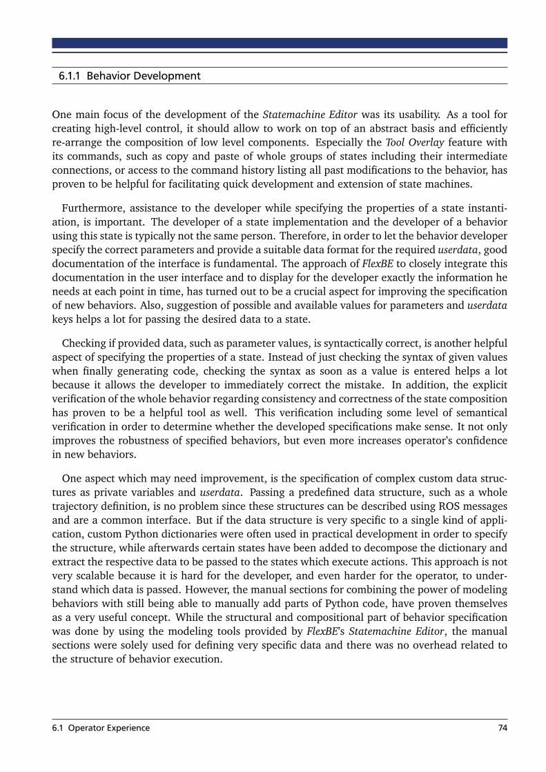
6.1.1 Behavior Development
One main focus of the development of the Statemachine Editor was its usability. As a tool forcreating high-level control, it should allow to work on top of an abstract basis and efficientlyre-arrange the composition of low level components. Especially the Tool Overlay feature withits commands, such as copy and paste of whole groups of states including their intermediateconnections, or access to the command history listing all past modifications to the behavior, hasproven to be helpful for facilitating quick development and extension of state machines.
Furthermore, assistance to the developer while specifying the properties of a state instanti-ation, is important. The developer of a state implementation and the developer of a behaviorusing this state is typically not the same person. Therefore, in order to let the behavior developerspecify the correct parameters and provide a suitable data format for the required userdata, gooddocumentation of the interface is fundamental. The approach of FlexBE to closely integrate thisdocumentation in the user interface and to display for the developer exactly the information heneeds at each point in time, has turned out to be a crucial aspect for improving the specificationof new behaviors. Also, suggestion of possible and available values for parameters and userdatakeys helps a lot for passing the desired data to a state.
Checking if provided data, such as parameter values, is syntactically correct, is another helpfulaspect of specifying the properties of a state. Instead of just checking the syntax of given valueswhen finally generating code, checking the syntax as soon as a value is entered helps a lotbecause it allows the developer to immediately correct the mistake. In addition, the explicitverification of the whole behavior regarding consistency and correctness of the state compositionhas proven to be a helpful tool as well. This verification including some level of semanticalverification in order to determine whether the developed specifications make sense. It not onlyimproves the robustness of specified behaviors, but even more increases operator’s confidencein new behaviors.
One aspect which may need improvement, is the specification of complex custom data struc-tures as private variables and userdata. Passing a predefined data structure, such as a wholetrajectory definition, is no problem since these structures can be described using ROS messagesand are a common interface. But if the data structure is very specific to a single kind of appli-cation, custom Python dictionaries were often used in practical development in order to specifythe structure, while afterwards certain states have been added to decompose the dictionary andextract the respective data to be passed to the states which execute actions. This approach is notvery scalable because it is hard for the developer, and even harder for the operator, to under-stand which data is passed. However, the manual sections for combining the power of modelingbehaviors with still being able to manually add parts of Python code, have proven themselvesas a very useful concept. While the structural and compositional part of behavior specificationwas done by using the modeling tools provided by FlexBE’s Statemachine Editor, the manualsections were solely used for defining very specific data and there was no overhead related tothe structure of behavior execution.
6.1 Operator Experience 74

6.1.2 Behavior Execution
As shown by previous practical experience, a focus on the currently active state is very importantwhen monitoring the execution of a behavior. For quickly understanding what the robot iscurrently doing, it is not sufficient to have a complete overview of the structure of the behaviorstate machine only, even when knowing which of the states is the active one. For this reason, theFlexBE has a special view, the Runtime Control, for monitoring behaviors during their execution.Similar to the previous user interface, the behavior control widget of FlorBE, the active stateand its outcomes are displayed. One problematic aspect of the previous user interface, however,was the limited amount of provided context, such as the previous state or consequences of eachdisplayed outcome. The new Runtime Control addresses this issue, as depicted in figure 6.1.This new approach has proven useful, along with the possibility to navigate in the hierarchy ofthe active state in order to view the current state of execution in different levels of abstraction.
The purpose of monitoring behavior execution is to give the operator the best possible esti-mation of what currently happens to the robot and what influences its next actions. Thus, it isnot enough to just monitor the currently active state in a behavior. However, since a behaviorrelies on existing low-level components for realizing the commanded actions, it turned out to bea scalable approach to rely on these external components to define their own way of monitor-ing, instead of trying to integrate everything, regardless of what is actually used by a particularbehavior. As a result, it is the goal of the behavior monitor to specifically monitor the controlflow of a behavior, providing insights on which components are currently relevant and how theyinteract with each other.
The commands which are sent by the operator are also closely tied to the control flow ofa behavior. Considering the circumstances of execution, especially the limited bandwidth anddelays causing a highly constrained communication, commands cannot be executed by the robotimmediately when commanded. Therefore, it is important that the operator is exactly aware ofwhich commands are currently pending and whether they can be executed as desired. This
(a) FlorBE
(b) FlexBE
Figure 6.1: Comparison of displaying the active state.
6.1 Operator Experience 75

issue is explicitly addressed by the RC.Snyc component of the Runtime Control in FlexBE. Thisapproach has proven as very effective for allowing comprehensive execution of commands.
Parametrization of behaviors and choosing appropriate values when starting one, is also ahelpful concept of behavior execution. But since behavior development is now much moreintegrated in FlexBE, a second way for configuring a behavior for execution has emerged. Insteadof using the behavior parameters for setting certain values, they were just provided as privateconfiguration variables and submitted as changes to the behavior source code. This is completelypossible, however, it is not the desired and modular way for providing these values. It turnedout that the reason for using the private configuration was to allow the entered values to besaved, and thus not need to set them again for each execution. Instead, behavior parameterscurrently have their default value for each execution unless changed. This shows that it willbe advantageous to save the last provided value to a parameter and to suggest it for the nextexecution instead of the default value. In addition, the operator can choose to go back to thedefault value at any time.
6.2 Behavior Performance
In order to evaluate the performance of behaviors as such, a State Logger has been implemented.This logger is integrated into the behavior engine and automatically logs each run of a behav-ior. During execution, one log entry is created each time the state machine takes a transition.The point in time of this transition and information on which outcome of which state has beenreturned are logged, as well as the implementation class of a state and if the transition has beentriggered autonomously or if it has been blocked. These log files can be evaluated afterwardsregarding different indicators, in order to measure the performance of various aspects of behav-ior execution. The user can specify a set of properties to be calculated, and regarding whichcriteria these properties should be accumulated.
An overview of available keys for properties and criteria is given in the appendix. This conceptof decoupled data recording and evaluation enables detailed information regarding multipleaspects of behavior performance even if these have not been specified before execution. Forexample, the accuracy with which the robot had correctly chosen a certain transition can becalculated, as well as the number of required operator interventions at a certain point in thebehavior, or the amount of time spent in a certain class of states.
Quantitative performance of behavior execution can be measured regarding efficiency andeffectiveness. Both aspects have been investigated by using a relatively simple and thus com-prehensible demo behavior inspired by the following scenario: A robot, in this case a simulatedATLAS v5 robot using Gazebo1, has the task to collect data regarding the environment in a dis-aster scenario. Its behavior is designed to iteratively walk a short distance and then take acamera image and send this data to the remote operator. However, during its mission, the robotenters a damaged building where the available light is insufficient for taking useful camera im-ages. At this point, the operator decides to modify the behavior during a walking phase of therobot in order to collect LIDAR scan data instead of camera images. The implementation of thisexploration behavior is given in the appendix.1 http://gazebosim.org/ (03/31/2015)
6.2 Behavior Performance 76

State Visits Intv Waiting Active
Init Radius 22 0 0.000 0.510
Calculate Next Pose 22 0 0.000 1.053
Determine Waypoint Valid 22 0 0.000 0.447
Plan To Waypoint 22 0 0.000 0.441
Perform Walking 22 1 0.000 561.672
Take Camera Image 16 0 0.000 1.443
Take Laser Scan 6 0 0.000 0.846
Send Image To Operator 22 0 0.000 11.530
Check Finished 22 1 2.316 3.901
Figure 6.2: Evaluation of the State Logger log file of the exploration behavior.
An evaluation of this demo mission is provided in figure 6.2. For each state, the amountof state executions (Visits), the amount of interventions (Intv), the time in seconds spent withwaiting for the operator (Waiting), and the total time in seconds this state has been the activestate during execution (Active), is listed. The intervention and waiting time in the Check Finishedstate results from ending the behavior. In order to keep the behavior from taking anotheriteration, the operator lowered the Autonomy Level and rejected the suggested transition whileinstead forcing the transition to return the finished outcome of the behavior.
As indicated by the amount of state visits, 22 iterations have been executed. After taking 16camera images, the behavior has been modified by the operator and the Take Camera Imagestate has been replaced by the Take Laser Scan for the remaining six iterations. Although thisis the log file for a single behavior execution, both, the camera image and the laser scan state,are listed although they only existed in different versions of this behavior. This way of modify-ing the behavior during its execution without the need for restarting it has proven to be veryefficient. Restarting the behavior would have required significantly more time, especially whenconsidering that specifying this modification could have taken much more time without use of abehavior framework built for making quick and safe changes, and that the new behavior wouldhave needed to be somehow transfered to the remote robot.
Regarding efficiency it is even more remarkable that the behavior modification did not at allcause the robot to wait for the operator and pause its own execution. As indicated by the logfile, the modification has taken place while the robot was walking to its next position. Since thisstate has been active for most of the time anyway, it is a good point in execution to be lockedin order to allow runtime modifications. While the state was locked, the robot kept walking.But in case that specifying the modifications would have taken longer than the robot walks, therobot would have waited before continuing its behavior execution.
Furthermore, the available partial semantic verification of behavior specifications has provenuseful as well to prevent task failure in this context. When the operator removed the Take Cam-era Image state and added the Take Laser Scan state, he forgot that the Send Image To Operatorstate still referred to the userdata key provided by the camera state. After the verification checkdisplayed an error message in order to tell the operator that the expected camera userdata is
6.2 Behavior Performance 77
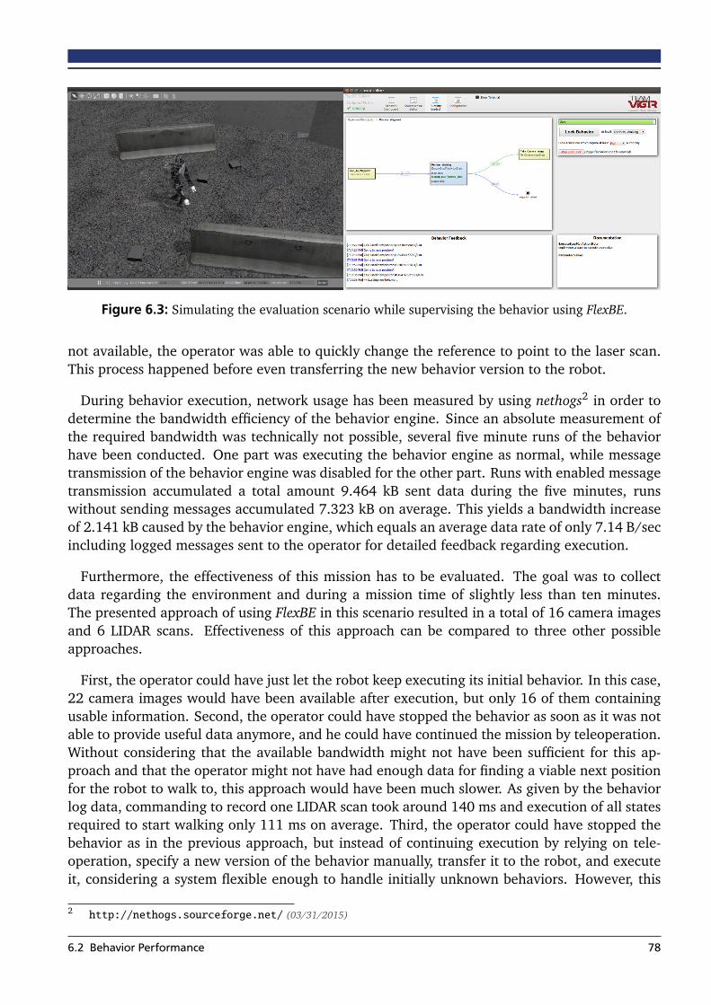
Figure 6.3: Simulating the evaluation scenario while supervising the behavior using FlexBE.
not available, the operator was able to quickly change the reference to point to the laser scan.This process happened before even transferring the new behavior version to the robot.
During behavior execution, network usage has been measured by using nethogs2 in order todetermine the bandwidth efficiency of the behavior engine. Since an absolute measurement ofthe required bandwidth was technically not possible, several five minute runs of the behaviorhave been conducted. One part was executing the behavior engine as normal, while messagetransmission of the behavior engine was disabled for the other part. Runs with enabled messagetransmission accumulated a total amount 9.464 kB sent data during the five minutes, runswithout sending messages accumulated 7.323 kB on average. This yields a bandwidth increaseof 2.141 kB caused by the behavior engine, which equals an average data rate of only 7.14 B/secincluding logged messages sent to the operator for detailed feedback regarding execution.
Furthermore, the effectiveness of this mission has to be evaluated. The goal was to collectdata regarding the environment and during a mission time of slightly less than ten minutes.The presented approach of using FlexBE in this scenario resulted in a total of 16 camera imagesand 6 LIDAR scans. Effectiveness of this approach can be compared to three other possibleapproaches.
First, the operator could have just let the robot keep executing its initial behavior. In this case,22 camera images would have been available after execution, but only 16 of them containingusable information. Second, the operator could have stopped the behavior as soon as it was notable to provide useful data anymore, and he could have continued the mission by teleoperation.Without considering that the available bandwidth might not have been sufficient for this ap-proach and that the operator might not have had enough data for finding a viable next positionfor the robot to walk to, this approach would have been much slower. As given by the behaviorlog data, commanding to record one LIDAR scan took around 140 ms and execution of all statesrequired to start walking only 111 ms on average. Third, the operator could have stopped thebehavior as in the previous approach, but instead of continuing execution by relying on tele-operation, specify a new version of the behavior manually, transfer it to the robot, and executeit, considering a system flexible enough to handle initially unknown behaviors. However, this
2 http://nethogs.sourceforge.net/ (03/31/2015)
6.2 Behavior Performance 78

approach would have required much more time until the new behavior would have been ableto start execution and thus, it is not really applicable in such a short mission.
In summary, the novel approach taken in the given scenario, now available due to the workpresented in this thesis, showed a good task performance and allowed for interruption-free taskexecution although a significant and unforeseen disturbance regarding the expected circum-stances occurred. Considering a more complex scenario than the one chosen for a meaningfulevaluation, as well as highly limited communication and further restrictions in direct controlof the robot, modifying a behavior in the way developed in this thesis and provided by FlexBEmight be, so far, the only option to prevent task failure.
6.3 DARPA Robotics Challenge
Main purpose of this thesis and the development of the FlexBE behavior framework is its ap-plication in the DARPA Robotics Challenge, in order to provide the robot the ability to semi-autonomously make decisions and to autonomously execute high-level commands. In prepara-tion for the DRC Finals, a lot of states and a set of behaviors have been developed using FlexBE.The developed states interface with the rest of the team’s software and include states for foot-step planning and execution, endeffector motions, grasping, and changing internal parameters.A full list of states is provided in the appendix.
Until the submission date of this thesis, the team’s ATLAS robot had some technical issuespreventing it from executing complex actions. For this reason, testing of developed behaviorsmostly took place in simulation. Nevertheless, behaviors have been developed and preparedfor execution. An excerpt of a developed behavior is given in figures 6.4 and 6.5. In this part,the robot is supposed to walk near an object of interest which should be grasped afterwards.The object is specified by the operator, based on the perception of the robot, as a template.Thereafter, the robot is able to extract several data, such as a viable position to stand in orderto grasp the specified object, from this template by leveraging the template server. Based on
Figure 6.4: Behavior to walk near an object of interest.
6.3 DARPA Robotics Challenge 79
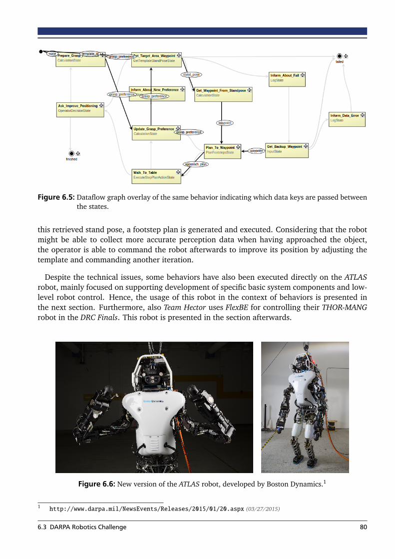
Figure 6.5: Dataflow graph overlay of the same behavior indicating which data keys are passed betweenthe states.
this retrieved stand pose, a footstep plan is generated and executed. Considering that the robotmight be able to collect more accurate perception data when having approached the object,the operator is able to command the robot afterwards to improve its position by adjusting thetemplate and commanding another iteration.
Despite the technical issues, some behaviors have also been executed directly on the ATLASrobot, mainly focused on supporting development of specific basic system components and low-level robot control. Hence, the usage of this robot in the context of behaviors is presented inthe next section. Furthermore, also Team Hector uses FlexBE for controlling their THOR-MANGrobot in the DRC Finals. This robot is presented in the section afterwards.
Figure 6.6: New version of the ATLAS robot, developed by Boston Dynamics.1
1 http://www.darpa.mil/NewsEvents/Releases/2015/01/20.aspx (03/27/2015)
6.3 DARPA Robotics Challenge 80

6.3.1 ATLAS
The ATLAS robot has been developed by Boston Dynamics and funded by DARPA. Figure 6.6shows the latest currently available version of the robot. Compared to the previous version ofthis robot, around 75% of the parts are exchanged or improved in the new ATLAS v5. Deviantfrom figure 6.6, the final ATLAS v5 includes electric forearms, containing an additional joint.Thus, the arms of ATLAS v5 have seven degrees of freedom each, providing much better manip-ulation capabilities. All in all, the robot now has 30 joints, most of these hydraulically actuated,a size of 1.88 meters, and a weight of 157 kilograms.
Main goal of the upgrades to ATLAS was to remove the need for a wired connection to therobot. Instead of relying on an external pump for actuating the hydraulic joints, the robotnow has an energy-efficient and quiet variable pressure pump built-in. Furthermore, a wirelessrouter integrated in the head of the robot supersedes the need for wired communication and abattery with a capacity of 3.7 kilowatt hours provides enough energy for roughly one hour ofmixed operation, including walking and manipulation.
During the development phase prior to the competition, main focus of behaviors was to sup-port the development of different parts of the system, foremost by automating tests in order todetermine specific properties of the robot. For this purpose, a system identification behavior hasbeen implemented. This behavior loads defined trajectories, coordinates and automates theirexecution, and records all required data such as commanded and actual joint values includingvideo recordings of all experiments. During an experiment, the operator always has the possi-bility to let the behavior run in full autonomy, or to reduce the Autonomy Level at certain pointswhen executing rather risky trajectories or parameter settings.
(a) (b)
Figure 6.7: Testing with the robot: (a) ready for system identification, (b) testing simple grasping.
6.3 DARPA Robotics Challenge 81

In total, several hours of pure execution time of this system identification behavior accumu-lated, testing more than one hundred single trajectories with different settings and proving therobustness and applicability of FlexBE along with such a complex system as the ATLAS robot.Furthermore, development and operation of the resulting behavior have been made by differ-ent persons, providing a great opportunity for evaluation of FlexBE and for improving certainaspects.
Another behavior executed on the robot is the so-called Praying Mantis behavior. This be-havior commands the joints to go near their respective limits and then commands the low-levelcontroller of each joint to carefully push beyond these limits while monitoring the actual jointpositions. This allows to determine joint offsets of the robot and to calibrate the joints for morereliable execution of motions afterwards. Executing this behavior in full autonomy each timethe robot is started provides an easy and effective way for always having a calibrated robotwithout the need for manual calibration and for defining static offsets in a configuration file.
6.3.2 THOR-MANG
The THOR-MANG is a humanoid robot platform developed in a collaboration between Robotis3,Virginia Tech4, the University of Pennsylvania5, and Harris Corporation6. The robot consists of30 electrically actuated joints based on Robotis’ Dynamixel PRO servomotors, is 1.47 meters talland weighs 49 kilograms. This robot is used by a cooperation between Team Hector and TeamViGIR to demonstrate the applicability of the software developed by Team ViGIR not only for anATLAS robot, but also for further robots such as THOR-MANG.
(a) (b) (c)
Figure 6.8: THOR-MANG robot platform, (a) and (b) taken from [27].
3 http://www.robotis.com/ (03/31/2015)4 http://www.romela.org/ (03/31/2015)5 https://www.grasp.upenn.edu/ (03/31/2015)6 http://harris.com/ (03/31/2015)
6.3 DARPA Robotics Challenge 82
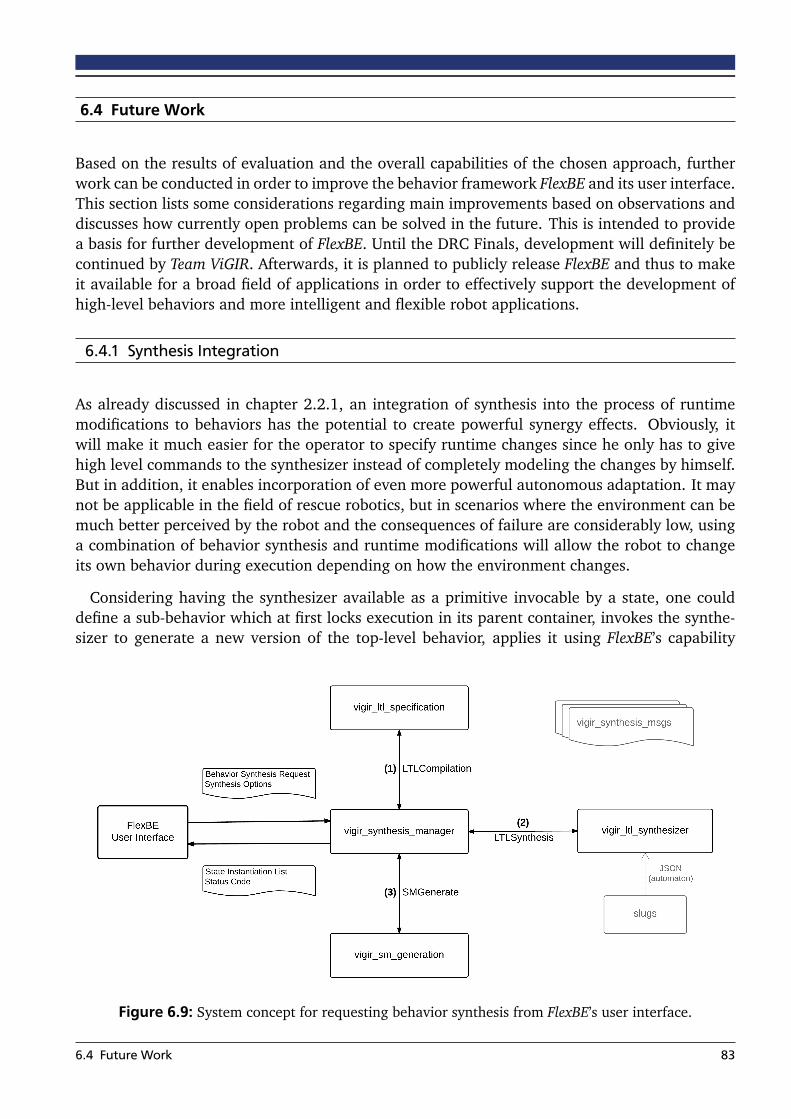
6.4 Future Work
Based on the results of evaluation and the overall capabilities of the chosen approach, furtherwork can be conducted in order to improve the behavior framework FlexBE and its user interface.This section lists some considerations regarding main improvements based on observations anddiscusses how currently open problems can be solved in the future. This is intended to providea basis for further development of FlexBE. Until the DRC Finals, development will definitely becontinued by Team ViGIR. Afterwards, it is planned to publicly release FlexBE and thus to makeit available for a broad field of applications in order to effectively support the development ofhigh-level behaviors and more intelligent and flexible robot applications.
6.4.1 Synthesis Integration
As already discussed in chapter 2.2.1, an integration of synthesis into the process of runtimemodifications to behaviors has the potential to create powerful synergy effects. Obviously, itwill make it much easier for the operator to specify runtime changes since he only has to givehigh level commands to the synthesizer instead of completely modeling the changes by himself.But in addition, it enables incorporation of even more powerful autonomous adaptation. It maynot be applicable in the field of rescue robotics, but in scenarios where the environment can bemuch better perceived by the robot and the consequences of failure are considerably low, usinga combination of behavior synthesis and runtime modifications will allow the robot to changeits own behavior during execution depending on how the environment changes.
Considering having the synthesizer available as a primitive invocable by a state, one coulddefine a sub-behavior which at first locks execution in its parent container, invokes the synthe-sizer to generate a new version of the top-level behavior, applies it using FlexBE’s capability
Figure 6.9: System concept for requesting behavior synthesis from FlexBE’s user interface.
6.4 Future Work 83

for runtime modifications, and finally continues execution by now using the new version. Thissub-behavior can be embedded into any other behavior, and be invoked as soon as a differencein the environment is detected. Synthesis of the new behavior will not be restricted in any waysince the new version will still contain the synthesis sub-behavior which is the pivot state of thisswitch. This whole process can finally be combined with approaches on machine learning inorder to optimize situational adaption of robot behaviors.
While this way of combining synthesis and runtime modifications is rather a long-term objec-tive, supporting operator and developer by using synthesis for more efficient behavior definitionis really a practical extension to the framework as it is now. It is currently developed togetherwith the Verifiable Robotics Research Group at Cornell University. It is planned that the developerwill not have to start with an empty state machine when starting to create a new behavior ornew parts of an existing behavior. Instead, he can provide a set of high-level initial conditionsand goals to be achieved by this part of the behavior. Behavior synthesis will then draft a firstversion of a possible behavior to achieve these goals, which can be modified and extended bythe developer afterwards.
This development can be seen as a first step towards combining FlexBE with behavior synthe-sis. More advanced integration can then actively assist the developer when specifying behaviorsmanually by relying on the state constraints defined in chapter 3.5. For example, when thedeveloper adds a new state to the behavior and connects it in a way that its preconditions arenot fulfilled, required intermediate states can be synthesized and automatically added, insteadof just displaying an error message.
6.4.2 Web-based Solution
FlexBE not only incorporates a flexible behavior engine, but also a very flexible user interfaceby relying on HTML and JavaScript. In general, it would be possible to run the user interface asa web app, removing the need for installing any software locally and being platform indepen-dent. This means, that the operator would actually be able to control the robot even with hissmartphone or a tablet. However, there are currently two aspects limiting this form of usage.
First, the user interface requires native file system access for parsing available states andbehaviors, as well as generating source code and creating ROS packages for new behaviors.This is currently realized by implementing the user interface as a Google Chrome App, dependingon Google Chrome to be available and requiring the user to install the app. Second, for actuallyexecuting behaviors, a connection to ROS is required. While this is possible without using GoogleChrome, it is inevitable to have Rosbridge running on a Linux machine. Eliminating both of thesetwo needs is the prerequisite for designing a web-based solution.
One feasible approach would be to rely on a central server. A simple development server sim-ilar to using common repositories for software development would already eliminate the needfor depending on Google Chrome and would enable to develop behaviors in any web browserwithout installing any software. The development server would store all developed states andbehaviors, and instead of accessing the local file system, the user interface client would justcommunicate with the server. However, this solution would still require a Linux-based operat-ing system running ROS and Rosbridge to create a connection with the ROS network.
6.4 Future Work 84

(a) Web client connected to the robot (b) Remote web client
Figure 6.10: Possible concepts for server integration.
Instead of just having a remote server as development repository for defined states and be-haviors, it is also possible to have a server with access to the ROS network of the robot. Thisserver could even be executed as a local ROS node when working on a Linux machine. Insteadof communicating directly with ROS from the user interface based on Rosbridge, the user inter-face would communicate instead with the server, which is then able to send and receive localmessages in the ROS network of the robot. This would eliminate all dependencies on Linux andeven Rosbridge and thus enable a completely remote operation from any device, possibly evenvia the internet.
6.4.3 Parallel Execution
Right now, FlexBE is designed to support only one active state at a given point in time. This stateis centered in the Runtime Control view and the operator can send commands directly influenc-ing its execution. However, in some cases, being able to execute multiple states at the same timewould be helpful. In order to provide a first solution for these scenarios, the ConcurrentStatehas been added, allowing parallel execution of states. While this adds everything required froman execution-point of view, it does not provide the same operator integration as known fromFlexBE.
The ConcurrentState is just a common state and thus, its internal functionality is transparentto FlexBE. When this state is executed, it is displayed as the sole currently active state, no matterwhich states or even state machines are executed internally. For this reason, further work canbe done to better integrate concurrency and parallel execution into the user interface and thecommunication protocol of FlexBE. However, this will require some fundamental changes of theconcept since there will be for example no single pivot state. Also verification will be muchmore complex when having to account for interdependencies between possibly simultaneouslyrunning states.
6.4 Future Work 85

6.4.4 Multiple Robots
In future, more advanced robotic rescue missions will most likely involve multiple robots. Inthis context, it is important to note that FlexBE itself is not limited to controlling a single robot.It rather can be seen in a way that FlexBE is controlling a system. In current applications, aspresented in the previous part of this chapter, the system relies on a single robot to execute thespecified actions. But there is no restriction that the system cannot utilize the capabilities of twoor more robots as well in order to execute the commanded actions.
Nevertheless, practical applications in multi-robot systems will likely need some additionalfeatures. The most important feature in this context, for sure, is the ability to execute states inparallel when sticking to the approach of central coordination of the agents of this system. Ifchoosing an approach where each agent forms a sub-system and is controlled decentralized byrunning its own instance of FlexBE, it should be possible to use different ROS namespaces toindependently control each robot. However, each robot would have its own user interface thisway. This may be intended in some cases, but may not in other cases. A solution to controlmultiple instances of onboard behavior engines with a single, central instance of FlexBE wouldbe a helpful feature in this context.
6.4 Future Work 86

7 Conclusion
This thesis presents an approach for realizing modifications to high-level behavior control evenwhile the robot is running, controlled by this behavior itself. Furthermore, the operator is con-sidered as an important factor for both, monitoring behavior execution and specifying requiredmodifications, and thus, is tightly integrated in the system. This approach enables applicationof the developed system in a variety of scenarios, even without detailed knowledge in advanceabout the environment and how the desired goal can be achieved.
Main focus of this thesis is the application in the field of rescue robotics, using advanced hu-manoid robots for combining capabilities such as dexterous manipulation and navigation acrossrough terrain. Efficient performance of robots is considerably impeded by the unstructuredenvironment in typical disaster mitigation scenarios. Designing a complete, specific high-levelbehavior control approach in advance is not possible, considering the limited a priori knowledgeand the rather complex system. Furthermore, the ability to communicate with the remote robotis severely limited and failure of task execution has to be considered very carefully.
The presented approach models behaviors as hierarchical state machines. Single states corre-spond to actions that are performed by the robot in order to get one step closer to the desiredtask goal. Transitions to next states are taken depending on the result of execution, allowingto create robust behaviors accounting for various kinds of failure. This approach abstracts verywell from task-specific details and provides a widely applicable basis for high-level decisionsand coordination between multiple, otherwise independent components of complex systems.Behavior modifications can be realized on the level of state composition, enabling to clearlyidentify parts which are safe to be modified and to apply verification checks to greatly reducethe risk of runtime failure.
Furthermore, this thesis includes implementation of the developed concepts. The resulting be-havior engine, FlexBE, not only targets execution of behaviors based on the discussed concepts,but rather incorporates a fully practically applicable software environment for developing, exe-cuting, monitoring, and modifying behaviors. Worth mentioning is the included user interface,carefully designed for both expert and non-expert users and allowing to effectively abstract fromlow-level details while giving accurate feedback on behavior execution. By utilizing powerfulsynchronization concepts such as mirroring behaviors, bandwidth usage is still kept very low.
In summary, this thesis contributes to the development of more intelligent and complex robots,especially in an unstructured and hardly accessible environment. This is done by providing thecapability to flexibly adapt the high-level behavior of the remote robot and effectively integratingcooperation with the operator. Specification of new behaviors and behavior modifications areassisted by an editor which also includes partial semantic behavior verification and guaranteesgeneration of a syntactically correct implementation of the specification.
Finally, the results of this thesis are applied by Team ViGIR and Team Hector in the interna-tional DARPA Robotics Challenge, competing along with some of the most recent and advancedrescue robotics research efforts. FlexBE has already been used by Team ViGIR for running system
87
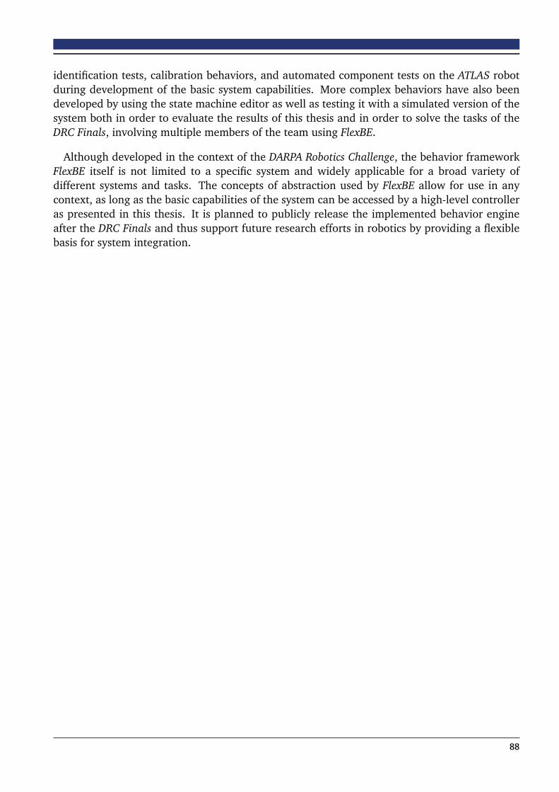
identification tests, calibration behaviors, and automated component tests on the ATLAS robotduring development of the basic system capabilities. More complex behaviors have also beendeveloped by using the state machine editor as well as testing it with a simulated version of thesystem both in order to evaluate the results of this thesis and in order to solve the tasks of theDRC Finals, involving multiple members of the team using FlexBE.
Although developed in the context of the DARPA Robotics Challenge, the behavior frameworkFlexBE itself is not limited to a specific system and widely applicable for a broad variety ofdifferent systems and tasks. The concepts of abstraction used by FlexBE allow for use in anycontext, as long as the basic capabilities of the system can be accessed by a high-level controlleras presented in this thesis. It is planned to publicly release the implemented behavior engineafter the DRC Finals and thus support future research efforts in robotics by providing a flexiblebasis for system integration.
88
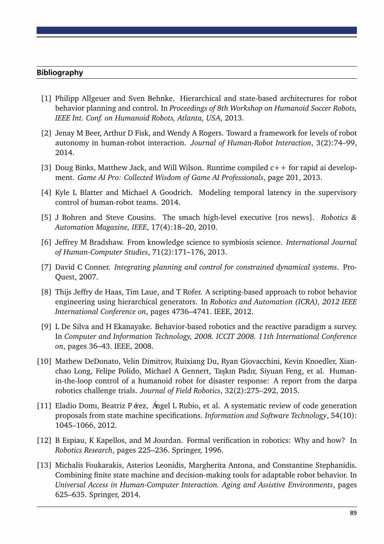
Bibliography
[1] Philipp Allgeuer and Sven Behnke. Hierarchical and state-based architectures for robotbehavior planning and control. In Proceedings of 8th Workshop on Humanoid Soccer Robots,IEEE Int. Conf. on Humanoid Robots, Atlanta, USA, 2013.
[2] Jenay M Beer, Arthur D Fisk, and Wendy A Rogers. Toward a framework for levels of robotautonomy in human-robot interaction. Journal of Human-Robot Interaction, 3(2):74–99,2014.
[3] Doug Binks, Matthew Jack, and Will Wilson. Runtime compiled c++ for rapid ai develop-ment. Game AI Pro: Collected Wisdom of Game AI Professionals, page 201, 2013.
[4] Kyle L Blatter and Michael A Goodrich. Modeling temporal latency in the supervisorycontrol of human-robot teams. 2014.
[5] J Bohren and Steve Cousins. The smach high-level executive [ros news]. Robotics &Automation Magazine, IEEE, 17(4):18–20, 2010.
[6] Jeffrey M Bradshaw. From knowledge science to symbiosis science. International Journalof Human-Computer Studies, 71(2):171–176, 2013.
[7] David C Conner. Integrating planning and control for constrained dynamical systems. Pro-Quest, 2007.
[8] Thijs Jeffry de Haas, Tim Laue, and T Rofer. A scripting-based approach to robot behaviorengineering using hierarchical generators. In Robotics and Automation (ICRA), 2012 IEEEInternational Conference on, pages 4736–4741. IEEE, 2012.
[9] L De Silva and H Ekanayake. Behavior-based robotics and the reactive paradigm a survey.In Computer and Information Technology, 2008. ICCIT 2008. 11th International Conferenceon, pages 36–43. IEEE, 2008.
[10] Mathew DeDonato, Velin Dimitrov, Ruixiang Du, Ryan Giovacchini, Kevin Knoedler, Xian-chao Long, Felipe Polido, Michael A Gennert, Taskın Padır, Siyuan Feng, et al. Human-in-the-loop control of a humanoid robot for disaster response: A report from the darparobotics challenge trials. Journal of Field Robotics, 32(2):275–292, 2015.
[11] Eladio Domı, Beatriz Pérez, Ángel L Rubio, et al. A systematic review of code generationproposals from state machine specifications. Information and Software Technology, 54(10):1045–1066, 2012.
[12] B Espiau, K Kapellos, and M Jourdan. Formal verification in robotics: Why and how? InRobotics Research, pages 225–236. Springer, 1996.
[13] Michalis Foukarakis, Asterios Leonidis, Margherita Antona, and Constantine Stephanidis.Combining finite state machine and decision-making tools for adaptable robot behavior. InUniversal Access in Human-Computer Interaction. Aging and Assistive Environments, pages625–635. Springer, 2014.
89
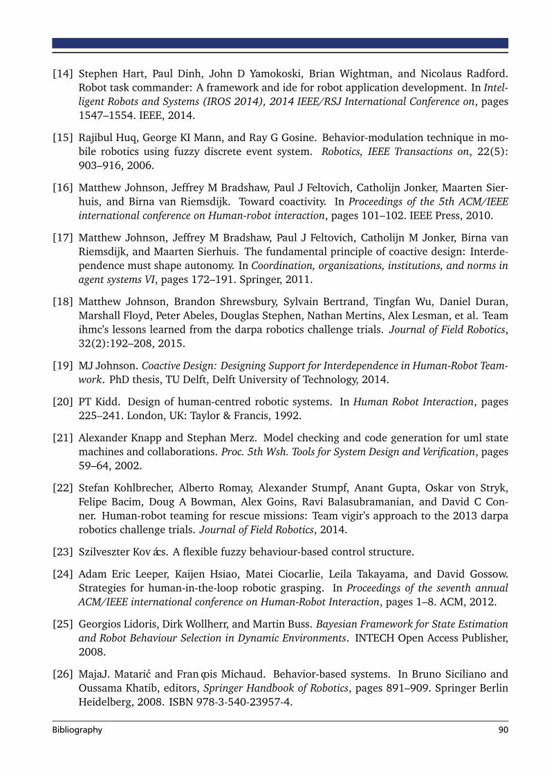
[14] Stephen Hart, Paul Dinh, John D Yamokoski, Brian Wightman, and Nicolaus Radford.Robot task commander: A framework and ide for robot application development. In Intel-ligent Robots and Systems (IROS 2014), 2014 IEEE/RSJ International Conference on, pages1547–1554. IEEE, 2014.
[15] Rajibul Huq, George KI Mann, and Ray G Gosine. Behavior-modulation technique in mo-bile robotics using fuzzy discrete event system. Robotics, IEEE Transactions on, 22(5):903–916, 2006.
[16] Matthew Johnson, Jeffrey M Bradshaw, Paul J Feltovich, Catholijn Jonker, Maarten Sier-huis, and Birna van Riemsdijk. Toward coactivity. In Proceedings of the 5th ACM/IEEEinternational conference on Human-robot interaction, pages 101–102. IEEE Press, 2010.
[17] Matthew Johnson, Jeffrey M Bradshaw, Paul J Feltovich, Catholijn M Jonker, Birna vanRiemsdijk, and Maarten Sierhuis. The fundamental principle of coactive design: Interde-pendence must shape autonomy. In Coordination, organizations, institutions, and norms inagent systems VI, pages 172–191. Springer, 2011.
[18] Matthew Johnson, Brandon Shrewsbury, Sylvain Bertrand, Tingfan Wu, Daniel Duran,Marshall Floyd, Peter Abeles, Douglas Stephen, Nathan Mertins, Alex Lesman, et al. Teamihmc’s lessons learned from the darpa robotics challenge trials. Journal of Field Robotics,32(2):192–208, 2015.
[19] MJ Johnson. Coactive Design: Designing Support for Interdependence in Human-Robot Team-work. PhD thesis, TU Delft, Delft University of Technology, 2014.
[20] PT Kidd. Design of human-centred robotic systems. In Human Robot Interaction, pages225–241. London, UK: Taylor & Francis, 1992.
[21] Alexander Knapp and Stephan Merz. Model checking and code generation for uml statemachines and collaborations. Proc. 5th Wsh. Tools for System Design and Verification, pages59–64, 2002.
[22] Stefan Kohlbrecher, Alberto Romay, Alexander Stumpf, Anant Gupta, Oskar von Stryk,Felipe Bacim, Doug A Bowman, Alex Goins, Ravi Balasubramanian, and David C Con-ner. Human-robot teaming for rescue missions: Team vigir’s approach to the 2013 darparobotics challenge trials. Journal of Field Robotics, 2014.
[23] Szilveszter Kovács. A flexible fuzzy behaviour-based control structure.
[24] Adam Eric Leeper, Kaijen Hsiao, Matei Ciocarlie, Leila Takayama, and David Gossow.Strategies for human-in-the-loop robotic grasping. In Proceedings of the seventh annualACM/IEEE international conference on Human-Robot Interaction, pages 1–8. ACM, 2012.
[25] Georgios Lidoris, Dirk Wollherr, and Martin Buss. Bayesian Framework for State Estimationand Robot Behaviour Selection in Dynamic Environments. INTECH Open Access Publisher,2008.
[26] MajaJ. Mataric and François Michaud. Behavior-based systems. In Bruno Siciliano andOussama Khatib, editors, Springer Handbook of Robotics, pages 891–909. Springer BerlinHeidelberg, 2008. ISBN 978-3-540-23957-4.
Bibliography 90
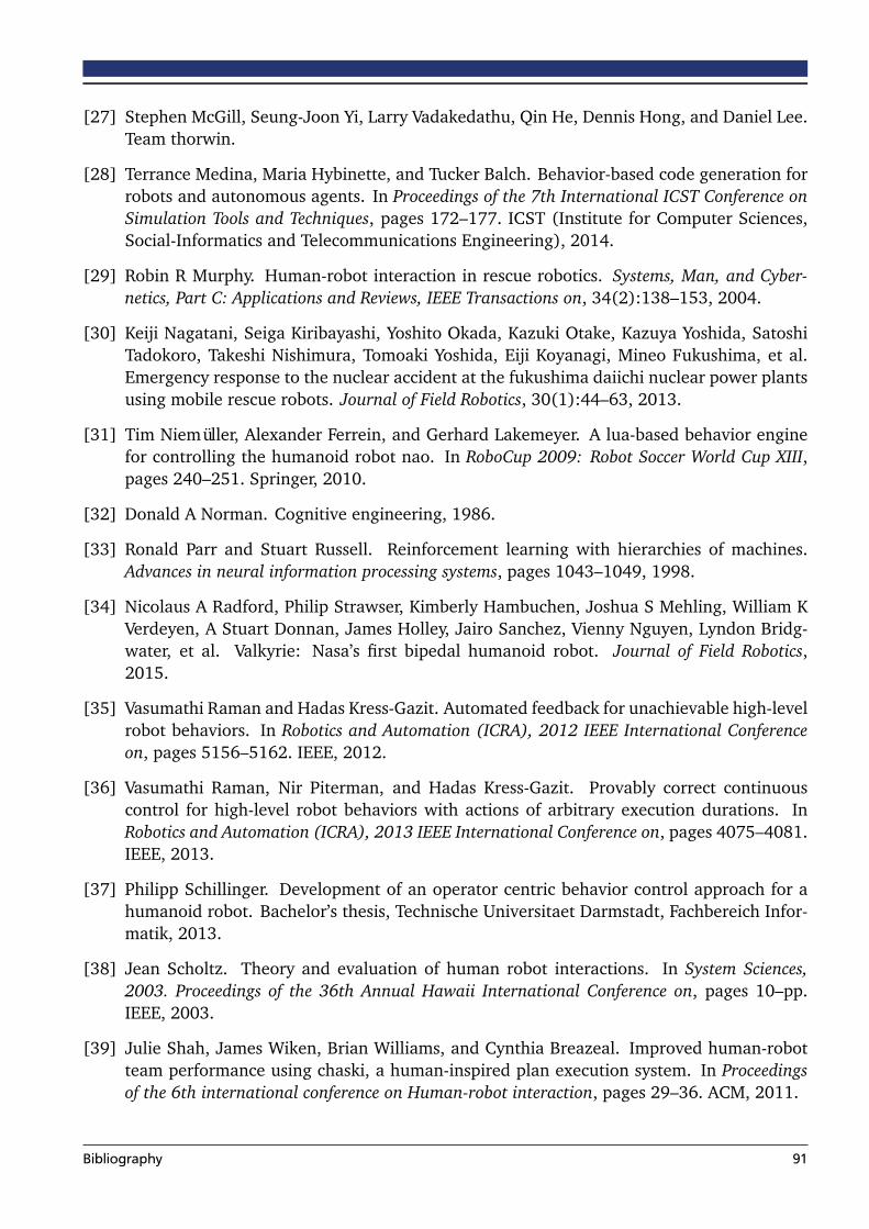
[27] Stephen McGill, Seung-Joon Yi, Larry Vadakedathu, Qin He, Dennis Hong, and Daniel Lee.Team thorwin.
[28] Terrance Medina, Maria Hybinette, and Tucker Balch. Behavior-based code generation forrobots and autonomous agents. In Proceedings of the 7th International ICST Conference onSimulation Tools and Techniques, pages 172–177. ICST (Institute for Computer Sciences,Social-Informatics and Telecommunications Engineering), 2014.
[29] Robin R Murphy. Human-robot interaction in rescue robotics. Systems, Man, and Cyber-netics, Part C: Applications and Reviews, IEEE Transactions on, 34(2):138–153, 2004.
[30] Keiji Nagatani, Seiga Kiribayashi, Yoshito Okada, Kazuki Otake, Kazuya Yoshida, SatoshiTadokoro, Takeshi Nishimura, Tomoaki Yoshida, Eiji Koyanagi, Mineo Fukushima, et al.Emergency response to the nuclear accident at the fukushima daiichi nuclear power plantsusing mobile rescue robots. Journal of Field Robotics, 30(1):44–63, 2013.
[31] Tim Niemüller, Alexander Ferrein, and Gerhard Lakemeyer. A lua-based behavior enginefor controlling the humanoid robot nao. In RoboCup 2009: Robot Soccer World Cup XIII,pages 240–251. Springer, 2010.
[32] Donald A Norman. Cognitive engineering, 1986.
[33] Ronald Parr and Stuart Russell. Reinforcement learning with hierarchies of machines.Advances in neural information processing systems, pages 1043–1049, 1998.
[34] Nicolaus A Radford, Philip Strawser, Kimberly Hambuchen, Joshua S Mehling, William KVerdeyen, A Stuart Donnan, James Holley, Jairo Sanchez, Vienny Nguyen, Lyndon Bridg-water, et al. Valkyrie: Nasa’s first bipedal humanoid robot. Journal of Field Robotics,2015.
[35] Vasumathi Raman and Hadas Kress-Gazit. Automated feedback for unachievable high-levelrobot behaviors. In Robotics and Automation (ICRA), 2012 IEEE International Conferenceon, pages 5156–5162. IEEE, 2012.
[36] Vasumathi Raman, Nir Piterman, and Hadas Kress-Gazit. Provably correct continuouscontrol for high-level robot behaviors with actions of arbitrary execution durations. InRobotics and Automation (ICRA), 2013 IEEE International Conference on, pages 4075–4081.IEEE, 2013.
[37] Philipp Schillinger. Development of an operator centric behavior control approach for ahumanoid robot. Bachelor’s thesis, Technische Universitaet Darmstadt, Fachbereich Infor-matik, 2013.
[38] Jean Scholtz. Theory and evaluation of human robot interactions. In System Sciences,2003. Proceedings of the 36th Annual Hawaii International Conference on, pages 10–pp.IEEE, 2003.
[39] Julie Shah, James Wiken, Brian Williams, and Cynthia Breazeal. Improved human-robotteam performance using chaski, a human-inspired plan execution system. In Proceedingsof the 6th international conference on Human-robot interaction, pages 29–36. ACM, 2011.
Bibliography 91

[40] Aaron Steinfeld, Terrence Fong, David Kaber, Michael Lewis, Jean Scholtz, Alan Schultz,and Michael Goodrich. Common metrics for human-robot interaction. In Proceedings ofthe 1st ACM SIGCHI/SIGART conference on Human-robot interaction, pages 33–40. ACM,2006.
[41] Fernando Trasvina, Eric Shepherd, et al. Introduction to Object-Oriented JavaScript.https://developer.mozilla.org/en-US/docs/Web/JavaScript/Introduction_to_
Object-Oriented_JavaScript, 2007. [Online; accessed 19-March-2015].
[42] Eiji Uchibe, Minoru Asada, and Koh Hosoda. Behavior coordination for a mobile robotusing modular reinforcement learning. In Intelligent Robots and Systems’ 96, IROS 96,Proceedings of the 1996 IEEE/RSJ International Conference on, volume 3, pages 1329–1336.IEEE, 1996.
[43] Holly A Yanco, Adam Norton, Willard Ober, David Shane, Anna Skinner, and Jack Vice.Analysis of human-robot interaction at the darpa robotics challenge trials. Journal of FieldRobotics, 2015.
[44] Matt Zucker, Sungmoon Joo, Michael X Grey, Christopher Rasmussen, Eric Huang, MichaelStilman, and Aaron Bobick. A general-purpose system for teleoperation of the drc-hubohumanoid robot. Journal of Field Robotics, 2015.
Bibliography 92

Appendix

A.1 List of Developed States
The following tables list all state implementations currently available in FlexBE. The states aresplit into different packages regarding the system they can be used with. All states with noexternal dependencies are part of the flexbe_states package and can be used along withany system. Further states have been developed to be used with ATLAS and the Team ViGIRsoftware, these are listed in the flexbe_atlas_states. However, although developed to beused with ATLAS, they can also be used with THOR-MANG in conjuction with the Team ViGIRsoftware. A more detailed documentation including the interface of each state is available inthe FlexBE Statemachine Editor or in the source code of each state.
A.1.1 flexbe_states
State Class Description
CalculationState Implements a state that can perform a calculation based onuserdata. The calculation is a function which takes exactly oneparameter, input_value from userdata, and its return value isstored in output_value after leaving the state.
CheckConditionState Checks if the given condition is true and returns the corre-sponding outcome. This state can be used if the further controlflow of the behavior depends on a simple condition.
ConcurrentState Implements concurrent execution of states. Depending on theoutcomes of the single states, the outcome of this state is de-termined according to the given set of rules.
DecisionState Evaluates a condition function in order to return one of thespecified outcomes. This state can be used if the further con-trol flow of the behavior depends on an advanced condition.
FlexibleCalculationState Implements a state that can perform a calculation based onmultiple userdata inputs provided as a list to the calculationfunction.
InputState Implements a state where the state machine needs an inputfrom the operator. Requests of different types, such as request-ing a waypoint, a template, or a pose, can be specified.
LogState A state that can log a predefined message to precisely informthe operator about what happened to the behavior.
OperatorDecisionState Implements a state where the operator has to choose an out-come manually. Autonomy Level of all outcomes should be setto Full, since this state is not able to choose an outcome onits own. Only exception is the suggested outcome, which willbe returned immediately by default. This state can be used tocreate alternative execution paths by setting the suggestion toHigh autonomy instead of Full.
94

StartRecordLogsState A state that records the contents of the specified ROS topicsin a bag file. Logging is done by creating a rosbag sub-process which is afterwards accessible using the output keyrosbag_process. This state is typically combined with a Sto-pRecordLogsState which gets the subprocess in order to stoplogging.
StopRecordLogsStates A state that records the contents of the specified ROS topics ina bag file.
WaitState Implements a state that can be used to wait on timed process.
A.1.2 flexbe_atlas_states
State Class Description
ChangeControlModeActionState Implements a state where the robot changes its con-trol mode using the action.
CheckCurrentControlModeState Implements a state where the robot checks its cur-rent control mode.
CurrentJointPositionsState Retrieves the current positions of the joints of thespecified planning group.
ExecuteStepPlanActionState Implements a state to execute a step plan of the foot-step planner. This state will change the control modeof the robot to STEP during execution and expects tobe in STAND when entered.
ExecuteTrajectoryBothArmsState Executes trajectory(ies) passed from userdata.
ExecuteTrajectoryMsgState Executes a given joint trajectory message.
ExecuteTrajectoryState Executes a custom trajectory.
FootstepPlanRealignCenterState Implements a state where the robot plans to centersits feet.
FootstepPlanRelativeState Implements a state where the robot plans a relativemotion, e.g., 2m to the left. Please note that the dis-tance is only approximate, actual distance dependson exact step alignment.
FootstepPlanTurnState Implements a state where the robot plans a motion toturn in place, e.g. 90 degree to the left. Please notethat the angle is only approximate, actual distancedepends on exact step alignment.
FootstepPlanWideStanceState Implements a state where the robot plans to moveinto wide stance.
GetCameraImageState Grabs the most recent camera image.
GetLaserscanState Grabs the most recent laserscan data.
GetTemplateGraspState Requests a grasp for a template from the templateserver.
95

GetTemplatePoseState Requests the pose of a template from the templateserver.
GetTemplatePregraspState Requests pregrasp information for a template fromthe template server.
GetTemplateStandPoseState Requests the pose where to stand in front of a tem-plate from the template server.
HandTrajectoryState Executes a given hand trajectory, i.e., a request toopen or close the fingers.
LoadTrajectoryFromBagfileState Implements a state that loads (arm) trajectoriesstored in a bagfile.
LocomotionPosePerceptionState Extracts a pose of interest to walk to from environ-ment data.
MotionServiceState Implements a state where a certain motion is per-formed. This state can be used to execute motionscreated by the motion editor.
MoveitCommanderMoveGroupState Uses moveit commander to plan to the given jointconfiguration and execute the resulting trajctory.
MoveItMoveGroupPlanState Employs moveit Move Group to get a plan to a goalconfiguration, but does not execute it.
MoveitMoveGroupState Uses moveit to plan to the given joint configurationand executes the resulting trajctory.
MoveitStartingPointState Uses moveit to plan and move to the first point of agiven arm trajectory.
PickupObjectState Uses moveit to perform a pickup action.
PlanEndeffectorCartesianState Plans a cartesian endeffector trajectory passing allgiven waypoints.
PlanEndeffectorCircularState Plans a circular motion of the endeffector.
PlanEndeffectorPoseState Plans to reach the given pose with the specified end-effector.
PlanFootstepsState Creates a footstep plan to reach the specified way-point from the current position.
ReadDynamicParameterState Reads a given trajectory controller parameter set.
SendToOperatorState Sends the provided data to the operator using ageneric serialized topic.
UpdateDynamicParameterState Updates a given trajectory controller parameter set.
UpdateJointCalibrationState Updates the calibration offsets for the given joints.
VideoLoggingState A state that controls video logging.
96

A.2 Evaluation of Behavior Logfiles
Each behavior execution automatically creates a new log file. Default location for these filesis the logs folder inside the home folder. Independently from executing a behavior, these logfiles can be evaluated in order to derive information about execution performance regardingvarious aspects. An example evaluation is given in chapter 6.2. The evaluation script can beexecuted by running:
rosrun flexbe_widget evaluate_logs [logfile] [key] [value1, value2, ...]
[logfile] can be used to specify any log file. It can also be set to an empty string which willresult in using the most recent log file in the default folder.
[key] refers to one of the choices listed in the table below and is used to accumulate the dataof the single log entries in order to evaluate regarding specific categories.
Keys for Accumulation
total Accumulates all entries.
state_path Uses the unique path of a state.
state_name The name of each state is the keys, can be ambiguous.
state_class Accumulate entries according to their implementation.
transition Each transition is evaluated separately.
[value1, value2, ...] is any combination of the available indicators as listed below. Eachof these indicators can be derived from the logged data and will be accumulated accordingto the specified key.
Available Performance Indicators
count_interventions Amount of manual interaction by the operator.
count_wait How often execution has been stopped at this point.
time Total time spent at this entry.
time_wait Amount of time spent on waiting for the operator.
time_run Effective amount of execution time.
wrong_decisions How often the suggested outcome was declined by the operator.
right_decisions How often the correct outcome has been taken.
approved_decisions How often the suggested outcome was approved by the operator.
visits Amount of visits of this entry.
97

A.3 Example State Implementation
1 #!/ usr / bin / env python23 import actionlib4 import rospy56 from vigir_be_core import EventState , Logger7 from vigir_be_core . proxy import ProxyServiceCaller , ProxyActionClient89 from vigir_footstep_planning_msgs . msg import *
10 from vigir_footstep_planning_msgs . srv import *11 from std_msgs . msg import *1213 ’ ’ ’14 Created on 10/22/20141516 @author : P h i l i p p S c h i l l i n g e r17 ’ ’ ’1819 c lass PlanFootstepsState ( EventState ) :20 ’ ’ ’21 Creates a f o o t s t e p plan to reach the s p e c i f i e d waypoint from the cur ren t p o s i t i o n .2223 −− mode s t r i n g One of the a v a i l a b l e planning modes ( c l a s s cons tan t s ) .24 −− p o s e _ i s _ p e l v i s boolean Set t h i s to True i f the waypoint i s given25 as p e l v i s pose and not on the ground .2627 ># targe t_pose PoseStamped Waypoint to which the robot should walk .2829 #> foo t s t ep_p lan StepPlan Foots tep plan to reach the waypoint .3031 <= planned S u c c e s s f u l l y c rea ted a plan .32 <= f a i l e d Fa i l ed to c rea t e a plan .3334 ’ ’ ’3536 MODE_STEP_2D = ’ drc_step_2D ’37 MODE_STEP_3D = ’ drc_step_3D ’38 MODE_STEP_NO_COLLISION = ’ d r c _ s t e p _ n o _ c o l l i s i o n ’39 MODE_WALK = ’ drc_walk ’404142 def __init__ ( s e l f , mode , pose_is_pelvis = F a l s e ) :43 ’ ’ ’44 Cons t ruc tor45 ’ ’ ’46 super ( PlanFootstepsState , s e l f ) . __init__ ( outcomes=[ ’ planned ’ , ’ f a i l e d ’ ] ,47 input_keys=[ ’ t a rge t_pose ’ ] ,48 output_keys=[ ’ f oo t s t ep_p lan ’ ] )4950 s e l f . _action_topic = " / v i g i r / foo t s t ep_p lann ing / s tep_p lan_reques t "51 s e l f . _feet_pose_srv = " / v i g i r / foo t s t ep_p lann ing / genera te_ fee t_pose "5253 s e l f . _client = ProxyActionClient ({ s e l f . _action_topic : StepPlanRequestAction })5455 s e l f . _srv = ProxyServiceCaller ({ s e l f . _feet_pose_srv : GenerateFeetPoseService })5657 s e l f . _failed = F a l s e58 s e l f . _mode = mode
59 s e l f . _pose_is_pelvis = pose_is_pelvis
606162
98

63 def execute ( s e l f , userdata ) :64 ’ ’ ’65 Execute t h i s s t a t e66 ’ ’ ’67 i f s e l f . _failed :68 userdata . footstep_plan = None69 return ’ f a i l e d ’7071 i f s e l f . _client . has_result ( s e l f . _action_topic ) :72 result = s e l f . _client . get_result ( s e l f . _action_topic )73 i f result . status . warning != 0:74 Logger . logwarn ( ’ Planning f o o t s t e p s warning :\ n%s ’ % result . status . warning_msg )7576 i f result . status . error == 0:77 userdata . footstep_plan = result . step_plan78 return ’ planned ’79 else :80 userdata . footstep_plan = None81 Logger . logerr ( ’ Planning f o o t s t e p s f a i l e d : \ n%s ’ % result . status . error_msg )82 return ’ f a i l e d ’838485 def on_enter ( s e l f , userdata ) :86 s e l f . _failed = F a l s e8788 current_feet = None89 target_feet = None9091 # g e t s t a r t92 t ry :93 msg_start = FeetPoseRequest (flags=FeetPoseRequest . FLAG_CURRENT )94 msg_start . header = Header ( frame_id= ’ /world ’ )95 current_feet = s e l f . _srv . call ( s e l f . _feet_pose_srv , msg_start )96 except Exception as e :97 Logger . logwarn ( ’ Fa i l ed to get cur ren t f e e t poses : \ n%s ’ % s t r (e ) )98 s e l f . _failed = True99 return
100101 # g e t goa l102 t ry :103 header_value = userdata . target_pose . header104 pose_value = userdata . target_pose . pose105 flags_value = FeetPoseRequest . FLAG_PELVIS_FRAME i f s e l f . _pose_is_pelvis else 0106 msg_goal = FeetPoseRequest (header=header_value , pose=pose_value , flags=flags_value )107 target_feet = s e l f . _srv . call ( s e l f . _feet_pose_srv , msg_goal )108 except Exception as e :109 Logger . logwarn ( ’ Fa i l ed to get t a r g e t f e e t poses : \ n%s ’ % s t r (e ) )110 s e l f . _failed = True111 return112113 # c r e a t e a c t i o n goa l msg114 action_goal = StepPlanRequestGoal ()115 request_msg = StepPlanRequest ()116 request_msg . start = current_feet . feet117 request_msg . goal = target_feet . feet118 request_msg . parameter_set_name = String ( s e l f . _mode )119 request_msg . header = Header ( frame_id= ’ /world ’ )120 action_goal . plan_request = request_msg
121122 t ry :123 s e l f . _client . send_goal ( s e l f . _action_topic , action_goal )124 except Exception as e :125 Logger . logwarn ( ’Was unable to c rea t e f o o t s t e p planner plan reques t : \ n%s ’ % s t r (e ) )126 s e l f . _failed = True
Listing 7.1: Implementation of the state to plan footsteps using Team ViGIR’s footstep planner.
99

A.4 Exploration Demo Behavior
The Exploration Demo behavior including its two inner state machines as displayed in FlexBE.This is the original version where the robot would take camera images and send these to theoperator. During execution in the scenario as described in chapter 6.2, the operator replacedthe Take_Camera_Image state by a state to record a LIDAR scan.
100

A.5 Communication Channel Topics
The following figure gives an overview of all ROS topics involved in communicating betweenthe onboard behavior engine and the ROS nodes running at the operator control station.
The following command and mirror topics are in use:
/flexbe/command/* /flexbe/mirror/*
autonomy outcome
lock preempt
preempt structure
transition sync
unlock
/flexbe/heartbeat is the only topic which is published at a certain rate. One empty messageper second is sent in order to let the operator know that the behavior engine is still running.All other topics are only used if a command is sent (/flexbe/command/*), a message is loggedonboard and should be displayed to the operator (/flexbe/log), the behavior starts, finishes,or fails (/flexbe/status), or a transition is executed (/flexbe/mirror/outcome), to list themost common ones. Each sent data only contains minimal information. A transition notificationfor example only provides the index (uint8) of the returned outcome. This information canbe interpreted by the Behavior Mirror in order to provide context information. The commandmessages, to give another example, only need to contain their required arguments. The type ofcommand is implicitly specified by using separate topics.
101

A.6 FlexBE Tutorials
The following sections contain basic tutorials for getting started with using the FlexBE userinterface. As soon as FlexBE is publicly released, it is planned to add more detailed and in-depthtutorials to the FlexBE website, as well as an online sandbox version of the user interface toplay around with. However, since the FlexBE user interface is designed to be usable for both,non-expert developers and operators, exploring further features of FlexBE after completion ofthe given basic tutorials is a viable option.
Installation: Behavior Engine
In order to install the ROS packages forming the behavior engine, create a new folder insideyour ROS workspace and clone the FlexBE repository to this folder. Next, you need to cre-ate at least one additional ROS package and most likely more. It is recommended, althoughnot required, to create a second folder next to the folder containing the content of the FlexBErepository and make it a repository on its own.
Now create a new ROS package called flexbe_behaviors and add two folders. The firstfolder is called behaviors and will later contain all behavior manifests, the second folder iscalled config and is the recommended location for storing configuration files.
In addition, you can create further ROS packages containing newly developed states. Thenaming convention for these packages is flexbe_custom_states where custom is replaced byyour system identifier, e.g., the robot type or required software.
Finally, it is recommended to add a folder to your repository where you can later store all ROSpackages implementing behaviors.
Installation: FlexBE Chrome App
Make sure you have rosbridge installed and install the FlexBE Chrome App just like any otherChrome App1. If you use the app in development mode instead of the compiled version, makesure to add export FLEXBE_ID="[app_id]" to your .bashrc file and substitute [app_id] withthe unique ID assigned to this app by Chrome as displayed in the Extensions page in Chrome.
When you use the app for the first time, you need to configure your working environment.Navigate to the Configuration view and set the workspace references in the Workspace panel.The entry Behaviors folder should point to the folder where you want to store all ROS packagesimplementing behaviors. The entry flexbe_behaviors folder should point to your newly createdflexbe_behaviors ROS package.
Furthermore, add folders to the state library of the editor by clicking Add Folder in the panelState Library. You may want to add at least the folder inside the flexbe_states package con-taining all the generic states. Make sure to add the folder which contains the states, not theROS package itself.1 https://support.google.com/chrome_webstore/answer/1053369?hl=en (04/08/2015)
102
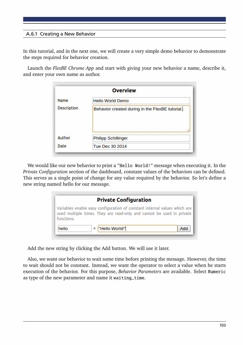
A.6.1 Creating a New Behavior
In this tutorial, and in the next one, we will create a very simple demo behavior to demonstratethe steps required for behavior creation.
Launch the FlexBE Chrome App and start with giving your new behavior a name, describe it,and enter your own name as author.
We would like our new behavior to print a "Hello World!"message when executing it. In thePrivate Configuration section of the dashboard, constant values of the behaviors can be defined.This serves as a single point of change for any value required by the behavior. So let’s define anew string named hello for our message.
Add the new string by clicking the Add button. We will use it later.
Also, we want our behavior to wait some time before printing the message. However, the timeto wait should not be constant. Instead, we want the operator to select a value when he startsexecution of the behavior. For this purpose, Behavior Parameters are available. Select Numericas type of the new parameter and name it waiting_time.
103
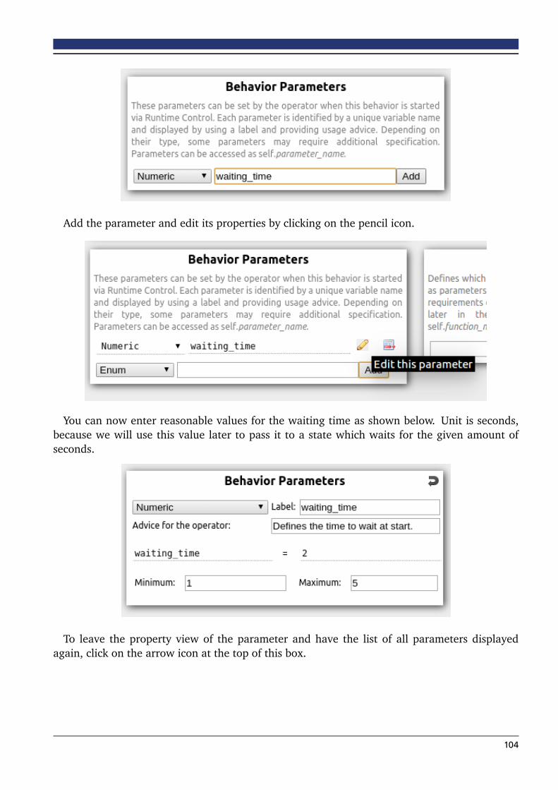
Add the parameter and edit its properties by clicking on the pencil icon.
You can now enter reasonable values for the waiting time as shown below. Unit is seconds,because we will use this value later to pass it to a state which waits for the given amount ofseconds.
To leave the property view of the parameter and have the list of all parameters displayedagain, click on the arrow icon at the top of this box.
104

We started creating our new behavior by defining some values (one constant, one variable)and can now proceed to define the state machine of the behavior. Your Behavior Dashboardshould now look like shown below. Click Statemachine Editor at the top to switch to the editorand continue with the next tutorial.
105

A.6.2 Using the Statemachine Editor
Start implementing the behavior by adding its first state. As written in the first tutorial, we wantour behavior to wait for some time and then print a message. So our first state will be a statewhich waits a given amount of seconds.
Click Add State at the top, enter a name for the new state and select WaitState from the listbelow. Entering something like "wait" in the class filter will help to quickly find the state andwould also help if we didn’t know the exact name and just need any state for waiting.
Now click Add to add the new state to the behavior state machine.
The properties of the newly added state will pop up. This panel can also be displayed byclicking on the state. Since we already defined a parameter for the waiting time, we can useit now. References to parameters always start with a self. in front of the parameter name.This helps to distinguish between parameters and constants. However, you can just start typingwaiting_time and let autocompletion do the rest.
106

Click Apply to make this change permanent.
Next, we add our second state the same way. This time, it’s a LogState as shown belowbecause now we want to print our message.
107

This state has two parameters which we can now edit in the properties panel.
The first one is the text to be printed. As we did for the waiting state, we won’t enter anexplicit value, but instead refer to one of our already defined values. So, just enter the name ofour message string, hello, as value of the text parameter. As soon as you click Apply, you willalso see its value as tooltip when hovering over the text field.
The second parameter defines the type of the message such as error or warning. The defaultvalue should be fine this time. Normally, behavior hints are used to give explicit instructions orreminders to the operator when he is expected to do something.
This time, we will also change the required level of autonomy of this state’s outcome. SelectHigh and apply the change. The meaning of this Autonomy Level is explained in the next tutorial.
Now connect the added states.
Start with setting the initial state by clicking on the black bullet next to the waiting state first,and then clicking on the waiting state to connect it to the bullet. You may also change theposition of the states by dragging them at their top right corner (indicated by a move icon).
108

The unconnected outcomes of each state are listed at the bottom of each state’s visualization.First, click on the outcome you want to connect and then click on the target. The two bulletsat the bottom of the state machine are the outcomes of the state machine itself. You can ignorethe outcome failed for now.
Your state machine should now look similar to the one shown below.
The green color of the second transition refers to its required autonomy level.
Now save the behavior. This will generate all files required for executing the new behavior.
Since you added a new ROS package by creating a new behavior, catkin needs to configurethis new package. In order to do so, close the Chrome App after saving and run catkin_make.This step is only required when adding a new behavior. Changes to a behavior do not requirethis process.
109

A.6.3 Execution of a Behavior
You should have completed the first two tutorials or at least have access to the created behavior.Now we want to execute a behavior. This means, it is no longer sufficient to just launch theFlexBE Chrome App. Instead, we need to launch the whole behavior engine. This can be doneby executing the following command:
roslaunch flexbe_onboard behavior_testing.launch
First, you have to load the previously created behavior. This is done by clicking on the LoadBehavior button at the top and then selecting your Hello World Demo in the list of availablebehaviors. Similar to choosing a class when adding a new state, you can again start typing partsof the name into the filter text field to quickly find what you are looking for.
Now, switch to the Runtime Control view of the user interface. It should look like shown below.
110

In order to run the behavior, now click the green Start Execution button. As soon as youclick the button, several things will happen. The user interface informs the onboard engine aswell as the behavior mirror. The mirror will create a behavior with the same structure as theonboard behavior in order to provide meaningful information by just receiving minimal datafrom onboard, while the onboard engine now imports the sent behavior, builds it, and startsexecution. When everything is running as it should, the main panel will display the first state ofour behavior as the currently active state.
111

The active state is always displayed in the center of the panel in blue color. On the right, youcan see possible outcomes of the state including the state which would be executed next.
After two seconds, the behavior continues with the next state.
As you can see now, the behavior does not continue after reaching the second state. Instead,it highlights the outcome and asks for permission to execute it. We will allow it in a moment,but first, take a look at the bottom panels. You can now see the Hello World message displayedin the feedback panel, as well as a documentation of the LogState in the documentation panel.
Allow the requested outcome by clicking on the highlighted arrow. You can click on outcomesat any time, even if they are not highlighted, in order to force them. The behavior will imme-diately return outcomes requested in this way, so it is your responsibility to decide whether anoutcome should be forced. After permitting the outcome, the demo behavior finishes.
Let’s do a second run of this behavior, but this time, we change the default settings. Increasethe waiting time to four seconds and change the Autonomy Level to Full by selecting the respec-tive entry at the control panel. Changing the Autonomy Level can be done at any time, no matterif a behavior is running or not.
112
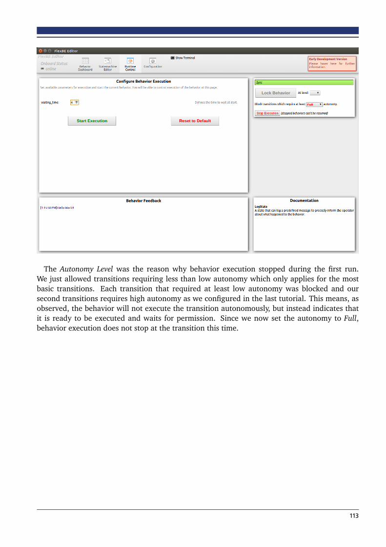
The Autonomy Level was the reason why behavior execution stopped during the first run.We just allowed transitions requiring less than low autonomy which only applies for the mostbasic transitions. Each transition that required at least low autonomy was blocked and oursecond transitions requires high autonomy as we configured in the last tutorial. This means, asobserved, the behavior will not execute the transition autonomously, but instead indicates thatit is ready to be executed and waits for permission. Since we now set the autonomy to Full,behavior execution does not stop at the transition this time.
113