an analysis and modeling of the dynamic stability of the
TRANSCRIPT

Mechanics and Mechanical Engineering
Vol. 22, No. 4 (2018) 1287–1299c© Technical University of Lodz
An Analysis and Modeling of the Dynamic Stability of the CuttingProcess Against Self-Excited Vibration
A. Motallebia
Department of Mechanical Engineering, Khoy BranchIslamic Azad University, Khoy, Iran
A. Doniavi
Department of mechanical EngineeringUrmia University,Urmia,Irane-mail: [email protected]
Y. Sahebi
Department of Mechanical Engineering, Khoy BranchIslamic Azad University, Khoy, Iran
Received (12 Ferbruary 2018)
Revised (14 June 2018)
Accepted (20 November 2018)
Chatter is a self-excited vibration which depends on several parameters such as thedynamic characteristics of the machine tool structure, the material of the work piece,the material removal rate, and the geometry of tools. Chatter has an undesirable effect ondimensional accuracy, smoothness of the work piece surface, and the lifetime of tools andthe machine tool. Thus, it is useful to understand this phenomenon in order to improvethe economic aspect of machining. In the present article, first the theoretical study andmathematical modeling of chatter in the cutting process were carried out, and then byperforming modal testing on a milling machine and drawing chatter stability diagrams,we determined the stability regions of the machine tool operation and recognized thatwitch parameter has a most important effect on chatter.
Keywords: machine tool vibrations, chatter, stability, modeling.
1. Introduction
Chatter is a self-excited vibration which occurs if the chip width is too large withrespect to the dynamic stiffness of the system. Variable forces generated during themachining operation leads to vibrational excitation of the tools and workpiece andas a result, the surface of the workpiece becomes wavy. In the next machining stage,if the generated wavy surface is not in phase with the wavy surface of the previousstage, the thickness of the chip becomes variable and it will lead to a change in

1288 An Analysis and Modeling of the Dynamic Stability of the Cutting Process . . .
the shear force. The change in the shear force will change the energy entering thesystem – including tools and workpiece.
And if the system does not have the capacity for the extra energy input, it willstart vibrating which is referred to as chatter. Chatter vibration has an exponentialgrowth in amplitude over time, and this continues until the tool is separated fromthe workpiece or that it breaks. This phenomenon can be distinguished by its soundor its marks on the workpiece surface.
Machining with chatter is in most cases an unwanted phenomenon, since it hasan adverse effect on the surface of the workpiece and besides, it may break thetools or other parts of the machine tool. Therefore, the cutting width and materialremoval rate must be below the limit at which chatter occurs. From this perspective,chatter is a factor decreasing material removal rate before it is limited by the powerand moment of the machine tool.
The simplest theory for calculating the cutting force which has been used instudying the stability of machining processes was founded by Tlusty [11]. Rao etal. [2] presented a cutting force model of oblique turning process and used it fordrawing chatter stability diagrams. Baker and Rouch [3] used a finite element modelfor analyzing the stability of the turning process. In references [4–7] the effect of toolwear parameter on chatter has been examined. Tang [5] controlled chatter in theturning process by placing piezoelectric actuators on the tool. Liao [6] controlledchatter using a system for automatic spindle speed regulation. Pan et al. [7–12]developed an intelligent system for controlling chatter in the turning process usingneural networks.
The width of the chip is the most important factor which plays a crucial rolein generating chatter vibration. If chip width is small enough, machining will bestable. With the increase of material removal width, chatter starts at a b limitand will be very severe for chip widths larger than this. The critical chip widthdepends on some factors such as the dynamic characteristics of the machine toolstructure, the material of the workpiece, material removal rate, and the geometryof tools [8]. A negative cutting angle will increase the possibility of chatter, sincethe direction of cutting force with the negative cutting angle of tools will be mostlyalong the direction of vibration. The effect of the relief angle of the tool on theoccurrence of chatter is displayed in the figure. Since the tool moves on a wavysurface, the relief angle (the angle in the above figure) is always changing and inlocation B where the relief angle is negative, much energy is lost from the systemdue to the contact between the tool and the workpiece. This phenomenon has beendiscussed as process damping [13] and is more noticeable at lower cutting speeds,since at higher cutting speeds the wavelength of oscillations increases and assumingthe constancy of the vibration amplitude, the slope of the oscillations decreases andthus there will be less change in the relief angle [8–15].

A. Motallebia, A. Doniavi and Y. Sahebi 1289
2. Results and Discussion
2.1. Modeling a Fixed-Hinged Beam with Cutting Tool in the Middle ofthe Beam
The work piece studied in this article is a fixed-hinged beam; thus considering thenew conditions, a support is obtained for the beam using the following equations:
∂u2∂x
=T
GJU3 + θ3
∂u3∂x
=−TGJ
U2 − θ2∂θ2∂x
=M2
EI22+
T
GJθ3
∂θ3∂x
=M3
EI33− T
GJθ2
∂M2
∂X= J22
∂2θ2
∂t2−[
T
EI33− T
GJ
]M3 + V3 (1)
∂M3
∂X= J33
∂2θ3
∂t2−[
T
EI22− T
GJ
]M2 − V2
∂V 2
∂X= n0
∂2U2
∂t2− PM3
EI33+
T
GJV3 − F1
∂V 3
∂X= n0
∂2U3
∂t2+PM2
EI22− T
GJV2 − F2
where θ2 and θ3 are the rotations of the beam in the 2 and 3 directions, U2 andU3 are displacements of the beam in the 2 and 3 directions, M2 and M3 are thebending moments in these two directions, V2 and V3 are the shear forces in thesetwo directions novel method based on CEEM method to model five-axis cuttingforce.
3. Solving the Equations Governing the Beam
The studied beam is a steel beam with 1m length and 1cm×2cm rectangular cross-section. We take the vector of unknowns as[
U2 U3 θ2 θ3 M2 M3 V2 V3]
and use the method of separation of variables in order to solve the equations. Thatis:
z (x, t) = z(x)eiωτ (2)
The dynamic equations of the system consisting of 8 equations varying with time andspace are solved using the method of separation of variables with respect to timeand space. The dynamic effect of the temporal term appears in these equationsin the form of a frequency term. By eliminating the temporal dependence fromdynamic equations governing the behavior of the system, we arrive at 8 spatialequations for positions along the beam which can be solved by applying boundaryconstraints (conditions) with respect to space which are given in Fig. 4.2(a).
1290 An Analysis and Modeling of the Dynamic Stability of the Cutting Process . . .
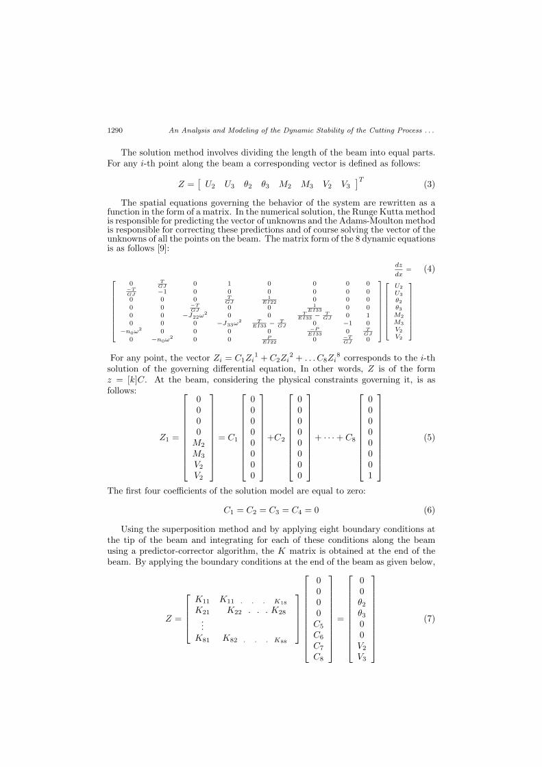
The solution method involves dividing the length of the beam into equal parts.For any i-th point along the beam a corresponding vector is defined as follows:
Z =[U2 U3 θ2 θ3 M2 M3 V2 V3
]T(3)
The spatial equations governing the behavior of the system are rewritten as afunction in the form of a matrix. In the numerical solution, the Runge Kutta methodis responsible for predicting the vector of unknowns and the Adams-Moulton methodis responsible for correcting these predictions and of course solving the vector of theunknowns of all the points on the beam. The matrix form of the 8 dynamic equationsis as follows [9]:
dz
dx= (4)
0 TGJ 0 1 0 0 0 0
−TGJ −1 0 0 0 0 0 00 0 0 T
GJ1
EI22 0 0 0
0 0 −TGJ 0 0 1
EI33 0 00 0 −J22ω
2 0 0 TEI33 −
TGJ 0 1
0 0 0 −J33ω2 T
EI33 −TGJ 0 −1 0
−n0ω2 0 0 0 0 −P
EI33 0 TGJ
0 −n0ω2 0 0 P
EI22 0 −TGJ 0
U2
U3
θ2θ3M2
M3
V2
V2
For any point, the vector Zi = C1Zi1 + C2Zi
2 + . . . C8Zi8 corresponds to the i-th
solution of the governing differential equation, In other words, Z is of the formz = [k]C. At the beam, considering the physical constraints governing it, is asfollows:
Z1 =
0000M2
M3
V2V2
= C1
00000000
+C2
00000000
+ · · ·+ C8
00000001
(5)
The first four coefficients of the solution model are equal to zero:
C1 = C2 = C3 = C4 = 0 (6)
Using the superposition method and by applying eight boundary conditions atthe tip of the beam and integrating for each of these conditions along the beamusing a predictor-corrector algorithm, the K matrix is obtained at the end of thebeam. By applying the boundary conditions at the end of the beam as given below,
Z =
K11 K11 . . . K18
K21 K22 . . . K28
...K81 K82 . . . K88
0000C5
C6
C7
C8
=
00θ2θ300V2V3
(7)

A. Motallebia, A. Doniavi and Y. Sahebi 1291
we arrive at the following equations:
k15C5 + k16C6 + k17C7 + k18C8 = 0
k25C5 + k26C6 + k27C7 + k28C8 = 0 (8)
k35C5 + k36C6 + k37C7 + k38C8 = 0
k65C5 + k66C6 + k67C7 + k68C8 = 0
The condition for the above homogeneous system (of the form K[C] = 0) to havea solution is that the determinant of matrix [K] equals zero. The result of thiscondition implies that det[K] = 0 is a function of ω. The natural frequencies ofthe model are obtained by numerically solving these equations. The figure belowdisplays the diagram of changes that has been estimated at the points where thisfunction meets the horizontal axis, and of course these frequencies are the naturalfrequencies of the system.
Figure 1 det(w) vs. w
The following diagram shows the variation of the first frequency of the beam withthe load applied at the end of the beam. According to the figure, the point wherefrequency reaches zero corresponds to the critical force for the buckling phenomenon.In the proposed model, the load applied at the end of the beam is the same as theload generated by the mandrel.
Figure 2 The natural frequency of the system in p (power) for finding
After numerical solution of the system, four natural frequencies are obtained andultimately the mode shapes related to each of these frequencies are drawn which,correspond to beam displacement and beam and bending.

1292 An Analysis and Modeling of the Dynamic Stability of the Cutting Process . . .
Figure 3 Mode shapes and (displacements in the 2 and 3 directions)
Figure 4 Mode shapes related to rotations θ2 and θ3
Figure 5 Mode shapes related to bending moments M2 and M3
Figure 6 Mode shapes related to shear forces V2 and V3

A. Motallebia, A. Doniavi and Y. Sahebi 1293
3.1. The Dynamic Equations Governing the Behavior of the CylindricalWork piece
In the next stage of system simulation, a cylindrical work piece with length andradius has been used instead of a work piece with a rectangular cross-section, andin this situation the equations governing the dynamic behavior of the system aresimplified as follows:
∂U
∂X− θ = 0
∂θ
∂X− M
EI= 0
J∂2θ
∂t2− ∂M
∂X+ V = 0 (9)
n0∂2θ
∂t2− P
EI.M − ∂V
∂X= F
By arranging the equations governing the cylindrical beam under the load wehave:
Z =
n0 0 0 00 −J 0 00 0 0 00 0 0 0
ϑ2Uϑ2
ϑ2θϑ2
ϑ2Mϑ2
ϑ2Vϑ2
+
0 0 0 +10 0 +1 00 +1 0 0
+1 0 0 0
ϑUϑXϑθϑXϑMϑXϑVϑX
+
0 0 + P
EI 00 0 0 −10 0 −1
EI 00 −1 0 0
UθMV
=
F000
(10)
Or in the general form of
A1∂2Z
∂t2− ∂Z
∂X+A2Z = b. (11)
z(t, x) =
∫ n
j=1
fj(t)Z(j)0 (x) (12)
Considering the generalized principle of virtual work, we have∫ 1
0
[L(z)E0Z0
(i)]dx = 0 (13)
And in the above relation
L (Z) = A1∂2Z
∂t2+A2
∂Z
∂t− ∂Z
∂XA3Z = b (14)
Finally, by simplifying and integrating the above relations we come to the followingrelation: ∫ k
j=1
aijd2fjdτ2
+ bijdfjdτ
+ cijfj = dijϕj , i, j = 1 . . . k (15)

1294 An Analysis and Modeling of the Dynamic Stability of the Cutting Process . . .
Where the number of vibrational modes is used which are obtained by solving thefree vibration of the system corresponding to each of the displacements, rotations,moments, and shear forces. The vector form of the equation is as:
Ad2f
dτ2+B
df
dt+ Cf = D∆T (16)
So that in the above relations we have:
A = [aij ] , B = [bij ] , C = [cij ] , D = [dij ] (17)
aij =∫ 1
0{A1Z0
(j)E0Z0(i)}dx
cij =∫ 1
0A3Z0
(j) − dZ0(j)
dX E0Z0(i) dx
(18)
By providing a computer code for solving the system using the algorithm presentedabove, and are obtained which correspond to the mass and fitness of the system.Considering the way of aligning the tool relative to the workpiece, we expect thefirst mode shape of the beam to be excited and the effect of the following modeshapes to be insignificant in comparison with the effect of the first frequency. Thus,by eliminating the effect of higher frequencies, we can assume the model of theworkpiece as a system with one degree of freedom. Considering the fact that thevalue of for the first frequency is equivalent to the mass of the system with onedegree of freedom and the value of is equivalent to the stiffness of the system withone degree of freedom, we can assume that the system has a damping coefficient. Inthis model, the damping coefficient for the cutting dynamics has been empiricallyobtained; thus, our workpiece model is a simple mass-spring-damper model. It mustbe noted that since the piece is cut at the middle, the first frequency is excited andthe subsequent effects are eliminated.
4. Mechanisms of Chatter Phenomenon in Machining
Self-excited vibrations in machine tools are due to two fundamental mechanisms,mode coupling and regeneration of waviness, and in this section we will explainthese mechanisms.
4.1. Mode Coupling Effect
Self-excited vibrations due to mode coupling occur when there are vibrations be-tween the tool and the workpiece at the same time and in two different directions.As can be seen in the figure, the tool and its support are modeled as a concentratedmass, m1, and two springs, Ak1 and k21, orthogonal to one another. If we as-sume that the movement of the workpiece is from right to left and the tool is fixed,clearly the shear force will lead to vibrational motion in two orthogonal directionswith different amplitudes, and as a result the tool tip will move in an elliptical path.Now, taking into consideration the shape and direction of the tool tip inside theworkpiece, for a part of the path where the tool tip travels the distance from A to B(considering the direction of the shear force), the direction of the force is oppositeto the displacement and it will lead to energy loss. In the second part of the pathfor the cycle to become complete, the tool tip travels the distance from B to A. Inthis part of the path, the direction of the shear force and the displacement of the

A. Motallebia, A. Doniavi and Y. Sahebi 1295
tool tip are the same which will cause energy to transfer from the workpiece to thetool. Since the cutting depth in the B to A path is larger than the A to B pathand considering the approximate equality of the two paths, the energy transferredto the tool is greater than the energy lost from it. This surplus of energy of thetool will sustain its vibrations against damping losses and as a result the tool willcontinue its vibrations [11,14].
4.2. Waviness Regeneration
In machining operations, machining is done on a surface that has already beenproduced by the tool in the previous pass. This surface has been produced bythe previous tooth in the milling operation and by the previous revolution in theturning operation. If for any reason (e.g., bending vibrations of the workpiecedue to the cutting force) a relative oscillation is produced between the tool andthe workpiece, the tool tip will encounter a wavy surface in the next pass (the nextrevolution in the turning operation and the next tooth in the milling operation) andconsequently it will lead to an alternating change in chip thickness and the resultwill be the alternating change of the machining force. This alternating cutting forcewill intensify vibrations and their amplitude will vary depending on the machiningconditions. Thus, the newly generated surfaces will also be wavy. Accordingly,the generation of wavy surfaces will ceaselessly continue and the phase differencebetween wavy surfaces in two consecutive passes will be constrained by the geometryof the machining operation; this phase difference in turn affects the regeneration ofwavy surfaces (Fig. 4).
In the turning operation, the phase difference between two consecutive wavescan be denoted by the relationship between the revolution speed of the spindle nand vibration frequency N+ ε
2π −fn‘ where N is the maximum number of full waves
on the workpiece so that ε2π < 1. In other words, full waves and a part of a full wave
( ε2π ) are produced on the workpiece surface. As can be seen in th figure, depending
on the value of, chip thickness variation (Y0−Y ) can be either equal to zero (if ε iszero) or a maximum value. Clearly, if ε is zero, there will be no chatter, since thewavy surfaces in two consecutive passes will be parallel and consequently there willbe no change in the cutting force which is due to chip thickness variation.
4.3. Analysis of the Chatter in Turning Process
Assume that in turning process, the tool is machining in the direction orthogonal tothe workpiece axis. The bending vibrations of the workpiece due to the cutting forcewill generate a wavy surface on its cross-section. If the workpiece is modeled usinga model with one degree of freedom as specified in Fig. 5, the vibration equation ofthe system will be of the form of relation (1):
my y (t) + cy y (t) + kyy (t) = F (t) (19)
The machining force F (t) can be calculated from the following relation:
F (t) = kfah(t) (20)
1296 An Analysis and Modeling of the Dynamic Stability of the Cutting Process . . .
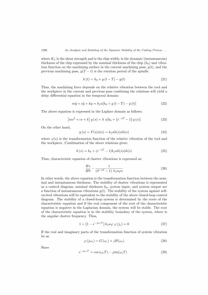
where Kf is the shear strength and is the chip width; is the dynamic (instantaneous)thickness of the chip expressed by the nominal thickness of the chip (h0) and vibra-tion function on the machining surface in the current machining pass, y(t), and theprevious machining pass, y(T − t) is the rotation period of the spindle.
h (t) = h0 + y (t− T )− y(t) (21)
Thus, the machining force depends on the relative vibration between the tool andthe workpiece in the current and previous pass combining the relations will yield adelay differential equation in the temporal domain:
my + cy + ky = kfa[h0 + y (t− T )− y (t)] (22)
The above equation is expressed in the Laplace domain as follows:[ms2 + cs+ k
]y (s) = k a[h0 +
(e−sT − 1
)y (s)] (23)
On the other hand,
y (s) = F (s)φ(s) = kfah(s)φh(s) (24)
where ϕ(s) is the transformation function of the relative vibration of the tool andthe workpiece. Combination of the above relations gives:
h (s) = h0 + (e−sT − 1)kfah(s)φh(s) (25)
Thus, characteristic equation of chatter vibrations is expressed as:
Hs
H0− 1
(ϑ−sT − 1) hfaϕs(26)
In other words, the above equation is the transformation function between the nom-inal and instantaneous thickness. The stability of chatter vibrations is representedas a control diagram; nominal thickness h0, system input, and system output area function of instantaneous vibrations y(t). The stability of the system against self-excited vibrations will be equivalent to the stability of the above closed-loop controldiagram. The stability of a closed-loop system is determined by the roots of thecharacteristic equation and if the real component of the root of the characteristicequation is negative in the Laplacian domain, the system will be stable. The rootof the characteristic equation is in the stability boundary of the system, where isthe angular chatter frequency. Thus,
1 +(1− e−jωcT
)kfaϕ ϕ (jc) = 0 (27)
If the real and imaginary parts of the transformation function of system vibrationbe as
ϕ (jωc) = G (ωc) + jH(ωc) (28)
Since
e−jωcT = cos (ωcT )− jsin(ωcT ) (29)

A. Motallebia, A. Doniavi and Y. Sahebi 1297
The combination of the above relations gives:
{1 + kja[G(ωc)(1− cos(ωcT ))−H(ωc) sin(ωcT )]}+
j{kfa[G(ωc) sin(ωcT ) +H(ωc)(1− cos(ωcT ))]} = 0 (30)
which will be obtained from the latter relation of the system of equations.
G(ωc) sin(ωcT ) +H(ωc)(1− cos(ωcT )) = 0 (31)
and
1 + kfa[G(ωc)(1− cos(ωcT ))]−H(ωc)sin (ωcT ) = 0 (32)
In the above relations, chip width ( a ) is a parameter that depends on the machiningprocess. Thus, the goal is to determine the chip width values that put the systemat the stability boundary.
If is the phase angle of the transformation function of the system at the stabilityboundary, then,
tan Ψ = H(ωc)/G(ωc) (33)
And finally we come to the following relation:
alim =−1
2kfG(ωc)(34)
The above relation indicates the maximum cutting width which can exist withoutchatter vibrations. Since cutting width is a quantity whose negative value hasno physical meaning, the above equation only holds for the negative values of thereal part of the transformation function. This equation expresses that the criticalcutting width has an inverse relationship with the flexibility if the machine tool; themore flexible the structure and the greater the cutting strength are, the lower willbe the critical cutting width value and chatter vibrations will start at lower valuesof cutting width.
5. Analysis and Dynamic Modeling of Cutting
In the present paper, the dynamic model of the studied machining system is asbelow, where the dynamics governing cutting are described by the Mathieu equationand this behavior of the equation has been modeled using the Simulink extensionof the Matlab Software.
Figure 7 The dynamic model of the machining system

1298 An Analysis and Modeling of the Dynamic Stability of the Cutting Process . . .
I =
∫ t
0
πd
60(n0t+ ∆n sinωN t) dt =
πD
60(n0 + ∆nsin(ωN t))
2(35)
c(1) =πDm∆nωn
60cos(ωN t
)+πDc
60
(n0 + ∆n sin(ωN t)
)(36)
k(1) = k , b1(1) = −c3(t)(b0 + c1) cos θ (37)
c1 = a0 cot(kγ + k′γ) + tan θ c3 =2τS sin(β − γ)
cot(β − γ)− sin(β − γ)(38)
Finally, we obtain:
my′′(t) + cy′(t) + ky(t) = −c3(t) cos θ ((b0 + c1)y(t)) (39)
Figure 8 Amplitude versus time for n0 = 850, y = −8 and b = 0.2 (towards stability)
In order to examine the effects of the parameters y′ and h0, on the chatterphenomenon, different pairs of effective parameters have been simulated and someof them are presented in Figs. 8 and 9.
Figure 9 Amplitude versus time for n0 = 325, y = −8 and b = 0.2 (stability state)

A. Motallebia, A. Doniavi and Y. Sahebi 1299
6. Conclusion
In obtaining the natural frequencies of a system, if the load (the force exerted onthe cylindrical workpiece due to closing the mandrel) is exerted on the workpiece,the natural frequency of the system (ω) will decrease due to the reduction of beamstiffness. If we draw the diagram of (mandrel force) in (natural frequency), thecritical point for the force will be: Pcr = 6730 N.
References
[1] Tlusty, G. and Polacek, M.: The stability of machine tools against self-excitedvibrations in machining, in: Proceedings of the ASME International Research in Pro-duction Engineering, Pittsburgh, USA, 465–474, 1963.
[2] Rao, B. and Shin, Y.C.: A Comprehensive Dynamic Cutting Force Model for Chat-ter Prediction in Turning, International Journal of Machine Tools and Manufacture,39, 1631–1654, 1999.
[3] Baker, J.R. and Rouch, K.E.: Use of Finite Element Structural Models in An-alyzing Machine Tool Chatter, Finite Elements in Analysis and Design, 38(11),1029–1046, 2002.
[4] Chiou, Y.S. and Liang, S.Y.: Chatter Stability of a Slender Cutting Tool in Turn-ing with Tool Wear Effect, International Journal of Machine Tools and Manufacture,38(4), 315–327, 1998.
[5] Tang, Y.S., Kao, J.Y. and Lee, E.C.: Chatter suppression in turning operationswith a tuned vibration absorber, Journal of Materials Processing Technology, 105,2000.
[6] Chen, M.:. Self-induced chatter vibration of lathe tools, 1972.
[7] Galewski, M. and Kalinski, K.: Vibration surveillance during high speed millingwith variable spindle speed, The Publication of Gdansk University of Technology (inPolish), Gdansk, 2009.
[8] Schmitz, T.L., Burns, T.J., Ziegerta, J.C., Duttererc, B. and Win-fough, W.R.: Tool Length-Dependent Stability Surfaces, Machining Science andTechnology, 8(3), 377–397, 2004.
[9] Yosuke, M., Takashi, M. and Eiji, U.: Simulation Analysis of Self-Excited ChatterVibration with Taking the Non-Linearity of Machine-Tool Structure into Account, 3rdReport, Journal of the Japan Society for Precision Engineering, 2008.
[10] Altintas, Y.: Manufacturing Automation. Metal Cutting Mechanics, Machine Tool,Vibrations and CNC Design, Cambridge University Press, 2009.
[11] Tlusty, G.: Manufacturing processes and Equipment, 2000.
[12] Ulf J., Aarsnes, F., Morten Aamo, O.: Linear stability analysis of self-excitedvibrations in drilling using an infinite dimensional model, Journal of Sound and Vi-bration, 360, 239–259, 2016.
[13] Anindya, M., Chatterjee, S.: Modal self-excitation by nonlinear acceleration feed-back in a class of mechanical systems, Journal of Sound and Vibration, 376, 1–17,2016.
[14] Sunb, C., Altintasa, Y.: Chatter free tool orientations in 5-axis ball-end milling,International Journal of Machine Tools and Manufacture, 106, 89–97, 2016.
[15] Erdbrink, D.E., Krzhizhanovskaya, V.V.: Differential evolution for system iden-tification of self-excited vibrations, Journal of Computational Science, 10, 360–369,2016.
