an all-electric take-off and climb assisting aircraft
TRANSCRIPT

An All-Electric Take-Off and Climb Assisting Aircraft
Conceptual Design and Quantification of the Emissions Reduction Potential
Master of Science Thesis
Arnault-Quentin Eggermont
Royal Netherlands Aerospace Centre
Delft University of Technology – Faculty of Aerospace Engineering
The Netherlands
2021

This page was intentionally left blank.

An All-Electric Take-Off and Climb Assisting Aircraft
Conceptual Design and Quantification of the Emissions Reduction Potential
By
A.A.L.A.X.A.V. Eggermont
4112199
in partial fulfilment of the requirements for the degree of
Master of Science
in Aerospace Engineering
at the Delft University of Technology
to be defended publicly on May 26 2021 at 09:30.
Supervisor: Ir. J.A. Melkert, TU Delft
Thesis Committee: Dr. Ir. G. La Rocca, TU Delft
Prof. Dr. P. Vink, TU Delft
Dr. Ir. W.J. Vankan, NLR
An electronic version of this document is available at http://repository.tudelft.nl

This page was intentionally left blank.

i
Preface
Dit verslag vormt het sluitstuk van mijn afstudeerstage bij het Koninklijk Nederlands Lucht- en Ruimtevaartcentrum (NLR). Niettegenstaande de individuele aard van de opdracht, heb ik kunnen rekenen op de ondersteuning van diverse personen. Hen ken ik bij deze graag een eervolle vermelding toe.
Allereerst bedank ik mijn dagelijkse begeleider Jos Vankan voor het vertrouwen, de toewijding en het nodige geduld. Verder ben ik ook NLR-collega’s Wim Lammen, Jonathan Derei, Edward Rademaker en Oscar Kogenhop dankbaar voor hun inhoudelijke inbreng. Assia Haddou en Huy Tran bezorgden me niet alleen een warme ontvangst en vermakelijke momenten op kantoor, maar bleken ook een waardevol klankbord op momenten dat ik dat kon gebruiken. Ik betuig ook uitdrukkelijk mijn dank voor het mentorschap van Rob Brink.
Uiteraard zet ik eveneens graag enkele individuen bij de TU Delft in de bloemetjes. Ik druk mijn oprechte dank uit voor de begeleiding door Joris Melkert en professor Peter Vink. Verder bedank ik dr. Roelof Vos voor het faciliteren van mijn literatuurstudie en dr. Arvind Rao voor zijn kritische blik voor aanvang van mijn stage.
Daarnaast spreek ik tevens welgemeende woorden van dank uit voor mijn rots in de branding Renske Oldenboom en de grafische ondersteuning van Robert Ellents. Ook Simon Andrew en Rein Sevenstern mogen uiteraard niet ontbreken; de zachte landing in Amsterdam was uiterst betekenisvol.
Met de oplevering van dit document komt er ook een einde aan mijn studententijd in Delft. Filmhuis Lumen en huurdersorganisatie WijWonen zijn daar onlosmakelijk mee verbonden. Ik noem tevens expliciet Maneesh, Jules, Ren, Robbert, Frederick, Philip, Mitchell, Robin, David, Igor, Jasmijn, Maud, Naghme, Daniela, Pierre, Jacqueline, Stefanie, Corrinda, Carien en IHE Delft. Ik ben ontzettend dankbaar voor de mooie herinneringen, die voor altijd mijn hart een stukje blauw doen kleuren.
Tenslotte geef ik mijn familie erkenning voor de financiële ondersteuning alsook mijn vrienden voor het warme hart dat ze mij toedragen.

ii
Summary
The aviation industry has set ambitious emission reduction targets for 2050. Following the success of electrification in the automotive industry, the potential of hybrid electric propulsion (HEP) has been the subject of many scientific projects. The energy and power of the electric systems that support the aircraft propulsion system are typically applied during the energy-intensive take-off and climb phases of the flight. This results in a considerable mass penalty for the remainder of the mission.
An all-electric unmanned aerial vehicle, which decouples from the main aircraft at the cruise altitude and returns the electric propulsive system to the departure airport, could thus allow to limit the environmental footprint of a particular flight.
The present study has quantified the potential fuel, energy and emission reductions of an Airbus A320neo assisted by such an auxiliary aircraft. This potential is also compared to a parallel-hybrid A320neo entering into service in 2035.
The required modelling and mission evaluations have been performed with the MATLAB-based integrated simulation framework ‘Mission, Aircraft and System Simulation’ (MASS). The mission, aircraft and engine models of this tool, developed at the Royal Netherlands Aerospace Centre (NLR) throughout multiple HEP studies, have been modified. Besides, constraints for engine temperatures and shaft speeds have been applied.
For the 3,500 nautical miles (6,482 kilometres) design mission, fuel and energy reductions of about four and two and a half per cent are found respectively. For the 850 nautical miles (1,574.2 kilometres) standard mission, a fuel reduction of about five per cent can be achieved. The overall energy demand increases slightly in comparison with the reference Airbus A320neo. No feasible parallel hybrid-electric design point was identified for these two mission profiles.
In order to account for the uncertainty inherent to a preliminary design stage, the impact of multiple model parameter variations is assessed in a design study. In the vast majority of the investigated scenarios, single digit fuel and emissions savings can still be realised with this innovative aircraft architecture.
A more detailed aerodynamic analysis and further refinement of the propulsive system model are recommended subjects for subsequent research.

iii
Table of Contents
List of Figures iv
List of Tables v
Nomenclature vi
1. Introduction 1
2. Background 3
2.1 On-Board Systems 3
2.1.1 Jets & Rockets 3
2.1.2 Landing Gear Motors 3
2.2 External Systems 3
2.2.1 Taxi Assistance 4
2.2.2 Take-Off Assistance 5
2.2.3 Taxi, Take-Off and (partial) Climb Assistance 6
3. Methodology 8
3.1 Functional Analysis 8
3.2 Simulation Framework 8
3.3 Modifications 10
3.3.1 Mission Model 10
3.3.2 Aircraft Model 11
3.3.3 Engine Model 12
3.4 Constraints 13
4. Results & Discussion 14
4.1 Verification 14
4.2 Reduction Potential 15
4.2.1 Take-Off and Climb Assisted Aircraft System 15
4.2.2 Parallel Hybrid-Electric Aircraft 18
4.3 Design Study 19
4.4 Conceptual Design & Qualitative Analysis 20
5. Conclusion & Recommendations 22
Bibliography 23
A. Appendix A 27
B. Appendix B 28
B.1 Standard Mission 28
B.2 One Engine Inoperative Scenario 29
B.3 Balked Landing Scenario 30
iv
List of Figures
Figure 1 Illustration of the Take-Off Drone Concept 2 Figure 2 WheelTug 4 Figure 3 TaxiBot at Schiphol Airport 4 Figure 4 Airbus Concept Plane Taking Off with GroLaS 6 Figure 5 GABRIEL 6 Figure 6 Electric Engine Accelerator 7 Figure 7 Airbus’s Patented Auxiliary Air Vehicle 7 Figure 8 Flowchart of Mission Aircraft and Systems Simulation for HEP
performance analysis (MASS) 9 Figure 9 Mission Profiles: (a) Standard Mission, (b) Design Mission,
(c) One Engine Inoperative Scenario, (d) Balked Landing Scenario 10
Figure 10 Variation of the Thrust Specific Fuel Consumption at 35,177 ft (10,722 m) with varying Relative Engine Core Size (a) and Bypass Ratio (b) 12
Figure 11 Variation of the System Mass during the Design Mission with(out) the Auxiliary Aircraft 14
Figure 12 Variation of the Thrust during the Design Mission without (a) and with (b) the Auxiliary Aircraft 15
Figure 13 Variation of the Low Pressure Spool Speed (a), High Pressure Spool Speed (b), Turbine Inlet Temperature (c) and Exhaust Gas Temperature (d) during the Design Mission with(out) the Auxiliary Aircraft 16
Figure 14 Variation of the Thrust Split during the Assisted Design Mission 16
Figure 15 Variation of the Low Pressure Spool Speed during the Design Mission for the Reference and a Hybrid-Electric Aircraft (RECS = 0.99) 18
Figure 16 Artist Impression of the Take-Off and Climb Assisted Aircraft System 20
Figure 17 Matching Chart of the Airbus A320 27 Figure 18 Variation of the Low Pressure Spool Speed (a), High Pressure
Spool Speed (b), Turbine Inlet Temperature (c) and Exhaust Gas Temperature (d) during the Standard Mission with(out) the Auxiliary Aircraft 28
Figure 19 Variation of the Low Pressure Spool Speed (a), High Pressure Spool Speed (b), Turbine Inlet Temperature (c) and Exhaust Gas Temperature (d) during the OEI Scenario with(out) the Auxiliary Aircraft 29
Figure 20 Variation of the Low Pressure Spool Speed (a), High Pressure Spool Speed (b), Turbine Inlet Temperature (c) and Exhaust Gas Temperature (d) during the Balked Landing Scenario with the Original and Downscaled Engine 30

v
List of Tables
Table 1 Fuel, Emissions and Energy Variations for the Assisted Design Mission with respect to the Reference Aircraft 17
Table 2 Fuel, Emissions and Energy Variations for the Assisted Standard Mission with respect to the Reference Aircraft 17
Table 3 Results of the Design Study 19 Table 4 SWOT Analysis of the Take-Off and Climb Assisting Aircraft 21

vi
Nomenclature
AA Auxiliary Aircraft
CATO Catapult-Assisted Take-Off
CO Carbon Monoxide
CO2 Carbon Dioxide
EGT Exhaust Gas Temperature
EMALS Electromagnetic Aircraft Launch System
HE Hybrid-Electric
HEP Hybrid-Electric Propulsion
ICAO International Civil Aviation Organisation
JATO Jet-Assisted Take-Off
KLM Royal Dutch Airlines
MASS Mission, Aircraft and System Simulation for HEP performance analysis
MEA More Electric Aircraft
N1 Low Pressure Spool Rotational Speed
N2 High Pressure Spool Rotational Speed
NLR Royal Netherlands Aerospace Centre
NOx Nitrous Oxides
RATO Rocket-Assisted Take-Off
RECS Relative Engine Core Size
SWOT Strengths, Weaknesses, Opportunities, Threats
TIT Turbine Inlet Temperature
TOD Take-Off Drone
TRL Technology Readiness Level
TS Thrust Split
TSFC Thrust-Specific Fuel Consumption
UHC Unburned Hydrocarbons

vii
« Qu’est-ce que c’est que cette chose-là?
Ce n’est pas une chose. Ça vole. C’est un avion. C’est mon avion. »
Le Petit Prince, Antoine de Saint-Exupéry

viii
Dedicated to all for whom (higher) education is out of reach.

1
1. Introduction
Greenhouse gas emissions from commercial aviation continue to increase under normal circumstances on a yearly basis due to the growing international air traffic. The United Nations International Civil Aviation Organisation (ICAO) projects an increase in fuel consumption of 120 up to 210% by 2045 compared to 2015 (1). Over the same period, a compound annual growth rate of 4.1% for passenger transport and 3.6% for cargo traffic is anticipated (2).
Nevertheless, ambitious emission reduction targets have been adopted. The European Commission set out a 75% reduction in carbon dioxide emissions, 90% decrease of nitrous oxides and 65% less perceived noise by 2050 compared to the reference year 2000 for a (sub)system model or prototype demonstration in a relevant environment (TRL 6). Moreover, the taxiing phase should not generate any emissions at all (3). More recently, the European Green Deal tightened up the objective to a 90% cut in transport greenhouse gas emissions to achieve climate neutrality by the mid of the century (4).
Due to the success of hybridisation in the automotive industry, the electrification of commercial medium/long-range aircraft and their propulsive system has received increasing (research) interest (5–7). The Royal Netherlands Aerospace Centre (NLR) has also contributed with multiple studies that evaluated the trip energy and emissions of a parallel hybrid-electric A320neo for various hybridisation scenarios during the take-off, climb and cruise phases (8–14). The results of these studies have confirmed that there is a potential for trip fuel reduction as a result of the smaller core of the turbofan engine and the assistance of an electric motor.
During a workshop for the centennial anniversary of NLR, Royal Dutch Airlines (KLM) and GKN Fokker in March 2019, a group of students proposed an all-electric auxiliary aircraft. It assists the main aircraft during taxiing and the energy intensive take-off and climb phases, after which it decouples and returns autonomously to the airport. This take-off drone (TOD) concept is illustrated in Figure 1.
Such a configuration has the potential to enable emission-free taxiing and to generate propulsive power during the most power demanding legs in a fully electric fashion. This is expected to benefit the overall aircraft environmental performance in comparison to an architecture where the HEP system is present during the entire mission duration. The assessment of the net reduction potential of this system as well as the identification of its potential bottlenecks and showstoppers has remained unexplored.
This research project aims to quantify the fuel, energy and emissions (carbon monoxide (CO), carbon dioxide (CO2), nitrous oxides (NOx) and unburned hydrocarbons (UHC)) reductions of an A320 category aircraft assisted by a conceptually designed all-electric unmanned vehicle in comparison to a conventional and parallel-hybrid version of the same aircraft entering into service in 2035.

2
This objective can also be formulated as a question:
What is the fuel, energy and emissions (CO, CO2, NOx and UHC) reduction potential of equipping an A320 category aircraft with an all-electric unmanned auxiliary aircraft in comparison to a conventional and parallel-hybrid version of the A320neo on a reference mission?
Figure 1: Illustration of the Take-Off Drone Concept
This report is structured as follows. Chapter 2 presents an overview of assisted take-off concepts identified in scientific literature. The methodological approach is set forth in Chapter 3. In Chapter 4, the outcomes are presented and discussed. Chapter 5 concludes this report and contains recommendations for subsequent research efforts.

3
2. Background
Several varieties of take-off assistance have been identified in scientific literature. The findings of the literature review are summarized in this chapter. Two categories can be distinguished: on-board and external systems.
2.1 On-Board Systems
This section focuses on systems that remain present during the entire mission duration.
2.1.1 Jets & Rockets
Rocket- and Jet-Assisted Take-Off, often denoted as RATO and JATO respectively, have proven their potential to reduce the required runway length (15). The increased noise footprint and fuel burn as well as the higher accelerations it generates halted the introduction of these systems in commercial aviation.
2.1.2 Landing Gear Motors
As part of the recent industry interest for the More Electric Aircraft (MEA), the ‘Electric Wheel Drive Concept’ has been put forward as alternative taxiing method (16). Commercial aircraft rely on engine power for taxiing at operating points far below their design optimum. Rather than inefficiently using the aircraft engines for the journey towards the runway, an electric motor placed inside the nose and/or landing gear provides the required traction to set the aeroplane into motion. The lower power demand reduces the fuel burn and noise footprint of the engines. In addition, the possibility of ingesting debris surrounding the taxiway is lowered. Landing imposes high structural demands on this novel subsystem and its components however (17).
Safran and Honeywell Aerospace teamed up to create the eTaxi / Electric Green Taxi System (EGTS) and presented a full-scale demonstration on an Airbus A320 at the 2013 edition of the Paris Air Show (18). Unfortunately, the joint venture came to an end in 2016 (19).
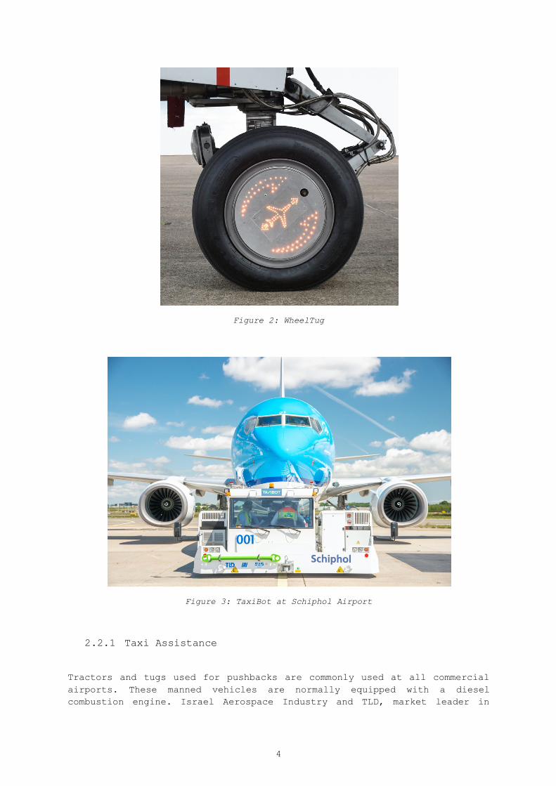
Another example of such a landing gear motor is WheelTug (20). Customers of the powered replacement nosewheel, illustrated in Figure 2, include KLM and Malaysian (21). Currently being certified by the FAA, it is expected to enter into service by the end of 2021 (22).
2.2 External Systems
This section presents an overview of the take-off assistance systems that are not on board during the entire mission duration.
4
Figure 2: WheelTug
Figure 3: TaxiBot at Schiphol Airport
2.2.1 Taxi Assistance
Tractors and tugs used for pushbacks are commonly used at all commercial airports. These manned vehicles are normally equipped with a diesel combustion engine. Israel Aerospace Industry and TLD, market leader in

5
aircraft ground equipment, are proposing TaxiBot. This semi-robotic hybrid dispatched towing system, shown in Figure 3, allows the pilot to be in command of the entire taxi phase without requiring any engine power (23). Reductions in fuel, air and noise pollution and increased airport efficiency have been demonstrated during operation at major international aerodromes (24). Between March and June 2020, a pilot project with this EASA and FAA certified vehicle ran at Schiphol Airport (25).
2.2.2 Take-Off Assistance
Methods to enable or improve the take-off performance have drawn the attention of researchers for many years. The rocket powered Messerschmitt 163 featured a “dolly”, an undercarriage that was ejected after take-off (26). Even the Wright brothers relied on a weight and derrick to launch their Wright Flyer II (27). This is an early predecessor of the aircraft catapult, commonly applied on military aircraft carriers due to the space restrictions on board. In the past, a gas (pneumatic) or liquid (hydraulic) was used to generate the required pull force for Catapult Assisted Take-Off (CATO). Due to the operational limitations in launch energy and the required maintenance efforts, the common steam catapult is being discontinued and replaced with the Electromagnetic Aircraft Launch System (EMALS) (28).
This system relies on an electromagnetic powered rail to provide the desired acceleration. The U.S. Navy already demonstrated its feasibility in the 1940’s, yet its introduction required developments in power conditioning and energy storage (29). It features a higher efficiency and controllability during operation, as well as an increased flexibility in terms of components. Besides, it allows for an optimized ship power plant design (30). In research, the possible applications of this technology for civil aviation have been the subject of investigation (31,32). More recently, also electromagnetic take-off assistance by means of a ground carriage has been investigated.
Airbus proposed a concept aeroplane in 2012 with GroLaS, the patented ground-based landing gear system by Hamburg-based start-up mb+Partner. It proposes the elimination of the main landing gear, which can account up to fifteen per cent of the aircraft empty weight. It is replaced with a ground-based structure, which transmits the electromagnetic forces to the aircraft during the take-off run (33). The system in action is shown in Figure 4 (34). The company currently continues the development of their product, but renamed it REALISE. The focus has been shifted to extra short take-off and landing for drones and unmanned aerial vehicles (35).
Delft University of Technology has conducted studies on ground-based take-off assistance in the EU-funded Seventh Framework Programme GABRIEL project. Once again, the entire landing gear is removed from the aircraft. It is replaced by a cart, which is mounted on a sledge and rotating platform, which allows handling crosswind conditions. The system is depicted in Figure 5 (36). The outcomes demonstrate the possible savings in terms of both emissions and costs, despite the initial investments for infrastructure (34). Even after the identification of the critical load cases, the main challenge remains the rendez-vous upon landing (37).

6
Figure 4: Airbus Concept Plane Taking Off with GroLaS
Figure 5: GABRIEL
2.2.3 Taxi, Take-Off and (partial) Climb Assistance
There are also systems that assist the aircraft during all initial flight phases before reaching the desired cruise altitude. Several concepts have been patented in the 1960’s, yet none was actually built (38,39).
A more recent yet equally unrealised concept is the electric engine accelerator, shown in Figure 6 (40). The additional electric engine provides take-off assistance, after which it detaches at an altitude of 400 meters and flies back autonomously to the airport. An alternative could be the connection with other aircraft to assist their landing.
Airbus also looked into this field and considered their finding worthwhile to license. The patent, which was filed at the end of 2017 and published in May 2019, proposes an “aircraft system with assisted taxi, take off and

7
climbing” (41). The architecture consists of a main and auxiliary vehicle. The former is able to autonomously perform the cruise, descent and landing phases. It is combined with a detachable unmanned auxiliary vehicle that supports the main vehicle during taxi, take-off and climb. This auxiliary vehicle can use jet fuel, electricity or a combination of both. Reductions in both operation and production costs are claimed. A possible lay-out of the auxiliary vehicle is given in Figure 7. The conceptual resemblance with the output of the student workshop (Figure 1) is compelling, even though the patent was not yet publicly available at that time. No statements or studies on the performance of this auxiliary vehicle or the combination with the lain aircraft could be retrieved.
Figure 6: Electric Engine Accelerator
Figure 7: Airbus's Patented Auxiliary Air Vehicle
The literature survey has pointed out the interest taxi and/or take-off assistance systems have enjoyed since the dawn of flight. Recent real-life innovations such as WheelTug and TaxiBot show the possibilities these systems offer to contribute to the minimization of aviation’s environmental footprint. In absence of performance data for the Airbus’s auxiliary air vehicle, it is worthwhile to quantify the fuel, energy and emissions reduction potential of an A320 category aircraft assisted by a conceptually designed all-electric unmanned vehicle in comparison to a conventional and parallel-hybrid version of the same aircraft entering into service in 2035.

8
3. Methodology
This chapter elaborates on the approach taken to provide an answer to the main research question: what is the fuel, energy and emissions (CO, CO2, NOx and UHC) reduction potential of equipping an A320 category aircraft with an all-electric unmanned auxiliary aircraft in comparison to a conventional and parallel-hybrid version of the A320neo on a reference mission?
First, the functional and non-functional qualifications that the auxiliary system has to meet are presented. Next, the utilised simulation framework is introduced, followed by the model extensions that have been implemented. Finally, the applied constraints and optimization strategy are discussed.
3.1 Functional Analysis
The determination of the functional and non-functional requirements is an essential step when initiating a design process. A functional analysis for this novel aircraft architecture was therefore performed.
Functionally, the auxiliary aircraft has to be able to:
- generate a specified propulsive force - transfer the loads from/to the main aircraft during ground
operations, taxiing and take-off - house battery pack(s) required for its operation - decouple from the main aircraft - descend and land autonomously at the departure airport - taxi autonomously to its recharging station - retrieve independently the next host main aircraft
There are also non-functional requirements that have to be met. These are:
- minimize the wetted area and external volume - minimize the aerodynamic interference with the main aircraft - generate a minimal negative or beneficial stability impact - minimize the overall system complexity
3.2 Simulation Framework
For conventional aircraft architectures, methods proposed by Raymer, Torenbeek and/or Roskam are typically used in the early stages of a design cycle (42–44). A matching chart, depicting the thrust-to-weight ratio in relation to the wing loading during several flight phases, is one of these. Due to the innovative nature of this concept compared to a tube-and-wing design, an attempt to construct a graph for the assisted aircraft configuration and examine the shift in design point was unsuccessful. The analytical approach set out in Appendix A was therefore soon interchanged with a numerical one.

9
The software tool “Mission, Aircraft and System Simulation for HEP performance analysis”, MASS in short, will be used for this. It is a MATLAB-based integrated simulation framework that allows to evaluate the continuous performance of hybrid-electric aircraft for various mission profiles and hybridisation architectures. This in-house code relies therefore on several parametric models. A schematic overview of the computer model can be seen in Figure 8 (13).
Figure 8: Flowchart of Mission Aircraft and Systems Simulation for HEP performance analysis (MASS)
For a prescribed mission profile in terms of aircraft speed, altitude and horizontally travelled distance, the required lift, drag and thrust forces are computed by the point mass aircraft performance model. The latter is transferred along with defined power and bleed air off-takes to the Gas turbine Simulation Program (GSP) derived surrogate model, which evaluates the instantaneous performance of the turbofan engine (45). Its outputs include the shaft power and fuel flow, from which the environmental footprint and energy consumption can be computed.
For a (parallel) hybrid-electric system layout, based on the hybridisation factors for different flight legs, the HEP model feeds the corresponding battery/inverter/motor supplied power into the engine model as negative mechanical off-takes at the shaft. The electric components model in turn calculates the masses of the various elements of the electric subsystem and feeds it into the aircraft model. An iterative loop is required in order to reach a convergent solution. The total energy consumption is obtained after adding the electric energy consumed during the mission with the energy corresponding to the total fuel burn.
For a more rigorous description of the numerical framework and its validation, the master theses by Ang and Tan can be consulted (8,10).

10
3.3 Modifications
The simulation framework described in the previous section has been modified and extended to allow the evaluation of the take-off and climb assisted aircraft system. More specifically, the mission, aircraft and engine models have been adapted. The implemented changes are respectively discussed in the subsequent subsections.
3.3.1 Mission Model
Four different mission profiles will be evaluated: the design mission, the standard mission and two emergency scenarios (one engine inoperative and balked landing). The variation of the flight altitude along the mission duration for each case is visually represented in Figure 9.
(a) (b)
(c) (d)
Figure 9: Mission Profiles: (a) Standard Mission, (b) Design Mission, (c) One Engine Inoperative Scenario, (d) Balked Landing Scenario
The design mission is a medium-distance flight of 3,500 nautical miles (6,482 kilometres) based on an Open AP-validated journey (14). After taxiing, take-off and a two-phase climb, the cruise phase at a Mach number of 0.78 is
0 0.5 1 1.5 2 2.5 3 3.5Time [s] 104
0
2000
4000
6000
8000
10000
12000
Altit
ude
[m]
0 2000 4000 6000 8000 10000Time [s]
0
2000
4000
6000
8000
10000
12000Al
titud
e [m
]
0 200 400 600 800 1000 1200Time [s]
0
50
100
150
200
250
300
350
400
450
500
Altit
ude
[m]
0 0.5 1 1.5 2 2.5 3 3.5Time [s] 104
0
2000
4000
6000
8000
10000
12000
Altit
ude
[m]

11
initiated. The cruise altitude is time-dependent due to the varying fuel mass, but amounts to 37,000 feet (11 278 metres) on the verge of descent.
The Airbus A320neo is capable of carrying approximately 14 tonnes of payload over this distance (46). This amount was reduced by 260 kg to match the known take-off weight of 79,000 kg (47). Effectively, a flight with 137 passengers of 100 kg is simulated.
The standard mission is comparable to the design mission. The maximum cruise altitude is 37,000 feet, the cruise Mach number is 0.78 and the payload amounts 13,740 kg. Only the distance covered is reduced to 850 nautical miles (1,574 kilometres). Whereas the design mission represents a design criterion of the aircraft, the standard variant represents the mission that is most frequently be flown in commercial operation. It is therefore important to identify the reduction potential of the take-off and climb assisted aircraft system for this flight length as well.
Due to the anticipated downscaling of the turbofan engines and the varying composition of the aircraft throughout the mission, it has to assured that the aircraft is still capable of meeting the requirements set by certification authorities. After close examination of the CS-25 regulations, two more flightpaths were identified essential for this study.
The first emergency scenario is the one engine inoperative case. In such circumstances, a failure of the critical engine takes place just after lift-off. This can be either one of the downscaled engines of the main aircraft or the auxiliary aircraft’s electric engine, depending on the thrust/power division between both. For the time being, the auxiliary aircraft is considered as a single additional engine. To account for deflections of control surfaces to counteract the yawing moment generated by the defect engine, an increase in the overall drag coefficient of one percent is incorporated during the 2.7% and 1.5% climb (48). The climb gradients correspond to the airworthiness requirement for a three-engined aeroplane with critical engine failure in retracted landing gear and en-route configuration respectively (49).
The second mission profile is the balked landing, commonly referred to as a missed approach. After an unsuccessful attempt to land, the aircraft has to gain altitude again at a specified climb percentage. Due to the absence of the auxiliary aircraft in the landing flight phase, this procedure might overcharge the downscaled turbofan engines. The altitudes at which the 2.1% climb prescribed by the certification authorities takes end is different for every runway (49). Consultation of an in-house expert clarified that the altitudes for the Schiphol airport appeared to be between 2,500 and 3,000 feet (762 and 914 metres). As the latter value is the more demanding, this altitude is selected for this study.
3.3.2 Aircraft Model
As can be expected for an innovative aircraft architecture, the aircraft model had to undergo modifications. For the sake of compatibility, the point mass modelling remains intact. The auxiliary aircraft is considered as a binary lumped mass of ten tonnes, of which 8,000 kg is foreseen for the elements of the electric propulsion system. Due to the lack of earlier studies

12
exploring this concept, the structural weight percentage is estimated using preliminary design figures of hybrid-electric blended wing bodies (50).
In absence of reference data for the auxiliary aircraft, it is also not straightforward to seize its impact on the overall lift-drag polar and (longitudinal) stability of the system. Even both lift and drag coefficients are likely to be affected, no aerodynamic effects will be considered for now. The system and Airbus A320neo are thus considered to be aerodynamically equivalent. The only exception is the application of a drag penalty during the one engine inoperative scenario, as discussed in section 3.3.1.
3.3.3 Engine Model
As decreasing the overall size of the engine did not result in a thermal efficiency increase, the size of solely the core is reduced upon downscaling. This modification of the engine model implies an effective increase of the bypass ratio for the same fan blade diameter. Updating and validating the engine surrogate model with predictive error of one to two per cent required new evaluations of the CFM-LEAP-1A engine in GSP (13). The effect of decreasing the relative engine core size (RECS) and corresponding variation of the bypass ratio (BPR) on the thrust specific fuel consumption (TSFC) at 35,177 feet (10,722 metres) can be observed in Figure 10. A minimum for this altitude is found for a relative engine core size of 91 per cent. This corresponds to an increase in bypass ratio from 11.1 to 12.3.
(a) (b)
Figure 10: Variation of the Thrust Specific Fuel Consumption at 35,177 ft (10,722 m) with varying Relative Engine Core Size (a) and Bypass Ratio (b)
To enable to the physical separation of the main and the auxiliary aircraft, the existing coupling between the engine and HEP model was abolished. Similar to the hybridisation factor in MASS, a thrust split factor (TS) is introduced.
It represents the percentage of propulsive force the auxiliary aircraft delivers of the overall demand. It is allowed to either remain constant during a leg or, unlike the hybridisation factor, vary linearly during a given flight phase. To achieve emission-free taxiing, its value is fixed to one for that part of the mission.
80 85 90 95 100RECS [%]
0.014
0.015
0.016
0.017
0.018
0.019
0.02
0.021
0.022
TSFC
[kg/
Ns]
11 11.5 12 12.5 13 13.5 14 14.5BPR [-]
0.014
0.015
0.016
0.017
0.018
0.019
0.02
0.021
0.022
TSFC
[kg/
Ns]

13
The auxiliary aircraft will rely on a propulsor to transform the shaft power generated by the electric motor into the required propulsive force. The efficiency of a propeller is known to vary depending on the freestream Mach number (51). For this study, a value of 75 per cent is used. This value remains constant throughout the flight, indifferent of Mach number.
The battery efficiency (92.5%), minimum state of charge (10%), cable efficiency (99%) and electric motor efficiency (95%) expected for 2035 are maintained (13). The same holds for battery specific energy (500 Wh/kg) and specific power (7,500 W/kg) for the electric motor.
3.4 Constraints
The design space will be limited by several constraints. Four of them relate to the engine performance. These are:
1. TIT < 1,900 K: the turbine inlet temperature shall be below 1,900 K 2. N1 < 101 %: the low pressure spool speed shall not exceed its default
value by 1 per cent 3. N2 < 116.5 %: the high pressure spool speed shall not exceed its
default value by 16.5 per cent 4. EGT < 1,298.15 K: the static exhaust gas temperature shall not
surpass 1025 degrees Celsius
The turbine inlet temperature (TIT) is the temperature of the core gas flow leaving the combustion chamber. It is a common measure for the engine performance. Farokhi explains that it is bounded by the stoichiometric fuel-to-air ratio, turbine material and cooling methods. Current technology levels allow temperatures of 1,900 to 2,000 K during take-off (52). The lower value is withheld for conservative design purposes. No technological developments for 2035 are taken into account.
The certification sheet of the CFM-LEAP-1A engine gave rise to the three other limitations (53). This document contains an invaluable amount of information, including multiple operating limits. The low pressure spool speed, high pressure spool speed and exhaust gas temperature (EGT) are selected as these can be extracted from GSP. The low/high pressure spool speed is the rotational velocity of the shaft driving the low/high pressure turbine. The exhaust gas temperature in turn is the measured temperature of the core flow upon entering the low pressure turbine. GSP outputs the total rather than the static temperature for the current model runs. As the former is always higher than the latter for a flow with a non-zero velocity, the static temperature limit represents a conservative design choice.
A fifth and final constraint relates to the simulated weight of the auxiliary aircraft. For a feasible design, the input value should never be transcended. Recalling the assumption of section 3.3.2, following statement must hold:
MAA £ 10,000 kg (1)
A convergent design is obtained when the computed mass exactly equals the input value of ten tonnes and the engine constraints are not violated. The process of identifying the corresponding thrust split and relative engine core size involves several iterations. These will be performed manually by a trial-and-error approach.

14
4. Results & Discussion
This chapter presents the obtained results and a discussion thereof. After a verification of the model predictions, the environmental footprint reduction potential of the assisted aircraft is unveiled. The sensitivity of the acquired figures is investigated next. The final section contains a conceptual design and qualitative analysis of this novel system layout.
4.1 Verification
The relevance of verification is unquestionable. It is a good practice to make sense of the obtained outcomes before proceeding with a more in-depth analysis. This section shows the performed sanity checks.
Figure 11 shows the instantaneous aircraft system mass during the design mission, both without and with auxiliary aircraft. Due to the fuel burn, a decreasing trend can be observed. An instantaneous mass drop of ten tonnes is observed around 4,000 seconds for the assisted case. This corresponds to the decoupling of the auxiliary aircraft at the end of the climb phase. As its presence is represented by means of a binary step function, the model consistency on this level is guaranteed.
Figure 11: Variation of the System Mass during the Design Mission with(out) the Auxiliary Aircraft
0 0.5 1 1.5 2 2.5 3Time [s] 104
6
6.5
7
7.5
8
8.5
9
Mas
s [k
g]
104
No AAAA

15
(a) (b)
Figure 12: Variation of the Thrust during the Design Mission without (a) and with (b) the Auxiliary Aircraft
The various thrust levels during the design mission are depicted in Figure 12. For the reference aircraft, the engine thrust equals exactly half of the total. This is correctly modelled, as the Airbus A320neo features two turbofan engines. In case the aircraft is assisted by the auxiliary aircraft, the total thrust can be obtained by adding the engine thrust twice to the amount provided by the auxiliary aircraft. After embarking the cruise phase, the latter reduces to zero, leaving each turbofan engine providing half of the total thrust force.
Overall, the results of these verification activities are satisfactory. This allows to proceed with a further analysis of the results.
4.2 Reduction Potential
This section will reveal what the fuel, energy and emission reduction potential of the take-off and climb assisted Airbus A320neo. Subsection 4.2.2 presents the performance of a parallel-hybrid version of the Airbus A320neo with the same top-level requirements.
4.2.1 Take-Off and Climb Assisted Aircraft System `
A feasible design point requires all the constraints described in section 3.4 to be satisfied. A manual iterative process resulted in a convergent design with a thrust split of 24.4 per cent and relative engine core size of 91 per cent. The variation of the low and high pressure spool speeds, turbine inlet temperature and exhaust gas temperature during the design mission is shown in Figure 13. Appendix B contains the same charts for the standard mission and the two emergency scenarios (Figures 18, 19 and 20).
0 1 2 3Time [s] 104
0
20
40
60
80
100
120
140
160
180
200Th
rust
[kN
]Total Thrust, No AAEngine Thrust, No AA
0 1 2 3Time [s] 104
0
50
100
150
200
250
Thru
st [k
N]
Total Thrust, AAEngine Thrust, AAAA Thrust

16
(a) (b)
(c) (d)
Figure 13: Variation of the Low Pressure Spool Speed (a), High Pressure Spool Speed (b), Turbine Inlet Temperature (c) and Exhaust Gas Temperature (d) during the
Design Mission with(out) the Auxiliary Aircraft
Figure 14: Variation of the Thrust Split during the Assisted Design Mission
0 1 2 3Time (s) 104
0
20
40
60
80
100
120Lo
w P
ress
ure
Spoo
l Rot
atio
nal S
peed
[%] No AA, 100%
AA, Downscaled
0 1 2 3Time [s] 104
40
50
60
70
80
90
100
110
120
Hig
h Pr
essu
re S
pool
Rot
atio
nal S
peed
[%] No AA, 100%
AA, Downscaled
0 1 2 3Time [s] 104
900
1000
1100
1200
1300
1400
1500
1600
1700
1800
1900
Turb
ine
Inle
t Tem
pera
ture
[K]
No AA, 100%AA, Downscaled
0 1 2 3Time [s] 104
700
800
900
1000
1100
1200
1300
Exha
ust G
as T
empe
ratu
re [K
]
No AA, 100%AA, Downscaled
0 0.5 1 1.5 2 2.5 3 3.5Time [s] 104
0
0.1
0.2
0.3
0.4
0.5
0.6
0.7
0.8
0.9
1
Thru
st S
plit
[-]

17
These images show that none of the constraints are violated for the assisted case. Even more, the maximum values of the reference case are never surpassed. The peaks near top of climb are entirely suppressed. This is the result of a bilinear variation of the thrust split during the climb phase as discussed in section 3.3.3. Figure 14 illustrates this behaviour. The auxiliary aircraft does not provide any power just after take-off, while the turbofan engines provide less than seventy per cent of the thrust just before reaching the cruise altitude.
The model does predict the original engine to exceed the static exhaust gas temperature threshold though (Figure 13(d)). Given the substantial velocities in the exhaust plume predicted by GSP, the violation is not considered as a showstopper.
As the engine performance during the four different missions is satisfactory and the electric propulsion system nearly equals eight tonnes, an optimum design point is obtained. By comparing the model predictions for the fuel consumption, energy usage and generated emissions for of this specific configuration during the design mission with the environmental footprint of the standalone aircraft equipped with the original CFM-LEAP-1A engine, the reduction percentages shown in Table 1 can be computed. Table 2 showcases the figures obtained when repeating this procedure for the standard mission.
Table 1: Fuel, Emissions and Energy Variations for the Assisted Design Mission with respect to the Reference Aircraft
Parameter Percentage [%] Fuel - 4.04 Emissions
CO - 17.19 CO2 - 4.04 NOx - 0.48 UHC - 9.37 Energy - 2.45
Table 2: Fuel, Emissions and Energy Variations for the Assisted Standard Mission with respect to the Reference Aircraft
Parameter Percentage [%] Fuel - 4.79 Emissions
CO - 15.61 CO2 - 4.79 NOx - 2.87 UHC - 10.41 Energy + 0.01

18
Only limited fuel and emissions reductions could be achieved for both missions. A small rise in energy consumption during the standard mission is predicted.
A closer analysis reveals that the standard mission has a larger fuel and emissions reduction potential than the design mission. Carbon monoxide is an exception however.
This behaviour should not come as a surprise. For a shorter mission length, the electrical assistance of the taxi, take-off and climb phases becomes more pronounced. This evidently reduces the fuel consumption, but due to the lower energy density of batteries the energy consumption (slightly) increases. With increasing the cruise distance, this leg becomes more dominant. Given the absence of the auxiliary aircraft in this phase, the observed reductions are solely attributed to the engine downscaling. The revisit of Figure 10 might be enlightening at this point in time.
4.2.2 Parallel Hybrid-Electric Aircraft
In order to formulate an adequate response to the research question, the performance of a parallel hybrid-electric version of the Airbus A320neo should be simulated. In order to make the comparison fair, MASS as well as the identical mission profiles have been used.
Due to the considerable length of the design mission, the weight of the battery pack(s), that are now present during the entire flight, results in an overcharge of the turbofan engine. The low pressure spool speed constraint is violated near top of climb for even the slightest decrease in engine core size, as shown in Figure 15. There is no feasible design point. A comparison with the take-off and climb assisted aircraft performance is not possible.
Figure 15: Variation of the Low Pressure Spool Speed during the Design Mission for the Reference and a Hybrid-Electric Aircraft (RECS = 0.99)
0 1 2 3Time (s) 104
0
20
40
60
80
100
120
Low
Pre
ssur
e Sp
ool R
otat
iona
l Spe
ed [%
] No AA, 100%HE, Downscaled

19
Nevertheless, the standard mission was still considered. For this shorter-range flight, an optimum design point was found for a hybridisation factor of zero. This implies the reduction is entirely attributed to the engine downscaling. Another study in this field did identify a feasible hybrid-electric design (14). The mission profiles are different however.
4.3 Design Study
The considerable number of variables and assumptions in this early design stage bring along a level of uncertainty about the obtained outcomes. In order to assess the sensitivity of the results, a design sensitivity study was undertaken. Variables such as the battery energy density, propulsive efficiency and auxiliary aircraft (structural) mass have been in- and decreased by ten per cent compared to their respective original values. In order to seize the impact of the aerodynamics, a drag penalty and surface area increase of ten and twenty per cent were applied. An overview of the observations for the fuel (F) and energy (E) consumption during the design (DM) and standard (SM) mission is depicted in Table 3.
Table 3: Results of the Design Study
TS [%] RECS [%] F DM [%] E DM [%] F SM [%] E SM [%]
Baseline 24.4 91.0 -4.04 -2.45 -4.79 +0.01
Battery Energy Density [Wh/kg]
450 22.9 91.0 -3.80 -2.36 -4.10 +0.28 550 25.9 91.0 -4.28 -2.55 -5.51 -0.28
Propulsive Efficiency [%]
65 22.0 91.0 -3.67 -2.10 -3.70 +1.07 85 26.6 91.0 -4.39 -2.81 -5.86 -1.06
Mass [kg] 9,000 22.9 91.0 -3.99 -2.56 -4.65 -0.32 11,000 25.9 91.0 -4.10 -2.35 -4.97 +0.32
Structural Mass
[kg]
1,000 26.6 91.0 -4.39 -2.60 -5.86 -0.42 3,000 22.2 91.0 -3.70 -2.32 -3.79 +0.40
Drag Penalty
[%]
10 23.4 91.0 -3.02 -1.43 -1.74 +3.08 20 22.4 96.3 -0.40 +1.20 +2.78 +7.62
Surface Area Increase [%]
10 24.4 91.0 -2.12 -0.53 -3.02 +1.84 20 24.2 91.0 +0.45 +2.04 -0.66 +4.23
Focusing on the variations of the first four parameters with respect to the baseline reveals that the system behaves linearly. The optimal engine core size remains constant. The effects on the fuel and energy consumption are

20
more pronounced for the shorter standard mission, due to the proportional increased prominence of the assisted flight phases. The propulsive efficiency has a more prominent effect than the battery energy density and masses. This is partially attributed to the larger percentual in- and decrease.
The results seem logical. A higher energy density for a constant system weight results in a higher amount of electrical energy on board, allowing for a higher thrust split. A higher propulsive efficiency implies that less electrical energy is lost during the thrust generation. Hence, more auxiliary aircraft thrust can be generated for the identical amount of battery energy. A lower mass of the auxiliary aircraft results in a lower available battery capacity, which is reflected in a decreased thrust split. A lower structural mass for the same overall subsystem weight allows for a larger battery pack, yielding a larger proportion of the thrust to be generated by the auxiliary aircraft.
Let’s now consider the drag penalty and surface area increase. Whereas before the fuel and energy reduction potential was not hampered, the aerodynamics clearly have a more distinct effect. The higher the drag penalty and surface area increase, the lower the simulated gains in fuel and energy become. The twenty per cent rises wipes out nearly all fuel reductions and made the energy cuts vanish completely. In contrast to the surface area increase, the drag penalty does impact the thrust split and engine core size.
4.4 Conceptual Design & Qualitative Analysis
The promising outcomes gave rise to continue the design process in the remaining time. A design option tree revealed that a blended wing body is the most suitable shape to house the 7105.9 litres of batteries. This volume estimation is based on an energy density of 480.7 Wh/l for the Panasonic NCR20700A (10). In order to guarantee longitudinal stability at the airport and allow continuity of the ground operations, its ideal placement is the current main landing gear location. An impression of this layout is depicted in Figure 16. The aerodynamic impact of the wing system has not been investigated.
Figure 16: Artist Impression of the Take-Off and Climb Assisted Aircraft System

21
In every design process, it is equally important to keep an eye on the global picture. Therefore, also a qualitative investigation of the strengths, weaknesses, opportunities and threats of this novel air vehicle was conducted. The results of this SWOT analysis are presented in Table 4.
Table 4: SWOT Analysis of the Take-Off and Climb Assisting Aircraft
Strengths Weaknesses
Fuel and emissions reduction Weight and drag penalty Simplified ground operations Increased system complexity
Retrofit
Opportunities Threats
Emission-free taxiing Battery technology Versatility Certification
Airport and airspace management Inadequate to compensate industry growth
The roughly four per cent fuel and emissions reduction potential is without any doubt the concept’s major strength. Besides, the auxiliary aircraft makes tractors or tugs at the airport redundant. It also presents some opportunities: an emission-free taxi leg and the possibility to be applied to other aircraft than just the Airbus A320neo.
All of this comes at a cost: weight, drag and system complexity. The presented outcomes are highly dependent on developments in battery technology too. If the projected rise in battery energy density is not realised, the possible fuel and emissions reduction potential will be negatively impacted. Also, the lacking legal framework is a vulnerability for any novel architecture. This particular design is no exception. The required investments of airports for battery charging capacity and additional flight movement per take-off could hamper its entry into service.
Despite the cuts that could be achieved in terms of fuel, energy and emissions, the market forecasts predict an annual traffic growth of four to five per cent. Given the considerable development costs, the viability of this system and electric aircraft propulsion in general is questionable (54).

22
5. Conclusion & Recommendations
This chapter concludes this report and provides recommendations for further research activities in this field.
An extension of the MATLAB-based integrated simulation framework MASS has been developed for the evaluation of a take-off and climb assisted aircraft system. This framework has been used in a design study that includes constraints for engine temperatures and shaft speeds and has quantified the fuel, energy and emissions reduction potential of this novel aircraft system. Single digit cuts in fuel, energy and emissions can be achieved. For the design mission, fuel and energy reductions of 4.04 and 2.45 per cent are obtained respectively. For the shorter standard mission, a fuel reduction of 4.79 per cent can be achieved. The overall energy demand increases by 0.01 per cent in comparison with the reference Airbus A320neo. No feasible parallel hybrid-electric design point is identified for these mission profiles. This performance is at best sufficient to offset the annual traffic growth for a single year. Adding the uncertainty of several model parameters which the design study revealed, the relevance of further development is questionable.
Nevertheless, some refinements can be proposed based on the obtained outcomes. These are:
- mission profile smoothing Enhancing the continuity of flight altitude and speed will result in a more realistic mission definition.
- curvilinear thrust split The use of a curvilinear rather than a (bi-)linear variation of the thrust split will maximize the fuel and energy reduction potential.
- variable hybridisation factor Allowing the variation of the hybdridisation factor during a flight leg in MASS could lead to a feasible parallel hybrid-electric design and allow comparison with the auxiliary system performance.
- integration of a propulsor model A model as proposed by Sgueglia for instance will allow to grasp the varying propulsor performance during the mission (55).
- aerodynamic analysis A more detailed estimation of the drag increase and interference effects will deliver more reliable results of the reduction potential.
- conceptual design maturation The sizing, assessment of the stability and control and the integration of the decoupling mechanism are logical next steps in the design process of the take-off and climb assisted aircraft system.

23
Bibliography
1. International Civil Aviation Organization. ICAO Global Environmental Trends - Present and Future Aircraft Noise and Emissions. 2019.
2. International Civil Aviation Organization. ICAO Long-Term Traffic Forecasts. 2018.
3. Directorate-General for Mobility and Transport (European Commission), Directorate-General for Research and Innovation (European Commission). Flightpath 2050 - Europe’s Vision for Aviation. 2012.
4. European Commission. The European Green Deal. 2019.
5. Bowman CL, Felder JL, Marien TV. Turbo- and Hybrid-Electrified Aircraft Propulsion Concepts for Commercial Transport. In Cincinnati, OH; 2018.
6. Brelje BJ, Martins JRRA. Electric, hybrid, and turboelectric fixed-wing aircraft: A review of concepts, models, and design approaches. Progress in Aerospace Sciences. 104(January 2019):1–19.
7. Sahoo S, Zhao X, Kyprianidis K. A Review of Concepts, Benefits, and Challenges for Future Electrical Propulsion-Based Aircraft. Aerospace 2020. 7(44).
8. Ang AWX. Hybrid Electric Propulsion Systems - Integrated performance analysis applied on short-range aircraft [Master Thesis]. [Delft, The Netherlands]: Delft University of Technology; 2016.
9. Ang AWX, Gangoli Rao A, Kanakis T, Lammen W. Performance analysis of an electrically assisted propulsion system for a short-range civil aircraft. Institution of Mechanical Engineers Proceedings Part G: Journal of Aerospace Engineering. 2018;233(4):1490–502.
10. Tan SC. Electrically Assisted Propulsion & Power Systems for Short-Range Missions [Master Thesis]. [Delft, The Netherlands]: Delft University of Technology; 2018.
11. Lammen W, Vankan J. Electrification Studies of Single Aisle Aircraft: a “Retrofit” Investigation including Parallel Hybrid Electric Propulsion. In Budapest, Hungary; 2019.
12. Vankan J, Lammen W. Parallel Hybrid Electric Propulsion Architecture for Single Aisle Aircraft - Powertrain Investigation. In Athens, Greece; 2019.
13. Lammen W, Vankan J. Energy Optimization for Single Aisle Aircraft with Hybrid Electric Propulsion. In Orlando, FL: American Institute of Aeronautics and Astronautics; 2020.
14. Haddou A. Mission assessment for hybrid-electric single aisle aircraft [Master Thesis]. [Delft, The Netherlands]: Delft University of Technology; 2021.
15. Cleaver AV. Rockets and Assisted Take-Off. The Aeronautical Journal. 1951 Feb;55(482):87–109.

24
16. Schmidt RK. Advances in Aircraft Landing Gear. SAE International; 2015.
17. Teo A, Rajeshekara K, Hill J, Simmers B. Examination of Aircraft Electric Wheel Drive Taxiing Concept. In 2008.
18. Ganev ED. Electric Drives for Electric Green Taxiing Systems. IEEE Electrification Magazine. 2017 Dec;5(4):10–24.
19. Gubisch M. Electric taxi system fails to spark as its partners pull plug. Flight International. 2016 Aug 26;190(5548):13.
20. Cox I. Integrated Vehicle Wheel Motor Structured to Manage Heat. US2015/0151833A1, 2015.
21. Burghardt T. ADB SAFEGATE is partnering with WheelTug plc to bring cutting edge innovations to the apron. [Internet]. 2020. Available from: https://blog.adbsafegate.com/adb-safegate-is-partnering-with-wheeltug-plc-to-bring-cutting-edge-innovations-to-the-apron/
22. Goldstein M. Can WheelTug, A Driveable Aircraft Nosewheel, Save Airlines Money? Forbes Magazine.
23. KLM trials sustainable taxiing [Internet]. KLM Newsroom. 2020. Available from: https://news.klm.com/klm-trials-sustainable-taxiing/
24. TaxiBot Brochure. Smart Airport Systems;
25. TaxiBot Semi-Robotic Towing Tractor to Trial at Schiphol Airport. Smart Airport Systems; 2020.
26. Messerschmitt Me 163 Komet. In: Wikipedia [Internet]. 2021. Available from: https://en.wikipedia.org/wiki/Messerschmitt_Me_163_Komet
27. Sodhi H. Electro Magnetic Aircraft Launch System. CAPS In-Focus. 2015 May;
28. Eeckels C. Magnetic Assisted Take-Off for Commercial Aircraft [Master Thesis]. [Delft, The Netherlands]: Delft University of Technology; 2012.
29. Doyle MR, Samuel DJ, Conway T, Klimowski RR. Electromagnetic Aircraft Launch System - EMALS. IEEE Transactions on Magnetics. 1995 Jan;31(1).
30. Doyle M, Sulich G, Lebron L. The Benefits of Electromagnetically Launching Aircraft. Naval Engineers Journal. 2000 May;
31. Vos R, Eeckels C, Schoustra R-J, Voskuijl M. Conceptual design of a magnetic-assisted take-off system for mid-range transport aircraft. In Grapevine, TX: American Institute of Aeronautics and Astronautics; 2013.
32. Bertola L, Cox T, Wheeler P, Garvey S, Morvan H. Electromagnetic launch systems for civil aircraft assisted take-off. Archives of Electrical Engineering. 2015;64(4):535–46.
33. Chowson E. Konstruktiver Entwurf und Dimensionerung Einer Flugzeugseitigen Schnittstelle Zwischen Fahrwerklosen Verkehrsflugzeugen und einem Bodengebundenen Fahrwerksystem. In Hamburg, Germany; 2010.
34. Rohacs D, Rohacs J. Magnetic levitation assisted aircraft take-off and landing (feasibility study - GABRIEL concept). Progress in Aerospace Sciences. 2016;(85):33–50.

25
35. Hamburg Aviation. REALISE - The Mobile Runway System [Internet]. [cited 2020 Feb 28]. Available from: www.realise.aero
36. Rohacs D, Voskuijl M, Rohacs J. Preliminary evaluation of the environmental impact related to aircraft take-off and landings supported with ground based (MAGLEV) power. Journal of Aerospace Operations. 2013;2(3–4):191–180.
37. Wu P, Voskuijl M, van Tooren MJL, Verldhuis LLM. Take-Off and Landing Using Ground-Based Power-Simulation of Critical Landing Load Cases Using Multibody Dynamics. Journal of Aerospace Engineering. 2016 May;29(3).
38. Janney RB. Aircraft with Auxiliary Launching Aircraft. 2,981,499, 1961.
39. Griffith AA. Composite Aircraft and Method of Aircraft Operation. 3,070,326, 1962.
40. Rohacs J, Rohacs D. The potential application method of magnetic levitation technology - as a ground-based power - to assist the aircraft takeoff and landing processes. Aircraft Engineering and Aerospace Technology. 2014;86(3):188–97.
41. Casado-Montero C, Linde Ayllon J. Aircraft System with Assisted Taxi, Take Off, and Climbing. Getafe (Madrid); EP 3 489 140 A1, 2019.
42. Raymer DP. Aircraft Design: A Conceptual Approach. American Institute of Aeronautics and Astronautics; 2012.
43. Torenbeek E. Synthesis of Subsonic Airplane Design. Dordrecht, The Netherlands: Kluwer Academic; 1996.
44. Roskam J. Airplane Design. Ottawa, KS: Roskam Aviation and Engineering; 1986.
45. Visser W. Generic Analysis Methods for Gas Turbine Engine Performance [Doctoral Dissertation]. [Delft, The Netherlands]: Delft University of Technology; 2015.
46. Airbus S.A.S. A320 Aircraft Characteristics - Airport and Maintenance Planning.
47. Airbus S.A.S. Airbus A320neo - Key Figures [Internet]. 2021. Available from: https://www.airbus.com/aircraft/passenger-aircraft/a320-family/a320neo.html
48. Obert E. Aerodynamic Design of Transport Aircraft. IOS Press; 2009.
49. European Aviation Safety Agency. Certification Specifications for Large Aeroplanes CS-25. 2010.
50. Tran H. Efficient Modeling of Hybrid-Electric Aircraft for Design and Performance Optimization Studies [Master Thesis]. [Delft, The Netherlands]: Delft University of Technology; 2020.
51. Ruijgrok GJJ. Elements of Airplane Performance. Delft, The Netherlands: VSSD; 2009.
52. Farokhi S. Future propulsion systems and energy sources in sustainable aviation. John Wiley & Sons; 2020.

26
53. European Aviation Safety Agency. Type-Certificate Data Sheet CFM International LEAP-1A & LEAP-1C series engines. 2016.
54. Epstein AH, O’Flarity SM. Considerations for Reducing Aviation’s CO2 with Aircraft Electric Propulsion. Journal of Propulsion and Power. 2019 Jun;35(No.3).
55. Sgueglia A. Methodology for sizing and optimising a Blended Wing-Body with distributed electric ducted fans [PhD Thesis]. [Toulouse]: Institut Supérieur de l’Aéronautique et de l’Espace (ISAE); 2019.
56. Scholz D. Aircraft Design [Internet]. Hamburg Open Online University; 2015. Available from: http://HOOU.ProfScholz.de

27
A. Appendix A
From aircraft performance requirements in different flight phases, either the wing loading or thrust-to-weight ratio can be derived. In order to determine the point with the lowest thrust loading (smallest engine) and highest wing loading (smallest wing area) for which all these conditions are simultaneously satisfied, the construction of a matching chart has proven its value to solve the two-dimensional optimisation problem graphically. An attempt to reconstruct the matching chart for the Airbus A320 was undertaken by following the procedure outlined by Scholz. This author mentions a maximum take-off lift coefficient of 2.2, a maximum landing lift coefficient of 2.8 and a lift-to-drag ratio of 17 for this specific aeroplane (56). Along with take-off and landing distances of 2,200 and 2,167 metres respectively, the graph as shown in Figure 17 can be obtained (46).
Figure 17: Matching Chart of the Airbus A320
The matching chart indicates that the point with the lowest thrust-to weight ratio and highest wing loading satisfying all top level aircraft requirements is found at the intersection of the lines representing the take-off and climb phases. One can observe that the actual design point is in its direct vicinity. This confirms the validity of this methodology at the conceptual stage of the aircraft design process.
Assuming the auxiliary aircraft is a lumped mass of ten tonnes which does not affect the overall aerodynamics, the procedure can be repeated. The resulting dashed lines are equally represented in Figure 17. Surprisingly, only the flight phases in which the auxiliary aircraft is not present are affected. The thrust loading of the new optimum is roughly the same, whereas a higher wing loading is predicted. Due to the retrofit character of the auxiliary aircraft, a smaller wing surface is physically not achievable. The present methodology is therefore considered inadequate for innovative aircraft configurations like the one considered in this research project.
0 200 400 600 800 1000Wing Loading W/S [kg/m 2]
0
0.05
0.1
0.15
0.2
0.25
0.3
0.35
0.4
0.45
0.5
Thru
st L
oadi
ng T
/W [-
]
Take-OffClimbCruiseMissed ApproachLandingA320

28
B. Appendix B
This appendix presents the engine performance during the standard mission, one engine inoperative scenario as well as the balked landing case.
B.1 Standard Mission
The engine performance during the standard mission is shown in Figure 18. None of the constraints are violated.
(a) (b)`
(c) (d)
Figure 18: Variation of the Low Pressure Spool Speed (a), High Pressure Spool Speed (b), Turbine Inlet Temperature (c) and Exhaust Gas Temperature (d) during the
Standard Mission with(out) the Auxiliary Aircraft
0 2000 4000 6000 8000 10000Time (s)
0
20
40
60
80
100
120
Low
Pre
ssur
e Sp
ool R
otat
iona
l Spe
ed [%
] No AA, 100%AA, Downscaled
0 2000 4000 6000 8000 10000Time [s]
40
50
60
70
80
90
100
110
120
Hig
h Pr
essu
re S
pool
Rot
atio
nal S
peed
[%] No AA, 100%
AA, Downscaled
0 2000 4000 6000 8000 10000Time [s]
900
1000
1100
1200
1300
1400
1500
1600
1700
1800
1900
Turb
ine
Inle
t Tem
pera
ture
[K]
No AA, 100%AA, Downscaled
0 2000 4000 6000 8000 10000Time [s]
700
800
900
1000
1100
1200
1300
Exha
ust G
as T
empe
ratu
re [K
]
No AA, 100%AA, Downscaled

29
B.2 One Engine Inoperative Scenario
The engine performance during the one engine inoperative scenario is shown in Figure 19. None of the constraints are violated.
For the identified optimum, the turbofan engine still provides majority of the propulsive power. The sizing for the design mission is sufficiently large to allow the auxiliary aircraft to provide all propulsive power in this emergency situation. This reduces the spool speeds and temperatures. Only bleed air and power offtakes for subsystems are demanded from the remaining turbofan engine.
The peculiar behaviour of the turbine inlet temperature for the reference case suggests that the surrogate model is not accurate at low thrust loads.
The applied drag penalty of one percent corresponds to seventeen drag counts.
(a) (b)
(c) (d)
Figure 19: Variation of the Low Pressure Spool Speed (a), High Pressure Spool Speed (b), Turbine Inlet Temperature (c) and Exhaust Gas Temperature (d) during the OEI
Scenario with(out) the Auxiliary Aircraft
0 200 400 600 800 1000Time (s)
0
20
40
60
80
100
120
Low
Pre
ssur
e Sp
ool R
otat
iona
l Spe
ed [%
] No AA, 100%AA, Downscaled
0 200 400 600 800 1000Time [s]
40
50
60
70
80
90
100
110
120
Hig
h Pr
essu
re S
pool
Rot
atio
nal S
peed
[%] No AA, 100%
AA, Downscaled
0 200 400 600 800 1000Time [s]
-500
0
500
1000
1500
2000
Turb
ine
Inle
t Tem
pera
ture
[K]
No AA, 100%AA, Downscaled
0 200 400 600 800 1000Time [s]
700
800
900
1000
1100
1200
1300
1400
Exha
ust G
as T
empe
ratu
re [K
]
No AA, 100%AA, Downscaled

30
B.3 Balked Landing Scenario
The engine performance during the balked landing scenario is shown in Figure Z0.
The low and high pressure spool speeds as well as the turbine inlet temperature constraints are not violated in case the flap deflection is limited to twenty degrees during the emergency procedure.
The exhaust gas temperature does exceed the threshold value, both for the original and downscaled versions of the engine. Bearing in mind the static nature of the temperature limit and the restricted duration, the violation is dismissed.
Once again, the model shows a peculiar behaviour for the turbine inlet temperature. This suggests that the engine surrogate model is not accurate at high thrusts loads either.
(a) (b)
(c) (d)
Figure 20: Variation of the Low Pressure Spool Speed (a), High Pressure Spool Speed (b), Turbine Inlet Temperature (c) and Exhaust Gas Temperature (d) during the
Balked Landing Scenario with the Original and Downscaled Engine
0 1 2 3Time (s) 104
0
20
40
60
80
100
120
Low
Pre
ssur
e Sp
ool R
otat
iona
l Spe
ed [%
] No AA, 100%AA, Downscaled
0 1 2 3Time [s] 104
40
50
60
70
80
90
100
110
120
Hig
h Pr
essu
re S
pool
Rot
atio
nal S
peed
[%] No AA, 100%
AA, Downscaled
0 1 2 3Time [s] 104
0
200
400
600
800
1000
1200
1400
1600
1800
2000
Turb
ine
Inle
t Tem
pera
ture
[K]
No AA, 100%AA, Downscaled
0 1 2 3Time [s] 104
700
800
900
1000
1100
1200
1300
Exha
ust G
as T
empe
ratu
re [K
]
No AA, 100%AA, Downscaled