an accurate bit-rate control for real-time mpeg video encoder
TRANSCRIPT

Signal Processing: Image Communication 15 (2000) 479}492
An accurate bit-rate control for real-time MPEGvideo encoder
Tae-yong Kim*, Byeong-hee Roh, Jae-kyoon Kim
Department of Electrical Engineering, Korea Advanced Institute of Science and Technology, Yusong-gu, Taejon 305-701,South Korea
Received 10 July 1997
Abstract
In this paper, we present a novel framework for the forward bit-rate control method for a real-time MPEG videoencoder. First, we propose bit-rate estimation and control algorithms based on the linear relationship between theactually generated bit count and the codeword count. Then, we also propose an encoder architecture for real-timeMPEG video. Simulation results show that the proposed algorithm provides more accurate controllability and betterpicture quality than those of the MPEG TM5. Since the proposed bu!er control algorithm can be managed e$cientlyeven for small bu!er sizes, it can be used for low-cost communication terminals or consumer-oriented products. ( 2000Elsevier Science B.V. All rights reserved.
Keywords: MPEG; Forward bit-rate control; Bu!er control; Scene change; Encoder architecture
1. Introduction
In real-time communications adopting MPEGvideo standards [5], some data losses may result inserious degradation of picture quality perceived bydestination users. Excepting for problems by net-works themselves, data losses may come fromeither the bu!er over#ows or the violation of tra$ccontract by inaccurate operation of the rate con-troller in the video encoder. One possible way toprevent these data losses is to prepare extra bu!erspaces or bandwidths, but this makes the cost andunexpected delay increase. Since these problemsare caused by an inaccurate bit-rate control, unlessthe accuracy of the bit-rate controller is improved,the problems still remain.
*Corresponding author.E-mail address: [email protected] (T. Kim)
Various methods for improving the accuracy ofbit-rate control have been proposed [1}4,6}8,11}14]. In rate-distortion sense, some rate controlschemes using the method for "nding the optimalsolution such as dynamic programming [11] andLagrangian techniques [1,7,8,12] have been pro-posed, but they require very large computationalcomplexities. Schemes for minimizing di!erencesbetween the actual bit count and the allocated bitcount, such as feedback re-encoding [3] and binarytree search algorithm [14], require delays morethan two frames and the corresponding memoriesor high-speed quantization and run-length entropycoding more than 3 times. Tiwari and Viscito [13]proposed a bit-rate control scheme based on amodel for the picture complexity using the codingresults of the randomly pre-selected macroblocks,which is for a software implementation of anon-real-time MPEG-2 video encoder. In [4,6],
0923-5965/00/$ - see front matter ( 2000 Elsevier Science B.V. All rights reserved.PII: S 0 9 2 3 - 5 9 6 5 ( 9 9 ) 0 0 0 0 8 - 9

parametric models experimentally determined froma representative set of video sequences were usedfor the estimation of bit count. In the case of non-stationary video sequences, these models representa large mismatch in bit estimation. Cicalini [2]proposed a feedback/feedforward controller forMPEG-2 video coding that dynamically tunes thequantization parameters by analyzing the imagesequence from a psychovisual point of view. Thismethod generates images with higher quality withrespect to TM5 [9]; however, some basic para-meters must be determined heuristically.
In this paper, we propose an e$cient bit-ratecontrol method for a real-time MPEG video en-coder. For bit-rate estimation, we found out thatthe relationship between the actual bit count andthe codeword count in a picture or slice can beapproximated by linearity. The target bit count foreach slice is adaptively assigned by the linear ap-proximation according to its codeword count of thecorresponding slice in the previous picture withsame coding type. Our proposed method ensuresone picture delay. Using the proposed bit-rate es-timation model, we also propose a bu!er controlmethod which guarantees a constant image qualityat receiver side even in scene changes, and e$cientcontrollability even with small bu!er sizes.
The rest of this paper is organized as follows. InSection 2, the proposed bit-rate estimation andforward bit-rate control methods based on the lin-ear approximation on the relationship between thenumber of actually generated bits and the numberof codewords are described. In Section 3, we ex-plain our bu!er control scheme and an encoderarchitecture for real-time processing. In Section 4,some experimental results are presented. Finally,conclusions are given in Section 5.
2. Accurate bit-rate estimation and controlalgorithm
2.1. Accurate bit-rate estimation model
In MPEG video coding, the quantized AC coe$-cients in a discrete cosine transform (DCT) blockare scanned to a one-dimensional sequence by zig-zag scanning, and each pair of run-length of zeroes
(i.e. run) and following non-zero value (i.e. level) ismapped to a variable length codeword in a vari-able-length coding (VLC) table [5,9].
We note that the generated bit count is propor-tional to the codeword count within a picture orslice. Let C
iand S
ibe the codeword count and the
generated bit count in the ith observation unit,respectively. In this paper, we use slice as the obser-vation unit. In order to show the relationship be-tween C
iand S
i, we carried out the following
experiments. For experiments, we use the MPEGencoder by the MPEG Software Simulation Group[10], and &Flower Garden' and &Table Tennis' se-quences with 150 frames in CCIR601 NTSC for-mat, respectively. In Fig. 1, each value of S
iwith
respect to the corresponding Cifor pictures is pre-
sented. As we can see from Fig. 1, the relationshipbetween C
iand S
ican be approximated by lin-
earity. Then, we have
Si"a
iC
i#b
i, (1)
where ai
corresponds to the average length ofa codeword for AC coe$cients, and b
imeans the
additional bits by codewords for non-AC coe$-cients such as DC components, motion vectors, andall the macroblock and slice overhead information,etc.
In order to estimate the bit-rate by using Eq. (1),we need the table of codeword count for everypossible quantization parameter, MC
i(q), 0)i)
N4-*#%
!1, 1)q)31N for the picture to be coded,where i is the slice index, q is the quantizationparameter, and N
4-*#%is the number of slices within
a picture. Our algorithm is based on a look-aheadof an approximate bit count by a pre-analysis ofDCT coe$cients and model parameters Ma
i, b
iN es-
timated from the coding results of the previouspicture or slice.
The codeword count in each slice is equivalent tothe number of non-zero quantized AC coe$cients(NZC) in it. Let AC
i(k, n) (1)k)K, 1)n)63)
be the nth AC coe$cient of the kth DCT block ofsize 8]8, where K is the number of DCT blocks inthe ith slice. Let t(q,m
k)O0 be the non-zero thres-
hold value for given quantization parameter qwhere m
kmeans the coding mode for intra or non-
intra of the corresponding macroblock. Then, theabsolute quantized value of AC
i(k, n) is greater than
480 T. Kim et al. / Signal Processing: Image Communication 15 (2000) 479}492

Fig. 1. Linear relationship between codeword count and bit count.
&0', if DACi(k, n)D*t(q, m
k). The codeword count for
the ith slice, Ci(q) is given by
Ci(q)"
K+k/1
63+n/1
Ii(k, n, q), (2)
where
Ii(k, n, q)"G
1, DACi(k, n)D*t(q, m
k),
0, DACi(k, n)D(t(q, m
k).
(3)
Let C(q) be the total codeword count for a picture,i.e., C(q)"+N4-*#%~1
i/0C
i(q). It is noted that the code-
word counting function can be easily implementedby using comparators and counters, as will be de-scribed in Section 3.
Fig. 2 shows the model parameters for each slicefor eight consecutive pictures which corresponds to240 slices. There are two main observations onthese two parameters from Fig. 2. One is that a
i's
have the largest values for B-pictures, the smallestvalues for I-pictures, and the middle values forP-pictures. From this, we can get the fact that sliceswith larger a
igenerate smaller bit counts indepen-
dent of the quantization parameter. The other isthat the parameters for two successive pictures withsame coding type show very similar values to eachother and also the neighboring parameters for sli-ces within a picture are very similar. These depend-encies of model parameters imply that the modelparameters for the current picture or slice can be
estimated from the previous picture or slice withsame coding type.
2.2. Adaptive slice target bit allocation method
Let ¹ and ¹i(i"0, 1,2, N
4-*#%!1) be the tar-
get bit count to be allocated to a picture and the ithslice in the picture, respectively. It is noted that ¹ iscertainly given for a picture and ¹
iare adaptively
determined in each slice for matching target bitcount ¹. The goal of the bit allocation method is tomatch the sum of ¹
i's to ¹.
We let Ci(q
r) be the reference codeword count,
where qris a "xed value (e.g. any value from 5 to
10), or the nearest integer value of averaged quant-ization parameters used in the previous picturewith same coding type. In our test, q
ris set to 5, and
we de"ne that CRi(q
r) and ¹R
iare the sum of the
reference codeword count for the remaining slicesand the remaining picture target bit count aftercoding the slice (i!1), respectively. That is,
CRi(q
r)"
N4-*#%~1+j/i
Cj(q
r), (4)
¹Ri"¹!
i~1+j/0
Sj(q
j), (5)
where Sj(q
j) is the actually generated bit count in
the jth slice, which was quantized with qj. It is noted
that CR0(q
r)"C(q
r), ¹R
0"¹. To allocate a target bit
T. Kim et al. / Signal Processing: Image Communication 15 (2000) 479}492 481

Fig. 2. The model parameters for slices.
count to the current slice, we must estimate themodel parameters for all the remaining slices to becoded because they are unknown. So, it is assumedthat all the remaining slices have an equivalentaiand all b
ifor them are the same as the values for
the slices of a previous picture with same codingtype. Then, the target bit count for the ith slice ¹
iis
obtained from the remaining picture target bits bythe ratio of reference codeword count. That is,
¹i"G¹R
i!
N4-*#%~1+j/i
bIjH
Ci(q
r)
CRi(q
r)#b
i, (6)
where bIjis the parameter value for the jth slice of
a previous picture with the same coding type.For selecting the right quantization parameter
qifor the ith slice, brute-force exhaustive search or
full-search scheme [14] may be used for exact cal-culation, but these are impractical due to heavycomputational complexities. In our scheme, q
i's are
adaptively selected by comparing the actually gen-erated codeword count MC
i(q
i)N and the estimated
codeword count CIi(¹
i). That is,
qi"argmin
q
DCi(q)!CI
i(¹
i)D, (7)
where
CIi(¹
i)"
¹i!b
iai
. (8)
We hope that the di!erence between the target bitcount ¹
iand the actual bit count coded by the
selected qi
will become minimum. If ¹i
becomesvery small or negative, the selected q
iwill become
very large, which will lead to serious degradation ofvisual quality. In this case, we let q
iequal to q
i~1.
There are several estimation methods for themodel parameters Ma
i, b
iN. First, the initial para-
meters Ma0, b
0N are calculated by using the coding
results MC,Z, SN of the previous picture with thesame coding type, where C, Z,S are the measured
482 T. Kim et al. / Signal Processing: Image Communication 15 (2000) 479}492

codeword count, the generated bit count for ACcoe$cients, and the total number of generated bits,respectively. Then, from Eq. (1), we have
a0"Z/C and b
0"(S!Z)/N
4-*#%, (9)
where N4-*#%
is the number of slices within a picture.As we have seen from Fig. 2, though the model
parameters between two neighboring slices havevery similar values, they have long-term variationswithin a picture. That is, there is no abrupt changeof values of the parameters and the parameters ofthe current slice follow the trends of those of theprevious slices. Thus, the model parameters arecalculated as follows:
ai"Z
i~1(q
i~1)/C
i~1(q
i~1), (10)
bi"S
i~1(q
i~1)!Z
i~1(q
i~1), (11)
where i"1,2,N4-*#%
!1 and MCi~1
(qi~1
),Z
i~1(q
i~1), S
i~1(q
i~1)N are the measured codeword
count, the generated bit count by AC coe$cients,and the total generated bit count by actual codingwith quantization parameter q
i~1for the (i!1)th
slice, respectively.The above procedure for the proposed bit-rate
control algorithm is summarized as follows:
1. Through the pre-analysis of DCT coe$cients,calculate the table of codeword counts MC
i(q),
0)i)N4-*#%
!1, 1)q)31N.2. Calculate the initial model parameters Ma
0,b
0N
using Eq. (9) and C,Z and S of the previouspicture with the same coding type.
3. Calculate the allocated bit count ¹i
by usingEq. (6).
4. Select the quantization parameter qias in Eq. (7).
5. Quantize and encode the ith slice with qi.
6. By using the coding results Ci(q
i), Z
i(q
i) and
Si(q
i), and Eqs. (4) and (5), update the remaining
picture target bit count ¹Ri`1
and the remainingreference codeword count CR
i`1(q
r).
7. Calculate the model parameters Mai`1
, bi`1
N forthe next slice by using Eqs. (10) and (11).
8. Let i"i#1. If i(N4-*#%
, go to 3, otherwise goto 1 for the next picture.
The adaptation method described above is calledthe &slice-level adaptation' scheme because the
model parameters are updated in every slice.Since model parameters Ma
i, b
iN in neighboring
pictures with the same coding type are very similarwithin a scene, in the case of sequences withthe homogeneous scenes, Ma
0, b
0N can be used
for Mai, b
iN, which is called the &picture-level
adaptation' scheme. The &picture-level adaptation'scheme is more simple than the &slice-leveladaptation' scheme, but the performances arereverse.
3. E7cient bu4er control scheme and itsimplementation
In the TM5 rate control algorithm [9], a targetbit count for the current picture is allocated basedon the ratio of complexity measure of the previouscoded pictures. This may not be proper for a scenechange that has an abrupt change in complexity. Inaddition, since the quantization parameter fora macroblock in TM5 is determined by the virtualbu!er fullness only, there exists a possibility not toguarantee for preventing bu!er from being over-#ow or under#ow. These result in non-uniformdistortion over picture sequences, which leads toserious degradation of visual quality perceived bythe destination users. In this section, we proposea bu!er control algorithm for overcoming theproblems, which is so accurate that it can evene$ciently manage a small bu!er.
3.1. Modixed target bit allocation
In TM5, target bit counts ¹I,¹
Pand ¹
Bfor I-,
P- and B-pictures are determined by the ratio ofcomplexity measures of the previously coded I-, P-and B-pictures, i.e. X
I, X
Pand X
B, respectively [9].
When the characteristics of subsequent pictures aresigni"cantly changed due to scene change, the tar-get bit count may be inadequately allocated, whichleads to degradation of visual quality. For example,if the generated bit count is larger than the allo-cated bit count, the virtual bu!er becomes "lledfast, which leads to continuous increase in thequantization parameter. For the next picture,the quantization parameter is too large because thebu!er is "lled by the previous picture. As a result,
T. Kim et al. / Signal Processing: Image Communication 15 (2000) 479}492 483

the picture quality becomes inconsistent over a pic-ture and over a sequence.
To compensate this problem, we use the com-plexity estimated from the current picture for thetarget bit allocation. Let Q
!7'be the average quant-
ization parameter of the previous picture.The number of bits estimated from the current
picture with Q!7'
is
S%45"a
0C(Q
!7')#b
0, (12)
where C(Q!7'
) is the codeword count of the currentpicture with non-integer Q
!7', which can be cal-
culated from the table of codeword count, C(q),q"1, 2,2, 31, for the current picture.
Then the estimated complexity of the currentpicture becomes [9]
X%45"Q
!7'S%45
. (13)
In the equations for the target bit counts ¹I,¹
P, ¹
Band the complexity measures X
I, X
Pand X
Bare
replaced by X%45
, and the other complexities arecalculated from the previous corresponding pic-tures. That is,
¹I"maxG
R
1#(NPX
P/K
PX
%45)#N
BX
B/K
BX
%45
,
bit}rate
8]picture}rateH, (14)
¹P"maxG
R
NP#N
B(K
PX
B/K
BX
%45),
bit}rate
8]picture}rateH, (15)
¹B"maxG
R
NB#N
P(K
BX
P/K
PX
%45),
bit}rate
8]picture}rateH, (16)
where KPand K
Bare constants, R is the remaining
bit count allocated to the current GOP, and NPand
NB
are the number of P- and B-pictures remainingin the current GOP, respectively. In this modi"edscheme, the estimated complexity of the currentpicture is used for the target bit allocation for thecurrent picture.
3.2. Coding for scene change
After a scene change occurs, the "rst pictureis always the I- or P-picture. We de"ne a scene-changed P-picture as the P-picture with the numberof macroblocks with intracoding mode greater thanhalf the total number of macroblocks [6]. Similarly,a scene-changed B-picture is de"ned as the B-pic-ture with the number of macroblocks with back-ward or forward predictive mode greater than halfthe total number of macroblocks. Therefore, thescene-changed P- and B-pictures need bit countssimilar to I- and P-pictures, respectively.
If a scene change is detected, the following opera-tions are executed:
1. The remaining pictures in the current GOP andthe next GOP are merged in a new GOP. Asa result, the new GOP has a larger size than thenormal GOP.
2. The scene-changed P-picture is coded as the I-picture.
3. The target number of bits for the scene-changedB-picture are allocated by the same method asfor the P-picture.
4. The I-picture of the merged GOP is coded as theP-picture.
3.3. Prevention of buwer overyow/underyow
When the target bit counts are allocated to theI-picture or scene-changed pictures, the bu!er over-#ow should be considered. Also in the B-picture,the bu!er under#ow should be considered. LetB.!9
be the encoder bu!er size and B#63
be thecurrent bu!er state. Then, the maximum bit count¹
611%3and the minimum bit count ¹
-08%3for the
current picture are as follows:
¹611%3
"B.!9
#bits}per}picture!B#63
, (17)
¹-08%3
"maxM0, bits}per}picture!B#63
N, (18)
where bits}per}picture"bit}rate/picture}rate [9].In order to re#ect the bu!er status, the targetbit count ¹ for the picture computed accordingto global complexity is adjusted forcibly as
484 T. Kim et al. / Signal Processing: Image Communication 15 (2000) 479}492

Fig. 5. An example timing diagram for the proposed video encoder without the B-picture.
Fig. 3. The video encoder block diagram for the proposed ratecontrol algorithm.
follows:
if ¹'a¹611%3
, ¹"a¹611%3
, (19)
else if ¹)b¹-08%3
, ¹"b¹-08%3
, (20)
where a and b are constants re#ecting the accuracyof the bit-rate control algorithm to prevent a bu!erfrom over#owing or under#owing caused by a dis-crepancy between the target bit count and the ac-tual bit count. Constants a and b are determined bythe maximum deviation of I- and B-pictures, re-spectively. In our simulations, 0.95 and 1.2 are usedfor a and b, respectively.
3.4. Encoder architecture for real-time processing
Fig. 3 shows an example implementation of theproposed rate control algorithm with picture mem-
Fig. 4. The NZC block for pre-analysis of DCT coe$cients.
ories within the coding loop such as frame reorder-ing memory (FRM), reconstructed picture memory(RPM), FM1 (memory 1 for frame delay), FM2and FM3. FRM is used for B-picture coding, andRPM for motion compensation. FM1, FM2 andFM3 are di!erent from TM5. Fig. 4 shows thedetailed block diagram of the NZC block used forthe pre-analysis of DCT coe$cients, which consistsof a comparator, counter and FD (register for framedelay). It is important to note that the output bit-stream is fully compliant with the MPEG standard.
An example timing diagram when a video se-quence is coded without B-pictures is shown inFig. 5. It is noted that the picture is partitioned byMN macroblocks and the motion vector searchrange is $S
xmacroblocks in horizontal direction
T. Kim et al. / Signal Processing: Image Communication 15 (2000) 479}492 485

and $Sy
macroblocks in vertical direction. Atthe starting time of picture i (t
1in Fig. 5),
FM1 has the weighted DCT coe$cients of the(i!1)th picture and FM2 has the motion compen-sated data of the (i!1)th picture. As shown inFig. 3, the data of the ith picture applied to theFRM block are delayed until s
yslices of the
(i!1)th picture are reconstructed and stored inRPM. Let the period for this processing besy}
slice}delay. That is, at t2(from Fig. 5) the motion
compensated data of the "rst macroblock of the ithpicture can be obtained from RPM. The di!erencesignals between the data of the ith picture stored atFRM and the motion-compensated data from MCare transformed in the DCT block. The trans-formed DCT coe$cients are scaled by the weight-ing matrix [5] in the W block, and the resultsare fed into the FM1 for ensuring a certaindelay and into the NZC block for pre-analysis,simultaneously. As shown in Fig. 4, the NZCblock calculates the table of codeword countsMC
i(q), 0)i)N
4-*#%!1, 1)q)31N. Note that
C(q)"+iC
i(q). The RC (rate control) block is the
realization of the proposed forward bit-rate controlalgorithm for selecting the quantization parameterusing MC
i(q)N and MC(q)N from the NZC block as
described in the previous sections, and then feeds itinto the Q block for the calculation of the quantiz-ation parameter.
The coding of the (i!1)th picture delayed inFM1 should be started at the starting point t
1(in
Fig. 5) of the ith picture. After sy
slices of the(i!1)th pictures are coded, the processing of theith picture delayed in SM1 is started. As a result,the coding of the (i!1)th picture delayed in FM1 iscompleted at t
3(in Fig. 5) earlier than the starting
point of the (i#1)th picture. The period for thisprocessing is the same as s
y}slice}delay. That is, the
proposed video encoder requires higher processingspeed than the TM5 encoder. For example, whenthe picture size is 720]480 and the motion searchrange is $63 pixels in horizontal and verticaldirections (corresponding to four slices in 16]16macroblock size), it requires 34/30 times higherspeed than that of the TM5 MPEG encoder. If thesearch range is equal to the whole picture size, as anextreme case, it requires twice the processing speedof the TM5 MPEG encoder.
To encode the B-picture in TM5, at least threeframe memories are required for frame reordering(corresponding to FRM) and two reconstructedpicture memories are used for motion compensa-tion (corresponding to RPM). In the proposedvideo encoder, additional memories for FM1 andFM3 are required. The sum of FM2 and RPM isthe same as the size of the motion compensationmemory for TM5. Also, the RC blocks are similarto each other and the decoder structure is the samebecause the proposed encoder complies with theMPEG standard. As described above, our systemrequires higher processing speed than TM5. Theseadditional complexities are costs for real-time buf-fer control without over#ow/under#ow and withconsistent picture quality. The stable bu!er controlallows to use a smaller size bu!er.
4. Experimental results
4.1. Accuracy of bit-rate control algorithm
For experiments, &Flower Garden' and &TableTennis' sequences with 150 frames each inCCIR601 format are used. For MPEG coding,GOP structure (N,M)"(12,2) is used. The perfor-mance of our method is compared with the resultsof the TM5 rate control method and the &full searchscheme'. For TM5 rate control, the MPEG-2 en-coder program provided by the MPEG SimulationGroup [10] is used. The &full search scheme' is asfollows. First, we get the actually coded bit countsMS
i(1),S
i(2),2,S
i(31)N by using all possible quant-
ization parameters. Then we select the nearest Si(q
i)
to the slice target bit count ¹i[10].
Fig. 6 shows the encoding results for the two testsequences, in which 440, 260 and 110 kbits are givenas target bit counts for I-, P- and B-pictures, respec-tively, for making constant bit-rate of 6 Mbit/s. Thegenerated bit counts by the proposed method(&slice-level adaptation' as in Fig. 6(a) and (c)) aremuch the same as the target bit counts (the dottedlines). While the bit counts by &TM5' (as in Fig. 6(b)and (d)) are inconsistent with the target bit counts.In Fig. 7, we present the deviations between thetarget bit count and the actually generated bitcount for various methods. Note that the &full
486 T. Kim et al. / Signal Processing: Image Communication 15 (2000) 479}492

Fig. 6. The generated bit count; the dotted lines are the picture target bit count; the boxes are the actual bit count.
search scheme' shows the best accuracy, and theproposed &slice level adaptation' and &picture leveladaptation' schemes show much better accuracythan TM5.
For the &Flower Garden' sequence in which thereis no scene change, peak-to-peak values of devi-ations for &slice level adaptation' and &picture leveladaptation' are very similar to each other, whilethey are about 40 times of &TM5'. However, for the&Table Tennis' sequence that has scene changes,peak-to-peak value of deviations for &slice level ad-aptation' is 1/2 times &picture-level adaptation' and1/50 times &TM5'. From this, we can see that the&slice-level adaptation' can control bit-rates moreaccurately than &picture-level adaptation' and&TM5' in case of scene changes.
The accuracy of each method can be comparedby the maximum and the average of the normalizedabsolute di!erences (NAD) between the actuallygenerated bit count and the target bit count. The
NAD is de"ned as
NAD"
DSf!¹
fD
¹f
]100, (21)
where Sf
and ¹f
are the actual bit count and thetarget bit count for picture f. The average andmaximum NAD for Fig. 7 are summarized in Table 1.The average NAD for &slice-level adaptation' and&picture-level adaptation' are much less than &TM5'.Also from the NAD point of view, &slice-level ad-aptation' shows a better performance than &pic-ture-level adaptation'. It means that the largerNAD is as in &TM5', the larger extra bu!er orbandwidth may be required for the prevention ofdata loss.
4.2. Ezciency of buwer control algorithm
Two bu!er sizes are applied for the experimentsof the proposed bu!er control algorithm; 1.8 Mbits
T. Kim et al. / Signal Processing: Image Communication 15 (2000) 479}492 487
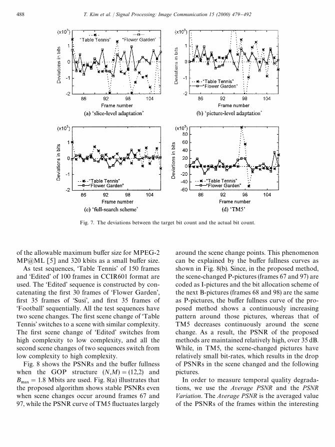
Fig. 7. The deviations between the target bit count and the actual bit count.
of the allowable maximum bu!er size for MPEG-2MP@ML [5] and 320 kbits as a small bu!er size.
As test sequences, &Table Tennis' of 150 framesand &Edited' of 100 frames in CCIR601 format areused. The &Edited' sequence is constructed by con-catenating the "rst 30 frames of &Flower Garden',"rst 35 frames of &Susi', and "rst 35 frames of&Football' sequentially. All the test sequences havetwo scene changes. The "rst scene change of &TableTennis' switches to a scene with similar complexity.The "rst scene change of &Edited' switches fromhigh complexity to low complexity, and all thesecond scene changes of two sequences switch fromlow complexity to high complexity.
Fig. 8 shows the PSNRs and the bu!er fullnesswhen the GOP structure (N,M)"(12,2) andB.!9
"1.8 Mbits are used. Fig. 8(a) illustrates thatthe proposed algorithm shows stable PSNRs evenwhen scene changes occur around frames 67 and97, while the PSNR curve of TM5 #uctuates largely
around the scene change points. This phenomenoncan be explained by the bu!er fullness curves asshown in Fig. 8(b). Since, in the proposed method,the scene-changed P-pictures (frames 67 and 97) arecoded as I-pictures and the bit allocation scheme ofthe next B-pictures (frames 68 and 98) are the sameas P-pictures, the bu!er fullness curve of the pro-posed method shows a continuously increasingpattern around those pictures, whereas that ofTM5 decreases continuously around the scenechange. As a result, the PSNR of the proposedmethods are maintained relatively high, over 35 dB.While, in TM5, the scene-changed pictures haverelatively small bit-rates, which results in the dropof PSNRs in the scene changed and the followingpictures.
In order to measure temporal quality degrada-tions, we use the Average PSNR and the PSNRVariation. The Average PSNR is the averaged valueof the PSNRs of the frames within the interesting
488 T. Kim et al. / Signal Processing: Image Communication 15 (2000) 479}492

Table 1The comparisons of average and maximum NADs among several schemes
Image sequences Average NAD Maximum NAD
&Slice' &Picture' &TM5' &Full' &Slice' &Picture' &TM5' &Full'
Table I 0.419 0.623 2.773 0.156 0.747 1.043 14.296 0.297Tennis P 0.188 0.245 3.936 0.132 0.794 0.709 37.757 0.824
B 0.351 0.377 6.216 0.288 1.428 2.444 51.225 1.026
Flower I 0.161 0.067 0.769 0.039 0.313 0.330 1.770 0.119Garden P 0.184 0.271 4.741 0.151 0.610 1.452 44.490 0.503
B 0.302 0.287 9.233 0.187 1.062 0.923 32.764 0.507
&Slice': &slice-level adaptation'; &Picture': &picture-level adaptation'; &Full': &full search scheme'; &TM5': &TM5' rate control.
Fig. 8. Using B.!9
"1.8 Mbits and GOP structure (12,2), the PSNR and bu!er fullness for &Table Tennis' with 6 Mbits/s.
Table 2The Average PSNR and the PSNR Variation for the &Proposed' rate control algorithm and TM5 scheme; the bu!er size is 1.8 Mbits
Statistics Average PSNR (dB) PSNR Variation (dB)Coding bit-rate (Mbits/s) 6 12 6 12
Whole Proposed 35.826 38.629 0.287 0.853Sequence TM5 35.113 38.053 0.833 1.782
First Proposed 35.988 38.836 0.390 1.024Scene Change TM5 34.865 37.889 1.026 2.164
Second Proposed 35.198 38.089 0.209 0.769Scene Change TM5 33.576 36.709 0.925 1.884
period and the PSNR Variation is de"ned as
PSNR Variation
"
1
¸!F#1
L+
f/F
DPSNRf~1
!PSNRfD, (22)
where F is the "rst frame number, ¸ is the lastframe number, and PSNR
fmeans the PSNR of
frame f. The results of Fig. 8 are summarized inTable 2. The &Whole Sequence' represents theframes corresponding to F"60 and ¸"120, in-cluding all scene changes. While the period of
T. Kim et al. / Signal Processing: Image Communication 15 (2000) 479}492 489

Fig. 9. Using B.!9
"320 kbits and GOP structure (12,2), the PSNR and bu!er fullness for &Table Tennis' with 6 Mbits/s.
Fig. 10. Using 12 Mbits/s and GOP structure (12,2), the PSNR and bu!er fullness for the &Edited' sequence.
&First Scene Change' is the consecutive 12 framesstarting from the "rst scene changed P-picture (i.e.F"67 and ¸"78), and the period of &SecondScene Change' is the consecutive 12 frames startingfrom the second scene changed P-picture (i.e.
F"97 and ¸"108). The Average PSNRs of theproposed algorithm are 0.5}0.7 dB higher for&Whole Sequence', 1 dB higher for &First SceneChange', and 1.3}1.5 dB higher for &Second SceneChange' comparing it with TM5. For &Whole
490 T. Kim et al. / Signal Processing: Image Communication 15 (2000) 479}492
Sequence', the PSNR Variation of the proposed al-gorithm is about 1/3}1/2 of TM5. Especially, thePSNR Variation of the proposed method is muchsmaller than those of TM5 for scene changes. Thismeans that the proposed method can maintain con-sistent picture quality even when the scene changes.
Fig. 9 shows the PSNR and bu!er fullness whena small bu!er size of 320 kbits is used. Although thebu!er size becomes smaller than that in Fig. 8, thebit-rates generated by TM5 (the dotted line inFig. 9(b)) are the same as in Fig. 8 (the dotted line inFig. 8(b)). As a result, bu!er over#ows occur severaltimes as shown in Fig. 9(b). These bu!er over#owscan be prevented by using a larger bu!er or bylowering the bit-rate. In the proposed rate controlalgorithm, the bu!er over#ows never occur asshown in Fig. 9(b). In the scene-changed picturesand some I-pictures (i.e. frames 67, 83, 95, 97 and107), the bit allocation is limited by the bu!erstatus. Additionally, the proposed algorithm con-trols strictly the bit-rate so that the generated bit-rate becomes similar to the allocated bit-rate.
Fig. 10 shows the coding results for the &Edited'sequence with GOP structure (N,M)"(12, 2) andconstant bit-rate 12 Mbits/s. The special points ofthe &Edited' sequence is that the "rst 30 frames ofthe &Flower Garden' have high complexity, the next35 frames of &Susi' have very low complexity, andthe last 35 frames of &Football' have high complex-ity. When the bu!er size is 1.8 Mbits (Fig. 10(a) and(c)), TM5 shows very large #uctuations in PSNRaround the scene changes and I-pictures (frames 30,31, 47, 59, 65, 66). When the bu!er size is as small as320 kbits (Fig. 10(b) and (d)), bu!er over#ows occurin these frames, seriously. However, in the proposedrate control algorithm bu!er over#ows do notoccur because the bit-rate is determined by consid-ering both the bu!er status and complexity.
5. Conclusions
In the bit-rate control of a video encoder, it isimportant to allocate the target bit count to eachpicture according to its complexity, as well as toencode to match the allocated number of bits asaccurately as possible. In this paper, we proposedan accurate bit-rate control algorithm based on the
linear relationship between the codeword countand the actual bit count. The model parameters forbit-rate estimation can be calculated in real timefrom the previous coding results. Also, the actualbit count by our scheme nearly matches the targetbit count. In addition, we proposed an e$cientbu!er control algorithm, which can not only main-tain a consistent visual quality even for scenechanges, but also control a bu!er e$ciently evenfor small bu!ers. The proposed bu!er control algo-rithm operates in real time with a constant picturedelay while conforming to the MPEG standard.
The high accuracy of the proposed bit-rate con-trol is accomplished by a pre-analysis with a pic-ture delay. For real-time applications, the encoderrequires some additional circuits, and higher pro-cessing speed than the TM5 MPEG encoder. Theseextra costs are only marginal for implementation ofa real-time processor and worth paying for accu-rate rate control. The proposed methods can beused for various purposes such as a constant bit-rate MPEG video encoder with a small bu!er,video encoder control for conformance of the nego-tiated tra$c descriptors in variable bit-rate trans-mission, or MPEG video recording and editing.
References
[1] J.H. Choi, D.C. Park, A stable feedback control of thebu!er state using the controlled Lagrange multipliermethod, IEEE Trans. Image Process. 3 (5) (September1994) 546}558.
[2] G. Cicalini, L. Favalli, A. Mecocci, Improving bit rate andquality control for MPEG-2 video sources, in: Proceedingsof EUSIPCO, 1996, pp. 735}738.
[3] W. Ding, B. Liu, Rate control of MPEG-2 video codingand recording by rate-quantization modeling, IEEETrans. Circuit Systems Video Technol. (June 1996) 12}20.
[4] E.D. Frimout, J. Biemond, R.L. Lagendijk, Forward ratecontrol for MPEG recording, in: Proceedings of SPIEVCIP, 1993, pp. 184}194.
[5] ISO-IEC/JTC1/SC29/WG11/N0801rev, Generic codingof moving pictures and associated audio: video, MPEGCommittee Draft: Rec. H.262, April 1995.
[6] S.H. Jang, S.H. Park, An adaptive rate control algorithmfor DPCM/DCT hybrid video codec adopting bi-direc-tional prediction, in: Proceedings of SPIE VCIP, 1993,pp. 1237}2094.
[7] W.Y. Lee, J.B. Ra, Fast algorithm for optimal bit alloca-tion in rate-distortion sense, Electron. Lett. 32 (September1996) 1871}1873.
T. Kim et al. / Signal Processing: Image Communication 15 (2000) 479}492 491

[8] L.J. Lin, A. Ortega, C.-C.J. Kuo, Gradient-based bu!ercontrol technique for MPEG, in: Proceedings of SPIEVCIP, Vol. 2501, 1995, pp. 1501}1513.
[9] MPEG-2: Test Model 5, Draft, ISO/IEC JTC1/SC29/WG11/N0400, April 1993.
[10] MPEG Software Simulation Group: MPEG-2 en-coder/decoder, version 1.1, 1994.
[11] A. Ortega, K. Ramchandran, M. Vetterli, Optimal trellis-based bu!ered compression and fast approximation, IEEETrans. Image Process. 3 (1) (1994) 26}40.
[12] K. Ramchandran, A. Ortega, M. Vetterli, Bit allocationfor dependent quantization with applications to MPEGvideo coders, in: Proceedings of IEEE ICASSP, 1993,pp. 381}384.
[13] P. Tiwari, E. Viscito, A parallel MPEG-2 video encoderwith look-ahead rate control, in: Proceedings of IEEEICASSP, 1996, pp. 1994}1997.
[14] L. Wang, Rate control for MPEG video coding,in: Proceedings of SPIE VCIP, Vol. 2501, 1995,pp. 53}64.
492 T. Kim et al. / Signal Processing: Image Communication 15 (2000) 479}492