an 603: active serial remote system upgrade … the pof_error output ... active serial remote system...
TRANSCRIPT

© August 2013 Altera Corporation
© August 2013
AN 603: Active Serial Remote SystemUpgrade Reference Design
AN-603-1.1
This application note provides a reference design for the active serial (AS) remote system upgrade feature in Arria II GX, Stratix III, and Stratix IV devices. The AS remote system upgrade feature enables supported Altera devices to receive new configuration data from a remote source, update of the flash memory content, and reconfigure the device with new configuration data, allowing you to overcome difficult challenges such as shorten design cycles, evolving standards, and system deployments in remote locations.
This reference design instantiates the ALTREMOTE_UPDATE megafunction and a user logic to initiate the reconfiguration cycle. Use this reference design to begin using the remote system upgrade feature in Arria II GX, Stratix III, and Stratix IV devices and then you can modify the design to suit your system usage.
This application note contains the following sections:
■ “Remote Update Mode” on page 2
■ “Functional Description” on page 3
■ “Factory Configuration Image User Logic State Machine” on page 10
■ “Application Configuration Image User Logic State Machine” on page 16
■ “Remote System Upgrade Reconfiguration” on page 19
■ “AS Remote System Upgrade Testing Procedure” on page 23
1 This reference design is targeted for Arria II GX devices. Because the remote system upgrade circuitry for Stratix III and Stratix IV devices are identical to the Arria II GX devices, this reference design is also applicable for these devices.
f For more information about the AS mode and remote system upgrade feature for Arria II GX, Stratix III, and Stratix IV devices, refer to the following chapters:
■ Configuration, Design Security, and Remote System Upgrades in Arria II GX Devices chapter in volume 1 of the Arria II GX Device Handbook.
■ Remote System Upgrades with Stratix III Devices chapter in volume 1 of the Stratix III Device Handbook.
■ Configuration, Design Security, and Remote System Upgrades in Stratix IV Devices chapter in volume 1 of the Stratix IV Device Handbook.
AN 603: Active Serial Remote System Upgrade Reference Design

Page 2 Remote Update Mode
Remote Update ModeWhen the device is first powered up in remote update mode, it loads the factory configuration located at page zero (page registers PGM[23..0] = 24’h000000). You must always store the factory configuration image for your system at page address zero. This corresponds to the start address of 0×000000 in the serial configuration device (EPCS).
After power up or a configuration error, the factory configuration logic automatically loads. The user-defined factory configuration determines which application configuration to load before triggering a reconfiguration cycle. The factory configuration also must specify whether to enable the user watchdog timer for the application configuration and, if enabled, to include the timer setting information as well.
Figure 1 shows the transition between the factory and application configuration image in remote update mode.
If an error occurs when the application configuration image is loading, the dedicated remote upgrade circuitry of your device updates the remote system upgrade status register with the error information. The following actions can cause the remote system upgrade status register to be written:
■ nSTATUS is driven low
■ Internal configuration cyclical redundancy check (CRC) error
■ Configuration reset from the logic array (core nCONFIG)
■ External nCONFIG assertion
■ User watchdog timer time out
After an error, the system reverts back to the factory configuration image. You can read the remote upgrade status register to determine the reconfiguration source and determine your next course of action.
Figure 1. Transition Between Configurations in Remote Update Mode
Factory Configuration
Application 1Configuration
Application and Configuration
Set Control Registerand Reconfigure
Configuration Error
Set Control Registerand Reconfigure
Configuration Error
Reload a Different Application
Reload a Different Application
Power Up
Configuration Error
AN 603: Active Serial Remote System Upgrade Reference Design © August 2013 Altera Corporation
Functional Description Page 3
When the device successfully loads the application configuration image, the soft logic in the application configuration image determines when the remote system update is arriving. When a remote system update arrives, the soft logic receives the incoming data, writes it to the memory configuration devices, and triggers the system to load the factory configuration image. The factory configuration image reads the remote system upgrade status register, determines the valid application configuration image to load, writes the remote system upgrade control register, and initiates system reconfiguration.
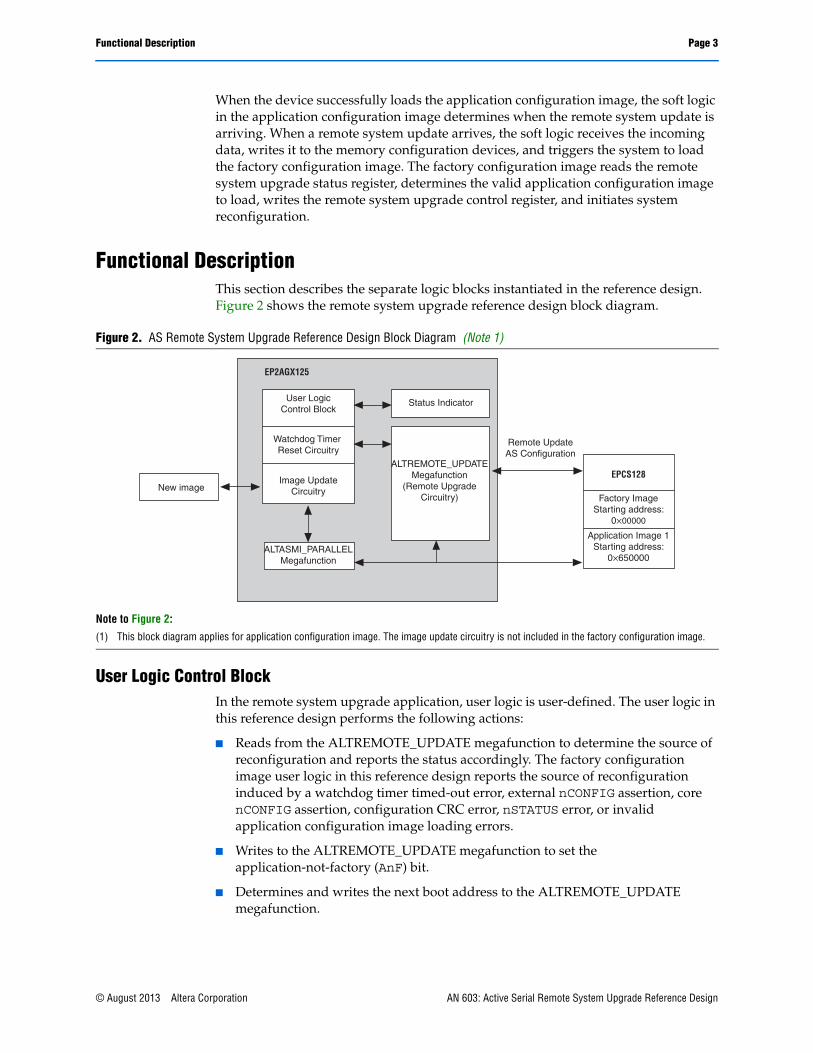
Functional DescriptionThis section describes the separate logic blocks instantiated in the reference design. Figure 2 shows the remote system upgrade reference design block diagram.
User Logic Control BlockIn the remote system upgrade application, user logic is user-defined. The user logic in this reference design performs the following actions:
■ Reads from the ALTREMOTE_UPDATE megafunction to determine the source of reconfiguration and reports the status accordingly. The factory configuration image user logic in this reference design reports the source of reconfiguration induced by a watchdog timer timed-out error, external nCONFIG assertion, core nCONFIG assertion, configuration CRC error, nSTATUS error, or invalid application configuration image loading errors.
■ Writes to the ALTREMOTE_UPDATE megafunction to set the application-not-factory (AnF) bit.
■ Determines and writes the next boot address to the ALTREMOTE_UPDATE megafunction.
Figure 2. AS Remote System Upgrade Reference Design Block Diagram (Note 1)
Note to Figure 2:
(1) This block diagram applies for application configuration image. The image update circuitry is not included in the factory configuration image.
Status Indicator
ALTASMI_PARALLELMegafunction
EP2AGX125
User LogicControl Block
Watchdog Timer Reset Circuitry
Image UpdateCircuitryNew image
ALTREMOTE_UPDATEMegafunction
(Remote UpgradeCircuitry)
EPCS128
Factory ImageStarting address:
0×00000
Application Image 1Starting address:
0×650000
Remote UpdateAS Configuration
© August 2013 Altera Corporation AN 603: Active Serial Remote System Upgrade Reference Design
Page 4 Functional Description
■ Writes to the ALTREMOTE_UPDATE megafunction to enable the watchdog timer feature in the application configuration image.
■ Writes to the ALTREMOTE_UPDATE megafunction to set the watchdog timer value for the application configuration image.
■ Triggers the ALTREMOTE_UPDATE megafunction to initiate the reconfiguration.
■ Monitors the pof_error output from the ALTREMOTE_UPDATE megafunction and determines the next course of action based on the pof_error status.
The following are the functions of the user logic in the application configuration image:
■ Reads from the ALTREMOTE_UPDATE megafunction to determine the current status of the watchdog timer feature.
■ Reads from the ALTREMOTE_UPDATE megafunction to determine the value of the watchdog timer time out.
■ Triggers the ALTREMOTE_UPDATE megafunction to initiate the reconfiguration.
ALTREMOTE_UPDATE MegafunctionThe ALTREMOTE_UPDATE megafunction in the Quartus II software allows you to take advantage of the remote upgrade circuitry in Arria II GX, Stratix III, and Stratix IV devices. The ALTREMOTE_UPDATE megafunction simplifies the user interface of the dedicated remote upgrade circuitry, allowing you to implement the remote system upgrade feature with the following features:
■ Factory image configuration
■ Application image configuration
■ Watchdog timer
f For more information about the ALTREMOTE_UPDATE megafunction, refer to the Remote Update Circuitry (ALTREMOTE_UPDATE) Megafunction User Guide.
The Enable Reconfig POF Checking OptionFor Arria II GX, Stratix III, and Stratix IV devices, the ALTREMOTE_UPDATE megafunction includes a reconfiguration programmer object file (.pof) checking feature. To ensure a robust remote system upgrade operation, Altera recommends enabling this feature in the factory configuration image. You can disable the Enable reconfig POF checking option in the application configuration image.
To enable the Enable reconfig POF checking option from the Quartus II software, turn on Enable reconfig POF checking in the ALTREMOTE_UPDATE MegaWizard Plug-In Manager dialog box (Figure 3).
AN 603: Active Serial Remote System Upgrade Reference Design © August 2013 Altera Corporation

Functional Description Page 5
The Enable reconfig POF checking option allows the remote update block to verify the existence of an application configuration image before the image is loaded. Image verification is accomplished by reading the content of the serial configuration device (EPCS) at the specified application configuration image start address. To allow the ALTREMOTE_UPDATE megafunction to read and verify the content of the EPCS, you must instantiate the ALTASMI_PARALLEL megafunction into your design. If the application configuration image contains an invalid image, the ALTREMOTE_UPDATE megafunction asserts the pof_error output pin high to indicate the error. An invalid image can be a blank image or a partially programmed application configuration image. When the pof_error output pin is asserted, you must re-write a new image into the specified location in the EPCS or you must specify a different address location containing a valid application configuration image.
If this feature is enabled, four additional outputs and three additional inputs are introduced on the ALTREMOTE_UPDATE megafunction block.
Figure 3. Enable Reconfig POF Checking Option
© August 2013 Altera Corporation AN 603: Active Serial Remote System Upgrade Reference Design

Page 6 Functional Description
Table 1 lists the additional ALTREMOTE_UPDATE megafunction inputs and outputs needed if you enabled the Enable reconfig POF checking option.
1 For more information about using the pof_error output pin and instantiating this pin inside your design, refer to the “Factory Configuration Image User Logic State Machine” on page 10.
Table 1. Additional Inputs and Outputs on the ALTREMOTE_UPDATE Megafunction Block for the Enable Reconfig POF Checking Option
I/O Port Type Description
asmi_busy Input
A logic high on this pin indicates that the ALTASMI_PARALLEL megafunction is busy processing the operation.
The ALTREMOTE_UPDATE megafunction waits for this pin to go low before initiating another operation.
Wire this pin to the asmi_busy output port of the ALTASMI_PARALLEL megafunction.
asmi_data_valid Input
A logic high on this pin indicates that there is valid data in the asmi_dataout[7..0] output port of the ALTASMI_PARALLEL megafunction.
Wire this pin to the asmi_data_valid output port of the ALTASMI_PARALLEL megafunction.
asmi_dataout[7..0] Input
The ALTASMI_PARALLEL megafunction presents valid data on this pin after a read operation is complete.
Wire this pin to the asmi_dataout[7..0] output port of the ALTASMI_PARALLEL megafunction.
asmi_addr[23..0] Output
The ALTREMOTE_UPDATE megafunction presents the address information on this pin before initiating the read operation on the ALTASMI_PARALLEL megafunction.
Wire this pin to the asmi_addr[23..0] input port of the ALTASMI_PARALLEL megafunction.
asmi_read Output
A logic high on this pin initiates the read operation on the ALTASMI_PARALLEL megafunction.
Wire this pin to the asmi_read input port of the ALTASMI_PARALLEL megafunction.
asmi_rden Output
This pin enables the read operation on the ALTASMI_PARALLEL megafunction.
Wire this pin to the asmi_rden input port of the ALTASMI_PARALLEL megafunction.
pof_error Output
A logic high on this pin indicates that the ALTREMOTE_UPDATE megafunction detects an invalid application configuration image. If asserted high, you must take corrective action by reloading a new application configuration image or specifying a different address location in the EPCS that contains a valid application configuration image. Wire this pin based on your system requirement.
AN 603: Active Serial Remote System Upgrade Reference Design © August 2013 Altera Corporation
Functional Description Page 7
1 The ALTREMOTE_UPDATE megafunction must be able to access to the ALTASMI_PARALLEL megafunction when the reconfig input is first triggered until the busy signal is pulled low. If your design contains another logic that must access the ALTASMI_PARALLEL megafunction for other purposes; for example, to update the EPCS content, you must multiplex the outputs between this logic and the outputs from the ALTREMOTE_UPDATE megafunction that feed the ALTASMI_PARALLEL megafunction. You can find the verilog code example in the reference design folder with the name multiplexer.v.
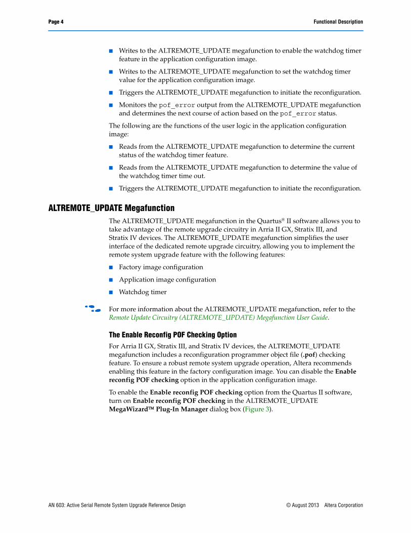
Image Update CircuitryTo emulate a real application where you can update a new application after the device is in user mode, the application configuration image in this reference design includes an image update circuitry that reads a new image from a different memory location and writes the new image into the specified location inside the EPCS. Figure 4 shows a block diagram of the image update circuitry.
The image update circuitry includes two different logics—a controller logic that reads a new image from a parallel flash and an update logic that writes a new image into the EPCS at 0900000 byte address with the ALTASMI_PARALLEL megafunction interface. After the image update is completed, the application configuration image user logic triggers the reconfiguration back to the factory configuration image. The factory configuration image user logic verifies the reconfiguration source condition and triggers the reconfiguration to load the new updated image from the new location.
1 To begin the image update, keep the vcontroller_reset input pin at logic low. This input pin is tied to the controller logic within the image update circuitry. To de-activate image update circuitry, keep the vcontroller_reset input pin at logic high.
Figure 4. Block Diagram of the Image Update Circuitry
Note to Figure 4:
(1) vcontroller_reset is routed to an external I/O. You will need external triggering to set a logic high or logic low on this input.
ControllerLogic
UpdateLogic
ALTASMI_PARALLELMegafunction
Application Image
Remote Update Circuitry
ParallelFlash
EPCS
vcontroller_reset (1)
© August 2013 Altera Corporation AN 603: Active Serial Remote System Upgrade Reference Design

Page 8 Functional Description
Watchdog Timer Reset CircuitryThe watchdog timer circuitry in the remote system upgrade feature ensures that the application configuration image is valid and functional. In this reference design, the watchdog timer reset circuitry resets the timer periodically during user-mode operation of an application configuration image. This operation indicates that the system is running error-free. If the application configuration image detects a functional problem or if the system hangs, the watchdog timer reset circuitry fails to function and the timer fails to reset. The watchdog timer times out and the dedicated circuitry updates the remote system upgrade status register, triggering the device to load the factory configuration image.
With the ALTREMOTE_UPDATE megafunction, the time-out value for the watchdog timer circuitry is set to 40,894,464 clock cycles, based on the internal 10-MHz clock that is supplied from the remote system upgrade feature. The time-out value is set during factory image configuration. To reset the watchdog timer before it expires, use the watchdog timer reset circuitry in the application configuration image. The watchdog timer reset circuitry is designed to reset the timer for every 33,554,432 clock cycles, based on the external 10-MHz clock source.
ALTASMI_PARALLEL MegafunctionThe ALTASMI_PARALLEL megafunction implements a basic Active Serial Memory Interface (ASMI) block. This megafunction provides access to the EPCS device memory through parallel data input and output ports. With this megafunction, you can perform the following functions:
■ Specify the type of EPCS to use
■ Read the EPCS silicon identification
■ Protect a certain sector in the EPCS device from write or erase
■ Read the data at a specified address from the EPCS device
■ Perform single-byte writes to the EPCS
■ Perform page writes to the EPCS
■ Read the status of the EPCS device
■ Erase a certain sector on the EPCS device
■ Erase all the memory on the EPCS device
1 For more information about the ALTASMI_PARALLEL megafunction, refer to the Active Serial Memory Interface (ALTASMI_PARALLEL) Megafunction User Guide.
AN 603: Active Serial Remote System Upgrade Reference Design © August 2013 Altera Corporation
Functional Description Page 9
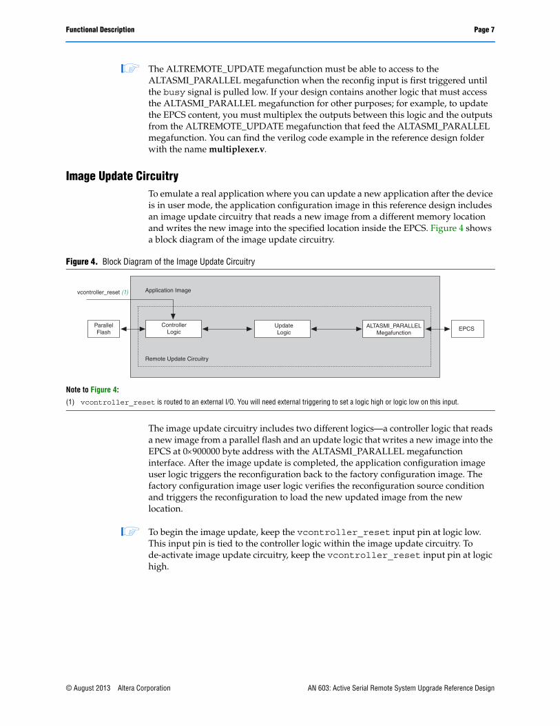
Status IndicatorThis reference design has one factory configuration image and one application configuration image. The factory configuration image user logic reports the reconfiguration source that is triggered by a watchdog timer time-out error, external nCONFIG assertion, core nCONFIG assertion, configuration CRC error, nSTATUS error, or an invalid application configuration image loading error. The factory configuration image user logic turns on or turns off the three available LEDs in a different combination to indicate system status.
Table 2 lists the system status information for different combinations of the LED[2..0] status.
Table 2. Status Indicator Description (Note 1)
LED[2..0] Status Information
3’b111 The factory configuration image is loaded after power up.
3’b000 The factory configuration image is loaded after an nSTATUS error during the application image configuration.
3’b010 The factory configuration image is loaded after a CRC error during the application image configuration.
3’b101 The factory configuration image is loaded after a core nCONFIG assertion during the application image configuration.
3’b001 The factory configuration image is loaded after an external nCONFIG assertion during the application image configuration.
3’b110 The factory configuration image is loaded after a watchdog timer timed out an error during the application image configuration.
3’bX00 The factory configuration image has observed an attempt to load an invalid application configuration image during the application image configuration.
3’bX1X The application configuration image is loaded. LED[2] and LED[0] blinks to indicate that the watchdog timer reset circuitry is continuously resetting the watchdog timer. The image update circuitry is idle.
3’bXXXThe application configuration image is loaded. LED[2] and LED[0] blinks to indicate that the watchdog timer reset circuitry is continuously resetting the watchdog timer. LED[1] blinks to indicate that the image update circuitry is running.
Note to Table 2:
(1) ‘1’ indicates the LED is turned on. ‘0’ indicates the LED is turned off. ‘X’ indicates the LED is blinking.
© August 2013 Altera Corporation AN 603: Active Serial Remote System Upgrade Reference Design
Page 10 Factory Configuration Image User Logic State Machine
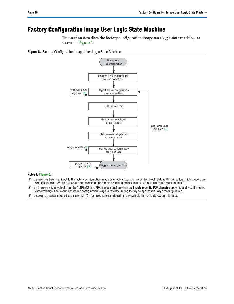
Factory Configuration Image User Logic State MachineThis section describes the factory configuration image user logic state machine, as shown in Figure 5.
Figure 5. Factory Configuration Image User Logic State Machine
Notes to Figure 5:
(1) Start_write is an input to the factory configuration image user logic state machine control block. Setting this pin to logic high triggers the user logic to begin writing the system parameters to the remote system upgrade circuitry before initiating the reconfiguration.
(2) Pof_error is an output from the ALTREMOTE_UPDATE megafunction when the Enable reconfig POF checking option is enabled. This output is asserted high if an invalid application configuration image is detected during factory-to-application image reconfiguration.
(3) Image_update is routed to an external I/O. You need external triggering to set a logic high or logic low on this input.
Power-up/Reconfiguration
Read the reconfigurationsource condition
Report the reconfigurationsource condition
Set the AnF bit
Enable the watchdogtimer feature
Set the watchdog timertime-out value
Set the application imagestart address
Trigger reconfiguration
pof_error is atlogic high (2)
pof_error is atlogic low (2)
start_write is atlogic low (1)
image_update (3)
AN 603: Active Serial Remote System Upgrade Reference Design © August 2013 Altera Corporation

Factory Configuration Image User Logic State Machine Page 11
Reading the Reconfiguration Source ConditionEvery time the system loads a factory configuration image, you can read the reconfiguration source trigger condition. This allows you to determine whether an error has occurred during application image configuration or when the system loads the factory configuration image for the first time after power up.
To read the reconfiguration trigger condition, the user logic issues param = 3’b000 and read_param = 1’b1 to the ALTREMOTE_UPDATE megafunction. On the rising edge of the clock, ALTREMOTE_UPDATE asserts the busy signal high to indicate the remote upgrade circuitry is busy processing the operation. When the busy signal goes low, it indicates the reading operation is complete and valid data is presented on the data_out output of the ALTREMOTE_UPDATE megafunction.
Figure 6 shows a screenshot of the read reconfiguration source condition operation in the SignalTap II Logic Analyzer. The sample clock frequency in Figure 6 is 20 MHz.
As shown in Figure 6, the reconfiguration source status from the ALTREMOTE_UPDATE megafunction is 24’h08 (5’b01000), indicating the factory configuration image is loaded after external nCONFIG is asserted in the application configuration image.
f For more information about the reconfiguration source condition, refer to the Configuration, Design Security, and Remote System Upgrades in Arria II GX Devices chapter in volume 1 of the Arria II GX Device Handbook.
For more information, refer to the “Remote System Upgrade Reconfiguration” on page 19.
Figure 6. Read Reconfiguration Source Condition Operation as Viewed with the SignalTap II Logic Analyzer (Note 1)
Note to Figure 6:
(1) After the operation completes, the ALTREMOTE_UPDATE megafunction returns to 24’h08 on data_out_node.
© August 2013 Altera Corporation AN 603: Active Serial Remote System Upgrade Reference Design

Page 12 Factory Configuration Image User Logic State Machine
Reporting the Reconfiguration Source ConditionAfter reading the reconfiguration source trigger condition, the user logic in the factory configuration image reports the system status, as listed in Table 2 on page 9. The factory configuration image state machine stays in this state until the start_write input is asserted high to trigger the factory configuration image to begin writing to the ALTREMOTE_UPDATE megafunction and trigger the reconfiguration to the application configuration image.
Setting the AnF Bit OperationIn remote update mode, the AnF bit is not automatically set. You need to set the AnF bit to 1’b1 before triggering the reconfiguration to the application configuration image.
To set the AnF bit, the user logic issues param = 3’b101, data_in = 24’h000001, and write_param = 1’b1 to the ALTREMOTE_UPDATE megafunction. On the rising edge of the clock, the ALTREMOTE_UPDATE megafunction asserts the busy signal high to indicate the remote upgrade circuitry is busy processing the operation. The busy signal goes low when the operation completes.
Figure 7 shows a screenshot of the set AnF bit operation in the SignalTap II Logic Analyzer. The sample clock frequency in Figure 7 is 20 MHz.
Enabling the Watchdog Timer FeatureThe watchdog timer feature is an optional feature that helps you determine the validity and functionality of the application configuration image.
To enable the watchdog timer feature, user logic issues param = 3’b011, data_in = 24’h000001, and write_param = 1’b1 to the ALTREMOTE_UPDATE megafunction. On the rising edge of the clock, the ALTREMOTE_UPDATE megafunction asserts the busy signal high to indicate the remote upgrade circuitry is busy processing the operation. The busy signal goes low when the operation is completed.
Figure 8 shows a screenshot of the enable watchdog timer feature operation in the SignalTap II Logic Analyzer. The sample clock frequency in Figure 8 is 20 MHz.
Figure 7. Setting AnF Bit Operation as Viewed with the SignalTap II Logic Analyzer
AN 603: Active Serial Remote System Upgrade Reference Design © August 2013 Altera Corporation

Factory Configuration Image User Logic State Machine Page 13
1 If you do not wish to use this feature, you can disable the feature by setting param_node to 3’b011, data_in_node to 24’000000, and write_param_node to 1’b0.
Setting the Watchdog Timer Time-Out ValueAfter you have enabled the watchdog timer feature, you must set the watchdog timer time-out value based on the internal 10-MHz clock. Specify the first 12 upper bits of the 29-bits watchdog timer time-out value. The remote upgrade circuitry sets the remaining lower 17 bits of the 29-bits watchdog timer time-out value to zero.
In this reference design, the watchdog timer is set to 40,894,464 clock cycles, based on the internal 10-MHz clock. To accomplished this, the user logic issues param = 3’b010, data_in = 24’h000138, and write_param = 1’b1 to the ALTREMOTE_UPDATE megafunction. On the rising edge of the clock, the ALTREMOTE_UPDATE megafunction asserts the busy signal high to indicate the remote upgrade circuitry is busy processing the operation. The busy signal goes low when the operation is completed.
Figure 9 shows a screenshot of how you can set the watchdog timer time-out value operation in the SignalTap II Logic Analyzer. The sample clock frequency in Figure 9 is 20 MHz.
Figure 8. Enabling the Watchdog Timer Feature Operation as Viewed with the SignalTap II Logic Analyzer
Figure 9. Setting Watchdog Timer Time-Out Value Operation as Viewed with the SignalTap II Logic Analyzer
© August 2013 Altera Corporation AN 603: Active Serial Remote System Upgrade Reference Design

Page 14 Factory Configuration Image User Logic State Machine
Setting the Application Configuration Image AddressBefore you trigger the reconfiguration to the application configuration image, you must issue the application configuration image start address to the remote upgrade circuitry during the factory configuration image operation. If you choose to load the application configuration image at 0650000 byte address in the EPCS, then you must issue 0650000 to the remote upgrade circuitry.
To set the application configuration image start address to 0650000, the user logic issues param = 3’b100, data_in = 24’h650000, and write_param = 1’b1 to the ALTREMOTE_UPDATE megafunction. On the rising edge of the clock, the ALTREMOTE_UPDATE megafunction asserts the busy signal high to indicate the remote upgrade circuitry is busy processing the operation. The busy signal goes low when the operation is completed.
Figure 10 shows a screenshot on the setting of the application configuration image start address operation in the SignalTap II Logic Analyzer. The sample clock frequency in Figure 10 is 20 MHz.
Triggering the ReconfigurationAfter all the parameters are correctly written, you can initiate a reconfiguration to the application configuration image by asserting the reconfig input of the ALTREMOTE_UPDATE megafunction high. This is equivalent to triggering the reconfiguration from the core nCONFIG. If you enabled the Enable reconfig POF checking option, the ALTREMOTE_UPDATE megafunction asserts the busy signal high to indicate the remote upgrade circuitry is busy processing the operation. The ALTREMOTE_UPDATE megafunction reads the first frame of the image from the specified location inside the EPCS to determine the existence of a valid application configuration image.
If a valid application configuration image is available at the specified location, the ALTREMOTE_UPDATE megafunction triggers the remote update circuitry to load the application configuration image. Otherwise, the ALTREMOTE_UPDATE megafunction asserts the pof_error output high to indicate an error. After an error is reported, the remote update circuitry stays in the same factory configuration image and aborts the application configuration image reconfiguration. Accordingly, the user logic asserts the app_loading_error output pin high to indicate system status.
Figure 10. Set the Application Configuration Image Start Address Operation as Viewed with the SignalTap II Logic Analyzer
AN 603: Active Serial Remote System Upgrade Reference Design © August 2013 Altera Corporation

Factory Configuration Image User Logic State Machine Page 15
To recover from the error, replace the invalid application configuration image with a valid image and trigger another reconfiguration cycle using the ALTREMOTE_UPDATE megafunction.
Figure 11 shows a screenshot of the trigger reconfiguration operation in the SignalTap II Logic Analyzer. The sample clock frequency in Figure 11 is 20 MHz.
Figure 11. Set the Trigger Reconfiguration Operation as Viewed with the SignalTap II Logic Analyzer (Note 1), (2)
Notes to Figure 11:
(1) For this operation, the Enable reconfig POF checking option is enabled. For more information about the Enable reconfig POF checking option, refer to “The Enable Reconfig POF Checking Option” on page 4.
(2) To trigger the reconfiguration, assert the reconfig input signal to logic high for a minimum of 250 ns. This triggers the ALTREMOTE_UPDATE megafunction to read from the specified application configuration image address inside the EPCS and determine whether a valid FPGA image is present.
© August 2013 Altera Corporation AN 603: Active Serial Remote System Upgrade Reference Design

Page 16 Application Configuration Image User Logic State Machine
Application Configuration Image User Logic State MachineThis section describes the application configuration image user logic state machine. Figure 12 shows the factory configuration image user logic state machine.
Reading the Watchdog Timer Enable StatusTo validate the read watchdog timer enable status as set in the factory configuration image, you can read the watchdog timer enable status in the targeted application configuration image.
To read the watchdog timer enable status, the user logic issues param = 3’b011 and read_param = 1’b1 to the ALTREMOTE_UPDATE megafunction. On the rising edge of the clock, the ALTREMOTE_UPDATE megafunction asserts the busy signal high to indicate the remote upgrade circuitry is busy processing the operation. After the busy signal goes low, it indicates the reading operation is complete and valid data is present on the data_out output of the ALTREMOTE_UPDATE megafunction.
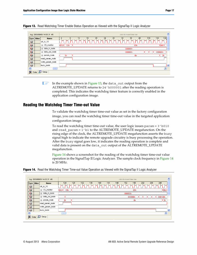
Figure 13 shows a screenshot for the read watchdog timer enable status operation in the SignalTap II Logic Analyzer. The sample clock frequency in Figure 13 is 20 MHz.
Figure 12. Application Configuration Image User Logic State Machine
Notes to Figure 12:
(1) Start_write is an input to the application configuration image user logic state machine control block. Setting this pin to logic high triggers the user logic to begin writing the system parameters to the remote system upgrade circuitry before initiating the reconfiguration.
(2) These operations are optional. If you do not want to read the watchdog timer setting or the AnF bit setting, you do not have to instantiate this operation in your application configuration image design.
Reconfiguration
Idle
Read the watchdog timerenable status
Read the watchdog timertime-out value
Read the AnF bit
Trigger reconfiguration
start_write is atlogic low (1)
start_write is atlogic high (1)
(2)
(2)
(2)
AN 603: Active Serial Remote System Upgrade Reference Design © August 2013 Altera Corporation
Application Configuration Image User Logic State Machine Page 17
1 In the example shown in Figure 13, the data_out output from the ALTREMOTE_UPDATE returns to 24’h000001 after the reading operation is completed. This indicates the watchdog timer feature is correctly enabled in the application configuration image.
Reading the Watchdog Timer Time-out ValueTo validate the watchdog timer time-out value as set in the factory configuration image, you can read the watchdog timer time-out value in the targeted application configuration image.
To read the watchdog timer time-out value, the user logic issues param = 3’b010 and read_param = 1’b1 to the ALTREMOTE_UPDATE megafunction. On the rising edge of the clock, the ALTREMOTE_UPDATE megafunction asserts the busy signal high to indicate the remote upgrade circuitry is busy processing the operation. After the busy signal goes low, it indicates the reading operation is complete and valid data is present on the data_out output of the ALTREMOTE_UPDATE megafunction.
Figure 14 shows a screenshot for the reading of the watchdog timer time-out value operation in the SignalTap II Logic Analyzer. The sample clock frequency in Figure 14 is 20 MHz.
Figure 13. Read Watchdog Timer Enable Status Operation as Viewed with the SignalTap II Logic Analyzer
Figure 14. Read the Watchdog Timer Time-out Value Operation as Viewed with the SignalTap II Logic Analyzer
© August 2013 Altera Corporation AN 603: Active Serial Remote System Upgrade Reference Design
Page 18 Application Configuration Image User Logic State Machine
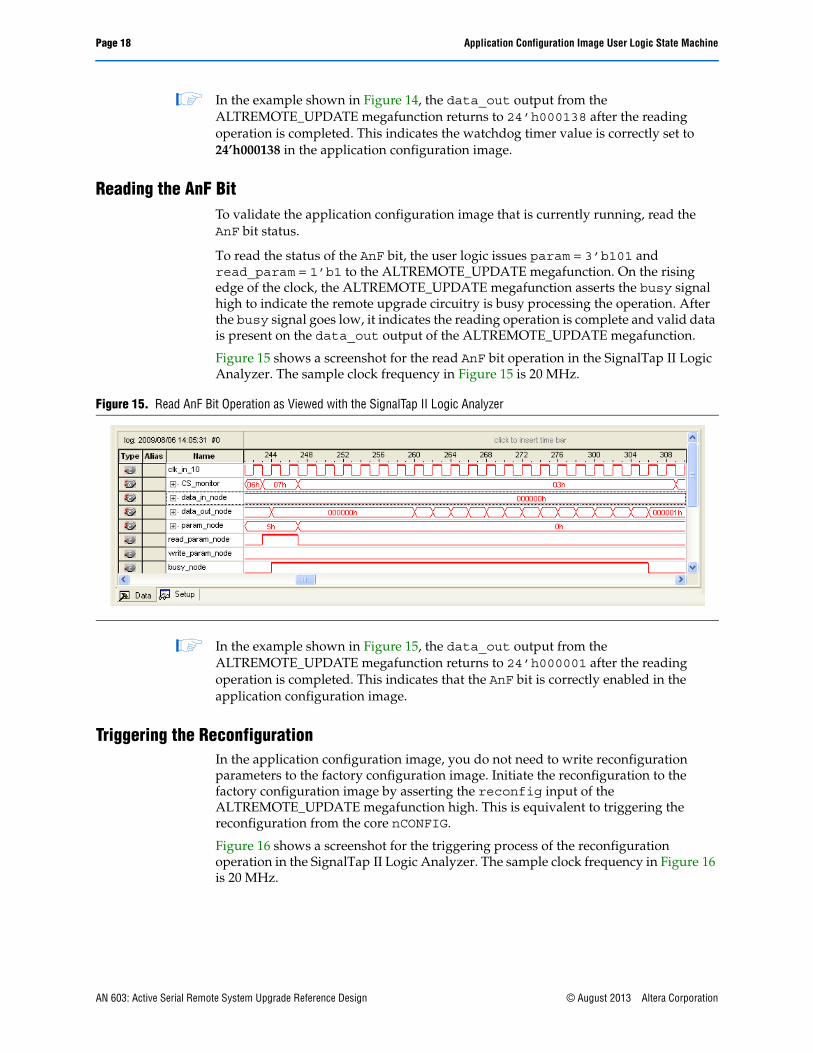
1 In the example shown in Figure 14, the data_out output from the ALTREMOTE_UPDATE megafunction returns to 24’h000138 after the reading operation is completed. This indicates the watchdog timer value is correctly set to 24’h000138 in the application configuration image.
Reading the AnF BitTo validate the application configuration image that is currently running, read the AnF bit status.
To read the status of the AnF bit, the user logic issues param = 3’b101 and read_param = 1’b1 to the ALTREMOTE_UPDATE megafunction. On the rising edge of the clock, the ALTREMOTE_UPDATE megafunction asserts the busy signal high to indicate the remote upgrade circuitry is busy processing the operation. After the busy signal goes low, it indicates the reading operation is complete and valid data is present on the data_out output of the ALTREMOTE_UPDATE megafunction.
Figure 15 shows a screenshot for the read AnF bit operation in the SignalTap II Logic Analyzer. The sample clock frequency in Figure 15 is 20 MHz.
1 In the example shown in Figure 15, the data_out output from the ALTREMOTE_UPDATE megafunction returns to 24’h000001 after the reading operation is completed. This indicates that the AnF bit is correctly enabled in the application configuration image.
Triggering the ReconfigurationIn the application configuration image, you do not need to write reconfiguration parameters to the factory configuration image. Initiate the reconfiguration to the factory configuration image by asserting the reconfig input of the ALTREMOTE_UPDATE megafunction high. This is equivalent to triggering the reconfiguration from the core nCONFIG.
Figure 16 shows a screenshot for the triggering process of the reconfiguration operation in the SignalTap II Logic Analyzer. The sample clock frequency in Figure 16 is 20 MHz.
Figure 15. Read AnF Bit Operation as Viewed with the SignalTap II Logic Analyzer
AN 603: Active Serial Remote System Upgrade Reference Design © August 2013 Altera Corporation

Remote System Upgrade Reconfiguration Page 19
Remote System Upgrade ReconfigurationIf an error is detected while loading the application configuration image, the remote system upgrade circuitry recovers from the error by writing to the remote system upgrade status registers and reloading the factory configuration image located at page 0 (page registers PGM[23..0] = 24’h000000). The remote system upgrade circuitry is able to recover from the following error conditions:
■ nSTATUS error during configuration
■ Internal configuration CRC error
■ Core nCONFIG assertion
■ External nCONFIG assertion
■ User watchdog timer time-out
The remote system upgrade status register is 5 bits in length. Each bit position represents one error condition. To read the remote system upgrade status register, the user logic reads the reconfiguration source condition parameter with the ALTREMOTE_UPDATE megafunction. Figure 17 shows the remote system upgrade status register content.
Figure 16. Trigger the Reconfiguration Operation as Viewed with the SignalTap II Logic Analyzer (Note 1), (2)
Notes to Figure 16:
(1) To trigger the reconfiguration, assert the reconfig input signal to logic high for a minimum of 250 ns.(2) Because the Enable reconfig POF checking option is not enabled in the application configuration image, the ALTREMOTE_UPDATE megafunction
busy signal remains low after the reconfig input is asserted and the FPGA reconfigures back to the factory configuration image at address 24’h000000.
Figure 17. Remote System Upgrade Status Register Content
Wd nCONFIG Core_nCONFIG nSTATUS CRC
34 2 1 0
© August 2013 Altera Corporation AN 603: Active Serial Remote System Upgrade Reference Design
Page 20 Remote System Upgrade Reconfiguration
1 You can monitor the remote system upgrade register content by reading the parameter of the reconfiguration source condition through the ALTREMOTE_UPDATE megafunction, as described in “Reading the Reconfiguration Source Condition” on page 11.
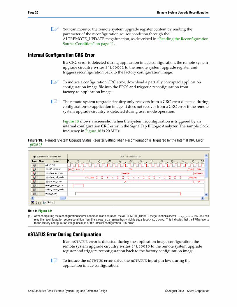
Internal Configuration CRC ErrorIf a CRC error is detected during application image configuration, the remote system upgrade circuitry writes 5’b00001 to the remote system upgrade register and triggers reconfiguration back to the factory configuration image.
1 To induce a configuration CRC error, download a partially corrupted application configuration image file into the EPCS and trigger a reconfiguration from factory-to-application image.
1 The remote system upgrade circuitry only recovers from a CRC error detected during configuration-to-application image. It does not recover from a CRC error if the remote system upgrade circuitry is detected during user mode operation.
Figure 18 shows a screenshot when the system reconfiguration is triggered by an internal configuration CRC error in the SignalTap II Logic Analyzer. The sample clock frequency in Figure 18 is 20 MHz.
nSTATUS Error During ConfigurationIf an nSTATUS error is detected during the application image configuration, the remote system upgrade circuitry writes 5’b00010 to the remote system upgrade register and triggers reconfiguration back to the factory configuration image.
1 To induce the nSTATUS error, drive the nSTATUS input pin low during the application image configuration.
Figure 18. Remote System Upgrade Status Register Setting when Reconfiguration is Triggered by the Internal CRC Error (Note 1)
Note to Figure 18:
(1) After completing the reconfiguration source condition read operation, the ALTREMOTE_UPDATE megafunction asserts busy_node low. You can read the reconfiguration source condition from the data_out_node bus which is equal to 24’h000001. This indicates that the FPGA reverts to the factory configuration image because of the internal configuration CRC error.
AN 603: Active Serial Remote System Upgrade Reference Design © August 2013 Altera Corporation

Remote System Upgrade Reconfiguration Page 21
Figure 19 shows a screenshot when the system reconfiguration is triggered by an internal nSTATUS error in the SignalTap II Logic Analyzer. The sample clock frequency in Figure 19 is 20 MHz.
Core nCONFIG AssertionIf a core nCONFIG is triggered in the application configuration image, the remote system upgrade circuitry writes 5’b00100 to the remote system upgrade register and triggers reconfiguration back to the factory configuration image.
1 Triggering the core nCONFIG is equivalent to asserting the reconfig input to the ALTREMOTE_UPDATE megafunction.
Figure 20 shows a screenshot when the system reconfiguration is triggered by the core nCONFIG assertion in the SignalTap II Logic Analyzer. The sample clock frequency in Figure 20 is 20 MHz.
Figure 19. Remote System Upgrade Status Register Setting when Reconfiguration is Triggered by the nSTATUS Error (Note 1)
Note to Figure 19:
(1) After completing the reconfiguration source condition read operation, the ALTREMOTE_UPDATE megafunction asserts busy_node low. You can read the reconfiguration source condition from the data_out_node bus which is equal to 24’h000002. This indicates that the FPGA reverts to the factory configuration image because of the internal configuration CRC error.
Figure 20. Remote System Upgrade Status Register Setting when Reconfiguration is Triggered by the Core nCONFIG Assertion (Note 1)
Note to Figure 20:
(1) After completing the reconfiguration source condition read operation, the ALTREMOTE_UPDATE megafunction asserts busy_node low. You can read the reconfiguration source condition from the data_out_node bus which is equal to 24’h000004. This indicates that the FPGA reverts to the factory because of the core nCONFIG assertion.
© August 2013 Altera Corporation AN 603: Active Serial Remote System Upgrade Reference Design
Page 22 Remote System Upgrade Reconfiguration
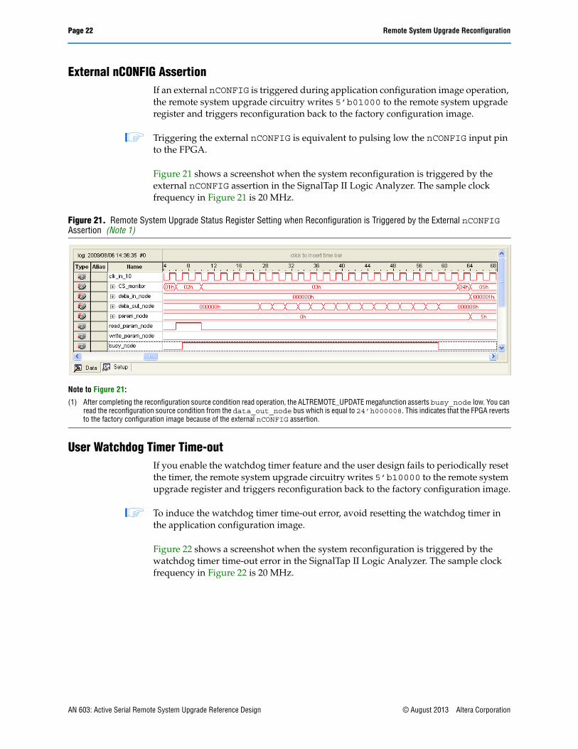
External nCONFIG AssertionIf an external nCONFIG is triggered during application configuration image operation, the remote system upgrade circuitry writes 5’b01000 to the remote system upgrade register and triggers reconfiguration back to the factory configuration image.
1 Triggering the external nCONFIG is equivalent to pulsing low the nCONFIG input pin to the FPGA.
Figure 21 shows a screenshot when the system reconfiguration is triggered by the external nCONFIG assertion in the SignalTap II Logic Analyzer. The sample clock frequency in Figure 21 is 20 MHz.
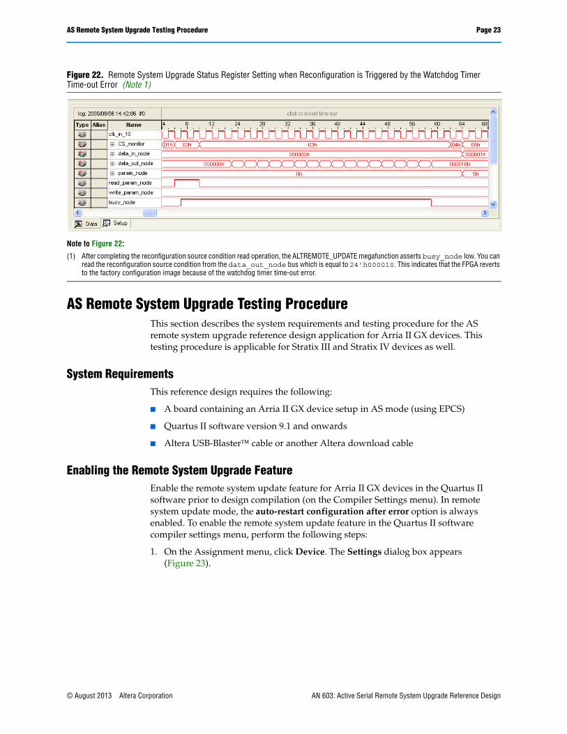
User Watchdog Timer Time-outIf you enable the watchdog timer feature and the user design fails to periodically reset the timer, the remote system upgrade circuitry writes 5’b10000 to the remote system upgrade register and triggers reconfiguration back to the factory configuration image.
1 To induce the watchdog timer time-out error, avoid resetting the watchdog timer in the application configuration image.
Figure 22 shows a screenshot when the system reconfiguration is triggered by the watchdog timer time-out error in the SignalTap II Logic Analyzer. The sample clock frequency in Figure 22 is 20 MHz.
Figure 21. Remote System Upgrade Status Register Setting when Reconfiguration is Triggered by the External nCONFIG Assertion (Note 1)
Note to Figure 21:
(1) After completing the reconfiguration source condition read operation, the ALTREMOTE_UPDATE megafunction asserts busy_node low. You can read the reconfiguration source condition from the data_out_node bus which is equal to 24’h000008. This indicates that the FPGA reverts to the factory configuration image because of the external nCONFIG assertion.
AN 603: Active Serial Remote System Upgrade Reference Design © August 2013 Altera Corporation
AS Remote System Upgrade Testing Procedure Page 23
AS Remote System Upgrade Testing ProcedureThis section describes the system requirements and testing procedure for the AS remote system upgrade reference design application for Arria II GX devices. This testing procedure is applicable for Stratix III and Stratix IV devices as well.
System RequirementsThis reference design requires the following:
■ A board containing an Arria II GX device setup in AS mode (using EPCS)
■ Quartus II software version 9.1 and onwards
■ Altera USB-Blaster cable or another Altera download cable
Enabling the Remote System Upgrade FeatureEnable the remote system update feature for Arria II GX devices in the Quartus II software prior to design compilation (on the Compiler Settings menu). In remote system update mode, the auto-restart configuration after error option is always enabled. To enable the remote system update feature in the Quartus II software compiler settings menu, perform the following steps:
1. On the Assignment menu, click Device. The Settings dialog box appears (Figure 23).
Figure 22. Remote System Upgrade Status Register Setting when Reconfiguration is Triggered by the Watchdog Timer Time-out Error (Note 1)
Note to Figure 22:
(1) After completing the reconfiguration source condition read operation, the ALTREMOTE_UPDATE megafunction asserts busy_node low. You can read the reconfiguration source condition from the data_out_node bus which is equal to 24’h000010. This indicates that the FPGA reverts to the factory configuration image because of the watchdog timer time-out error.
© August 2013 Altera Corporation AN 603: Active Serial Remote System Upgrade Reference Design

Page 24 AS Remote System Upgrade Testing Procedure
2. Click Device and Pin Options. The Device and Pin Options dialog box appears.
3. Click the Configuration tab.
4. From the Configuration scheme list, select Active Serial (you can also use Configuration Device).
5. From the Configuration Mode list, select Remote.
6. Click OK.
7. In the Settings dialog box, click OK.
Figure 23. Enabling Remote System Upgrade Update Mode in Arria II GX in the Compiler Settings Menu
AN 603: Active Serial Remote System Upgrade Reference Design © August 2013 Altera Corporation

AS Remote System Upgrade Testing Procedure Page 25
Generating the .pofThis section describes how to generate the .pof which contains one factory configuration image and one application configuration image.
1 The start address of the application configuration image must correspond to the address specified in the factory configuration image user logic.
1. Open the Convert Programming File dialog box and select the following:
■ Programming file type: Programmer Object File (.pof)
■ Configuration device: EPCS128
■ Mode: Active Serial
■ File name: AS_RU_Factory_App.pof
2. Turn on Memory Map File. This generates the Flash Memory Allocation Mapping file (.map) for your reference.
3. Under Input files to convert, click Add SOF Data to add the second page to the file area. Two SOF Data are available. Add the following SRAM Object File (.sof) to the corresponding page (Figure 24):
a. Page_0: AS_RU_Factory.sof
b. Page_1: AS_RU_App.sof
Figure 24. Convert Programming Files Setting for Conversion From .sof to .pof
© August 2013 Altera Corporation AN 603: Active Serial Remote System Upgrade Reference Design
Page 26 AS Remote System Upgrade Testing Procedure
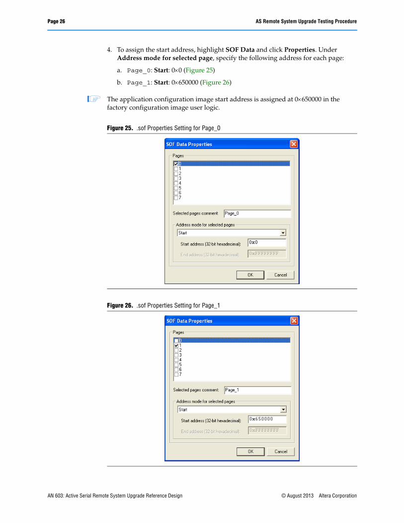
4. To assign the start address, highlight SOF Data and click Properties. Under Address mode for selected page, specify the following address for each page:
a. Page_0: Start: 00 (Figure 25)
b. Page_1: Start: 0650000 (Figure 26)
1 The application configuration image start address is assigned at 0650000 in the factory configuration image user logic.
Figure 25. .sof Properties Setting for Page_0
Figure 26. .sof Properties Setting for Page_1
AN 603: Active Serial Remote System Upgrade Reference Design © August 2013 Altera Corporation
AS Remote System Upgrade Testing Procedure Page 27
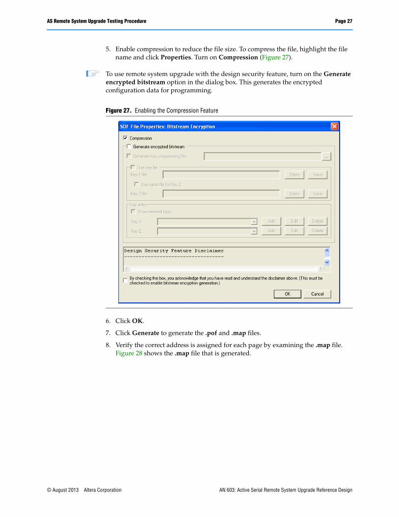
5. Enable compression to reduce the file size. To compress the file, highlight the file name and click Properties. Turn on Compression (Figure 27).
1 To use remote system upgrade with the design security feature, turn on the Generate encrypted bitstream option in the dialog box. This generates the encrypted configuration data for programming.
6. Click OK.
7. Click Generate to generate the .pof and .map files.
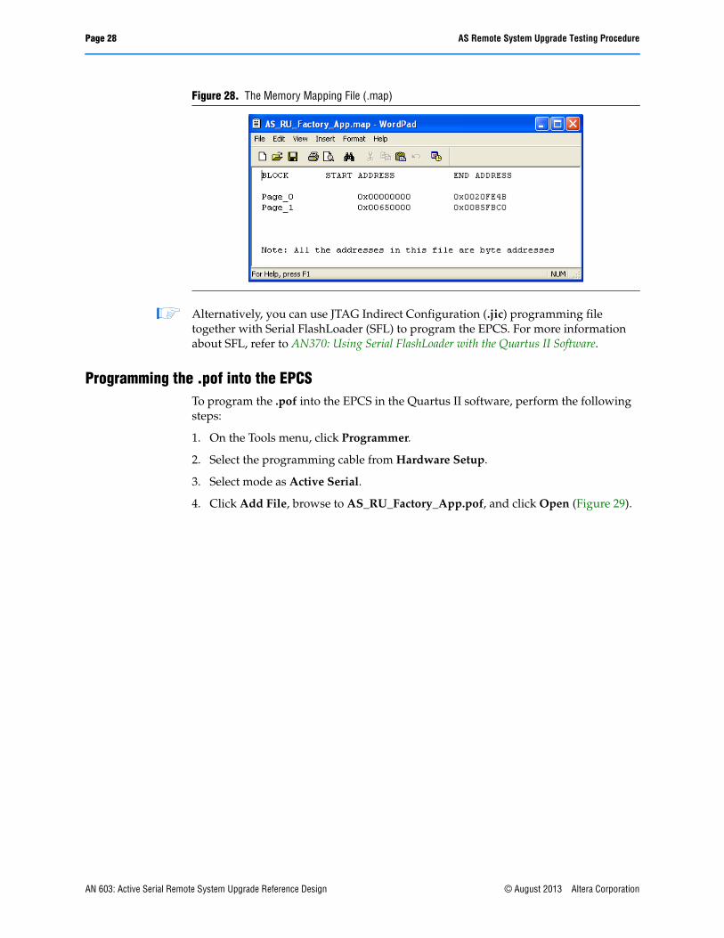
8. Verify the correct address is assigned for each page by examining the .map file. Figure 28 shows the .map file that is generated.
Figure 27. Enabling the Compression Feature
© August 2013 Altera Corporation AN 603: Active Serial Remote System Upgrade Reference Design
Page 28 AS Remote System Upgrade Testing Procedure
1 Alternatively, you can use JTAG Indirect Configuration (.jic) programming file together with Serial FlashLoader (SFL) to program the EPCS. For more information about SFL, refer to AN370: Using Serial FlashLoader with the Quartus II Software.
Programming the .pof into the EPCSTo program the .pof into the EPCS in the Quartus II software, perform the following steps:
1. On the Tools menu, click Programmer.
2. Select the programming cable from Hardware Setup.
3. Select mode as Active Serial.
4. Click Add File, browse to AS_RU_Factory_App.pof, and click Open (Figure 29).
Figure 28. The Memory Mapping File (.map)
AN 603: Active Serial Remote System Upgrade Reference Design © August 2013 Altera Corporation

AS Remote System Upgrade Testing Procedure Page 29
5. Under the Program/Configure column, turn on the check box for Page_0 and Page_1 (Figure 30).
6. Click Start to begin the .pof programming into the EPCS.
Figure 29. Adding .pof into the Quartus II Programmer
Figure 30. Enabling .pof Programming from the Quartus II Programmer
© August 2013 Altera Corporation AN 603: Active Serial Remote System Upgrade Reference Design

Page 30 AS Remote System Upgrade Testing Procedure
Configuring Arria II GX Devices in Remote Update ModeThis section describes the transition of the configuration images in remote update mode for this reference design.
After you have successfully downloaded the .pof into the EPCS, you can power down and power up the board to allow the Arria II GX device to load the factory configuration image for the first time. To begin the reconfiguration of the application configuration image, assert the start_write input pin of the factory configuration image user logic. This triggers Arria II GX device to configure itself with the application configuration image from the specified location. You can return to the factory configuration image by triggering one of the system reconfiguration conditions. Figure 31 shows the transition between the configuration images in remote update mode.
1 For more information about the system reconfiguration trigger condition, refer to the “Remote System Upgrade Reconfiguration” on page 19.
Figure 31. Transition Between Configuration Images in Remote Update Mode
Notes to Figure 31:
(1) ‘1’ indicates LED is turned on. ‘0’ indicates LED is turned off. ‘X’ indicates is blinking.(2) After power up, the LED[2..0] equals to 3’b111. LED[2..0] status varies according to the system reconfiguration trigger condition. For
more information about the system status based on LED[2..0], refer to Table 2 on page 9.(3) This reference design incorporates only one application configuration image. You can trigger the reconfiguration to a new location by setting the
image_update input to logic high before asserting the start_write input on the factory user logic. This triggers the Arria II GX remote update circuitry to load the new image at start address of 0900000.
(4) For more information about the system reconfiguration trigger condition, refer to the “Remote System Upgrade Reconfiguration” on page 19.
Factory Image (Page_0)
LED[2..0] = 111 (1), (2)
Application Image (Page_1)
LED[2..0] = X1X (1)
New Application Image (3)
Error during configuration or user mode operation (4)
Assert start_write input of theapplication user logic
Assert start_write inputof the factory user logic (3)
Power Up
Error during configuration or user mode operation (4)
Assert start_write input of theapplication user logic
Assert start_write input of thefactory user logic (3)
Configuration Error
AN 603: Active Serial Remote System Upgrade Reference Design © August 2013 Altera Corporation

Revision History Page 31
101 Innovation DriveSan Jose, CA 95134www.altera.comTechnical Supportwww.altera.com/support
Copyright © 2013 Altera Corporation. All rights reserved. Altera, The Programmable Solutions Company, the stylized Altera logo, specific device designations, and all other words and logos that are identified as trademarks and/or service marks are, unless noted otherwise, the trademarks and service marks of Altera Corporation in the U.S. and other countries. All other product or service names are the property of their respective holders. Altera products are protected under numerous U.S. and foreign patents and pending applications, maskwork rights, and copyrights. Altera warrants performance of its semiconductor products to current specifications in accordance with Altera's standard warranty, but reserves the right to make changes to any products and services at any time without notice. Altera assumes no responsibility or liability arising out of the application or use of any information, product, or service described herein except as expressly agreed to in writing by Altera Corporation. Altera customers are advised to obtain the latest version of device specifications before relying on any published information and before placing orders for products or services.
Revision HistoryTable 3 lists the revision history for this application note.
Table 3. Document Revision History
Date Version Changes Made
August 2013 1.1 Updated the asmi_addr[23..0] variable in Table 1.
April 2010 1.0 Initial Release.
© August 2013 Altera Corporation AN 603: Active Serial Remote System Upgrade Reference Design