an 170 using the ftdi vinco libraries - ftdi chip home page · 2016-07-25 · an_170 using the ftdi...
TRANSCRIPT

Future Technology Devices International Ltd (FTDI)
Unit 1, 2 Seaward Place, Centurion Business Park, Glasgow G41 1HH, United Kingdom
Tel.: +44 (0) 141 429 2777 Fax: + 44 (0) 141 429 2758
E-Mail (Support): [email protected] Web: http://www.ftdichip.com
Use of FTDI devices in life support and/or safety applications is entirely at the user’s risk, and the user agrees to defend, indemnify and hold harmless FTDI from any and all damages, claims, suits or expense
resulting from such use.
© Copyright 2011 Future Technology Devices International Ltd
Future Technology Devices International Ltd
AN_170 Using the FTDI Vinco_Libraries
Document Reference No.: FT_000408
Version 2.1
Issue Date: 2011-07-20

© Copyright 2011 Future Technology Devices International Ltd 1
Document Reference No.: FT_000408 AN_170 Using the FTDI Vinco_Libraries
Version: Version 2.1 Clearance No.: FTDI# 204
Table of Contents
1 INTRODUCTION ..................................................................................... 7
2 DATA TYPES IN VINCO LIBRARIES ..................................................... 8
3 BEFORE USING THE VINCO LIBRARIES ............................................. 9
3.1 Vinco Application Wizard ................................................................................... 9
3.2 Managing the library list ................................................................................... 11
3.3 main.c and vinco.h ............................................................................................ 11
3.4 Vinco sketch format .......................................................................................... 12
3.4.1 setup() .................................................................................................................................... 12
3.4.2 loop() ...................................................................................................................................... 12
3.4.3 setupInterrupts() .................................................................................................................... 12
4 DIGITAL I/O LIBRARY .......................................................................... 13
4.1 Getting familiar with the APIs ........................................................................... 13
4.1.1 Pin Access APIs .................................................................................................................... 13
4.1.2 Port Access APIs ................................................................................................................... 15
4.2 Using on-board LEDs ........................................................................................ 16
4.3 Example Application: 7-segment Display........................................................ 17
4.3.1 Hardware Setup ..................................................................................................................... 17
4.3.2 Software ................................................................................................................................. 18
5 TIME LIBRARY ..................................................................................... 23
5.1 Getting familiar with the APIs ........................................................................... 23
5.1.1 millis() .................................................................................................................................... 23
5.1.2 micros() .................................................................................................................................. 23
5.1.3 delay() .................................................................................................................................... 23
5.1.4 delayMicroseconds48Mhz() ................................................................................................... 24
5.1.5 delayMicroseconds24Mhz() ................................................................................................... 24
5.1.6 delayMicroseconds12Mhz() ................................................................................................... 25
5.2 The drawback of using delay() and delayMicroseconds() ............................. 25
5.3 Example Application ......................................................................................... 25
5.3.1 Blink with delay ...................................................................................................................... 25
5.3.2 Blink without delay ................................................................................................................. 26
6 SERIAL LIBRARY ................................................................................ 27
6.1 Getting familiar with the APIs ........................................................................... 27
6.1.1 begin() .................................................................................................................................... 27
6.1.2 end() ...................................................................................................................................... 27

© Copyright 2011 Future Technology Devices International Ltd 2
Document Reference No.: FT_000408 AN_170 Using the FTDI Vinco_Libraries
Version: Version 2.1 Clearance No.: FTDI# 204
6.1.3 available() .............................................................................................................................. 27
6.1.4 read() ..................................................................................................................................... 28
6.1.5 write() ..................................................................................................................................... 28
6.1.6 flush() ..................................................................................................................................... 29
6.1.7 print() ..................................................................................................................................... 29
6.1.8 println() ................................................................................................................................... 30
6.1.9 printstr() ................................................................................................................................. 30
6.2 Porting guide ..................................................................................................... 30
6.2.1 Initializing ............................................................................................................................... 31
6.2.2 Porting a sample application ................................................................................................. 31
6.3 Getting the setup ready .................................................................................... 33
7 INTERRUPTS LIBRARY ....................................................................... 34
7.1 Getting familiar with the APIs ........................................................................... 34
7.1.1 interrupts() ............................................................................................................................. 34
7.1.2 noInterrupts() ......................................................................................................................... 34
7.1.3 attachInterrupt() ..................................................................................................................... 34
7.1.4 detachInterrupt() .................................................................................................................... 35
7.2 Interrupt Handling ............................................................................................. 36
7.3 Example Applications ....................................................................................... 36
7.3.1 Auto Generated Interrupt ....................................................................................................... 36
7.3.2 Pushbutton Generated Interrupt ............................................................................................ 38
8 ANALOG I/O LIBRARY ........................................................................ 40
8.1 Getting familiar with the APIs ........................................................................... 40
8.1.1 analogRead() ......................................................................................................................... 40
8.1.2 analogWrite() ......................................................................................................................... 40
8.2 Notes on usage of the Analog I/O Library ....................................................... 41
8.2.1 Reference voltage.................................................................................................................. 41
8.2.2 ADC converter resolution ...................................................................................................... 41
8.2.3 PWM output ........................................................................................................................... 41
8.3 Sample application ............................................................................................ 41
8.3.1 Hardware Setup ..................................................................................................................... 41
8.3.2 Software ................................................................................................................................. 42
9 ETHERNET LIBRARY .......................................................................... 43
9.1 Getting familiar with the APIs ........................................................................... 43
9.1.1 Ethernet core functions .......................................................................................................... 43
9.1.2 Server functions ..................................................................................................................... 45
9.1.3 Client ...................................................................................................................................... 47

© Copyright 2011 Future Technology Devices International Ltd 3
Document Reference No.: FT_000408 AN_170 Using the FTDI Vinco_Libraries
Version: Version 2.1 Clearance No.: FTDI# 204
9.1.4 Udp ........................................................................................................................................ 53
9.2 Porting Guide from Arduino Ethernet Library ................................................. 56
9.2.1 TCP Client ............................................................................................................................. 56
9.2.2 TCP Server ............................................................................................................................ 56
9.3 Sample Applications ......................................................................................... 56
9.3.1 TCP Communication ............................................................................................................. 56
9.3.2 UDP Communication ............................................................................................................. 58
10 USB HOST LIBRARY ........................................................................... 61
10.1 Getting familiar with the APIs ........................................................................... 61
10.1.1 usbhost_init() ......................................................................................................................... 61
10.1.2 open_host_dev() .................................................................................................................... 61
10.1.3 close_host_dev() ................................................................................................................... 61
10.1.4 read() ..................................................................................................................................... 62
10.1.5 write() ..................................................................................................................................... 62
10.1.6 cmdctl() .................................................................................................................................. 62
10.1.7 setup() .................................................................................................................................... 63
10.2 Control Request ................................................................................................. 63
10.2.1 VOS_IOCTL_USBHOST_GET_CONNECT_STATE ............................................................ 63
10.2.2 VOS_IOCTL_USBHOST_ENUMERATE .............................................................................. 63
10.2.3 VOS_IOCTL_USBHOST_GET_USB_STATE ...................................................................... 64
10.2.4 VOS_IOCTL_USBHOST_DEVICE_GET_COUNT ............................................................... 64
10.2.5 VOS_IOCTL_USBHOST_DEVICE_GET_NEXT_HANDLE .................................................. 65
10.2.6 VOS_IOCTL_USBHOST_DEVICE_FIND_HANDLE_BY_VID_PID ..................................... 65
10.2.7 VOS_IOCTL_USBHOST_DEVICE_FIND_HANDLE_BY_CLASS ........................................ 66
10.2.8 VOS_IOCTL_USBHOST_DEVICE_GET_VID_PID .............................................................. 67
10.2.9 VOS_IOCTL_USBHOST_DEVICE_GET_CLASS_INFO...................................................... 67
10.2.10 VOS_IOCTL_USBHOST_DEVICE_GET_DEV_INFO .......................................................... 68
10.2.11 VOS_IOCTL_USBHOST_DEVICE_GET_CONTROL_ENDPOINT_HANDLE ..................... 69
10.2.12 VOS_IOCTL_USBHOST_DEVICE_GET_BULK_IN_ENDPOINT_HANDLE........................ 70
10.2.13 VOS_IOCTL_USBHOST_DEVICE_GET_BULK_OUT_ENDPOINT_HANDLE.................... 70
10.2.14 VOS_IOCTL_USBHOST_DEVICE_GET_INT_IN_ENDPOINT_HANDLE ........................... 71
10.2.15 VOS_IOCTL_USBHOST_DEVICE_GET_INT_OUT_ENDPOINT_HANDLE ....................... 72
10.2.16 VOS_IOCTL_USBHOST_DEVICE_GET_ISO_IN_ENDPOINT_HANDLE ........................... 72
10.2.17 VOS_IOCTL_USBHOST_DEVICE_GET_ISO_OUT_ENDPOINT_HANDLE ....................... 73
10.2.18 VOS_IOCTL_USBHOST_DEVICE_GET_NEXT_ENDPOINT_HANDLE ............................. 74
10.2.19 VOS_IOCTL_USBHOST_DEVICE_GET_ENDPOINT_INFO ............................................... 75
10.2.20 VOS_IOCTL_USBHOST_SET_INTERFACE ....................................................................... 75
10.2.21 VOS_IOCTL_USBHOST_DEVICE_CLEAR_ENDPOINT_HALT ......................................... 76

© Copyright 2011 Future Technology Devices International Ltd 4
Document Reference No.: FT_000408 AN_170 Using the FTDI Vinco_Libraries
Version: Version 2.1 Clearance No.: FTDI# 204
10.2.22 VOS_IOCTL_USBHOST_DEVICE_CLEAR_HOST_HALT .................................................. 77
10.2.23 VOS_IOCTL_USBHOST_DEVICE_SET_HOST_HALT ....................................................... 78
10.2.24 VOS_IOCTL_USBHOST_DEVICE_CLEAR_ENDPOINT_TRANSFER ............................... 79
10.2.25 VOS_IOCTL_USBHOST_HW_GET_FRAME_NUMBER ..................................................... 79
10.2.26 VOS_IOCTL_USBHUB_HUB_PORT_COUNT ..................................................................... 80
10.2.27 VOS_IOCTL_USBHUB_HUB_STATUS ............................................................................... 80
10.2.28 VOS_IOCTL_USBHUB_PORT_STATUS ............................................................................. 81
10.2.29 VOS_IOCTL_USBHUB_CLEAR_C_HUB_LOCAL_POWER ............................................... 81
10.2.30 VOS_IOCTL_USBHUB_CLEAR_C_HUB_OVERCURRENT. .............................................. 82
10.2.31 VOS_IOCTL_USBHUB_CLEAR_PORT_ENABLE ............................................................... 82
10.2.32 VOS_IOCTL_USBHUB_SET_PORT_SUSPEND ................................................................. 83
10.2.33 VOS_IOCTL_USBHUB_CLEAR_PORT_SUSPEND ............................................................ 83
10.2.34 VOS_IOCTL_USBHUB_SET_PORT_RESET ...................................................................... 84
10.2.35 VOS_IOCTL_USBHUB_SET_PORT_POWER ..................................................................... 85
10.2.36 VOS_IOCTL_USBHUB_CLEAR_PORT_POWER ................................................................ 85
10.2.37 VOS_IOCTL_USBHUB_CLEAR_C_PORT_CONNECTION ................................................ 86
10.2.38 VOS_IOCTL_USBHUB_CLEAR_C_PORT_ENABLE .......................................................... 86
10.2.39 VOS_IOCTL_USBHUB_CLEAR_C_PORT_SUSPEND ....................................................... 86
10.2.40 VOS_IOCTL_USBHUB_CLEAR_C_PORT_OVERCURRENT ............................................. 86
10.2.41 VOS_IOCTL_USBHUB_CLEAR_C_PORT_RESET ............................................................. 87
10.3 Data Structures .................................................................................................. 87
10.3.1 usbhost_ioctl_cb_vid_pid_t ................................................................................................... 87
10.3.2 usbhost_ioctl_cb_class_t ....................................................................................................... 87
10.3.3 usbhost_ioctl_cb_dev_info_t ................................................................................................. 88
10.3.4 usbhost_ioctl_cb_ep_info_t ................................................................................................... 88
10.3.5 usbhost_ioctl_cb_t ................................................................................................................. 89
typedef struct _usbhost_ioctl_cb_t ....................................................................................................... 89
11 USB SLAVE LIBRARY ......................................................................... 90
11.1 Getting familiar with the APIs ........................................................................... 90
11.1.1 init() ........................................................................................................................................ 90
11.1.2 getState() ............................................................................................................................... 90
11.1.3 setConfiguration() .................................................................................................................. 90
11.1.4 getConfiguration() .................................................................................................................. 91
11.1.5 setAddress() .......................................................................................................................... 91
11.1.6 setupTransfer() ...................................................................................................................... 92
11.1.7 waitSetupRcvd() .................................................................................................................... 92
11.1.8 initEp() ................................................................................................................................... 92
11.1.9 setEpMaxPcktSize() .............................................................................................................. 93

© Copyright 2011 Future Technology Devices International Ltd 5
Document Reference No.: FT_000408 AN_170 Using the FTDI Vinco_Libraries
Version: Version 2.1 Clearance No.: FTDI# 204
11.1.10 transfer() ................................................................................................................................ 93
11.1.11 disconnect() ........................................................................................................................... 94
11.1.12 stallEp() .................................................................................................................................. 94
11.1.13 clearEp() ................................................................................................................................ 95
11.1.14 epState() ................................................................................................................................ 95
11.1.15 disableInterrupts() .................................................................................................................. 95
11.1.16 enableInterrupts() .................................................................................................................. 96
11.1.17 waitOnUSBSuspend() ........................................................................................................... 96
11.1.18 waitOnUSBResume() ............................................................................................................ 96
11.1.19 issueRemoteWakeup() .......................................................................................................... 97
12 Contact Information............................................................................. 98
Appendix A – Legal Disclaimer: ............................................................. 100
Appendix B – Revision History ............................................................... 101

© Copyright 2011 Future Technology Devices International Ltd 6
Document Reference No.: FT_000408 AN_170 Using the FTDI Vinco_Libraries
Version: Version 2.1 Clearance No.: FTDI# 204
List of Figures and Tables
Figure 1 – Vinco Digital I/O Pins .................................................................................................................. 13
Figure 2 – Hardware Connection Diagram for 7-segment Display ........................................................... 17
Figure 3 – 7-segment Display ....................................................................................................................... 18
Figure 4 – Output of the program as it can be seen on a terminal emulator ........................................... 32
Figure 5 – Hardware setup for serial communications .............................................................................. 33
Figure 6 – Circuit for Analog I/O Demo Application ................................................................................... 42

© Copyright 2011 Future Technology Devices International Ltd 7
Document Reference No.: FT_000408 AN_170 Using the FTDI Vinco_Libraries
Version: Version 2.1 Clearance No.: FTDI# 204
1 INTRODUCTION
The use of the Vinculum-II firmware/drivers revolves around a Real-time Operating System (RTOS). While this approach provides a lot of advantages for systems that are time-critical, it may take time to learn and use the provided utilities effectively. The Arduino APIs, on the other hand, hide most system details from users so that they can learn to use the board in an intuitive way. As a result, the number of people using the Arduino platform is increasing day by day. With that in mind, the Vinco libraries are designed with the same interface as Arduino APIs to provide an easier way for students, hobbyists... to use the Vinco, and to provide Arduino users with a friendly alternative platform for their needs.
This document is intended to help first time users of Vinco. It also can serve a purpose as a reference document on porting and developing application from scratch on FTDI’s rapid prototyping Vinco module. Throughout this document ample examples are provided to familiarize the user with how to use Vinco Software libraries for rapid application development. This document details how to use the digital, analog, serial, timer and interrupt libraries and their APIs. At the end of the document sample applications are provided for reference. Please refer to individual sections of libraries on how to build an application using library specific APIs.
Throughout the application note, reference is made to the Vinco development board. Further information on this Vinculum-II development platform is available from the FTDI website at http://www.ftdichip.com/.
Note: Any sample code provided in this note is for illustration purposes and is not guaranteed or supported by FTDI.

© Copyright 2011 Future Technology Devices International Ltd 8
Document Reference No.: FT_000408 AN_170 Using the FTDI Vinco_Libraries
Version: Version 2.1 Clearance No.: FTDI# 204
2 DATA TYPES IN VINCO LIBRARIES
In some circumstances, there is a need to know the size of the data being used. The following table presents the data types supported by the Vinculum II compiler and their corresponding sizes:
Data Type Size in Bits
(unsigned) char 8
(unsigned) short 16
(unsigned) int 32
(unsigned) long 32
void 0
port 8
Note: There is no support for floating point types.
To generate optimum code the char data type should be used as much as possible. Long and int should only ever be used when 32-bit values are required.
For a better indication of variable size in the code, the following data types have been internally defined. Users will not need to perform any action to use these data types.
Data Type Corresponding Type Size in Bits
uint8 / int8 unsigned char / char 8
uint16 / int16 unsigned short / short 16
uint32 unsigned int / unsigned long 32
int32 int / long 32
© Copyright 2011 Future Technology Devices International Ltd 9
Document Reference No.: FT_000408 AN_170 Using the FTDI Vinco_Libraries
Version: Version 2.1 Clearance No.: FTDI# 204
3 BEFORE USING THE VINCO LIBRARIES
3.1 Vinco Application Wizard
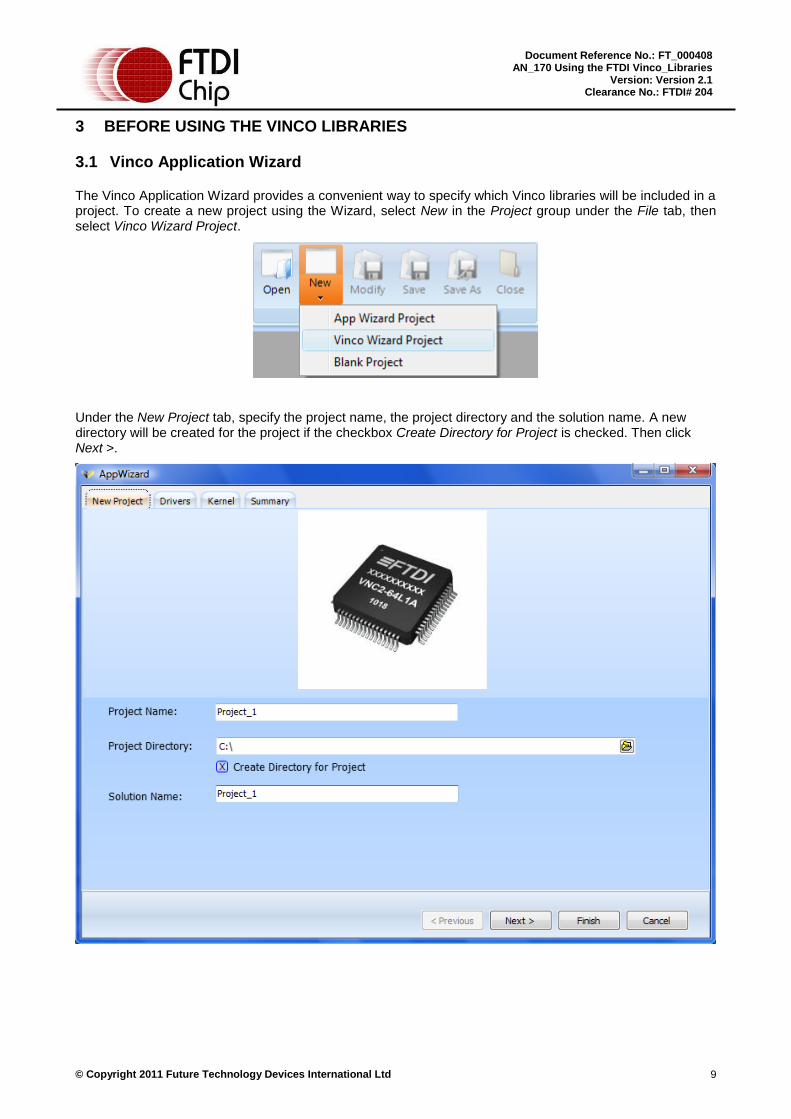
The Vinco Application Wizard provides a convenient way to specify which Vinco libraries will be included in a project. To create a new project using the Wizard, select New in the Project group under the File tab, then select Vinco Wizard Project.
Under the New Project tab, specify the project name, the project directory and the solution name. A new directory will be created for the project if the checkbox Create Directory for Project is checked. Then click Next >.
© Copyright 2011 Future Technology Devices International Ltd 10
Document Reference No.: FT_000408 AN_170 Using the FTDI Vinco_Libraries
Version: Version 2.1 Clearance No.: FTDI# 204
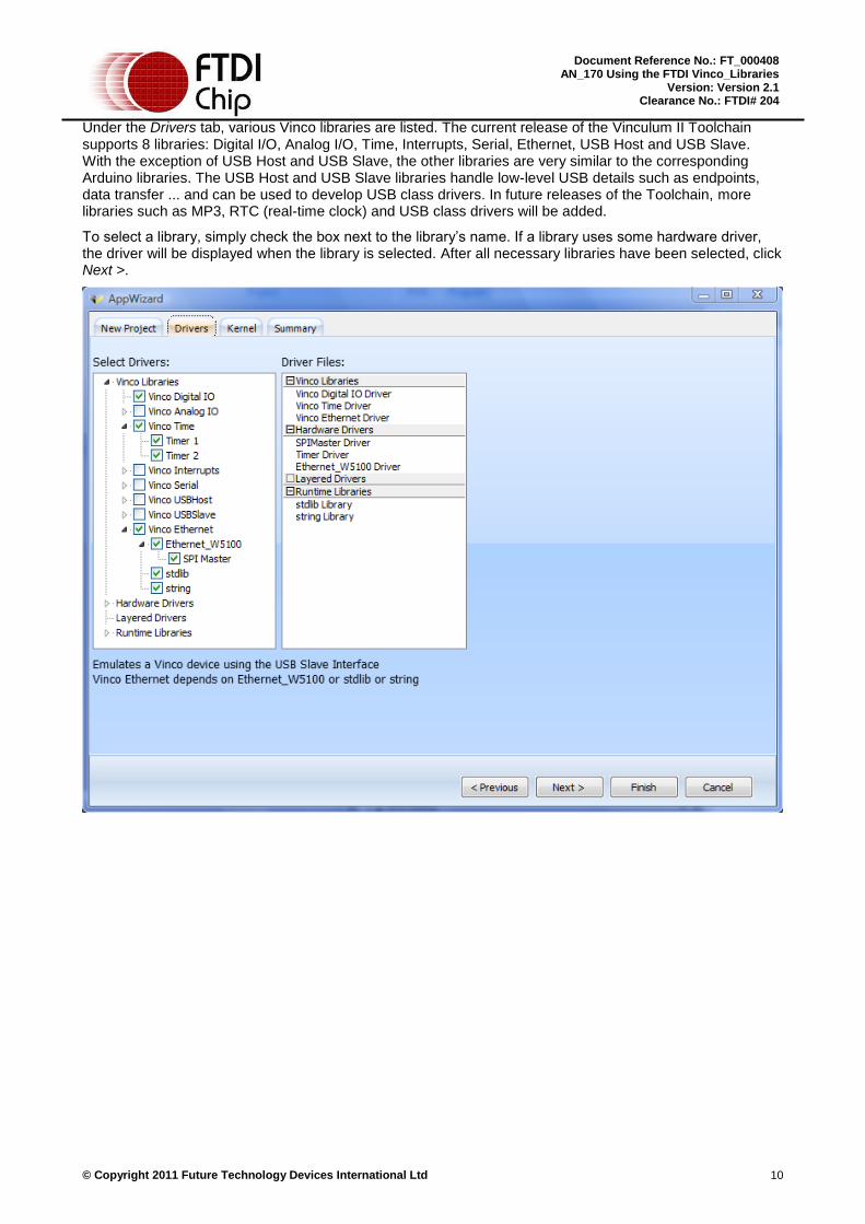
Under the Drivers tab, various Vinco libraries are listed. The current release of the Vinculum II Toolchain supports 8 libraries: Digital I/O, Analog I/O, Time, Interrupts, Serial, Ethernet, USB Host and USB Slave. With the exception of USB Host and USB Slave, the other libraries are very similar to the corresponding Arduino libraries. The USB Host and USB Slave libraries handle low-level USB details such as endpoints, data transfer ... and can be used to develop USB class drivers. In future releases of the Toolchain, more libraries such as MP3, RTC (real-time clock) and USB class drivers will be added.
To select a library, simply check the box next to the library’s name. If a library uses some hardware driver, the driver will be displayed when the library is selected. After all necessary libraries have been selected, click Next >.

© Copyright 2011 Future Technology Devices International Ltd 11
Document Reference No.: FT_000408 AN_170 Using the FTDI Vinco_Libraries
Version: Version 2.1 Clearance No.: FTDI# 204
Under the Kernel tab, some of the parameters need to be specified for the operation of the Vinculum II RTOS. Their default values should be used. Click Next > to view the summary report or Finish to complete the creation of the new project.
3.2 Managing the library list
In order to add or remove some libraries during development, select Modify in the Project group under the File tab.
The Application Wizard will open and libraries can be added to or removed from the project. The existing application code will not be affected.
3.3 main.c and vinco.h
These files are created by the Application Wizard. They handle all the differences between Vinculum II software framework and Arduino software framework and should not be modified. These files can be found in the project folder.
© Copyright 2011 Future Technology Devices International Ltd 12
Document Reference No.: FT_000408 AN_170 Using the FTDI Vinco_Libraries
Version: Version 2.1 Clearance No.: FTDI# 204
3.4 Vinco sketch format
Similar to the Arduino sketch, a Vinco sketch needs two essential functions: setup() and loop(). In addition, due to the difference in the software structure between the Arduino and the Vinco, another function needs to be added for Vinco sketches: setupInterrupts(). The details are as follows.
3.4.1 setup()
The setup() function is called when a sketch starts. It is used to initialize variables, pin modes, start using libraries, etc. The setup function will only run once, after each power-up or reset of the Vinco board.
3.4.2 loop()
After creating a setup() function, which initializes and sets the initial values, the loop() function loops consecutively, allowing the program to change and respond. It is used to actively control the Vinco board.
3.4.3 setupInterrupts()
This function is used to attach user-defined interrupt service routines to the interrupt pins. All attachInterrupts() calls need to be placed in this function. This is the main difference between an Arduino sketch and a Vinco sketch. Minor changes (if any) applied to each library will be presented in the section for that library accordingly.

© Copyright 2011 Future Technology Devices International Ltd 13
Document Reference No.: FT_000408 AN_170 Using the FTDI Vinco_Libraries
Version: Version 2.1 Clearance No.: FTDI# 204
4 DIGITAL I/O LIBRARY
4.1 Getting familiar with the APIs
In this section, we will go through digital library API’s and their usage. Also, we will go through the ways of configuring Pin, properties of pin for specific configuration and pin conventions on Vinco board as defined in software.
4.1.1 Pin Access APIs
A Vinco pin can be specified either by its number (0, 1, 2 …) or its name on the board (J3_1, J3_2 …). The figure below shows the numbers and names of all digital I/O pins.
Figure 1 – Vinco Digital I/O Pins
Note: The Pin Access APIs should not be used with J4_7 (GND) and J4_8 (AREF).
4.1.1.1 pinMode()
Syntax
int8 pinMode(uint8 pin, uint8 mode)
Description
Configures the specified pin to behave either as an input or an output.

© Copyright 2011 Future Technology Devices International Ltd 14
Document Reference No.: FT_000408 AN_170 Using the FTDI Vinco_Libraries
Version: Version 2.1 Clearance No.: FTDI# 204
Parameters
pin: pin number / name (refer to Figure 1 for more details)
mode: INPUT or OUTPUT
Returns
One of the following status codes: INVALID_PIN / INVALID_MODE / SUCCESSFUL
Usage
pinMode(pin, mode);
Example
pinMode(0, OUTPUT); /* set pin 0 as OUTPUT */
pinMode(J4_6, INPUT); /* set pin J4-6, i.e. pin 13, as INPUT */
4.1.1.2 digitalWrite()
Syntax
int8 digitalWrite(uint8 pin, uint8 value)
Description
Writes HIGH (3.3V) or LOW (0V) to the specified pin.
Parameters
pin: pin number / name (refer to Figure 1 for more details)
value: HIGH or LOW
Returns
One of the following status codes: INVALID_PIN / INVALID_VALUE / SUCCESSFUL
Usage
digitalWrite(pin, value);
Example
digitalWrite(0, HIGH); /* write HIGH to pin 0 */
digitalWrite(J4_3, LOW); /* write LOW to pin J4-3 */
4.1.1.3 digitalRead()
Syntax
uint8 digitalRead(uint8 pin)
Description
Reads the value of the specified pin.
Parameters
pin: pin number / name (refer to Figure 1 for more details)
Returns
HIGH or LOW
Usage
digitalRead(pin);
© Copyright 2011 Future Technology Devices International Ltd 15
Document Reference No.: FT_000408 AN_170 Using the FTDI Vinco_Libraries
Version: Version 2.1 Clearance No.: FTDI# 204
Example
digitalRead(0); /* read pin 0 */
4.1.2 Port Access APIs
The Port Access APIs provide convenient access to multiple pins with a single command. There are 4 defined ports on the Vinco board:
Pins from J3-1 to J3-8 are grouped to port J3.
Pins from J4-1 to J4-8 are grouped to port J4.
Note: The Port Access APIs have no effect on J4-8 (AREF) and J4-7 (GND).
Pins from J5-1 to J5-8 are grouped to port J5.
Pins from J6-1 to J6-8 are grouped to port J6.
4.1.2.1 portMode()
Syntax
int8 portMode(uint8 port, uint8 mode)
Description
Sets the specified port as INPUT or OUTPUT.
Parameters
port: port name (J3, J4, J5, J6)
mode: INPUT or OUTPUT
Returns
One of the following status codes: INVALID_PORT / INVALID_MODE / SUCCESSFUL
Usage
portMode(port, mode);
Example
portMode(J3, INPUT); /* set the whole port J3 as INPUT */
4.1.2.2 portWrite()
Syntax
int8 portWrite(uint8 port, uint8 value)
Description
Writes a value to the port specified.
Parameters
port: port name (J3, J4, J5, J6)
value: an 8-bit value corresponding to 8 pins of the port. The leftmost bit of value specifies the value to be written to pin 1 and the rightmost bit of value specifies the value to be written to pin 8 of the port.
Note: For port J4, the two rightmost bits of value will be ignored since they are corresponding to J4_7 (GND) and J4_8 (AREF).

© Copyright 2011 Future Technology Devices International Ltd 16
Document Reference No.: FT_000408 AN_170 Using the FTDI Vinco_Libraries
Version: Version 2.1 Clearance No.: FTDI# 204
Returns
One of the following status codes: INVALID_PORT / SUCCESSFUL
Usage
portWrite(port, value);
Example
portWrite(J3, 0xFF); /* write 1 to every pin of port J3 */
portWrite(J4, 0xF0); /* write 0 to J4-5, J4-6 and 1 to J4-1, J4-2, J4-3, J4-4 */
4.1.2.3 portRead()
Syntax
uint8 portRead(uint8 port)
Description
Reads the port specified.
Parameters
port: port name (J3, J4, J5, J6)
Returns
An 8-bit value corresponding to 8 pins of the port. The leftmost bit is the value read from pin 1. The next leftmost bit is the value read from pin 2, and so on. The rightmost bit is the value read from pin 8 of the port.
Note: For port J4, the two leftmost bits are always 0.
Usage
portRead(port);
Example
portRead(J3); /* read port J3 */
4.2 Using on-board LEDs
The Vinco board provides 2 on-board LEDs for simple debugging. They are located near the two USB connectors (LED1 and LED2 in Figure 1 above). These LEDs are active low, meaning they will turn on when the pins that control them are LOW and turn off when the pins that control them are HIGH.
The function digitalWrite() is designed to work with these two LEDs. By using LED1 and LED2 as the pin name, users can turn on the LEDs by calling
digitalWrite(LED1, LOW);
digitalWrite(LED2, LOW);
and turn off the LEDs by calling
digitalWrite(LED1, HIGH);
digitalWrite(LED2, HIGH);
Note: The two LED pins have to be set to OUTPUT (by calling pinMode() function) before being used.

© Copyright 2011 Future Technology Devices International Ltd 17
Document Reference No.: FT_000408 AN_170 Using the FTDI Vinco_Libraries
Version: Version 2.1 Clearance No.: FTDI# 204
4.3 Example Application: 7-segment Display
This application shows numbers from 0 to 9 and “the dot” on a 7-segment display.
4.3.1 Hardware Setup
This simple application only requires a 7-segment display (common anode or common cathode) and a resistor of about 100 Ω - 400Ω.
The display used in this example has a common anode. The Vinco - Breadboard connection is demonstrated in the figure below.
Figure 2 – Hardware Connection Diagram for 7-segment Display
All 8 pins of port J3 are used to control the 8 segments of the display (including the “dot” segment). The figure is for illustration purpose only. Users will need to consult the datasheet for their specific module and modify the connection accordingly.
© Copyright 2011 Future Technology Devices International Ltd 18
Document Reference No.: FT_000408 AN_170 Using the FTDI Vinco_Libraries
Version: Version 2.1 Clearance No.: FTDI# 204
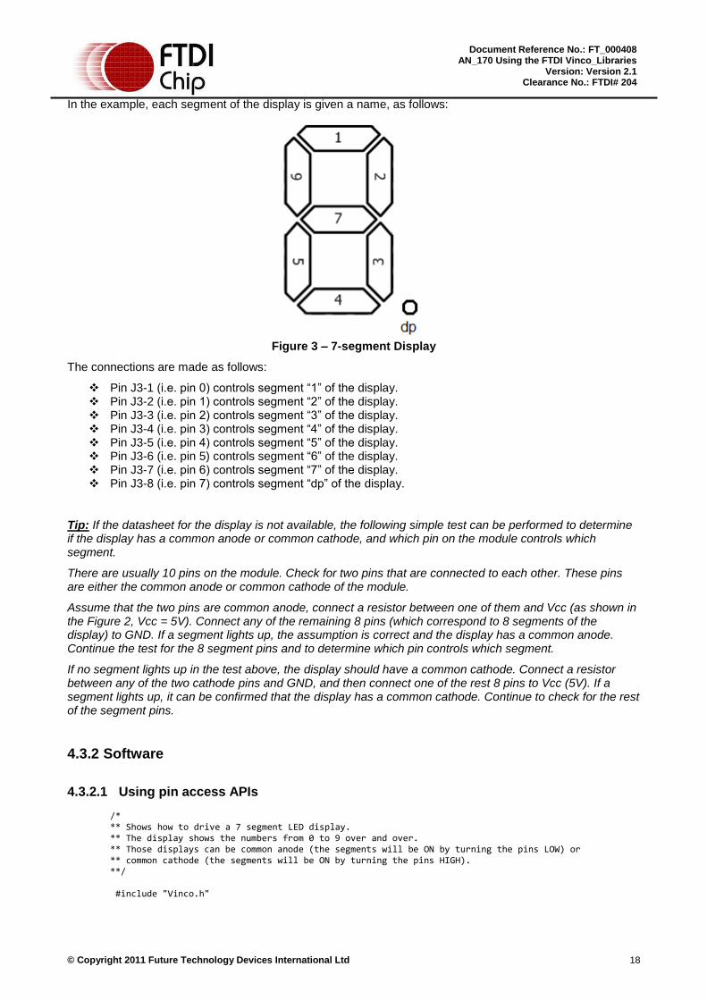
In the example, each segment of the display is given a name, as follows:
Figure 3 – 7-segment Display
The connections are made as follows:
Pin J3-1 (i.e. pin 0) controls segment “1” of the display. Pin J3-2 (i.e. pin 1) controls segment “2” of the display. Pin J3-3 (i.e. pin 2) controls segment “3” of the display. Pin J3-4 (i.e. pin 3) controls segment “4” of the display. Pin J3-5 (i.e. pin 4) controls segment “5” of the display. Pin J3-6 (i.e. pin 5) controls segment “6” of the display. Pin J3-7 (i.e. pin 6) controls segment “7” of the display. Pin J3-8 (i.e. pin 7) controls segment “dp” of the display.
Tip: If the datasheet for the display is not available, the following simple test can be performed to determine if the display has a common anode or common cathode, and which pin on the module controls which segment.
There are usually 10 pins on the module. Check for two pins that are connected to each other. These pins are either the common anode or common cathode of the module.
Assume that the two pins are common anode, connect a resistor between one of them and Vcc (as shown in the Figure 2, Vcc = 5V). Connect any of the remaining 8 pins (which correspond to 8 segments of the display) to GND. If a segment lights up, the assumption is correct and the display has a common anode. Continue the test for the 8 segment pins and to determine which pin controls which segment.
If no segment lights up in the test above, the display should have a common cathode. Connect a resistor between any of the two cathode pins and GND, and then connect one of the rest 8 pins to Vcc (5V). If a segment lights up, it can be confirmed that the display has a common cathode. Continue to check for the rest of the segment pins.
4.3.2 Software
4.3.2.1 Using pin access APIs
/* ** Shows how to drive a 7 segment LED display. ** The display shows the numbers from 0 to 9 over and over. ** Those displays can be common anode (the segments will be ON by turning the pins LOW) or ** common cathode (the segments will be ON by turning the pins HIGH). **/ #include "Vinco.h"

© Copyright 2011 Future Technology Devices International Ltd 19
Document Reference No.: FT_000408 AN_170 Using the FTDI Vinco_Libraries
Version: Version 2.1 Clearance No.: FTDI# 204
/* Define segment map */ /**************************************** ** segment1 ** ----------------- ** | | ** segment6 | |segment2 ** | segment7 | ** ----------------- ** | | ** segment5 | |segment3 ** | | ** ----------------- .segmentDot ** segment4 ****************************************/ /* Define pins which are used to controls segments */ #define segment1 0 #define segment2 1 #define segment3 2 #define segment4 3 #define segment5 4 #define segment6 5 #define segment7 6 #define segmentDot 7 #define dot 10 uint8 number = 0; /* the number to be displayed */ void turn_all_off(void) /* function to turn off all segments */ uint8 i; for (i = 0; i < 8; i++) digitalWrite(i, HIGH); void setup(void) uint8 i; for (i = 0; i < 8; i++) pinMode(i, OUTPUT); /* all segment pins = OUTPUT */ void loop(void) turn_all_off(); /* The LED used in this sample project has a common anode. Therefore, a segment is turned ON when the corresponding pin is pulled LOW */ if (number == 0) /* turn on all segments corresponding to number 0 */ digitalWrite(segment1, LOW); digitalWrite(segment2, LOW); digitalWrite(segment3, LOW); digitalWrite(segment4, LOW); digitalWrite(segment5, LOW); digitalWrite(segment6, LOW); if (number == 1) /* turn on all segments corresponding to number 1 */ digitalWrite(segment2, LOW); digitalWrite(segment3, LOW); if (number == 2) /* turn on all segments corresponding to number 2 */ digitalWrite(segment1, LOW); digitalWrite(segment2, LOW); digitalWrite(segment7, LOW); digitalWrite(segment5, LOW); digitalWrite(segment4, LOW);

© Copyright 2011 Future Technology Devices International Ltd 20
Document Reference No.: FT_000408 AN_170 Using the FTDI Vinco_Libraries
Version: Version 2.1 Clearance No.: FTDI# 204
if (number == 3) /* turn on all segments corresponding to number 3 */ digitalWrite(segment1, LOW); digitalWrite(segment2, LOW); digitalWrite(segment7, LOW); digitalWrite(segment3, LOW); digitalWrite(segment4, LOW); if (number == 4) /* turn on all segments corresponding to number 4 */ digitalWrite(segment6, LOW); digitalWrite(segment7, LOW); digitalWrite(segment2, LOW); digitalWrite(segment3, LOW); if (number == 5) /* turn on all segments corresponding to number 5 */ digitalWrite(segment1, LOW); digitalWrite(segment6, LOW); digitalWrite(segment7, LOW); digitalWrite(segment3, LOW); digitalWrite(segment4, LOW); if (number == 6) /* turn on all segments corresponding to number 6 */ digitalWrite(segment1, LOW); digitalWrite(segment6, LOW); digitalWrite(segment5, LOW); digitalWrite(segment4, LOW); digitalWrite(segment3, LOW); digitalWrite(segment7, LOW); if (number == 7) /* turn on all segments corresponding to number 7 */ digitalWrite(segment1, LOW); digitalWrite(segment2, LOW); digitalWrite(segment3, LOW); if (number == 8) /* turn on all segments corresponding to number 8 */ digitalWrite(segment1, LOW); digitalWrite(segment2, LOW); digitalWrite(segment7, LOW); digitalWrite(segment5, LOW); digitalWrite(segment4, LOW); digitalWrite(segment3, LOW); digitalWrite(segment6, LOW); if (number == 9) /* turn on all segments corresponding to number 9 */ digitalWrite(segment1, LOW); digitalWrite(segment6, LOW); digitalWrite(segment7, LOW); digitalWrite(segment2, LOW); digitalWrite(segment3, LOW); digitalWrite(segment4, LOW); if (number == dot) /* turn on the ‚dot‛ */ digitalWrite(segmentDot, LOW); delay(1000); /* wait for a second */ number++; /* increment the number */ if (number > dot) /* range check, if greater then 'dot' (i.e. 10) go back to 0 */ number = 0;

© Copyright 2011 Future Technology Devices International Ltd 21
Document Reference No.: FT_000408 AN_170 Using the FTDI Vinco_Libraries
Version: Version 2.1 Clearance No.: FTDI# 204
4.3.2.2 Using port access APIs
/* ** Shows how to drive a 7 segment LED display. ** The display shows the numbers from 0 to 9 over and over. ** Those displays can be common anode (the segments will be ON by turning the pins LOW) or ** common cathode (the segments will be ON by turning the pins HIGH). **/
#include "Vinco.h"
/* Define segment map */ /***************************************************** ** segment1 ** ----------------- ** | | ** segment6 | |segment2 ** | segment7 | ** ----------------- ** | | ** segment5 | |segment3 ** | | ** ----------------- .segmentDot ** segment4 *****************************************************/ /* Define output patterns for numbers 0 -> 9 */ /* The LED used in this sample project has a common anode. ** Therefore, a segment is turned ON when the corresponding pin is pulled LOW */ #define patternOff 0xFF /* 11111111 -> all pins are 1, i.e. OFF */ #define pattern0 0x03 /* 00000011 -> pins corresponding to ‚0‛ are 0, i.e. ON */ #define pattern1 0x9F /* 10011111 -> pins corresponding to ‚1‛ are 0, i.e. ON */ #define pattern2 0x25 /* 00100101 -> pins corresponding to ‚2‛ are 0, i.e. ON */ #define pattern3 0x0D /* 00001101 -> pins corresponding to ‚3‛ are 0, i.e. ON */ #define pattern4 0x99 /* 10011001 -> pins corresponding to ‚4‛ are 0, i.e. ON */ #define pattern5 0x49 /* 01001001 -> pins corresponding to ‚5‛ are 0, i.e. ON */ #define pattern6 0x41 /* 01000001 -> pins corresponding to ‚6‛ are 0, i.e. ON */ #define pattern7 0x1F /* 00011111 -> pins corresponding to ‚7‛ are 0, i.e. ON */ #define pattern8 0x01 /* 00000001 -> pins corresponding to ‚8‛ are 0, i.e. ON */ #define pattern9 0x09 /* 00001001 -> pins corresponding to ‚9‛ are 0, i.e. ON */ #define patternDot 0xFE /* 11111110 -> the pin corresponding to ‚dot‛ is 0, i.e. ON */
#define dot 10 uint8 number = 0; /* the number to be displayed */ void setup(void) portMode(J3, OUTPUT); void loop(void) portWrite(J3, patternOff); /* turn off all segments */ if (number == 0) portWrite(J3, pattern0); if (number == 1) portWrite(J3, pattern1); if (number == 2)
portWrite(J3, pattern2); if (number == 3) portWrite(J3, pattern3); if (number == 4)

© Copyright 2011 Future Technology Devices International Ltd 22
Document Reference No.: FT_000408 AN_170 Using the FTDI Vinco_Libraries
Version: Version 2.1 Clearance No.: FTDI# 204
portWrite(J3, pattern4); if (number == 5) portWrite(J3, pattern5); if (number == 6) portWrite(J3, pattern6); if (number == 7) portWrite(J3, pattern7); if (number == 8) portWrite(J3, pattern8); if (number == 9) portWrite(J3, pattern9); if (number == dot) portWrite(J3, patternDot);
delay(1000); /* wait for a second */ number++; /* increment the number */ if (number > dot) /* range check, if greater then 'dot' (i.e. 10) go back to 0 */ number = 0;

© Copyright 2011 Future Technology Devices International Ltd 23
Document Reference No.: FT_000408 AN_170 Using the FTDI Vinco_Libraries
Version: Version 2.1 Clearance No.: FTDI# 204
5 TIME LIBRARY
5.1 Getting familiar with the APIs
5.1.1 millis()
Syntax
uint32 millis(void)
Description
Returns the number of milliseconds since starting an application.
Note: This function overflows (turns back to zero) after approximately 49.72 days.
Parameters
None
Returns
Number of milliseconds since the program started
Usage
millis();
Example
unsigned long timePassed = millis();
5.1.2 micros()
Syntax
uint32 micros(void)
Description
Returns the number of microseconds since starting an application.
Note: This function overflows (turns back to zero) after approximately 1.19 hours.
Parameters
None
Returns
Number of microseconds since the program started
Usage
micros();
Example
unsigned long timePassed = micros();
5.1.3 delay()
Syntax
void delay(uint16 ms)
Description

© Copyright 2011 Future Technology Devices International Ltd 24
Document Reference No.: FT_000408 AN_170 Using the FTDI Vinco_Libraries
Version: Version 2.1 Clearance No.: FTDI# 204
Pauses the program for the amount of time (in milliseconds) specified as parameter.
Parameters
ms: the number of milliseconds to pause
Returns
None
Usage
delay(ms);
Example
delay(1000); /* pause the program for 1 second */
5.1.4 delayMicroseconds48Mhz()
Syntax
void delayMicroseconds48Mhz(uint32 us)
Description
Pauses the program for the amount of time (in microseconds) specified as parameter when the CPU speed is 48Mhz
Parameters
us: the number of microseconds to pause
Returns
None
Usage
delayMicroseconds48Mhz(us);
Example
delayMicroseconds48Mhz(1000); /* pause the program for 1 millisecond */
5.1.5 delayMicroseconds24Mhz()
Syntax
void delayMicroseconds24Mhz(uint32 us)
Description
Pauses the program for the amount of time (in microseconds) specified as parameter when the CPU speed is 24Mhz
Parameters
us: the number of microseconds to pause
Returns
None
Usage
delayMicroseconds24Mhz(us);
Example
delayMicroseconds24Mhz(1000); /* pause the program for 1 millisecond */

© Copyright 2011 Future Technology Devices International Ltd 25
Document Reference No.: FT_000408 AN_170 Using the FTDI Vinco_Libraries
Version: Version 2.1 Clearance No.: FTDI# 204
5.1.6 delayMicroseconds12Mhz()
Syntax
void delayMicroseconds12Mhz(uint32 us)
Description
Pauses the program for the amount of time (in microseconds) specified as parameter when the CPU speed is 12Mhz
Parameters
us: the number of microseconds to pause
Returns
None
Usage
delayMicroseconds12Mhz(us);
Example
delayMicroseconds12Mhz(1000); /* pause the program for 1 millisecond */
5.2 The drawback of using delay() and delayMicroseconds()
When the Vinculum II is processing delay() or delayMicroseconds(), no other operations (such as ALU operations or pin manipulation) except interrupts can take place. Therefore, despite being easy and convenient to use, they should generally be avoided for long durations of delay. The two functions millis() and micros() provide a better approach to timing control. The following code examples show how to blink an LED using both approaches. Without the delay() function, although users will have to poll the CPU frequently, the CPU will be free to perform other tasks while the current task is on hold.
5.3 Example Application
5.3.1 Blink with delay
/* ** Turns on and off a LED connected to a digital ** pin using the delay() function. This means that other code ** cannot run when the delay is being processed by the CPU ** ** Circuit: pin13 -> LED -> resistor (100Ohm) -> GND */ #include "Vinco.h"
uint8 ledPin = 13;
void setup(void)
pinMode(ledPin, OUTPUT);
void loop(void)
digitalWrite(ledPin, HIGH); delay(1000); /* Other operations cannot run during this delay */ digitalWrite(ledPin, LOW); delay(1000); /* Other operations cannot run during this delay */

© Copyright 2011 Future Technology Devices International Ltd 26
Document Reference No.: FT_000408 AN_170 Using the FTDI Vinco_Libraries
Version: Version 2.1 Clearance No.: FTDI# 204
5.3.2 Blink without delay
/* ** Turns on and off a LED connected to a digital ** pin without using the delay() function. This means that other code ** can run when the delay is being processed by the CPU ** ** Circuit: pin13 -> LED -> resistor (100Ohm) -> GND */ #include "Vinco.h" uint8 ledPin = 13; uint8 status = LOW; /* LED status, initially LOW */ unsigned long previousTime; /* timer variable */ int interval = 1000; /* interval for blinking: 1 second */ void setup(void)
pinMode(ledPin, OUTPUT); previousTime = millis(); /* mark the time */
void loop(void)
/* if (current time – previousTime) > 1 second, change the LED status */ if ((millis() - previousTime) > interval) /* change the LED status */ if (status == LOW) status = HIGH; else status = LOW; digitalWrite(ledPin, status);
previousTime = millis(); /* mark the time */
/* other operations can be performed here without waiting for the ‚delay‛ to complete */
© Copyright 2011 Future Technology Devices International Ltd 27
Document Reference No.: FT_000408 AN_170 Using the FTDI Vinco_Libraries
Version: Version 2.1 Clearance No.: FTDI# 204
6 SERIAL LIBRARY
6.1 Getting familiar with the APIs
6.1.1 begin()
Syntax
void begin(long speed)
Description
Initializes the serial port on Vinco. The UART is configured for no flow control, 8 data bits, 1 stop bit and no parity.
Parameters
speed: baud rate for serial communication
Returns
None
Usage
Serial.begin(speed);
Example
Serial.begin(9600);
6.1.2 end()
Syntax
void end(void)
Description
Closes the serial port on Vinco.
Parameters
None
Returns
None
Usage
Serial.end();
Example
Serial.end();
6.1.3 available()
Syntax
int available(void)
Description
Returns the number of bytes read into internal buffer that may be read.
© Copyright 2011 Future Technology Devices International Ltd 28
Document Reference No.: FT_000408 AN_170 Using the FTDI Vinco_Libraries
Version: Version 2.1 Clearance No.: FTDI# 204
Parameters
None
Returns
Number of bytes in the internal buffer
Usage
Serial.available();
Example
int bytesAvailable = Serial.available();
6.1.4 read()
Syntax
int read(void)
Description
Returns a single byte from the internal buffer.
Parameters
None
Returns
Returns a single byte from the internal buffer if data are available in the internal buffer or -1 if no data is available
Usage
Serial.read();
Example
char byte = (char) Serial.read();
6.1.5 write()
Syntax
void write(char *buf, int len)
Description
Transmits binary data through the serial port.
Parameters
buf: pointer to the buffer containing the data
len: length of the data in the buffer that is to be transmitted
Returns
None
Usage
Serial.write(buf, len);
Example
char someData[] = 0xAB, 0xBA, 0xAB, 0xBA, 0xDE, 0xAD, 0xBE, 0xEF;

© Copyright 2011 Future Technology Devices International Ltd 29
Document Reference No.: FT_000408 AN_170 Using the FTDI Vinco_Libraries
Version: Version 2.1 Clearance No.: FTDI# 204
Serial.write(someData, 8);
6.1.6 flush()
Syntax
void flush(void)
Description
Flushes the incoming serial data buffer.
Parameters
None
Returns
None
Usage
Serial.flush();
Example
Serial.flush();
6.1.7 print()
Syntax
void print(int val, eFormat_t format)
Description
Prints data to the serial port as human-readable ASCII text.
Parameters
val: the value that is to be printed
format: format in which the data is to be printed. The enumerated data type eFormat_t takes the following values:
BYTE // e.g. Serial.print(78, BYTE) gives "N"
BIN // e.g. Serial.print(78, BIN) gives "1001110"
OCT // e.g. Serial.print(78, OCT) gives "116”
DEC // e.g. Serial.print(78, DEC) gives "78"
HEX // e.g. Serial.print(78, HEX) gives "4E"
Returns
None
Usage
Serial.print(val, format);
Example
Serial.print(66, DEC);

© Copyright 2011 Future Technology Devices International Ltd 30
Document Reference No.: FT_000408 AN_170 Using the FTDI Vinco_Libraries
Version: Version 2.1 Clearance No.: FTDI# 204
6.1.8 println()
Syntax
void println(int val, eFormat_t format)
Description
Prints data to the serial port as human-readable ASCII text followed by a new line character.
Parameters
val: the value that is to be printed
format: format in which the data is to be printed. The enumerated data type eFormat_t takes the following values:
BYTE // e.g. Serial.print(78, BYTE) gives "N"
BIN // e.g. Serial.print(78, BIN) gives "1001110"
OCT // e.g. Serial.print(78, OCT) gives "116”
DEC // e.g. Serial.print(78, DEC) gives "78"
HEX // e.g. Serial.print(78, HEX) gives "4E"
Returns
None
Usage
Serial.println(val, format);
Example
Serial.println(66, DEC);
6.1.9 printstr()
Syntax
void printstr(char *string)
Description
Prints a string to the serial port.
Parameters
string: pointer to null terminated char array
Returns
None
Usage
Serial.printstr(string);
Example
Serial.printstr(‚Hello World\n\r‛);
6.2 Porting guide
The serial communication APIs described in the previous section are designed to make porting from existing Arduino applications over to the Vinco platform easy. However, the serial communications API for Arduino

© Copyright 2011 Future Technology Devices International Ltd 31
Document Reference No.: FT_000408 AN_170 Using the FTDI Vinco_Libraries
Version: Version 2.1 Clearance No.: FTDI# 204
and Vinco have a few differences and the following points need to be considered when porting an Arduino application:
1) The function pointers grouped together in the data structures need to be initialised before any of the APIs are invoked (See section 4.2.1).
2) The function Serial.begin() must be called before the RTOS’s scheduler is invoked (i.e. it should be called from the Setup() function).
3) All the APIs except for Serial.begin() must be called only after the RTOS’s scheduler is invoked(i.e. from the loop() function or other functions that are called directly or indirectly from the loop() function).
4) Unlike in Arduino’s serial communication library, the function Serial.print() always takes two parameters. The first parameter is a value and the second parameter is the format in which the value should be printed.
5) Printing of string is not supported in Serial.print(), instead a new function is provided, which is Serial.printstr which takes only one parameter i.e. a string pointer.
6) Printing floating point number is not supported.
7) Function Serial.peek() is not supported.
6.2.1 Initializing
The serial communication APIs are implemented as a set of function pointers grouped together as members of a data structure. These function pointers need to be initialised before they can be used to make function calls, and they can be done as shown below in the code snippet:
void setup(void) /* Initializing the Serial Communication APIs */ /* Initializing the serial port */ Serial.begin(9600);
Note: Serial.begin() has to be called before the RTOS’s thread scheduler is started. The RTOS’s thread scheduler is typically started from the main() function using the function call vos_start_scheduler().
6.2.2 Porting a sample application
One of the example applications provided for the Arduino serial communication functions is ASCIITable. This application prints the ASCII table, and their equivalent decimal, octal and hexadecimal values. The application is divided into two parts, i.e. the setup() and loop() functions. The ported setup() function is already described in the above section, and the loop() function is shown below:
int thisByte = 33; /* first visible ASCIIcharacter '!' is number 33 */ void loop(void)
if (thisByte == 33) Serial.printstr("\n\rASCII Table ~ Character Map"); Serial.printstr("\n\rBYTE: "); Serial.print(thisByte,BYTE); Serial.printstr("\tBIN: "); Serial.print(thisByte,BIN); Serial.printstr("\tOCT: "); Serial.print(thisByte,OCT); Serial.printstr("\tDEC: ");
© Copyright 2011 Future Technology Devices International Ltd 32
Document Reference No.: FT_000408 AN_170 Using the FTDI Vinco_Libraries
Version: Version 2.1 Clearance No.: FTDI# 204
Serial.print(thisByte,DEC); Serial.printstr("\tHEX: "); Serial.print(thisByte,HEX); thisByte++; if (thisByte == 126) while(1);
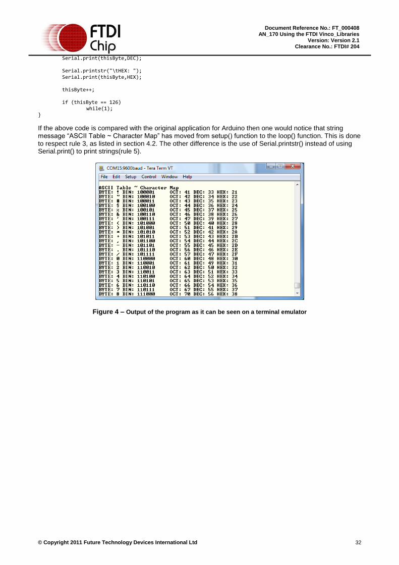
If the above code is compared with the original application for Arduino then one would notice that string message “ASCII Table ~ Character Map” has moved from setup() function to the loop() function. This is done to respect rule 3, as listed in section 4.2. The other difference is the use of Serial.printstr() instead of using Serial.print() to print strings(rule 5).
Figure 4 – Output of the program as it can be seen on a terminal emulator
© Copyright 2011 Future Technology Devices International Ltd 33
Document Reference No.: FT_000408 AN_170 Using the FTDI Vinco_Libraries
Version: Version 2.1 Clearance No.: FTDI# 204
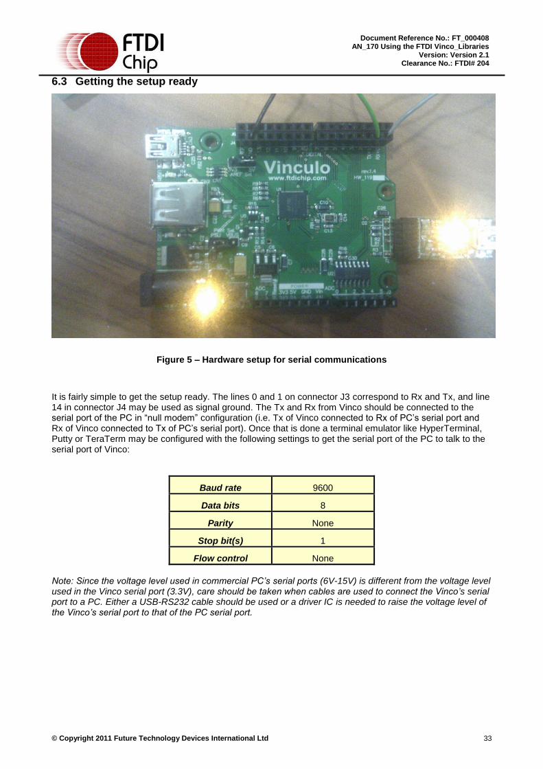
6.3 Getting the setup ready
Figure 5 – Hardware setup for serial communications
It is fairly simple to get the setup ready. The lines 0 and 1 on connector J3 correspond to Rx and Tx, and line 14 in connector J4 may be used as signal ground. The Tx and Rx from Vinco should be connected to the serial port of the PC in “null modem” configuration (i.e. Tx of Vinco connected to Rx of PC’s serial port and Rx of Vinco connected to Tx of PC’s serial port). Once that is done a terminal emulator like HyperTerminal, Putty or TeraTerm may be configured with the following settings to get the serial port of the PC to talk to the serial port of Vinco:
Baud rate 9600
Data bits 8
Parity None
Stop bit(s) 1
Flow control None
Note: Since the voltage level used in commercial PC’s serial ports (6V-15V) is different from the voltage level used in the Vinco serial port (3.3V), care should be taken when cables are used to connect the Vinco’s serial port to a PC. Either a USB-RS232 cable should be used or a driver IC is needed to raise the voltage level of the Vinco’s serial port to that of the PC serial port.

© Copyright 2011 Future Technology Devices International Ltd 34
Document Reference No.: FT_000408 AN_170 Using the FTDI Vinco_Libraries
Version: Version 2.1 Clearance No.: FTDI# 204
7 INTERRUPTS LIBRARY
7.1 Getting familiar with the APIs
7.1.1 interrupts()
Syntax
void interrupts(void)
Description
Re-enables interrupts after being disabled by noInterrupts().
Parameters
None
Returns
None
Usage
interrupts;
Example
interrutps();
7.1.2 noInterrupts()
Syntax
void noInterrupts(void)
Description
Disables the interrupts.
Parameters
None
Returns
None
Usage
noInterrupts;
Example
noInterrutps();
7.1.3 attachInterrupt()
Syntax
int attachInterrupt(uint8 intNum, fncptr isr, uint8 mode)
Description
Allows a specified function to be invoked once an external interrupt occurs.
Parameters
© Copyright 2011 Future Technology Devices International Ltd 35
Document Reference No.: FT_000408 AN_170 Using the FTDI Vinco_Libraries
Version: Version 2.1 Clearance No.: FTDI# 204
intNum: Interrupt number which is 0, 1, 2, or 3. The interrupt pins are fixed.
0 – pin 4
1 – pin 5
2 – pin 2
3 – pin 3
isr: Function to be invoked when an interrupt occurs. The function should return void and have no parameters, i.e. void isr(void)
mode: Defines the trigger on when the interrupt will occur. The following are the possible values:
LOW – triggers the interrupt whenever the pin is low
CHANGE – triggers the interrupt whenever the pin changes value
RISING – triggers the interrupt when the pin changes from low to high
FALLING – triggers the interrupt when the pin changes from high to low
Returns
One of the status codes: INVALID_INT_NUM / INVALID_MODE / SUCCESSFUL
Usage
attachInterrupt(intNum, isr, mode);
Example
void isr_1(void)
// do something
void setup()
attachinterrupt(0, isr_1, RISING);
7.1.4 detachInterrupt()
Syntax
int detachInterrupt(uint8 intNum)
Description
Removes the interrupt routine attached to a specified interrupt pin.
Parameters
intNum: Interrupt number which is 0-3.
Returns
One of the status codes: INVALID_PIN / SUCCESSFUL
Usage
detachInterrupt(intNum);
Example

© Copyright 2011 Future Technology Devices International Ltd 36
Document Reference No.: FT_000408 AN_170 Using the FTDI Vinco_Libraries
Version: Version 2.1 Clearance No.: FTDI# 204
detachInterrutp(0);
7.2 Interrupt Handling
There are 4 interrupts available for the user. Each interrupt is mapped to a fixed pin. The previous attached Interrupt Service Routine (ISR) will be replaced with the new one if ever the user will configure the same interrupt number.
The user has the option to enable or disable the interrupts. Interrupts are enabled by default, so in the setup() function, there is no need to call interrupts() unless noInterrupts() is called beforehand.
The ISR is competing for time with the main program. Ideally it should be as short a routine as possible. It is used for notification, manipulating counter values or state of variables, etc. It’s not a good idea to have a while or for loop statement or even delay() inside the ISR function.
7.3 Example Applications
7.3.1 Auto Generated Interrupt
/*
* This application will blink the corresponding LED if interrupt occurs on
* pin 4 (interrupt 0) and 5 (interrupt 1) respectively. Interrupts are auto-generated from pin 6 and 7
* respectively.
*
* Libraries used: Interrupts, Digital I/O, Timer
* Pin Configurations: 0,2,6 and 7 - Digital Output
* 4 and 5 - Interrupt pins
* Circuit: Pin 0 is connected to an LED (interrupt indicator for pin4)
* Pin 2 is connected to an LED (interrupt indicator for pin5)
* Pin 6 is the source of interrupt trigger for pin 4
* Pin 7 is the source of interrupt trigger for pin 5
*/
#include "digital_IO.h"
#include "interrupts.h"
#include "time.h"
void blink_0();
void blink_1();
volatile uint8 state_0 = LOW;
volatile uint8 state_1 = LOW;
void setup()
/* LEDs */
© Copyright 2011 Future Technology Devices International Ltd 37
Document Reference No.: FT_000408 AN_170 Using the FTDI Vinco_Libraries
Version: Version 2.1 Clearance No.: FTDI# 204
pinMode(0, OUTPUT); /* output indicator of pin 4 interrupt */
pinMode(2, OUTPUT); /* output indicator of pin 5 interrupt */
/* Interrupt triggers */
pinMode(6, OUTPUT);
pinMode(7, OUTPUT);
/* initialize all outputs to LOW */
digitalWrite(0, LOW);
digitalWrite(2, LOW);
digitalWrite(6, LOW);
digitalWrite(7, LOW);
/* Interrupts trigger by RISING mode */
attachInterrupt(0, blink_0, RISING);
attachInterrupt(1, blink_1, RISING);
void loop()
/* Trigger for pin 4 */
digitalWrite(6, LOW);
digitalWrite(6, HIGH);
/* Trigger for pin 5 */
digitalWrite(7, LOW);
digitalWrite(7, HIGH);
delay(1000);
/* Interrupt 0 routine */
void blink_0()
state_0 = !state_0;
digitalWrite(0, state_0);
/* Interrupt 1 routine */
void blink_1()
state_1 = !state_1;
digitalWrite(2, state_1);

© Copyright 2011 Future Technology Devices International Ltd 38
Document Reference No.: FT_000408 AN_170 Using the FTDI Vinco_Libraries
Version: Version 2.1 Clearance No.: FTDI# 204
7.3.2 Pushbutton Generated Interrupt
/*
* This application will blink the corresponding LED if interrupt occurs on
* pin 4 (interrupt 0) and 5 (interrupt 1) respectively. Triggers come from the pushbuttons.
*
* Libraries used: Interrupts, Digital I/O, Timer
* Pin Configurations: 0 and 2 - Digital Output
* 4 and 5 - Interrupt pins
* Circuit: Pin 0 is connected to an LED (interrupt indicator for pin4)
* Pin 2 is connected to an LED (interrupt indicator for pin5)
* Pin 4 is connected to a pushbutton. When pressed, sends a value
* of HIGH to pin 0.
* Pin 5 is connected to a pushbutton. When pressed, sends a value
* of HIGH to pin 2.
*/
#include "digital_IO.h"
#include "interrupts.h"
#include "time.h"
void blink_0();
void blink_1();
volatile uint8 state_0 = LOW;
volatile uint8 state_1 = LOW;
void setup()
/* LEDs */
pinMode(0, OUTPUT); /* output indicator of pin 4 interrupt */
pinMode(2, OUTPUT); /* output indicator of pin 5 interrupt */
/* initialize all outputs to LOW */
digitalWrite(0, LOW);
digitalWrite(2, LOW);
/* Interrupts trigger by FALLING mode */
attachInterrupt(0, blink_0, FALLING);
attachInterrupt(1, blink_1, FALLING);
void loop()

© Copyright 2011 Future Technology Devices International Ltd 39
Document Reference No.: FT_000408 AN_170 Using the FTDI Vinco_Libraries
Version: Version 2.1 Clearance No.: FTDI# 204
void blink_0()
state_0 = !state_0;
digitalWrite(0, state_0);
void blink_1()
state_1 = !state_1;
digitalWrite(2, state_1);

© Copyright 2011 Future Technology Devices International Ltd 40
Document Reference No.: FT_000408 AN_170 Using the FTDI Vinco_Libraries
Version: Version 2.1 Clearance No.: FTDI# 204
8 ANALOG I/O LIBRARY
8.1 Getting familiar with the APIs
8.1.1 analogRead()
Syntax
uint16 analogRead(uint8 pin)
Description
Reads the value from the specified analog pin.
Parameters
pin: pin number to read from (either A0, A1, A2, A3, A4, A5, A6 or A7) .
Returns
An integer value between 0 to 1023
Usage
analogRead(pin);
Example
analogRead(A0); /* read pin A0 */
8.1.2 analogWrite()
Syntax
void analogWrite(uint8 pin, uint8 value)
Description
Writes an analog value (PWM wave) to a pin.
Parameters
pin: pin number to write to.
Note: The Arduino supports PWM output on digital pins 3, 5, 6, 9, 10, 11. Although it is possible to use any digital pins or analog pins for PWM output on the Vinco board (up to 8 pins), only digital pins 4, 5, 6, 9, 10, 11, 12, 13 are currently supported to make the Vinco board compatible with current Arduino shields.
value: an integer value between 0 and 255
Returns
None
Usage
analogWrite(pin, value);
Example
analogWrite(9, 127); /* PWM signal with 50% duty cycle on pin 9 */
© Copyright 2011 Future Technology Devices International Ltd 41
Document Reference No.: FT_000408 AN_170 Using the FTDI Vinco_Libraries
Version: Version 2.1 Clearance No.: FTDI# 204
8.2 Notes on usage of the Analog I/O Library
8.2.1 Reference voltage
The reference voltage of the analog-to-digital converter (ADC) MCP3008 is determined by the voltage coming into the AREF pin (J4-8). The on-board jumper JP2 can provide a reference voltage of 3.3V or 5V. Any other reference voltage between 2.7V and 5V can be applied to AREF if needed.
8.2.2 ADC converter resolution
The MCP3008 is an 8-channel, 10-bit ADC. For a reference voltage of 5V, input voltages between 0 and 5V will be mapped to integer values between 0 and 1023. This yields a resolution of 5V / 1024 units or 4.9 mV per unit. By changing the reference voltage (coming into AREF), the resolution will be changed accordingly.
8.2.3 PWM output
PWM signal can be used to vary the brightness of a LED or drive a motor at various speeds. After a call to analogWrite(), the pin will generate a steady square wave of the specified duty cycle until the next call to analogWrite() on the same pin. The frequency of the PWM signal is 250 kHz.
There is no need to call pinMode() to set the pin as output before using analogWrite().
8.3 Sample application
In the following application, a potentiometer is used to change the voltage input to an analog input pin. The application then divides the input value by four (in order to convert a number in the range of 0…1023 to a number in the range of 0…255) and writes it to an analog output pin (i.e. a PWM pin). This output pin is connected to a LED to observe the change it is brightness according to the input voltage.
8.3.1 Hardware Setup
The middle pin of the potentiometer is connected to an analog input pin. The other two pins are connected to the supply voltage and GND (which particular pin is connected to supply voltage / GND is not important)
The anode of the LED is connected to an analog output pin. The cathode of the LED is connected to GND through a 100 Ohm resistor.
In this example, A0 is used as the analog input pin and pin 9 (J4-2) is used as the analog ouput pin. The circuit is demonstrated in the figure below.

© Copyright 2011 Future Technology Devices International Ltd 42
Document Reference No.: FT_000408 AN_170 Using the FTDI Vinco_Libraries
Version: Version 2.1 Clearance No.: FTDI# 204
Figure 6 – Circuit for Analog I/O Demo Application
8.3.2 Software
#include "Vinco.h"
void setup(void)
void loop(void)
unsigned short analogInVal;
analogInVal = analogRead(A0); /* A0 is the analog input pin */
analogWrite(9, analogInVal/4); /* Pin 9 is the analog output pin */
delay(10);

© Copyright 2011 Future Technology Devices International Ltd 43
Document Reference No.: FT_000408 AN_170 Using the FTDI Vinco_Libraries
Version: Version 2.1 Clearance No.: FTDI# 204
9 ETHERNET LIBRARY
This library allows a Vinco board to connect to the internet via a Vinco Ethernet shield. The library is composed of three components, namely:
Server: This component contains APIs that make the Vinco board act as a TCP server accepting incoming connections.
Client: This component contains APIs that make the Vinco act as a TCP client that makes outgoing connections.
UDP: This component allows the Vinco to communicate using the UDP protocol.
By specifying #define ETHERNET_H in configuration.h, all three components will be included and users can start using the APIs immediately.
9.1 Getting familiar with the APIs
9.1.1 Ethernet core functions
9.1.1.1 beginMacIp()
Syntax
void beginMacIp(uint8 *mac, uint8 *ip)
Description
Initializes the Ethernet chip (W5100) on the Ethernet shield given the MAC address and IP address. The subnet mask is set to 255.255.255.0 while the gateway is set to the value of the IP address with the last octet set to 1.
Parameters
mac: The MAC address to be assigned to the Ethernet chip which is an array of 6 bytes.
ip: The IP address to be assigned to the Ethernet chip which is an array of 4 bytes.
Returns
None
Usage
Ethernet.beginMacIp(mac, ip);
Example
uint8 mac_addr[] = 0x90,0xA2,0xDA,0x00,0x14,0xBA ;
uint8 ip_addr[] = 192,168,0,150 ;
Ethernet.beginMacIp(mac_addr, ip_addr);
9.1.1.2 beginMacIpGw()
Syntax
void beginMacIpGw(uint8 *mac, uint8 *ip, uint8 *gateway)
Description
Initializes the Ethernet chip (W5100) on the Ethernet shield given the MAC address, IP address and Gateway. The subnet mask is set to 255.255.255.0.
© Copyright 2011 Future Technology Devices International Ltd 44
Document Reference No.: FT_000408 AN_170 Using the FTDI Vinco_Libraries
Version: Version 2.1 Clearance No.: FTDI# 204
Parameters
mac: The MAC address to be assigned to the Ethernet chip which is an array of 6 bytes.
ip: The IP address to be assigned to the Ethernet chip which is an array of 4 bytes.
gateway: The Gateway to be assigned to the Ethernet chip which is an array of 4 bytes.
Returns
None
Usage
Ethernet.beginMacIpGw(mac, ip, gateway);
Example
uint8 mac_addr[] = 0x90,0xA2,0xDA,0x00,0x14,0xBA ;
uint8 ip_addr[] = 192,168,0,150 ;
uint8 gtw_addr[] = 192,168,0,1 ;
Ethernet.beginMacIpGw(mac_addr, ip_addr, gtw_addr);
9.1.1.3 beginMacIpGwSn()
Syntax
void beginMacIpGwSn(uint8 *mac, uint8 *ip, uint8 *gateway, uint8 *subnet)
Description
Initializes the Ethernet chip (W5100) on the Ethernet shield given the MAC address, IP address, Gateway end Subnet Mask.
Parameters
mac: The MAC address to be assigned to the Ethernet chip which is an array of 6 bytes.
ip: The IP address to be assigned to the Ethernet chip which is an array of 4 bytes.
gateway: The Gateway to be assigned to the Ethernet chip which is an array of 4 bytes.
subnet: The Subnet Mask to be assigned to the Ethernet chip which is an array of 4 bytes.
Returns
None
Usage
Ethernet.beginMacIpGwSn(mac, ip, gateway, subnet);
Example
uint8 mac_addr[] = 0x90,0xA2,0xDA,0x00,0x14,0xBA ;
uint8 ip_addr[] = 192,168,0,150 ;
uint8 gtw_addr[] = 192,168,0,1 ;
uint8 subnet_mask [] = 255,255,255,0 ;
Ethernet.beginMacIpGw(mac_addr, ip_addr, gtw_addr, subnet_mask);

© Copyright 2011 Future Technology Devices International Ltd 45
Document Reference No.: FT_000408 AN_170 Using the FTDI Vinco_Libraries
Version: Version 2.1 Clearance No.: FTDI# 204
9.1.2 Server functions
9.1.2.1 begin()
Syntax
void begin(uint16 sPort)
Description
Create a socket for the server and listen for incoming connections.
Parameters
sPort: The server’s port to listen to
Returns
None
Usage
Server.begin(sPort);
Example
Server.begin(80); /* listen to port 80 for incoming connection */
9.1.2.2 available()
Syntax
uint8 available(uint16 sPort, clientInfo *ret)
Description
Gets a client which is connected to the server and has data available for reading.
Parameters
sport: The server’s port to check for
ret: The connected client
Returns
TRUE if there is a client which is connected to the server and has data available for reading.
FALSE otherwise.
Usage
Server.available(sPort, ret);
Example
clientInfo client1;
if (Server.available(80, &client1))
// Read incoming data from client1
© Copyright 2011 Future Technology Devices International Ltd 46
Document Reference No.: FT_000408 AN_170 Using the FTDI Vinco_Libraries
Version: Version 2.1 Clearance No.: FTDI# 204
9.1.2.3 writeBuf()
Syntax
void writeBuf(const uint8 *buf, uint32 size, uint16 sPort)
Description
Writes data to all connected clients.
Parameters
b: The data to write
size: Size (in bytes) of the data to write
sPort: The server’s port to write to
Returns
None
Usage
Server.writeBuf(data, size, sPort);
Example
const uint8 data[] = ‘H’, ’e’, ’l’, ’l’, ’o’ ;
Server.writeBuf(data, 5, 80);
9.1.2.4 writeStr()
Syntax
void writeStr(const char *str, uint16 sPort)
Description
Writes a string to all connected clients.
Parameters
str: The string to write
sPort: The server’s port to write to
Returns
None
Usage
Server.writeStr(str, sPort);
Example
Server.writeStr(‚Hello World!\n\r‛, 80);
9.1.2.5 writeByte()
Syntax
void writeByte(uint8 b, uint16 sPort)
Description
Writes a byte to all connected clients.

© Copyright 2011 Future Technology Devices International Ltd 47
Document Reference No.: FT_000408 AN_170 Using the FTDI Vinco_Libraries
Version: Version 2.1 Clearance No.: FTDI# 204
Parameters
b: The value to write
sPort: The server’s port to write to
Returns
None
Usage
Server.writeByte(b, sPort);
Example
Server.writeByte(‘H’, 80);
9.1.3 Client
9.1.3.1 clientIp()
Syntax
int8 clientIp(clientInfo *info, uint8 *ip, uint16 sPort)
Description
Creates a client which can connect to the specified IP address and port.
Parameters
info: Client information. This structure represents the created client in other function calls.
ip: The server’s IP address to connect to
sPort: The server’s port to connect to
Returns
Upon success, the function will return ETHERNET_LIB_SUCCESS. It will return ETHERNET_LIB_FAILURE otherwise.
Usage
Client.clientIp(info, ip, sPort);
Example
clientInfo client1;
uint8 server_ip[] = 192,168,0,170 ;
uint8 server_port = 80;
Client.clientIp(client1, server_ip, server_port);
9.1.3.2 connect()
Syntax
int8 connect(clientInfo *info)
Description
Connects to the server based on the IP address and port in the client information.
Parameters

© Copyright 2011 Future Technology Devices International Ltd 48
Document Reference No.: FT_000408 AN_170 Using the FTDI Vinco_Libraries
Version: Version 2.1 Clearance No.: FTDI# 204
info: Client information, which is initialized by clientIp().
Returns
Upon success, the function will return ETHERNET_LIB_SUCCESS. It will return ETHERNET_LIB_FAILURE otherwise.
Usage
Client.connect(info);
Example
clientInfo client1;
uint8 server_ip[] = 192,168,0,170 ;
uint8 server_port = 80;
Client.clientIp(client1, server_ip, server_port);
Client.connect(client1);
9.1.3.3 connected()
Syntax
int8 connected(clientInfo *info)
Description
Checks whether the client is connected or not. Note that a client is considered connected if the connection has been closed but there is still unread data.
Parameters
info: Client information, which is initialized by clientIp().
Returns
Upon success, the function will return ETHERNET_LIB_SUCCESS. It will return ETHERNET_LIB_FAILURE otherwise.
Usage
Client.connected(info);
Example
clientInfo client1;
uint8 server_ip[] = 192,168,0,170 ;
uint8 server_port = 80;
Client.clientIp(client1, server_ip, server_port);
Client.connect(client1);
if (Client.connected(client1))
// Send data to server

© Copyright 2011 Future Technology Devices International Ltd 49
Document Reference No.: FT_000408 AN_170 Using the FTDI Vinco_Libraries
Version: Version 2.1 Clearance No.: FTDI# 204
9.1.3.4 writeBuf ()
Syntax
void writeBuf(clientInfo *info, const uint8* data, uint32 len)
Description
Writes data to the server to which the client is connected
Parameters
info: Client information, which is initialized by clientIp()
data: The data to be sent
len: The size of the data to be sent
Returns
None
Usage
Client.writeBuf(info, data, len);
Example
clientInfo client1;
uint8 server_ip[] = 192,168,0,170 ;
uint8 server_port = 80;
uint8 data[] = ‘H’, ‘e’, ‘l’, ‘l’, ‘o’ ;
Client.clientIp(client1, server_ip, server_port);
Client.connect(client1);
if (Client.connected(client1))
Client.writeBuf(client1, data, 5);
9.1.3.5 writeStr()
Syntax
void writeStr(clientInfo *info, const char* data)
Description
Writes a string to the server to which the client is connected
Parameters
info: Client information, which is initialized by clientIp()
data: The string to be sent
Returns
None
Usage
Client.writeStr(info, data);
Example
© Copyright 2011 Future Technology Devices International Ltd 50
Document Reference No.: FT_000408 AN_170 Using the FTDI Vinco_Libraries
Version: Version 2.1 Clearance No.: FTDI# 204
clientInfo client1;
uint8 server_ip[] = 192,168,0,170 ;
uint8 server_port = 80;
Client.clientIp(client1, server_ip, server_port);
Client.connect(client1);
if (Client.connected(client1))
Client.writeStr(client1, ‚Hello World!\n\r‛);
9.1.3.6 writeByte()
Syntax
void writeByte(clientInfo *info, uint8 data)
Description
Writes a byte to the server to which the client is connected
Parameters
info: Client information, which is initialized by clientIp()
data: The byte to be sent
Returns
None
Usage
Client.writeByte(info, data);
Example
clientInfo client1;
uint8 server_ip[] = 192,168,0,170 ;
uint8 server_port = 80;
Client.clientIp(client1, server_ip, server_port);
Client.connect(client1);
if (Client.connected(client1))
Client.writeByte(client1, ‘H’);
9.1.3.7 available()
Syntax
uint8 available(clientInfo *info)
Description
Returns the number of bytes available for reading

© Copyright 2011 Future Technology Devices International Ltd 51
Document Reference No.: FT_000408 AN_170 Using the FTDI Vinco_Libraries
Version: Version 2.1 Clearance No.: FTDI# 204
Parameters
info: Client information, which is initialized by clientIp()
Returns
The number of bytes available
Usage
Client.available(info);
Example
clientInfo client1;
uint8 server_ip[] = 192,168,0,170 ;
uint8 server_port = 80;
uint8 bytes_rcvd;
Client.clientIp(client1, server_ip, server_port);
Client.connect(client1);
if (Client.connected(client1))
bytes_rcvd = Client.available(client1);
9.1.3.8 read()
Syntax
int8 read(clientInfo *info)
Description
Read the next byte received from the server
Parameters
info: Client information, which is initialized by clientIp()
Returns
The byte received from the server
Usage
Client.read(info);
Example
clientInfo client1;
uint8 server_ip[] = 192,168,0,170 ;
uint8 server_port = 80;
uint8 bytes_rcvd;
int bytes_read;
Client.clientIp(client1, server_ip, server_port);
Client.connect(client1);
if (Client.connected(client1))

© Copyright 2011 Future Technology Devices International Ltd 52
Document Reference No.: FT_000408 AN_170 Using the FTDI Vinco_Libraries
Version: Version 2.1 Clearance No.: FTDI# 204
bytes_rcvd = Client.available(client1);
for (bytes_read = 0; bytes_read < bytes_rcvd; bytes_read++)
Client.read(client1);
9.1.3.9 flush()
Syntax
void flush(clientInfo *info)
Description
Discards any unread byte that have been written to the client
Parameters
info: Client information, which is initialized by clientIp()
Returns
None
Usage
Client.flush(info);
Example
clientInfo client1;
uint8 server_ip[] = 192,168,0,170 ;
uint8 server_port = 80;
uint8 bytes_rcvd;
int bytes_read;
Client.clientIp(client1, server_ip, server_port);
Client.connect(client1);
if (Client.connected(client1))
bytes_rcvd = Client.available(client1);
for (bytes_read = 0; bytes_read < bytes_rcvd; bytes_read++)
Client.read(client1);
Client.flush(client1); // discard unread bytes, if any

© Copyright 2011 Future Technology Devices International Ltd 53
Document Reference No.: FT_000408 AN_170 Using the FTDI Vinco_Libraries
Version: Version 2.1 Clearance No.: FTDI# 204
9.1.3.10 stop()
Syntax
void stop(clientInfo *info)
Description
Disconnect the client from the server
Parameters
info: Client information, which is initialized by clientIp()
Returns
None
Usage
Client.stop(info);
Example
clientInfo client1;
uint8 server_ip[] = 192,168,0,170 ;
uint8 server_port = 80;
uint8 bytes_rcvd;
int bytes_read;
Client.clientIp(client1, server_ip, server_port);
Client.connect(client1);
if (Client.connected(client1))
bytes_rcvd = Client.available(client1);
for (bytes_read = 0; bytes_read < bytes_rcvd; bytes_read++)
Client.read(client1);
Client.flush(client1); // discard unread bytes, if any
Client.stop(client1);
9.1.4 Udp
9.1.4.1 begin()
Syntax
void begin(uint16 sPort);
Description
Starts listening on the specified port.

© Copyright 2011 Future Technology Devices International Ltd 54
Document Reference No.: FT_000408 AN_170 Using the FTDI Vinco_Libraries
Version: Version 2.1 Clearance No.: FTDI# 204
Parameters
sPort: Port where to listen
Returns
None
Usage
Udp.begin(sPort);
Example
Udp.begin(1357);
9.1.4.2 send()
Syntax
void send(uint8 * buf, uint16 len, uint8 *ip, uint16 sPort)
Description
Sends packets of data to the specified the IP address and port.
Parameters
buf: Data to be transmitted
len: Length of the buffer
ip: IP address where to send the packet
sPort: Port where to send the packet
Returns
None
Usage
Udp.send(buf, len, ip, sPort);
Example
uint8 peer_ip[] = 192,168,0,171 ;
uint16 peer_port = 2468;
uint8 data[] = ‘H’, ‘e’, ‘l’, ‘l’, ‘o’, ‘!’ ;
Udp.send(data, 6, peer_ip, peer_port);
9.1.4.3 sendString()
Syntax
void sendString(const char *str, uint8 *ip, uint16 sPort)
Description
Sends a string of text to the specified IP address and port.
Parameters
str: The string to be transmitted
ip: IP address where to send the packet
sPort: Port where to send the packet
© Copyright 2011 Future Technology Devices International Ltd 55
Document Reference No.: FT_000408 AN_170 Using the FTDI Vinco_Libraries
Version: Version 2.1 Clearance No.: FTDI# 204
Returns
None
Usage
Udp.sendstring(str, ip, sPort);
Example
uint8 peer_ip[] = 192,168,0,171 ;
uint16 peer_port = 2468;
Udp.send(‚Hello World!\r\n‛, peer_ip, peer_port);
9.1.4.4 read()
Syntax
uint32 read(uint8* buf, uint16 len, uint8 *ip, uint16 *sPort)
Description
Reads incoming data
Parameters
buf: The buffer to store incoming data
len: The number of bytes that the user wants to read
ip: The peer’s IP address
sPort: The peer’s port
Returns
The number of bytes that are actually read. It may be less than len.
Usage
Udp.read(buf, len, ip, sPort);
Example
uint8 peer_ip[] = 192,168,0,171 ;
uint16 peer_port = 2468;
uint8 buffer[192];
uint32 number_of_bytes_read;
number_of_bytes_read = Udp.read(buffer, 64, peer_ip, peer_port);
9.1.4.5 available()
Syntax
uint32 available(void)
Description
Checks the number of bytes available for reading
Parameters
None
Returns

© Copyright 2011 Future Technology Devices International Ltd 56
Document Reference No.: FT_000408 AN_170 Using the FTDI Vinco_Libraries
Version: Version 2.1 Clearance No.: FTDI# 204
The number of bytes that are available for reading
Usage
Udp.available();
Example
uint8 peer_ip[] = 192,168,0,171 ;
uint16 peer_port = 2468;
uint32 number_of_bytes_available;
number_of_bytes_available = Udp.available();
9.2 Porting Guide from Arduino Ethernet Library
9.2.1 TCP Client
In the Arduino Ethernet Library, each client is an instance of the class Client. Information such as peer’s ip address, peer’s port is stored in each client separately. Since the Vinculum II compiler does not support object-oriented programming languages, a C structure is defined to simulate an Arduino client object.
typedef struct
uint16 srcPort;
uint8 sockId;
uint8 *ip;
uint16 sPort;
clientInfo;
Each instance of the above structure is considered as a client “object” in the Vinco Ethernet Library. Each newly created client first needs to be initialized with clientIp(). The client can then be passed as an argument to all Client APIs. The API that is called will act specifically on the client passed as its parameter.
9.2.2 TCP Server
In the Arduino Ethernet Library, each server is an instance of the class Server. The information about the port being opened for that server will be stored inside the object itself. Since the Vinculum II compiler does not support object-oriented programming languages, the port number is instead passed as a parameter to every Server API. The API that is called will act specifically on the port passed as its parameter.
9.3 Sample Applications
9.3.1 TCP Communication
The following application demonstrates how to turn the Vinco board into a TCP Server that accepts incoming data. By using a TCP Client application such as Tera Term, users can send commands to turn on and off an on-board LED accordingly.
#include "Vinco.h"

© Copyright 2011 Future Technology Devices International Ltd 57
Document Reference No.: FT_000408 AN_170 Using the FTDI Vinco_Libraries
Version: Version 2.1 Clearance No.: FTDI# 204
uint8 in_buffer[8];
unsigned char mac_addr[] = 0x00,0x1F,0x29,0xD2,0xD9,0xBA;
unsigned char ip_addr[] = 10,44,0,151;
unsigned char sub_mask[] = 255,255,255,0;
unsigned char gtw_addr[] = 10,44,0,254;
clientInfo clientInfo1;
int i = 0;
int status = FALSE;
int read = FALSE;
void setupInterrupts()
void setup()
pinMode(LED1, OUTPUT);
digitalWrite(LED1, HIGH); // turn of on-board LED1 initially
// The next 4 instructions are needed for the Vinco Shield to reset the W5100 properly
pinMode(30, OUTPUT); // #ETH_RST, should not be held LOW after resetting the chip
digitalWrite(30, LOW);
delay(5);
digitalWrite(30, HIGH);
Ethernet.beginMacIpGwSn(mac_addr, ip_addr, gtw_addr, sub_mask);
Server.begin(80); // start the server, TCP Port is 80
void loop()
status = Server.available(TCP_PORT, &clientInfo1);
if (status == TRUE) // if there is data received from a connected client
in_buffer[i] = Client.read(&clientInfo1); // read data from that client
i++;

© Copyright 2011 Future Technology Devices International Ltd 58
Document Reference No.: FT_000408 AN_170 Using the FTDI Vinco_Libraries
Version: Version 2.1 Clearance No.: FTDI# 204
read = TRUE;
if ((status == FALSE) && (read)) // all data has been read
if ((in_buffer[0] == 'O') && (in_buffer[1] == 'n'))
digitalWrite(LED1, LOW);
Server.writeStr("LED On!\n\r", TCP_PORT);
else if ((in_buffer[0] == 'O') && (in_buffer[1] == 'f') && (in_buffer[2] == ‘f’))
digitalWrite(LED1, HIGH);
Server.writeStr("LED Off!\n\r", TCP_PORT);
read = FALSE;
i = 0;
9.3.2 UDP Communication
The following application demonstrates how to setup the Vinco board to wait for incoming UDP data. By using a UDP Chat application such as UDP Win Chat, users can send commands to turn on and off an on-board LED accordingly.
#include "Vinco.h"
unsigned char src_addr[4];
unsigned short src_port;
unsigned char msg[8];
uint8 in_buffer[8];
unsigned char mac_addr[] = 0x00,0x1F,0x29,0xD2,0xD9,0xBA;
unsigned char ip_addr[] = 10,44,0,151;
unsigned char sub_mask[] = 255,255,255,0;
unsigned char gtw_addr[] = 10,44,0,254;
int i = 0;
int status = FALSE;

© Copyright 2011 Future Technology Devices International Ltd 59
Document Reference No.: FT_000408 AN_170 Using the FTDI Vinco_Libraries
Version: Version 2.1 Clearance No.: FTDI# 204
int read = FALSE;
void setupInterrupts()
void setup()
pinMode(LED1, OUTPUT);
digitalWrite(LED1, HIGH); // turn of on-board LED1 initially
// The next 4 instructions are needed for the Vinco Shield to reset the W5100 properly
pinMode(30, OUTPUT); // #ETH_RST, should not be held LOW after resetting the chip
digitalWrite(30, LOW);
delay(5);
digitalWrite(30, HIGH);
Ethernet.beginMacIpGwSn(mac_addr, ip_addr, gtw_addr, sub_mask);
Udp.begin(1357); // Open port 1357 and wait for incoming data
#endif
void loop()
Udp.read(in_buffer, 8, src_addr, &src_port);
if ((in_buffer[0] == 'O') && (in_buffer[1] == 'n'))
digitalWrite(LED1, LOW);
msg[0] = 'L';
msg[1] = 'E';
msg[2] = 'D';
msg[3] = ' ';
msg[4] = 'O';
msg[5] = 'n';
msg[6] = '!';
msg[7] = '\n';
Udp.send(msg, 8, src_addr, src_port);
else if ((in_buffer[0] == 'O') && (in_buffer[1] == 'f') && (in_buffer[2] == 'f'))

© Copyright 2011 Future Technology Devices International Ltd 60
Document Reference No.: FT_000408 AN_170 Using the FTDI Vinco_Libraries
Version: Version 2.1 Clearance No.: FTDI# 204
digitalWrite(LED1, HIGH);
Udp.sendString("LED Off\n", src_addr, src_port);

© Copyright 2011 Future Technology Devices International Ltd 61
Document Reference No.: FT_000408 AN_170 Using the FTDI Vinco_Libraries
Version: Version 2.1 Clearance No.: FTDI# 204
10 USB HOST LIBRARY
10.1 Getting familiar with the APIs
The USB Host library is designed to have a C++-like feel of invoking functions. A global instance of the USB Host structure “USBHost” is used to access the different APIs e.g. USBHost.read().
10.1.1 usbhost_init()
Syntax
void usbhost_init(uint8 ifCnt, uint8 epCnt, uint8 xferCnt, uint8 isoxferCnt)
Description
Initialize the USB host device.
Parameters
ifCnt: Number of interfaces both USB hosts combined
epCnt: Number of endpoints (excluding control endpoints) expected
xferCn: Number of concurrent transaction expected
isoxferCnt: Number of concurrent isochronous transactions expected
Returns
None
10.1.2 open_host_dev()
Syntax
uint16 open_host_dev()
Description
Open USB host device. This API should be invoked after the initialization.
Parameters
None
Returns
Handle for the USB host device
10.1.3 close_host_dev()
Syntax
void close_host_dev()
Description
Close USB host device.
Parameters
None
Returns

© Copyright 2011 Future Technology Devices International Ltd 62
Document Reference No.: FT_000408 AN_170 Using the FTDI Vinco_Libraries
Version: Version 2.1 Clearance No.: FTDI# 204
None
10.1.4 read()
Syntax
uchar read(uint8* xfer, uint16 num_bytes_to_read, uint16 *num_bytes_read)
Description
Read data from the USB host device.
Parameters
xfer: Pointer to the storage for the data to be read
num_bytes_to_read: The maximum number of bytes to be read
num_bytes_read: Pointer to where the actual number of bytes read will be stored. This can be set to NULL if not needed.
Returns
A status code: USBHOST_OK, USBHOST_ERROR
10.1.5 write()
Syntax
uint8 write(uint8* xfer, uint16 num_bytes_to_write, uint16 *num_bytes_write)
Description
Write data to the USB host device.
Parameters
xfer: Pointer to the storage for the data to be written
num_bytes_to_write: The number of bytes to be written
num_bytes_write: Pointer to where the actual number of bytes written will be stored. This can be set to NULL if not needed.
Returns
A status code: USBHOST_OK, USBHOST_ERROR
10.1.6 cmdctl()
Syntax
uint8 cmdctl(usbhost_ioctl_cb_t *hc_iocb);
Description
Sends a control request to the USB host device.
Parameters
hc_iocb: Control request. Please refer to section 10.2 Control Request for the details.
Returns
A status code: USBHOST_OK, USBHOST_ERROR
© Copyright 2011 Future Technology Devices International Ltd 63
Document Reference No.: FT_000408 AN_170 Using the FTDI Vinco_Libraries
Version: Version 2.1 Clearance No.: FTDI# 204
10.1.7 setup()
Syntax
uint8 setup(usbhost_ep_handle *e, usb_deviceRequest_t* req, uchar *setup_data)
Description
Set up a transfer request.
Parameters
e: Endpoint handle
req: Request information
setup_data: Setup data, this can be set to NULL if not needed.
Returns
A status code: USBHOST_OK, USBHOST_ERROR
10.2 Control Request
10.2.1 VOS_IOCTL_USBHOST_GET_CONNECT_STATE
Description
Determines the state of the USB Host controller. This can be unconnected, connected or enumerated. This feature is used to detect device connection and wait until enumeration of device is completed.
Parameters
There are no parameters to pass to this function.
Returns
The status of the USB Host controller is returned to an unsigned char which is pointed to by the get
member of the IOCTL structure.
The return value is one of the following values:
PORT_STATE_DISCONNECTED (0x00)
PORT_STATE_CONNECTED (0x01)
PORT_STATE_ENUMERATED (0x11)
Example
usbhost_ioctl_cb_t usbhost_iocb;
unsigned char i;
usbhost_iocb.ioctl_code = VOS_IOCTL_USBHOST_GET_CONNECT_STATE;
usbhost_iocb.get = &i;
USBHost.cmdctl(&usbhost_iocb);
10.2.2 VOS_IOCTL_USBHOST_ENUMERATE
Description
Forces the USB Host controller to re-enumerate from the root hub.

© Copyright 2011 Future Technology Devices International Ltd 64
Document Reference No.: FT_000408 AN_170 Using the FTDI Vinco_Libraries
Version: Version 2.1 Clearance No.: FTDI# 204
Parameters
There are no parameters to pass to this function.
Returns
There is no return value.
Example
usbhost_ioctl_cb_t usbhost_iocb;
usbhost_iocb.ioctl_code = VOS_IOCTL_USBHOST_ENUMERATE;
USBHost.cmdctl(&usbhost_iocb);
10.2.3 VOS_IOCTL_USBHOST_GET_USB_STATE
Description
Returns the state of the USB Bus. This could be operational, suspended, reset or resuming. A further bit is used to indicate that a change is pending to the state.
Parameters
There are no parameters to pass to this function.
Returns
The USB Bus state can be one of the following values:
USB_STATE_RESET (0x00)
USB_STATE_OPERATIONAL (0x01)
USB_STATE_RESUME (0x02)
USB_STATE_SUSPEND (0x03)
An additional bit is set if there is a change in progress.
USB_STATE_CHANGE_PENDING (0x10)
Example
usbhost_ioctl_cb_t usbhost_iocb;
unsigned char state;
usbhost_iocb.ioctl_code = VOS_IOCTL_USBHOST_GET_USB_STATE;
usbhost_iocb.get = &state;
USBHost.cmdctl(&usbhost_iocb);
10.2.4 VOS_IOCTL_USBHOST_DEVICE_GET_COUNT
Description
Returns the number of device interfaces enumerated on the USB bus.
Parameters
There are no parameters to pass to this function.
Returns
The number of interfaces is passed into the variable pointed to by the get member of the IOCTL
function.
© Copyright 2011 Future Technology Devices International Ltd 65
Document Reference No.: FT_000408 AN_170 Using the FTDI Vinco_Libraries
Version: Version 2.1 Clearance No.: FTDI# 204
Example
usbhost_ioctl_cb_t usbhost_iocb;
unsigned char num_dev;
usbhost_iocb.ioctl_code = VOS_IOCTL_USBHOST_DEVICE_GET_COUNT;
usbhost_iocb.get = &num_dev;
USBHost.cmdctl(&usbhost_iocb);
10.2.5 VOS_IOCTL_USBHOST_DEVICE_GET_NEXT_HANDLE
Description
Returns a handle to the first or subsequent device interface on a USB bus.
Parameters
To find the first device interface on a bus, pass NULL to the IOCTL operation in the handle.dif
member. Subsequent device interfaces can be found by passing a handle found with a previous call in the handle.dif member.
Returns
A handle to a device interface is returned into the variable pointed to by the get member of the
IOCTL function. If the end of the device interface list is found then NULL is returned.
Example
usbhost_ioctl_cb_t hc_iocb; // ioctl block
usbhost_device_handle *ifDev; // handle to the next device interface
hc_iocb.ioctl_code = VOS_IOCTL_USBHOST_DEVICE_GET_NEXT_HANDLE;
// find first device interface
hc_iocb.handle.dif = NULL;
hc_iocb.get = &ifDev;
USBHost.cmdctl(&usbhost_iocb);
// find second device interface
hc_iocb.handle.dif = ifDev;
hc_iocb.get = &ifDev;
USBHost.cmdctl(&usbhost_iocb);
10.2.6 VOS_IOCTL_USBHOST_DEVICE_FIND_HANDLE_BY_VID_PID
Description
Returns a handle to a device interface which matches a supplied VID and PID.
Parameters
A VID and PID specification is passed to the IOCTL operation in the set member. This can either have exact VID and PID values or these can match any value using USB_VID_ANY or USB_PID_ANY.
Returns
© Copyright 2011 Future Technology Devices International Ltd 66
Document Reference No.: FT_000408 AN_170 Using the FTDI Vinco_Libraries
Version: Version 2.1 Clearance No.: FTDI# 204
A handle to a device interface is returned into the variable pointed to by the get member of the
IOCTL function. If no matching device interface list is found then NULL is returned.
Example
usbhost_ioctl_cb_t hc_iocb; // ioctl block
usbhost_ioctl_cb_vid_pid_t usbhost_ioctVidPid;
usbhost_device_handle *ifDev; // handle to the next device interface
// find VID/PID FT232 (or similar)
usbhost_ioctVidPid.vid = USB_VID_FTDI;
usbhost_ioctVidPid.pid = USB_PID_ANY;
usbhost_iocb.ioctl_code = VOS_IOCTL_USBHOST_DEVICE_FIND_HANDLE_BY_VID_PID;
usbhost_iocb.handle.dif = NULL;
usbhost_iocb.set = &usbhost_ioctVidPid;
usbhost_iocb.get = &ifDev;
USBHost.cmdctl(&usbhost_iocb);
10.2.7 VOS_IOCTL_USBHOST_DEVICE_FIND_HANDLE_BY_CLASS
Description
Returns a handle to a device interface which matches a supplied USB class, Subclass and protocol.
Parameters
A class, subclass and protocol specification is passed to the IOCTL operation in the set member. This can either have exact class, subclass and protocols values or these can match any subclass and protocol using USB_SUBCLASS_ANY or USB_PROTOCOL_ANY.
Returns
A handle to a device interface is returned into the variable pointed to by the get member of the
IOCTL function. If no matching device interface list is found then NULL is returned.
Example
usbhost_ioctl_cb_t hc_iocb; // ioctl block
usbhost_ioctl_cb_class_t hc_iocb_class;
usbhost_device_handle *ifDev; // handle to the next device interface
hc_iocb_class.dev_class = USB_CLASS_IMAGE;
hc_iocb_class.dev_subclass = USB_SUBCLASS_IMAGE_STILLIMAGE;
hc_iocb_class.dev_protocol = USB_PROTOCOL_IMAGE_PIMA;
usbhost_iocb.ioctl_code = VOS_IOCTL_USBHOST_DEVICE_FIND_HANDLE_BY_CLASS;
usbhost_iocb.handle.dif = NULL;
usbhost_iocb.set = &hc_iocb_class;
usbhost_iocb.get = &ifDev;
USBHost.cmdctl(&usbhost_iocb);
© Copyright 2011 Future Technology Devices International Ltd 67
Document Reference No.: FT_000408 AN_170 Using the FTDI Vinco_Libraries
Version: Version 2.1 Clearance No.: FTDI# 204
10.2.8 VOS_IOCTL_USBHOST_DEVICE_GET_VID_PID
Description
Returns the VID and PID of a device interface from a device interface handle.
Parameters
The device to query is passed in the handle.dif member.
Returns
A structure to receive the VID and PID information for a device is passed in the get member of the
IOCTL structure.
Example
usbhost_ioctl_cb_t hc_iocb; // ioctl block
usbhost_device_handle *ifDev; // handle to the next device interface
usbhost_ioctl_cb_vid_pid_t hc_iocb_vid_pid;
hc_iocb.ioctl_code = VOS_IOCTL_USBHOST_DEVICE_GET_NEXT_HANDLE;
// find first device interface
hc_iocb.handle.dif = NULL;
hc_iocb.get = &ifDev;
USBHost.cmdctl(&usbhost_iocb);
hc_iocb.handle.dif = ifDev;
hc_iocb.ioctl_code = VOS_IOCTL_USBHOST_DEVICE_GET_VID_PID;
hc_iocb.get = &hc_iocb_vid_pid;
USBHost.cmdctl(&usbhost_iocb);
myVid = hc_iocb_vid_pid.vid;
myPid = hc_iocb_vid_pid.pid;
10.2.9 VOS_IOCTL_USBHOST_DEVICE_GET_CLASS_INFO
Description
Returns the class, subclass and protocol of a device interface from a device interface handle.
Parameters
The device to query is passed in the handle.dif member.
Returns
A structure to receive the class, subclass and protocol information for a device is passed in the get
member of the IOCTL structure.
Example

© Copyright 2011 Future Technology Devices International Ltd 68
Document Reference No.: FT_000408 AN_170 Using the FTDI Vinco_Libraries
Version: Version 2.1 Clearance No.: FTDI# 204
usbhost_ioctl_cb_t hc_iocb; // ioctl block
usbhost_device_handle *ifDev; // handle to the next device interface
usbhost_ioctl_cb_class_t hc_iocb_class;
hc_iocb.ioctl_code = VOS_IOCTL_USBHOST_DEVICE_GET_NEXT_HANDLE;
// find first device interface
hc_iocb.handle.dif = NULL;
hc_iocb.get = &ifDev;
USBHost.cmdctl(&usbhost_iocb);
hc_iocb.handle.dif = ifDev;
if (ifDev)
hc_ioctl.ioctl_code = VOS_IOCTL_USBHOST_DEVICE_GET_CLASS_INFO;
hc_ioctl.get = &hc_iocb_class;
USBHost.cmdctl(&usbhost_iocb);
if ((hc_iocb_class.dev_class != USB_CLASS_IMAGE) ||
(hc_iocb_class.dev_protocol != USB_PROTOCOL_IMAGE_PIMA))
return ERROR;
10.2.10 VOS_IOCTL_USBHOST_DEVICE_GET_DEV_INFO
Description
Returns information about a device interface from a device interface handle.
Parameters
The device to query is passed in the handle.dif member.
Returns
A structure to receive various information about the interface, including device USB device address,
speed and the USB port it is connected to.
Example
usbhost_ioctl_cb_t hc_iocb; // ioctl block
usbhost_device_handle *ifDev; // handle to the next device interface
usbhost_ioctl_cb_dev_info_t ifInfo;
hc_iocb.ioctl_code = VOS_IOCTL_USBHOST_DEVICE_GET_NEXT_HANDLE;
// find first device interface

© Copyright 2011 Future Technology Devices International Ltd 69
Document Reference No.: FT_000408 AN_170 Using the FTDI Vinco_Libraries
Version: Version 2.1 Clearance No.: FTDI# 204
hc_iocb.handle.dif = NULL;
hc_iocb.get = &ifDev;
USBHost.cmdctl(&usbhost_iocb);
hc_iocb.handle.dif = ifDev;
if (ifDev)
host_ioctl_cb.ioctl_code = VOS_IOCTL_USBHOST_DEVICE_GET_DEV_INFO;
host_ioctl_cb.get = &ifInfo;
USBHost.cmdctl(&usbhost_iocb);
USBaddress = ifInfo.interface_number;
DeviceSpeed = ifInfo.speed;
Location = ifInfo.port_number;
10.2.11 VOS_IOCTL_USBHOST_DEVICE_GET_CONTROL_ENDPOINT_HANDLE
Description
Finds the first control endpoint for a device interface.
Parameters
The device interface to search is passed in the handle.dif member.
Returns
A handle to the first control endpoint is returned to the endpoint handle pointed to by the get member of the IOCTL structure.
Example
usbhost_ep_handle epHandle; // Handle to our endpoint.
usbhost_ioctl_cb_t host_ioctl_cb; // ioctl block
usbhost_device_handle *ifDev; // handle to the next device interface
host_ioctl_cb.ioctl_code = VOS_IOCTL_USBHOST_DEVICE_GET_NEXT_HANDLE;
// find first device interface
host_ioctl_cb.handle.dif = NULL;
host_ioctl_cb.get = &ifDev;
USBHost.cmdctl(&usbhost_iocb);
epHandle = NULL;
host_ioctl_cb.ioctl_code = VOS_IOCTL_USBHOST_DEVICE_GET_CONTROL_ENDPOINT_HANDLE;
host_ioctl_cb.handle.dif = ifDev;
host_ioctl_cb.get = &epHandle;

© Copyright 2011 Future Technology Devices International Ltd 70
Document Reference No.: FT_000408 AN_170 Using the FTDI Vinco_Libraries
Version: Version 2.1 Clearance No.: FTDI# 204
USBHost.cmdctl(&usbhost_iocb);
10.2.12 VOS_IOCTL_USBHOST_DEVICE_GET_BULK_IN_ENDPOINT_HANDLE
Description
Finds the first bulk IN endpoint for a device interface.
Parameters
The device interface to search is passed in the handle.dif member.
Returns
A handle to the first bulk IN endpoint is returned to the endpoint handle pointed to by the get member of the IOCTL structure.
Example
usbhost_ep_handle epHandle; // Handle to our endpoint.
usbhost_ioctl_cb_t host_ioctl_cb; // ioctl block
usbhost_device_handle *ifDev; // handle to the next device interface
host_ioctl_cb.ioctl_code = VOS_IOCTL_USBHOST_DEVICE_GET_NEXT_HANDLE;
// find first device interface
host_ioctl_cb.handle.dif = NULL;
host_ioctl_cb.get = &ifDev;
USBHost.cmdctl(&usbhost_iocb);
epHandle = NULL;
host_ioctl_cb.ioctl_code = VOS_IOCTL_USBHOST_DEVICE_GET_BULK_IN_ENDPOINT_HANDLE;
host_ioctl_cb.handle.dif = ifDev;
host_ioctl_cb.get = &epHandle;
USBHost.cmdctl(&usbhost_iocb);
10.2.13 VOS_IOCTL_USBHOST_DEVICE_GET_BULK_OUT_ENDPOINT_HANDL
E
Description
Finds the first bulk OUT endpoint for a device interface.
Parameters
The device interface to search is passed in the handle.dif member.
Returns
A handle to the first bulk OUT endpoint is returned to the endpoint handle pointed to by the get member of the IOCTL structure.
Example
usbhost_ep_handle epHandle; // Handle to our endpoint.
© Copyright 2011 Future Technology Devices International Ltd 71
Document Reference No.: FT_000408 AN_170 Using the FTDI Vinco_Libraries
Version: Version 2.1 Clearance No.: FTDI# 204
usbhost_ioctl_cb_t host_ioctl_cb; // ioctl block
usbhost_device_handle *ifDev; // handle to the next device interface
host_ioctl_cb.ioctl_code = VOS_IOCTL_USBHOST_DEVICE_GET_NEXT_HANDLE;
// find first device interface
host_ioctl_cb.handle.dif = NULL;
host_ioctl_cb.get = &ifDev;
USBHost.cmdctl(&usbhost_iocb);
epHandle = NULL;
host_ioctl_cb.ioctl_code = VOS_IOCTL_USBHOST_DEVICE_GET_BULK_OUT_ENDPOINT_HANDLE;
host_ioctl_cb.handle.dif = ifDev;
host_ioctl_cb.get = &epHandle;
USBHost.cmdctl(&usbhost_iocb);
10.2.14 VOS_IOCTL_USBHOST_DEVICE_GET_INT_IN_ENDPOINT_HANDLE
Description
Finds the first interrupt IN endpoint for a device interface.
Parameters
The device interface to search is passed in the handle.dif member.
Returns
A handle to the first interrupt IN endpoint is returned to the endpoint handle pointed to by the get member of the IOCTL structure.
Example
usbhost_ep_handle epHandle; // Handle to our endpoint.
usbhost_ioctl_cb_t host_ioctl_cb; // ioctl block
usbhost_device_handle *ifDev; // handle to the next device interface
host_ioctl_cb.ioctl_code = VOS_IOCTL_USBHOST_DEVICE_GET_NEXT_HANDLE;
// find first device interface
host_ioctl_cb.handle.dif = NULL;
host_ioctl_cb.get = &ifDev;
USBHost.cmdctl(&usbhost_iocb);
epHandle = NULL;
host_ioctl_cb.ioctl_code = VOS_IOCTL_USBHOST_DEVICE_GET_INT_IN_ENDPOINT_HANDLE;
host_ioctl_cb.handle.dif = ifDev;
host_ioctl_cb.get = &epHandle;
© Copyright 2011 Future Technology Devices International Ltd 72
Document Reference No.: FT_000408 AN_170 Using the FTDI Vinco_Libraries
Version: Version 2.1 Clearance No.: FTDI# 204
USBHost.cmdctl(&usbhost_iocb);
10.2.15 VOS_IOCTL_USBHOST_DEVICE_GET_INT_OUT_ENDPOINT_HANDLE
Description
Finds the first interrupt OUT endpoint for a device interface.
Parameters
The device interface to search is passed in the handle.dif member.
Returns
A handle to the first interrupt OUT endpoint is returned to the endpoint handle pointed to by the get
member of the IOCTL structure.
Example
usbhost_ep_handle epHandle; // Handle to our endpoint.
usbhost_ioctl_cb_t host_ioctl_cb; // ioctl block
usbhost_device_handle *ifDev; // handle to the next device interface
host_ioctl_cb.ioctl_code = VOS_IOCTL_USBHOST_DEVICE_GET_NEXT_HANDLE;
// find first device interface
host_ioctl_cb.handle.dif = NULL;
host_ioctl_cb.get = &ifDev;
USBHost.cmdctl(&usbhost_iocb);
epHandle = NULL;
host_ioctl_cb.ioctl_code = VOS_IOCTL_USBHOST_DEVICE_GET_INT_OUT_ENDPOINT_HANDLE;
host_ioctl_cb.handle.dif = ifDev;
host_ioctl_cb.get = &epHandle;
USBHost.cmdctl(&usbhost_iocb);
10.2.16 VOS_IOCTL_USBHOST_DEVICE_GET_ISO_IN_ENDPOINT_HANDLE
Description
Finds the first isochronous IN endpoint for a device interface.
Parameters
The device interface to search is passed in the handle.dif member.
Returns
A handle to the first isochronous IN endpoint is returned to the endpoint handle pointed to by the get member of the IOCTL structure.
Example
usbhost_ep_handle epHandle; // Handle to our endpoint.
usbhost_ioctl_cb_t host_ioctl_cb; // ioctl block
© Copyright 2011 Future Technology Devices International Ltd 73
Document Reference No.: FT_000408 AN_170 Using the FTDI Vinco_Libraries
Version: Version 2.1 Clearance No.: FTDI# 204
usbhost_device_handle *ifDev; // handle to the next device interface
host_ioctl_cb.ioctl_code = VOS_IOCTL_USBHOST_DEVICE_GET_NEXT_HANDLE;
// find first device interface
host_ioctl_cb.handle.dif = NULL;
host_ioctl_cb.get = &ifDev;
USBHost.cmdctl(&usbhost_iocb);
epHandle = NULL;
host_ioctl_cb.ioctl_code = VOS_IOCTL_USBHOST_DEVICE_GET_ISO_IN_ENDPOINT_HANDLE;
host_ioctl_cb.handle.dif = ifDev;
host_ioctl_cb.get = &epHandle;
USBHost.cmdctl(&usbhost_iocb);
10.2.17 VOS_IOCTL_USBHOST_DEVICE_GET_ISO_OUT_ENDPOINT_HANDLE
Description
Finds the first isochronous OUT endpoint for a device interface.
Parameters
The device interface to search is passed in the handle.dif member.
Returns
A handle to the first isochronous OUT endpoint is returned to the endpoint handle pointed to by the get member of the IOCTL structure.
Example
usbhost_ep_handle epHandle; // Handle to our endpoint.
usbhost_ioctl_cb_t host_ioctl_cb; // ioctl block
usbhost_device_handle *ifDev; // handle to the next device interface
host_ioctl_cb.ioctl_code = VOS_IOCTL_USBHOST_DEVICE_GET_NEXT_HANDLE;
// find first device interface
host_ioctl_cb.handle.dif = NULL;
host_ioctl_cb.get = &ifDev;
USBHost.cmdctl(&usbhost_iocb);
epHandle = NULL;
host_ioctl_cb.ioctl_code = VOS_IOCTL_USBHOST_DEVICE_GET_ISO_OUT_ENDPOINT_HANDLE;
host_ioctl_cb.handle.dif = ifDev;
host_ioctl_cb.get = &epHandle;

© Copyright 2011 Future Technology Devices International Ltd 74
Document Reference No.: FT_000408 AN_170 Using the FTDI Vinco_Libraries
Version: Version 2.1 Clearance No.: FTDI# 204
USBHost.cmdctl(&usbhost_iocb);
10.2.18 VOS_IOCTL_USBHOST_DEVICE_GET_NEXT_ENDPOINT_HANDLE
Description
Finds a subsequent endpoint of the same type for a device interface. A starting endpoint handle must be found first.
Parameters
A valid endpoint handle is passed in the handle.ep member.
Returns
A handle to the next endpoint of the same type as the starting endpoint is returned to the endpoint handle pointed to by the get member of the IOCTL structure.
Example
usbhost_ep_handle epHandle; // Handle to our endpoint.
usbhost_ioctl_cb_t host_ioctl_cb; // ioctl block
usbhost_device_handle *ifDev; // handle to the next device interface
host_ioctl_cb.ioctl_code = VOS_IOCTL_USBHOST_DEVICE_GET_NEXT_HANDLE;
// find first device interface
host_ioctl_cb.handle.dif = NULL;
host_ioctl_cb.get = &ifDev;
USBHost.cmdctl(&usbhost_iocb);
epHandle = NULL;
host_ioctl_cb.ioctl_code = VOS_IOCTL_USBHOST_DEVICE_GET_ISO_IN_ENDPOINT_HANDLE;
host_ioctl_cb.handle.dif = ifDev;
host_ioctl_cb.get = &epHandle;
USBHost.cmdctl(&usbhost_iocb);
if (epHandle)
// found first isochronous IN endpoint
host_ioctl_cb.ioctl_code = VOS_IOCTL_USBHOST_DEVICE_GET_NEXT_ENDPOINT_HANDLE;
host_ioctl_cb.handle.ep = epHandle;
host_ioctl_cb.get = &epHandle;
USBHost.cmdctl(&usbhost_iocb);

© Copyright 2011 Future Technology Devices International Ltd 75
Document Reference No.: FT_000408 AN_170 Using the FTDI Vinco_Libraries
Version: Version 2.1 Clearance No.: FTDI# 204
10.2.19 VOS_IOCTL_USBHOST_DEVICE_GET_ENDPOINT_INFO
Description
Returns information about an endpoint from an endpoint handle.
Parameters
The endpoint to query is passed in the handle.ep member.
Returns
A structure to receive various information about the interface, including device USB endpoint number, speed and the USB port it is connected to. The endpoint number (number member) returns the endpoint number and direction bit set. For example, Endpoint 2 IN will return 0x82, endpoint 1 OUT will return 0x01. The speed member is set to zero for Full Speed and one for Low Speed.
Example
usbhost_ep_handle epHandle; // Handle to our endpoint.
usbhost_ioctl_cb_t host_ioctl_cb; // ioctl block
usbhost_ioctl_cb_ep_info_t epInfo; // Structure to store our endpoint data.usbhost_device_handle *ifDev; // handle to the next device interface
host_ioctl_cb.ioctl_code = VOS_IOCTL_USBHOST_DEVICE_GET_NEXT_HANDLE;
// find first device interface
host_ioctl_cb.handle.dif = NULL;
host_ioctl_cb.get = &ifDev;
USBHost.cmdctl(&usbhost_iocb);
epHandle = NULL;
host_ioctl_cb.ioctl_code = VOS_IOCTL_USBHOST_DEVICE_GET_CONTROL_ENDPOINT_HANDLE;
host_ioctl_cb.handle.dif = ifDev;
host_ioctl_cb.get = &epHandle;
USBHost.cmdctl(&usbhost_iocb);
if (epHandle)
host_ioctl_cb.ioctl_code = VOS_IOCTL_USBHOST_DEVICE_GET_ENDPOINT_INFO;
host_ioctl_cb.handle.ep = epHandle;
host_ioctl_cb.get = &epInfo;
USBHost.cmdctl(&usbhost_iocb);
CtrlEndPoint = epInfo.max_size;
10.2.20 VOS_IOCTL_USBHOST_SET_INTERFACE
Description
© Copyright 2011 Future Technology Devices International Ltd 76
Document Reference No.: FT_000408 AN_170 Using the FTDI Vinco_Libraries
Version: Version 2.1 Clearance No.: FTDI# 204
Enables a device interface using a USB Set Interface method.
Parameters
A valid device interface handle is passed in the handle.dif member.
Returns
There is no data returned from the IOCTL operation.
Example
usbhost_ep_handle epHandle; // Handle to our endpoint.
usbhost_ioctl_cb_t host_ioctl_cb; // ioctl block
usbhost_device_handle *ifDev; // handle to the next device interface
host_ioctl_cb.ioctl_code = VOS_IOCTL_USBHOST_DEVICE_GET_NEXT_HANDLE;
// find first device interface
host_ioctl_cb.handle.dif = NULL;
host_ioctl_cb.get = &ifDev;
USBHost.cmdctl(&usbhost_iocb);
epHandle = NULL;
host_ioctl_cb.ioctl_code = VOS_IOCTL_USBHOST_DEVICE_GET_ISO_IN_ENDPOINT_HANDLE;
host_ioctl_cb.handle.dif = ifDev;
host_ioctl_cb.get = &epHandle;
USBHost.cmdctl(&usbhost_iocb);
if (epHandle)
// set this interface to be enabled
host_ioctl_cb.ioctl_code = VOS_IOCTL_USBHOST_SET_INTERFACE;
host_ioctl_cb.handle.dif = ifDev;
USBHost.cmdctl(&usbhost_iocb);
10.2.21 VOS_IOCTL_USBHOST_DEVICE_CLEAR_ENDPOINT_HALT
Description
Clears a halt state from an endpoint on a device. This will also clear the halt state from the endpoint on USB Host controller. The endpoint record on the USB Host controller is reset to match the state of the device endpoint. The control endpoint for a device interface and the endpoint which is halted must be specified in the call to the IOCTL operation.
Parameters
A valid control endpoint handle is passed in the handle.ep member. A handle to a halted endpoint is
passed in the set member of the IOCTL structure.
Returns

© Copyright 2011 Future Technology Devices International Ltd 77
Document Reference No.: FT_000408 AN_170 Using the FTDI Vinco_Libraries
Version: Version 2.1 Clearance No.: FTDI# 204
There is no data returned by this IOCTL operation.
Example
usbhost_ep_handle epHandle, epHandleBulkIn; // Handle to our endpoints.
usbhost_ioctl_cb_t host_ioctl_cb; // ioctl block
usbhost_device_handle *ifDev; // handle to the next device interface
host_ioctl_cb.ioctl_code = VOS_IOCTL_USBHOST_DEVICE_GET_NEXT_HANDLE;
// find first device interface
host_ioctl_cb.handle.dif = NULL;
host_ioctl_cb.get = &ifDev;
USBHost.cmdctl(&usbhost_iocb);
epHandle = NULL;
host_ioctl_cb.ioctl_code = VOS_IOCTL_USBHOST_DEVICE_GET_CONTROL_ENDPOINT_HANDLE;
host_ioctl_cb.handle.dif = ifDev;
host_ioctl_cb.get = &epHandle;
USBHost.cmdctl(&usbhost_iocb);
host_ioctl_cb.ioctl_code = VOS_IOCTL_USBHOST_DEVICE_GET_BULK_IN_ENDPOINT_HANDLE;
host_ioctl_cb.handle.dif = ifDev;
host_ioctl_cb.get = &epHandleBulkIn;
USBHost.cmdctl(&usbhost_iocb);
host_ioctl_cb.ioctl_code = VOS_IOCTL_USBHOST_DEVICE_CLEAR_ENDPOINT_HALT;
host_ioctl_cb.handle.ep = epHandle;
host_ioctl_cb.set = epHandleBulkIn;
// clear halt state on endpoint
USBHost.cmdctl(&usbhost_iocb);
10.2.22 VOS_IOCTL_USBHOST_DEVICE_CLEAR_HOST_HALT
Description
Clears a halt state from an endpoint on the USB Host controller. This does not clear the halt state for the endpoint on a device. The USB Host controller will halt an endpoint in its own bus status records if a transaction to that endpoint results in an error such as a stall, buffer overrun, buffer underrun; or a pid, data toggle or bit stuffing error. This error may not actually affect the endpoint on the device so the device itself may not be in a halted state. Therefore it may be possible to clear the halt state from the USB Host controller to continue using the endpoint. The endpoint to be cleared must be specified in the call to IOCTL operation.
Parameters
A valid endpoint handle to the halted endpoint is passed in the handle.ep member.

© Copyright 2011 Future Technology Devices International Ltd 78
Document Reference No.: FT_000408 AN_170 Using the FTDI Vinco_Libraries
Version: Version 2.1 Clearance No.: FTDI# 204
Returns
There is no data returned by this IOCTL operation.
Example
usbhost_ep_handle epHandleBulkIn; // Handle to our endpoints.
usbhost_ioctl_cb_t host_ioctl_cb; // ioctl block
usbhost_device_handle *ifDev; // handle to the next device interface
host_ioctl_cb.ioctl_code = VOS_IOCTL_USBHOST_DEVICE_GET_NEXT_HANDLE;
// find first device interface
host_ioctl_cb.handle.dif = NULL;
host_ioctl_cb.get = &ifDev;
USBHost.cmdctl(&usbhost_iocb);
epHandle = NULL;
host_ioctl_cb.ioctl_code = VOS_IOCTL_USBHOST_DEVICE_GET_BULK_IN_ENDPOINT_HANDLE;
host_ioctl_cb.handle.dif = ifDev;
host_ioctl_cb.get = &epHandleBulkIn;
USBHost.cmdctl(&usbhost_iocb);
host_ioctl_cb.ioctl_code = VOS_IOCTL_USBHOST_DEVICE_SET_HOST_HALT;
host_ioctl_cb.handle.ep = epHandleBulkIn;
// set halt state on endpoint
USBHost.cmdctl(&usbhost_iocb);
host_ioctl_cb.ioctl_code = VOS_IOCTL_USBHOST_DEVICE_CLEAR_HOST_HALT;
host_ioctl_cb.handle.ep = epHandleBulkIn;
// clear halt state on endpoint
USBHost.cmdctl(&usbhost_iocb);
10.2.23 VOS_IOCTL_USBHOST_DEVICE_SET_HOST_HALT
Description
Sets a halt state on an endpoint on the USB Host controller. This does not set the halt state for the endpoint on a device. The USB Host controller will halt an endpoint in its own bus status records if a transaction to that endpoint results in an error such as a stall, buffer overrun, buffer underrun; or a pid, data toggle or bit stuffing error. This call will override this and set the halt state. The endpoint to be set must be specified in the call to IOCTL operation.
Parameters
A valid endpoint handle to the endpoint is passed in the handle.ep member.
Returns
There is no data returned by this IOCTL operation.

© Copyright 2011 Future Technology Devices International Ltd 79
Document Reference No.: FT_000408 AN_170 Using the FTDI Vinco_Libraries
Version: Version 2.1 Clearance No.: FTDI# 204
Example
See example in VOS_IOCTL_USBHOST_DEVICE_CLEAR_HOST_HALT
10.2.24 VOS_IOCTL_USBHOST_DEVICE_CLEAR_ENDPOINT_TRANSFER
Description
Removes all current transfers scheduled for an endpoint on the USB Host controller. The USB Host controller will halt an endpoint then clear all the transfers scheduled on the endpoint. Semaphores which trigger when transfers are completed will be signalled. The endpoint to be set must be specified in the call to IOCTL operation.
Parameters
A valid endpoint handle to the endpoint is passed in the handle.ep member.
Returns
There is no data returned by this IOCTL operation.
Example
usbhost_ep_handle epHandleBulkIn; // Handle to our endpoints.
usbhost_ioctl_cb_t host_ioctl_cb; // ioctl block
usbhost_device_handle *ifDev; // handle to the next device interface
host_ioctl_cb.ioctl_code = VOS_IOCTL_USBHOST_DEVICE_GET_NEXT_HANDLE;
// find first device interface
host_ioctl_cb.handle.dif = NULL;
host_ioctl_cb.get = &ifDev;
USBHost.cmdctl(&usbhost_iocb);
epHandle = NULL;
host_ioctl_cb.ioctl_code = VOS_IOCTL_USBHOST_DEVICE_GET_BULK_IN_ENDPOINT_HANDLE;
host_ioctl_cb.handle.dif = ifDev;
host_ioctl_cb.get = &epHandleBulkIn;
USBHost.cmdctl(&usbhost_iocb);
host_ioctl_cb.ioctl_code = VOS_IOCTL_USBHOST_DEVICE_CLEAR_ENDPOINT_TRANSFER;
host_ioctl_cb.handle.ep = epHandleBulkIn;
// clear any transfers active on the endpoint
USBHost.cmdctl(&usbhost_iocb);
10.2.25 VOS_IOCTL_USBHOST_HW_GET_FRAME_NUMBER
Description
Returns the current USB frame number for a USB Host controller.

© Copyright 2011 Future Technology Devices International Ltd 80
Document Reference No.: FT_000408 AN_170 Using the FTDI Vinco_Libraries
Version: Version 2.1 Clearance No.: FTDI# 204
Parameters
There are no parameters to pass to this function.
Returns
The frame number is passed into the variable pointed to by the set member of the IOCTL function.
Example
usbhost_ioctl_cb_t usbhost_iocb;
unsigned short frame;
usbhost_iocb.ioctl_code = VOS_IOCTL_USBHOST_HW_GET_FRAME_NUMBER;
usbhost_iocb.set = &frame;
USBHost.cmdctl(&usbhost_iocb);
10.2.26 VOS_IOCTL_USBHUB_HUB_PORT_COUNT
Description
Returns the number of ports connected to a hub device. This can be the root hub on the VNC2 or a downstream hub.
Parameters
The hub device is specified in the dif member of the handle union. If it is NULL then the root hub is assumed.
Returns
The port count is returned to an unsigned char which is pointed to by the get member of the IOCTL structure.
Example
usbhost_ioctl_cb_t usbhost_iocb;
unsigned char i;
usbhost_iocb.ioctl_code = VOS_IOCTL_USBHUB_PORT_COUNT;
usbhost_iocb.get = &i;
// query the root hub
usbhost_iocb.handle.dif = NULL;
USBHost.cmdctl(&usbhost_iocb);
10.2.27 VOS_IOCTL_USBHUB_HUB_STATUS
Description
Returns the status of a hub device. This can be the root hub on the VNC2 or a downstream hub.
Parameters
The hub device is specified in the dif member of the handle union. If it is NULL then the root hub is assumed.
Returns
The hub status is returned to an unsigned short which is pointed to by the get member of the IOCTL structure.
Example

© Copyright 2011 Future Technology Devices International Ltd 81
Document Reference No.: FT_000408 AN_170 Using the FTDI Vinco_Libraries
Version: Version 2.1 Clearance No.: FTDI# 204
usbhost_ioctl_cb_t usbhost_iocb;
usbhost_device_handle ifHub;
unsigned short i;
usbhost_iocb.ioctl_code = VOS_IOCTL_USBHUB_HUB_STATUS;
usbhost_iocb.get = &i;
// query a downstream hub
usbhost_iocb.handle.dif = ifHub;
USBHost.cmdctl(&usbhost_iocb);
10.2.28 VOS_IOCTL_USBHUB_PORT_STATUS
Description
Returns the status of a port on a hub. This can be the root hub on the VNC2 or a downstream hub.
Parameters
The hub device is specified in the dif member of the handle union. If it is NULL then the root hub is assumed. The index to the port (port number) is passed in the hub_port member of the IOCTL structure.
Returns
The port status is returned to an unsigned char which is pointed to by the get member of the IOCTL structure.
Example
usbhost_ioctl_cb_t usbhost_iocb;
usbhost_device_handle ifHub;
unsigned char index;
unsigned char i;
usbhost_iocb.ioctl_code = VOS_IOCTL_USBHUB_PORT_STATUS;
usbhost_iocb.get = &i;
// query a downstream hub
usbhost_iocb.handle.dif = ifHub;
// query port passed as parameter
usbhost_iocb.hub_port = index;
USBHost.cmdctl(&usbhost_iocb);
10.2.29 VOS_IOCTL_USBHUB_CLEAR_C_HUB_LOCAL_POWER
Description
Clears the change bit for the hub local power indicator. This can be the root hub on the VNC2 or a downstream hub.
Parameters
The hub device is specified in the dif member of the handle union. If it is NULL then the root hub is assumed. The index to the port (port number) passed in the hub_port member of the IOCTL structure must be zero.

© Copyright 2011 Future Technology Devices International Ltd 82
Document Reference No.: FT_000408 AN_170 Using the FTDI Vinco_Libraries
Version: Version 2.1 Clearance No.: FTDI# 204
Returns
There is no return value from the hub.
Example
usbhost_ioctl_cb_t usbhost_iocb;
usbhost_device_handle ifHub;
usbhost_iocb.ioctl_code = VOS_IOCTL_USBHUB_CLEAR_C_HUB_LOCAL_POWER;
// clear a downstream hub
usbhost_iocb.handle.dif = ifHub;
// clear port must be zero
usbhost_iocb.hub_port = 0;
USBHost.cmdctl(&usbhost_iocb);
10.2.30 VOS_IOCTL_USBHUB_CLEAR_C_HUB_OVERCURRENT.
Description
Clears the change bit for the hub overcurrent indicator. This can be the root hub on the VNC2 or a downstream hub.
Parameters
The hub device is specified in the dif member of the handle union. If it is NULL then the root hub is assumed. The index to the port (port number) passed in the hub_port member of the IOCTL structure must be zero.
Returns
There is no return value from the hub.
Example
usbhost_ioctl_cb_t usbhost_iocb;
usbhost_device_handle ifHub;
usbhost_iocb.ioctl_code = VOS_IOCTL_USBHUB_CLEAR_C_HUB_OVERCURRENT;
// clear a downstream hub
usbhost_iocb.handle.dif = ifHub;
// clear port must be zero
usbhost_iocb.hub_port = 0;
USBHost.cmdctl(&usbhost_iocb);
10.2.31 VOS_IOCTL_USBHUB_CLEAR_PORT_ENABLE
Description
Clears the port enable feature causing the port to be placed in the disabled state. This can be the root hub on the VNC2 or a downstream hub.
Parameters

© Copyright 2011 Future Technology Devices International Ltd 83
Document Reference No.: FT_000408 AN_170 Using the FTDI Vinco_Libraries
Version: Version 2.1 Clearance No.: FTDI# 204
The hub device is specified in the dif member of the handle union. If it is NULL then the root hub is assumed. The index to the port (port number) passed in the hub_port member of the IOCTL structure.
Returns
There is no return value from the hub.
Example
usbhost_ioctl_cb_t usbhost_iocb;
usbhost_device_handle ifHub;
usbhost_iocb.ioctl_code = VOS_IOCTL_USBHUB_CLEAR_PORT_ENABLE;
// clear a downstream hub
usbhost_iocb.handle.dif = ifHub;
// clear port number 1
usbhost_iocb.hub_port = 1;
USBHost.cmdctl(&usbhost_iocb);
10.2.32 VOS_IOCTL_USBHUB_SET_PORT_SUSPEND
Description
Sets the port suspend feature causing the port to be placed in the suspend state. This can be the root hub on the VNC2 or a downstream hub.
Parameters
The hub device is specified in the dif member of the handle union. If it is NULL then the root hub is assumed. The index to the port (port number) passed in the hub_port member of the IOCTL structure.
Returns
There is no return value from the hub.
Example
usbhost_ioctl_cb_t usbhost_iocb;
usbhost_device_handle ifHub;
unsigned char index;
usbhost_iocb.ioctl_code = VOS_IOCTL_USBHUB_SET_PORT_SUSPEND;
// clear a downstream hub
usbhost_iocb.handle.dif = ifHub;
// clear port number passed
usbhost_iocb.hub_port = index;
USBHost.cmdctl(&usbhost_iocb);
10.2.33 VOS_IOCTL_USBHUB_CLEAR_PORT_SUSPEND
Description
© Copyright 2011 Future Technology Devices International Ltd 84
Document Reference No.: FT_000408 AN_170 Using the FTDI Vinco_Libraries
Version: Version 2.1 Clearance No.: FTDI# 204
Clears the port suspend feature causing the port to resume if in the suspend state. This can be the root hub on the VNC2 or a downstream hub.
Parameters
The hub device is specified in the dif member of the handle union. If it is NULL then the root hub is assumed. The index to the port (port number) passed in the hub_port member of the IOCTL structure.
Returns
There is no return value from the hub.
Example
usbhost_ioctl_cb_t usbhost_iocb;
usbhost_device_handle ifHub;
usbhost_iocb.ioctl_code = VOS_IOCTL_USBHUB_CLEAR_PORT_SUSPEND;
// clear a downstream hub
usbhost_iocb.handle.dif = ifHub;
// clear port number 2
usbhost_iocb.hub_port = 2;
USBHost.cmdctl(&usbhost_iocb);
10.2.34 VOS_IOCTL_USBHUB_SET_PORT_RESET
Description
Sets the port reset feature causing the port to be placed in the reset state. This can be the root hub on the VNC2 or a downstream hub.
Parameters
The hub device is specified in the dif member of the handle union. If it is NULL then the root hub is assumed. The index to the port (port number) passed in the hub_port member of the IOCTL structure.
Returns
There is no return value from the hub.
Example
usbhost_ioctl_cb_t usbhost_iocb;
usbhost_device_handle ifHub;
unsigned char index;
usbhost_iocb.ioctl_code = VOS_IOCTL_USBHUB_SET_PORT_RESET;
// clear a downstream hub
usbhost_iocb.handle.dif = ifHub;
// clear port number passed
usbhost_iocb.hub_port = index;
USBhost.cmdctl(&usbhost_iocb);

© Copyright 2011 Future Technology Devices International Ltd 85
Document Reference No.: FT_000408 AN_170 Using the FTDI Vinco_Libraries
Version: Version 2.1 Clearance No.: FTDI# 204
10.2.35 VOS_IOCTL_USBHUB_SET_PORT_POWER
Description
Sets the port power feature causing the port to be powered if this functionality is supported by the hub. This can be the root hub on the VNC2 or a downstream hub.
Parameters
The hub device is specified in the dif member of the handle union. If it is NULL then the root hub is assumed. The index to the port (port number) passed in the hub_port member of the IOCTL structure.
Returns
There is no return value from the hub.
Example
usbhost_ioctl_cb_t usbhost_iocb;
usbhost_device_handle ifHub;
unsigned char index;
usbhost_iocb.ioctl_code = VOS_IOCTL_USBHUB_SET_PORT_POWER;
// clear a downstream hub
usbhost_iocb.handle.dif = ifHub;
// clear port number passed
usbhost_iocb.hub_port = index;
USBHost.cmdctl(&usbhost_iocb);
10.2.36 VOS_IOCTL_USBHUB_CLEAR_PORT_POWER
Description
Clears the port power feature causing the port to remove power to a device depending on the functionality of the hub. This can be the root hub on the VNC2 or a downstream hub.
Parameters
The hub device is specified in the dif member of the handle union. If it is NULL then the root hub is assumed. The index to the port (port number) passed in the hub_port member of the IOCTL structure.
Returns
There is no return value from the hub.
Example
usbhost_ioctl_cb_t usbhost_iocb;
usbhost_device_handle ifHub;
usbhost_iocb.ioctl_code = VOS_IOCTL_USBHUB_CLEAR_PORT_POWER;
// clear a downstream hub
usbhost_iocb.handle.dif = ifHub;
// clear port number 3
usbhost_iocb.hub_port = 3;
USBHost.cmdctl(&usbhost_iocb);

© Copyright 2011 Future Technology Devices International Ltd 86
Document Reference No.: FT_000408 AN_170 Using the FTDI Vinco_Libraries
Version: Version 2.1 Clearance No.: FTDI# 204
10.2.37 VOS_IOCTL_USBHUB_CLEAR_C_PORT_CONNECTION
Description
Clears the change bit for the port connection indicator. This can be the root hub on the VNC2 or a downstream hub.
Parameters
The hub device is specified in the dif member of the handle union. If it is NULL then the root hub is assumed. The index to the port (port number) passed in the hub_port member of the IOCTL structure must be zero.
Returns
There is no return value from the hub.
10.2.38 VOS_IOCTL_USBHUB_CLEAR_C_PORT_ENABLE
Description
Clears the change bit for the port enable indicator. This can be the root hub on the VNC2 or a downstream hub.
Parameters
The hub device is specified in the dif member of the handle union. If it is NULL then the root hub is assumed. The index to the port (port number) passed in the hub_port member of the IOCTL structure must be zero.
Returns
There is no return value from the hub
10.2.39 VOS_IOCTL_USBHUB_CLEAR_C_PORT_SUSPEND
Description
Clears the change bit for the port suspend indicator. This can be the root hub on the VNC2 or a downstream hub.
Parameters
The hub device is specified in the dif member of the handle union. If it is NULL then the root hub is assumed. The index to the port (port number) passed in the hub_port member of the IOCTL structure must be zero.
Returns
There is no return value from the hub.
10.2.40 VOS_IOCTL_USBHUB_CLEAR_C_PORT_OVERCURRENT
Description
Clears the change bit for the port overcurrent indicator. This can be the root hub on the VNC2 or a downstream hub.
Parameters
The hub device is specified in the dif member of the handle union. If it is NULL then the root hub is

© Copyright 2011 Future Technology Devices International Ltd 87
Document Reference No.: FT_000408 AN_170 Using the FTDI Vinco_Libraries
Version: Version 2.1 Clearance No.: FTDI# 204
assumed. The index to the port (port number) passed in the hub_port member of the IOCTL structure must be zero.
Returns
There is no return value from the hub.
10.2.41 VOS_IOCTL_USBHUB_CLEAR_C_PORT_RESET
Description
Clears the change bit for the port reset indicator. This can be the root hub on the VNC2 or a downstream hub.
Parameters
The hub device is specified in the dif member of the handle union. If it is NULL then the root hub is assumed. The index to the port (port number) passed in the hub_port member of the IOCTL structure must be zero.
Returns
There is no return value from the hub.
10.3 Data Structures
10.3.1 usbhost_ioctl_cb_vid_pid_t
Declaration
typedef struct _usbhost_ioctl_cb_vid_pid_t
unsigned short vid;
unsigned short pid;
usbhost_ioctl_cb_vid_pid_t;
Description
This structure contains the VID and PID information of a device.
Members
vid: Vendor Id
pid: Product Id
10.3.2 usbhost_ioctl_cb_class_t
Declaration
typedef struct _usbhost_ioctl_cb_class_t
unsigned char dev_class;
unsigned char dev_subclass;
unsigned char dev_protocol;
usbhost_ioctl_cb_class_t;
Description
© Copyright 2011 Future Technology Devices International Ltd 88
Document Reference No.: FT_000408 AN_170 Using the FTDI Vinco_Libraries
Version: Version 2.1 Clearance No.: FTDI# 204
This structure contains the class, subclass and protocol information.
Members
dev_class: Device class
dev_subclass: Device subclass
dev_protocol: Protocol
10.3.3 usbhost_ioctl_cb_dev_info_t
Declaration
typedef struct _usbhost_ioctl_cb_dev_info_t
unsigned char port_number;
unsigned char addr;
unsigned char interface_number;
unsigned char speed;
unsigned char alt;
usbhost_ioctl_cb_dev_info_t;
Description
This structure contains various information about the interface, including device USB device address, speed and the USB port it is connected to.
Members
port_number: USB Host port number
addr: USB Bus address
interface_number: Interface offset in device
speed: Zero for full speed, 1 for low speed
alt: Alternate setting
10.3.4 usbhost_ioctl_cb_ep_info_t
Declaration
typedef struct _usbhost_ioctl_cb_ep_info_t
unsigned char number;
unsigned short max_size;
unsigned char speed;
usbhost_ioctl_cb_ep_info_t;
Description
This structure contains the endpoint information of the device.
Members

© Copyright 2011 Future Technology Devices International Ltd 89
Document Reference No.: FT_000408 AN_170 Using the FTDI Vinco_Libraries
Version: Version 2.1 Clearance No.: FTDI# 204
number: Endpoint number and direction bit set
max_size:
speed: Zero for full speed, 1 for low speed
10.3.5 usbhost_ioctl_cb_t
Declaration
typedef struct _usbhost_ioctl_cb_t
unsigned char ioctl_code;
// hub port number (ignored on root hub)
unsigned char hub_port;
union
// handle of endpoint to use
usbhost_ep_handle *ep;
// handle of interface to use
usbhost_device_handle *dif;
handle;
void *get;
void *set;
usbhost_ioctl_cb_t;
Description
This structure contains the control request and it’s parameters.
Members
ioctl_code: The control request
handle: The endpoint handle to use
get: Return value of the control request
set Parameter of the control request

© Copyright 2011 Future Technology Devices International Ltd 90
Document Reference No.: FT_000408 AN_170 Using the FTDI Vinco_Libraries
Version: Version 2.1 Clearance No.: FTDI# 204
11 USB SLAVE LIBRARY
11.1 Getting familiar with the APIs
11.1.1 init()
Syntax
uint8 init(void)
Description
Initialize the USB Slave Hardware
Parameters
None
Usage
USBSlave.init();
Returns
USBSLAVE_OK
11.1.2 getState()
Syntax
uint8 getState(void)
Description
Returns the current state of the USB Slave hardware interface.
Parameters
None
Usage
USBSlave.getState();
Returns
The current status. Possible values and their respective meanings are:
usbsStateNotAttached Not attached to a host controller.
usbsStateAttached Attached to a host controller which is not configured.
usbsStatePowered Attached to a host controller which is configured. Configuration of device can commence.
usbsStateDefault Default mode where configuration sequence has performed a device reset operation.
usbsStateAddress Address has been assigned by host.
usbsStateConfigured Device is fully configured by host.
usbsStateSuspended Device has been suspended by host.
11.1.3 setConfiguration()
Syntax

© Copyright 2011 Future Technology Devices International Ltd 91
Document Reference No.: FT_000408 AN_170 Using the FTDI Vinco_Libraries
Version: Version 2.1 Clearance No.: FTDI# 204
uint8 setConfiguration(uint8 configValue)
Description
Set the USB device configuration. This API should be used when processing the USB standard device request, SET_CONFIGURATION.
Parameters
configValue: A configuration value
Usage
USBSlave.setConfiguration(configValue);
Returns
This function always returns USBSLAVE_OK
11.1.4 getConfiguration()
Syntax
uint8 setConfiguration(void)
Description
Get the USB device configuration. This API should be used when processing the USB standard device request, GET_CONFIGURATION.
Parameters
None
Usage
USBSlave.getConfiguration();
Returns
This function always returns USBSLAVE_OK
11.1.5 setAddress()
Syntax
uint8 setAddress(uint8 addr)
Description
Sets the USB address for the device. The USB host assigns the device address during enumeration and this API is used to set the USB slave port hardware to respond to that address. This API should be used when processing the USB standard device request, SET_ADDRESS.
Parameters
addr: A device address
Usage
USBSlave.setAddress(addr);
Returns
This function always returns USBSLAVE_OK

© Copyright 2011 Future Technology Devices International Ltd 92
Document Reference No.: FT_000408 AN_170 Using the FTDI Vinco_Libraries
Version: Version 2.1 Clearance No.: FTDI# 204
11.1.6 setupTransfer()
Syntax
uint8 setupTransfer(uint8 ep, uint8 *buffer, int16 size, int16 bytes_transferred)
Description
Performs a data phase or ACK phase for a SETUP transaction.
Parameters
ep: The endpoint used for the SETUP transaction. Valid values are:
USBSLAVE_CONTROL_IN
USBSLAVE_CONTROL_OUT
buffer: Pointer to the buffer containing data for the transfer
size: The size of the buffer containing data for the transfer.
bytes_transferred: The number of bytes that are actually transferred
Usage
USBSlave.setupTransfer(ep, buffer, size, bytes_transferred);
Returns
This function always returns USBSLAVE_OK
11.1.7 waitSetupRcvd()
Syntax
uint8 waitSetupRcvd(uint8 *buffer, int16 size, int16 bytes_transferred)
Description
Receives a SETUP packet. This call blocks until a SETUP packet is received from the host.
Parameters
buffer: Pointer to the buffer to receive the SETUP packet
bytes_transferred: The number of bytes that are actually transferred
Usage
USBSlave.waitSetupRcvd(buffer, size, bytes_transferred);
Returns
This function always returns USBSLAVE_OK
11.1.8 initEp()
Syntax
uint8 initEp(uint8 ep, uint8 epType)
Description
Associate an endpoint address with a non-control endpoint
Parameters
ep: An endpoint address. Valid endpoint addresses are in the range 1-7.

© Copyright 2011 Future Technology Devices International Ltd 93
Document Reference No.: FT_000408 AN_170 Using the FTDI Vinco_Libraries
Version: Version 2.1 Clearance No.: FTDI# 204
epType: The type of endpoint to be associated to the endpoint address. Possible values:
BULK_IN_ENDPOINT
BULK_OUT_ENDPOINT
INT_IN_ENDPOINT
INT_OUT_ENDPOINT
ISO_IN_ENDPOINT
ISO_OUT_ENDPOINT
Usage
USBSlave.initEp(ep, epType);
Returns
This function always returns USBSLAVE_OK
11.1.9 setEpMaxPcktSize()
Syntax
uint8 setEpMaxPcktSize(uint8 ep, uint8 maxPcktSize)
Description
Set the max packet size for the specified endpoint. The endpoint max packet size can be set to 8, 16, 32 or 64 bytes for a bulk IN, bulk OUT, interrupt IN or interrupt OUT endpoint. Isochronous endpoints do not use this API.
Parameters
ep: The endpoint whose max packet size is set. It has to be initialized with initEp before.
maxPcktSize: The maximum packet size for the specified endpoint. Possible values:
USBSLAVE_MAX_PACKET_SIZE_8
USBSLAVE_MAX_PACKET_SIZE_16
USBSLAVE_MAX_PACKET_SIZE_32
USBSLAVE_MAX_PACKET_SIZE_64
Usage
USBSlave.setEpMaxPcktSize(ep, maxPcktSize);
Returns
This function always returns USBSLAVE_OK
11.1.10 transfer()
Syntax
uint8 transfer(uint8 ep, uint8 *buffer, int16 size, int16 bytes_transferred)
Description
Performs a transfer to a non-control endpoint. This function works on both IN and OUT endpoints. When used on an OUT endpoint, this function blocks until data is received from the host. When used on an IN endpoint, this function blocks until data is sent to the host (in response to an IN request sent from the host).
Parameters

© Copyright 2011 Future Technology Devices International Ltd 94
Document Reference No.: FT_000408 AN_170 Using the FTDI Vinco_Libraries
Version: Version 2.1 Clearance No.: FTDI# 204
ep: The endpoint on which data transfer is performed.
buffer: Pointer to the buffer containing data for the transfer
size: The size of the buffer containing data for the transfer
bytes_transferred: The number of bytes that are actually transferred
Usage
USBSlave.transfer(ep, buffer, size, bytes_transferred);
Returns
This function always returns USBSLAVE_OK
11.1.11 disconnect()
Syntax
uint8 disconnect(void)
Description
Sets the USB slave into an un-addressed state and resets the hardware needed to allow the device to be reconnected to a USB host at a later time. This function can also be used to force a disconnection from a USB host.
Parameters
None
Usage
USBSlave.disconnect();
Returns
This function always returns USBSLAVE_OK
11.1.12 stallEp()
Syntax
uint8 stallEp(uint8 ep)
Description
Force an endpoint to stall on the USB Slave device. An IN, OUT or control endpoint may be stalled. This may be used on the control endpoint when a device does not support a certain SETUP request or on other endpoints as required. If an endpoint it halted then it will return a STALL to a request from the host.
Parameters
ep: The endpoint to be stalled
Usage
USBSlave.stallEp(ep);
Returns
This function always returns USBSLAVE_OK
© Copyright 2011 Future Technology Devices International Ltd 95
Document Reference No.: FT_000408 AN_170 Using the FTDI Vinco_Libraries
Version: Version 2.1 Clearance No.: FTDI# 204
11.1.13 clearEp()
Syntax
uint8 clearEp(uint8 ep)
Description
Remove a halt state on the USB Slave device. An IN, OUT or control endpoint may be stalled but only IN and OUT endpoints can be cleared by this function.
Parameters
ep: The endpoint to be cleared
Usage
USBSlave.clearEp(ep);
Returns
This function always returns USBSLAVE_OK
11.1.14 epState()
Syntax
int8 epState(uint8 ep)
Description
Returns the halt state of an endpoint on the USB Slave device. If an endpoint it halted then it will return a STALL to a request from the host.
Parameters
ep: The endpoint to be checked
Usage
USBSlave.epState(ep);
Returns
The return value is zero if the endpoint it not halted and non-zero if it is halted.
11.1.15 disableInterrupts()
Syntax
uint8 disableInterrupts(void)
Description
Disable Interrupt
Parameters
None
Usage
USBSlave.disableInterrupts();
Returns
This function always returns USBSLAVE_OK
© Copyright 2011 Future Technology Devices International Ltd 96
Document Reference No.: FT_000408 AN_170 Using the FTDI Vinco_Libraries
Version: Version 2.1 Clearance No.: FTDI# 204
11.1.16 enableInterrupts()
Syntax
uint8 enableInterrupts(void)
Description
Enable Interrupt
Parameters
None
Usage
USBSlave.enableInterrupts();
Returns
This function always returns USBSLAVE_OK
11.1.17 waitOnUSBSuspend()
Syntax
uint8 waitOnUSBSuspend(void)
Description
This call blocks until a SUSPEND signal is received from the host.
Parameters
None
Usage
USBSlave.waitOnUSBSuspend();
Returns
This function always returns USBSLAVE_OK
11.1.18 waitOnUSBResume()
Syntax
uint8 waitOnUSBResume(void)
Description
This call blocks until a RESUME signal is received from the host.
Parameters
None
Usage
USBSlave.waitOnUSBResume();
Returns
This function always returns USBSLAVE_OK

© Copyright 2011 Future Technology Devices International Ltd 97
Document Reference No.: FT_000408 AN_170 Using the FTDI Vinco_Libraries
Version: Version 2.1 Clearance No.: FTDI# 204
11.1.19 issueRemoteWakeup()
Syntax
uint8 issueRemoteWakeup(void)
Description
Issues a remote wakeup request to the host.
Parameters
None
Usage
USBSlave.issueRemoteWakeup();
Returns
This function always returns USBSLAVE_OK

© Copyright 2011 Future Technology Devices International Ltd 98
Document Reference No.: FT_000408 AN_170 Using the FTDI Vinco_Libraries
Version: Version 2.1 Clearance No.: FTDI# 204
12 CONTACT INFORMATION
Head Office – Glasgow, UK
Future Technology Devices International Limited Unit 1, 2 Seaward Place, Centurion Business Park Glasgow G41 1HH United Kingdom Tel: +44 (0) 141 429 2777 Fax: +44 (0) 141 429 2758 E-mail (Sales) [email protected] E-mail (Support) [email protected] E-mail (General Enquiries) [email protected] Web Site URL http://www.ftdichip.com Web Shop URL http://www.ftdichip.com
Branch Office – Taipei, Taiwan
Future Technology Devices International Limited (Taiwan) 2F, No. 516, Sec. 1, NeiHu Road Taipei 114 Taiwan , R.O.C. Tel: +886 (0) 2 8791 3570 Fax: +886 (0) 2 8791 3576 E-mail (Sales) [email protected] E-mail (Support) [email protected] E-mail (General Enquiries) [email protected] Web Site URL http://www.ftdichip.com
Branch Office – Hillsboro, Oregon, USA
Future Technology Devices International Limited (USA) 7235 NW Evergreen Parkway, Suite 600 Hillsboro, OR 97123-5803 USA Tel: +1 (503) 547 0988 Fax: +1 (503) 547 0987 E-Mail (Sales) [email protected] E-Mail (Support) [email protected] E-Mail (General Enquiries) [email protected] Web Site URL http://www.ftdichip.com
Branch Office – Shanghai, China
Future Technology Devices International Limited (China) Room 408, 317 Xianxia Road, Shanghai, 200051 China Tel: +86 21 62351596 Fax: +86 21 62351595 E-mail (Sales) [email protected] E-mail (Support) [email protected] E-mail (General Enquiries) [email protected] Web Site URL http://www.ftdichip.com

© Copyright 2011 Future Technology Devices International Ltd 99
Document Reference No.: FT_000408 AN_170 Using the FTDI Vinco_Libraries
Version: Version 2.1 Clearance No.: FTDI# 204
Distributor and Sales Representatives
Please visit the Sales Network page of the FTDI Web site for the contact details of our distributor(s) and sales representative(s) in your country.

© Copyright 2011 Future Technology Devices International Ltd 100
Document Reference No.: FT_000408 AN_170 Using the FTDI Vinco_Libraries
Version: Version 2.1 Clearance No.: FTDI# 204
Appendix A – Legal Disclaimer:
System and equipment manufacturers and designers are responsible to ensure that their systems, and any Future Technology Devices International Ltd (FTDI) devices incorporated in their systems, meet all applicable safety, regulatory and system-level performance requirements. All application-related information in this document (including application descriptions, suggested FTDI devices and other materials) is provided for reference only. While FTDI has taken care to assure it is accurate, this information is subject to customer confirmation, and FTDI disclaims all liability for system designs and for any applications assistance provided by FTDI. Use of FTDI devices in life support and/or safety applications is entirely at the user’s risk, and the user agrees to defend, indemnify and hold harmless FTDI from any and all damages, claims, suits or expense resulting from such use. This document is subject to change without notice. No freedom to use patents or other intellectual property rights is implied by the publication of this document. Neither the whole nor any part of the information contained in, or the product described in this document, may be adapted or reproduced in any material or electronic form without the prior written consent of the copyright holder. Future Technology Devices International Ltd, Unit 1, 2 Seaward Place, Centurion Business Park, Glasgow G41 1HH, United Kingdom. Scotland Registered Company Number: SC136640

© Copyright 2011 Future Technology Devices International Ltd 101
Document Reference No.: FT_000408 AN_170 Using the FTDI Vinco_Libraries
Version: Version 2.1 Clearance No.: FTDI# 204
Appendix B – Revision History
Version 1.0 First release 25th February 2011
Version 2.0 Changed Vinculo brand name to Vinco 15th April 2011
Version 2.1 Added sections for Application Wizard, USB libraries, Ethernet libraries 20th July 2011