ams-02 passive pas mechanical design · pdf fileams-02 passive pas mechanical design ... 15-5...
TRANSCRIPT

Joseph E. KastelicLockheed Martin Space OperationsTel. 281-333-7352
AMS-02 PASSIVE PAS MECHANICAL DESIGN
Joseph E. KastelicLockheed Martin Space Operations

Joseph E. KastelicLockheed Martin Space OperationsTel. 281-333-7352
220 May 2004
ISS INTERFACE REVIEW:INTEGRATED TRUSS SEGMENT S3
Upper Inboard PAS 2 PAS Shown Deployed
Upper Outboard PAS 1
Manifested AMS Site
S3 Truss Segment Iso View: Upper PAS Sites

Joseph E. KastelicLockheed Martin Space OperationsTel. 281-333-7352
320 May 2004
AMS
Integrated S3 Truss Assembly
Active PAS 2
ISS INTERFACE REVIEW:INTEGRATED TRUSS SEGMENT (ITS) S3
Active PAS 1
S3 Truss Segment Ortho View: Upper PAS Sites

Joseph E. KastelicLockheed Martin Space OperationsTel. 281-333-7352
420 May 2004
COMPONENTS OF THE COMMON ATTACH SYSTEM (CAS)
AMS Passive PAS Payload Interface Platform
Lower USSMounting Structure For Passive PAS and UMA Assembly
Passive UMAUmbilical Mechanism Assembly: Payload Interface to Station Electrical Services
Active UMAISS Power and Data Services Provider
Active PASInterface Platform to ISS

Joseph E. KastelicLockheed Martin Space OperationsTel. 281-333-7352
520 May 2004
COMPONENTS OF THE CAS SYSTEMACTIVE PAS GEOMETRY
Umbilical Mechanism Assembly (UMA)
Capture Latch Assembly (CLA)
EBCS Target
Platform
Guide Vane Assembly 2
Guide Vane Assembly 1
Guide Vane Assembly 3

Joseph E. KastelicLockheed Martin Space OperationsTel. 281-333-7352
620 May 2004
PASSIVE PAS FUNCTION
• Payload half of the Common Attachment System (CAS)
• Apparatus to Berth and fix AMS payload to ISS S3 Active PAS site 2
• Provides Interface to station Power/Data Services via UMA
• Provides method of Payload Removal as a Contingency Operation.
• Provides Mounting Platform for the Berthing Cues Avionics Package.

Joseph E. KastelicLockheed Martin Space OperationsTel. 281-333-7352
720 May 2004
PRIMARY REQUIREMENTS DOCUMENTS
SSP 57213

Joseph E. KastelicLockheed Martin Space OperationsTel. 281-333-7352
820 May 2004
SUMMARY OF INTERFACE REQUIREMENTS AND DESIGN CRITERIA
• Provide an Interface Platform that conforms to the physical envelope defined in SSP 57004 section 3.1.2.2 Figure 3.1.2.2-1. – Overall Geometric sizing and tolerances– Three Guide Pins to I/F Guide Vane Assemblies (GVA)– Three Scuff Plates to facilitate Payload Berthing– Provide a Capture Bar with adherence to size and position requirements
• Design shall produce a platform conforming to the Stiffness Criteria as defined in SSP 57003 Section 3.1.3.1.3.2– Stiffness shall be 13500 lb/in +/- 10%
• Design Shall provide for an Unloadable Releasable Capture Bar.• Design shall use a Passive UMA part number 1F70162-1 to interface the
active UMA. Positioned to SSP 57004• Design shall utilize an EBCS Avionics Assembly part number 202918-1 to
support SSRMS (Space Station Remote Manipulator System) BerthingOperations. SSP57003 section 3.7.6.1
Joseph E. KastelicLockheed Martin Space OperationsTel. 281-333-7352
920 May 2004
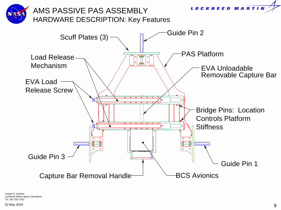
EVA Load Release Screw
EVA Unloadable Removable Capture Bar
Capture Bar Removal Handle
Load Release Mechanism
AMS PASSIVE PAS ASSEMBLY HARDWARE DESCRIPTION: Key Features
Bridge Pins: Location Controls Platform Stiffness
Guide Pin 1
Guide Pin 2
Guide Pin 3
PAS Platform
Scuff Plates (3)
BCS Avionics

Joseph E. KastelicLockheed Martin Space OperationsTel. 281-333-7352
1020 May 2004
AMS PASSIVE PAS ASSEMBLY HARDWARE DESCRIPTION
Low Profile High Misalignment Spherical Bearings
Capture Bar
Guide PIN Contact Surface to GVA
BCS Camera Lens Set

Joseph E. KastelicLockheed Martin Space OperationsTel. 281-333-7352
1120 May 2004
AMS PASSIVE PAS ASSEMBLY HARDWARE DESCRIPTION
AMS Passive PAS is composed of 5 primary sub-assemblies• PAS Base Assembly• PAS Bridge Assembly• EVA Extension Assembly• Capture Bar Assembly• BCS Avionics
Capture Bar Assembly
PAS Bridge Assembly
EVA Extension Assembly
PAS Base Assembly
BCS Avionics

Joseph E. KastelicLockheed Martin Space OperationsTel. 281-333-7352
1220 May 2004
AMS PASSIVE PAS ASSEMBLY HARDWARE DESCRIPTION PAS BASE ASSEMBLY
PAS Base Assembly Components• PAS Platform• Guide Pins• Scuff Plates • Capture Bar Retainer Brackets
Apex Guide Pin
PAS Platform
AFT Guide Pins (2)
Capture Bar Retainer Brackets
AFT Scuff Plates
Apex Scuff Plate

Joseph E. KastelicLockheed Martin Space OperationsTel. 281-333-7352
1320 May 2004
Release Mechanism Housing7075 Al-Alloy, Anodized ExteriorNickel Plated Interior on Scuff Surfaces
AMS PASSIVE PAS ASSEMBLY HARDWARE DESCRIPTIONPAS BRIDGE ASSEMBLY
Wedge15-5 PH CRES
Slip Plate15-5 PH CRES
Release Mechanism Drive Screw½-20UNF-3AA286 Alloy Steel
Bearing Assembly
Bridge7050-T7451 Al-Alloy
Travel Limiter ScrewControls the off-load stoke. This position is preset by unload requirement.
Travel Limiter ScrewControls the set position of the Capture Bar. This position is initially adjusted to “Dial out” tolerance stack-ups and set the Capture Bar to the required position per SSP 57004.

Joseph E. KastelicLockheed Martin Space OperationsTel. 281-333-7352
1420 May 2004
EXTERNAL BERTHING CUES SYSTEM(EBCS) AVIONICS PACKAGE
BCS Avionics PackageMounted to AMS Passive PAS assembly. Camera is aligned to comply with BCS error budget.
BCS Camera Mounting BracketsDesigned and toleranced to comply with SSP 57004 hole mounting pattern.
Joseph E. KastelicLockheed Martin Space OperationsTel. 281-333-7352
1520 May 2004
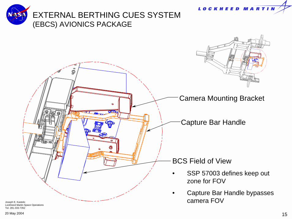
EXTERNAL BERTHING CUES SYSTEM(EBCS) AVIONICS PACKAGE
BCS Field of View • SSP 57003 defines keep out
zone for FOV
• Capture Bar Handle bypasses camera FOV
Capture Bar Handle
Camera Mounting Bracket

Joseph E. KastelicLockheed Martin Space OperationsTel. 281-333-7352
1620 May 2004
AMS PASSIVE PAS ASSEMBLY HARDWARE DESCRIPTIONCAPTURE BAR ASSEMBLY
Capture Bar• A286 Alloy Steel Per AMS 5737• Fracture Critical Part: NDE Dye
Penetrant Inspected to PRC-6506, Type I, Level 3.
Handle Extension• 6061-T6 Aluminum Alloy
Capture Bar Removal Handle (EVA) • 6061-T6 Aluminum Alloy
Handle Base• 15-5PH CRES
Handle Pin• Supports Handle In
PAS coordinate Z
Handle Bushing• Aluminum Bronze Per AMS 9640

Joseph E. KastelicLockheed Martin Space OperationsTel. 281-333-7352
1720 May 2004
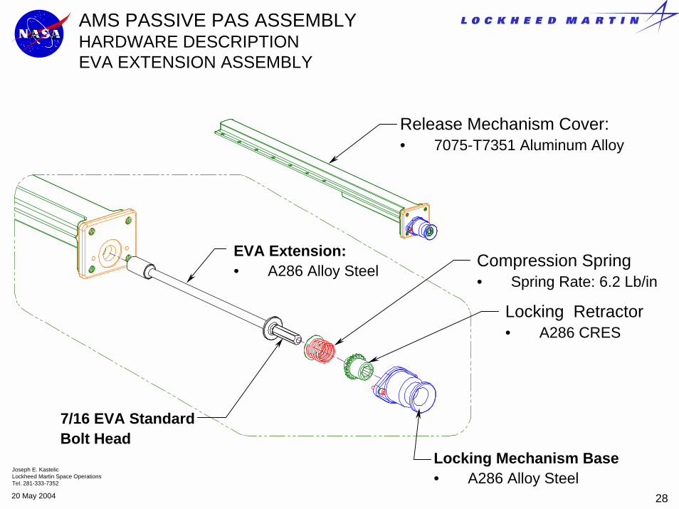
AMS PASSIVE PAS ASSEMBLY HARDWARE DESCRIPTIONEVA EXTENSION ASSEMBLY
EVA Extension:• A286 Alloy Steel
7/16 EVA Standard Bolt Head
Compression Spring• Spring Rate: 6.2 Lb/in
Locking Mechanism Base • A286 Alloy Steel
Locking Retractor• A286 CRES
Release Mechanism Cover:• 7075-T7351 Aluminum Alloy

Joseph E. KastelicLockheed Martin Space OperationsTel. 281-333-7352
1820 May 2004
UMBILICAL MECHANISM ASSEMBLYMOUNTING HARDWARE
UMA BracketUMA Bracket is sized and positioned to tolerances defined in SSP 57004 Section 3.1.2.2 Figure 3.1.2.2-1
EVA Connector Panel Assembly

Joseph E. KastelicLockheed Martin Space OperationsTel. 281-333-7352
1920 May 2004
UMBILICAL MECHANISM ASSEMBLYCONFIGURATION
UMA
EVA Connector Panel
Features• Design shall use a Passive UMA part number 1F70162-1 to interface the
active UMA. Positioned to SSP 57004 Figure 3.1.2.2-1• UMA is attached to Lower USS Via EVA Connector Panel Assembly• UMA Bracket is Positioned and shimmed to meet tight tolerance
requirements defined in SSP 57004• Position and Tolerances are relative to PAS Datum and PAS
feature datum’s
Lower USS
Keel
AMS Passive PAS

Joseph E. KastelicLockheed Martin Space OperationsTel. 281-333-7352
2020 May 2004
AMS Passive PAS EVA Decals
EVA Interfaces and Descriptive Hardware Labels have been developed in accordance with SSP 50005 and JSC 27260C.
Additional requirements were levied per the EVA AIT Crew Consensus Reports, post Low Fidelity NBL Run
AMS PAS Labeling• EVA Capture Bar Handle
• EVA Load Release Screws 1 and 2

Joseph E. KastelicLockheed Martin Space OperationsTel. 281-333-7352
2120 May 2004
AMS PASSIVE PAS EVA DECALSCAPTURE BAR HANDLE
Label Decals
Capture Bar Handle
Capture Bar Handle

Joseph E. KastelicLockheed Martin Space OperationsTel. 281-333-7352
2220 May 2004
AMS PASSIVE PAS EVA DECALSLOAD RELEASE SCREWS
Load Release Screw Identifier
Screw Labeling

Joseph E. KastelicLockheed Martin Space OperationsTel. 281-333-7352
2320 May 2004
PAS SPRING RATE MODEL SPRING RATE SCHEMATIC
PAS Base Assembly
Capture Bar
Bridge Assembly (Adjustable Spring)
Bridge Assembly (Adjustable Spring)
Applied Load from CLA
Guide Pin Guide Pin
PAS Base Assembly: • Fixed Stiffness• Satisfy Geometric I/F RequirementsBridge Assemblies:• Simply Supported C-Channels• Act in Series with PAS Base Assembly• Act in Parallel with each other• Beam Length / Stiffness is adjustable• Contains the Release Mechanism
Joseph E. KastelicLockheed Martin Space OperationsTel. 281-333-7352
2420 May 2004
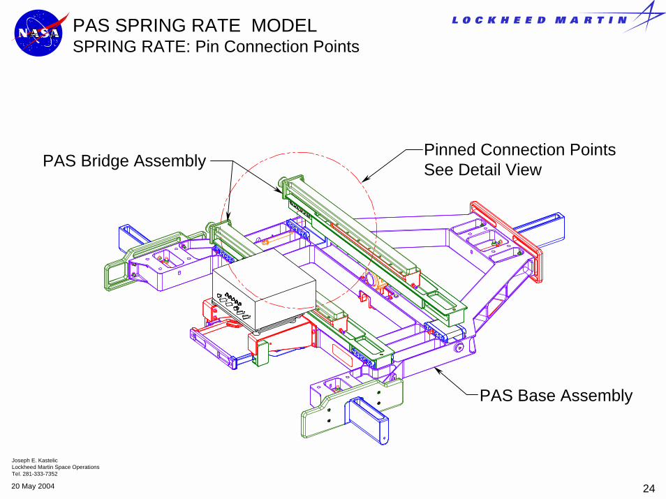
PAS SPRING RATE MODEL SPRING RATE: Pin Connection Points
PAS Base Assembly
PAS Bridge Assembly Pinned Connection Points See Detail View

Joseph E. KastelicLockheed Martin Space OperationsTel. 281-333-7352
2520 May 2004
PAS SPRING RATE MODEL ADJUSTABLE SPRING RATE
Bridge Assembly
PAS Base Assembly
Bridge BracketsBracket has three mounting locations (A,B,and C) to PAS Base and six pin hole locations providing a total of 18 beam length options
Bridge Pin
Six Pin Position Options

Joseph E. KastelicLockheed Martin Space OperationsTel. 281-333-7352
2620 May 2004
PAS SPRING RATE MODELPREDICTED PAS STIFFNESS VS PIN LOCATION
PAS Stiffness vs Pin Location
1000011000120001300014000150001600017000180001900020000
1 2 3 4 5 6
Pin Number
Sti
ffn
ess
(lb
f/in
)
StiffnessNASTRAN
6 C 27.5 186186 B 28.0 179556 A 28.5 173985 C 29.0 169135 B 29.5 164725 A 30.0 160564 C 30.5 156504 B 31.0 152464 A 31.5 148393 C 32.0 144283 B 32.5 14016
3 A 33.0 136042 C 33.5 131972 B 34.0 127972 A 34.5 124081 C 35.0 120291 B 35.5 116561 A 36.0 11283
System Stiffness
Pin Number
Bridge Length
Bushing
Note: Spring Rate Requirement is 13500 +/- 10% (SSP 57003)

Joseph E. KastelicLockheed Martin Space OperationsTel. 281-333-7352
2720 May 2004
PASSIVE PAS STATIC TEST
Static Test Description: The AMS Passive PAS Static Test was conducted to achieve the following objectives:
• To Correlate the NASTRAN model with the flight hardware in terms of stiffness and stress
• To demonstrate the Maximum Preload Capability
• To “set” the PAS stiffness as close as possible to the required stiffness per SSP 57003
• To demonstrate the ability to off-load the Capture Bar Preload using the Capture Bar Release Mechanism
• To use the adjustability of the spring system to level the Capture Bar
• To Determine the Final Configuration

Joseph E. KastelicLockheed Martin Space OperationsTel. 281-333-7352
2820 May 2004
AMS Passive PAS Static Test
AMS Passive PAS Assembly: SEG39135815-301

Joseph E. KastelicLockheed Martin Space OperationsTel. 281-333-7352
2920 May 2004
AMS PASSIVE PAS STATIC TEST
AMS Passive PAS
USS Simulator
AMS Passive PAS with USS Simulator: Test Configuration

Joseph E. KastelicLockheed Martin Space OperationsTel. 281-333-7352
3020 May 2004
AMS PASSIVE PAS STATIC TEST
Test Fixture Assembly
PAS Assembly with Simulator
AMS Passive PAS with USS Simulator: Assembly On Test Stand

Joseph E. KastelicLockheed Martin Space OperationsTel. 281-333-7352
3120 May 2004
PASSIVE PAS STATIC TESTFINAL CONFIGURATIONFINAL SPRING RATE
Capture Bar Loaded to 5650 Nominal Preload to determine Spring Rate
Final Pin Position Criteria:• Spring rate as Close to nominal as possible
• Level Capture Bar
Fitting a Least Squares straight line to the data between 500 LBF and 5650 LBF
Spring Rate: K = 13568 LBF/IN
Capture Bar Angle (How Level) Tested Load: 6.3867e+003 Delta: .020146 inches Angle of C/B at max pre-load: .0996 Degrees

Joseph E. KastelicLockheed Martin Space OperationsTel. 281-333-7352
3220 May 2004
AMS PAS Interface Verification Test (IVT)March, 2003
Test Procedure Summary:• The AMS Passive PAS was lifted to the Upper Inboard PAS
number 2 Active PAS site• The PAS 2 Capture Claw was closed on the AMS PAS
Capture Bar• The preload at full closure was measured• The proximity of the PAS Capture Bar Mounting hardware to
the EBCS Target Assembly was measured at Loaded Condition.
• The AMS Passive PAS Release Mechanism was used to unload the Capture Claw Preload. Proximity to Target was measured in Unloaded Condition
• The Capture Bar was removed demonstrating the required contingency capability to unload and remove the payload

Joseph E. KastelicLockheed Martin Space OperationsTel. 281-333-7352
3320 May 2004
IVT Test Test Configuration
USS Simulator
AMS Passive PAS
IVT Configuration was identical to the AMS PAS Static Test

Joseph E. KastelicLockheed Martin Space OperationsTel. 281-333-7352
3420 May 2004
IVT TestLifting
AMS Passive PAS being lifted to the S3 Truss

Joseph E. KastelicLockheed Martin Space OperationsTel. 281-333-7352
3520 May 2004
IVT TestBerthing
The AMS Passive PAS on Berthing Approach to PAS site 2

Joseph E. KastelicLockheed Martin Space OperationsTel. 281-333-7352
3620 May 2004
IVT TestBerthed
The AMS Passive PAS Berthed to the S3 Active PAS 2
Capture Bar
Capture Claw

Joseph E. KastelicLockheed Martin Space OperationsTel. 281-333-7352
3720 May 2004
IVT TestEVA Unload
Removing the Preload with the EVA Release Mechanism

Joseph E. KastelicLockheed Martin Space OperationsTel. 281-333-7352
3820 May 2004
AMS IVTUNLOADING AND REMOVING THE CAPTURE BAR
Requirements• To Relieve the Capture Bar Preload Completely.
• SSP 57003 requires a minimum unload stroke of .71 inches
• To remove the Capture Bar from the Capture Claw
Results of Load Removal TestThe AMS Capture Bar was Lowered .71 inches as required using the AMS PAS Load release Mechanism Assembly. A visible gap of .033 was measured guaranteeing a Zero Preload
The Capture Bar was retracted Completely through the CLA and The payload was hoisted off of the S3 Truss.
Capture Bar lowered and retracted axially through the Bearing Assembly

Joseph E. KastelicLockheed Martin Space OperationsTel. 281-333-7352
3920 May 2004
AMS IVTCONCLUSIONS
• Preload was shown to be within 3.2 percent of the nominal load value defined in SSP 57003 Section 3.1.3.1.3.1
• Nominal Preload expected 5650 lb: Actual 5470 lb
• Capture Bar was Unloaded and removed from the CLA
• The preload was removed with a .71 inch stroke as specified in SSP 57003 Section 3.1.3.2.1 A visible Gap was measured
• The Loaded Capture Bar Proximity to BCS Target was within the AP envelope defined in SSP 57003 Section 3.1.3.1.1.1
• The Unloaded Proximity to the BCS Target was within AP Envelope Limits described in SSP 57003 Section 3.1.3.1.1.1

Joseph E. KastelicLockheed Martin Space OperationsTel. 281-333-7352
4020 May 2004
AMS PASSIVE PAS FUTURE TESTING
Possible Thermal Chamber Test Demonstrating the Preload and the Unloadable Releasable Capture Bar function at Operating extremes of –120 Deg. F to 200 Deg. F
ACAS test (Active Common Attach Simulator): To support Pre-flight Checkout of the physical and functional interfaces of thePayload Attach System (PAS).

Joseph E. KastelicLockheed Martin Space OperationsTel. 281-333-7352
4120 May 2004
PAGE INTENTIONALLY LEFT BLANK

Joseph E. KastelicLockheed Martin Space OperationsTel. 281-333-7352
120 May 2004
AMS PASSIVE PAS CDR SUPPORTING INFORMATION CONTENTS
• Primary Design Requirement Documents• Summary of Interface Requirements• AMS Passive PAS Assembly Hardware Description• EBCS Avionics Package• Passive PAS Spring Rate Model• Static Test• Interface Verification Test• As-Built Dimensions

Joseph E. KastelicLockheed Martin Space OperationsTel. 281-333-7352
220 May 2004
PRIMARY REQUIREMENTS DOCUMENTS
• SSP 57003 Attached Payload Interface Requirements Document: Current Revision A
• SSP 57004 Attached Payload Hardware ICD Template: Current Revision A
• SSP 42131 Space Station Program Integrated Truss Segments P3 andS3 to Attached Payloads and Unpressurized Cargo Carriers (UCC) Standard Interface Control Document: Current Revision D
• SSP 57213 Unique Payload ICD
SSP 57213

Joseph E. KastelicLockheed Martin Space OperationsTel. 281-333-7352
320 May 2004
SUMMARY OF INTERFACE REQUIREMENTSEXCERPTS FROM SSP 57004 IR TEMPLATE
- B -
8.50
23.14MAX (9.360)
11.45 MAX
35.45 MIN
(33.775)
30.550
23.450 30.550
.010 A
(1.450 )
- C -
.010 A B
41.000
49.00MIN
(1.450 )
.028 B C
- E -
(1.450 )
.020 E CS
.028 B C
31.14MIN
A A
CLEARANCEFOR LATCHMECHANISM9.8 INCHDEEP (MIN)FROM - A -
B
B
C
- D -
GuidePin 1
(5.750)
(2.858)
.017
13.857(9.500)
EBCS CameraAttach Interface
S
S
S
GuidePin 3
GuidePin 2
Y
X
IR Template:Defines the Physical geometry Required to I/F Common Attach Sites
View Shows:• Basic Sizing With
Tolerances• BCS keep Out
Zones• BCS Mounting
Locations• UMA Sizing and
Positioning requirements

Joseph E. KastelicLockheed Martin Space OperationsTel. 281-333-7352
420 May 2004
SUMMARY OF INTERFACE REQUIREMENTSEXCERPTS FROM SSP 57004 IR TEMPLATE.
- A -
.015
3 GUIDE PINS
3.534
30.432(7.414)
POTENTIAL CONTACTAREAS (TYP 3 PLACES) R .25 MIN
(CONTACT AREA)
16.0 MIN4
5.414
Camera Mounting Plan
4
Z
XView Shows:• Platform height
With Tolerances• BCS camera
Mounting Plane • Scuff Plate Sizing• UMA Sizing
Positioning requirements
46.900
3.534
30.282
(7.714)

Joseph E. KastelicLockheed Martin Space OperationsTel. 281-333-7352
520 May 2004
SUMMARY OF INTERFACE REQUIREMENTSEXCERPTS FROM SSP 57004 IR TEMPLATE
- A -
1.142 ± .005 1
Ø1.5051.495
.020 D SM
SECTION A - A(CAPTURE BAR)
3 4
- A - 3.75 MIN
R .725
.688
1.450
VIEW B - B(GUIDE PIN DETAIL - TYPICAL 3 PLACES)
5
4
( - E - )
.004 A E
A
B
CD
FROM A TO B
.004 A E
FROM C TO D
6
1
2.
DIMENSION IS BASED ON SYSTEM PRELOAD REQUIREMENT 3.3.1.2.1.2.1.
SEE FIGURE 3.3.1-2 FOR THE ENTIRE PASSIVE HALF OPERATIONAL ENVELOPE.
3 SURFACE ROUGHNESS 63 MICROINCHES PER ANSI B46.1-1985.
4 APPLY MIL-L-46010, TYPE I LUBRICANT.
5 SURFACE SHALL BE FREE OF DRYLUBE. PASSIVATE PER QQ-P-35 IF CRES,OR CHEMICAL CONVERSION SURFACE PER MIL-C-5541, CLASS 3 IF ALUMINUM.
6APPLIES TO HEIGHT OF GUIDE PIN ONLY.PLATFORM HEIGHT IS DEPENDENT UPON SYSTEM PRELOAD REQUIREMENT 3.3.1.2.1.2.1.
View Shows:• Guide Pin Sizing
and tolerances• Capture Bar Sizing
and Tolerances

Joseph E. KastelicLockheed Martin Space OperationsTel. 281-333-7352
620 May 2004
SUMMARY OF INTERFACE REQUIREMENTS EXCERPTS FROM SSP 57004 IR TEMPLATE
(30.282) 7.714
1.126 1.126
.135
- A -
(3.534)
- D -
9.360- F -
.361
.361
2.00MIN
.16 X .16CHAMFER
2 PL
VIEW C(UMA MOUNTING BRACKET)
.614
- E -
33.775
8.36 ± .07
1.00 ± .07
8.65 ± .07.55 ± .07
SECTION D-D
D
D
2.25 MAX
.010 E
1.35"
UMA OperationalKeep Out Zone
(4.650)UMA ActiveCenterline
View Shows:• UMA sizing and
Positioning

Joseph E. KastelicLockheed Martin Space OperationsTel. 281-333-7352
720 May 2004
SUMMARY OF INTERFACE REQUIREMENTS EXCERPTS FROM SSP 57004 IR TEMPLATE
(30.432)
7.414
.976 .976
.135
- A -
(3.534)- D -
.614
4X Ø .078 THRU
Ø X 90° FS.15.12
Ø .014 G M
Ø X R.02 MAX .288
Ø .008 S
.535
.530
Ø .340Ø .020 G S A F S
- G -
F
.014 A F2X2X 30° ± 1°
2X .325.040 X .040CHAMFER
E
VIEW E (4 PLCS)SECTION F-F
F
F
Ø .014 D S A F S
M
M
M
S
View Shows:• UMA sizing and
Positioning

Joseph E. KastelicLockheed Martin Space OperationsTel. 281-333-7352
820 May 2004
AMS PASSIVE PAS ASSEMBLY HARDWARE DESCRIPTION
Key Features• Guide Pins: Interface CAS Guide Vanes• Scuff Plates: Berthing Operations• BCS Avionics: Facilitate Berthing Operations• Capture Bar • Capture Bar Handle for EVA Contingency Operations• EVA Load Release Screw• Adjustable Spring Rate

Joseph E. KastelicLockheed Martin Space OperationsTel. 281-333-7352
920 May 2004
AMS PASSIVE PAS ASSEMBLY HARDWARE DESCRIPTION
AMS Passive PAS is composed of 5 primary sub-assemblies• PAS Base Assembly• PAS Bridge Assembly• EVA Extension Assembly• Capture Bar Assembly• BCS Avionics
Capture Bar Assembly
PAS Bridge Assembly
EVA Extension Assembly
PAS Base Assembly
BCS Avionics Camera
Camera Mounting Brackets

Joseph E. KastelicLockheed Martin Space OperationsTel. 281-333-7352
1020 May 2004
AMS PASSIVE PAS ASSEMBLY HARDWARE DESCRIPTION PAS BASE ASSEMBLY
PAS Base Assembly Components• PAS Platform Assembly• Guide Pins• Scuff Plates • Capture Bar Retainer Brackets
Apex Guide Pin
PAS Platform
AFT Guide Pins (2)
Capture Bar Retainer Brackets
AFT Scuff Plates
Apex Scuff Plate

Joseph E. KastelicLockheed Martin Space OperationsTel. 281-333-7352
1120 May 2004
AMS PASSIVE PAS ASSEMBLY HARDWARE DESCRIPTION PAS PLATFORM ASSEMBLY
Drawing SEG39135817-301: • Machined Aluminum 7050-T7451• Ultrasonic and Fatigue Tested Material per BMS-7-323-C• Clear Anodized to PRC 5006 Type II, Class 1• Interface areas Nickel Plated to AMS3451/3 per AMS Process Control
Drawing SKG39135893

Joseph E. KastelicLockheed Martin Space OperationsTel. 281-333-7352
1220 May 2004
AMS PASSIVE PAS ASSEMBLY HARDWARE DESCRIPTION PAS PLATFORM ASSEMBLY
Platform Design Considerations:• Deflection Curve: Platform is a critical component of the total overall spring rate.
Finite element model was the primary driver in specifying wall thickness and pocket locations.
• Tolerance Requirements: Tight tolerance requirements specified in SSP 57004 suggested a single machined component as opposed to built up structure.
Top View
USS Attachment Bracket Interface: Nickel Plated
USS Attachment Bracket Interface: Nickel Plated
Scuff Plate Interface: Nickel Plated 3 Places

Joseph E. KastelicLockheed Martin Space OperationsTel. 281-333-7352
1320 May 2004
Guide Pins• Machined Aluminum Alloy 7050-T7451• Clear Anodized to PRC 5006 Type II, Class 1• Interface areas Nickel Plated to AMS3451/3
per AMS Process Control Drawing SKG39135893
Nickel Plating: This area is the primary grounding contact area to the PAS Platform
Nickel Plating: This area contacts the Active Guide Vane Assemblies and acts as the grounding path for a class R bond for the AMS structure. A requirement per SSP42131section 3.3.2.1.3.1.1.
AMS PASSIVE PAS ASSEMBLY HARDWARE DESCRIPTIONGUIDE PINS

Joseph E. KastelicLockheed Martin Space OperationsTel. 281-333-7352
1420 May 2004
AMS PASSIVE PAS ASSEMBLY HARDWARE DESCRIPTIONGUIDE PINS
Guide Pin Profile Geometry• Guide Pin Height and Length requirements prevent
interference to ITS Longeron and CAS Guide Vane RTL.• Geometric requirements Per SSP 57003, SSP 57004.• Apex Guide Pin Length 8.50 in. Per SSP 57004 Section
3.1.2.2. Requirement Relative to PAS datum C.• Aft Guide Pin Length 7.10 in. Per SSP 57004 Section
3.1.2.2. Requirement to PAS datum B.

Joseph E. KastelicLockheed Martin Space OperationsTel. 281-333-7352
1520 May 2004
AMS PASSIVE PAS ASSEMBLYHARDWARE DESCRIPTIONGUIDE PINS
Guide Pin Profile Per SSP 57004 Section 3.1.2.2 Figure 3.1.2.2-1

Joseph E. KastelicLockheed Martin Space OperationsTel. 281-333-7352
1620 May 2004
AMS PASSIVE PAS ASSEMBLYHARDWARE DESCRIPTIONSCUFF PLATES
Everlube 812 Dry Film Lubricated Surface.
• This surface acts as a potential contact surface to CAS guide Vane Assemblies during Berthing Operations
Nickel Plated interfaces to PAS Platform. Process per JSC PRC 5007
Apex Scuff Plate
Aft Scuff Plate
Features• Machined Aluminum 7075-T7351• Clear Anodized to PRC 5006 Type II,
Class 1. • Dry Film coated on scuff surface per
SSP 57004 Section 3.1.2.2

Joseph E. KastelicLockheed Martin Space OperationsTel. 281-333-7352
1720 May 2004
AMS PASSIVE PAS ASSEMBLY HARDWARE DESCRIPTIONCAPTURE BAR RETAINER BRACKETS
Brackets serve three purposes.• Add stiffness to the PAS Platform.• Maintains alignment of the Capture
Bar per SSP 57004 section 3.1.2.2.• Provides the keying feature that locks
the Capture Bar in position until the bar is unloaded.
Aft Alignment Bracket
• Machined 15-5 PH age hardened to H1025 per NASA JSC PRC 2001. Passivated to PRC 5002 Type VI.
Apex Alignment Bracket
Capture Bar Keying feature

Joseph E. KastelicLockheed Martin Space OperationsTel. 281-333-7352
1820 May 2004
AMS PASSIVE PAS ASSEMBLY HARDWARE DESCRIPTION PAS BASE ASSEMBLY METHOD
• PAS Base Assembly serves to meet the Static Interface Requirements of SSP 57004 Section 3.1.2.2
• Guide Pins are shimmed, aligned, and pinned at the assembly level.
• Capture Bar Retainer Brackets are aligned, match drilled, and positioned using NAS6704U10 close tolerance hex head screws.
• Scuff Plates maintain geometric compliance to SSP 57004 by machining tolerances.

Joseph E. KastelicLockheed Martin Space OperationsTel. 281-333-7352
1920 May 2004
AMS PASSIVE PAS ASSEMBLY HARDWARE DESCRIPTIONPAS BASE ASSEMBLY METHOD
3/8-24 UNJF Socket Head Cap Screws. (4) required per pin
Sheer Pins. 2 required. Guide Pin is shimmed, aligned, match drilled, and pinned to meet I/F requirements.
Aluminum Shim Stock, peel type, .002 inch layers per SAE-AMS-DTL-22499 ¼-28UNJF SHCS Preload
maintains electrical bond between PAS Platform and Guide Pin surfaces.

Joseph E. KastelicLockheed Martin Space OperationsTel. 281-333-7352
2020 May 2004
AMS PASSIVE PAS ASSEMBLY HARDWARE DESCRIPTIONPAS BASE ASSEMBLY METHOD
Close Tolerance Screw
Brackets Aligned, Match drilled, and fixed using Close Tolerance Hex Head Screw NAS6704U10
Close Tolerance Screw

Joseph E. KastelicLockheed Martin Space OperationsTel. 281-333-7352
2120 May 2004
AMS PASSIVE PAS ASSEMBLY HARDWARE DESCRIPTIONPAS BRIDGE ASSEMBLY
Components• Bridge• Release Mechanism
Assembly– Housing– Bearing Assembly – Wedge– Slip Plate– Drive Screw
Release Mechanism Assembly: SSP 57003 Requires an Unloadable Releasable Capture Bar. Release Mechanism allows the removal of preload using the a retractable wedge.
PAS Bridge: A primary component of the AMS Passive PAS Spring System. Bridge Supports are adjustable allowing control of spring rate.
Spherical Bearing Assembly The support structure for the Capture bar

Joseph E. KastelicLockheed Martin Space OperationsTel. 281-333-7352
2220 May 2004
AMS PASSIVE PAS ASSEMBLY HARDWARE DESCRIPTIONPAS BRIDGE ASSEMBLY
Top View of Release Mechanism mounted in Bridge
Wedge shown in Set Position as defined in SSP 57004Capture Bar 1.142 +/- .005 from PAS Datum Z
Wedge Position shown retracted and in lowered position (.71 inch minimum unload stroke per SSP 57003) Mechanism has a one inch stroke capability.
A
B B
A

Joseph E. KastelicLockheed Martin Space OperationsTel. 281-333-7352
2320 May 2004
AMS PASSIVE PAS ASSEMBLY HARDWARE DESCRIPTIONPAS BRIDGE ASSEMBLY Section A
Bearing (Capture Bar) in Set Position
Bearing (Capture Bar) in Lowered Position
Section B
Section view shows workings of Release Mechanism. 10 Degree Wedge shown set with bearing at required 1.142 inches from PAS Datum in Z direction. Wedge bears against Upper Travel Limiter.
Section view shows Release mechanism retracted in lowered position. Wedge bears against Lower Travel Limiter.

Joseph E. KastelicLockheed Martin Space OperationsTel. 281-333-7352
2420 May 2004
AMS PASSIVE PAS ASSEMBLY HARDWARE DESCRIPTIONPAS BRIDGE ASSEMBLY
Release Mechanism drive Screw
Bellville WashersProvides Preload on Drive Screw
Drive Screw BushingAluminum Bronze per AMS 9640
Bearing Assembly Shaft
Wedge Nut Electro-polished 15-5 PH. 10 degree angle applies Capture Bar preload to Wedge.

Joseph E. KastelicLockheed Martin Space OperationsTel. 281-333-7352
2520 May 2004
AMS PASSIVE PAS ASSEMBLY HARDWARE DESCRIPTIONPAS BRIDGE ASSEMBLY
Spherical Bearing Assembly
Bearing Housing
Bearing Housing Cover
Bearing Assembly Description• Provide Bearing support and
Load Transfer from CLA to PAS Assembly
• Supports Capture Bar• Spherical Bearings allow
Capture Bar angular movement upon load release

Joseph E. KastelicLockheed Martin Space OperationsTel. 281-333-7352
2620 May 2004
AMS PASSIVE PAS ASSEMBLY HARDWARE DESCRIPTIONPAS BRIDGE ASSEMBLY
Bearing HousingMachined Age Hardened 15-5 PH CRESFracture Critical Part: NDE Dye Penetrant Inspected per PRC 6506, Type 1, level 3.
Spherical Bearing AssemblyLow Profile OD (2.4375 in)Maximum Misalignment Inner Race (5.3 Degrees)
Bearing Housing Cover Machined Age Hardened 15-5 PH per AMS 5659

Joseph E. KastelicLockheed Martin Space OperationsTel. 281-333-7352
2720 May 2004
AMS PASSIVE PAS ASSEMBLY HARDWARE DESCRIPTIONCAPTURE BAR ASSEMBLY
OD 1.50 Inches
Key Groove to retain Capture Bar while under CLA Preload
Machined Capture Bar Retainer Groove
Joseph E. KastelicLockheed Martin Space OperationsTel. 281-333-7352
2820 May 2004
AMS PASSIVE PAS ASSEMBLY HARDWARE DESCRIPTIONEVA EXTENSION ASSEMBLY
EVA Extension:• A286 Alloy Steel
7/16 EVA Standard Bolt Head
Compression Spring• Spring Rate: 6.2 Lb/in
Locking Mechanism Base • A286 Alloy Steel
Locking Retractor• A286 CRES
Release Mechanism Cover:• 7075-T7351 Aluminum Alloy

Joseph E. KastelicLockheed Martin Space OperationsTel. 281-333-7352
2920 May 2004
AMS PASSIVE PAS ASSEMBLYHARDWARE DESCRIPTIONEVA EXTENSION ASSEMBLY
DescriptionPGT engagement of EVA Extension Depresses Locking Mechanism. The action presses against spring. Retractor movement disengages gear from fixed teeth and is free to rotate

Joseph E. KastelicLockheed Martin Space OperationsTel. 281-333-7352
3020 May 2004
EXTERNAL BERTHING CUES SYSTEM(EBCS) AVIONICS PACKAGE
EBCS Avionics• BCS Provide Visual cues to robotic workstation monitors to assist ISS Mobile Servicing
System operators in berthing ISS external payloads.
• System is comprised of an Avionics Package which contains primary, secondary video cameras, and a BCS Target which is mounted on the CAS site.
• BCS Avionics mounting is the responsibility of the attached payload.
• Mounting Requirements are defined in SSP 57003 section 3.7.6.1, SSP 57004 figures 3.1.2.2-1 and SSP 57004 figures 3.7.1-1. Additional data per MDR-BCS-SG-5822 Development Specification produced by MD Robotics per NASA contract NAS9-00089.
• BCS Electrical Services include video, video sync, power, heater power, and payload power.

Joseph E. KastelicLockheed Martin Space OperationsTel. 281-333-7352
3120 May 2004
PAS SPRING RATE MODELOVERVIEW
The AMS Passive PAS is a design solution for the passive half of the Common Attach System. It’s primary purpose is secure an attached payload to the Passive Integrated Truss Segment Payload Attach Site located on the S3 Truss of the International Space Station. It is an assembly produced to provide a solution to a number of simultaneous geometric and performance based requirements defined in Space Station Documents SSP 57003 and SSP 57004.
In an effort to accommodate the stringent spring rate criteria defined in SSP 57003 and to allow for future variations in this requirement the design allows for the adjustability of the spring rate using a simple variable length beam principle. This section summarizes the design criteria, the predicted values, and the as-built tested results.

Joseph E. KastelicLockheed Martin Space OperationsTel. 281-333-7352
3220 May 2004
PAS SPRING RATE MODEL SPRING RATE SCHEMATIC
The AMS Passive PAS utilizes the predictable nature of simply supported beams with the ability to control the support locations on each beam.
The system is comprised of a machined platform of a fixed geometry that acts to satisfy the geometric interface requirements of SSP 57003, with two variable geometry Bridge Beams in a series configuration with the PAS platform. The beams act in a parallel configuration with each respective beam. The Primary components to the spring system are the PAS Base and the Bridge Assemblies.
PAS Base Assembly
Capture BarBridge Assembly (Adjustable Spring)
Bridge Assembly (Adjustable Spring)
Applied Load from CLA
Guide Pin Guide Pin

Joseph E. KastelicLockheed Martin Space OperationsTel. 281-333-7352
3320 May 2004
PAS SPRING RATE MODELPAS BASE ASSEMBLY
Platform Features• The PAS Platform acts as the primary geometry that interfaces the Active PAS.
It serves to support the Bridge Assemblies with a pinned connection.
• The Bridge assemblies are attached to the Platform using 4 PAS Base Bridge Brackets. These brackets have three possible mounting locations on the PAS Platform. Location A, B, and C.
Pas Base Bridge Brackets

Joseph E. KastelicLockheed Martin Space OperationsTel. 281-333-7352
3420 May 2004
PAS SPRING RATEPAS BASE ASSEMBLYPAS BASE BRIDGE BRACKETS
PAS Bridge PinOne per bracket
Six Possible Pin Locations
PAS Base Bridge Brackets

Joseph E. KastelicLockheed Martin Space OperationsTel. 281-333-7352
3520 May 2004
PAS Bridge Bracket positions A, B, and CEach Position Offsets the Bridge Bracket by.25 inches changing the overall span by .5 inches for a symmetrical system
A BC
A BC
PAS SPRING RATE PAS BASE ASSEMBLY BRACKET MOUNTING OPTIONS

Joseph E. KastelicLockheed Martin Space OperationsTel. 281-333-7352
3620 May 2004
PAS SPRING RATE MODELPAS BASE ASSEMBLY BRACKET MOUNTING OPTIONS
PAS Bridge End Connection Options

Joseph E. KastelicLockheed Martin Space OperationsTel. 281-333-7352
3720 May 2004
PAS SPRING RATE MODELPAS BRIDGE ASSEMBLIES
The PAS Bridge Assemblies• Function as the Secondary Spring System
• Bridge Span (Spring rate) is adjustable
• Fixed Via pinned connections to PAS Base Assembly
PAS Bridge Assemblies

Joseph E. KastelicLockheed Martin Space OperationsTel. 281-333-7352
3820 May 2004
PAS SPRING RATE MODELPAS BRIDGE ASSEMBLIES
Bridge Flat Bearing
PAS Base Bridge Bracket
PAS Bridge Assembly

Joseph E. KastelicLockheed Martin Space OperationsTel. 281-333-7352
3920 May 2004
PAS SPRING RATE MODELPREDICTED PAS STIFFNESS VS PIN LOCATION
PAS Stiffness vs Pin Location
1000011000120001300014000150001600017000180001900020000
1 2 3 4 5 6
Pin Number
Sti
ffn
ess
(lb
f/in
)
StiffnessNASTRAN
6 C 27.5 186186 B 28.0 179556 A 28.5 173985 C 29.0 169135 B 29.5 164725 A 30.0 160564 C 30.5 156504 B 31.0 152464 A 31.5 148393 C 32.0 144283 B 32.5 14016
3 A 33.0 136042 C 33.5 131972 B 34.0 127972 A 34.5 124081 C 35.0 120291 B 35.5 116561 A 36.0 11283
System Stiffness
Pin Number
Bridge Length
Bushing
Note: Spring Rate Requirement is 13500 +/- 10% (SSP 57003)

Joseph E. KastelicLockheed Martin Space OperationsTel. 281-333-7352
4020 May 2004
PAS SPRING RATE MODELPREDICTED RESOLUTION OF SPRING RATE
StiffnessNASTRAN
6 C 27.5 18618 663 331.56 B 28.0 17955 557 278.56 A 28.5 17398 485 242.55 C 29.0 16913 441 220.55 B 29.5 16472 416 2085 A 30.0 16056 406 2034 C 30.5 15650 404 2024 B 31.0 15246 407 203.54 A 31.5 14839 411 205.53 C 32.0 14428 412 2063 B 32.5 14016 412 206
3 A 33.0 13604 407 203.52 C 33.5 13197 400 2002 B 34.0 12797 389 194.52 A 34.5 12408 379 189.51 C 35.0 12029 373 186.51 B 35.5 11656 373 186.51 A 36.0 11283
ResolutionResolution:
Staggered Pins lb/in (.25 inch offset)
System Stiffness Predicted
Pin Number
Bridge Length
Bushing
Refined resolutions with an asymmetrical change in pin location. (Example:Apex Bridge pins are located in the adjacent pin position .25 inches offset from the Aft Bridge: Apex Bridge Location 6A, Aft Pin location in 6B)
Note: further Refinement could be done staggering the pin locations on each separate bridge ( Example: Aft Bridge Left Pin in 6A, right Pin in 6B)
Predicted change in spring rate with a symmetrical change in pin location. (Each Pin is in the same position)

Joseph E. KastelicLockheed Martin Space OperationsTel. 281-333-7352
4120 May 2004
PREDICTED CAPTURE BAR DEFLECTION
Design Criteria:
• Maximum Preload: 6430 LB *
• Minimum Preload: 4900 LB *
• Nominal Preload: 5650 LB
• Nominal Stiffness 13500 +/- 10% **
• Nominal Capture Bar Deflection 5650/13500 LB = .419 inches (Total Deflection of the Capture Bar)
*per SSP 57003 Section 3.1.3.1.3.1
**per SSP 57003Section 3.1.3.1.3.2

Joseph E. KastelicLockheed Martin Space OperationsTel. 281-333-7352
4220 May 2004
PREDICTED CAPTURE BAR DEFLECTION BASED ON SYMMETRICAL PIN SPACING
Capture Bar
-0.700
-0.600
-0.500
-0.400
-0.300
-0.200
-0.100
0.000D
efle
ctio
n (in
che) Pin 1
Pin 2Pin 3Pin 4Pin 5Pin 6
CLA Contact Point
APEX Bridge AFT Bridge
Note: Capture Bar Deflects More in the Apex Bridge due to Platform effects. This suggests an effort to level the Capture Bar upon loading using offset pin locations.

Joseph E. KastelicLockheed Martin Space OperationsTel. 281-333-7352
4320 May 2004
PASSIVE PAS STATIC TEST
Static Test Description: The AMS Passive PAS Static Test was conducted to achieve the following objectives:
• To Correlate the NASTRAN Model with the flight hardware in terms of stiffness and stress.
• To demonstrate the Maximum Preload Capability
• To “set” the PAS stiffness as close as possible to the required stiffness per SSP 57003
• To demonstrate the ability to off-load the Capture Bar Preload using the Capture Bar Release Mechanism .
• To use the adjustability of the spring system to level the Capture Bar.
• To Determine the Final Configuration

Joseph E. KastelicLockheed Martin Space OperationsTel. 281-333-7352
4420 May 2004
PASSIVE PAS STATIC TESTCorrelate the NASTRAN Model with the flight hardware in terms of stiffness.
Graph shows Capture Bar Loaded to 2000 LBS. Deflection is at center of Capture Bar.
Pins Located at Location 1A (Softest)
Approximate Spring Rate: Using Least Squares Fit: SR = 10837 lb/inPredicted Value: 11283 Lb/in (4% variation)
SOFTEST PIN SETTINGLoad VS Deflection

Joseph E. KastelicLockheed Martin Space OperationsTel. 281-333-7352
4520 May 2004
PASSIVE PAS STATIC TESTCorrelate the NASTRAN Model with the flight hardware in terms of stiffness.
Graph shows Capture Bar Loaded to 2000 LBS. Deflection is at center of Capture Bar.
Pins Located at Location 6A (Stiffest)
Approximate Spring Rate: Using Least Squares Fit: SR = 17538 lb/inPredicted Value: 17398 Lb/in.80% variation
STIFFEST PIN SETTINGLoad VS Deflection

Joseph E. KastelicLockheed Martin Space OperationsTel. 281-333-7352
4620 May 2004
PASSIVE PAS STATIC TESTCAPTURE BAR LOADED TO 6430 LB MAXIMUM PRELOADOFFLOADING USING RELEASE MECHANISM
Load VS Deflection
Unloaded to Zero using PAS Release Mechanism
Max Preload defined in SSP 57003 Section 3.1.3.1.3.1
Loaded to 6430 lb
Joseph E. KastelicLockheed Martin Space OperationsTel. 281-333-7352
4720 May 2004
PASSIVE PAS STATIC TESTFINAL CONFIGURATION
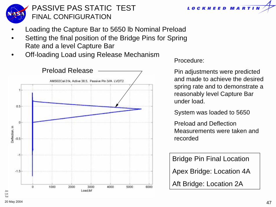
• Loading the Capture Bar to 5650 lb Nominal Preload• Setting the final position of the Bridge Pins for Spring
Rate and a level Capture Bar• Off-loading Load using Release Mechanism
Procedure:
Pin adjustments were predicted and made to achieve the desired spring rate and to demonstrate a reasonably level Capture Bar under load.
System was loaded to 5650
Preload and Deflection Measurements were taken and recorded
Preload Release
Bridge Pin Final Location
Apex Bridge: Location 4A
Aft Bridge: Location 2A

Joseph E. KastelicLockheed Martin Space OperationsTel. 281-333-7352
4820 May 2004
PASSIVE PAS STATIC TESTFINAL CONFIGURATIONFINAL PIN SETTINGS FOR A LEVEL CAPTURE BAR
Deflection of Capture Bar Aft Bearing (LVDT 5)
Deflection of Capture Bar Apex Bearing (LVDT 6)
Tested Load: 6.3867e+003
Delta Deflection: .020146
Angle of Capture Bar at Load:
.0996 Degrees
Joseph E. KastelicLockheed Martin Space OperationsTel. 281-333-7352
4920 May 2004
PASSIVE PAS STATIC TESTFINAL CONFIGURATIONFINAL SPRING RATE
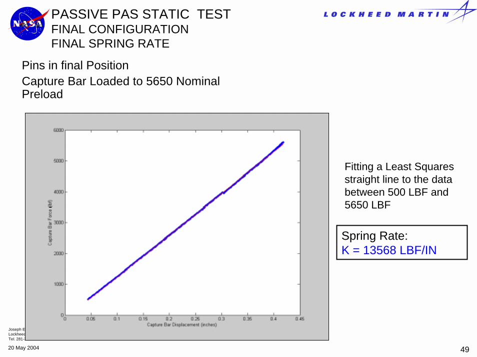
Pins in final PositionCapture Bar Loaded to 5650 Nominal Preload
Fitting a Least Squares straight line to the data between 500 LBF and 5650 LBF
Spring Rate: K = 13568 LBF/IN

Joseph E. KastelicLockheed Martin Space OperationsTel. 281-333-7352
5020 May 2004
AMS PAS Interface Verification Test (IVT)
Description: In March of 2003 the AMS Passive PAS was fitted to the S3 Zenith Inboard PAS 2 site in the Space Station Processing Facility High Bay at Kennedy Space Center for a flight to flight evaluation of the Preload and Release Mechanism.
Though not an official verification the test did validate the design concept and the considerable effort in developing the Interface Requirements specified in SSP 57003, SSP 57004 and SSP 42131.
Test Procedure Summary:• The AMS Passive PAS was hoisted to the Upper Inboard PAS number 2 CAS
site.• The PAS 2 Capture Claw was closed on the AMS PAS Capture Bar.• The preload at full closure was measured• The proximity of the PAS Capture Bar Mounting hardware to the EBCS
Target Assembly was measured at Loaded Condition.• The AMS Passive PAS Release Mechanism was used to unload the Capture
Claw Preload. Proximity to Target was measured in Unloaded Condition• The Capture Bar was removed demonstrating the required contingency
capability to unload and remove the payload.

Joseph E. KastelicLockheed Martin Space OperationsTel. 281-333-7352
5120 May 2004
Turnbuckles
Cables
Hoist Rings
USS Simulator
AMS-02PAS
AMS IVTPAS CONFIGURATION
USS Simulator: Used to simulate the effect on Spring Rate of the AMS Lower USS structure

Joseph E. KastelicLockheed Martin Space OperationsTel. 281-333-7352
5220 May 2004
AMS IVTCAPTURE CLAW PRELOADS THE CAPTURE BAR

Joseph E. KastelicLockheed Martin Space OperationsTel. 281-333-7352
5320 May 2004
AMS IVTCAPTURE CLAW PRELOADS THE CAPTURE BAR

Joseph E. KastelicLockheed Martin Space OperationsTel. 281-333-7352
5420 May 2004
AMS IVTCAPTURE CLAW PRELOADS THE CAPTURE BAR
FULLYLATCHED
.665"*
Predicted Preload: 5650 LBFActual Preload per TPS BCP-S3-T037 Cycle 1: 5470 Cycle 2: 5472

Joseph E. KastelicLockheed Martin Space OperationsTel. 281-333-7352
5520 May 2004
AMS IVTPROXIMITY TO TARGET
View Along Y-axis (PAS coordinate System)
GAP
Preloaded ConditionActual Gap per TPS BCP-S3-T037Actual: .325Minimum Allowed Per SSP 57003 AP Envelope: .250
Unloaded ConditionActual Gap per TPS BCP-S3-T037Actual: .209Minimum Allowed Per SSP 57003 AP Envelope: .200

Joseph E. KastelicLockheed Martin Space OperationsTel. 281-333-7352
5620 May 2004
AMS IVTUnloading and Removing the Capture Bar
Requirements• To Relieve the Capture Bar Preload Completely.
• SSP 57003 requires a minimum unload stroke of .71 inches
• To remove the Capture Bar from the Capture Claw
Results of Load Removal TestThe AMS Capture Bar was Lowered .71 inches as required using the AMS PAS Load release Mechanism Assembly. A visible gap of .033 was measured guaranteeing a Zero Preload
The Capture Bar was retracted Completely through the CLA and The payload was hoisted off of the S3 Truss.
Capture Bar lowered and retracted axially through the Bearing Assembly

Joseph E. KastelicLockheed Martin Space OperationsTel. 281-333-7352
5720 May 2004
AMS IVTCONCLUSIONS
Preload was shown to be within 3.2 percent of the nominal load value defined in SSP 57003 Section 3.1.3.1.3.1
Nominal Preload expected 5650 lb: Actual 5470 lb
Capture Bar was Unloaded and removed from the CLA
The preload was removed with a .71 inch stroke as specified in SSP 57003 Section 3.1.3.2.1 A visible Gap was measured
The Loaded Capture Bar Proximity to BCS Target was within the AP envelope defined in SSP 57003 Section 3.1.3.1.1.1
The Unloaded Proximity to the BCS Target was within AP Envelope Limits described in SSP 57003 Section 3.1.3.1.1.1

Joseph E. KastelicLockheed Martin Space OperationsTel. 281-333-7352
5820 May 2004
AMS Passive PAS As Built Dimensions

Joseph E. KastelicLockheed Martin Space OperationsTel. 281-333-7352
5920 May 2004
AMS Passive PAS As Built Dimensions

Joseph E. KastelicLockheed Martin Space OperationsTel. 281-333-7352
6020 May 2004
AMS Passive PAS As Built Dimensions

Joseph E. KastelicLockheed Martin Space OperationsTel. 281-333-7352
6120 May 2004
AMS Passive PAS As Built Dimensions

Joseph E. KastelicLockheed Martin Space OperationsTel. 281-333-7352
6220 May 2004
AMS Passive PAS As Built Dimensions