ampere class linacs: status report on the bnl...
TRANSCRIPT

Ampere Class Linacs: Status Report on the
BNL Cryomodule ?
R. Calaga, I. Ben-Zvi, J. Brennan, R. Bowmann
A. Burrill, X. Chang, P. Cameron, G. CitverD. Gassner, H. Hahn, M. Harrison, A. Hershcovitch
A. Jain, V. Litvinenko, G. McIntyre, C. MontagA. Nicoletti, D. Kayran, A. Fedotov, J. Kewisch
W. Mackay, G. McIntyre, D. Pate, S. PeggsJ. Rank, T. Roser, J. Scaduto, T. Rao
D. Trbojevic, A. Zaltsman, K. C. Wu Y. Zhao
Brookhaven National Laboratory, Upton, NY 11973, USA
H. Bluem, A. Burger, M. Cole, A. Favale
D. Holmes, J. Rathke, T. Schultheiss, A. Todd
Advanced Energy Systems, USA
Abstract
A five-cell high current superconducting cavity for the electron cooling project atRHIC has been designed. The 703.75 MHz cavity and cryomodule is under fabrica-tion and nearing completion. The different components of the cryomodule and thestatus of their fabrication is discussed.
Key words: high current, superconducting, energy recovery, cavitiesPACS: 41.75.Ht
1 Introduction
Electron cooling is a key component in RHIC II, the next luminosity up-grade to combat intrabeam scattering of ions. Cooling gold beams at 100
? Work performed under the auspices of the U.S. Department of Energy.Email address: [email protected] (R. Calaga).
Preprint submitted to Elsevier Science 29 July 2005

GeV/nucleon require an electron beam energy of 54 MeV and a very high av-erage current of about 200 mA. Future projects such as eRHIC (electron-ioncollider) push the operational current to ∼ 500 mA at 20 nC bunch charge orhigher. A five-cell superconducting cavity and cryomodule as shown in Fig. 1is under fabrication as a fundamental unit for the linac structure to acceleratethe electron beam from 2.5 MeV to 54 MeV [1].
Fig. 1. Cut away view of cryomodule and its components
A prototype energy recovery linac (ERL) is under construction at the RHICfacility as a first step towards an ampere class electron cooler. The ERL willact as a test bench to investigate the feasibility of accelerating high currentbeams and study several beam stability issues in this regime in an energyrecovery mode. The ERL will consist of a 703.75 MHz, 2 MeV SRF gun [2] asan injector to the five-cell linac cavity which will accelerate the beam to about20 MeV. The beam will pass through a recirculating ring and back into thecavity at 180 out of phase to recover the energy and will be extracted intothe beam dump. Fig. 2 shows a 3D engineering graphic of the ERL facility inBldg. 912 at Brookhaven National Lab (BNL). The 50 KW transmitter is inplace and work is ongoing on the shielding, interlocks, cryogenics, a.c. powerand other engineering aspects of the project. Fig. 3 shows the proposed layoutof injector, linac and recirculating ring for the prototype ERL.
2

Fig. 2. 3D engineering drawing of ERL facility at BNL including the ERL, controlroom, power sources, cooling dewars, shielding and other equipement.
Fig. 3. Layout of the proposed prototype ERL which includes the SRF gun, linaccavity, recirculating linac and the beam dump.
2 Cavity
The cavity design is greatly influenced by the operational mode of the linac.Several factors influenced the key parameters of the linac cavity includingsynchronization with RHIC frequency, higher order mode (HOM) damping,and availability of high power RF sources which are decribed in detail inRef. [1,3]. The final design of the optimized linac cavity along with the fieldflatness is shown in Fig. 4. Table 1 shows the RF parameters of the proposedERL cavity for the electron cooling project.
3

Table 1Cavity Parameters
Frequency 703.75 [MHz]
RHIC Harmonic 25
Number of cells 5
Active cavity length 1.52 [m]
Iris Diameter 17 [cm]
Beam Pipe Diameter 24 [cm]
G (Ω) 225
R/Q 403.5 [Ω]
Q BCS @ 2K 4.5 × 10¹⁰
Qext 3 × 10⁷
Ep/Ea 1.97
Hp/Ea 5.78 [mT/MV/m]
cell to cell coupling 3%
Sensitivity Factor (N2
β) 833
Field Flatness 96.5 %
Lorentz Detuning Coeff 1.2 [Hz/(MV/m)2]
Lowest Mech. Resonance 96 [Hz]
k|| (σz − 1cm) 1.1 [V/pC]
k⊥ (σz − 1cm) 3.1 [V/pC/m]
HOM Power (10-20 nC) 0.5-2.3 [kW]
3 Copper Prototypes and Testing
Copper (Cu) prototypes play an important role in the investigation of manyRF characteristics of SRF cavities. Although, numerical codes have becomemore accurate and fast in calculating electromagnetic fields, HOM dampingwith complicating 3D geometries and lossy ferrite materials is still a chal-lenge. Therefore, it becomes imperative to benchmark the simulation resultswith prototypes for new designs of SRF cavities. They also provide critical en-gineering experience in manufacturing complicated elliptical structures withstrict tolerences. Two copper prototypes were built for testing purposes andresults of HOM damping issues are discussed in detail in Refs. [4]. Fig. 5 showsthe Cu prototype on a tuning device for frequency and field flatness as wellas a beadpull setup to measure field profiles and HOMs.
4

0
0.2
0.4
0.6
0.8
1
0.2 0.4 0.6 0.8 1 1.2 1.4 1.6 1.8
|E| [
MV
/m]
z [m]
SuperfishMeas
Fig. 4. Graphic of the five-cell cavity and field flatness of the fundamental modefrom simulation and a measurement from the copper prototype.
Fig. 5. Copper prototype tuning fixture (AES) and beadpull setup for field profileand HOM measurements. Measured field flatness 97 ± 0.5 %
Two Cu prototypes were built to test a future possibility of integrating theminto a superstructure (weakly coupled) to improve the “real-estate” gradientwhile maintaining the HOM damping comparable to the single cavity. Thesuperstructure also allows the possibility of integrating two cavities in a singlecryostat driven by a single power coupler. The transition between the twocavities is under design and the testing will be performed soon. Fig 6 showsthe test setup for the measurments.
4 Niobium Fabrication
The Niobium fabrication and tuning of the half cells dumbells were completedin Feburary of 2005. The dumbells and engroups are show in Fig. 4. The
5

Fig. 6. Superstructure setup to measure field profiles and HOM damping.
electron beam welding of the five-cells and the end groups have also beencompleted in May 2005 and the final cavity is being prepared for tuning asshown in Fig. 8. The cavity will be tuned to achieve a good field flatness (>96 %) across the five cells. An initial target frequency has been calculatedfor the warm Nb cavity which after chemical treatment, cryostat assemblywith all mechanical loads and cooling to 2 K will bring the cavity close to theoperating frequency of 703.75 MHz.
Fig. 7. Nb half cells and engroups.
5 Fundamental Power Coupler
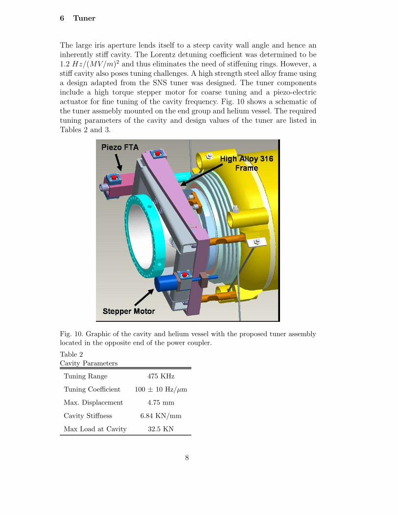
Due to proximity of the frequency to the SNS cavity (805 MHz), a designchoice to adapt the SNS coaxial power coupler to 703.75 MHz was made.The coax-to-waveguide transition assembly was modified to match to 703.75MHz. Fig. 9 shows a schematic of the fundamental power coupler (FPC) andits corresponding components. The processing of the FPC is anticipated to
6
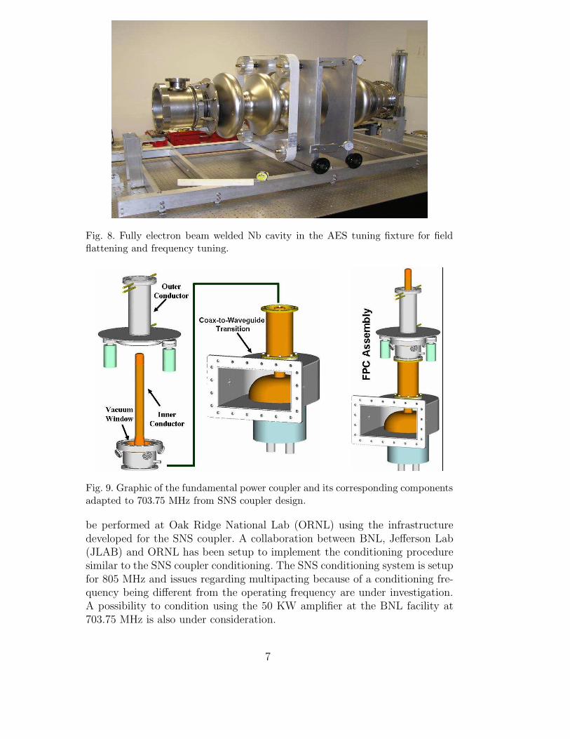
Fig. 8. Fully electron beam welded Nb cavity in the AES tuning fixture for fieldflattening and frequency tuning.
Fig. 9. Graphic of the fundamental power coupler and its corresponding componentsadapted to 703.75 MHz from SNS coupler design.
be performed at Oak Ridge National Lab (ORNL) using the infrastructuredeveloped for the SNS coupler. A collaboration between BNL, Jefferson Lab(JLAB) and ORNL has been setup to implement the conditioning proceduresimilar to the SNS coupler conditioning. The SNS conditioning system is setupfor 805 MHz and issues regarding multipacting because of a conditioning fre-quency being different from the operating frequency are under investigation.A possibility to condition using the 50 KW amplifier at the BNL facility at703.75 MHz is also under consideration.
7
6 Tuner
The large iris aperture lends itself to a steep cavity wall angle and hence aninherently stiff cavity. The Lorentz detuning coefficient was determined to be1.2 Hz/(MV/m)2 and thus eliminates the need of stiffening rings. However, astiff cavity also poses tuning challenges. A high strength steel alloy frame usinga design adapted from the SNS tuner was designed. The tuner componentsinclude a high torque stepper motor for coarse tuning and a piezo-electricactuator for fine tuning of the cavity frequency. Fig. 10 shows a schematic ofthe tuner assmebly mounted on the end group and helium vessel. The requiredtuning parameters of the cavity and design values of the tuner are listed inTables 2 and 3.
Fig. 10. Graphic of the cavity and helium vessel with the proposed tuner assemblylocated in the opposite end of the power coupler.
Table 2Cavity Parameters
Tuning Range 475 KHz
Tuning Coefficient 100 ± 10 Hz/µm
Max. Displacement 4.75 mm
Cavity Stiffness 6.84 KN/mm
Max Load at Cavity 32.5 KN
8

Table 3Cavity Parameters
Frequency Range 475 KHz 2 KHz
Resolution 1 KHz 25 Hz
Speed 1 sec/KHz < 10 µs/Hz
Duty < 8 /day cw
7 Buffer Chemical Processing
The buffer chemical treament (BCP) of the cavity is planned to be performedat the SRF facility at JLAB. The complete procedure of the BCP has beenidentified and discussed in detail in Ref. [6]. The procedure will include aninitial heavy etching of 200 µm of the Niobium (Nb) surface followed by bakingin vacuum and RF testing at 300 K and 2 K. A light BCP may be performedif the Q0 and accelerating gradient are not satisfactory. A high pressure waterrinse will be performed before the welding and assembly of He vessel andother components. A special system is under fabrication at BNL due to theincompatibility of the cavity in the JLAB water rinse cabinet. Engineeringefforts are nearing completion to provide any tooling and equipment that arerequired specifically for the five-cell cavity to adapt with the exisiting JLABinfrastructure.
8 Ferrite Absorbers
Ferrite absorbers were determined to be the most efficient HOM dampingscheme for the five-cell cavity. The absorbers are attached to the beam pipeat 24 cm diameter in the warm section and are water cooled. These absorbershave been directly incorporated from a Cornell design used in storage rings [5].Prototype absorbers shown in Fig. 11 were constructed to test HOM dampingon the Cu prototype and the measurements confirm the damping of HOMs aspredicted by simulations [4]. The actual absorbers have been manufactured byACCEL and assembled in class 100 clean room. Fig. 12 shows the absorbersbeing prepared to be shipped to JLAB for final assembly after cavity BCP.
9 Low Level RF
As a long term goal, a new fully digital low-level RF (LLRF) system is wellunderway. The goal of this digital system will be to integrate the LLRF for
9

Fig. 11. Prototype ferrite absorbers for HOM damping measurements on the coppermodel.
Fig. 12. Ferrite absorbers to be used for broad band HOM damping.
all the machines at the RHIC accelerator complex. This will include RHIC,AGS, Booster, electron cooler and EBIS (source). The proposed system willbe phase locked to the RHIC master oscillator. The system is based on digitalIQ fast-feedback for RF amplitude and phase control. The stability targets forthe ERL cavity and gun are < 10−4 in amplitude and < 0.1 in phase. Theelectronics are based on a generic carrier platform with “PowerPC” embeddedFEC running VxWorks. The XMC daughter sites for daughter modules (DSP& FPGA signal processing, DAC/DDS, ADC, etc..) implement all controlfunctionalities. A preliminary system based on the SNS RF system adaptedto 703.75 MHz is already in place for the cavity testing and as a backup control
10

system is shown in Fig. 13 [7].
Fig. 13. Block diagram of the LLRF system adapted from SNS RF system to 703.75MHz.
10 Cryomodule Assembly
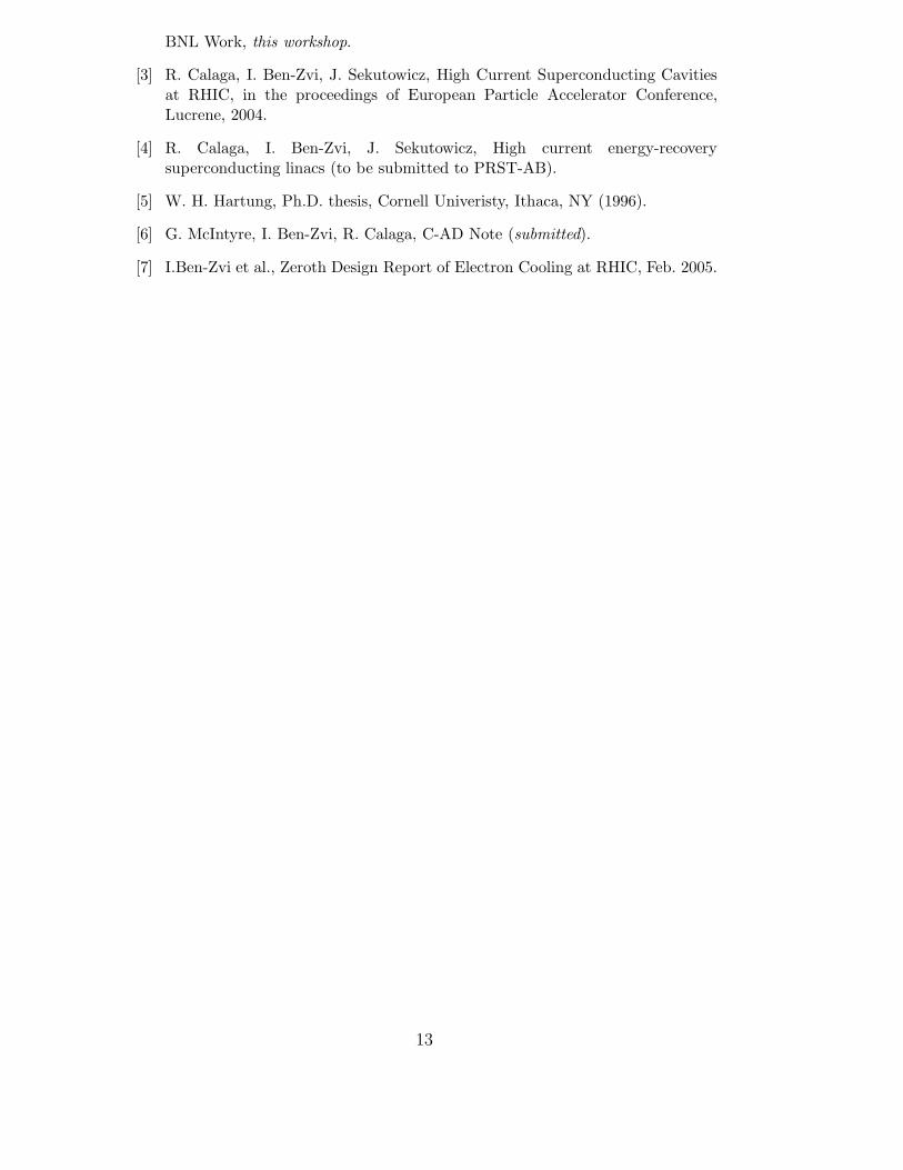
Since, the chemical treatment of the cavity is set to take place in JLAB, theassembly of the cryostat is split into two phases. The clean cavity along withthe end groups, power coupler, ferrite absorbers, and the gate valves will beassembled in a class 100 clean room at JLAB as shown in Fig. 14. The cavitystring attached to the space frame will be transported to BNL to finish thefinal assembly of the cyrostat components in the beam line. Fig. 15 shows anengineering drawing of the five-cell cavity and cryostat as installed.
11 Summary
A high current superconducting five-cell cavity in an energy-recovery modewas proposed for the electron cooling project at RHIC. The fabrication of the
11
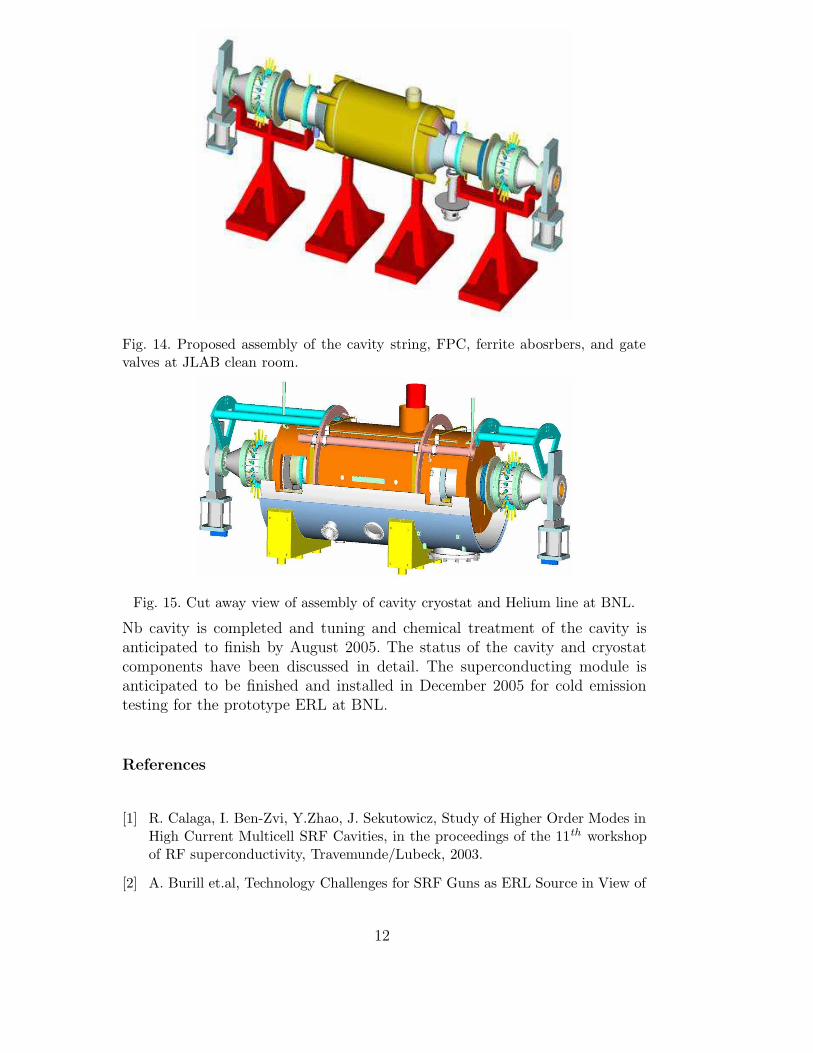
Fig. 14. Proposed assembly of the cavity string, FPC, ferrite abosrbers, and gatevalves at JLAB clean room.
Fig. 15. Cut away view of assembly of cavity cryostat and Helium line at BNL.
Nb cavity is completed and tuning and chemical treatment of the cavity isanticipated to finish by August 2005. The status of the cavity and cryostatcomponents have been discussed in detail. The superconducting module isanticipated to be finished and installed in December 2005 for cold emissiontesting for the prototype ERL at BNL.
References
[1] R. Calaga, I. Ben-Zvi, Y.Zhao, J. Sekutowicz, Study of Higher Order Modes inHigh Current Multicell SRF Cavities, in the proceedings of the 11th workshopof RF superconductivity, Travemunde/Lubeck, 2003.
[2] A. Burill et.al, Technology Challenges for SRF Guns as ERL Source in View of
12
BNL Work, this workshop.
[3] R. Calaga, I. Ben-Zvi, J. Sekutowicz, High Current Superconducting Cavitiesat RHIC, in the proceedings of European Particle Accelerator Conference,Lucrene, 2004.
[4] R. Calaga, I. Ben-Zvi, J. Sekutowicz, High current energy-recoverysuperconducting linacs (to be submitted to PRST-AB).
[5] W. H. Hartung, Ph.D. thesis, Cornell Univeristy, Ithaca, NY (1996).
[6] G. McIntyre, I. Ben-Zvi, R. Calaga, C-AD Note (submitted).
[7] I.Ben-Zvi et al., Zeroth Design Report of Electron Cooling at RHIC, Feb. 2005.
13