ammonia machinery room ventilation - iiar org ... bulletins/discontinued... · ence only many of...
TRANSCRIPT
For h
istor
ical r
efer
ence
onl
y
Bulletin No. 111 06/02
Guidelines for:
Ammonia MachineryRoom Ventilation
International Institute ofAmmonia Refrigeration
For h
istor
ical r
efer
ence
onl
yNOTICE
The information contained in these guidelines has been obtained from sources believed to be reliable. However, itshould not be assumed that all acceptable methods or procedures are contained in this document, or that additional measures may not be required under certain circumstances or conditions. The International Institute of AmmoniaRefrigeration makes no warranty or representation, and assumes no liability or responsibility, in connection with anyinformation contained in this document.
The Institute recommends use of and reference to this document by private industry, government agencies, andothers. Compliance with this publication is intended to be voluntary and not mandatory. The Institute does not“approve” or “endorse” any products, services or methods. This document should not be used or referenced in anyway which would imply such approval or endorsement.
Note that the various building codes and regulations referenced in this document may be amended from time to timeand it should not be assumed that the versions referenced herein are the most current versions of such codes andregulations. Please consult the appropriate regulatory authorities for the most up to date versions.
© Copyright 2002. International Institute of Ammonia Refrigeration. All Rights Reserved.
For h
istor
ical r
efer
ence
onl
yTable of Contents
1 INTRODUCTION . . . . . . . . . . . . . . . . . . . . . . . . . . . . . . . 1
1.1 Rationale for Mechanical Ventilation . . . . . . . . . . . 11.2 Codes & Standards . . . . . . . . . . . . . . . . . . . . . . . . 11.3 Flammability Issues. . . . . . . . . . . . . . . . . . . . . . . . 31.4 Leak Scenarios . . . . . . . . . . . . . . . . . . . . . . . . . . . 4
1.4.1 Vapor Leaks . . . . . . . . . . . . . . . . . . . . . . . . . . . . 41.4.2 Liquid Leaks . . . . . . . . . . . . . . . . . . . . . . . . . . . . 4
2 SCOPE . . . . . . . . . . . . . . . . . . . . . . . . . . . . . . . . . . . . . . . 5
3 VENTILATION DESIGN CONSIDERATIONS . . . . . . . . . 5
3.1 Base Case – Applicable Code . . . . . . . . . . . . . . . 63.2 Determine Code-Compliant
Ventilation Rates . . . . . . . . . . . . . . . . . . . . . . . . . . 63.2.1 Emergency Ventilation Rate . . . . . . . . . . . . . . . . 63.2.2 Non-Emergency Intermittent Ventilation Rate. . . 83.2.3 Non-Emergency Continuous Ventilation Rate . . 9
3.3 Ventilation Fan Selection & Layout . . . . . . . . . . . 103.3.1 Fan Type . . . . . . . . . . . . . . . . . . . . . . . . . . . . . . 103.3.2 Intake Type . . . . . . . . . . . . . . . . . . . . . . . . . . . . 103.3.3 Intake and Exhaust Locations . . . . . . . . . . . . . 11
3.4 Ammonia Detectors. . . . . . . . . . . . . . . . . . . . . . . 113.4.1 Selection . . . . . . . . . . . . . . . . . . . . . . . . . . . . . . 113.4.2 Location . . . . . . . . . . . . . . . . . . . . . . . . . . . . . . 11
3.5 Controls . . . . . . . . . . . . . . . . . . . . . . . . . . . . . . . . 123.5.1 Machinery Room Ventilation . . . . . . . . . . . . . . . 123.5.2 Emergency Shutdown. . . . . . . . . . . . . . . . . . . . 123.5.3 Alarms. . . . . . . . . . . . . . . . . . . . . . . . . . . . . . . . 133.5.4 Codes & Standards . . . . . . . . . . . . . . . . . . . . . 13
4 OPERATION & MAINTENANCE . . . . . . . . . . . . . . . . . . 14
4.1 Ventilation Fans and Air Intakes . . . . . . . . . . . . . 144.2 Machinery Room Pressure Relationships . . . . . . 154.3 Ammonia Detectors. . . . . . . . . . . . . . . . . . . . . . . 154.4 Controls . . . . . . . . . . . . . . . . . . . . . . . . . . . . . . . . 15
5 VENTILATION DESIGN EXAMPLE. . . . . . . . . . . . . . . . 16
5.1 Machinery Room Specifications . . . . . . . . . . . . . 165.2 Design Procedure . . . . . . . . . . . . . . . . . . . . . . . . 16
6 REFERENCES . . . . . . . . . . . . . . . . . . . . . . . . . . . . . . . . 22
APPENDIX A: MACHINERY ROOM HEAT LOAD CALCULATIONS . . . . . . . . . . . . . . . . . . . 23
Bulletin No. 111 06/02

For h
istor
ical r
efer
ence
onl
y
1
1 INTRODUCTION
This bulletin provides guidelines for the design and operation of mechanical ventilationsystems for ammonia machinery rooms. The bulletin includes: a discussion of the roleof mechanical ventilation in controlling ammonia concentrations during leaks; a reviewof relevant national and international codes; ventilation design considerations; and adiscussion of recommended ventilation system operation & maintenance practices.
1.1 Rationale for Mechanical Ventilation
Ventilation for ammonia machinery rooms serves multiple purposes:
1. To purge ammonia vapor from the machinery room in emergency situations to help prevent the concentration of ammonia from reaching the lower flammability limit; thereby, minimizing the possibility of a deflagration occurring in the machinery room.
2. To prevent excessive temperature rise (or limit temperature) in the machineryroom during normal operation due to equipment-generated heat.
3. To provide fresh air for machinery room occupants.
4. To maintain the machinery room under negative pressure.
5. To enhance ammonia detector responsiveness.
The function of machinery room ventilation can be categorized into either emergencyor non-emergency ventilation. The first item above falls into the category of “emergencyventilation” and the remaining four items fall into the category of “non-emergency”ventilation. All are important for safe ammonia machinery room operation.
1.2 Codes & Standards
Several national and international codes and standards specify requirements formachinery room ventilation systems, ventilation rates, and associated controls. The following list encompasses the codes and standards most widely used in establishingminimum requirements for machinery room mechanical ventilation systems.
• ANSI/IIAR 2 – 1999: Equipment, Design, and Installation of AmmoniaMechanical Refrigerating Systems (IIAR 2)
• ANSI/ASHRAE 15 – 2001: Safety Standard for Refrigeration Systems(ASHRAE-15)
• ISO 5149 – 1993: Mechanical Refrigerating Systems Used for Cooling and Heating-Safety Requirement (ISO-5149)
• ICBO – 1997: Uniform Mechanical Code (UMC)
• BOCA – 1993: The National Mechanical Code (NMC)
• ICC – 2000: International Mechanical Code (IMC)
• SBCCI – 1997: Standard Mechanical Code (SMC)

For h
istor
ical r
efer
ence
onl
yTable 1 summarizes the emergency and non-emergency ventilation rate requirementsfrom each of the above-mentioned codes and standards.
Table 1: Summary of ventilation rate requirements
Emergency Ventilation Non-Emergency Ventilation
Source Rate Minimum Rate Minimum
G100 a, cfm ∆T c < 18°F 0.5 cfm/ft2
ANSI/IIAR 2 – 1999SIG70 a [l/s]
12 ACHb
∆T c < 10°C 2.54 l/s per m2
G100 a, cfm ∆T c < 18°F0.5 cfm/ft2 f
or20 cfm per person fANSI/ASHRAE 15 – 2001
SIG70 a [l/s]
N/Ah
∆T c < 10°C 2.54 l/s per m2 f
or9.44 l/s per person f
3/236.17 G a,d cfmISO: 5149 – 1993 g 3/288.13 SIG a,d [l/s] N/Ah No distinction
G100 a, cfm T e < 104°F 0.5 cfm/ft2ICBO: Uniform MechanicalCode – 1997
SIG70 a [l/s]N/Ah
T e < 40°C 2.54 l/s per m2
G100 a, cfm ∆T c < 18°F
0.5 cfm/ft2 f
or20 cfm per person f
ICC: International MechanicalCode – 2000
&SBCCI: Standard MechanicalCode – 1997
SIG70 a [l/s]
N/Ah
∆T c < 10°C
2.54 l/s per m2 f
or9.44 l/s per person f
BOCA: National MechanicalCode – 1993 No distinction 6 ACH
a where G is the mass of refrigerant in lb and GSI is the mass of refrigerant in kg
b air changes per hour (ACH) with the corresponding ventilation rate given by Q=V*0.2 (cfm);QSI=VSI/0.3 [l/s]
c temperature difference between machinery room and ambientd requires the continuous operation of the ventilation system at prescribed rate but need not
exceed 15 ACHe temperature in the machinery roomf operated when occupied to supply at least 0.5 cfm/ft2 [2.54 l/s per m2] or 20 cfm per person
[9.44 l/s per person]g ISO 5149 is an international standardh a separate “minimum” emergency ventilation rate is not prescribed
2
For h
istor
ical r
efer
ence
onl
yMany of the codes and standards are neither consistent nor uniform in their approachto rate specification for machinery room ventilation. As a result, it is not possible toconclusively identify one particular code as the “most restrictive” or “least restrictive.”Section 3.2.1 of this bulletin provides further discussion and comparisons among emergency ventilation rate requirements based on the above-referenced codes.
It is essential that designers carefully consider the machinery room ventilationrequirements based on pertinent local codes in force for the machinery room beingdesigned. Designers may wish to compare the ventilation rate requirements based ontheir local code with the rate requirements derived from other codes and standards.In cases where the local code is the least restrictive, designers have the flexibility toincrease ventilation rates to comply with more restrictive codes.
Apart from the codes and standards referenced in Table 1, this bulletin provides recommendations for both emergency and non-emergency ammonia machinery room ventilation rates. Section 3.2.1 provides recommendations for machinery roomemergency ventilation rates and Sections 3.2.2 – 3.2.3 outline recommendations for machinery room non-emergency ventilation rates.
1.3 Flammability Issues
Anhydrous ammonia is flammable in a relatively narrow range. A substance (or mixture) is considered to be flammable if it propagates a flame. The most frequentlyreported range of flammability for ammonia in air is 16%1 – 25%2 (by volume). Anumber of factors influence the flammability of an ammonia-air mixture includingpressure, temperature, mixture turbulence intensity, ignition source strength, and thepresence of water vapor or other constituents such as oil. For additional information on ammonia flammability, see Fenton, et al. (1995) and Khan, et al. (1995).
An important characteristic of flammable mixtures is the flame speed. The flame speedof a combustible mixture may be subsonic or supersonic. The propagation of a flamefront at subsonic speeds will result in a deflagration. A characteristic of a deflagration isthat the overpressure created by the event is relatively low (i.e. the ratio of final to initialpressure is only slightly greater than one). Although the overpressure generated by adeflagration is low, deflagrations can damage building structures and equipment. Incontrast, a detonation occurs when the flame speed propagation is supersonic.Detonations can lead to considerable overpressures (i.e. pressure ratios on the orderof 40 are possible from detonation events, Fenton, et al. 1995). The overpressures generated by detonations can have devastating impacts on building structures andequipment. Deflagration events exhibit a significantly lower energy level (i.e. they arenot prone to result in overpressure situations) upon ignition of the flammable mixture.Ignition of ammonia-air mixtures do not result in supersonic flame speeds that lead todetonation events.
1 16% is commonly referred to as the lower flammability limit or LFL.2 25% is commonly referred to as the upper flammability limit or UFL.
3

For h
istor
ical r
efer
ence
onl
y1.4 Leak Scenarios
In an uncontrolled release of ammonia during an emergency situation, theconcentration of ammonia in a machinery room is highly dynamic. The machinery roomammonia concentration at any instant in time will depend on the rate of ammonia vaporproduction and the rate of ammonia dilution with fresh outside air. Under emergencyconditions, the goal of a mechanical ventilation system is to dilute ammonia vapor inthe machinery room sufficiently to prevent the concentration from reaching the lower flammability limit (LFL).
Under a leak scenario, ammonia vapor can be generated by three distinct sources.The first source is a leak originating from a vapor source. In this case, the rate of vaporproduction is equal to the vapor leak rate. The second source of vapor generation is byevaporation of liquid ammonia outside of the system. Three modes of heat transfercombine to influence the rate of ammonia evaporation — conduction, convection, andradiation. Liquid ammonia that contacts any surface warmer than -28°F [-33°C]3 willresult in evaporation by a combination of conduction and convection heat transfer.Convection of heat from the machinery room air itself will also contribute to ammoniaevaporation. Finally, radiation of heat from surfaces in the machinery room warmerthan -28°F [-33°C]3 will contribute to the evaporation of liquid ammonia. The thirdsource of vapor generation is from flash gas. Flash gas will be generated whenever a leak originates from a liquid refrigerant source at pressures higher than atmosphericand temperatures warmer than -28°F [-33°C]3.
1.4.1 Vapor Leaks
Any part of a system that operates above atmospheric pressure is at risk forleaking refrigerant to ambient. Vapor leaks can occur in high-side components(piping, valves, compressors, flanges, etc.) and low-side components operatingabove atmospheric pressure.
1.4.2 Liquid Leaks
When liquid ammonia leaks from a system, vapor will be generated by evaporationand/or flash gas. Because ammonia has a high latent heat of vaporization, the rate of ammonia vapor produced by evaporation from a heat source is relatively small(~0.5 cfm per 1,000 Btu/hr [0.81 l/s per kWT] of heat transferred to the liquid).In a liquid leak scenario, the rate of ammonia vapor production by evaporation is high initially due to the high heat transfer rate between the cold liquid and warmersurfaces it thermally contacts. As the surrounding surfaces give up their heat to theliquid, the rate of vapor production by evaporation progressively decreases.
In contrast to ammonia vapor generation by evaporation, the rate of vapor production from flash gas can be substantial when a leak originates from a highpressure liquid source. If liquid at a pressure above atmospheric and a temperature
3 The boiling point for anhydrous ammonia at sea level pressure is -28°F [-33°C]. For elevationsother than sea level, the corresponding boiling point will differ.
4

For h
istor
ical r
efer
ence
onl
ywarmer than the saturation temperature corresponding to the local atmosphericpressure leaks, flash gas will form downstream of the leak. The proportion of sourceliquid that flashes to vapor is dependent on the pressure and temperature of thesource liquid. Figure 1 shows the rate of flash gas produced from a 1 lb/min [0.45 kg/min] leak of high pressure liquid over a range of upstream liquid pressureswith varying degrees of liquid subcooling.
Figure 1: Flash gas vapor generation rate for a 1 lb/min [0.45 kg/min] leak rate
2 SCOPE
The scope of this bulletin is to provide guidelines for the design and operation ofmechanical ventilation systems serving ammonia machinery rooms. It is not intendedfor any other purpose or application of ammonia.
3 VENTILATION DESIGN CONSIDERATIONS
For a machinery room to be considered a “Non-Hazardous (unclassified) Location,”as defined by ASHRAE-15, it requires emergency ventilation. In situations where amechanical ventilation system is not provided in accordance with ASHRAE-15, themachinery room would be considered a Class I, Division 2 location. In this case, allelectrical equipment in the room would be designed to conform to the requirements for a Class I, Division 2, Group D location, per the governing edition of the NationalElectric Code.
5
Fla
sh G
as P
rod
uct
ion
(ft
3 /min
)
Atm
osp
her
ic P
ress
ure
Lim
it
Source Liquid Pressure (psia)
For h
istor
ical r
efer
ence
onl
y3.1 Base Case — Applicable Code
The first step in the process of designing a machinery room ventilation system is todetermine the code(s) that are applicable for the facility in question. One should keepin mind that codes represent minimum requirements. It is acceptable to design asystem with ventilation rates that exceed the minimum requirements established by the prevailing code.
In addition to designing the machinery room ventilation system to be code-compliant, it is advisable to consult with the insurance underwriter for the facility to determine if they have requirements that may be more stringent or extend beyond the applicablecode. For example, an underwriter may have specific requirements involving damage-limiting construction. For additional guidance on damage-limiting construction,see IIAR Bulletin 112.
3.2 Determine Code-Compliant Ventilation Rates
Machinery room ventilation rates can be separated into two categories: emergencyand non-emergency. Emergency ventilation is required to purge ammonia vapor from the machinery room in the event of a leak in an effort to prevent the machineryroom concentration of ammonia from reaching the lower flammability limit. The “non-emergency” ventilation category can be further sub-divided into “intermittent”and “continuous” modes. Non-emergency machinery room ventilation is required for several purposes. Table 2 summarizes the function of emergency and non-emergency ventilation modes.
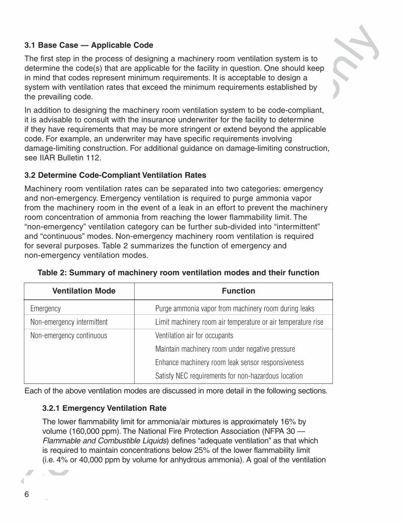
Table 2: Summary of machinery room ventilation modes and their function
Each of the above ventilation modes are discussed in more detail in the following sections.
3.2.1 Emergency Ventilation Rate
The lower flammability limit for ammonia/air mixtures is approximately 16% byvolume (160,000 ppm). The National Fire Protection Association (NFPA 30 —Flammable and Combustible Liquids) defines “adequate ventilation” as that which is required to maintain concentrations below 25% of the lower flammability limit (i.e. 4% or 40,000 ppm by volume for anhydrous ammonia). A goal of the ventilation
Ventilation Mode Function
Emergency Purge ammonia vapor from machinery room during leaks
Non-emergency intermittent Limit machinery room air temperature or air temperature rise
Non-emergency continuous Ventilation air for occupants
Maintain machinery room under negative pressure
Enhance machinery room leak sensor responsiveness
Satisfy NEC requirements for non-hazardous location
6

For h
istor
ical r
efer
ence
onl
ysystem design and operation under emergency conditions is to purge ammoniavapors in an attempt to maintain ammonia concentrations below 4% by volume in theevent of a refrigerant leak.
A simple rule is to recognize that at least 24 volumes of fresh outside air need tobe mixed with each volume of ammonia vapor released into the machinery roomto keep the machinery room concentration of ammonia vapor below 4 percent.In other words, the amount of air-ammonia mixture that needs to be exhaustedfrom a machinery room is 25 times the ammonia vapor generation rate (24 volumes of fresh air plus 1 volume of ammonia vapor).
The emergency ventilation rate will depend on the specific code in force. IIAR 2bases the minimum emergency ventilation rate requirement on (a) the quantityof refrigerant in the largest system or (b) 12 air changes per hour, whicheveris larger:
a.) (cfm)
[l/s]
where,
Q is the ventilation rate (cfm),
QSI is the ventilation rate in SI units [l/s],
G is the mass of refrigerant (lb) in the largest system, any part of which is located in the machinery room, and
GSI is the refrigerant mass in SI units [kg];
or
b.) (cfm)
[l/s]
where,
Q is the ventilation rate (cfm),
QSI is the ventilation rate in SI units [l/s],
V is the room volume (ft3), and
VSI is the room volume in SI units [m3].
ASHRAE-15 and the UMC require the same emergency ventilation rate as IIAR 2with the exception that neither ASHRAE-15 nor the UMC specify a minimumemergency ventilation rate.
Q G= ⋅100
Q GSI SI= ⋅[ ]70
7
QV=5
QV
SISI=
0 3.

For h
istor
ical r
efer
ence
onl
yISO 5149 bases the emergency ventilation rate on the mass of refrigerant in thelargest system; however, the formula (see Table 1) differs from that provided inIIAR 2, ASHRAE-15, and UMC. When the refrigerant inventory is less than 36,532lb [16,572 kg], the ISO 5149 emergency ventilation rate will be less than theemergency ventilation rate prescribed by IIAR 2, ASHRAE-15, and the UMC. Atthis refrigerant inventory, the emergency ventilation rate is 19,114 cfm [9,021 l/s].For systems with refrigerant quantities in excess of 36,532 lb [16,572 kg], the ISO5149 emergency rate will be larger than IIAR 2 and ASHRAE-15. Figure 2 showsthe emergency ventilation rate relationship between these codes.
Figure 2: Emergency ventilation rate comparison
Once the code-prescribed emergency ventilation rate is established, the resultingemergency ventilation rate on a per unit machinery room area (cfm per ft2 or l/s per m2) basis should be calculated. It is recommended that the emergencymachinery room ventilation rate should be at least 10 cfm/ft2 [50.8 l/s per m2]with a minimum rate of 20,000 cfm [9,439 l/s]. In some cases, designing andinstalling a ventilation system to achieve the 10 cfm per ft2 [50.8 l/s per m2] – 20,000 cfm [9,439 l/s] minimum ventilation rate is not practical. In such cases, thedesigner should consider applying the IIAR 2 emergency ventilation rate alternativeof 12 ACH.
3.2.2 Non-Emergency Intermittent Ventilation Rate
Most codes have established a non-emergency ventilation rate requirement toeither limit the machinery room temperature rise or the absolute machinery roomtemperature. This bulletin categorizes such requirements as “non-emergency
System Refrigerant Mass (lb)
8
Em
erg
ency
Ven
tila
tio
n R
ate
(cfm
)
19,114 cfm
36,532 lb
IIAR 2, ASHRAE-15, UMC
ISO 5149

For h
istor
ical r
efer
ence
onl
yintermittent ventilation rates” since operation of the ventilation system in this modeis relatively infrequent and only on an as-needed basis.
Non-emergency intermittent ventilation rates are based on a machinery room heatload calculation. The load calculation needs to consider all sources of heat in amachinery room including:
• electric motors (specifically, heat produced due to the motor inefficiency)
• engine drives (heat loss from engine jackets and manifolds)
• transmission heat gains (envelope heat gains)
Appendix A provides additional information on heat load calculations for machinery rooms.
Once an estimate of the total machinery room heat load is obtained, the requiredventilation rate can be determined by the following:
(cfm)
[l/s]
where,
Qnon-emergency is the peak intermittent ventilation rate (ft3/min) [m3/s] required to limit the machinery room temperature rise,
qtotal is the total machinery room heat load (Btu/hr) [Wt ],
Tsupply is the temperature of air being supplied to the machinery room (usually the outdoor air dry bulb temperature) (°F) [°C], and
TER is the design machinery room temperature (°F) [°C].
In the case of both IIAR 2 and ASHRAE-15, the quantity (Tsupply – TER ) is equal to 18°F [10°C] since the continuous ventilation is designed to maintain a maximumtemperature rise above ambient.
In some cases, the required non-emergency intermittent ventilation rate to limitmachinery room temperature rise may exceed the emergency ventilation rate. Insuch situations, the fans selected for the machinery room ventilation system mustbe sized at the larger rate. In cases where the emergency ventilation rate exceedsthe non-emergency intermittent rate, the emergency ventilation rate operating modecan be used to achieve the non-emergency intermittent machinery room ventilationrate requirement to limit temperature rise. The most convenient approach for implementing the non-emergency intermittent ventilation rate control is by the use of a thermostat which cycles to the higher ventilation rate mode intermittently to maintain the machinery room temperature in the acceptable range.
T Tnon emergency
total
supply ER
− =⋅ −( )1 08.
T Tnon emergency SI
total SI
supply ER
− =⋅ −( )
,,
.1 21
9
For h
istor
ical r
efer
ence
onl
y3.2.3 Non-Emergency Continuous Ventilation Rate
Several codes have also established “minimum” non-emergency ventilationrates. This bulletin categorizes such requirements as “non-emergencycontinuous ventilation rates” since the operation of the ventilation system in thismode is non-stop. Table 2 summarizes the multiple functions that continuousmachinery room ventilation serves.
A minimum non-emergency continuous ventilation rate of 1 – 2 cfm per ft2
[5 – 10 l/s per m2] is recommended to facilitate circulation of outside air throughthe machinery room and to continually maintain the machinery room undernegative pressure. This ventilation rate should be maintained continuously whileequipment in the machinery room is operational.
In some applications, continuously ventilating a machinery room at 1 – 2 cfm/ft2
[5 – 10 l/s per m2] may be impractical due to a number of factors that include:significant auxiliary make-up air heating load during wintertime, machineryroom equipment idle (seasonal operations), and the absence of personnel inthe machinery room. Under such conditions, the non-emergency continuousventilation may be cycled off if the following provisions are satisfied:
1. Controls cycle on the non-emergency continuous ventilation when themachinery room concentration of ammonia reaches 50 ppm.
2. Provisions are in place to energize the ventilation systems to provide non-emergency continuous ventilation rate whenever the machinery room isoccupied. This function can be accomplished by the use of a switch outsidethe machinery room or through other means such as occupancy sensors.
3.3 Ventilation Fan Selection & Layout
There are a number of considerations that arise in selecting fans and intake/exhaustlayouts to ensure good ventilation system performance during both non-emergencyand emergency modes of operation. The first step in the process is to select fan(s) thatcan provide the required ventilation air flow in accordance with the rates determined for emergency, non-emergency intermittent, and non-emergency continuous operation.The second step is to select intake type and the third step is to determine suitableintake and exhaust locations.
3.3.1 Fan Type
Consider specifying upblast, high velocity discharge non-sparking fans since theytend to be effective at dispersing ammonia exhaust vapors more effectively. Thistype of fan employs very high discharge velocities and utilizes an entrainmentnozzle which facilitates dispersion of ammonia into the atmosphere.
A number of options are available to obtain the reduced airflow rates required for continuous ventilation including: partial operation of a multiple fan system,multi-speed fans, or variable frequency drive fans.
10

For h
istor
ical r
efer
ence
onl
yElectrical power for machinery room fans should originate from a source outsidethe machinery room to ensure uninterrupted power during a machinery roomemergency electrical shutdown as discussed in section 3.5.2.
3.3.2 Intake Type
Do not use intake louvers with manual dampers. Consider using dampers of a fail-open power-closed type. In sizing intake louvers, select louvers of sufficientarea to minimize the air pressure drop through the damper. If filters are used,select a low pressure drop type. In the design, specify filter pressure drop limits to guide maintenance practices.
Based on the selected louver type and design face velocity, estimate the pressuredrop across the intake louvers. If filters are used, estimate the pressure dropacross a dirty filter. The fan selection should be sized to deliver the required emergency volume flow rate of air with all sources of external pressure drop(intake louver, dirty filters, etc.) present.
3.3.3 Intake and Exhaust Locations
It is essential to provide adequate openings for inlet air to replace that beingexhausted. The following are recommendations related to intake and exhaustlocations:
1. Openings for inlet air should be positioned to avoid intake of discharged air,i.e. short circuiting.
2. The intake (or supply) air and exhaust air ducts (if any) to/from the machineryroom should not serve any other area of the facility.
3. Provide makeup-air intakes to replace the exhaust air to the machinery roomdirectly from outside the building.
4. Machinery room discharge air should be directed upward to provide goodatmospheric dispersion. Designers should consider the natural air flow aroundthe building, prevailing wind, and any surrounding structures.
5. The location of intake and exhausts in the machinery room should bearranged to provide good scavenging of ventilation air through the room. Thiscan typically be accomplished by evenly spacing intake louvers low on sidewalls coupled with ceiling-mounted exhaust fans set back from the intakes.Intake/exhaust arrangements that contribute to short circuiting intake airdirectly to exhaust need to be avoided. Short circuiting can also occur whenexhausts are located close to large doors.
3.4 Ammonia Detectors
Ammonia detectors are recommended in machinery rooms for personnel and propertyprotection. By continuously sensing the presence of ammonia in the machinery room,alarms or control actions are initiated based on sensed concentrations in accordancewith limits described in Section 3.5. The selection, location, and on-going properoperation of ammonia detectors are an integral part of machinery room safety.
11
For h
istor
ical r
efer
ence
onl
y
4 The IDLH (immediately dangerous to life and health) for anhydrous ammonia is 300 ppm.
3.4.1 Selection
Often, two separate ammonia detectors are required for emergency ventilationcontrol and for machinery room electrical shutdown. A low concentration rangedetector (e.g. 0 – 250 ppm) can provide suitable resolution and accuracy forinitiating emergency ventilation operation. A second high concentration rangedetector (e.g. 0 – 20,000 ppm) serves as an input to initiate machinery roomelectrical shutdown. The control setpoints for each concentration range detectorwill differ. For example, the ventilation control sensor is set to initiate theemergency ventilation mode at a concentration of 150 ppm. The machinery room electrical shutdown control sensor will disconnect electrical power to themachinery room at a pre-determined concentration, e.g. 15,000 ppm.
3.4.2 Location
Strictly speaking, ammonia vapor is colorless and lighter than air. However duringa larger release to the atmosphere, anhydrous ammonia can combine with watervapor in the air and form a visible “white cloud.” In this case, the visible whitecloud will tend to be heavier than air and will “ride close to the ground” in aquiescent environment. For this reason, the refrigerant concentration in eachmachinery room should be monitored at two or more points within the room.At a minimum, at least one detector should be located low in the machinery roomto detect any vapor that would tend to ride close to the ground. Typically, thisdetector(s) will have a low range (0 – 250 ppm) for use in controlling the operationof emergency ventilation and alarms. The other detector(s) should be positionedhigh in the machinery room in a location where the continuous circulation ofventilation air through the machinery room will be drawn over the sensor. Thisdetector will have a higher concentration range (e.g. 0 – 20,000 ppm) to controlelectrical shutdown. The detector(s) should be readily accessible for servicing bymaintenance personnel. Additional detectors can be installed for redundancy.
3.5 Controls
The ammonia detectors provide information that is critical for initiating emergencycontrol responses. Based on signals from the ammonia detectors, controls need toinitiate the appropriate machinery room ventilation mode, machinery room electricalshutdown, and supervisory alarms.
3.5.1 Machinery Room Ventilation
Controls are required to ensure proper ventilation system operation in both non-emergency and emergency modes. The machinery room ventilation systemshould be actuated automatically by vapor detector(s) and also operable manually.Automatic operation should be based on continuous monitoring of ammonia concentration in the machinery room.
The typical recommended actuation level for emergency ventilation is 150 ppm(50% of the IDLH4); however, lower activation levels should be used if required by
12
For h
istor
ical r
efer
ence
onl
ythe jurisdictional authority. A manual on/auto emergency ventilation control switchshould be located outside of each machinery room exit door. The return from theemergency to non-emergency (continuous or intermittent) ventilation mode shouldrequire operator intervention through a manual reset.
3.5.2 Emergency Shutdown
Machinery rooms should be designed with emergency electrical power shutdowncapability. The electrical power shutdown should disconnect power from the entiremachinery room with the exception of ventilation exhaust fans (with non-sparkingtype motors) and any equipment that is Class I, Division 2, Group D compliant.The recommended machinery room concentration to initiate machinery room electrical shutdown is 15,000 ppm. Lower threshold concentrations to initiate electrical shutdown can also be considered. The electrical shutdown concentrationshould not exceed 25% of the LFL (i.e. 40,000 ppm).
Manual break glass switches for emergency electrical power shutdown for themachinery room should be located outside each machinery room exit. Initiation of an electrical power shutdown should activate emergency ventilation fans independent of input from ammonia detectors. Any electrical power shutdownshould require manual reset.
3.5.3 Alarms
Ammonia detectors are needed for both alarm and control functions. Alarmsshould annunciate visual and audible alarms inside the machinery room and outside each entrance to the machinery room. Separate alarms should be providedfor emergency ventilation and emergency shutdown. Any alarm reset should bemanual and be located inside the machinery room. If a detector senses arefrigerant concentration exceeding its preset limit, the device should initiate asupervised alarm so that emergency action can be taken.
In addition to initiating a supervised alarm whenever an emergency ventilationoperating mode is actuated, an alarm should also be triggered whenever the ventilation system operating under non-emergency continuous mode fails so thatcorrective action can be taken. Suitable devices to detect continuous ventilationair flow are pressure differential monitors, ultrasonic monitors, or sail switches.Consideration should also be given to monitoring the operability of the non-emergency intermittent ventilation mode. Including an alarm on high machineryroom air temperature is one approach to warn operators of inadequate (or non-operational) non-emergency intermittent ventilation.
3.5.4 Codes & Standards
A number of codes and standards have established specific prescriptiverequirements for refrigerant detection and control action based on the level ofrefrigerant concentration in the machinery room. Table 3 summarizes the refrigerantdetection and control requirements from widely used codes that govern ammoniamachinery room ventilation.
13

For h
istor
ical r
efer
ence
onl
yTable 3: Machinery room concentration threshold for control responses
a an ammonia machinery room is not required to be Class I, Division 2 in accordance with theNEC, if the machinery room ventilation system runs continuous and failure of the mechanicalventilation system activates an alarm or the machinery room is equipped with a refrigerantdetector set to alarm at 1,000 ppm.
b code requires electrical shutdown at 25% of LFL (40,000 ppm for ammonia)c code requires the lesser of 25% of LFL (40,000 ppm) or 50% of IDLH (150 ppm)d intermittent fan control required to keep concentration below 50% of PELe code requires activation of emergency ventilation at concentration no higher than 25% of LFL
(40,000 ppm) and alarm at 25% of LFLf code requires activation of alarms at the lesser of: 25% of LFL (or 40,000 ppm), 50% of IDLH
(or 150 ppm), or PEL (50 ppm)
4 OPERATION & MAINTENANCE
Having an on-going preventive maintenance program helps assure that the non-emergency ventilation system operating modes are operable at all times and the emergency ventilation will reliably function when the need arises. Procedures andtime schedules should be established for testing of the mechanical ventilation system,the ammonia detectors, and the control system (including alarms).
4.1 Ventilation Fans and Air Intakes
Preventive maintenance on ventilation fans, bearings, fan belts, dampers, and filtersshould be performed in accordance with the manufacturer’s recommendations. In theabsence of a specific schedule of maintenance, it is recommended that the followingsystem checks be performed on a quarterly basis:
a. Stop the non-emergency continuous ventilation fan(s) using the appropriateelectrical disconnect(s). Confirm that the alarm for non-emergency continuousventilation functions properly.
14
Ammonia Concentration
Electrical Emergency Non-EmergencySource Shutdown Ventilation Ventilation Alarm
IIAR 2 – 1999 — 1,000 ppm 400 ppm (max) 1,000 ppm
ASHRAE-15 – 2001 None 1,000 ppma continuous 1,000 ppma
ISO 5149 — 40,000 ppm(max)e — 40,000 ppme
UMC – 1997 40,000 ppmb 150 ppmc 50 ppmd 50 ppmf
IMC – 2000 1,000 ppma continuous 1,000 ppma
SMC – 1997 — 40,000 ppm (max) — 40,000 ppm
NMC – 1993 references ASHRAE-15

For h
istor
ical r
efer
ence
onl
yb. Using ampules or cylinders of pre-mixed anhydrous ammonia test gases,expose each of the ammonia detectors in the machinery room to ammoniaconcentrations above the alarm level. Confirm that individual detector(s), control circuitry, ventilation fans, dampers, and alarms function properly.
c. Visually inspect and clean, as-needed, intake and exhaust louvers, debrisscreens, and filters (if equipped).
d. Check the machinery room pressure relationships in both the non-emergencyand emergency modes of ventilation system operation using the method(s)described in Section 4.2.
4.2 Machinery Room Pressure Relationships
A properly operating machinery room ventilation system will establish a zone ofnegative pressure, with respect to surrounding zones of the plant and outdoors, duringboth non-emergency and emergency modes of operation. The benefit of this negativepressure relationship is that ammonia vapor will not infiltrate into other areas of thefacility in the event of a leak within the machinery room. The pressure relationshipbetween the machinery room and adjacent zones of the facility should be verifiedquarterly with all machinery room doors in their normally closed position.
A negative pressure relationship can be established either qualitatively or quantitatively.Qualitative methods rely on the use of chemical smoke (such as titanium tetrachloride)or other sensitive materials (such as tissue paper) to observe the direction of airflow. Ifthe machinery room is under negative pressure, the direction of airflow will be into themachinery room.
Quantitative methods rely on the use of manometers (either an inclined or digitalmicromanometer). The differential pressure between the machinery room and itssurroundings is measured by sensing the pressure inside the machinery room andoutside the machinery room. The UMC requires that 0.05 inch of water [12.4 Pa]differential be maintained between inside and outside the machinery room.
4.3 Ammonia Detectors
Maintenance of ammonia detectors is an important part of the overall viability of themachinery room ventilation system operation. All ammonia detectors should be testedand calibrated in accordance with the detector manufacturer’s guidelines at intervalsprescribed by the detector manufacturer.
If the detector manufacturer does not provide guidance on testing and calibrationintervals, each should be tested and calibrated (if needed) on a quarterly basis. Themaintenance of ammonia detectors should be conducted in conjunction with themaintenance of controls as discussed below in Section 4.4.
4.4 Controls
Controls maintenance involves testing and ensuring the proper operation of alarms,emergency ventilation, machinery room power shutdown, and controlled responsesthat may be specific to a plant. Each plant should establish the appropriate procedures
15

For h
istor
ical r
efer
ence
onl
yand intervals to test and maintain emergency controls. At a minimum, the function of allcontrols related to the machinery room ventilation, associated alarms, and electricalshutdown should be tested and verified annually. Function tests should includeoperational verification of all on/auto manual switches and break-glass switches.
For control responses that would result in a disruption of plant operation (such asmachinery room electrical shutdown), the use of a “calibration mode” or “test mode” in thecontrol system should be sought and utilized. In a “calibration mode” or “test mode”, thecontrol system intercepts the triggered response, thereby preventing the unwantedactuation, e.g. electrical power shutdown. After conducting tests, it is important to re-armthe control system circuitry. The re-arm procedure can be accomplished either manually(by applying documented procedures) or through software (e.g. a time-out routine).
5 VENTILATION DESIGN EXAMPLE
To illustrate the application of these guidelines, an example of a typical ventilationdesign problem will be used to compare the various minimum code requirements withthe recommended design scheme of this bulletin.
5.1 Machinery Room Specifications
Assume that a new ammonia refrigeration machinery room is to be constructed.Design specifications are as follows:
• Room is 40 ft [12.2 m] by 60 ft [18.3 m] by 20 ft [6.1 m] high at ground level
• Room is designed to house four 200 HP [150 kW] compressors
• Motors, other than compressors, total 100 HP [75 kW]
• Non-motor heat gain is 20,000 Btu/hr [5.86 kWT]
• System charge of ammonia is 15,000 lb [6,804 kg]
• Summer design temperature is 95°F [35°C]
• Winter design temperature is 20°F [-6.7°C]
• IIAR 2 requirements apply
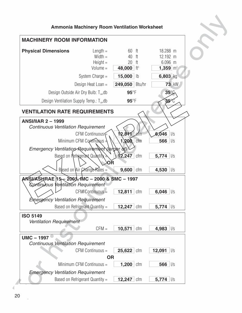
Refer to the following pages for an example of the Minimum Ventilation Worksheet anda Ventilation System Illustration.
5.2 Design Procedure
The ventilation system design is made following the recommended ventilation designconsiderations as presented in Section 3. Details on the calculated ventilation rates arepresented in the ventilation worksheet following this section.
a. First, emergency and non-emergency ventilation rates are established for themachinery room. The emergency machinery room ventilation rate should bebased on the quantity of refrigerant in the largest system with a minimumemergency ventilation rate of at least 10 cfm/ft2 [50.8 l/s per m^2] with aminimum of 20,000 cfm [9,439 l/s]. If that is not practical, a ventilation system
16

For h
istor
ical r
efer
ence
onl
ythat yields at least 12 air changes per hour should be considered. Theemergency ventilation rate based on the quantity of refrigerant in the largestsystem is:
The emergency ventilation rate based on the recommended minimum emergency ventilation rate is 10 cfm/ft2 [50.8 l/s] would be:
For this machinery room, the emergency ventilation at a rate of 10 cfm/ft2
[50.8 l/s per m^2] is greater than the recommended minimum of 20,000 cfm[9,439 l/s]. By comparison, the ventilation rate required to achieve 12 air changesper hour is:
The siting and layout of this machinery room can accommodate an emergencyventilation rate based on 10 cfm/ft2 [50 l/s per m^2]; consequently, we proceed with a design emergency ventilation rate of 24,000 cfm [11,342 l/s].
The non-emergency intermittent ventilation rate is based on limiting the maximum airtemperature rise in the machinery room to no more than 18°F [10°C].
Q G= ⋅ = ⋅ =100 100 15000 12 247, cfm
Q GSI SI= ⋅ = ⋅ =[ ]70 70 6804 5 774, l/s
′ = ⋅ ⋅= × =Q A cfm / ft cfm10 40 60 10 24 00022cfm / ft ft ft ,
= ⋅Q A 50 8 1. .′
SI 2 2 18 3 50 8 11 342,m ml ⋅. .= × s/ l s/ l s/=
Qnon emergency− =⋅ ( )
249 050 Btu/hr1 08 18ºF
,.
= 12 811, cfm
Qnon emergency SI− =⋅ ( ) =
,
,.
,73 156 kW1 21 10ºC
6 046 l s/T
17
QV t
= =× ×
=5
40 60 205
9 600ft ft f
cfm,
QV
SISI= =
× ×=
0 3
12 2 18 3 6 10 3
4 530.
. . ..
,m m m
l s/

For h
istor
ical r
efer
ence
onl
yBased on the machinery room heat load, an non-emergency intermittentventilation rate of 12,811 cfm [6,046 l/s] is needed.
IIAR 2 recommends that a minimum ventilation rate of 0.5 cfm per ft2 [2.54 l/sper m^2] of machinery room be applied. For the 2,400 ft2 [223 m2] machineryroom in this case, a continuous non-emergency ventilation rate of 1,200 cfm[566 l/s] is required. Section 3.2.3 above recommends a minimum continuousventilation rate of between 1 – 2 cfm per ft2 [5-10 l/s per m2] of machineryroom. Based on a minimum continuous ventilation rate of 1.5 cfm per ft2, theminimum continuous ventilation rate would be 3,600 cfm [1,700 l/s].
b. The heating required to warm 3,600 cfm [1,700 l/s] of non-emergencyintermittent ventilation air from 20°F [-6.7°C] to 60°F [15.6°C] is 155,520Btu/hr [45.6 kWT]. A load calculation estimates wall and roof heat losses at 90,000 Btu/hr [26.4 kWT]. The total machinery room heating requirement is245,520 Btu/hr [72 kWT]. Two unit heaters, each rated at 200,000 Btu/hr [58.6 kWT], are selected.
c. Two exhaust fans are selected for ventilating the machinery room. The first fanis sized for 7,000 cfm [3,312 l/s] and the second for 17,000 cfm [8,030 l/s] fora total of 24,000 cfm [11,327 l/s] at 1/4" w.g. [62.3 Pa] static pressure. Thesmaller fan is selected with an 1800/900 rpm drive motor for two-speedoperation. Based on 600 ft/min [3 m/s] velocity through the free area of theintake louvers, four louver sections are selected with 10 ft2 [0.9 m2] of freearea each. They are equipped with fail-open motorized dampers which areinterlocked to the exhaust fans. Other fan combinations may be used if the use of two-speed motors, maximum starter size, etc. dictate.
d. Equipment is located per the “Ventilation System Illustration” shown in Figure 3.Note that the intake louvers and exhaust fans are located to minimize shortcircuiting of air. Also note the location of the emergency ventilation switch justoutside of the exit door. An additional emergency ventilation switch is locatedoutside the machinery room door inside the facility.
e. The two-speed fan operates continuously on low speed, unless temperaturecontrols or the ammonia detector call for high speed operation, at which time thesecond fan also starts. Note that temperature controls and the ammonia detectorare located in reasonable proximity to this exhaust fan to get more representativeindication of temperature and ammonia concentration in the room.
18

For h
istor
ical r
efer
ence
onl
y
Figure 3: Ventilation System Illustration
19
For h
istor
ical r
efer
ence
onl
yAmmonia Machinery Room Ventilation Worksheet
MACHINERY ROOM INFORMATION
Physical Dimensions Length = 60 ft 18.288 mWidth = 40 ft 12.192 m
Height = 20 ft 6.096 mVolume = 48,000 ft3 1,359 m3
System Charge = 15,000 lb 6,803 kg
Design Heat Loan = 249,050 Btu/hr 73 kW
Design Outside Air Dry Bulb: Toa,db 95°F 35°C
Design Ventilation Supply Temp.: Tsa,db 95°F 35°C
VENTILATION RATE REQUIREMENTS
ANSI/IIAR 2 – 1999Continuous Ventilation Requirement
CFM Continuous = 12,811 cfm 6,046 l/sMinimum CFM Continuous = 1,200 cfm 566 l/s
Emergency Ventilation Requirement (larger of)
Based on Refrigerant Quantity = 12,247 cfm 5,774 l/sOR
Based on Air Change Rates = 9,600 cfm 4,530 l/s
ANSI/ASHRAE 15 – 2001, IMC – 2000 & SMC – 1997Continuous Ventilation Requirement
CFM Continuous = 12,811 cfm 6,046 l/s
Emergency Ventilation Requirement
Based on Refrigerant Quantity = 12,247 cfm 5,774 l/s
ISO 5149 Ventilation Requirement
CFM = 10,571 cfm 4,983 l/s
UMC – 1997Continuous Ventilation Requirement
CFM Continuous = 25,622 cfm 12,091 l/sOR
Minimum CFM Continuous = 1,200 cfm 566 l/s
Emergency Ventilation Requirement
Based on Refrigerant Quantity = 12,247 cfm 5,774 l/s
20

For h
istor
ical r
efer
ence
onl
yAmmonia Machinery Room Ventilation Worksheet
MACHINERY ROOM INFORMATION
Physical Dimensions Length = __________ ft _____________ mWidth = __________ ft _____________ m
Height = __________ ft _____________ mVolume = ft3 m3
System Charge = lb kg
Design Heat Loan = Btu/hr kW
Design Outside Air Dry Bulb: Toa,db __________ °F_____________ °C
Design Ventilation Supply Temp.: Tsa,db __________ °F_____________ °C
VENTILATION RATE REQUIREMENTS
ANSI/IIAR 2 – 1999Continuous Ventilation Requirement
CFM Continuous = cfm l/sMinimum CFM Continuous = cfm l/s
Emergency Ventilation Requirement (larger of)
Based on Refrigerant Quantity = cfm l/sOR
Based on Air Change Rates = cfm l/s
ANSI/ASHRAE 15 – 2001, IMC – 2000 & SMC – 1997Continuous Ventilation Requirement
CFM Continuous = cfm l/s
Emergency Ventilation Requirement
Based on Refrigerant Quantity = cfm l/s
ISO 5149Ventilation Requirement
CFM = cfm l/s
UMC – 1997Continuous Ventilation Requirement
CFM Continuous = cfm l/sOR
Minimum CFM Continuous = cfm l/s
Emergency Ventilation Requirement
Based on Refrigerant Quantity = cfm l/s
21

For h
istor
ical r
efer
ence
onl
y6 REFERENCES
ANSI/ASHRAE-15, Safety Standard for Refrigeration Systems, American Society ofHeating Refrigerating and Air-Conditioning Engineers, Atlanta, GA, (2001).
ANSI/IIAR 2, American National Standard for Equipment, Design, and Installation ofAmmonia Mechanical Refrigerating Systems, International Institute of AmmoniaRefrigeration, Arlington, VA, (1999).
Fenton, D. L., Khan, A. S., Kelley, R. D., Chapman, K. S., “Combustion CharacteristicsReview of Ammonia-Air Mixtures”, ASHRAE Transactions, American Society ofHeating, Refrigerating, and Air-Conditioning Engineers, Atlanta, GA, Vol.101, Part 2,Paper number 3922, pp. 476-485, (1995).
IIAR Bulletin 112, Guidelines for: Ammonia Machinery Room Design, InternationalInstitute of Ammonia Refrigeration, Arlington, VA, (1998).
ISO 5149, Mechanical refrigerating systems used for cooling and heating – Safetyrequirements, International Organization for Standardization, Geneva, Switzerland,(1993).
International Mechanical Code, International Code Council, Falls Church, VA (2000).
Khan, A. S., Kelley, R. D., Chapman, K. S., Fenton, D. L., “Flammability Limits ofAmmonia-Air Mixtures”, ASHRAE Transactions, American Society of Heating,Refrigerating, and Air-Conditioning Engineers, Atlanta, GA, Vol.101, Part 2, Papernumber 3920 (RP-682), pp. 454-462, (1995).
National Mechanical Code, Building Officials and Code Administrators International,Country Club Hills, IL, (1993).
Standard Mechanical Code, Southern Building Code Congress International, Inc.,Birmingham, AL, (1997).
Uniform Mechanical Code, International Conference of Building Officials, Whittier, CA, (1997).
22

For h
istor
ical r
efer
ence
onl
yINFORMATIVE APPENDIX A
MACHINERY ROOM HEAT LOAD CALCULATIONS
The first step in determining a ventilation rate based either on a temperature limit ortemperature rise is to estimate the total machinery room heat load. The primary source ofheat in a machinery room is attributable to motor loads. For electric motor prime movers,the rate of heat production is a function of the motor power and the motor efficiency:
(Btu/hr)
[kWT]
where,
qmotor is the motor’s heat production rate (Btu/hr) [kWT],
2545 is simply a conversion from HP to Btu/hr,
HPmotor is the rated motor horse power,
kWe is the motor power expressed in [kW (electric)], and
ηmotor is the motor efficiency expressed as a decimal fraction.
If the efficiency values of the electric motors in the machinery room vary significantly,the motor heat loads to the machinery room should be estimated separately for themotors. If the majority of the electric motors in the machinery room have efficiencies ina narrow range, the total heat load can be estimated based on the sum of the totalmotor power with an average motor efficiency.
For internal combustion engine prime movers, the majority of the engine’s waste heat willbe rejected through the engine’s liquid coolant system; however, a portion of the engine’swaste heat will be lost to the machinery room environment. The proportion of heat lossfrom the internal combustion engine to the machinery room will vary depending on theconfiguration of engine’s subsystems such as exhaust manifolding, oil sump, etc. and theexposure of these subsystems to the surrounding environment. As a guide, one couldexpect that between 5-15% of the energy input to the engine will be lost as heat to thesurrounding machinery room environment. Individual engine manufacturers can becontacted for more detailed heat loss information on their specific products.
The heat load on the engine room due to transmission from the outdoor environment shouldalso be estimated. For those portions of the machinery room that are exposed to the outdoorenvironment, the heat load due to transmission can be estimated by the following:
q HPmotor motor motor= ⋅ ⋅ −( )2545 1 η
q kWmotor e motor= ⋅ −( )[ ]1 η
23

For h
istor
ical r
efer
ence
onl
y
where,
qtransmission is the machinery room heat load due to transmission through theenvelope (Btu/hr) [kWT],
U is the overall heat transfer coefficient for the envelope component suchas a wall or roof (Btu/hr-ft2-°F) [kWT/m2-°C],
A is the envelope component area (ft2) [m2],
Toutside is the outside air temperature including the effects of solar radiation incident on the envelope surface (°F) [°C], and
TER is the design machinery room temperature (°F) [°C].
The outside air temperature used in estimating the transmission gain to the machineryroom needs to be adjusted for solar radiation effects. Chapter 12 of the ASHRAERefrigeration Handbook provides information on allowances for solar effects. Table 4can be used as a guide for increasing the design outside air temperature to account for solar effects.
Table 4: Temperature allowances for solar effects(ASHRAE Refrigeration Handbook, 1998)
Typical Surface Surface OrientationTypes East South West Horizontal
Dark Colored Surfaces
• Slate roofing 8 °F 5 °F 8 °F 20 °F
• Tar roofing [4.4 °C] [2.8 °C] [4.4 °C] [11.1 °C]
• Black paint
Medium colored Surfaces
• Unpainted wood
• Brick 6 °F 4 °F 6 °F 15 °F
• Red Tile [3.3 °C] [2.2 °C] [3.3 °C] [8.3 °C]
• Dark Cement
• Red, gray, or green paint
Light colored surfaces
• White stone 4 °F 2 °F 4 °F 9 °F
• Light colored cement [2.2 °C] [1.1 °C] [2.2 °C] [5 °C]
• White paint
24
q UA T Ttransmission outside ER= −( )
For h
istor
ical r
efer
ence
onl
yThe ASHRAE Handbook of Fundamentals (Chapter 27) provides design outside air drybulb temperatures for 1,459 locations around the world. For purposes of determiningheat gain by transmission through machinery room walls, the 0.4% design conditionsshould be used.
The total heat load on the machinery room is the sum of the internal equipment loadsand the gains through the envelope, or
Once an estimate of the total heat load is obtained, the required ventilation rate can bedetermined by the following:
(cfm)
[m3/s]
where,
Qcontinuous is the ventilation rate required on a continuous basis (ft3/min) [m3/s],
qtotal is the machinery room heat load (Btu/hr) [kWT],
Tsupply is the temperature of air being supplied to the engine room (usually the outdoor air dry bulb temperature) in °F [°C], and
TER is the design machinery room temperature (°F) [°C].
In the case of both IIAR 2 and ASHRAE-15, the quantity (Tsupply – TER) is equal to 18°F[10 °C] since the continuous ventilation is designed to limit the temperature rise.
In the case of the UMC, the machinery room temperature is limited to 104°F [40°C]. Inthis case, the values of Tsupply and TER need to be quantified separately. The design valueof TER is 104°F [40°C]. In most cases, the value of Tsupply will be the design outdoor air drybulb temperature for the location of interest. In some cases, the design outdoor air drybulb temperature will approach the specified machinery room temperature limit and therequired ventilation rate will not be reasonable. In this case, the machinery room supplyair temperature may be reduced (by applying technologies such as evaporative cooling,mechanical cooling, etc.) to allow reasonable values of continuous ventilation rates to be established.
T Tcontinuous
total
supply ER
=⋅ −( )1 08.
T Tcontinuous SI
total SI
supply ER
,,
.=
⋅ −( )
1 21
25
q q qtotal motor transmission= +

For h
istor
ical r
efer
ence
onl
y
International Institute of Ammonia Refrigeration1110 North Glebe Road, Suite 250
Arlington, VA 22201Phone: (703) 312-4200 Fax: (703) 312-0065
Website: www.iiar.org