american national standard for evaluating welding pads ... · welding blankets except that welding...
TRANSCRIPT

American National Standard
for Evaluating Welding Pads,
Welding Blankets and Welding Curtains for Hot Work Operations
ANSI/FM Approvals 4950
February 2007
©2007 FM Approvals LLC. All rights reserved.

Foreword
NOTE: This foreword is introductory only and is not part of American National Standard/FM Approvals 4950.
This standard is intended to verify that the products described will meet stated conditions of performance andquality. The purpose of this Standard is to present the criteria for evaluating various types of welding blankets,pads and curtains to be used as guidance for manufacturers, users and authorities having jurisdiction.
This American National Standard has been developed by the canvass method of standards development of theAmerican National Standards Institute (ANSI). FM Approvals is an ANSI-accredited standards developingorganization (SDO).
Approval of an American National Standard requires verification by ANSI that the principles of openness anddue process have been followed and that a consensus of those directly and materially affected by the standardhas been achieved. Consensus requires that all views and objections be considered, and that a concerted effortbe made toward their resolution. Consensus is established when, in the judgment of the ANSI Board of StandardsReview, substantial agreement has been reached.
The American National Standards Institute does not develop standards nor will it in any circumstances give aninterpretation of any American National Standard. Requests for interpretations of this test standard should beaddressed to FM Approvals.
ANSI regulations require that this American National Standard shall be revised, reaffirmed or withdrawn withinfive years of the date of publication.

TABLE OF CONTENTS
I. INTRODUCTION1.1 Purpose .............................................................................................................................................................................. 11.2 Scope ................................................................................................................................................................................. 11.3 Basis for Requirements ..................................................................................................................................................... 21.4 System of Units ................................................................................................................................................................. 2
2. APPLICABLE DOCUMENTS ................................................................................................................................................ 22.1 Applicable Documents ...................................................................................................................................................... 22.2 Glossary ............................................................................................................................................................................. 2
3. GENERAL REQUIREMENTS ............................................................................................................................................... 33.1 Background ........................................................................................................................................................................ 33.2 Categories .......................................................................................................................................................................... 33.3 Requirements ..................................................................................................................................................................... 4
4. TEST REQUIREMENTS ......................................................................................................................................................... 54.1 Welding Pads and Welding Blankets ................................................................................................................................ 54.2 Welding Curtains ............................................................................................................................................................... 54.3 Other Information .............................................................................................................................................................. 6
5. PERFORMANCE REQUIREMENTS ................................................................................................................................... 65.1 Welding Pads ..................................................................................................................................................................... 65.2 Welding Blankets .............................................................................................................................................................. 75.3 Welding Curtains ............................................................................................................................................................... 8
APPENDIX A: Units of Measurement ....................................................................................................................................... 10
APPENDIX B: Test Method for Evaluating Welding Pads, Blankets and Curtains .......................................................... 11B-1 Test Apparatus ................................................................................................................................................................ 11B-2 Operating Conditions and Procedures ........................................................................................................................... 12B-3 General Test Arrangement ............................................................................................................................................. 14B-4 Fire and Thermal Resistance Test .................................................................................................................................. 15B-5 Paper Ignition Test ......................................................................................................................................................... 16B-6 Performance Requirements ............................................................................................................................................ 17
APPENDIX C: Test Method for Charring Embrittlement .................................................................................................... 18C-1 Test Apparatus and Arrangement ................................................................................................................................... 18C-2 Test Procedure ................................................................................................................................................................ 19C-3 Performance Requirements ............................................................................................................................................ 19
APPENDIX D: Accelerated Weathering Test .......................................................................................................................... 20D-1 Purpose ........................................................................................................................................................................... 20D-2 Test Apparatus ................................................................................................................................................................ 20D-3 Test Sample .................................................................................................................................................................... 20D-4 Test Conditions and Duration ........................................................................................................................................ 20

I. INTRODUCTION
1.1 Purpose
This standard states test requirements for welding pads, welding blankets and welding curtains for use in hotwork operations. These items are intended to be used as fire resistant covers that prevent the ignition ofcombustibles due to welding, cutting and other hot work operations.
1.2 Scope
1.2.1 This standard sets performance requirements for welding pads, welding blankets and welding curtains usedas a means of preventing the ignition of combustibles during welding, cutting and other hot workoperations.
1.2.2 The fire performance of a fire resistant cover depends on the type of welding function to which it will besubjected. In general, welding pads, welding blankets and welding curtains are evaluated on theirability to:
• prevent burn through of the material and provide adequate protection for adjacent combustibles frompossible sources of ignition;
• limit temperature transmission through the material to a degree that will prevent ignition to underlyingcombustibles;
• resist melting, dripping or deformation so as to prevent sparks from spreading outside of confined andprotected areas;
• maintain their flexibility, durability and structural integrity when charred areas are subjected to 90°bends;
• maintain their fire and temperature rise resistance properties when subjected to accelerated weatheringtests intended to simulate exposure to light and water (ultra violet [uv] and condensation, respectively)conditions.
1.2.3 This standard is not intended to determine the suitability for all end use conditions of a product. Conditionsunder which welding pads, welding blankets and welding curtains are used vary widely. For example,these materials may be subjected to environments not anticipated by this standard. It is the responsibilityof the end user to determine the suitability of the welding pad, welding blanket or welding curtain for thespecific hot work operation.
1.2.4 This standard does not address the issue of toxicity or out-gassing of the materials when they are subjectedto molten or other fire conditions resulting from hot work operations.
1.2.5 The use of the materials evaluated to this standard does not take the place of or eliminate the need toobserve other hot work precautions such as the issuance of hot work permits, fire watches or the need topractice other safety precautions recommended NFPA 51B, or whenever Hot Work precautions arerequired.
February 2007 ANSI/FM 4950
FM APPROVALS 1
1.3 Basis for Requirements
1.3.1 The requirements of this standard are based on experience, research and testing and/or the standards ofother national and international organizations. The advice of manufacturers, users, trade associations andloss control specialists was also considered.
1.3.2 The requirements of this standard reflect tests and practices used to examine characteristics of weldingpads, welding blankets and welding curtains for hot work operations.
1.4 System of Units
Units of measurement are U.S. customary units. These are followed by their arithmetic equivalents inInternational System (SI) units, enclosed in parentheses. Appendix B lists the selected units for qualities dealtwith in testing these products; conversions to SI units are included. Conversion of U.S. customary units is inaccordance with ANSI/IEEE/ASTM SI 10-97, Standard for Use of the International System of Units (SI): TheModern Metric System.
2. APPLICABLE DOCUMENTS
2.1 Applicable Documents
The following are standards, test methods and practices referenced in this standard:
American Society for Testing and Materials (ASTM) G-53 - 96, Standard Practice for Operating Lightand Water Exposure Apparatus (Fluorescent UV-Condensation Type) for Exposure of NonmetallicMaterials
National Fire Protection Association (NFPA) 51B, Standard for Fire Prevention During Welding, Cuttingand Other Hot Work (1999)
Test Method for Evaluating Welding Pads, Blankets and Curtains (Appendix B)
Test Method for Assessing Charring Embrittlement (Appendix C)
2.2 Glossary
Charring the formation of a carbonaceous residue as the result of pyrolysis or incomplete combustion.
Fill the yarn running selvage to selvage at right angle to the warp. Also commonly referred toas the cross machine direction.
Hot work any work involving burning, welding, cutting or similar operations that produces sparks,flames or heat that is capable of initiating fires or explosions.
Ignition the initiation or continuance of combustion.
Molten substance metals in their liquified, elevated temperature state, as well as related non-metallicsubstances such as slag, dross and salt, handled at elevated temperatures.
ANSI/FM 4950 February 2007
2 FM APPROVALS

Warp the yarn running lengthwise in a woven fabric. Also commonly referred to as the machinedirection.
Welding blanket a heat resistant fabric designed to be placed in the vicinity of a hot work operation. Intendedfor use in horizontal applications with light to moderate exposures such as that resultingfrom chipping, grinding, heat treating, sand blasting and light horizontal welding. Designedto protect machinery and prevent the ignition of combustibles such as wood that are locatedadjacent to the underside of the blanket.
Welding curtain a heat resistant fabric designed to be placed in the vicinity of a hot work operation. Intendedfor use in vertical applications with light to moderate exposures such as that resulting fromchipping, grinding, heat treating, sand blasting and light horizontal welding. Designed toprevent sparks from escaping a confined area.
Welding pad a heat resistant fabric designed to be placed directly under a hot work operation such aswelding or cutting. Intended for use in horizontal applications with severe exposures suchas that resulting from molten substances or heavy horizontal welding. Designed to preventthe ignition of combustibles that are located adjacent to the underside of the pad.
3. GENERAL REQUIREMENTS
3.1 Background
3.1.1 One of the leading sources of ignition in industrial fires and explosions are sparks and other products ofcombustion resulting from hot work operations. Numerous safe practice guidelines exist addressing thisissue; however, hot work operations continue to be a leading cause of industrial fires and explosions. Thistest standard was developed as a means of assessing heat resistant fabrics and covers that are frequentlyused to protect combustibles in the immediate vicinity of the hot work. The use of materials evaluated inthis standard is not intended to replace any of the currently established and recognized safe practices butis intended to supplement any such guidelines.
3.1.2 The term hot work encompasses a wide range of operations but is generally used to describe welding andits allied processes such as, but not limited to, cutting, heat treating, grinding, chipping, molten splash,sand blasting, thawing pipe, powder driven fasteners, hot riveting and any other similar application thatproduces a spark, flame or heat that can become a source of ignition.
3.2 Categories
3.2.1 This document establishes three distinct categories with specific acceptance criteria for each of theapplications most likely to be encountered. The three categories offered in this standard are welding pads,welding blankets and welding curtains.
February 2007 ANSI/FM 4950
FM APPROVALS 3
3.2.2 Welding pads are intended to be used for the most severe hot work operations. They are typically placedhorizontally directly under the hot work operation and subjected to molten substances. In order to preventthe molten substances from igniting combustibles located under the welding pad, the welding pad must becapable of resisting burn through caused by contact with the molten substance as well as possessingtemperature transmission limiting properties that will keep temperatures on the underside of the weldingpad from reaching temperatures that can ignite typical combustibles. For the purpose of developing thisstandard, a typical combustible found under a welding pad was assumed to be paper having an ignitiontemperature of 500°F (260°C).
3.2.3 Welding blankets are intended to be used for hot work operations that are less severe than those anticipatedfor welding pads. They are used in horizontal applications and provide protection for equipment andcombustibles located in the vicinity of the hot work operation but are not expected to be subjected tomolten substances. In order to provide protection for equipment and prevent ignition of combustibleslocated under the welding blanket, the welding blanket must be capable of resisting burn through causedby contact with sparks, flames and heat resulting from light to moderate hot work operations. In addition,they must also possess temperature transmission limiting properties that will keep temperatures on theunderside of the welding blanket from reaching levels that can ignite typical combustibles. For the purposeof developing this standard, a typical combustible found under a welding blanket was assumed to be wood.A limiting temperature of 500°F (260°C) has been selected as representative of temperatures associatedwith the endothermic phase of the thermal degradation of wood.
3.2.4 Welding curtains are intended to be used for hot work operations that are similar to those anticipated forwelding blankets except that welding curtains are designed to be used in vertical applications. Theyprovide protection for combustibles located in the vicinity of the hot work operation by preventing sparksand other sources of ignition from escaping a confined area. Welding curtains must be capable of resistingmelting, burning, burn through and deformation caused by contact with sparks, flames and heat resultingfrom light and moderate hot work operations. Welding curtains must also remain flexible and dimension-ally stable at all times thereby preventing sparks from spreading outside the intended confined area.
3.3 Requirements
3.3.1 For each material submitted for examination, the following product information shall be provided:
• product trade name or designation,
• general description,
• intended usage and category,
• Material Safety Data Sheets, if applicable
3.3.2 Prior to conducting tests for evaluation as a welding pad, welding blanket or welding curtain, samples shallbe conditioned at 73°F ± 5°F (23°C ± 3°C) at 50% (±5%) relative humidity for a period of not less than72 hours. All samples shall be tested within 2 hours of removal from the conditioning area.
3.3.3 Welding Pads and Welding Blankets – A minimum of eight (8) samples shall be needed for each materialthat is tested. Four (4) samples shall be taken with the warp (machine) direction parallel to the longdimension of the sample and four (4) samples shall be taken with the fill (cross machine) directionperpendicular to the long dimension. Samples shall be permitted to be taken from the same piece of cloth;however, individual samples shall be taken from different areas of the same cloth that are separated by aminimum of 1 ft (0.3 m). As an alternative, the samples may be taken from separate pieces of cloth. Alltest samples shall be 12 in. ± 1 in. x 18 in. ± 1 in. (0.31 m ± 25 mm x 0.46 m ± 25 mm).
ANSI/FM 4950 February 2007
4 FM APPROVALS

3.3.4 Welding Curtains – A minimum of two (2) samples shall be needed for each material that is tested. Theyshall be taken with the warp (machine) direction parallel to the long dimension of the sample. Samplesshall be permitted to be taken from the same piece of cloth; however, individual samples shall be takenfrom different areas of the same cloth that are separated by a minimum of 1 ft (0.3 m). As an alternative,the samples may be taken from separate pieces of cloth. All test samples shall be 12 in. ± 1 in. x 18 in.± 1 in. (0.31 m ± 25 mm x 0.46 m ± 25 mm).
4. TEST REQUIREMENTS
4.1 Welding Pads and Welding Blankets
4.1.1 Each material shall be subjected to the following tests in accordance with the Test Method for EvaluatingWelding Pads, Blankets and Curtains (Appendix B).
Sample 1 Fire and Thermal Resistance Test – warp direction parallel to the long dimension
Sample 2 Fire and Thermal Resistance Test – fill direction perpendicular to the long dimension
Sample 3 Paper Ignition Test – warp direction parallel to the long dimension
Sample 4 Paper Ignition Test – fill direction perpendicular to the long dimension
4.1.2 Following the tests shown in 4.1.1, all samples shall be subjected to the Test Method for CharringEmbrittlement (see Appendix C).
4.1.3 Upon completion of the tests shown in 4.1.1 and 4.1.2 above, an attempt will be made to determine whichof the four (4) test specimen(s) is (are) the most critical. A new, previously untested sample of each testspecimen(s) that is (are) deemed to be critical shall be subjected to the Accelerated Weathering Test (seeAppendix D).
4.1.4 Upon completion of the Accelerated Weathering Test, each test specimen shall be subjected to thecorresponding test in the most applicable orientation deemed critical.
4.1.5 Upon completion of the tests shown in 4.1.4, all samples shall be subjected to the Test Method for CharringEmbrittlement.
4.2 Welding Curtains
4.2.1 Each material shall be subjected to the Test Method for Evaluating Welding Pads, Blankets and Curtains(Appendix B).
4.2.2 Upon completion of the test shown in 4.2.1 a new, previously untested specimen shall be subjected to theAccelerated Weathering Test (see Appendix D).
4.2.3 Upon completion of the Accelerated Weathering Test, the test specimen shall be subjected to the TestMethod for Evaluating Welding Pads, Blankets and Curtains.
February 2007 ANSI/FM 4950
FM APPROVALS 5

4.3 Other Information
4.3.1 Based on the test procedures contained in this document, welding pads are exposed to the most severe testconditions and have the strictest acceptance criteria. As such, samples that meet the performance criteriaas welding pads shall be considered to have qualified for use as welding blankets. They shall be qualifiedfor use as welding curtains provided that they maintain their flexibility and dimensional stability and donot melt or deform.
4.3.2 Based on the test procedures contained in this document, welding blankets and welding curtains areexposed to similar test conditions, with the welding blanket having the more critical acceptance criteria.As such, welding blankets shall be considered to have qualified for use as welding curtains provided thatthey maintain their flexibility and dimensional stability and do not melt or deform.
4.3.3 Welding pads, welding blankets and welding curtains that meet the criteria contained in this Standard shallnot be limited in size as it pertains to the length or width of the finished product provided they are ofseamless construction. Seams provided along the outer perimeter of the item shall be allowed.
4.3.4 Welding pads, welding blankets and welding curtains that incorporate a seamed construction to join twoor more individual pieces together shall be assessed. If the seam construction is judged to be consistentwith the field of the material, no additional testing shall be required. If the construction of the seam isjudged to be different from the field of the material, additional tests shall be conducted on samples thatincorporate the particular type of seam. In these cases, the seam shall be located such that it will beexposed to the most critical location and orientation during testing. The seamed and non-seamed areas ofthe samples shall meet all criteria contained in this Standard.
5. PERFORMANCE REQUIREMENTS
5.1 Welding Pads
In order to qualify as a welding pad, the welding pad must exhibit its ability to protect typical combustibleslocated directly underneath it from igniting when subjected to molten substances by satisfying the performancecriteria for each of the tests shown below.
5.1.1 Test Method for Evaluating Welding Pads, Welding Blankets and Welding Curtains
A. Requirement
The ability of a horizontally placed welding pad to resist flame propagation and burn through andexhibit temperature transmission limitation properties.
B. Test/Verification
The test arrangement used to obtain this data shall be the Welding Pads, Blankets and Curtains TestApparatus (see Appendix B, Figures B-1 and B-2).
ANSI/FM 4950 February 2007
6 FM APPROVALS

Performance shall be considered satisfactory if all samples meet the following conditions:
Fire and Thermal Resistance Test
• there shall be no burn through of the pad;
• no individual thermocouple placed on the underside of the pad shall exceed 500°F (260°C);
• exposed areas that exhibit charring shall not crack when subjected to the Test Method for AssessingCharring Embrittlement. (See Appendix C).
Paper Ignition Test
• there shall be no sign of ignition on any surface of the paper
5.1.2 Test Method for Evaluating Welding Pads, Blankets and Curtains After Exposure to AcceleratedWeathering.
A. Requirement
The ability of a horizontally placed welding pad to resist flame propagation and, burn through andexhibit temperature transmission limitation properties after exposure to accelerated weatheringconditions.
B. Test/Verification
The test arrangement used to obtain this data shall be the Accelerated Weathering Test (Appendix D)and the Test Method for Evaluating Welding Pads, Blankets and Curtains (see Appendix B).
Performance shall be considered satisfactory if the sample meets the conditions shown inparagraph 5.1.1 after being exposed to 1000 hours of accelerated weathering and then subjected to theTest Method for Evaluating Welding Pads, Blankets and Curtains (both the Fire and ThermalResistance Test and the Paper Ignition Test).
5.2 Welding Blankets
In order to qualify a welding blanket, the welding blanket must exhibit its ability to prevent equipment andcombustibles located directly underneath it from igniting when subjected to sparks, flames and heat resultingfrom light to moderate welding by satisfying the performance criteria for each of the tests shown below.
5.2.1 Test Method for Evaluating Welding Pads, Blankets and Curtains
A. Requirement
The ability of a horizontally placed welding blanket to resist flame propagation and burn through, andexhibit temperature transmission limitation properties.
B. Test/Verification
The test arrangement used to obtain this data shall be Welding Pads, Blankets and Curtains TestApparatus (see Appendix B, Figures B-1 and B-2).
Performance shall be considered satisfactory if all samples meet the following conditions:
Fire and Thermal Resistance Test
• there shall be no burn through of the blanket;
• no individual thermocouple placed on the underside of the pad shall exceed 500°F (260°C);
• exposed areas that exhibit charring shall not crack when subjected to the Test Method for AssessingCharring Embrittlement. (See Appendix D). The areas that have been exposed to any molten metalor slag along the centerline of the burn pattern shall be excluded from this requirement
February 2007 ANSI/FM 4950
FM APPROVALS 7
Paper Ignition Test
• discoloration of the paper shall be permitted
• any burn holes in the paper shall be limited such that a 1 in. (25 mm) diameter sphere can not passthrough the opening without making contact with the periphery of the burn area.
5.2.2 Test Method for Evaluating Welding Pads, Blankets and Curtains After Exposure to AcceleratedWeathering.
A. Requirement
The ability of a horizontally placed welding blanket to resist flame propagation and burn through, andexhibit temperature transmission limitation properties after exposure to Accelerated Weathering.
B. Test/Verification
The test arrangement used to obtain this data shall be the Accelerated Weathering Test (Appendix D)and the Welding Pads, Blankets and Curtains Test Apparatus (see Appendix B, Figures B-1 and B-2).
Performance shall be considered satisfactory if the sample meets the conditions shown inparagraph 5.2.1 after being exposed to 1000 hours of accelerated weathering and then subjected to theTest Method for Evaluating Welding Pads, Blankets and Curtains (both the Fire and ThermalResistance Test and the Paper Ignition Test).
5.3 Welding Curtains
In order to qualify as a welding curtain, the welding curtain must exhibit its ability to provide protection forcombustibles located in the vicinity of the hot work operation from igniting when subjected to sparks and othersources of ignition, to maintain its flexibility and dimensional stability.
5.3.1 Test Method for Evaluating Welding Pads, Welding Blankets and Welding Curtains
A. Requirement
The ability of a vertically placed welding curtain to resist melting, burning, burn through anddeformation caused by contact with sparks, flames and heat resulting from light and moderate hot workoperations.
B. Test/Verification
The test arrangement used to obtain this data shall be Welding Pads, Blankets and Curtains(see Appendix B, Figures B-1 and B-2).
Performance shall be considered satisfactory if all samples meet the following conditions:
• there shall be no melting, burning or burn through on the curtain;
• when hung vertically, it shall remain flexible such that a minimum 2 in. (51 mm) of slack can be laidflat on the floor at all times
5.3.2 Test Method for Evaluating Welding Pads, Blankets and Curtains After Exposure to AcceleratedWeathering.
A. Requirement
The ability of a vertically placed welding curtain to resist melting, burning, burn through anddeformation caused by contact with sparks, flames and heat resulting from light and moderate hot workoperations after exposure to accelerated weathering conditions.
ANSI/FM 4950 February 2007
8 FM APPROVALS

B. Test/Verification
The test arrangement used to obtain this data shall be the Accelerated Weathering Test (Appendix D)and the Test Method for Evaluating Welding Pads, Blankets and Curtains (see Appendix B).
Performance shall be considered satisfactory if the sample meets the following conditions after beingexposed to 1000 hours of accelerated weathering and then subjected to the Test Method for EvaluatingWelding Pads, Blankets and Curtains.
• there shall be no melting, burning or burn through on the curtain;
• when hung vertically, it shall remain flexible such that a minimum 2 in. (51 mm) of slack can be laidflat on the floor at all times
February 2007 ANSI/FM 4950
FM APPROVALS 9

APPENDIX A
Units of Measurement
LENGTH: in. – ‘‘inches’’, ft – ‘‘feet’’(mm – ‘‘millimeters’’), (m - ‘‘meters’’)mm = in. × 25.4, m = ft × 0.3048
AREA: in2 – ‘‘square inches’’, ft2 – ‘‘square feet’’(mm2 – ‘‘square millimeters’’)(m2 – ‘‘square meters’’)mm2 = in2 × 6.4516 × 102
m2 = ft2 × 0.0929
VELOCITY: ft/s – ‘‘feet per second’’(m/s – ‘‘meters per second’’)m/s = ft/s × 0.3048
HEAT: Btu – ‘‘British thermal units’’(kW/h – ‘‘kilowatt hours’’)kW/h = Btu × 0.000293
PRESSURE: psi – ‘‘pounds per square inch’’(kPa – ‘‘kilopascals’’)kPa = psi × 6.8948
TEMPERATURE: °F – ‘‘degrees Fahrenheit’’(°C – ‘‘degrees Celsius’’)°C = (°F – 32) × 5/9
ANSI/FM 4950 February 2007
10 FM APPROVALS
APPENDIX B
Test Method for Evaluating Welding Pads, Blankets and Curtains
CAUTION – This test uses a high temperature cutting flame. A certified welding cutter is required tooperate all equipment.
B-1 Test Apparatus
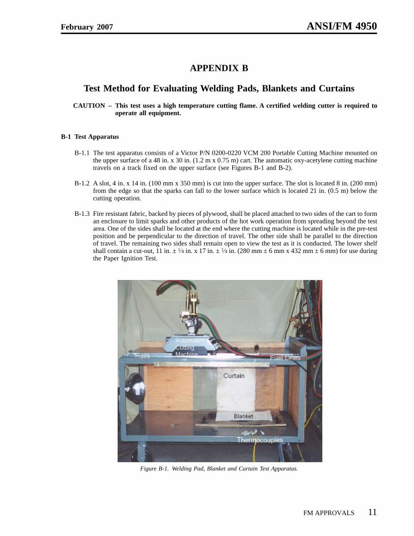
B-1.1 The test apparatus consists of a Victor P/N 0200-0220 VCM 200 Portable Cutting Machine mounted onthe upper surface of a 48 in. x 30 in. (1.2 m x 0.75 m) cart. The automatic oxy-acetylene cutting machinetravels on a track fixed on the upper surface (see Figures B-1 and B-2).
B-1.2 A slot, 4 in. x 14 in. (100 mm x 350 mm) is cut into the upper surface. The slot is located 8 in. (200 mm)from the edge so that the sparks can fall to the lower surface which is located 21 in. (0.5 m) below thecutting operation.
B-1.3 Fire resistant fabric, backed by pieces of plywood, shall be placed attached to two sides of the cart to forman enclosure to limit sparks and other products of the hot work operation from spreading beyond the testarea. One of the sides shall be located at the end where the cutting machine is located while in the pre-testposition and be perpendicular to the direction of travel. The other side shall be parallel to the directionof travel. The remaining two sides shall remain open to view the test as it is conducted. The lower shelfshall contain a cut-out, 11 in. ± 1⁄4 in. x 17 in. ± 1⁄4 in. (280 mm ± 6 mm x 432 mm ± 6 mm) for use duringthe Paper Ignition Test.
Figure B-1. Welding Pad, Blanket and Curtain Test Apparatus.
February 2007 ANSI/FM 4950
FM APPROVALS 11

B-2 Operating Conditions and Procedures
B-2.1 A certified cutting operator shall be required to operate the test apparatus.
B-2.2 The operating conditions shall be as follows:
Oxygen Regulator Pressure 43 psis ± 1 psig (296 kPa ± 7 kPa)
Acetylene Regulator Pressure 8.5 psig ± 0.5 psig (59 kPa ± 3 kPa)
Cutting Machine Speed 13 in./min (330 mm/min)
Length of Cut 12 in. (+ 0.25 in., -0 in.)
Travel Time 55 sec ± 5 sec
Steel Plate Size 12 in. (+ 0.25 in., -0 in.) x 8 in. (+ 0.25 in., -0 in.)
Plate Thickness 0.75 in. ± 0.08 in. (19 mm ± 2 mm)
Plate Material ASTM C-1018
Figure B-2. Welding Pad, Blanket and Curtain Test Apparatus.
ANSI/FM 4950 February 2007
12 FM APPROVALS

B-2.3 The set-up for the cutting torch flame shall be as follows:
a) Set the output pressure for the acetylene regulator at 8.5 psig ± 0.5 psig (59 kPa ± 3 kPa) and theoutput pressure for the oxygen regulator at 43 psig ± 1 psig (296 kPa ± 7 kPa).
b) Open the acetylene toggle valve (the local valve at the automatic cutting machine that controls theflow of acetylene) and then ignite the acetylene flame.
c) Check to ensure that the oxygen cutting valve (the final valve near the torch head that allows full flowof oxygen) is closed. This allows a limited flow of oxygen in order to prevent pre-heating of the steelplate.
d) Open the oxygen toggle valve and allow oxygen to flow to the torch.
e) Adjust the flame so that it produces a ring of small flame jets at the torch tip. Position the torch flameagainst the steel plate edge. Adjust the flame to ensure that the tips of the flame jets just impinge the uppersurface of the steel plate.
f) With the flame properly adjusted, the cutting machine shall be locked into the drive position using thelevers on the end of the machine.
g) Open the oxygen cutting valve on the torch. This will produce a high temperature cutting flame. Ifproperly adjusted, the flame should display a double-fluted flame under cutting conditions (seeFigures C-3a and C-3b).
h) The torch shall travel the length of the steel plate within the travel time noted above. Upon completingthe cutting operation, the flame shall be extinguished by closing all valves.
Figure B-3a. Figure B-3b.Torch Tip Flame During Pre-Heating.
February 2007 ANSI/FM 4950
FM APPROVALS 13
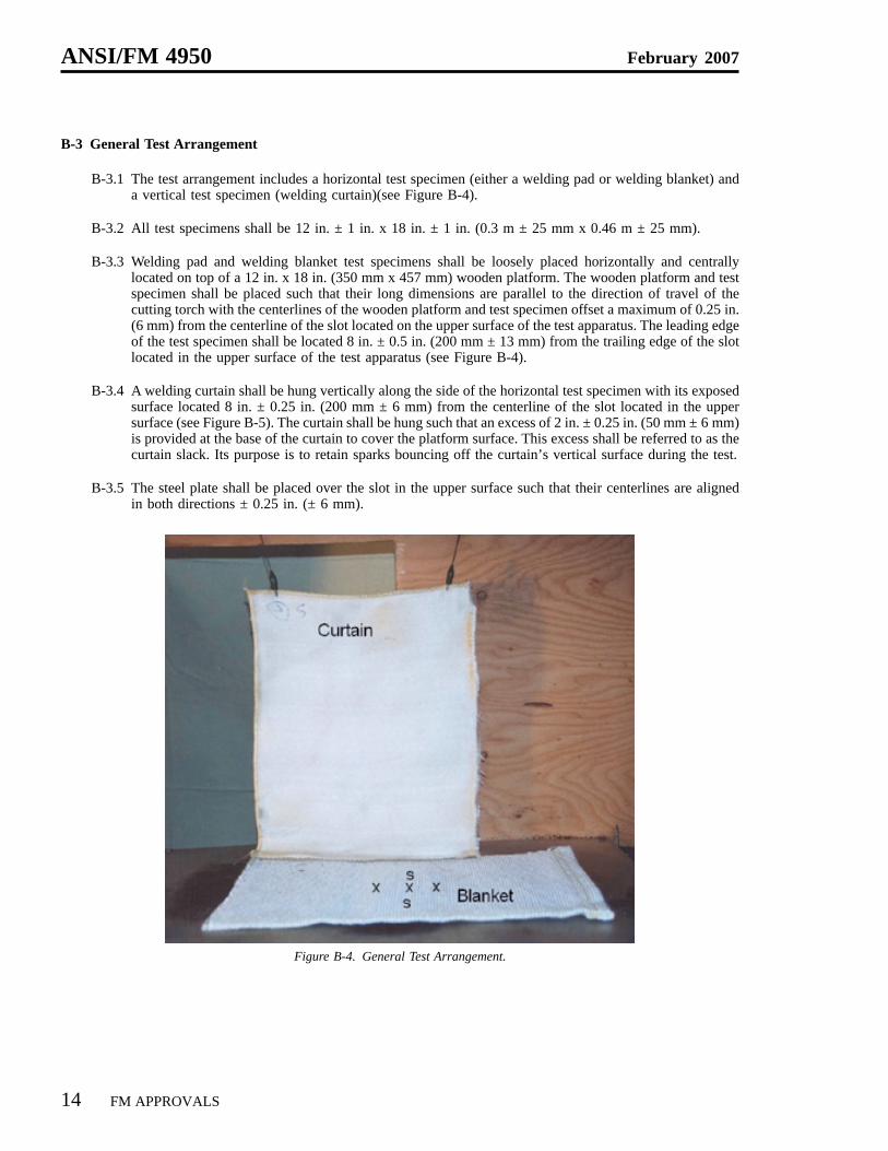
B-3 General Test Arrangement
B-3.1 The test arrangement includes a horizontal test specimen (either a welding pad or welding blanket) anda vertical test specimen (welding curtain)(see Figure B-4).
B-3.2 All test specimens shall be 12 in. ± 1 in. x 18 in. ± 1 in. (0.3 m ± 25 mm x 0.46 m ± 25 mm).
B-3.3 Welding pad and welding blanket test specimens shall be loosely placed horizontally and centrallylocated on top of a 12 in. x 18 in. (350 mm x 457 mm) wooden platform. The wooden platform and testspecimen shall be placed such that their long dimensions are parallel to the direction of travel of thecutting torch with the centerlines of the wooden platform and test specimen offset a maximum of 0.25 in.(6 mm) from the centerline of the slot located on the upper surface of the test apparatus. The leading edgeof the test specimen shall be located 8 in. ± 0.5 in. (200 mm ± 13 mm) from the trailing edge of the slotlocated in the upper surface of the test apparatus (see Figure B-4).
B-3.4 A welding curtain shall be hung vertically along the side of the horizontal test specimen with its exposedsurface located 8 in. ± 0.25 in. (200 mm ± 6 mm) from the centerline of the slot located in the uppersurface (see Figure B-5). The curtain shall be hung such that an excess of 2 in. ± 0.25 in. (50 mm ± 6 mm)is provided at the base of the curtain to cover the platform surface. This excess shall be referred to as thecurtain slack. Its purpose is to retain sparks bouncing off the curtain’s vertical surface during the test.
B-3.5 The steel plate shall be placed over the slot in the upper surface such that their centerlines are alignedin both directions ± 0.25 in. (± 6 mm).
Figure B-4. General Test Arrangement.
ANSI/FM 4950 February 2007
14 FM APPROVALS

B-4 Fire and Thermal Resistance Test
B-4.1 The Fire and Thermal Resistance Test configuration shall incorporate seven (7) thermocouples locateddirectly under the welding pad or welding blanket test specimen and directly on top of the underlyingwooden platform. All the thermocouples shall be placed along the centerline of the long dimension of thewooden platform, ± 1⁄8 in. (± 3 mm). Using the end of the wooden platform where the oxy- acetylenetorch starts the test as a datum, the thermocouples shall be located at 3 in., 6 in., 8 in., 9 in., 10 in., 12 in.and 15 in. ± 1⁄8 in. (76, 152, 204, 229, 254, 305 and 381 mm, ± 3 mm) respectively from the datum (seeFigure B-5). Each of the thermocouples shall be a K-type (Omega WTK – 6 – 36 – M or equal)thermocouple.
B-4.2 Once all thermocouples and the test specimen are in place, the torch flame shall be lit and the testconducted in accordance with Paragraph B-2.
B-4.3 Upon completion of the test, that sample shall be removed from the test apparatus and examined.
Figure B-5. Thermocouple Arrangement – Fire and Thermal Resistance Test.
February 2007 ANSI/FM 4950
FM APPROVALS 15

B-5 Paper Ignition Test
B-5.1 The Paper Ignition Test configuration shall incorporate a recessed expanded open wire metal tray, paperand a test specimen. The piece of paper is placed directly on top of the metal tray which has been recessed2.5 in. ± 1⁄4 in. (64 mm ± 6 mm) below the lower shelf of test apparatus (see Figure B-6 and B-7). Thepurpose of the paper is to determine if the temperature transmission limitation capabilities through thespecimen is sufficient to prevent typical combustibles located beneath the welding pad from ignitingduring hot work operations.
B-5.2 The piece of paper to be used shall be new, previously unused and be specified as white copy paperhaving a nominal basis weight of 20 lbs/ream (75 g/m2) . The paper shall have nominal sheet dimensionsof 11 in. x 17 in. (279 mm x 432 mm). The paper shall be centered under the test specimen such that paperand test specimen long dimensions are parallel. All paper shall be conditioned at 73°F ± 5°F(23°C ± 3°C) at 50% (±5%) relative humidity prior to use for a minimum 24 hour period. Individualpieces of paper shall be hung vertically so that both surfaces shall be exposed while being conditioned.Each sheet shall be used within two (2) hours of being removed from the conditioning area.
B-5.3 The test specimen shall be placed in clamps located along the top of the lower shelf of the test apparatussuch that it is held taut in the clamps.
B-5.4 Once the paper sheet and the test specimen are in place, the torch flame shall be lit and the test conductedin accordance with Paragraph B-2.
B-5.5 Upon completion of the test, that sample shall be removed from the test apparatus and examined.
Figure B-6. Tray Arrangement During the Paper Ignition Test.
ANSI/FM 4950 February 2007
16 FM APPROVALS

B-6 Performance Requirements
Performance requirements for each test specimen shall be as shown below:
Welding Pads – see Paragraph 5.1 of this Standard
Welding Blankets – see Paragraph 5.2 of this Standard
Welding Curtains – see Paragraph 5.3 of this Standard
Figure B-7. Paper Tray Below Welding Pad or Blanket – Paper Ignition Test.
February 2007 ANSI/FM 4950
FM APPROVALS 17
APPENDIX C
Test Method for Charring Embrittlement
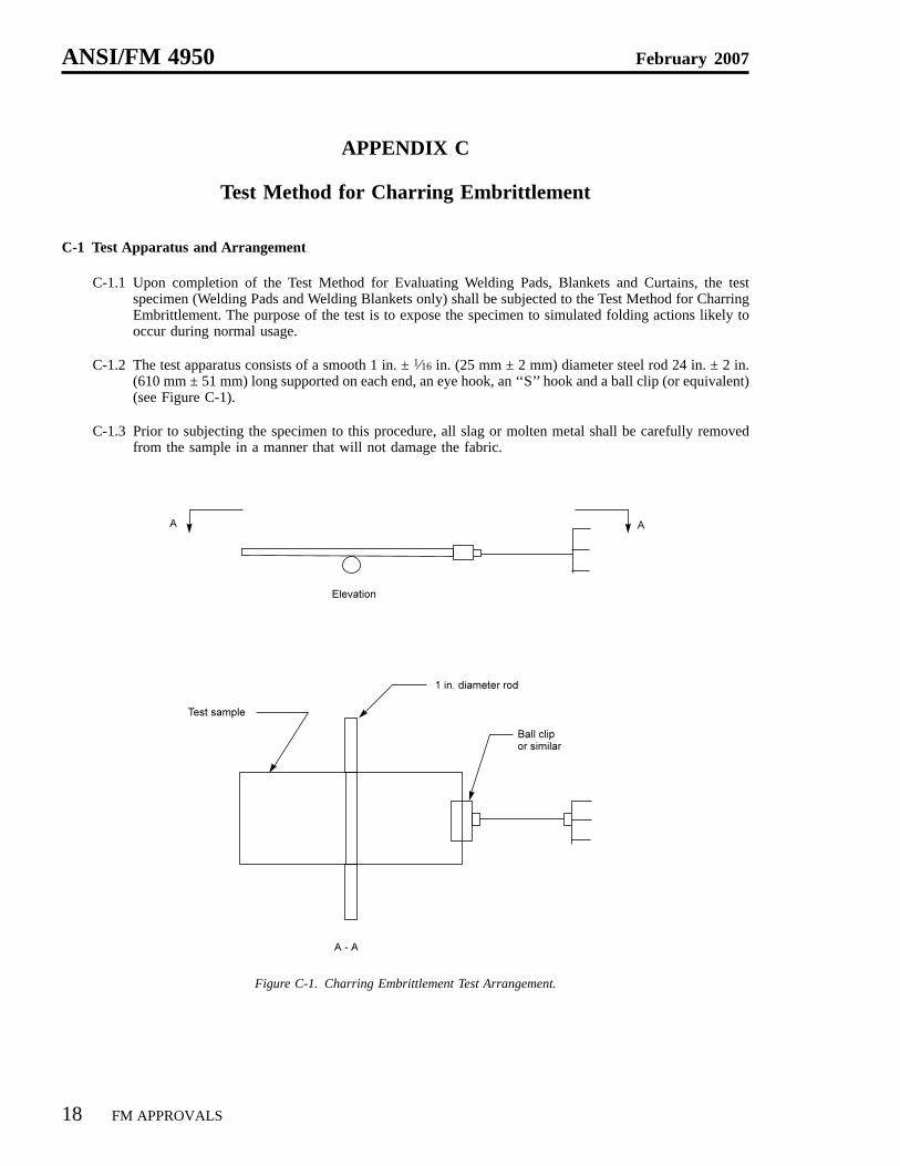
C-1 Test Apparatus and Arrangement
C-1.1 Upon completion of the Test Method for Evaluating Welding Pads, Blankets and Curtains, the testspecimen (Welding Pads and Welding Blankets only) shall be subjected to the Test Method for CharringEmbrittlement. The purpose of the test is to expose the specimen to simulated folding actions likely tooccur during normal usage.
C-1.2 The test apparatus consists of a smooth 1 in. ± 1⁄16 in. (25 mm ± 2 mm) diameter steel rod 24 in. ± 2 in.(610 mm ± 51 mm) long supported on each end, an eye hook, an ‘‘S’’ hook and a ball clip (or equivalent)(see Figure C-1).
C-1.3 Prior to subjecting the specimen to this procedure, all slag or molten metal shall be carefully removedfrom the sample in a manner that will not damage the fabric.
Figure C-1. Charring Embrittlement Test Arrangement.
ANSI/FM 4950 February 2007
18 FM APPROVALS

C-2 Test Procedure
C-2.1 One end of the test specimen is placed in the jaws of the ball clip. With the long dimension of the testspecimen perpendicular to the 1 in. (25 mm) diameter rod and the charred surface face up, the specimenis placed over the rod with the central location of the charred area directly above the centerline of the rod± 1 in. (25 mm). The specimen shall be pulled taut and level. Care shall be taken to keep the specimenas flat as possible prior to the start of the test.
C-2.2 Keeping tension on the specimen, the end away from the clip shall be lowered (to simulate folding of theunit) using the rod as a pivot point. The end of the specimen shall be lowered using a smooth, fluidmotion until it forms a 90° ± 5°angle when looking sideways at the assembly. Keeping tension on thespecimen, it shall then be raised in a smooth, fluid motion (to simulate unfolding of the unit) until it isreturned to the starting position. This procedure shall be repeated four (4) more times on each specimen.
C-2.3 The specimen shall then be turned over such that the charred area is face down. The procedure shownin C-2.2 above shall be repeated with the specimen in this position a total of five (5) times.
C-2.4 The specimen shall then be turned back over (charred area face up), removed from the ball clip androtated 90°such that the long dimension of the specimen is parallel to the rod. The specimen is placedover the rod with the central location of the charred area directly above the centerline of the rod ±1 in.(25 mm). The specimen shall be pulled taut and level. Care shall be taken to keep the specimen as flatas possible prior to the start of the test. The procedure shown in C-2.2 above shall be repeated with thespecimen in this position a total of five (5) times.
C-2.5 The specimen shall then be turned over such that the charred area is face down. The procedure shownin C-2.2 above shall be repeated with the specimen in this position a total of five (5) times.
C-2.6 Upon completion of the above, the specimen shall be examined for evidence of cracking of the charredmaterial and the development of through openings.
C-3 Performance Requirements
Performance requirements for each test specimen shall be as shown in Paragraph 5.1.1 or 5.2.1 of this Standard,as applicable.
February 2007 ANSI/FM 4950
FM APPROVALS 19

APPENDIX D
Accelerated Weathering Test
D-1 Purpose
The Accelerated Weathering Test shall be used to determine the effect caused by water and ultraviolet (UV)exposure on the fire performance characteristics of the product. This test is intended to simulate the deteriorationcaused by water such as rain or dew and the ultraviolet energy of sunlight. It is not intended to simulate thedeterioration caused by localized weather phenomena such as atmospheric pollution, biological attack or saltwater exposure.
D-2 Test Apparatus
D-2.1 The test apparatus is constructed of corrosion resistant materials enclosing eight (8) fluorescent UVlamps (two banks of four), a heated water pan, test specimen racks and provisions for controlling andindicating operating times and temperatures. For further details, refer to ASTM G-53 - 96, StandardPractice for Operating Light and Water Exposure Apparatus (Fluorescent UV-Condensation Type) forExposure of Nonmetallic Materials. The UV source shall utilize bipin UV-B type lamps having a nominalrating of 40 W when operated from a ballast providing a controlled current of 430 mA at 102V. The lampsshall have a peak emission of 313 nm.
D-2.2 This method utilizes an array of fluorescent lamps as the UV source with lamp emission concentrated inthe UV range. The condensation is produced by exposing the test surface to a heated, saturated mixtureof air and water vapor while the reverse side of the test specimen is exposed to the cooling influence ofambient room air.
D-3 Test Sample
The test sample shall be representative of the product being examined. The sample shall measure12 in. ± 1 in. x 18 in. ± 1 in. (0.31 m ± 25 mm x 0.46 m ± 25 mm). It shall be mounted in the specimen rackswith the test surface facing the lamps.
D-4 Test Conditions and Duration
Samples shall be placed in the test apparatus and conditioned for 1000 hours (+ 72 hrs, -0 hrs). The cycle timeshall be 8 hours (± 0.1 hrs) UV at 140°F ± 5°F (60°C ±3°C) followed by 4 hours of condensation at122°F ± 5°F (50°C ± 3°C).
ANSI/FM 4950 February 2007
20 FM APPROVALS

Printed in USA