american changer & hoffman mint
TRANSCRIPT
1
AMERICAN CHANGER & HOFFMAN MINT
We Are Changing the Industry℠
1400 N. W. 65
th Place, Fort Lauderdale, Florida 33309
T: (+1) 954-917-3009 F: (+1) 954-917-3079
www.americanchanger.com www.hoffmanmint.com
Parts & Service: (888)741-9840
Service Fax: (954)917-5204
Sales: (800)741-9840
To order parts only, visit our website: www.americanchanger.com
Service Questions? E-mail: [email protected]
Revised January 2016
“TICKET STATION” –
OPERATIONS MANUAL
MODEL AC107
2
Model Number: ________________________
Serial Number: ________________________
Tested By: ________________________
Date: ________________________

3
Specifications
Operating voltage 120VAC +10% to -15%
Power consumption Controller: 100W
Operating temperature 0 - 120 degrees Fahrenheit
Interface to hoppers 24VDC, 2.5 amps max.
Interface to validators 24VAC, 1.5 amps max.
Hopper coin capacities 100/hopper minimum to 10,000/hopper maximum (20,000 total maximum)
Warranty Information
A Return Material Authorization number (RMA #) must be obtained before returning a unit for repair. A copy of invoices must accompany any and all
warranty work.
It is the end users’ responsibility to follow cleaning and maintenance
procedures as outlined in the validator manual. Any unit returned for repair requiring only a cleaning will be charged a flat
rate plus shipping and handling.
Validators
Validators are warranted for two years from date of purchase.
Hopper(s) and/or Dispenser(s) and Logic Board
These items are warranted for one year from date of purchase.
COVERED
Manufacturers’ defects in workmanship or materials
NOT COVERED
Damage caused by shipping or physical abuse Misapplication Vandalism
End users’ attempt, on their own, to repair components Cleaning and maintenance Power surges and lightning strikes

4
Table of Contents
SECTION A: SETUP & INSTALLATION
Setup of the AC107 Ticket Station . . . . . . . . . . . . . . . . . . . . . . . . . . 5
Assembling the Ticket Station . . . . . . . . . . . . . . . . . . . . . . . . . . . . . 5
Mounting Instructions . . . . . . . . . . . . . . . . . . . . . . . . . . . . . . . . . 5
Installing Coin Cup . . . . . . . . . . . . . . . . . . . . . . . . . . . . . . . . . . . . . 6
Installing Bill Stacker . . . . . . . . . . . . . . . . . . . . . . . . . . . . . . . . . . . 6
Hopper Coin/Token Sizes & General Information . . . . . . . . . . . . . . . 7
Flex I/O Board . . . . . . . . . . . . . . . . . . . . . . . . . . . . . . . . . . . . . . . 7
Main Logic Board . . . . . . . . . . . . . . . . . . . . . . . . . . . . . . . . . . . . . 8
Flex Vending Station Features . . . . . . . . . . . . . . . . . . . . . . . . . . . . 9
Programming the Machine . . . . . . . . . . . . . . . . . . . . . . . . . . . . . . . 10-13
Menu Index, Info and Audit Reports . . . . . . . . . . . . . . . . . . . . . . . . . 14-15
Remote Loading Software onto the Flex Board . . . . . . . . . . . . . . . . . 16-17
Replacing Printer Paper . . . . . . . . . . . . . . . . . . . . . . . . . . . . . . . . . 18-19
Functional Description of the AC110_A Ticket Station. . . . . . . . . . . . . . 20
Functional Operation of the Hopper Out-of-Service Conditions . . . . . . 20
Condor Coin Mechanism . . . . . . . . . . . . . . . . . . . . . . . . . . . . . . . . . 21
SECTION B: MAINTENANCE
American Changer Cleaning Kit Information . . . . . . . . . . . . . . . . . . . 22
5
SECTION A
SETUP & INSTALLATION
Setup Inspect for any connectors or components that may have been dislodged during shipping. The lock and keys for your changer will be inside the manila envelope along with this manual and other pertinent
information. To install the lock, insert the cylinder into the hole in the middle of the T-handle and push until it stops. Turn the key until you hear it “snap." Turn the key counterclockwise ¼ turn and remove the keys.
NOTE: The only way to get a duplicate set of keys made is to save the tag that comes
between the keys. This ID # starts with “AC or ACC ####.”
CELLULAR WIRELESS CREDIT CARD SYSTEM (optional)
This feature is an optional add-on for most American Changer models. A separate maintenance manual is included in your packet. You MUST call American Changer technical support at (888) 741-9840 for
setup and operating instructions. Prior to startup in the wireless mode, the machine will operate and validate cash transactions only.
Assembling the Ticket Station Safety Note: The AC107 comes almost completely assembled, in a box strapped to a pallet. Care must be taken in unpacking and maneuvering the machine into place. It is not a one-man job.
Fill the hoppers with a minimum of 100 coins each to a maximum of 2800 coins.
Locate the on/off switch on the upper right corner of the Flex Main Logic Board (next to the flashing green LED) and turn the machine on.
As the machine comes on the software version scrolls by on the LCD screen, finally stopping with “Welcome! No Credit Cards Now.”
The AC110_A can now be tested and used with cash only. Note* To change payouts, it is necessary to enter the program mode.
Mounting the AC107
IF YOU ARE UNSURE IN ANY WAY IN PROCEEDING WITH THE FOLLOWING STEPS, PLEASE HIRE A LICENSED ELECTRICIAN TO MOUNT YOUR MACHINE FOR YOU!
1. Disconnect any and all AC power going to the machine. (Unplug AC line cord from the Power Module Board and from the wall.)
2. Slide the hopper out of the cabinet.
3. Note: You will need to verify with the building code to see if it is allowable to plug the changer into a 3-prong grounded outlet. If it is not, there must be 120VAC run through conduit or other means to meet local codes to the changer. If it is not required, proceed to step #6.
4. Have the electrician run the conduit, install the new breaker, wire and help decide how the wiring will enter the changer (from the side or the bottom). This will affect the mounting location.
5. After the conduit has been installed, proceed with the mounting.
6. Find an appropriate wall into which to bolt the machine. The wall should have studs or be constructed of concrete.

6
7. NOTE: SECURING THE MACHINE FROM FEWER THAN THE FOUR BOLTS OR WELDED ANGLE
IRON MAY BE DANGEROUS. EACH HOLE NEEDS A BOLT THROUGH IT TO SECURELY MOUNT
THE CHANGER INTO THE WALL. MOUNTING THE CHANGER IN ANY OTHER WAY MAY RESULT IN THE CHANGER BEING TORN FROM OR FALLING FROM THE WALL, RESULTING IN PERSONAL OR CUSTOMER INJURY ALONG WITH ELECTRICAL SHOCK.
8. Choose a height to mount the machine, keeping in mind that a handicapped person in a wheelchair
should still be able to insert a card into the card reader and/or a bill into the bill validator. (We recommend no higher than 4 feet above the ground.)
9. Have someone hold the machine into the wall while someone else marks the holes. CAUTION: THE MACHINE WEIGHS 91 POUNDS; DO NOT EXERT YOURSELF SO THAT YOU MAY CAUSE AN
INJURY.
10. BEFORE DRILLING THE MARKED HOLES, ENSURE THAT THERE ARE NO ELECTRICAL WIRES, TELEPHONE LINES, GAS OR WATER LINES BEHIND THE WALL.
11. After drilling the holes, put the machine’s back into the wall. Thread and tighten bolts.
12. Verify that the machine is securely mounted.
13. If the machine is permanently connected through a conduit, proceed to step #16.
14. Plug the power cord back into an AC wall outlet and into the Power Supply/Relay Board, if necessary.
Do not use an extension cord unless allowed by the building electrical code.
15. Installation is completed. Proceed to the “Programming the Changer” section.
16. In order to continue, you will need to purchase numerous electrical components. We highly
recommend hiring a licensed electrician to perform the following:
a. Install the conduit box on the conduit entering the cabinet in the lower left side of the cabinet. b. Secure the 3 wires (hot, neutral and ground) to the AC wall outlet; the ground wire should also be
directly attached to the cabinet ground terminal. c. Connect the AC line cord into the bottom of the Power Supply/Relay Board.
d. Plug the male end into the AC outlet just installed. e. Properly fold the line cord to avoid sharp corners and any other damage.
17. Proceed to the “Programming the Changer” section.
7
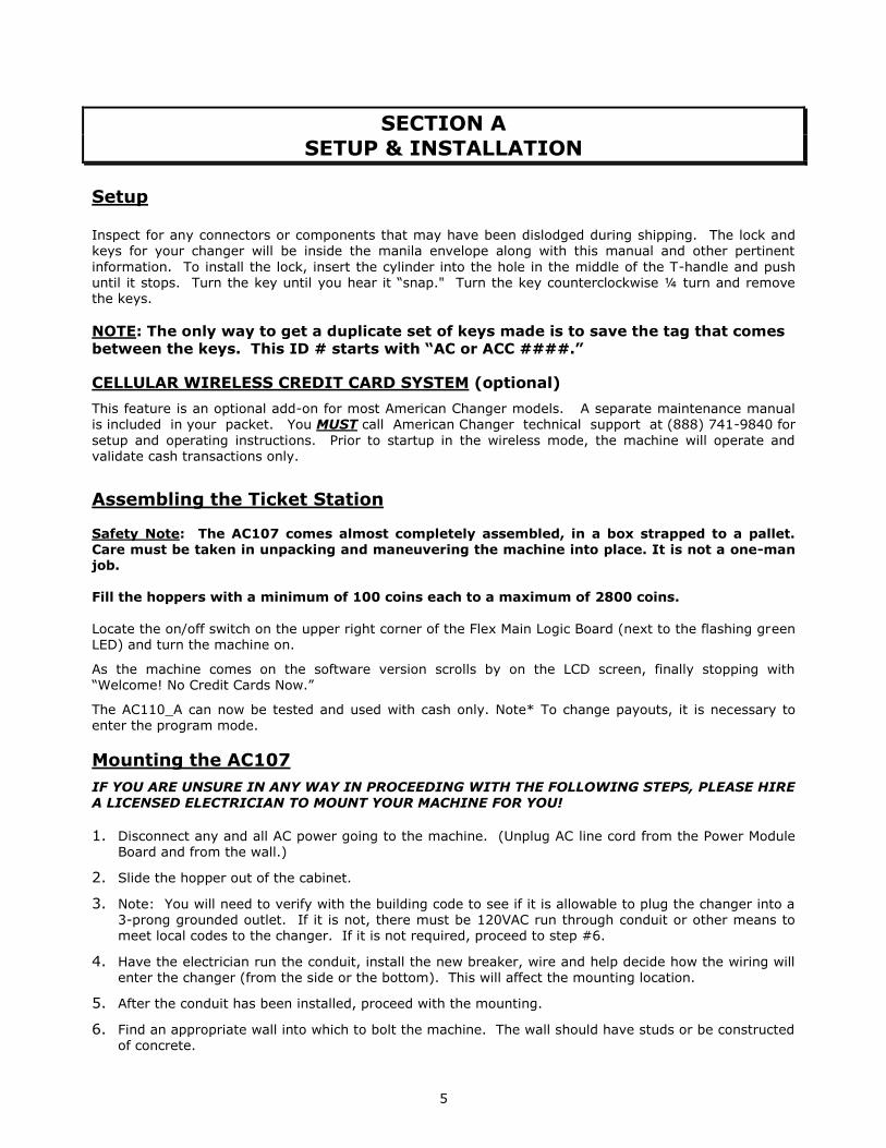
Hopper Coin/Token Sizes & General Information
The hopper will automatically adjust to dispense coins/tokens in size from 20-30 mm in diameter and 1.25-3.5 mm in thickness. There is an option available to dispense smaller coins.
A nickel is approximately 21 mm, a quarter is approximately 25mm, and a dollar coin is approximately 28mm in diameter.
Figure 7 – Hopper
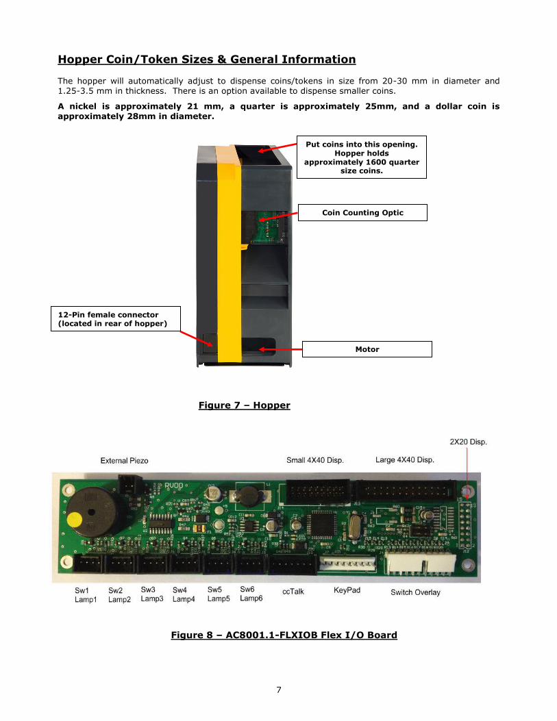
Figure 8 – AC8001.1-FLXIOB Flex I/O Board
Put coins into this opening. Hopper holds
approximately 1600 quarter size coins.
Coin Counting Optic
Motor
12-Pin female connector (located in rear of hopper)

8
Figure 9 – AC8001-FLEXBD Main Logic Board
Dial Tran IP Tran
AC Power Board
USB Select Switch
24 VDC Power
In
On/Off Switch
Hopper 1 Hopper 2
Validator 2 or InOne

9
Flex Vending Station Features The Vending Station system can be used to vend tokens, items, change, tickets and bills.
1 Dispense The hopper content can be defined as either currency by entering its value, for
example, $0.25 or it can be AItems@ which can be tokens, tickets, candy bars,
medallions or anything depending on the installed dispenser type. This is defined by setting the content value to A0". (Initially the system is only using
the regular ACC ccTalk hoppers.)
2 Payment The desired payout and cost must be selected by one of the four buttons.
Once selected, the payment type needs to be selected. Value can be up to $999.99. There are several ways to pay:
2.1 Cash Using either a bill validator and/or a coin acceptor. Deposits are accumulated
until the selected cost is reached and then the item(s) are dispensed. If overpaid, change is given if applicable. A partial payment can be cancelled,
and change is returned if applicable.
2.2 Tokens IDX tokens 2.3 CreditCard A normal swipe & payout cycle is done.
Accepts Visa, MasterCard, American Express and Discover cards. Can use InOne (acceptance is controlled by InOne), DialTran or IPTran. InOne also controls max value ????
2.4 QuickPay A pre-defined payout for each bill value is used, and the payout occurs as soon as the bill or coin is inserted. This is similar to a regular token dispenser with bonus or the old TokenStation. This feature can be disabled by the operator by setting the bill values to 0.
2.5 Changer Full featured changer with remote monitoring
3 System Failures
3.1 Hopper If Aitems@ hopper fails and no second Aitems@ hopper, the display shows an
out of service message. If both hoppers have the same items, payout will be from the functional one. Status of the hoppers can be seen on the System
Info printout. Below are the printed failure messages: Opto=s Hopper opto blocked
No Comm. Hopper not communicating High Current Hopper max current exceeded Low Hopper low in coins Timed Out Hopper timed out on payout
3.2 Validator If the validator fails, the display shows a ACredit Cards only@ message. Status
of the validator can be seen on the System Info printout. Below are the
printed failure messages: Motor Motor failure Sensor Sensor failure
CheckSum Checksum failure Jammed Validator is jammed Cashbox Cashbox removed No Comm. No communication
OutOfService System has tried to enable the validator several times without success
3.3 Credit Card If the credit card processing fails, the display shows a ACash only@ message.
Status of the credit card processing can be seen on the System Info printout. Below are the printed failure messages:
No Comm. No communication No Reader Reader is not connected or defective (only if using
Data Cap)

10
Programming the AC107 TicketStation
The configuration menu can be accessed only if the door is open.
Pressing the select switch on the Flex Board (Figure 9) will bring the display to show “Enter Access Code.”
Use the keypad to enter the access code. The default code from the factory is “1234”
Pressing the select switch again will get the user out of the Menu mode.
Use the keypad to enter the menu number, or press the Back/Next button to step through the menus.
Use the * key to clear and the # key to enter data.
All the menus work the same:
No/Yes: Selects status Back/Next: Selects the item
Exit: Exits the setup menu 01 - Print Help Menu
Prints the Menu Index (Figure 10)
02 - System Info Prints the payout information and configuration settings. The following information is also included
on the System Info Printout.
Software Revision Validator Status Coin Acceptor Status Zip Code Option Status Credit Card Status Hopper #1 Status Printer Status Hopper #2 Status Temperature
03 - Button Price
Select the value for selections 1 thru 4. Here you will enter the price point for each of the four available choices. When entering the price, be sure enter all necessary zeros including the 2 zeros following the decimal point. For Button 1 enter “0005.00” then press the arrow button under the “Next” option. The screen now displays “Button 2”. Enter “0010.00” and press the arrow under the “Next” option. For
Button 3 enter “0020.00” and press the arrow button under the “Next” option. For Button 4 enter “0030.00” and press the arrow under the “Exit” option. Once you select “Exit” you will be brought back to the main menu. If you want different prices enter them following the above steps.
04 - Button Payout Set up payout count for the 4 selection buttons. Here you will enter the quantity of tickets to be dispensed for each of the four available choices. For Button 1 enter “020” then press the arrow button under the “Next” option. The screen now displays “Button 2”. Enter “040” and press the arrow under the “Next” option. For Button 3 enter “080” and press the arrow button under the “Next” option. For Button 4 enter “120” and press the arrow under the “Exit” option. Once you select “Exit” you will be brought back to the
main menu. If you want different token payouts enter them following the previous steps.
05 - Enable Bills Selects which bills to accept and reject. This will only display bills the validator can accept.

11
06 - Payout Table (Only Used for Quick Pay Option) Only bills enabled in Menu 05 will be available in this menu. Enter the number of items to be paid
for each bill type. The first payout option displayed is “$0.**”. This option is used to set the number of tokens paid per quarter. If the quarter is not being accepted press the button under the “Next” option.
Next you will see “$1”. To pay 4 coins for a dollar enter “002” and then press the arrow button under the “Hop1” selection. Do not press the “Next” button at this point. Please use the images below as a guide if necessary. The display will still display “$1” but the option you just selected will have changed to “Hop2”. Enter “002” and press the arrow button under the “Next” option. You will now set up the payout for the “$5”. To payout 20 coins for 5 dollars enter “010” and then press the arrow button under the “Hop1” selection. “Hop2” will be displayed, enter “010” and press the arrow button under the “Next” option. Now set up the payout for the “$10”. To payout 40 coins for 10 dollars enter “020” and then
press the arrow button under the “Hop1” selection. “Hop2” will be displayed, enter “020” and press the arrow button under the “Next” option. Now set up the payout for the “$20”. To payout 80 coins for 20 dollars enter “040” and then press the arrow button under the “Hop1” selection. “Hop2 will be displayed, enter “040” and press the arrow button under the “Exit” option.

12
07 - Enable Hoppers Enable/disable hoppers 1, 2, 3, and/or 4.
08 - Hopper Coin Values Use only for different value coins in each hopper.
Hopper 1= Left hopper Set value of coin to be dispensed from $000.00 to $999.99 Hopper 2= Right hopper Set value of coin to be dispensed from $000.00 to $999.99 Hopper 3= Middle hopper Set value of coin to be dispensed from $000.00 to $999.99 Hopper 4= Middle hopper Set value of coin to be dispensed from $000.00 to $999.99 You will also set whether the hopper is dispensing Change or Tokens by pressing the arrow under “Token”. This will toggle between “Token” and “Change”.
09 - Enable Coin Acceptor Enable/disable the coin acceptor.
10 - Select Devices Select the devices to be disabled. Hop1 Hop2 CassU and CassL. If the device is displayed it is disabled.
11 - Promo Token Payout
Enter the # of items paid for each token type by using the keypad. Up to four different tokens can be
programmed. Use position 7 (7 pulses), 8 (8 pulses), 9 (9 pulses) and A (10 pulses) on the Condor coin acceptor. If using an IDX coin acceptor it will be program med using the number of pulses.
12 - Dump Hoppers Dumps the coins from all hoppers
13 - Audit Information Prints a summary of all the sales (Figure 11). There are separate counters for credit cards and items/change dispensed from hoppers 1 and 2.
Reset: Prints 2 copies of all the audit values and resets all the “Resettable Counters” to 0. Every time Reset button is pushed, the audit sequence number increases by one.
Print: Pushing the Print button prints all the audit values without resetting. All the values are max 99,999 except for the Total Cash value, which is $100,000.00.
14 - Vend Item Name
Choose from Items, Tickets or Tokens. (Currently not used)
15 - Date Setup
Enter the date in this format: YY-MM-DD
16 - Time Setup Enter the time in this format: HH:MM (24-hour format)
17 - Machine Number Use the keypad to enter the Machine Number (Figure 12).
18 - Marquee Timer
Set up the time to turn on/off the marquee.
19 - Zip-code Enable Enable or disable the zip-code verification feature.
20 - Access Code
Reset the access code for entering the Program function.
21 - Key Beep Enable Enable/disable beep when keys are pressed.
22 - Location Name Set the name of the location to be printed on the credit card receipt. 23- Bills Loaded Cassette High (Not used for this machine) Set the quantity of the bills loaded in the top cassette. If using sensors this should be set to 000. 24- Bills Loaded Cassette Middle (Not used for this machine)
Set the quantity of the bills loaded in the bottom cassette. If using sensors this should be set to 000.

13
25- Bill Value Cassette High (Not used for this machine) Set the value of the bill to be dispensed from the top cassette.
26- Bill Value Cassette Middle (Not used for this machine)
Set the value of the bill to be dispensed from the bottom cassette. 27-Printer Options This gives the owner the option of printing a receipt for a credit card transaction The selections are “ALWAYS” “PROMPT” and “NEVER”. The default setting is “ALWAYS.” This also gives the option for printing a receipt for a cash transaction. The selections are “ALWAYS” “PROMPT” and “NEVER” the default setting is “NEVER”.
Set up long or short receipt and full or partial paper cut. 28- Validator Enable Enable or disable the bill validator. For machines with a coin acceptor only this will be set to disable. 29- InOne Test Mode
Troubleshooting for the InOne credit card system. Call American Changer Service before enabling
this feature. 30- Country Set which country the machine will be used in. U.S. or UK.

14
Figure 10 – Help Menu Index

15
Figure 11 – Audit Print Definitions Figure 12 – Machine No. Information
16
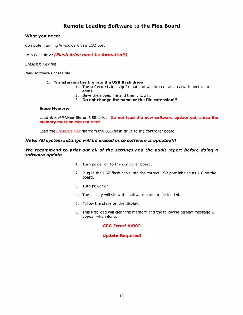
Remote Loading Software to the Flex Board
What you need:
Computer running Windows with a USB port
USB flash drive (Flash drive must be formatted!)
EraseMM.Hex file
New software update file
1. Transferring the file into the USB flash drive 1. The software is in a zip format and will be sent as an attachment to an
email. 2. Save the zipped file and then unzip it. 3. Do not change the name or the file extension!!!
Erase Memory:
Load EraseMM.Hex file on USB drive! Do not load the new software update yet, since the memory must be cleared first!
Load the EraseMM.Hex file from the USB flash drive to the controller board
Note: All system settings will be erased once software is updated!!!
We recommend to print out all of the settings and the audit report before doing a
software update.
1. Turn power off to the controller board.
2. Plug in the USB flash drive into the correct USB port labeled as J18 on the
board.
3. Turn power on.
4. The display will show the software name to be loaded.
5. Follow the steps on the display.
6. This first load will clear the memory and the following display message will appear when done:
CRC Error! V:B03
Update Required!
17
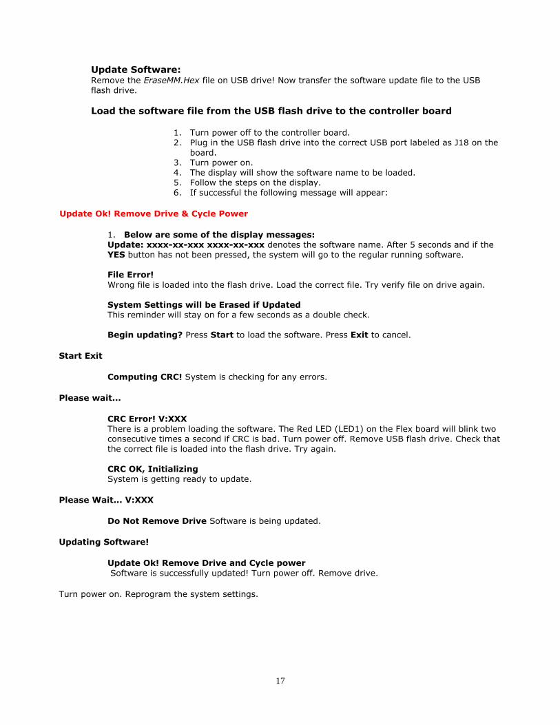
Update Software: Remove the EraseMM.Hex file on USB drive! Now transfer the software update file to the USB flash drive.
Load the software file from the USB flash drive to the controller board
1. Turn power off to the controller board. 2. Plug in the USB flash drive into the correct USB port labeled as J18 on the
board. 3. Turn power on. 4. The display will show the software name to be loaded. 5. Follow the steps on the display. 6. If successful the following message will appear:
Update Ok! Remove Drive & Cycle Power
1. Below are some of the display messages: Update: xxxx-xx-xxx xxxx-xx-xxx denotes the software name. After 5 seconds and if the YES button has not been pressed, the system will go to the regular running software. File Error!
Wrong file is loaded into the flash drive. Load the correct file. Try verify file on drive again. System Settings will be Erased if Updated This reminder will stay on for a few seconds as a double check. Begin updating? Press Start to load the software. Press Exit to cancel.
Start Exit
Computing CRC! System is checking for any errors.
Please wait...
CRC Error! V:XXX There is a problem loading the software. The Red LED (LED1) on the Flex board will blink two consecutive times a second if CRC is bad. Turn power off. Remove USB flash drive. Check that the correct file is loaded into the flash drive. Try again.
CRC OK, Initializing System is getting ready to update.
Please Wait... V:XXX
Do Not Remove Drive Software is being updated.
Updating Software!
Update Ok! Remove Drive and Cycle power
Software is successfully updated! Turn power off. Remove drive.
Turn power on. Reprogram the system settings.

18
Replacing the Printer Paper
Before the printer paper runs out, you might wish to contact your Distributor and order more Printer paper. The part number is AC7071-01, and it is a special brand which is hard to find. Most AC6007 problems occur from the printer. Either the operator buys the wrong paper or has trouble loading the paper. Please follow the steps of either Method #1 or Method #2 below to properly load your thermal printer with new paper.
Figure P1: AC7084 Printer – Rear View
Method #1 – Automatic Feed:
NOTE: This method must be performed with the board power ON.
1. If there is paper remaining on the previous roll, it must be removed before proceeding. Move the “Paper Feed Lever” from the DOWN to the UP position (refer to Figure P2), and then pull out the remaining paper from the rear of the printer and discard the roll.
Figure P2: AC7084 Printer – Side View, with Paper
2. Move the “Paper Feed Lever” back to the DOWN position. Slide a new roll of paper onto the “Roll Holder,” oriented so the paper comes off on the side toward the printer (refer to Figure P3 for the correct placement).
Paper Feed Lever

19
Figure P3: AC7084 Printer – Side View, Showing Proper Roll Placement 3. Wrap the paper under the “Paper Guide” and begin to feed it into the “Paper Slot.” You do not need
to fold or cut the paper in any way; it should be left square in the front. At a certain point as the
paper is being fed in, the printer will detect it and automatically feed it to the printing position. When done, the setup should look like Figure P3.
1. IMPORTANT! Turn OFF the Main Board power, and turn it ON again after a few seconds. Note: The printer will not work until the power has been cycled!
2. Enter the Setup Mode and perform a Printer Test. Make sure the printer prints all of the lines of text and cuts off the paper.
Method #2 – Manual Feed:
NOTE: This method can be performed with the board power ON or OFF. 1. If there is paper remaining on the previous roll, it must be removed before proceeding. Move the
“Paper Feed Lever” from the DOWN to the UP position (refer to Figure P2), and then pull out the remaining paper from the rear of the printer and discard the roll.
2. With the “Paper Feed Lever” still in the UP position, slide a new roll of paper onto the “Roll Holder,”
oriented so the paper comes off on the side toward the printer (refer to Figure P3 for the correct placement).
3. Wrap the paper under the “Paper Guide,” and begin to feed it into the “Paper Slot.” You do not need to fold or cut the paper in any way; it should be left square in the front. Continue to feed the paper into the slot, through the print head, until it passes out through the front of the machine (refer to Figure P4).
4. Move the “Paper Feed Lever” back to the DOWN position. The printer is now ready to print.
5. Enter the Setup Mode and perform a Printer Test. Make sure the printer prints all of the lines of text and cuts off the paper.
Figure P4: AC7084 Printer – Front View, Paper Fed Through

20
Functional Description of the AC107 Ticket Station
After the Ticket Station has been installed and the computer programming complete, the machine is ready to operate. Exiting the “Program” mode will bring up the main Pricing screen.
For cash or credit card transactions, select one of the four arrow buttons to prompt the select payment menu. Once the amount of the ticket transaction has been selected, the Ticket Station will send pulses to the ticket dispenser to dispense tickets. As the transaction ends, the following occurs:
1. The “bills inserted” counters increase the appropriate slots and all other associated audit features.
2. The “hopper” total counter is incremented by the appropriate coins paid out.
3. The “tickets” total counter is incremented by the appropriate tickets paid out.
Functional Operation of the Hopper Out-of-Service Conditions
In a two-hopper system, the other hopper will work as a backup or give change as needed. In a one-
hopper system there is no backup. There are 4 instances that will shut down a hopper: 1. Low Coin – This is the most common occurrence. This shutdown occurs when the coins in the hopper
fall below the gold plates, which conduct low voltage between them. The hopper will dispense coins from the other hopper when the TokenStation reads the signal. Once the first hopper is read to have
“low coins,” a call over the phone line is placed to the pager/Cellphone that one hopper is down. The machine will now dispense all coins from the full hopper. If the other hopper runs out of coins, THE TOKENSTATION WILL CONTINUE TO DISPENSE COINS FROM EITHER HOPPER UNTIL BOTH HOPPERS ARE EMPTY (80-100 COINS WILL REMAIN IN THE HOPPERS). At this time, the machine will page out
again to notify the pager/Cellphone that the second hopper is now empty.
2. Security Failure – There are 2 cases that will cause a security failure. a. The hopper is missing. The hopper is not slid into the hopper plate connector.
b. There is a foreign object or coin lodged in the coin counting window. Remove the side of the hopper with 5 screws and look in the area where the coins exit the hopper. Check the slot for foreign matter and remove it from the slot.
3. Jammed or Timeout Failure – This failure occurs when the hopper is told to dispense coins and, after 45 seconds, no coin has been dispensed. This failure is present when the hopper coin belt is jammed or the hopper has run out of coins. If the coin belt is jammed, repair or replace unit.
4. Over-Pay Failure – This is the error that occurs when the hopper pays out more coins than told to dispense. A very dirty exit sensor most often causes this error.
21
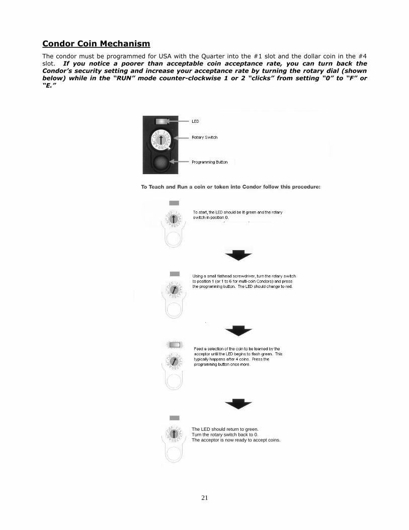
Condor Coin Mechanism
The condor must be programmed for USA with the Quarter into the #1 slot and the dollar coin in the #4 slot. If you notice a poorer than acceptable coin acceptance rate, you can turn back the Condor’s security setting and increase your acceptance rate by turning the rotary dial (shown below) while in the “RUN” mode counter-clockwise 1 or 2 “clicks” from setting “0” to “F” or “E.”
The LED should return to green. Turn the rotary switch back to 0.
The acceptor is now ready to accept coins.
The LED should return to green. Turn the rotary switch back to 0. The acceptor is now ready to accept coins.
22
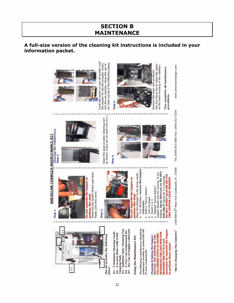
SECTION B
MAINTENANCE
A full-size version of the cleaning kit instructions is included in your
information packet.