amendments - renton
TRANSCRIPT
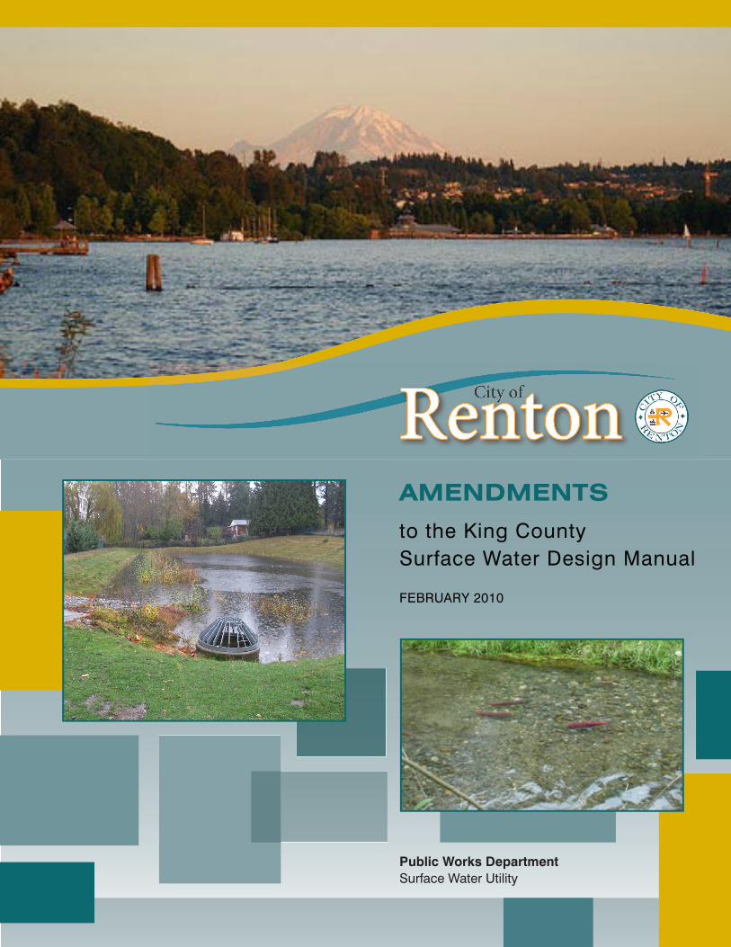
to the King CountySurface Water Design Manual
FEBRUARY 2010
AMENDMENTS
Public Works DepartmentSurface Water Utility

Printed on Recycled Paper
CITY OF RENTON AMENDMENTS TO THE
KING COUNTY
SURFACE WATER DESIGN MANUAL
City of Renton Public Works Department
Surface Water Utility
February 2010

ACKNOWLEDGMENTS
CITY OF RENTON AMENDMENTS TO THE KING COUNTY SURFACE WATER DESIGN MANUAL February 2010 The following individuals are acknowledged for their assistance in the development and approval of the City of Renton Amendments to the 2009 KCSWDM:
Mayor:
Denis Law
City Council: Don Persson, President Terri Briere*, Pres. Pro-Tem Randy Corman Marcie Palmer King Parker* Greg Taylor Rich Zwicker*
* Utilities Committee Members
Support from Other Agencies: Rachel McCrea, Department of Ecology Ed O’Brien, Department of Ecology Steve Foley, King County
City of Renton: Gregg Zimmerman, Public Works Administrator Ron Straka, Surface Water Engineering Supervisor Allen Quynn, Project Manager Neil Watts, Development Services Director Lys Hornsby, Utility Systems Director Chip Vincent, Planning Director Jennifer Henning, Planning Manager Laureen Nicolay, Senior Planner Mike Dotson, Engineering Specialist Kayren Kittrick, Development Engineering Supervisor Rich Marshall, Maintenance Manager Hebe Bernardo, Surface Water Utility Civil Engineer Bob Hanson, Transportation Design Supervisor Chris Sorensen, Assistant Planner
Consultants: Mike Giseburt, R. W. Beck, Inc. Ralph Nelson, R. W. Beck, Inc. Todd Crandell, R. W. Beck, Inc. Derek Booth, Stillwater Sciences

INTRODUCTION TABLE OF CONTENTS
CITY OF RENTON AMENDMENTS TO THE KING COUNTY SURFACE WATER DESIGN MANUAL February 2010

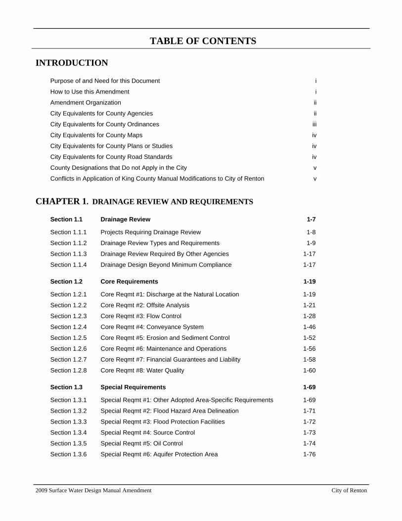
TABLE OF CONTENTS
2009 Surface Water Design Manual Amendment City of Renton
INTRODUCTION
Purpose of and Need for this Document i
How to Use this Amendment i
Amendment Organization ii
City Equivalents for County Agencies ii
City Equivalents for County Ordinances iii
City Equivalents for County Maps iv
City Equivalents for County Plans or Studies iv
City Equivalents for County Road Standards iv
County Designations that Do not Apply in the City v
Conflicts in Application of King County Manual Modifications to City of Renton v
CHAPTER 1. DRAINAGE REVIEW AND REQUIREMENTS
Section 1.1 Drainage Review 1-7
Section 1.1.1 Projects Requiring Drainage Review 1-8
Section 1.1.2 Drainage Review Types and Requirements 1-9
Section 1.1.3 Drainage Review Required By Other Agencies 1-17
Section 1.1.4 Drainage Design Beyond Minimum Compliance 1-17
Section 1.2 Core Requirements 1-19
Section 1.2.1 Core Reqmt #1: Discharge at the Natural Location 1-19
Section 1.2.2 Core Reqmt #2: Offsite Analysis 1-21
Section 1.2.3 Core Reqmt #3: Flow Control 1-28
Section 1.2.4 Core Reqmt #4: Conveyance System 1-46
Section 1.2.5 Core Reqmt #5: Erosion and Sediment Control 1-52
Section 1.2.6 Core Reqmt #6: Maintenance and Operations 1-56
Section 1.2.7 Core Reqmt #7: Financial Guarantees and Liability 1-58
Section 1.2.8 Core Reqmt #8: Water Quality 1-60
Section 1.3 Special Requirements 1-69
Section 1.3.1 Special Reqmt #1: Other Adopted Area-Specific Requirements 1-69
Section 1.3.2 Special Reqmt #2: Flood Hazard Area Delineation 1-71
Section 1.3.3 Special Reqmt #3: Flood Protection Facilities 1-72
Section 1.3.4 Special Reqmt #4: Source Control 1-73
Section 1.3.5 Special Reqmt #5: Oil Control 1-74
Section 1.3.6 Special Reqmt #6: Aquifer Protection Area 1-76
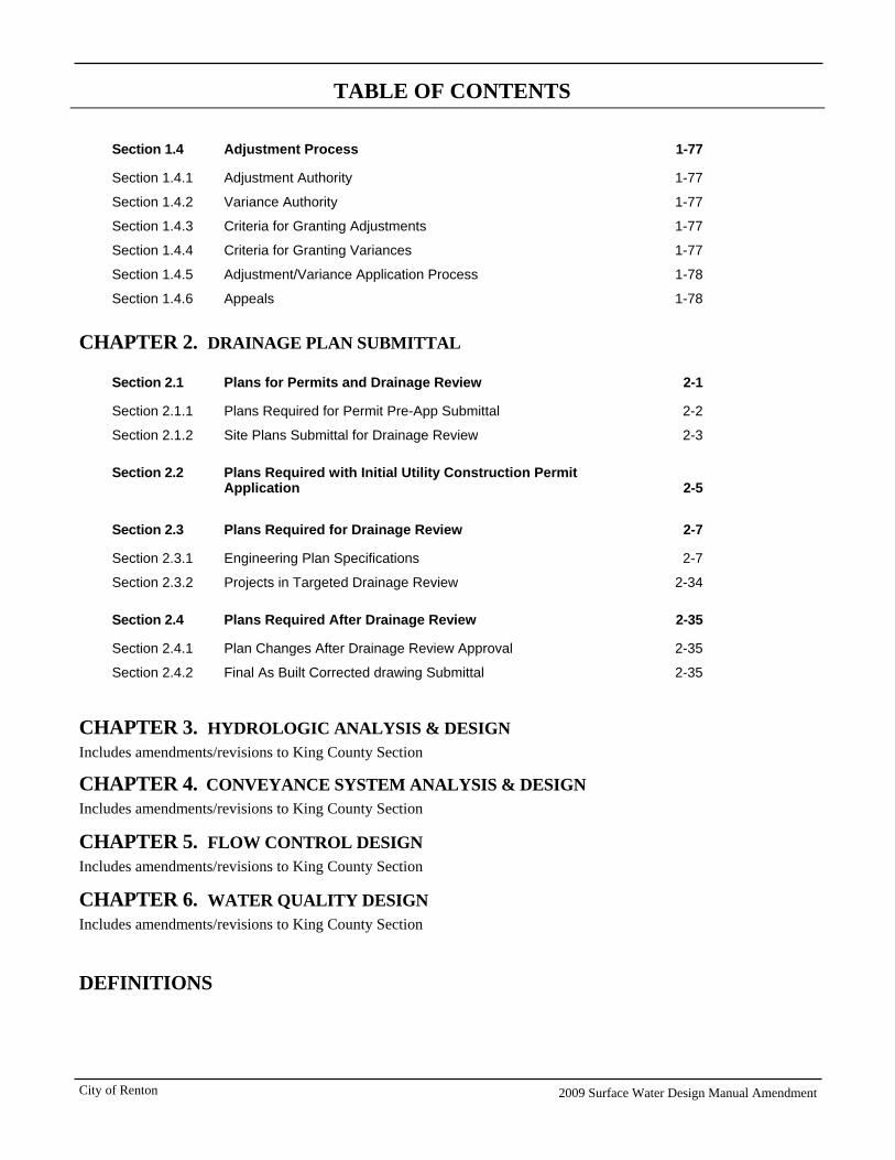
TABLE OF CONTENTS
City of Renton 2009 Surface Water Design Manual Amendment
Section 1.4 Adjustment Process 1-77
Section 1.4.1 Adjustment Authority 1-77
Section 1.4.2 Variance Authority 1-77
Section 1.4.3 Criteria for Granting Adjustments 1-77
Section 1.4.4 Criteria for Granting Variances 1-77
Section 1.4.5 Adjustment/Variance Application Process 1-78
Section 1.4.6 Appeals 1-78
CHAPTER 2. DRAINAGE PLAN SUBMITTAL
Section 2.1 Plans for Permits and Drainage Review 2-1
Section 2.1.1 Plans Required for Permit Pre-App Submittal 2-2
Section 2.1.2 Site Plans Submittal for Drainage Review 2-3
Section 2.2 Plans Required with Initial Utility Construction Permit Application
2-5
Section 2.3 Plans Required for Drainage Review 2-7
Section 2.3.1 Engineering Plan Specifications 2-7
Section 2.3.2 Projects in Targeted Drainage Review 2-34
Section 2.4 Plans Required After Drainage Review 2-35
Section 2.4.1 Plan Changes After Drainage Review Approval 2-35
Section 2.4.2 Final As Built Corrected drawing Submittal 2-35
CHAPTER 3. HYDROLOGIC ANALYSIS & DESIGN Includes amendments/revisions to King County Section
CHAPTER 4. CONVEYANCE SYSTEM ANALYSIS & DESIGN Includes amendments/revisions to King County Section
CHAPTER 5. FLOW CONTROL DESIGN Includes amendments/revisions to King County Section
CHAPTER 6. WATER QUALITY DESIGN Includes amendments/revisions to King County Section
DEFINITIONS
2009 Surface Water Design Manual Amendment City of Renton
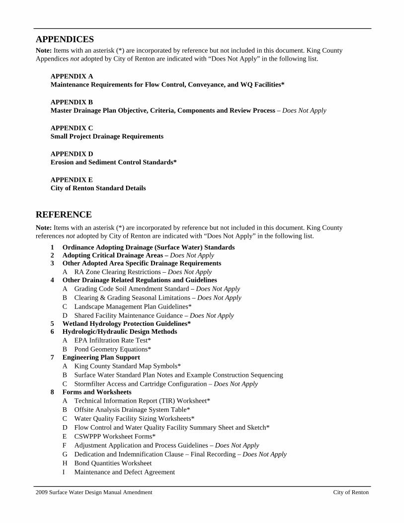
APPENDICES Note: Items with an asterisk (*) are incorporated by reference but not included in this document. King County Appendices not adopted by City of Renton are indicated with “Does Not Apply” in the following list.
APPENDIX A Maintenance Requirements for Flow Control, Conveyance, and WQ Facilities*
APPENDIX B Master Drainage Plan Objective, Criteria, Components and Review Process – Does Not Apply
APPENDIX C Small Project Drainage Requirements
APPENDIX D Erosion and Sediment Control Standards*
APPENDIX E City of Renton Standard Details
REFERENCE Note: Items with an asterisk (*) are incorporated by reference but not included in this document. King County references not adopted by City of Renton are indicated with “Does Not Apply” in the following list.
1 Ordinance Adopting Drainage (Surface Water) Standards 2 Adopting Critical Drainage Areas – Does Not Apply 3 Other Adopted Area Specific Drainage Requirements
A RA Zone Clearing Restrictions – Does Not Apply 4 Other Drainage Related Regulations and Guidelines
A Grading Code Soil Amendment Standard – Does Not Apply B Clearing & Grading Seasonal Limitations – Does Not Apply C Landscape Management Plan Guidelines* D Shared Facility Maintenance Guidance – Does Not Apply
5 Wetland Hydrology Protection Guidelines* 6 Hydrologic/Hydraulic Design Methods
A EPA Infiltration Rate Test* B Pond Geometry Equations*
7 Engineering Plan Support A King County Standard Map Symbols* B Surface Water Standard Plan Notes and Example Construction Sequencing C Stormfilter Access and Cartridge Configuration – Does Not Apply
8 Forms and Worksheets A Technical Information Report (TIR) Worksheet* B Offsite Analysis Drainage System Table* C Water Quality Facility Sizing Worksheets* D Flow Control and Water Quality Facility Summary Sheet and Sketch* E CSWPPP Worksheet Forms* F Adjustment Application and Process Guidelines – Does Not Apply G Dedication and Indemnification Clause – Final Recording – Does Not Apply H Bond Quantities Worksheet I Maintenance and Defect Agreement
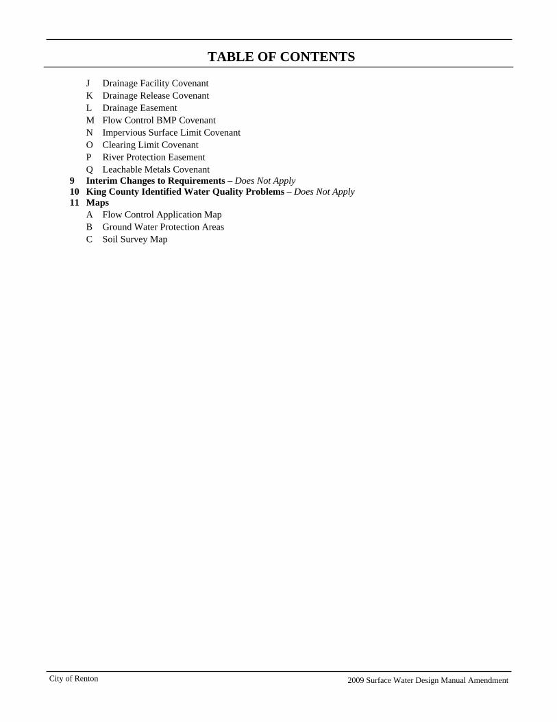
TABLE OF CONTENTS
City of Renton 2009 Surface Water Design Manual Amendment
J Drainage Facility Covenant K Drainage Release Covenant L Drainage Easement M Flow Control BMP Covenant N Impervious Surface Limit Covenant O Clearing Limit Covenant P River Protection Easement Q Leachable Metals Covenant
9 Interim Changes to Requirements – Does Not Apply 10 King County Identified Water Quality Problems – Does Not Apply 11 Maps
A Flow Control Application Map B Ground Water Protection Areas C Soil Survey Map
2009 Surface Water Design Manual Amendment City of Renton i
INTRODUCTION The City of Renton adopts the 2009 King County Surface Water Design Manual (King County Manual) for the design, construction, and maintenance of stormwater management systems and facilities that are approved through the development permit process. Included in the adoption of the King County Manual is this City of Renton Amendments to the 2009 King County Surface Water Design Manual. The Amendment revises Chapters 1 and 2 in their entirety and identifies changes to the remainder of the King County Manual to reflect City of Renton-specific requirements.
Purpose of and Need for this Document The City’s adoption of the King County Manual and accompanying Amendment was the method used by the City to comply with new federal stormwater regulations. Specifically, Phase II of the National Pollutant Discharge Elimination System (NPDES) establishes regulations for jurisdictions that:
1. Own and operate a storm drain system;
2. Discharge to surface waters;
3. Are located in urbanized areas; and
4. Have a population greater than 1,000.
With a 2000 census population of approximately just over 50,052, the City of Renton falls under the jurisdiction of Phase II requirements.
Washington State’s Department of Ecology (Ecology), who oversees stormwater requirements in the state, has developed the 2005 Stormwater Management Manual for Western Washington (Ecology Manual), which complies with the NPDES stormwater discharge requirements. In addition, Ecology has approved the 2009 King County Manual as equivalent to the Ecology Manual.
The new surface water standards outlined in these manuals generally increase flow control requirements, especially for redevelopment projects, and also increase water quality treatment volumes over the previously required standards. The new standards are more protective of receiving waters and will be more aggressive in reducing flooding and minimizing impacts to water quality and aquatic habitat in the City.
How to Use this Amendment This Amendment shall be used in coordination with the 2009 King County Manual for the following:
• To translate specific wording or reference from King County to the City.
• To cross-reference City ordinances and City maps in lieu of King County ordinances and maps.
• To provide a linkage or reference to other City requirements such as more restrictive requirements outlined in the City’s Aquifer Protection Ordinances.
• To provide exceptions, modifications, and additions to the King County Manual.
The King County Manual will be used as outlined in this Amendment. Revisions, modifications, and additions to the King County Manual are organized and referenced by chapter and section in the same manner as the King County Manual. Some global changes will also be applied throughout the entire King County Manual. The applicant shall override the maps and references to other documents as indicated within this Amendment.
The City also adopts by reference a separate document, the 2009 King County Stormwater Pollution Prevention Manual, for determining source control requirements.
City of Renton 2009 Surface Water Design Manual Amendment ii
Amendment Organization This Amendment is organized as follows:
• Introduction: This introduction provides instructions on using the City of Renton’s Amendment in conjunction with the King County Manual. It also defines terms in the King County Manual that are used differently for the City of Renton; City departments and divisions that are equivalent to County departments referred to in the King County Manual; City ordinances that take the place of corresponding County ordinances; and designations from the King County Manual that do not apply to projects in the City of Renton.
• Chapter 1– Drainage Review Requirements: Chapter 1 of the King County Manual is replaced in its entirety.
• Chapter 2 – Drainage Plan Submittal: Chapter 2 of the King County Manual is replaced in its entirety.
• Chapter 3 – Hydrologic Analysis and Design: The City of Renton has made minor changes to Chapter 3 of the King County Manual. This Amendment to Chapter 3 provides replacement text for the sections that are changed. Apart from these changes, Chapter 3 of the King County Manual applies for proposed projects in the City of Renton.
• Chapter 4 – Drainage Plan Submittal: The City of Renton has made minor changes to Chapter 4 of the King County Manual. This Amendment to Chapter 4 provides replacement text for the sections that are changed. Apart from these changes, Chapter 4 of the King County Manual applies for proposed projects in the City of Renton.
• Chapter 5 – Conveyance System Analysis and Design: The City of Renton has made minor changes to Chapter 5 of the King County Manual. This Amendment to Chapter 5 provides replacement text for the sections that are changed. Apart from these changes, Chapter 5 of the King County Manual applies for proposed projects in the City of Renton.
• Chapter 6 – Water Quality Design: The City of Renton has made minor changes to Chapter 6 of the King County Manual. This Amendment to Chapter 6 provides replacement text for the sections that are changed. Apart from these changes, Chapter 6 of the King County Manual applies for proposed projects in the City of Renton.
• Appendices: King County Appendix A to the King County Manual applies to the City of Renton. King County Appendix B to the King County Manual does not apply to the City of Renton. King County Appendix, C to the King County Manual applies, as modified in this Amendment, to proposed projects in the City of Renton. King County Appendix D to the King County Manual applies, to all projects in the City of Renton, with the exception of sections D.8.2 and D.8.3, where the applicant shall refer to reference 7-B as amended by the City. The City is adding Appendix E, City of Renton Standards Details.
• References: Reference Sections 2, 3, 4A, 4B, 4D, 7C, 8F, 8G, 9, and 10 of the King County Manual do not apply to the City of Renton. Reference Sections that apply to the City of Renton Surface Water Design Manual include 4C, 5, 6, 7A, 8A, 8B, 8C, 8D, 8E, and 8P. Reference Sections that are replaced by the City of Renton Surface Water Design Manual include 1, 7B, 8H, 8I, 8J, 8K, 8L, 8M, 8N, 8O, and 8Q. The City is also adding new reference 8P1 and 11.
City Equivalents for County Agencies For proposed projects located within the City of Renton, all references in the King County Manual to the following County departments are to be replaced by reference to the City of Renton Development Services Division (RDSD):
• Department of Development and Environmental Services (DDES)
• Department of Natural Resources and Parks (DNRP)
• Surface Water Management (SWM) Division
• Water and Land Resources (WLR) Division
Unless the context requires otherwise, any reference to “County” or “King County” shall refer to the City of Renton and any reference to County Staff shall refer to the head of RDSD.
2009 Surface Water Design Manual Amendment City of Renton iii
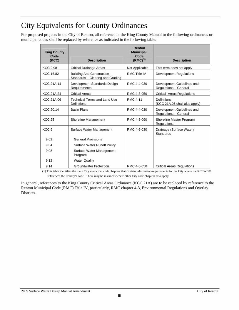
City Equivalents for County Ordinances For proposed projects in the City of Renton, all reference in the King County Manual to the following ordinances or municipal codes shall be replaced by reference as indicated in the following table:
King County Code (KCC) Description
Renton Municipal
Code (RMC)(1) Description
KCC 2.98 Critical Drainage Areas Not Applicable This term does not apply
KCC 16.82 Building And Construction Standards – Clearing and Grading
RMC Title IV Development Regulations
KCC 21A.14 Development Standards Design Requirements
RMC 4-4-030 Development Guidelines and Regulations – General
KCC 21A.24 Critical Areas RMC 4-3-050 Critical Areas Regulations
KCC 21A.06
Technical Terms and Land Use Definitions
RMC 4-11 Definitions (KCC 21A.06 shall also apply)
KCC 20.14 Basin Plans RMC 4-4-030 Development Guidelines and Regulations – General
KCC 25 Shoreline Management RMC 4-3-090 Shoreline Master Program Regulations
KCC 9
9.02
9.04
9.08
9.12
9.14
Surface Water Management
General Provisions
Surface Water Runoff Policy
Surface Water Management Program
Water Quality
Groundwater Protection
RMC 4-6-030
RMC 4-3-050
Drainage (Surface Water) Standards
Critical Areas Regulations
(1) This table identifies the main City municipal code chapters that contain information/requirements for the City where the KCSWDM references the County’s code. There may be instances where other City code chapters also apply.
In general, references to the King County Critical Areas Ordinance (KCC 21A) are to be replaced by reference to the Renton Municipal Code (RMC) Title IV, particularly, RMC chapter 4-3, Environmental Regulations and Overlay Districts.
City of Renton 2009 Surface Water Design Manual Amendment iv
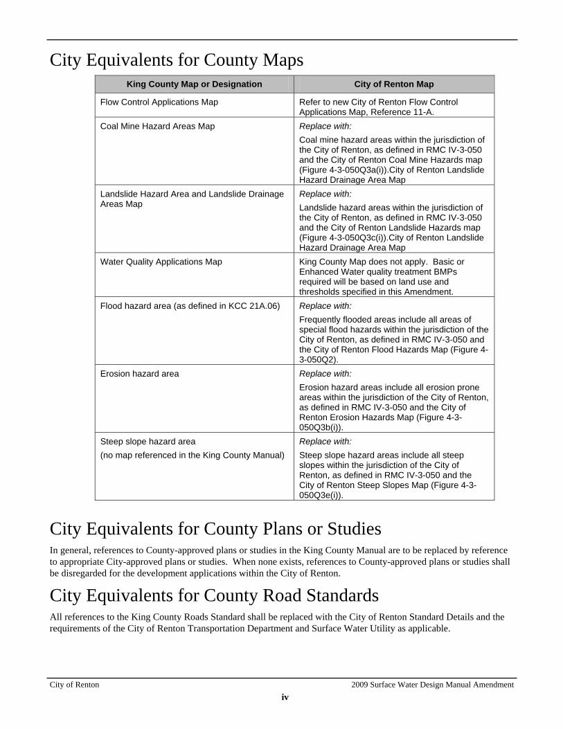
City Equivalents for County Maps King County Map or Designation City of Renton Map
Flow Control Applications Map Refer to new City of Renton Flow Control Applications Map, Reference 11-A.
Coal Mine Hazard Areas Map Replace with: Coal mine hazard areas within the jurisdiction of the City of Renton, as defined in RMC IV-3-050 and the City of Renton Coal Mine Hazards map (Figure 4-3-050Q3a(i)).City of Renton Landslide Hazard Drainage Area Map
Landslide Hazard Area and Landslide Drainage Areas Map
Replace with: Landslide hazard areas within the jurisdiction of the City of Renton, as defined in RMC IV-3-050 and the City of Renton Landslide Hazards map (Figure 4-3-050Q3c(i)).City of Renton Landslide Hazard Drainage Area Map
Water Quality Applications Map King County Map does not apply. Basic or Enhanced Water quality treatment BMPs required will be based on land use and thresholds specified in this Amendment.
Flood hazard area (as defined in KCC 21A.06) Replace with: Frequently flooded areas include all areas of special flood hazards within the jurisdiction of the City of Renton, as defined in RMC IV-3-050 and the City of Renton Flood Hazards Map (Figure 4-3-050Q2).
Erosion hazard area Replace with: Erosion hazard areas include all erosion prone areas within the jurisdiction of the City of Renton, as defined in RMC IV-3-050 and the City of Renton Erosion Hazards Map (Figure 4-3-050Q3b(i)).
Steep slope hazard area (no map referenced in the King County Manual)
Replace with: Steep slope hazard areas include all steep slopes within the jurisdiction of the City of Renton, as defined in RMC IV-3-050 and the City of Renton Steep Slopes Map (Figure 4-3-050Q3e(i)).
City Equivalents for County Plans or Studies In general, references to County-approved plans or studies in the King County Manual are to be replaced by reference to appropriate City-approved plans or studies. When none exists, references to County-approved plans or studies shall be disregarded for the development applications within the City of Renton.
City Equivalents for County Road Standards All references to the King County Roads Standard shall be replaced with the City of Renton Standard Details and the requirements of the City of Renton Transportation Department and Surface Water Utility as applicable.
2009 Surface Water Design Manual Amendment City of Renton v
County Designations that Do not Apply in the City The following designations are used in the King County Manual but are not currently used in the City of Renton; any reference in the King County Manual to the existence of areas with these designation or thresholds or requirements for such areas is to be disregarded for the development applications with the City of Renton:
• Sensitive Lake
• Sphagnum Bog
• Critical Drainage Area
• Forest Production Zone Area
• Rural Residential Development
• Stormwater Compliance Plans (SWCPs)
• Urban Planned Development
Conflicts in Application of King County Manual Modifications to City of Renton Any conflict that arises between the King County Manual and this Amendment shall be interpreted by the City of Renton RDSD. The RDSD will have final decision on all interpretations. In general, this Amendment will take precedence. In addition, if conflicts arise between Chapters 1 and 2 of this Amendment, and other chapters, Chapters 1 and 2 will take precedence.


2009 Surface Water Design Manual Amendment City of Renton
CHAPTER 1 DRAINAGE REVIEW AND REQUIREMENTS
CITY OF RENTON AMENDMENTS TO THE KING COUNTY SURFACE WATER DESIGN MANUAL February 2010
Section 1.1 Drainage Review 1-7
Section 1.1.1 Projects Requiring Drainage Review 1-8
Section 1.1.2 Drainage Review Types and Requirements
1-9
Section 1.1.3 Drainage Review Required By Other Agencies
1-17
Section 1.1.4 Drainage Design Beyond Minimum Compliance
1-17
Section 1.2 Core Requirements 1-19
Section 1.2.1 Core Reqmt #1: Discharge at the Natural Location
1-19
Section 1.2.2 Core Reqmt #2: Offsite Analysis 1-21
Section 1.2.3 Core Reqmt #3: Flow Control 1-28
Section 1.2.4 Core Reqmt #4: Conveyance System
1-46
Section 1.2.5 Core Reqmt #5: Erosion and Sediment Control
1-52
Section 1.2.6 Core Reqmt #6: Maintenance and Operations
1-56
Section 1.2.7 Core Reqmt #7: Financial Guarantees and Liability
1-58
Section 1.2.8 Core Reqmt #8: Water Quality 1-60
Section 1.3 Special Requirements 1-69
Section 1.3.1 Special Reqmt #1: Other Adopted Area-Specific Requirements
1-69
Section 1.3.2 Special Reqmt #2: Flood Hazard Area Delineation
1-71
Section 1.3.3 Special Reqmt #3: Flood Protection Facilities
1-72
Section 1.3.4 Special Reqmt #4: Source Control 1-73
Section 1.3.5 Special Reqmt #5: Oil Control 1-74
Section 1.3.6 Special Reqmt #6: Aquifer Protection Area
1-76
Section 1.4 Adjustment Process 1-77
Section 1.4.1 Adjustment Authority 1-77
Section 1.4.2 Variance Authority 1-77
Section 1.4.3 Criteria for Granting Adjustments 1-77
Section 1.4.4 Criteria for Granting Variances 1-77
Section 1.4.5 Adjustment/Variance Application Process
1-78
Section 1.4.6 Appeals 1-78


2009 Surface Water Design Manual Amendment City of Renton
1-1
CHAPTER 1 DRAINAGE REVIEW AND REQUIREMENTS
This chapter describes the drainage review procedures and types, the drainage requirements, and the adjustment procedures necessary to implement surface water runoff policies codified in Chapter 4-6-030 of the Renton Municipal Code (RMC). It also provides direction for implementing the more detailed procedures and design criteria found in subsequent chapters of this manual.
Chapter Organization The information presented in Chapter 1 is organized into four main sections as follows:
• Section 1.1, "Drainage Review" (p. 1-7)
• Section 1.2, "Core Requirements" (p. 1-19)
• Section 1.3, "Special Requirements" (p. 1-69)
• Section 1.4, "Adjustment Process" (p. 1-77).
Each of these sections begins on an odd page so the user can insert tabs if desired for quicker reference.
Formatting of Chapter Text The text of Chapter 1 and subsequent chapters has been formatted using the following conventions to aid the user in finding, understanding, and properly applying the thresholds, requirements, and procedures contained in this manual:
• Italic is used to highlight the following: (a) terms when they are first introduced and defined within the same paragraph; (b) special notes that supplement or clarify thresholds, requirements, and procedures; (c) sentences considered important for purposes of understanding thresholds, requirements, and procedures; and (d) titles of publications.
• Bold italic is used to highlight terms considered key to understanding and applying drainage review thresholds, requirements, and procedures. These are called "key terms" and are defined below. This convention applies after the key term is defined and does not necessarily apply to tables and figures.
• Bold is used to highlight words and phrases that are not key terms but are considered important to emphasize for purposes of finding and properly applying thresholds, requirements, and procedures.
Key Terms and Definitions Proper application of the drainage review and requirements in this chapter requires an understanding of the following key terms and their definitions. Other key terms may be defined in subsequent chapters. All such key terms are highlighted in bold italic throughout the manual. Other important terms that are not key terms are defined in the text when they are first introduced. These are highlighted in italic when they
CHAPTER 1 DRAINAGE REVIEW AND REQUIREMENTS
City of Renton 2009 Surface Water Design Manual Amendment
1-2
are first introduced but are not highlighted throughout the manual. All terms defined in this chapter are also found in the "Definitions" section of this manual as are other important terms defined throughout the Manual.
Aquifer Protection Area (APA) means the portion of an aquifer within the zone of capture and recharge area for a well or well field owned or operated by the City of Renton as depicted in RMC 4-3-050Q1 Maps, Aquifer Protection.
Construct or modify means to install a new drainage pipe/ditch or make improvements to an existing drainage pipe or ditch, for purposes other than maintenance,1 that either serves to concentrate previously unconcentrated surface and storm water runoff or serves to increase, decrease, or redirect the conveyance of surface and storm water runoff.
Civil engineer means a person licensed by the state of Washington as a professional engineer in civil engineering.
Conveyance system nuisance problem means a flooding or erosion problem that does not constitute a severe flooding problem or severe erosion problem and that results from the overflow of a constructed conveyance system for runoff events less than or equal to a 10-year event. Examples include inundation of a shoulder or lane of a roadway, overflows collecting in yards or pastures, shallow flows across driveways, minor flooding of crawl spaces or unheated garages/outbuildings, and minor erosion.
Erosion hazard area is the critical area designation, defined and regulated in RMC 4-3-050, that is applied to areas underlain by soils that are subject to severe erosion when disturbed. Such areas are delineated on the Erosion Hazards map, Figure 4-3-050Q3b(i) in the RMC.
Existing site conditions means those that existed prior to May 1979 as determined from aerial photographs and, if necessary, knowledge of individuals familiar with the area, unless a drainage plan for land cover changes has been approved by the City of Renton since May 1979 as part of a City permit or approval (or County-approved permit if in an area that has been annexed by the City). If so, existing site conditions are those created by the site improvements and drainage facilities constructed per the approved drainage plan.
Flood hazard area is the critical area designation, defined and regulated in RMC 4-3-050, that is applied to areas that are subject to flooding. Such areas are delineated on the Flood Hazards map, Figure 4-3-050Q2 in the RMC.
Fully dispersed means the runoff from an impervious surface or non-native pervious surface has dispersed per the criteria for fully dispersed surface in Section 1.2.3.2.C (p. 1-41).
Groundwater protection areas include the Cedar Valley Sole Source Aquifer Project Review Area designated by the Environmental Protection Agency, Wellhead Protection Areas as mapped by the Washington State Department of Health, and the Aquifer Protection Area. The combined area described by these criteria is represented in Reference 11-B, Groundwater Protection Areas in the City of Renton.
High-use site means a commercial or industrial site that (1) has an expected average daily traffic (ADT) count equal to or greater than 100 vehicles per 1,000 square feet of gross building area; (2) is subject to petroleum storage or transfer in excess of 1,500 gallons per year, not including delivered heating oil; or (3) is subject to use, storage, or maintenance of a fleet of 25 or more vehicles that are over 10 tons net weight (trucks, buses, trains, heavy equipment, etc.). Also included is any road intersection with a
1 Maintenance means those usual activities taken to prevent a decline, lapse, or cessation in the use of currently serviceable
structures, facilities, equipment, or systems if there is no expansion of the structure, facilities, equipment, or system and there are no significant hydrologic impacts. Maintenance includes the repair or replacement of non-functional facilities and the replacement of existing structures with different types of structures, if the repair or replacement is required to meet current engineering standards or is required by one or more environmental permits and the functioning characteristics of the original facility or structure are not changed. For the purposes of applying this definition to the thresholds and requirements of this manual, RDSD will determine whether the functioning characteristics of the original facility or structure will remain sufficiently unchanged to consider replacement as maintenance.
CHAPTER 1—KEY TERMS AND DEFINITIONS
2009 Surface Water Design Manual Amendment City of Renton
1-3
measured ADT count of 25,000 vehicles or more on the main roadway and 15,000 vehicles or more on any intersecting roadway, excluding projects proposing primarily pedestrian or bicycle use improvements. For the purposes of this definition, commercial and industrial site means that portion of a site's developed area associated with an individual commercial or industrial business (e.g., the area occupied by the business's buildings and required parking).
Historic site conditions means those that existed on the site prior to any development in the Puget Sound region. For lands not currently submerged (i.e., outside the ordinary high water mark of a lake, wetland, or stream), historic site conditions shall be assumed to be forest cover unless reasonable, historic, site-specific information is provided to demonstrate a different vegetation cover. In some stream basins, as allowed per Section 1.2.3.1.B, historic site conditions for lands not currently submerged may be assumed to be 75% forest, 15% grass, and 10% impervious surface.
Land disturbing activity means any activity that results in a change in the existing soil cover, both vegetative and non-vegetative, or the existing soil topography. Land disturbing activities include, but are not limited to demolition, construction, clearing, grading, filling, excavation, and compaction. Land disturbing activity does not include tilling conducted as part of agricultural practices, landscape maintenance, or gardening.
Landslide hazard area is the critical designation, defined and regulated in RMC 4 3 050, that is applied to areas subject to severe risk of landslide due to topography, soil conditions, and geology. Such areas are delineated on the Landslide Hazards map, Figure 4-3-050Q3v(i) in the RMC.
Landslide hazard drainage area means an area that has overland flows from a project and may pose a significant threat to health and safety because of its close proximity to a landslide hazard area.
Major receiving water means a large receiving water that has been determined by City of Renton to be safe for the direct discharge of increased runoff from a proposed project without a flow control facility, subject to the restrictions on such discharges set forth in Core Requirement #3, Section 1.2.3. A list of major receiving waters is provided in Section 1.2.3.1 (p. 1-33). Major receiving waters are also considered safe for application of Basic WQ treatment in place of otherwise required Enhanced Basic WQ treatment (see Section 1.2.8.1).
Native vegetated surface means a surface in which the soil conditions, ground cover, and species of vegetation are like those of the original native condition for the site. More specifically, this means (1) the soil is either undisturbed or has been treated according to the "native vegetated landscape" specifications in Appendix C, Section C.2.1.8; (2) the ground is either naturally covered with vegetation litter or has been top-dressed with 4 inches of hog fuel consistent with the native vegetated landscape specifications in Appendix C; and (3) the vegetation is either (a) comprised predominantly of plant species, other than noxious weeds, that are indigenous to the coastal region of the Pacific Northwest and that reasonably could have been expected to occur naturally on the site or (b) comprised of plant species specified for a native vegetated landscape in Appendix C. Examples of these plant species include trees such as Douglas fir, western hemlock, western red cedar, alder, big-leaf maple and vine maple; shrubs such as willow, elderberry, salmonberry and salal; and herbaceous plants such as sword fern, foam flower, and fireweed.
Natural discharge area means an onsite area tributary to a single natural discharge location.
Natural discharge location means the location where surface and storm water runoff leaves (or would leave if not infiltrated or retained) the site or project site under existing site conditions.
New impervious surface means the addition of a hard or compacted surface like roofs, pavement, gravel, or dirt; or the addition of a more compacted surface, like paving over pre-existing dirt or gravel.
New pervious surface means the conversion of a native vegetated surface or other native surface to a non-native pervious surface (e.g., conversion of forest or meadow to pasture land, grass land, cultivated land, lawn, landscaping, bare soil, etc.), or any alteration of existing non-native pervious surface that significantly increases surface and storm water runoff (e.g., conversion of pasture land, grass land, or cultivated land to lawn, landscaping, or bare soil; or alteration of soil characteristics).
CHAPTER 1 DRAINAGE REVIEW AND REQUIREMENTS
City of Renton 2009 Surface Water Design Manual Amendment
1-4
New PGIS means new impervious surface that is pollution-generating impervious surface.
New PGPS means new pervious surface that is pollution-generating pervious surface.
Pollution-generating impervious surface (PGIS) means an impervious surface considered to be a significant source of pollutants in stormwater runoff. Such surfaces include those that are subject to vehicular use2 or storage of erodible or leachable materials, wastes, or chemicals,3 and that receive direct rainfall or the run-on or blow-in of rainfall.4 Metal roofs are also considered to be PGIS unless they are treated to prevent leaching.
Pollution-generating pervious surface (PGPS) means a non-impervious surface considered to be a significant source of pollutants in surface and storm water runoff. Such surfaces include those subject to use of pesticides and fertilizers, loss of soil, or the use or storage of erodible or leachable materials, wastes, or chemicals. Such surfaces include, but are not limited to, the lawn and landscaped areas of residential or commercial land uses, golf courses, parks, sports fields, and City-standard grassed modular grid pavement.
Project site means that portion of a site and any offsite areas subject to proposed project activities, alterations, and improvements including those required by this manual.
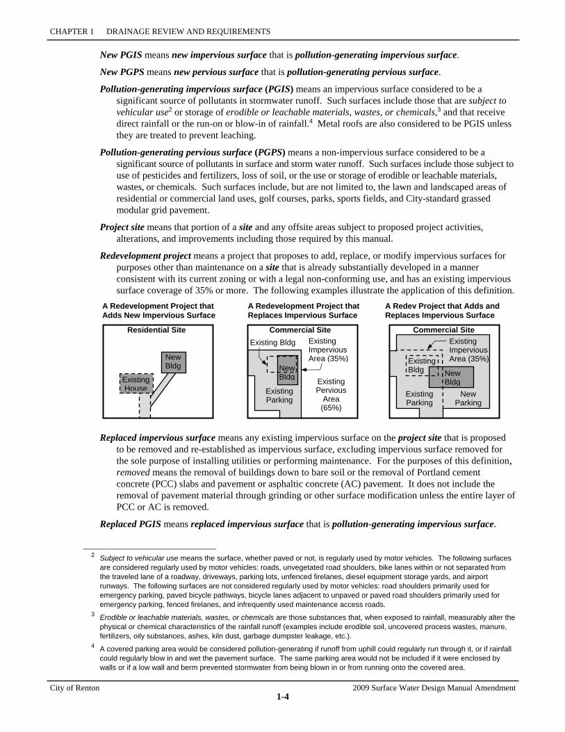
Redevelopment project means a project that proposes to add, replace, or modify impervious surfaces for purposes other than maintenance on a site that is already substantially developed in a manner consistent with its current zoning or with a legal non-conforming use, and has an existing impervious surface coverage of 35% or more. The following examples illustrate the application of this definition.
A Redevelopment Project that Adds New Impervious Surface
A Redevelopment Project that Replaces Impervious Surface
A Redev Project that Adds and Replaces Impervious Surface
Replaced impervious surface means any existing impervious surface on the project site that is proposed to be removed and re-established as impervious surface, excluding impervious surface removed for the sole purpose of installing utilities or performing maintenance. For the purposes of this definition, removed means the removal of buildings down to bare soil or the removal of Portland cement concrete (PCC) slabs and pavement or asphaltic concrete (AC) pavement. It does not include the removal of pavement material through grinding or other surface modification unless the entire layer of PCC or AC is removed.
Replaced PGIS means replaced impervious surface that is pollution-generating impervious surface.
2 Subject to vehicular use means the surface, whether paved or not, is regularly used by motor vehicles. The following surfaces
are considered regularly used by motor vehicles: roads, unvegetated road shoulders, bike lanes within or not separated from the traveled lane of a roadway, driveways, parking lots, unfenced firelanes, diesel equipment storage yards, and airport runways. The following surfaces are not considered regularly used by motor vehicles: road shoulders primarily used for emergency parking, paved bicycle pathways, bicycle lanes adjacent to unpaved or paved road shoulders primarily used for emergency parking, fenced firelanes, and infrequently used maintenance access roads.
3 Erodible or leachable materials, wastes, or chemicals are those substances that, when exposed to rainfall, measurably alter the physical or chemical characteristics of the rainfall runoff (examples include erodible soil, uncovered process wastes, manure, fertilizers, oily substances, ashes, kiln dust, garbage dumpster leakage, etc.).
4 A covered parking area would be considered pollution-generating if runoff from uphill could regularly run through it, or if rainfall could regularly blow in and wet the pavement surface. The same parking area would not be included if it were enclosed by walls or if a low wall and berm prevented stormwater from being blown in or from running onto the covered area.
Existing House Existing
Parking
New Bldg
Existing Parking
New Parking
Existing Pervious
Area (65%)
Existing Impervious Area (35%) Existing
Bldg
Commercial SiteExisting Impervious Area (35%)
Commercial SiteResidential Site
New Bldg
Existing Bldg
New Bldg

CHAPTER 1—KEY TERMS AND DEFINITIONS
2009 Surface Water Design Manual Amendment City of Renton
1-5
Severe building flooding problem means there is flooding of the finished floor area5 of a habitable building,6 or the electrical/heating system of a habitable building for runoff events less than or equal to a 100-year event. Examples include flooding of finished floors of homes and commercial or industrial buildings, or flooding of electrical/heating system components in the crawl space or garage of a home.
Severe erosion problem means there is an open drainage feature with evidence of or potential for erosion/incision sufficient to pose a sedimentation hazard to downstream conveyance systems or pose a landslide hazard by undercutting adjacent slopes. Severe erosion problems do not include roadway shoulder rilling or minor ditch erosion.
Severe flooding problem means a severe building flooding problem or a severe roadway flooding problem.
Severe roadway flooding problem means there is flooding over all lanes of a roadway,7 or a sole access driveway8 is severely impacted, for runoff events less than or equal to the 100-year event. A severely impacted sole access driveway is one in which flooding overtops a culverted section of the driveway, posing a threat of washout or unsafe access conditions due to indiscernible driveway edges, or flooding is deeper than 6 inches on the driveway, posing a severe impediment to emergency access.
Single family residential project means any project that (a) constructs or modifies a single family dwelling unit, (b) makes improvements (e.g., driveways, roads, outbuildings, play courts, etc.) or clears native vegetation on a lot that contains or will contain a single family dwelling unit, or (c) is a plat, short plat, or boundary line adjustment that creates or adjusts lots that will contain single family dwelling units.
Site (a.k.a. development site) means a single parcel, or two or more contiguous parcels that are under common ownership or documented legal control, used as a single parcel for purposes of applying for authority from City of Renton to carry out a development/project proposal. For projects located primarily within dedicated rights-of-way, site includes the entire width of right-of-way within the total length of right-of-way subject to improvements proposed by the project.
Steep slope hazard area is the critical area designation, defined and regulated in RMC 4-3-050, that is applied to areas where extra protection of sensitive slopes is required. (Also refer to the City of Renton Steep Slope Atlas.)
5 Finished floor area, for the purposes of defining severe building flooding problem, means any enclosed area of a building
that is designed to be served by the building's permanent heating or cooling system. 6 Habitable building means any residential, commercial, or industrial building that is equipped with a permanent heating or
cooling system and an electrical system. 7 Roadway, for the purposes of this definition, means the traveled portion of any public or private road or street classified as such
by the City of Renton Standard Details and City of Renton Transportation Department guidelines. 8 Sole access driveway means there is no other unobstructed, flood-free route for emergency access to a habitable building.
CHAPTER 1 DRAINAGE REVIEW AND REQUIREMENTS
City of Renton 2009 Surface Water Design Manual Amendment
1-6
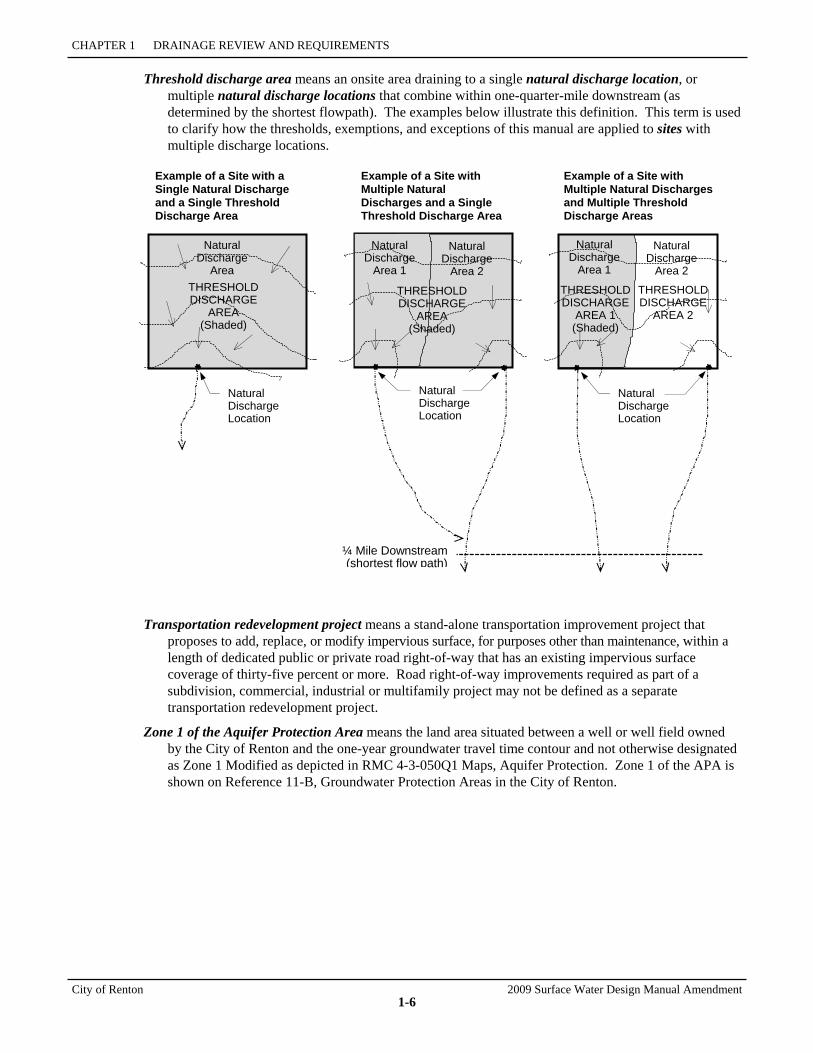
Threshold discharge area means an onsite area draining to a single natural discharge location, or multiple natural discharge locations that combine within one-quarter-mile downstream (as determined by the shortest flowpath). The examples below illustrate this definition. This term is used to clarify how the thresholds, exemptions, and exceptions of this manual are applied to sites with multiple discharge locations.
Example of a Site with a Single Natural Discharge and a Single Threshold Discharge Area
Example of a Site with Multiple Natural Discharges and a Single Threshold Discharge Area
Example of a Site with Multiple Natural Discharges and Multiple Threshold Discharge Areas
Transportation redevelopment project means a stand-alone transportation improvement project that proposes to add, replace, or modify impervious surface, for purposes other than maintenance, within a length of dedicated public or private road right-of-way that has an existing impervious surface coverage of thirty-five percent or more. Road right-of-way improvements required as part of a subdivision, commercial, industrial or multifamily project may not be defined as a separate transportation redevelopment project.
Zone 1 of the Aquifer Protection Area means the land area situated between a well or well field owned by the City of Renton and the one-year groundwater travel time contour and not otherwise designated as Zone 1 Modified as depicted in RMC 4-3-050Q1 Maps, Aquifer Protection. Zone 1 of the APA is shown on Reference 11-B, Groundwater Protection Areas in the City of Renton.
Natural Discharge Location
Natural Discharge
Area 1
Natural Discharge
Area 2
THRESHOLDDISCHARGE
AREA (Shaded)
Natural Discharge
Area 1
Natural Discharge
Area 2
Natural Discharge
Area THRESHOLD DISCHARGE
AREA (Shaded)
THRESHOLD DISCHARGE
AREA 1 (Shaded)
THRESHOLDDISCHARGE
AREA 2
¼ Mile Downstream(shortest flow path)
Natural Discharge Location
Natural Discharge Location
2009 Surface Water Design Manual Amendment City of Renton
1-7
1.1 DRAINAGE REVIEW Drainage review is the evaluation by City of Renton staff of a proposed project's compliance with the drainage requirements of this manual. The City of Renton division responsible for drainage review is the Development Services Division (RDSD) unless otherwise specified in RMC 4-6-060. Drainage review by RDSD is an integral part of its permit review process for development projects. This section describes when and what type of drainage review is required for a proposed project and how to determine which drainage requirements apply.
The section covers the following topics related to drainage review:
• "Projects Requiring Drainage Review," Section 1.1.1 (p. 1-8)
• "Drainage Review Types and Requirements," Section 1.1.2 (p. 1-9)
• "Drainage Review Required By Other Agencies," Section 1.1.3 (p. 1-17)
• "Drainage Design Beyond Minimum Compliance," Section 1.1.4 (p. 1-17)
Guide to Using Section 1.1 The following steps are recommended for efficient use of Section 1.1:
1. Determine whether your proposed project is subject to the requirements of this manual by seeing if it meets any of the thresholds for drainage review specified in Section 1.1.1 (p. 1-8). Making this determination requires an understanding of the key terms defined at the beginning of this chapter.
2. If drainage review is required per Section 1.1.1, use the flow chart in Figure 1.1.2.A (p. 1-10) to determine what type of drainage review will be conducted by RDSD. The type of drainage review defines the scope of drainage requirements that will apply to your project as summarized in Table 1.1.2.A (p. 1-11).
3. Check the more detailed threshold information in Section 1.1.2 (beginning on page 1-9) to verify that you have determined the correct type of drainage review.
4. After verifying the type of drainage review, use the information in Section 1.1.2 to determine which core requirements (found in Section 1.2) and which special requirements (found in Section 1.3) must be evaluated for compliance by your project. To determine how to comply with each applicable core and special requirement, see the more detailed information on these requirements contained in Sections 1.2 and 1.3 of this chapter.
Note: Applicant must attend a pre-application meeting in accordance with Chapter 2. During pre-application meeting, applicant may confirm the type of drainage review and scope of drainage requirements that apply to the proposed project.
SECTION 1.1 DRAINAGE REVIEW
City of Renton 2009 Surface Water Design Manual Amendment
1-8
1.1.1 PROJECTS REQUIRING DRAINAGE REVIEW Drainage review is required for any proposed project (except those proposing only maintenance) that is subject to a City of Renton development permit or approval, including but not limited to those listed at right, AND that meets any one of the following conditions:
1. The project adds or will result in 2,000 square feet9 or more of new impervious surface, replaced impervious surface, or new plus replaced impervious surface, OR
2. The project proposes 7,000 square feet9 or more of land disturbing activity, OR
3. The project proposes to construct or modify a drainage pipe/ditch that is 12 inches or more in size/depth, or receives surface and storm water runoff from a drainage pipe/ditch that is 12 inches or more in size/depth, OR
4. The project contains or is adjacent to a flood hazard area, erosion hazard area, steep slope hazard area, or landslide hazard area as defined in RMC 4-3-050, or projects located within a landslide hazard drainage area, OR
5. The project is a redevelopment project on a single- or multiple-parcel site in which the total of new plus replaced impervious surface is 5,000 square feet or more and whose valuation of proposed improvements (including interior improvements and excluding required mitigation and frontage improvements) exceeds 50% of the assessed value of the existing site improvements.
If drainage review is required for the proposed project, the type of drainage review must be determined based on project and site characteristics as described in Section 1.1.2. The type of drainage review defines the scope of drainage requirements that must be evaluated for compliance with this manual.
9 The thresholds for new impervious surface, replaced impervious surface, and land disturbing activity shall be applied by
project site and in accordance with the definitions of these surfaces and activities. 10 Footnote 10 is not used.
City of Renton Permits and Approvals
Building Permits/Combination Building Permits
Construction Permits Demolitions Permit Flood Control Zone Permits Grading/Filling Permit Land Use Permit Mining, Excavation or Grading permit
or license Planned Urban Development Rezones Right-of-Way Use Application Site Plan Approvals Shoreline Permits Short Subdivision Developments
(Short Plat) Special Permits Subdivision Developments (Plats) Temporary Permits when involving
land disturbance Other City of Renton permits as
required
1.1.2 DRAINAGE REVIEW TYPES AND REQUIREMENTS
2009 Surface Water Design Manual Amendment City of Renton
1-9
1.1.2 DRAINAGE REVIEW TYPES AND REQUIREMENTS For most projects resulting in 2,000 square feet or more of new and/or replaced impervious surface, the full range of core and special requirements contained in Sections 1.2 and 1.3 must be evaluated for compliance through the drainage review process. However, for some types of projects, the scope of requirements applied is narrowed to allow more efficient, customized review. Each of the following four drainage review types tailors the review process and application of drainage requirements to a project's size, location, type of development, and anticipated impacts to the local and regional surface water system:
• Small Project Drainage Review, Section 1.1.2.1 (p. 1-12)
• Targeted Drainage Review, Section 1.1.2.2 (p. 1-13)
• Full Drainage Review, Section 1.1.2.3 (p. 1-15)
• Large Project Drainage Review, Section 1.1.2.4 (p. 1-16).
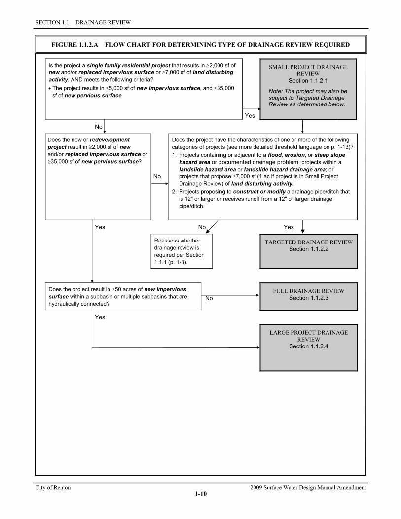
Each project requires only one of the above drainage review types, with the single exception that a project that qualifies for Small Project Drainage Review may also require Targeted Drainage Review. Figure 1.1.2.A (next page) can be used to determine which drainage review type is required. However, this may entail consulting the more detailed thresholds for each review type specified in the above-referenced sections.
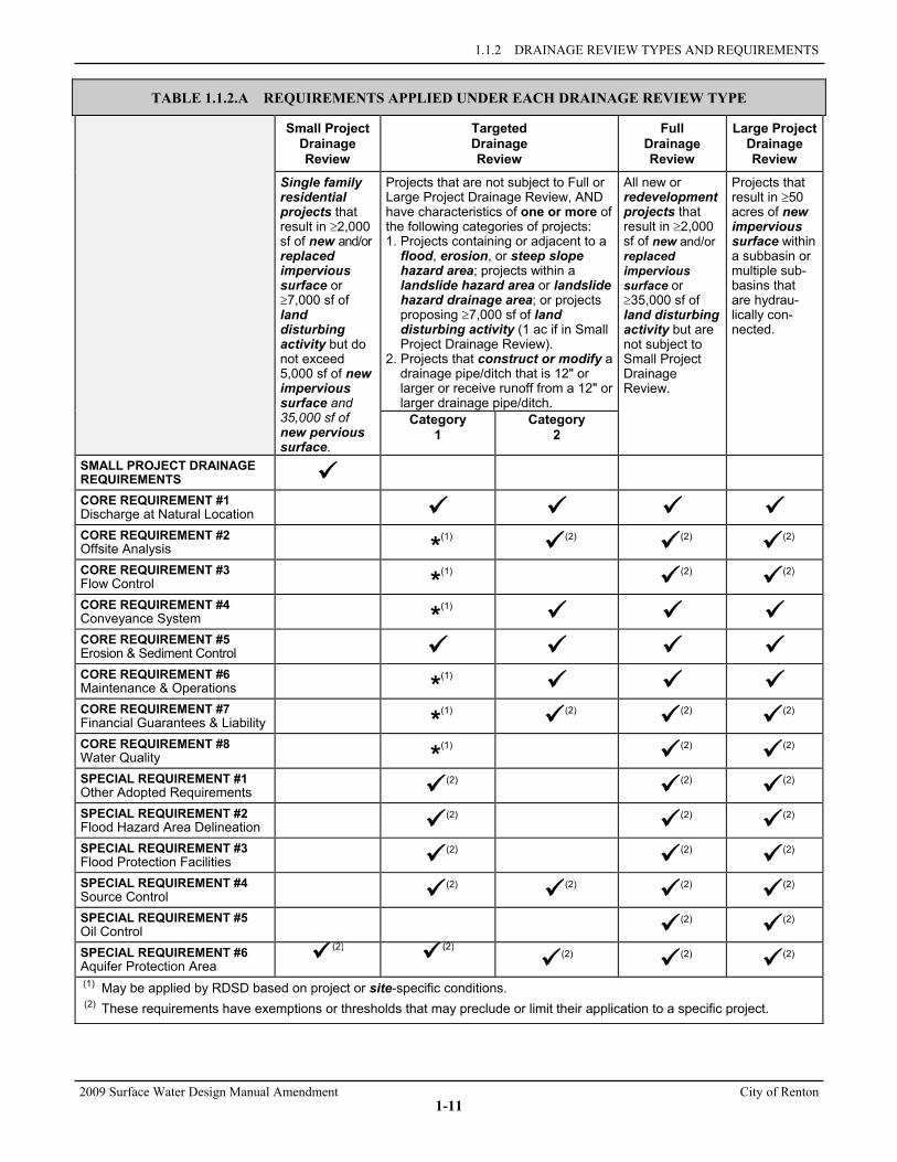
Table 1.1.2.A (p. 1-11) can be used to quickly identify which requirements are applied in each type of drainage review. The applicant must evaluate the requirements "checked" for a particular drainage review type to determine what is necessary for compliance.
SECTION 1.1 DRAINAGE REVIEW
City of Renton 2009 Surface Water Design Manual Amendment
1-10
FIGURE 1.1.2.A FLOW CHART FOR DETERMINING TYPE OF DRAINAGE REVIEW REQUIRED
Is the project a single family residential project that results in ≥2,000 sf of new and/or replaced impervious surface or ≥7,000 sf of land disturbing activity, AND meets the following criteria? • The project results in ≤5,000 sf of new impervious surface, and ≤35,000
sf of new pervious surface
Yes
SMALL PROJECT DRAINAGE REVIEW
Section 1.1.2.1
Note: The project may also be subject to Targeted Drainage Review as determined below.
No
Does the new or redevelopment project result in ≥2,000 sf of new and/or replaced impervious surface or ≥35,000 sf of new pervious surface?
No
Does the project have the characteristics of one or more of the following categories of projects (see more detailed threshold language on p. 1-13)? 1. Projects containing or adjacent to a flood, erosion, or steep slope
hazard area or documented drainage problem; projects within a landslide hazard area or landslide hazard drainage area; or projects that propose ≥7,000 sf (1 ac if project is in Small Project Drainage Review) of land disturbing activity.
2. Projects proposing to construct or modify a drainage pipe/ditch that is 12" or larger or receives runoff from a 12" or larger drainage pipe/ditch.
Yes No Yes
Reassess whether drainage review is required per Section 1.1.1 (p. 1-8).
TARGETED DRAINAGE REVIEW Section 1.1.2.2
Does the project result in ≥50 acres of new impervious surface within a subbasin or multiple subbasins that are hydraulically connected?
No FULL DRAINAGE REVIEW
Section 1.1.2.3
Yes
LARGE PROJECT DRAINAGE REVIEW
Section 1.1.2.4
1.1.2 DRAINAGE REVIEW TYPES AND REQUIREMENTS
2009 Surface Water Design Manual Amendment City of Renton
1-11
TABLE 1.1.2.A REQUIREMENTS APPLIED UNDER EACH DRAINAGE REVIEW TYPE
Small Project Drainage Review
Targeted Drainage Review
Full Drainage Review
Large Project Drainage Review
Single family residential projects that result in ≥2,000 sf of new and/or replaced impervious surface or ≥7,000 sf of land disturbing activity but do not exceed 5,000 sf of new impervious surface and 35,000 sf of new pervious surface.
Projects that are not subject to Full or Large Project Drainage Review, AND have characteristics of one or more of the following categories of projects: 1. Projects containing or adjacent to a
flood, erosion, or steep slope hazard area; projects within a landslide hazard area or landslide hazard drainage area; or projects proposing ≥7,000 sf of land disturbing activity (1 ac if in Small Project Drainage Review).
2. Projects that construct or modify a drainage pipe/ditch that is 12" or larger or receive runoff from a 12" or larger drainage pipe/ditch.
All new or redevelopment projects that result in ≥2,000 sf of new and/or replaced impervious surface or ≥35,000 sf of land disturbing activity but are not subject to Small Project Drainage Review.
Projects that result in ≥50 acres of new impervious surface within a subbasin or multiple sub-basins that are hydrau-lically con-nected.
Category 1
Category 2
SMALL PROJECT DRAINAGE REQUIREMENTS
CORE REQUIREMENT #1 Discharge at Natural Location
CORE REQUIREMENT #2 Offsite Analysis
*(1) (2)
(2) (2)
CORE REQUIREMENT #3 Flow Control
*(1) (2)
(2)
CORE REQUIREMENT #4 Conveyance System
*(1)
CORE REQUIREMENT #5 Erosion & Sediment Control
CORE REQUIREMENT #6 Maintenance & Operations
*(1)
CORE REQUIREMENT #7 Financial Guarantees & Liability
*(1) (2)
(2) (2)
CORE REQUIREMENT #8 Water Quality
*(1) (2)
(2)
SPECIAL REQUIREMENT #1 Other Adopted Requirements
(2) (2)
(2)
SPECIAL REQUIREMENT #2 Flood Hazard Area Delineation
(2) (2)
(2)
SPECIAL REQUIREMENT #3 Flood Protection Facilities
(2) (2)
(2)
SPECIAL REQUIREMENT #4 Source Control
(2) (2)
(2) (2)
SPECIAL REQUIREMENT #5 Oil Control
(2) (2)
SPECIAL REQUIREMENT #6 Aquifer Protection Area
(2)
(2) (2)
(2) (2)
(1) May be applied by RDSD based on project or site-specific conditions. (2) These requirements have exemptions or thresholds that may preclude or limit their application to a specific project.

SECTION 1.1 DRAINAGE REVIEW
City of Renton 2009 Surface Water Design Manual Amendment
1-12
1.1.2.1 SMALL PROJECT DRAINAGE REVIEW Small Project Drainage Review is a simplified drainage review for small residential building, clearing, and subdivision projects that meet the threshold requirements of this section. The core and special requirements applied under Full Drainage Review are replaced with simplified small project drainage requirements that can be applied by a non-engineer. These requirements include simple stormwater dispersion, infiltration, and site design techniques called flow control Best Management Practices (BMPs), which provide the necessary mitigation of flow and water quality impacts for small projects. Also included are simple measures for erosion and sediment control (ESC). This simplified form of drainage review acknowledges that drainage impacts for many small project proposals can be effectively mitigated without construction of costly flow control and water quality facilities.
The Small Project Drainage Review process minimizes the time and effort required to design, submit, review, and approve drainage facilities for these proposals. In most cases, the requirements can be met with submittals prepared by contractors, architects, or homeowners without the involvement of a civil engineer.
Note: some projects subject to Small Project Drainage Review may also require Targeted Drainage Review if they meet any of the threshold criteria in Section 1.1.2.2 (p. 1-13).
Threshold
Small Project Drainage Review is required for any single family residential project that will result in 2,000 square feet or more of new impervious surface, replaced impervious surface, or new plus replaced impervious surface, or 7,000 square feet or more of land disturbing activity and that meets one of the following criteria:
• The project results in ≤5,000 sf of new impervious surface, and ≤35,000 sf of new pervious surface.
Note: for the purposes applying this threshold to a proposed single family residential subdivision (i.e., plat or short plat project), the impervious surface coverage assumed on each created lot shall be 4,000 square feet or the maximum allowed by the RMC 4-6-030, whichever is less. A lower impervious surface coverage may be assumed for any lot in which the lower impervious surface coverage is set as the maximum through a declaration of covenant recorded for the lot. Also, the new pervious surface assumed on each created lot shall be the entire lot area, except the assumed impervious portion and any portion in which native conditions are preserved by a clearing limit per RMC IV, a covenant or easement recorded for the lot, or a tract dedicated by the proposed subdivision.
Scope of Requirements IF Small Project Drainage Review is required, THEN the proposed project must comply with the simplified small project submittal and drainage design requirements detailed in Small Project Drainage Requirements adopted as Appendix C of the 2009 King County Manual. These requirements include simplified BMPs/measures for flow control and erosion and sediment control.
Presumption of Compliance with Core and Special Requirements The simplified drainage requirements applied under Small Project Drainage Review are considered sufficient to meet the overall intent of the core and special requirements in Sections 1.2 and 1.3, except under certain conditions when a proposed project has characteristics that trigger Targeted Drainage Review (see the threshold for Targeted Drainage Review in Section 1.1.2.2, p. 1-13) and may require the involvement of a civil engineer. Therefore, any proposed project that is subject to Small Project Drainage Review as determined above and complies with the small project drainage requirements detailed in Appendix C is presumed to comply with all the core and special requirements in Sections 1.2 and 1.3 except those requirements that would apply to the project if it is subject to Targeted Drainage Review as specified in Section 1.1.2.2 (p. 1-13).
R E Q M T S
T H R E S H O L D
1.1.2 DRAINAGE REVIEW TYPES AND REQUIREMENTS
2009 Surface Water Design Manual Amendment City of Renton
1-13
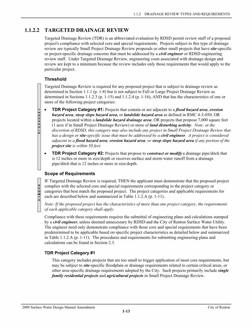
1.1.2.2 TARGETED DRAINAGE REVIEW Targeted Drainage Review (TDR) is an abbreviated evaluation by RDSD permit review staff of a proposed project's compliance with selected core and special requirements. Projects subject to this type of drainage review are typically Small Project Drainage Review proposals or other small projects that have site-specific or project-specific drainage concerns that must be addressed by a civil engineer or RDSD engineering review staff. Under Targeted Drainage Review, engineering costs associated with drainage design and review are kept to a minimum because the review includes only those requirements that would apply to the particular project.
Threshold Targeted Drainage Review is required for any proposed project that is subject to drainage review as determined in Section 1.1.1 (p. 1-8) but is not subject to Full or Large Project Drainage Review as determined in Sections 1.1.2.3 (p. 1-15) and 1.1.2.4 (p. 1-16), AND that has the characteristics of one or more of the following project categories:
• TDR Project Category #1: Projects that contain or are adjacent to a flood hazard area, erosion hazard area, steep slope hazard area, or landslide hazard area as defined in RMC 4-3-050; OR projects located within a landslide hazard drainage area; OR projects that propose 7,000 square feet (1 acre if in Small Project Drainage Review) or more of land disturbing activity. Note: at the discretion of RDSD, this category may also include any project in Small Project Drainage Review that has a design or site-specific issue that must be addressed by a civil engineer. A project is considered adjacent to a flood hazard area, erosion hazard area, or steep slope hazard area if any portion of the project site is within 50 feet.
• TDR Project Category #2: Projects that propose to construct or modify a drainage pipe/ditch that is 12 inches or more in size/depth or receives surface and storm water runoff from a drainage pipe/ditch that is 12 inches or more in size/depth.
Scope of Requirements IF Targeted Drainage Review is required, THEN the applicant must demonstrate that the proposed project complies with the selected core and special requirements corresponding to the project category or categories that best match the proposed project. The project categories and applicable requirements for each are described below and summarized in Table 1.1.2.A (p. 1-11).
Note: If the proposed project has the characteristics of more than one project category, the requirements of each applicable category shall apply.
Compliance with these requirements requires the submittal of engineering plans and calculations stamped by a civil engineer, unless deemed unnecessary by RDSD and the City of Renton Surface Water Utility. The engineer need only demonstrate compliance with those core and special requirements that have been predetermined to be applicable based on specific project characteristics as detailed below and summarized in Table 1.1.2.A (p. 1-11). The procedures and requirements for submitting engineering plans and calculations can be found in Section 2.3.
TDR Project Category #1 This category includes projects that are too small to trigger application of most core requirements, but may be subject to site-specific floodplain or drainage requirements related to certain critical areas, or other area-specific drainage requirements adopted by the City. Such projects primarily include single family residential projects and agricultural projects in Small Project Drainage Review.
R E Q M T S
T H R E S H O L D
SECTION 1.1 DRAINAGE REVIEW
City of Renton 2009 Surface Water Design Manual Amendment
1-14
IF the proposed project meets the characteristics of TDR Project Category #1, THEN the applicant must demonstrate that the project complies with the following requirements:
• Core Requirement #1: Discharge at the Natural Location, Section 1.2.1 (p. 1-19)
• Core Requirement #5: Erosion and Sediment Control, Section 1.2.5 (p. 1-52)
• Special Requirement #1: Other Adopted Area-Specific Requirements, Section 1.3.1 (p. 1-69)
• Special Requirement #2: Floodplain/Floodway Analysis, Section 1.3.2 (p. 1-71)
• Special Requirement #3: Flood Protection Facilities, Section 1.3.3 (p. 1-72)
• Special Requirement #4: Source Control, Section 1.3.4 (p. 1-73)
• Special Requirement #6: Aquifer Protection Area, Section 1.3.6 (p. 1-76)
In addition, RDSD may require the applicant to demonstrate compliance with any one or more of the remaining seven core requirements in Section 1.2 based on project or site-specific conditions. For example, if the proposed project discharges to an erosion or steep slope hazard area as defined in RMC 4-3-050, RDSD may require compliance with "Core Requirement #1: Discharge at the Natural Location" (Section 1.2.1, p. 1-19). This may in turn require compliance with "Core Requirement #2: Offsite Analysis" (Section 1.2.2, p. 1-21) if a tightline is required by Core Requirement #1. If a tightline is found to be infeasible, RDSD may instead require a flow control facility per "Core Requirement #3: Flow Control" (Section 1.2.3, p. 1-28). If a tightline is feasible, "Core Requirement #4: Conveyance System" (Section 1.2.4, p. 1-46) would be required to ensure proper size and design. Any required flow control facility or tightline system may also trigger compliance with "Core Requirement #6: Maintenance and Operations" (Section 1.2.6, p. 1-56), "Core Requirement #7: Financial Guarantees and Liability" (Section 1.2.7, p. 1-58), and possibly "Core Requirement #8: Water Quality" (Section 1.2.8, p. 1-60) if runoff from pollution-generating impervious surfaces is collected.
The applicant may also need to address compliance with any applicable critical areas requirements in RMC 4-3-050 as determined by RDSD.
TDR Project Category #2 This category is intended to apply selected core and special requirements to those projects that propose to construct or modify a drainage system of specified size, but are not adding sufficient impervious surface to trigger Full Drainage Review or Large Project Drainage Review.
IF the proposed project meets the characteristics of TDR Project Category #2, THEN the applicant must demonstrate that the proposed project complies with the following requirements:
• Core Requirement #1: Discharge at the Natural Location, Section 1.2.1 (p. 1-19)
• Core Requirement #2: Offsite Analysis, Section 1.2.2 (p. 1-21)
• Core Requirement #4: Conveyance System, Section 1.2.4 (p. 1-46)
• Core Requirement #5: Erosion and Sediment Control, Section 1.2.5 (p. 1-52)
• Core Requirement #6: Maintenance and Operations, Section 1.2.6 (p. 1-56)
• Core Requirement #7: Financial Guarantees and Liability, Section 1.2.7 (p. 1-58)
• Special Requirement #4: Source Control, Section 1.3.4 (p. 1-73)
• Special Requirement #6: Aquifer Protection Area, Section 1.3.6 (p. 1-76)
R E Q U I R E M E N T S
R E Q U I R E M E N T S
1.1.2 DRAINAGE REVIEW TYPES AND REQUIREMENTS
2009 Surface Water Design Manual Amendment City of Renton
1-15
1.1.2.3 FULL DRAINAGE REVIEW Full Drainage Review is the evaluation by City staff (RDSD unless otherwise specified in RMC 4-6-060) of a proposed project's compliance with the full range of core and special requirements in this chapter. This review addresses the impacts associated with changing land cover on typical sites.
Threshold Full Drainage Review is required for any proposed project, including a redevelopment project, that is subject to drainage review as determined in Section 1.1.1 (p. 1-8), AND that meets one or more of the following criteria:
• The project including redevelopment project will result in 2000 square feet 11 or more of new impervious surface, replaced impervious surface, and new plus replaced impervious surface but is not subject to Small Project Drainage Review as determined in Section 1.1.2.1 (p. 1-12), OR
• The project will result in 7,000 square feet11 or more of land disturbing activity but is not subject to Small Project Drainage Review per Section 1.1.2.1.
Scope of Requirements IF Full Drainage Review is required, THEN the applicant must demonstrate that the proposed project complies with the following requirements:
• All eight core requirements in Section 1.2
• All six special requirements in Section 1.3
Engineering plans and calculations stamped by a civil engineer must be submitted to demonstrate compliance with these requirements. The procedures and requirements for submittal of engineering plans and calculations are found in Section 2.3.
11 The thresholds of 2,000 and 7,000 square feet shall be applied by project site.
T H R E S H O L D
R E Q M T S
SECTION 1.1 DRAINAGE REVIEW
City of Renton 2009 Surface Water Design Manual Amendment
1-16
1.1.2.4 LARGE PROJECT DRAINAGE REVIEW Large Project Drainage Review is applied to development proposals that are large and/or involve resources or problems of special sensitivity or complexity. Because of the large size and complexities involved, there is usually a greater risk of significant impact or irreparable damage to sensitive resources. Such proposals often require a more definitive approach to drainage requirements than that prescribed by the core and special requirements in Sections 1.2 and 1.3; it may be appropriate to collect additional information about site resources, use more sophisticated models, and prepare special studies not specified in this manual. Large Project Drainage Review entails preparation of a master drainage plan (MDP) or limited scope MDP that is reviewed and approved by RDSD.
Threshold Large Project Drainage Review is required for any proposed project that is subject to drainage review as determined in Section 1.1.1 (p. 1-8), AND the project would, at full buildout, result in 50 acres or more of new impervious surface within a single subbasin or multiple subbasins that are hydraulically connected across subbasin boundaries. Hydraulically connected means connected through surface flow or water features such as wetlands or lakes.
Scope of Requirements IF Large Project Drainage Review is required, THEN the applicant must do the following:
1. Prepare a MDP, limited scope MDP, or special study in accordance with the process and requirements described in the MDP guidelines, Master Drainage Planning for Large or Complex Site Developments, available from RDSD. The MDP or special study shall be completed, or a schedule for completion identified and agreed to by RDSD, prior to permit approval. Note: Generally, it is most efficient for the MDP process to parallel the state Environmental Policy Act (SEPA) process.
2. Demonstrate that the proposed project complies with all the core and special requirements in Sections 1.2 and 1.3, with some potential modifications as follows:
• Core Requirement #2, Offsite Analysis, is typically modified during MDP scoping.
• Core Requirement #3, Flow Control, may be modified to require more sophisticated hydrologic modeling.
• Core Requirement #5, ESC, may be modified to require enhanced construction monitoring.
• Core Requirement #7, Financial Guarantees and Liability, may be modified to implement a monitoring fund.
• Special pre- and post-development monitoring may also be required if deemed necessary by RDSD to adequately characterize sensitive site and downstream resources, and to ensure that onsite drainage controls and mitigation measures are effective in protecting sensitive or critical resources. Detailed guidelines for monitoring are appended to the MDP guidelines referenced above.
R E Q U I R E M E N T S
T H R E S H O L D
1.1.3 DRAINAGE REVIEW REQUIRED BY OTHER AGENCIES
2009 Surface Water Design Manual Amendment City of Renton
1-17
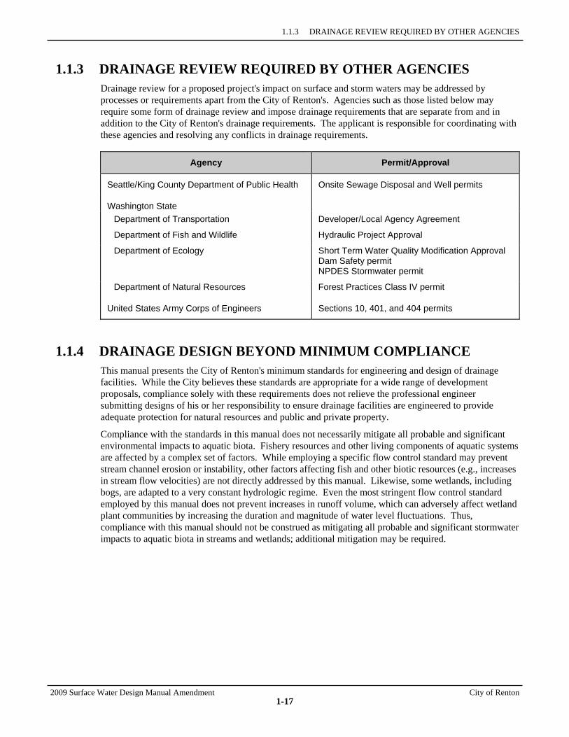
1.1.3 DRAINAGE REVIEW REQUIRED BY OTHER AGENCIES Drainage review for a proposed project's impact on surface and storm waters may be addressed by processes or requirements apart from the City of Renton's. Agencies such as those listed below may require some form of drainage review and impose drainage requirements that are separate from and in addition to the City of Renton's drainage requirements. The applicant is responsible for coordinating with these agencies and resolving any conflicts in drainage requirements.
Agency Permit/Approval
Seattle/King County Department of Public Health Onsite Sewage Disposal and Well permits
Washington State
Department of Transportation Developer/Local Agency Agreement
Department of Fish and Wildlife Hydraulic Project Approval
Department of Ecology Short Term Water Quality Modification Approval Dam Safety permit NPDES Stormwater permit
Department of Natural Resources Forest Practices Class IV permit
United States Army Corps of Engineers Sections 10, 401, and 404 permits
1.1.4 DRAINAGE DESIGN BEYOND MINIMUM COMPLIANCE This manual presents the City of Renton's minimum standards for engineering and design of drainage facilities. While the City believes these standards are appropriate for a wide range of development proposals, compliance solely with these requirements does not relieve the professional engineer submitting designs of his or her responsibility to ensure drainage facilities are engineered to provide adequate protection for natural resources and public and private property.
Compliance with the standards in this manual does not necessarily mitigate all probable and significant environmental impacts to aquatic biota. Fishery resources and other living components of aquatic systems are affected by a complex set of factors. While employing a specific flow control standard may prevent stream channel erosion or instability, other factors affecting fish and other biotic resources (e.g., increases in stream flow velocities) are not directly addressed by this manual. Likewise, some wetlands, including bogs, are adapted to a very constant hydrologic regime. Even the most stringent flow control standard employed by this manual does not prevent increases in runoff volume, which can adversely affect wetland plant communities by increasing the duration and magnitude of water level fluctuations. Thus, compliance with this manual should not be construed as mitigating all probable and significant stormwater impacts to aquatic biota in streams and wetlands; additional mitigation may be required.

2009 Surface Water Design Manual Amendment City of Renton
1-19
1.2 CORE REQUIREMENTS This section details the following eight core requirements:
• "Core Requirement #1: Discharge at the Natural Location," Section 1.2.1
• "Core Requirement #2: Offsite Analysis," Section 1.2.2 (p. 1-21)
• "Core Requirement #3: Flow Control," Section 1.2.3 (p. 1-28)
• "Core Requirement #4: Conveyance System," Section 1.2.4 (p. 1-46)
• "Core Requirement #5: Erosion and Sediment Control," Section 1.2.5 (p. 1-52)
• "Core Requirement #6: Maintenance and Operations," Section 1.2.6 (p. 1-56)
• "Core Requirement #7: Financial Guarantees and Liability," Section 1.2.7 (p. 1-58)
• "Core Requirement #8: Water Quality," Section 1.2.8 (p. 1-60).
1.2.1 CORE REQUIREMENT #1: DISCHARGE AT THE NATURAL LOCATION All surface and storm water runoff from a project must be discharged at the natural location so as not to be diverted onto or away from downstream properties. The manner in which runoff is discharged from the project site must not create a significant adverse impact to downhill properties or drainage systems (see "Discharge Requirements" below). Note: Projects that do not discharge all project site runoff at the natural location will require an approved adjustment of this requirement (see Section 1.4). RDSD may waive this adjustment, however, for projects in which only a small portion of the project site does not discharge runoff at the natural location and the runoff from that portion is unconcentrated and poses no significant adverse impact to downstream properties.
Intent: To prevent adverse impacts to downstream properties caused by diversion of flow from one flowpath to another, and to discharge in a manner that does not significantly impact downhill properties or drainage systems. Diversions can cause greater impacts (from greater runoff volumes) than would otherwise occur from new development discharging runoff at the natural location. Diversions can also impact properties that rely on runoff water to replenish wells and ornamental or fish ponds.
DISCHARGE REQUIREMENTS Proposed projects must comply with the following discharge requirements (1, 2, and 3) as applicable:
1. Where no conveyance system exists at the abutting downstream property line and the natural (existing) discharge is unconcentrated, any runoff concentrated by the proposed project must be discharged as follows:
a) IF the 100-year peak discharge12 is less than or equal to 0.2 cfs under existing conditions and will remain less than or equal to 0.2 cfs under developed conditions, THEN the concentrated runoff may be discharged onto a rock pad or to any other system that serves to disperse flows.
b) IF the 100-year peak discharge is less than or equal to 0.5 cfs under existing conditions and will remain less than or equal to 0.5 cfs under developed conditions, THEN the concentrated runoff may be discharged through a dispersal trench or other dispersal system provided the applicant can demonstrate that there will be no significant adverse impact to downhill properties or drainage systems.
12 Peak discharges for applying this requirement are determined using KCRTS with 15-minute time steps as detailed in Chapter 3.
R E Q U I R E M E N T
SECTION 1.2 CORE REQUIREMENTS
City of Renton 2009 Surface Water Design Manual Amendment
1-20
c) IF the 100-year peak discharge is greater than 0.5 cfs for either existing or developed conditions, or if a significant adverse impact to downhill properties or drainage systems is likely, THEN a conveyance system must be provided to convey the concentrated runoff across the downstream properties to an acceptable discharge point.13 Drainage easements for this conveyance system must be secured from downstream property owners and recorded prior to engineering plan approval.
2. IF a proposed project, or any natural discharge area within a project, is located within a Landslide Hazard Drainage Area and drains over the erodible soils of a landslide hazard area with slopes steeper than 15%, THEN a tightline system must be provided through the landslide hazard area to an acceptable discharge point unless one of the following exceptions applies. The tightline system must comply with the design requirements in Core Requirement #4 and in Section 4.2.2 unless otherwise approved by RDSD. Drainage easements for this system must be secured from downstream property owners and recorded prior to engineering plan approval.
Exceptions: A tightline is not required for any natural discharge location where one of the following conditions can be met:
a) Less than 2,000 square feet of new impervious surface will be added within the natural discharge area, OR
b) The developed conditions runoff from the natural discharge area is less than 0.1 cfs for the 100-year runoff event and will be infiltrated for runoff events up to and including the 100-year event, OR
c) The developed conditions runoff volume14 from the natural discharge area is less than 50% of the existing conditions runoff volume from other areas draining to the location where runoff from the natural discharge area enters the landslide hazard area onto slopes steeper than 15%, AND the provisions of Discharge Requirement 1 are met, OR
d) RDSD determines that a tightline system is not physically feasible or will create a significant adverse impact based on a soils report by a geotechnical engineer.
3. For projects adjacent to or containing a landslide, steep slope, or erosion hazard area as defined in RMC 4-3-050, the applicant must demonstrate that onsite drainage facilities and/or flow control BMPs will not create a significant adverse impact to downhill properties or drainage systems.
13 Acceptable discharge point means an enclosed drainage system (i.e., pipe system, culvert, or tightline) or open drainage
feature (e.g., ditch, channel, swale, stream, river, pond, lake, or wetland) where concentrated runoff can be discharged without creating a significant adverse impact.
14 For the purposes of applying this exception, the developed conditions runoff volume is the average annual runoff volume as computed with KCRTS per Chapter 3. Any areas assumed not to be cleared when computing the developed conditions runoff volume must be set aside in an open space tract or covenant in order for the proposed project to qualify for this exception. Preservation of existing forested areas in Landslide Hazard Drainage Areas is encouraged.
1.2.2 CORE REQUIREMENT #2: OFFSITE ANALYSIS
2009 Surface Water Design Manual Amendment City of Renton
1-21
1.2.2 CORE REQUIREMENT #2: OFFSITE ANALYSIS All proposed projects must submit an offsite analysis report that assesses potential offsite drainage and water quality impacts associated with development of the project site and proposes appropriate mitigation of those impacts. The initial permit submittal shall include, at minimum, a Level 1 downstream analysis as described in Section 1.2.2.1 below. If impacts are identified, the proposed projects shall meet any applicable problem-specific requirements specified in Section 1.2.2.2 (p. 1-24) for mitigation of impacts to drainage problems and Section 1.2.2.3 (p. 1-27) for mitigation of impacts to water quality problems.
Intent: To identify and evaluate offsite flooding, erosion, and water quality problems that may be created or aggravated by the proposed project, and to ensure appropriate measures are provided for preventing creation or aggravation of those problems. In addition, this requirement is intended to ensure appropriate provisions are made, as needed, to mitigate other identified impacts associated with the quantity and quality of surface and storm water runoff from the project site (e.g., impacts to the hydrology of a wetland as may be identified by a "critical area report" per RMC 4-3-050).
The primary component of an offsite analysis report is the downstream analysis, which examines the drainage system within one-quarter mile downstream of the project site or farther as described in Section 1.2.2.1 below. It is intended to identify existing or potential/predictable downstream flooding, erosion, and water quality problems so that appropriate mitigation, as specified in Sections 1.2.2.2 and 1.2.2.3, can be provided to prevent aggravation of these problems. A secondary component of the offsite analysis report is an evaluation of the upstream drainage system to verify and document that significant flooding and erosion impacts will not occur as a result of the proposed project. The evaluation must extend upstream to a point where any backwater effects created by the project cease.
EXEMPTION FROM CORE REQUIREMENT #2 A proposed project is exempt from Core Requirement #2 if any one of the following is true:
1. RDSD together with the City of Renton Surface Water Utility determine there is sufficient information for them to conclude that the proposed project will not have significant adverse impact on the downstream and/or upstream drainage system, OR
2. The project adds less than 2,000 square feet of new impervious surface, AND less than 35,000 square feet of new pervious surface, AND does not construct or modify a drainage pipe/ditch that is 12 inches or more in size/depth or that receives runoff from a drainage pipe/ditch that is 12 inches or more in size/depth, AND does not contain or lie adjacent to a landslide, steep slope, or erosion hazard area as defined in RMC 4-3-050, OR
3. The project does not change the rate, volume, duration, or location of discharges to and from the project site (e.g., where existing impervious surface is replaced with other impervious surface having similar runoff-generating characteristics, or where pipe/ditch modifications do not change existing discharge characteristics).
1.2.2.1 DOWNSTREAM ANALYSIS The level of downstream analysis required depends on specific site and downstream conditions. Each project submittal must include at least a Level 1 downstream analysis. Upon review of the Level 1 analysis, RDSD may require a Level 2 or Level 3 analysis. If conditions warrant, additional, more detailed analysis may be required.
The Level 1 downstream analysis is a qualitative survey of each downstream system and is the first step in identifying flooding or erosion problems as described below under "Downstream Drainage Problems Requiring Special Attention." The Level 1 analysis also identifies water quality problems as described below under "Downstream Water Quality Problems Requiring Special Attention." Each Level 1 analysis is composed of four tasks at a minimum:
R E Q M T
SECTION 1.2 CORE REQUIREMENTS
City of Renton 2009 Surface Water Design Manual Amendment
1-22
• Task 1: Define and map the study area
• Task 2: Review all available information on the study area
• Task 3: Field inspect the study area
• Task 4: Describe the drainage system, and its existing and predicted drainage and water quality problems.
Upon review of the Level 1 analysis, RDSD may require a Level 2 or 3 downstream analysis, depending on the presence of existing or predicted flooding, erosion, or nuisance problems identified in the Level 1 analysis.
Levels 2 and 3 downstream analysis quantify downstream flooding, erosion, or nuisance problems by providing information on the severity and frequency of an existing problem or the likelihood of creating a new problem. A Level 2 analysis is a rough quantitative analysis (non-survey field data, uniform flow analysis). Level 3 is a more precise analysis (e.g., survey field data, backwater analysis) of significant problems. If conditions warrant, additional, more detailed analysis may be required beyond Level 3. For Levels 2 and 3 downstream analysis, an additional Task 5, addressing mitigation of existing and potential flooding, erosion, or nuisance problems, will be required.
Extent of Downstream Analysis The downstream analysis must consider the existing conveyance system(s) for a minimum flowpath distance downstream of one-quarter mile and beyond that, as needed, to reach a point where the project site area constitutes less than 15% of the tributary area. This minimum distance may be increased as follows:
• Task 2 of a Level 1 downstream analysis (described in detail in Section 2.3.1.1) is a review of all available information on the downstream area and is intended to identify existing drainage and water quality problems. In all cases, this information review shall extend one mile downstream of the project site. The existence of flooding or erosion problems further downstream may extend the one-quarter-mile/15% minimum distance for other tasks to allow evaluation of impacts from the proposed development upon the identified flooding or erosion problems. The existence of documented water quality problems beyond the one-quarter-mile/15% distance may in some cases require additional mitigation of impacts as determined necessary by RDSD based on the type and severity of problem.
• If a project's impacts to flooding or erosion problems are mitigated by improvements to the downstream conveyance system, the downstream analysis will extend a minimum of one-quarter mile beyond the improvement. This is necessary because many such improvements result in a reduction of stormwater storage or an increase in peak flows from the problem location.
• At their discretion, RDSD may extend the downstream analysis beyond the minimum distance specified above on the reasonable expectation of drainage or water quality impacts.
A detailed description of the scope of offsite analysis and submittal requirements is provided in Section 2.3.1.1. Hydrologic analysis methods and requirements for Levels 2 and 3 downstream analysis are contained in Chapter 3; hydraulic analysis methods are contained in Chapter 4.
DOWNSTREAM DRAINAGE PROBLEMS REQUIRING SPECIAL ATTENTION While the area-specific flow control facility requirement in Core Requirement #3 (Section 1.2.3.1) serves to minimize the creation and aggravation of many types of downstream drainage problems, there are some types that are more sensitive to creation/aggravation than others depending on the nature or severity of the problem and which flow control facility standard is being applied. In particular, there are three types of downstream drainage problems for which the City has determined that the nature and/or severity of the problem warrants additional attention through the downstream analysis and possibly additional mitigation to ensure no creation/aggravation:
1.2.2 CORE REQUIREMENT #2: OFFSITE ANALYSIS
2009 Surface Water Design Manual Amendment City of Renton
1-23
1. Conveyance system nuisance problem
2. Severe erosion problem
3. Severe flooding problem.
These three types of downstream drainage problem are further described below and precisely defined at the beginning of Chapter 1.
Conveyance System Nuisance Problem (Type 1) Conveyance system nuisance problems are minor but chronic flooding or erosion problems that result from the overflow of a constructed conveyance system that is substandard or has become too small as a result of upstream development (see p. 1-2 for a precise definition). Such problems warrant additional attention because of their chronic nature and because they result from the failure of a conveyance system to provide a minimum acceptable level of protection.
If a conveyance system nuisance problem is identified or predicted downstream, the need for additional mitigation must be evaluated as specified in Section 1.2.2.2 under "Drainage Problem-Specific Mitigation Requirements" (p. 1-26). This may entail additional onsite flow control or other measures as needed to prevent creation or significant aggravation of the problem.
For any other nuisance problem that may be identified downstream, this manual does not require mitigation beyond the area-specific flow control facility requirement applied in Core Requirement #3 (Section 1.2.3.1) because preventing aggravation of such problems (e.g., those caused by the elevated water surfaces of ponds, lakes, wetlands, and closed depressions or those involving downstream erosion) can require two to three times as much onsite detention volume, which is considered unwarranted for nuisance problems. However, if under some unusual circumstance, the aggravation of such a nuisance problem is determined by RDSD to be a significant adverse impact, additional mitigation may be required.
Severe Erosion Problem (Type 2) Severe erosion problems can be caused by conveyance system overflows or the concentration of runoff into erosion-sensitive open drainage features (see p. 1-5 for a precise definition). Severe erosion problems warrant additional attention because they pose a significant threat either to health and safety or to public or private property.
If a severe erosion problem is identified or predicted downstream, additional mitigation must be considered as specified in Section 1.2.2.2 under "Drainage Problem-Specific Mitigation Requirements" (p. 1-26). This may entail additional onsite flow control or other measures as needed to prevent creation or aggravation of the problem.
Severe Flooding Problem (Type 3) Severe flooding problems (i.e., a severe building flooding problem or severe roadway flooding problem) can be caused by conveyance system overflows or the elevated water surfaces of ponds, lakes, wetlands, or closed depressions (see p. 1-5 for precise definitions). Severe flooding problems warrant additional attention because they pose a significant threat either to health and safety or to public or private property.
If a severe flooding problem is identified or predicted downstream, the need for additional mitigation must be evaluated as specified in Section 1.2.2.2 under "Drainage Problem-Specific Mitigation Requirements" (p. 1-26). This may entail consideration of additional onsite flow control or other measures as needed to prevent creation or significant aggravation of the problem.
SECTION 1.2 CORE REQUIREMENTS
City of Renton 2009 Surface Water Design Manual Amendment
1-24
DOWNSTREAM WATER QUALITY PROBLEMS REQUIRING SPECIAL ATTENTION The “Downstream Water Quality Problems Requiring Special Attention” discussion, as written in the King County Manual, is not applicable at this time, but special requirements/mitigation for known water quality problems may be added in the future.
1.2.2.2 DRAINAGE PROBLEM IMPACT MITIGATION A proposed project must not significantly aggravate existing downstream drainage problems or create new problems as a result of developing the site. This manual does not require development proposals to fix or otherwise reduce the severity of existing downstream drainage problems, although doing so may be an acceptable mitigation.
Principles of Impact Mitigation for Drainage Problems Aggravation of an existing downstream drainage problem means increasing the frequency of occurrence and/or severity of the problem. Increasing peak flows at the location of a problem caused by conveyance system overflows can increase the frequency of the problem's occurrence. Increasing durations of flows at or above the overflow return frequency can increase the severity of the problem by increasing the depth and duration of flooding. Controlling peaks and durations through onsite detention can prevent aggravation of such problems by releasing the increased volumes from development at return frequencies below the conveyance overflow return frequency, which limits their effect to just causing the conveyance system to flow full for a longer period of time.
When a problem is caused by high water-surface elevations of a volume-sensitive water body, such as a lake, wetland, or closed depression, aggravation is the same as for problems caused by conveyance overflows. Increasing the volume of flows to a volume-sensitive water body can increase the frequency of the problem's occurrence. Increasing the duration of flows for a range of return frequencies both above and below the problem return frequency can increase the severity of the problem; mitigating these impacts requires control of flow durations for a range of return frequencies both above and below the problem return frequency. The net effect of this duration control is to release the increased volumes from development only at water surface elevations below that causing the problem, which in turn can cause an increase in these lower, but more frequently occurring, water surface elevations. This underscores an unavoidable impact of development upstream of volume-sensitive water bodies: the increased volumes generated by the development will cause some range of increase in water surface elevations, no matter what detention standard is applied.
Creating a new drainage problem means increasing peak flows and/or volumes so that after development, the frequency of conveyance overflows or water surface elevations exceeds the thresholds for the various problem types discussed in Section 1.2.2.1. The City of Renton’s Peak Rate Flow Control Standard generally protects against this except in volume-sensitive drainage system as discuss above. However, new problems are often identified during the Level 1 downstream analysis, where the observation of a reduction in downstream pipe sizes, for example, may be enough to predict creation of a new problem. A Level 2 or 3 analysis will typically be required to verify the capacity of the system and determine whether 100-year flows can be safely conveyed.
1.2.2 CORE REQUIREMENT #2: OFFSITE ANALYSIS
2009 Surface Water Design Manual Amendment City of Renton
1-25
Significance of Impacts to Existing Drainage Problems The determination of whether additional onsite mitigation or other measures are needed to address an existing downstream drainage problem depends on the significance of the proposed project's predicted impact on that problem. For some identified problems, RDSD will make the determination as to whether the project's impact is significant enough to require additional mitigation. For the three types of downstream drainage problems described on pages 1-22 and 1-23, this threshold of significant impact or aggravation is defined below.
For conveyance system nuisance problems, the problem is considered significantly aggravated if there is any increase in the project's contribution to the frequency of occurrence and/or severity of the problem for runoff events less than or equal to the 10-year event. Note: Increases in the project's contribution to this type of problem are considered to be prevented if sufficient onsite flow control and/or offsite improvements are provided as specified in Table 1.2.3.A (p. 1-31).
For severe erosion problems, the problem is considered significantly aggravated if there is any increase in the project's existing contribution to the flow duration15 of peak flows ranging from 50% of the 2-year peak flow up to the full 50-year peak flow at the eroded area. Note: Increases in the project's contribution to this type of problem are considered to be prevented if Flow Control Duration Standard flow control or offsite improvements are provided as specified in Table 1.2.3.A (p. 1-31).
For severe building flooding problems, the problem is considered significantly aggravated if there is any increase in the project's existing contribution16 to the frequency, depth, or duration of the problem for runoff events less than or equal to the 100-year event.
For severe roadway flooding problems, the problem is considered significantly aggravated if any of the following thresholds are exceeded and there is any increase in the project's existing contribution16 to the frequency, depth, or duration of the problem for runoff events less than or equal to the 100-year event:
• The existing flooding17 over all lanes of a roadway or overtopping the culverted section of a sole access driveway is predicted to increase in depth more than a quarter-inch or 10% (whichever is greater) for the 100-year runoff event.
• The existing flooding over all lanes of a roadway or severely impacting a sole access driveway is more than 6 inches deep or faster than 5 feet per second for runoff events less than or equal to the 100-year event. A severely impacted sole access driveway is one in which flooding overtops a culverted section of the driveway, posing a threat of washout or unsafe access conditions due to indiscernible driveway edges, or flooding is deeper than 6 inches on the driveway, posing a severe impediment to emergency access.
• The existing flooding over all lanes of a sole access roadway18 is more than 3 inches deep or faster than 5 feet per second for runoff events less than or equal to the 100-year event, or is at any depth for runoff events less than or equal to the 10-year event.
15 Flow duration means the aggregate time that peak flows are at or above a particular flow rate (e.g., the amount of time over the
last 50 years that peak flows were at or above the 2-year flow rate). Note: flow duration is not considered to be increased if it is within the tolerances specified in Chapter 3.
16 Increases in the project's contribution are considered to be prevented if sufficient onsite flow control and/or offsite improvements are provided as specified for severe flooding problems in Table 1.2.3.A (p. 1-31). For severe flooding problems located within the mapped 100-year floodplain of a major receiving water (see Figure 1.2.3.A, p. 1-33) or the mapped 100-year floodplain of a major stream for which there is an adopted basin plan, increases in the project's contribution are considered negligible (zero) regardless of the flow control standard being applied, unless RDSD determines there is a potential for increased flooding separate from that associated with the existing 100-year floodplain.
17 Existing flooding, for the purposes of this definition, means flooding over all lanes of the roadway or driveway has occurred in the past and can be verified by City records, City personnel, photographs, or other physical evidence.
18 Sole access roadway means there is no other flood-free route for emergency access to one or more dwelling units.
SECTION 1.2 CORE REQUIREMENTS
City of Renton 2009 Surface Water Design Manual Amendment
1-26
DRAINAGE PROBLEM-SPECIFIC MITIGATION REQUIREMENTS 1. IF a proposed project or threshold discharge area within a project drains to one or more of the three
types of downstream drainage problems described in Section 1.2.2.1 (pages 1-22 and 1-23) as identified through a downstream analysis, THEN the applicant must do one of the following:
a) Submit a Level 2 or Level 3 downstream analysis per Section 2.3.1 demonstrating that the proposed project will not create or significantly aggravate the identified downstream drainage problem(s), OR
b) Show that the natural discharge area or threshold discharge area draining to the identified problem(s) qualifies for an exemption from Core Requirement #3: Flow Control (Section 1.2.3, p. 1-28) or an exception from the applicable area-specific flow control facility requirement per Section 1.2.3.1 (p. 1-29), OR
c) Document that the applicable area-specific flow control facility requirement specified in Core Requirement #3 is adequate to prevent creation or significant aggravation of the identified downstream drainage problem(s) as indicated in Table 1.2.3.A (p. 1-31) with the phrase, "No additional flow control needed," OR
d) Provide additional onsite flow control necessary to prevent creation or significant aggravation of the downstream drainage problem(s) as specified in Table 1.2.3.A (p. 1-31) and further detailed in Section 3.3.5, OR
e) Provide offsite improvements necessary to prevent creation or significant aggravation of the identified downstream drainage problem(s) as detailed in Chapter 3 unless identified as not necessary in Table 1.2.3.A (p. 1-31), OR
f) Provide a combination of additional onsite flow control and offsite improvements sufficient to prevent creation or significant aggravation of the downstream drainage problem(s) as demonstrated by a Level 2 or Level 3 downstream analysis.
2. IF it is identified that the manner of discharge from a proposed project may create a significant adverse impact as described in Core Requirement #1, THEN RDSD may require the applicant to implement additional measures or demonstrate that the impact will not occur.
3. IF it is identified through a critical area review per RMC 4-3-050 that the quantity of surface and storm water runoff from a proposed project or threshold discharge area within a proposed project could significantly alter the hydrology of a wetland, THEN RDSD may require the applicant to implement additional flow control or other measures to mitigate the adverse impacts of this alteration in accordance with the wetland hydrology protection guidelines in Reference Section 5.
Intent: To ensure provisions are made (if necessary) to prevent creation or significant aggravation of the three types of downstream drainage problems requiring special attention by this manual, and to ensure compliance with the discharge requirements of Core Requirement #1.
In addressing downstream drainage problems per Problem-Specific Mitigation Requirement 1 above, additional onsite flow control will often be the easiest provision to implement. This involves designing the required onsite flow control facility to meet an additional set of performance criteria targeted to prevent significant aggravation of specific downstream drainage problems. To save time and analysis, a set of predetermined flow control performance criteria corresponding to each of the three types of downstream drainage problems is provided in Table 1.2.3.A (p. 1-31) and described in more detail in Chapter 3.
Note that in some cases the area-specific flow control facility requirement applicable to the proposed project per Section 1.2.3.1 (p. 1-29) is already sufficient to prevent significant aggravation of many of the defined downstream drainage problem types. Such situations are noted in Table 1.2.3.A (p. 1-31) as not needing additional onsite flow control or offsite improvements. For example, if the project is located within a Flow Control Duration Standard Forested Site Conditions per Section 1.2.3.1.B (p. 1-35), and a
1.2.2 CORE REQUIREMENT #2: OFFSITE ANALYSIS
2009 Surface Water Design Manual Amendment City of Renton
1-27
conveyance system nuisance problem is identified through offsite analysis per Core Requirement #2, no additional onsite flow control is needed, and no offsite improvements are necessary.
1.2.2.3 WATER QUALITY PROBLEM IMPACT MITIGATION The “Water Quality Problem Impact Mitigation” section, as written in the King County Manual, is not applicable at this time, but special requirements/mitigation for known water quality problems may be added in the future.
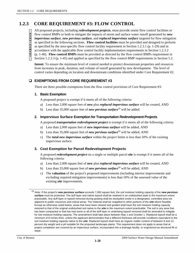
SECTION 1.2 CORE REQUIREMENTS
City of Renton 2009 Surface Water Design Manual Amendment
1-28
1.2.3 CORE REQUIREMENT #3: FLOW CONTROL All proposed projects, including redevelopment projects, must provide onsite flow control facilities or flow control BMPs or both to mitigate the impacts of storm and surface water runoff generated by new impervious surface, new pervious surface, and replaced impervious surface targeted for flow mitigation as specified in the following sections. Flow control facilities must be provided and designed to perform as specified by the area-specific flow control facility requirement in Section 1.2.3.1 (p. 1-29) and in accordance with the applicable flow control facility implementation requirements in Section 1.2.3.2 (p. 1-40). Flow control BMPs must be provided as directed by the flow control BMPs requirement in Section 1.2.3.3 (p. 1-45) and applied as specified by the flow control BMP requirements in Section 5.2.
Intent: To ensure the minimum level of control needed to protect downstream properties and resources from increases in peak, duration, and volume of runoff generated by new development. The level of control varies depending on location and downstream conditions identified under Core Requirement #2.
EXEMPTIONS FROM CORE REQUIREMENT #3 There are three possible exemptions from the flow control provisions of Core Requirement #3:
1. Basic Exemption A proposed project is exempt if it meets all of the following criteria: a) Less than 2,000 square feet of new plus replaced impervious surface will be created, AND b) Less than 35,000 square feet of new pervious surface19 will be added.
2. Impervious Surface Exemption for Transportation Redevelopment Projects A proposed transportation redevelopment project is exempt if it meets all of the following criteria: a) Less than 2,000 square feet of new impervious surface will be added, AND b) Less than 35,000 square feet of new pervious surface19 will be added, AND c) The total new impervious surface within the project limits is less than 50% of the existing
impervious surface.
3. Cost Exemption for Parcel Redevelopment Projects A proposed redevelopment project on a single or multiple parcel site is exempt if it meets all of the following criteria: a) Less than 2,000 square feet of new plus replaced impervious surface will be created, AND b) Less than 35,000 square feet of new pervious surface19 will be added, AND c) The valuation of the project's proposed improvements (including interior improvements and
excluding required mitigation improvements) is less than 50% of the assessed value of the existing site improvements.
19 Note: If the project's new pervious surface exceeds 7,000 square feet, the soil moisture holding capacity of the new pervious
surface must be protected. The duff layer and native topsoil shall be retained in an undisturbed state to the maximum extent practicable. Any duff layer or topsoil removed during grading shall be stockpiled onsite in a designated, controlled area not adjacent to public resources and critical areas. The material shall be reapplied to other portions of the site where feasible. Except as otherwise noted below, areas that have been cleared and graded shall have the soil moisture holding capacity restored to that of the original undisturbed soil native to the site to the maximum extent practicable. The soil in any area that has been compacted or that has had some or all of the duff layer or underlying topsoil removed shall be amended to mitigate for lost moisture-holding capacity. The amendment shall take place between May 1 and October 1. Replaced topsoil shall be a minimum of 8 inches thick, unless the applicant demonstrates that a different thickness will provide conditions equivalent to the soil moisture-holding capacity native to the site. Replaced topsoil shall have an organic matter content of between 8 and 13 percent dry weight and a pH suitable for the proposed landscape plants. This requirement does not apply to areas that at project completion are covered by an impervious surface, incorporated into a drainage facility, or engineered as structural fill or slope.
R E Q U I R E M E N T
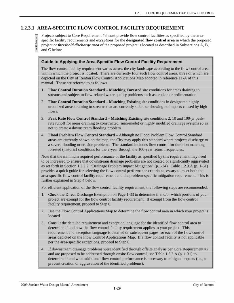
1.2.3 CORE REQUIREMENT #3: FLOW CONTROL
2009 Surface Water Design Manual Amendment City of Renton
1-29
1.2.3.1 AREA-SPECIFIC FLOW CONTROL FACILITY REQUIREMENT Projects subject to Core Requirement #3 must provide flow control facilities as specified by the area-specific facility requirements and exceptions for the designated flow control area in which the proposed project or threshold discharge area of the proposed project is located as described in Subsections A, B, and C below.
Guide to Applying the Area-Specific Flow Control Facility Requirement The flow control facility requirement varies across the city landscape according to the flow control area within which the project is located. There are currently four such flow control areas, three of which are depicted on the City of Renton Flow Control Applications Map adopted in reference 11-A of this manual. These are referred to as follows.
1. Flow Control Duration Standard – Matching Forested site conditions for areas draining to streams and subject to flow-related water quality problems such as erosion or sedimentation.
2. Flow Control Duration Standard – Matching Existing site conditions in designated highly urbanized areas draining to streams that are currently stable or showing no impacts caused by high flows.
3. Peak Rate Flow Control Standard – Matching Existing site conditions 2, 10 and 100-yr peak-rate runoff for areas draining to constructed (man-made) or highly modified drainage systems so as not to create a downstream flooding problem.
4. Flood Problem Flow Control Standard – Although no Flood Problem Flow Control Standard areas are currently shown on the map, the City may apply this standard where projects discharge to a severe flooding or erosion problems. The standard includes flow control for duration matching forested (historic) conditions for the 2-year through the 100-year return frequencies.
Note that the minimum required performance of the facility as specified by this requirement may need to be increased to ensure that downstream drainage problems are not created or significantly aggravated as set forth in Section 1.2.2.2, “Drainage Problem Impact Mitigation” (p.1-24). Table 1.2.3.A (p. 1-31) provides a quick guide for selecting the flow control performance criteria necessary to meet both the area-specific flow control facility requirement and the problem-specific mitigation requirement. This is further explained in Step 4 below.
For efficient application of the flow control facility requirement, the following steps are recommended.
1. Check the Direct Discharge Exemption on Page 1-33 to determine if and/or which portions of your project are exempt for the flow control facility requirement. If exempt from the flow control facility requirement, proceed to Step 6.
2. Use the Flow Control Applications Map to determine the flow control area in which your project is located.
3. Consult the detailed requirement and exception language for the identified flow control area to determine if and how the flow control facility requirement applies to your project. This requirement and exception language is detailed on subsequent pages for each of the flow control areas depicted on the Flow Control Applications Map. If a flow control facility is not applicable per the area-specific exceptions, proceed to Step 6.
4. If downstream drainage problems were identified through offsite analysis per Core Requirement #2 and are proposed to be addressed through onsite flow control, use Table 1.2.3.A (p. 1-31) to determine if and what additional flow control performance is necessary to mitigate impacts (i.e., to prevent creation or aggravation of the identified problems).
R E Q M T
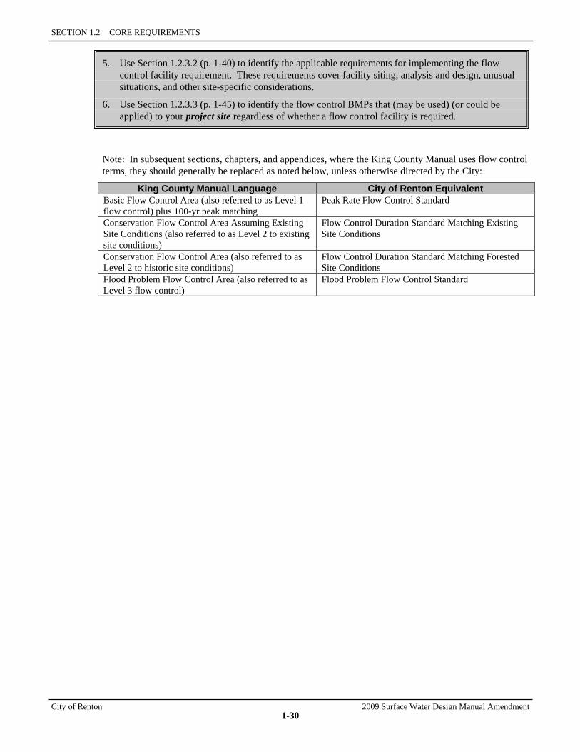
SECTION 1.2 CORE REQUIREMENTS
City of Renton 2009 Surface Water Design Manual Amendment
1-30
5. Use Section 1.2.3.2 (p. 1-40) to identify the applicable requirements for implementing the flow control facility requirement. These requirements cover facility siting, analysis and design, unusual situations, and other site-specific considerations.
6. Use Section 1.2.3.3 (p. 1-45) to identify the flow control BMPs that (may be used) (or could be applied) to your project site regardless of whether a flow control facility is required.
Note: In subsequent sections, chapters, and appendices, where the King County Manual uses flow control terms, they should generally be replaced as noted below, unless otherwise directed by the City:
King County Manual Language City of Renton Equivalent Basic Flow Control Area (also referred to as Level 1 flow control) plus 100-yr peak matching
Peak Rate Flow Control Standard
Conservation Flow Control Area Assuming Existing Site Conditions (also referred to as Level 2 to existing site conditions)
Flow Control Duration Standard Matching Existing Site Conditions
Conservation Flow Control Area (also referred to as Level 2 to historic site conditions)
Flow Control Duration Standard Matching Forested Site Conditions
Flood Problem Flow Control Area (also referred to as Level 3 flow control)
Flood Problem Flow Control Standard
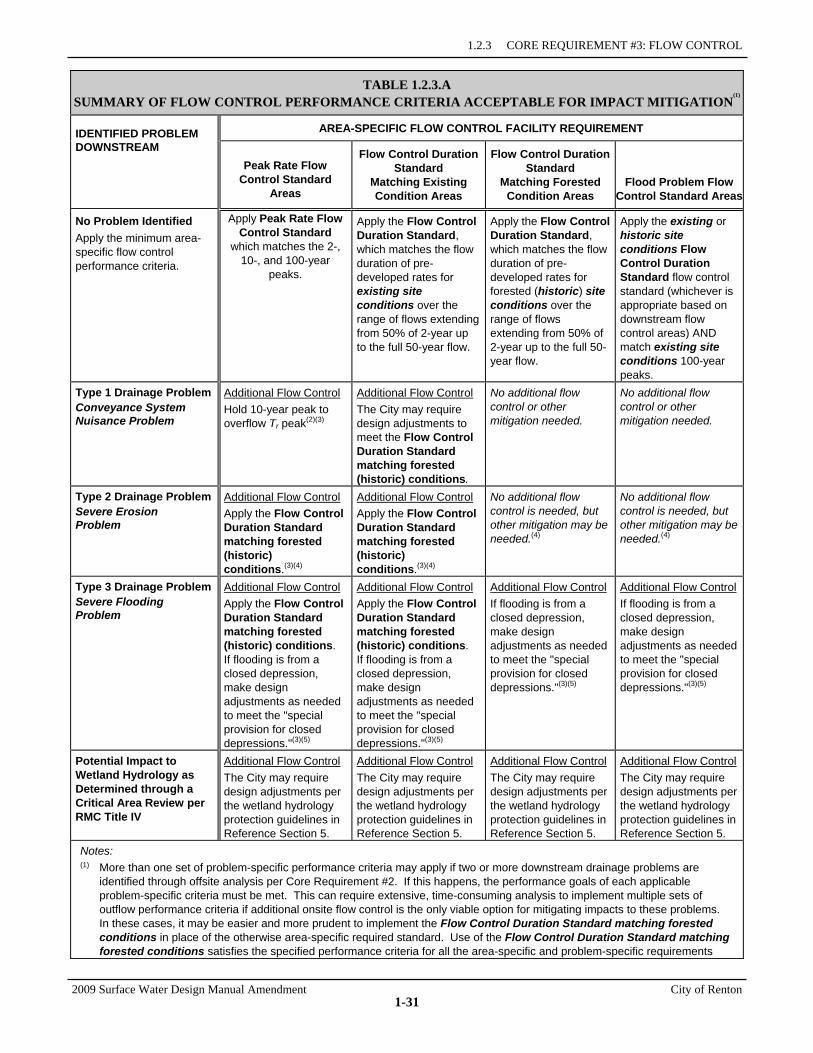
1.2.3 CORE REQUIREMENT #3: FLOW CONTROL
2009 Surface Water Design Manual Amendment City of Renton
1-31
TABLE 1.2.3.A SUMMARY OF FLOW CONTROL PERFORMANCE CRITERIA ACCEPTABLE FOR IMPACT MITIGATION
(1)
IDENTIFIED PROBLEM AREA-SPECIFIC FLOW CONTROL FACILITY REQUIREMENT DOWNSTREAM
Peak Rate Flow Control Standard
Areas
Flow Control Duration Standard
Matching Existing Condition Areas
Flow Control Duration Standard
Matching Forested Condition Areas
Flood Problem Flow Control Standard Areas
No Problem Identified Apply the minimum area-specific flow control performance criteria.
Apply Peak Rate Flow Control Standard
which matches the 2-, 10-, and 100-year
peaks.
Apply the Flow Control Duration Standard, which matches the flow duration of pre-developed rates for existing site conditions over the range of flows extending from 50% of 2-year up to the full 50-year flow.
Apply the Flow Control Duration Standard, which matches the flow duration of pre-developed rates for forested (historic) site conditions over the range of flows extending from 50% of 2-year up to the full 50-year flow.
Apply the existing or historic site conditions Flow Control Duration Standard flow control standard (whichever is appropriate based on downstream flow control areas) AND match existing site conditions 100-year peaks.
Type 1 Drainage Problem Conveyance System Nuisance Problem
Additional Flow Control Hold 10-year peak to overflow Tr peak(2)(3)
Additional Flow Control The City may require design adjustments to meet the Flow Control Duration Standard matching forested (historic) conditions.
No additional flow control or other mitigation needed.
No additional flow control or other mitigation needed.
Type 2 Drainage Problem Severe Erosion Problem
Additional Flow Control Apply the Flow Control Duration Standard matching forested (historic) conditions.(3)(4)
Additional Flow Control Apply the Flow Control Duration Standard matching forested (historic) conditions.(3)(4)
No additional flow control is needed, but other mitigation may be needed.(4)
No additional flow control is needed, but other mitigation may be needed.(4)
Type 3 Drainage Problem Severe Flooding Problem
Additional Flow Control Apply the Flow Control Duration Standard matching forested (historic) conditions. If flooding is from a closed depression, make design adjustments as needed to meet the "special provision for closed depressions."(3)(5)
Additional Flow Control Apply the Flow Control Duration Standard matching forested (historic) conditions. If flooding is from a closed depression, make design adjustments as needed to meet the "special provision for closed depressions."(3)(5)
Additional Flow Control If flooding is from a closed depression, make design adjustments as needed to meet the "special provision for closed depressions."(3)(5)
Additional Flow Control If flooding is from a closed depression, make design adjustments as needed to meet the "special provision for closed depressions."(3)(5)
Potential Impact to Wetland Hydrology as Determined through a Critical Area Review per RMC Title IV
Additional Flow Control The City may require design adjustments per the wetland hydrology protection guidelines in Reference Section 5.
Additional Flow Control The City may require design adjustments per the wetland hydrology protection guidelines in Reference Section 5.
Additional Flow Control The City may require design adjustments per the wetland hydrology protection guidelines in Reference Section 5.
Additional Flow Control The City may require design adjustments per the wetland hydrology protection guidelines in Reference Section 5.
Notes: (1) More than one set of problem-specific performance criteria may apply if two or more downstream drainage problems are
identified through offsite analysis per Core Requirement #2. If this happens, the performance goals of each applicable problem-specific criteria must be met. This can require extensive, time-consuming analysis to implement multiple sets of outflow performance criteria if additional onsite flow control is the only viable option for mitigating impacts to these problems. In these cases, it may be easier and more prudent to implement the Flow Control Duration Standard matching forested conditions in place of the otherwise area-specific required standard. Use of the Flow Control Duration Standard matching forested conditions satisfies the specified performance criteria for all the area-specific and problem-specific requirements
SECTION 1.2 CORE REQUIREMENTS
City of Renton 2009 Surface Water Design Manual Amendment
1-32
except if adjustments are required per the special provision for closed depressions described below in Note 5. (2) Overflow Tr is the return period of conveyance system overflow. To determine Tr requires a minimum Level 2 downstream
analysis as detailed in Section 2.3.1.1. To avoid this analysis, a Tr of 2 years may be assumed. (3) Offsite improvements may be implemented in lieu of or in combination with additional flow control as allowed in Section 1.2.2.2
(p. 1-24) and detailed in Section 3.3.5. (4) A tightline system may be required regardless of the flow control standard being applied if needed to meet the discharge
requirements of Core Requirement #1 (p. 1-19) or the outfall requirements of Core Requirement #4 (p. 1-49), or if deemed necessary by the City of Renton where the risk of severe damage is high.
(5) Special Provision for Closed Depressions with a Severe Flooding Problem: IF the proposed project discharges by overland flow or conveyance system to a closed depression experiencing a severe
flooding problem AND the amount of new impervious surface area proposed by the project is greater than or equal to 10% of the 100-year water surface area of the closed depression, THEN use the "point of compliance analysis technique" described in Section 3.3.6 to verify that water surface levels are not increasing for the return frequencies at which flooding occurs, up to and including the 100-year frequency. If necessary, iteratively adjust onsite flow control performance to prevent increases. Note: The point of compliance analysis relies on certain field measurements taken directly at the closed depression (e.g., soils tests, topography, etc.). If permission to enter private property for such measurements is denied, the City of Renton may waive this provision and apply the Flow Control Duration Standard matching forested conditions standard with a mandatory 20% safety factor on the storage volume.
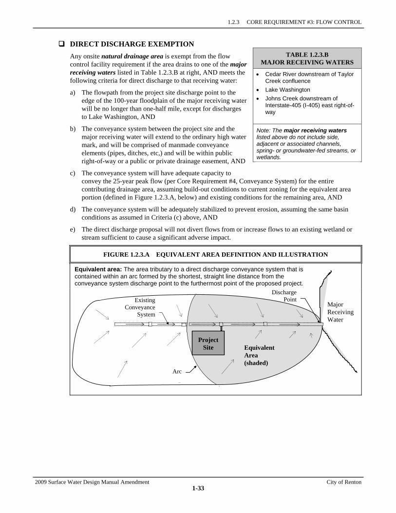
1.2.3 CORE REQUIREMENT #3: FLOW CONTROL
2009 Surface Water Design Manual Amendment City of Renton
1-33
DIRECT DISCHARGE EXEMPTION Any onsite natural drainage area is exempt from the flow control facility requirement if the area drains to one of the major receiving waters listed in Table 1.2.3.B at right, AND meets the following criteria for direct discharge to that receiving water:
a) The flowpath from the project site discharge point to the edge of the 100-year floodplain of the major receiving water will be no longer than one-half mile, except for discharges to Lake Washington, AND
b) The conveyance system between the project site and the major receiving water will extend to the ordinary high water mark, and will be comprised of manmade conveyance elements (pipes, ditches, etc,) and will be within public right-of-way or a public or private drainage easement, AND
c) The conveyance system will have adequate capacity to convey the 25-year peak flow (per Core Requirement #4, Conveyance System) for the entire contributing drainage area, assuming build-out conditions to current zoning for the equivalent area portion (defined in Figure 1.2.3.A, below) and existing conditions for the remaining area, AND
d) The conveyance system will be adequately stabilized to prevent erosion, assuming the same basin conditions as assumed in Criteria (c) above, AND
e) The direct discharge proposal will not divert flows from or increase flows to an existing wetland or stream sufficient to cause a significant adverse impact.
FIGURE 1.2.3.A EQUIVALENT AREA DEFINITION AND ILLUSTRATION
Equivalent area: The area tributary to a direct discharge conveyance system that is contained within an arc formed by the shortest, straight line distance from the conveyance system discharge point to the furthermost point of the proposed project.
TABLE 1.2.3.B MAJOR RECEIVING WATERS
• Cedar River downstream of Taylor Creek confluence
• Lake Washington • Johns Creek downstream of
Interstate-405 (I-405) east right-of-way
Note: The major receiving waters listed above do not include side, adjacent or associated channels, spring- or groundwater-fed streams, or wetlands.
Major Receiving Water
Arc
Project Site
DischargePoint
Equivalent Area (shaded)
Existing Conveyance
System
SECTION 1.2 CORE REQUIREMENTS
City of Renton 2009 Surface Water Design Manual Amendment
1-34
A. PEAK RATE FLOW CONTROL STANDARD AREAS The peak rate flow control standard is a peak-rate matching standard intended to prevent increases of peak flows for specific events rather than match flow-durations over a range of flows. The standard is appropriate for use in areas where the concern is flooding rather than stream bed erosion. Within the City of Renton, this standard is allowed for those areas that are highly urbanized prior to 1985 and that drain to pipes or non-fish bearing constructed conveyance systems leading to the lower Cedar River, Lake Washington or the portion of the Green River Valley floor located in Renton.
Minimum Required Performance Facilities in Peak Rate Flow Control Standard Areas must comply with the following flow control performance standards and assumptions unless modified by offsite analysis per Core Requirement #2 (see Table 1.2.3.A, p. 1-31):
Peak Rate Flow Control Standard: Match the developed peak discharge rates to existing site conditions peak discharge rates for 2-, 10-, and 100-year return periods.
Target Surfaces Facilities in Peak Rate Flow Control Standard Areas must mitigate (either directly or in effect) the runoff from the following target surfaces within the threshold discharge area for which the facility is required:
1. New impervious surface that is not fully dispersed per the criteria in Section 1.2.3.2 (p. 1-41). For individual lots within residential subdivision projects, the extent of new impervious surface shall be assumed as specified in Chapter 3. Note, any new impervious surface such as a bridge that spans the ordinary high water of a stream, pond, or lake may be excluded as a target surface if the runoff from such span is conveyed to the ordinary high water area in accordance with Criteria (b), (c), (d), and (e) of the "Direct Discharge Exemption" (p 1-33)
2. New pervious surface that is not fully dispersed. For individual lots within residential subdivision projects, the extent of new pervious surface shall be assumed to be the entire lot area, except the assumed impervious portion and any portion in which native conditions are preserved by covenant, tract, or easement. In addition, the new pervious surface on individual lots shall be assumed to be 100% grass.
Exceptions The following exceptions apply only in Peak Rate Flow Control Standard Areas:
1. The facility requirement in Peak Rate Flow Control Standard Areas is waived for any threshold discharge area in which the target surfaces subject to this requirement will generate no more than a 0.1-cfs increase in the existing site conditions 100-year peak flow. Note: for the purposes of this calculation, target surfaces served by flow control BMPs per Appendix C may be modeled in accordance with the flow control BMP facility sizing credits in Table 1.2.3.C (p. 1-42).
2. The facility requirement in Peak Rate Runoff Control Standard Areas may be waived for any threshold discharge area of a redevelopment project in which all of the following criteria are met:
a) The target surfaces subject to the Peak Rate Flow Control Standard Areas facility requirement will generate no more than a 0.1-cfs increase in the existing site conditions 100-year peak flow at any natural discharge location from the project site (note: for the purposes of this calculation, target surfaces served by flow control BMPs per Appendix C may be modeled in accordance with the flow control BMP facility sizing credits in Table 1.2.3.C, p. 1-42), AND
b) The increased runoff from target surfaces will not significantly impact a critical area, severe flooding problem, or severe erosion problem.
1.2.3 CORE REQUIREMENT #3: FLOW CONTROL
2009 Surface Water Design Manual Amendment City of Renton
1-35
B. FLOW CONTROL DURATION STANDARD AREAS The flow control duration standard requires runoff from urban developments to be detained and released at a rate that matches the flow duration of predeveloped rates over the range of flows extending from ½ of the 2-year up to the 50-year flow. Also match developed peak discharge rates to predeveloped peak discharge rates for the 2- and 10-year return periods. Flow duration specifies the cumulative amount of time that various flows are equaled or exceeded during a long-term simulation using historical rainfall. The target flow duration may be the “historic” (i.e., fully forested condition) or in specific situations it may be the existing site or “pre-project” condition as described below. The Flow Control Applications Map shows the areas where the “forested” and “existing” conditions are allowed.
Forested land cover – Runoff from the developed site will be controlled and released at a rate that matches the flow duration for a forested (“historic”) land cover. The “historic” land cover is the default standard required by the technical requirements of the NPDES permit. The standard is applicable to those areas draining to streams that have erodible channels where runoff from urban areas has the potential to destabilize the channel.
Existing land cover – Runoff from the developed site will be controlled and released at a rate that matches the flow duration for the site conditions existing before the development. These are areas that have been developed for years and drain to stream channels that have become stabilized to a new hydrologic regime. Ecology has proposed that the existing land cover can be used in basins that have had at least 40% total impervious surface area for the 20 years preceding Ecology’s adoption of the 2005 Stormwater Management Manual for Western Washington (called the 40/20 rule) and the stream channels receiving the runoff are considered stable from the standpoint of excessive erosion or sedimentation. In developing the “40/20 rule” for highly urbanized basins, Ecology conducted a preliminary analysis and produced maps that identify those areas that may meet the criteria. Portions of Renton were included in the initial maps prepared by Ecology. These maps have been adjusted to better represent the areas that were 40% impervious in 1985 as well as drainage basin divides within the City.
Flow control facilities designed to the “40/20 rule” will only have to mitigate for the added impervious surface. As a result, these flow control facilities will be smaller than those required to be designed to match runoff from a fully forested site.
Minimum Required Performance Facilities in Flow Control Duration Standard Areas must comply with the following flow control performance standard and assumptions unless modified by offsite analysis per Core Requirement #2 (see Table 1.2.3.A, p. 1-31):
Flow Control Duration Standard Matching Forested Site Conditions: Match developed discharge durations to predeveloped durations for the range of predeveloped discharge rates from 50% of the 2-year peak flow up to the full 50-year peak flow. Also match developed peak discharge rates to predeveloped peak discharge rates for the 2- and 10-year return periods. Assume forested (historic) site conditions as the predeveloped condition.
Flow Control Duration Standard Matching Existing Site Conditions: Match developed discharge durations to predeveloped durations for the range of predeveloped discharge rates from 50% of the 2-year peak flow up to the full 50-year peak flow. Also match developed peak discharge rates to predeveloped peak discharge rates for the 2- and 10-year return periods. Assume existing site conditions as the predeveloped condition. Effectiveness in Addressing Downstream Drainage Problems While the Flow Control Duration Standard flow control standard assuming historic site conditions provides a reasonable level of protection for preventing most development-induced problems, it does not necessarily prevent increases in existing site conditions 100-year peak flows that can aggravate severe flooding problems as described in Core Requirement #2, nor does it necessarily prevent aggravation of all severe erosion problems. Consequently, if one or more of these problems are identified through offsite analysis per Core Requirement #2, additional onsite flow control and/or
SECTION 1.2 CORE REQUIREMENTS
City of Renton 2009 Surface Water Design Manual Amendment
1-36
offsite improvements will likely be required (see "Drainage Problem-Specific Mitigation Requirements" in Section 1.2.2.2, p. 1-26).
Target Surfaces Facilities in Flow Control Duration Standard Areas20 must mitigate (either directly or in effect) the runoff from the following target developed surfaces within the threshold discharge area for which the facility is required:
1. New impervious surface that is not fully dispersed per the criteria on Page 1-41. For individual lots within residential subdivision projects, the extent of new impervious surface shall be assumed as specified in Chapter 3. Note, any new impervious surface such as a bridge that spans the ordinary high water of a stream, pond, or lake may be excluded as a target surface if the runoff from such span is conveyed to the ordinary high water area in accordance with Criteria (b), (c), (d), and (e) of the "Direct Discharge Exemption," p 1-33).
2. New pervious surface that is not fully dispersed. For individual lots within residential subdivision projects, the extent of new pervious surface shall be assumed to be the entire lot area, except the assumed impervious portion and any portion in which native conditions are preserved by covenant, tract, or easement. In addition, the new pervious surface on individual lots shall be assumed to be 100% grass.
3. Replaced impervious surface that is not fully dispersed on a transportation redevelopment project in which new impervious surface is 5,000 square feet or more and totals 50% or more of the existing impervious surface within the project limits.
4. Replaced impervious surface that is not fully dispersed on a parcel redevelopment project in which the total of new plus replaced impervious surface is 5,000 square feet or more and whose valuation of proposed improvements (including interior improvements and excluding required mitigation improvements) exceeds 50% of the assessed value of the existing site improvements.
Exceptions The following exceptions apply only in Flow Control Duration Standard Areas:
1. The facility requirement in Flow Control Duration Standard Matching Existing Site Conditions Areas is waived for any threshold discharge area in which there is no more than a 0.1-cfs difference in the sum of developed 100-year peak flows for those target surfaces subject to this requirement and the sum of existing site conditions 100-year peak flows for the same surface areas. Note: for the purposes of this calculation, target surfaces served by flow control BMPs per Appendix C may be modeled in accordance with the flow control BMP facility sizing credits in Table 1.2.3.C (p. 1-42).
2. The facility requirement in Flow Control Duration Standard Matching Forested Site Conditions Areas is waived for any threshold discharge area in which there is no more than a 0.1-cfs difference in the sum of developed 100-year peak flows for those target surfaces subject to this requirement and the sum of forested (historic) site conditions 100-year peak flows for the same surface areas. Note: for the purposes of this calculation, target surfaces served by flow control BMPs per Appendix C may be modeled in accordance with the flow control BMP facility sizing credits in Table 1.2.3.C (p. 1-42).
3. The facility requirement in Flow Control Duration Standard Areas may be reduced or waived for any threshold discharge area where a basin plan or basin study approved by the City and Ecology shows that a lower standard (e.g., Peak Rate Control Standard or targeting existing site conditions
20 Note: Any threshold discharge area that appears to be located within a Duration Control Standard Area according to the Flow
Control Applications Map but drains entirely by non-erodible manmade conveyance to a major receiving water (listed on page 1-33) is considered to be located within a Peak Rate Standard Control Area.
1.2.3 CORE REQUIREMENT #3: FLOW CONTROL
2009 Surface Water Design Manual Amendment City of Renton
1-37
instead of forested conditions) is sufficient or no facility is necessary to protect or allow for restoration of water body beneficial uses and habitat functions essential to salmonids.
4. The facility requirement in Flow Control Duration Standard Areas as applied to replaced impervious surface may be reduced by the RDSD Manager/designee using the adjustment process detailed in Section 1.4, if the cost of flow control facilities to mitigate all target surfaces exceeds that necessary to mitigate only for new impervious surface plus new pervious surface and also exceeds 1/3 of the valuation of proposed improvements (including interior improvements) or twice the cost of a facility to mitigate equivalent surfaces on a new development site, whichever is less. The amount of reduction shall be limited such that the cost of flow control facilities is at least equal to that necessary to mitigate only for new impervious surface plus new pervious surface, and beyond this amount, is no greater than 1/3 of the valuation of proposed improvements (including interior improvements) or twice the cost of a facility to mitigate equivalent surfaces on a new development site, whichever is less.
C. FLOOD PROBLEM FLOW CONTROL STANDARD AREAS Flood Problem Flow Control Standard Areas are designated by the City of Renton where the City has determined that a higher average level of flow control is needed to prevent aggravation of existing documented flooding problems. At this time, the City has not mapped specific areas, but may apply this standard when a project discharges to a severe flooding or erosion problem.
Within Flood Problem Flow Control Standard Areas, or where required by the City to protect aggravation of a downstream problem, required flow control facilities must comply with the following minimum requirements for facility performance and mitigation of targeted surfaces, except where such requirements or the facility requirement itself is waived or reduced by the area-specific exceptions at the end of this subsection.
Minimum Required Performance Facilities in Flood Problem Flow Control Standard Areas must comply with the following flow control performance standard and assumptions unless modified by offsite analysis per Core Requirement #2 (see Table 1.2.3.A, p. 1-31):
Flood Problem Flow Control: Apply the Flow Control Duration Standard flow control standard, AND match the developed 100-year peak discharge rate to the predeveloped 100-year peak discharge rate. If the Flood Problem Flow Control Area is located within a Duration Control Standard Area and does not drain entirely by non-erodible manmade conveyance to a major receiving water (listed on page 1-33), then historic site conditions shall be assumed as the predeveloped condition except for the purposes of matching 100-year peak discharge rates. For all other situations and for the purposes of matching 100-year peak discharge rates, existing site conditions may be assumed.
Intent The Flood Problem Flow Control flow control standard is intended to prevent significant increases in existing water surface levels for 2-year through 100-year return frequencies. Such increases are expected to occur as the volume of runoff discharging to the water body is increased by upstream development. Because inflow rates to these water bodies are typically much higher than the outflow rates, increased runoff volumes from upstream development are, in effect, stacked on top of existing volumes in the water body, resulting in higher water surface levels. The duration-matching and 100-year peak-matching criteria of the Flood Problem Flow Control flow control standard counteract this stacking effect by slowing the arrival of additional runoff volumes. Because it can prevent significant aggravation of existing flooding, the Flood Problem Flow Control standard is also applicable to other flow control areas where severe flooding problems have been identified per Core Requirement #2.
R E Q MT
SECTION 1.2 CORE REQUIREMENTS
City of Renton 2009 Surface Water Design Manual Amendment
1-38
Effectiveness in Addressing Downstream Drainage Problems If the Flood Problem Flow Control flow control standard is implemented onsite, no additional measures are required to prevent aggravation of the three types of downstream drainage problems described in Core Requirement #2. The one exception is for a wetland or lake that is a closed depression with a severe flooding problem, and the proposed project is adding impervious surface area amounting to more than 10% of the 100-year water surface area of the closed depression. In this case, additional onsite flow control or offsite improvements may be necessary as determined by a "point of compliance analysis" (see "Special Provision for Closed Depressions" in Table 1.2.3.A, p. 1-31), and see Section 3.3.6, "Point of Compliance Analysis,").
Target Surfaces Facilities in Flood Problem Flow Control Standard Areas must mitigate (either directly or in effect) the runoff from the following target developed surfaces within the threshold discharge area for which the facility is required:
1. If the Flood Problem Flow Control Area is located within a Flow Control Duration Standard Area, then the target surfaces are the same as those required for facilities in Flow Control Duration Standard Area unless otherwise allowed by the area-specific exceptions. Note: Any Flood Problem Flow Control Area that appears to be located within a Flow Control Duration Standard Area identified on the Flow Control Applications Map, but drains entirely by non-erodible manmade conveyance to a major receiving water (listed on page 1-33), is considered to be located within a Basic Flow Control Area.
2. If the Flood Problem Flow Control Standard Area is located within a Peak Rate Flow Control Area or drains entirely by non-erodible manmade conveyance to a major receiving water, then the target surfaces are the same as those required for facilities in Peak Rate Flow Control Areas (see p. 1-34).
Exceptions The following exceptions apply only in Flood Problem Flow Control Standard Areas:
1. If the Flood Problem Flow Control Area is located within a Flow Control Duration Standard Matching Existing Site Conditions Area or Peak Rate Flow Control Area, then the facility requirement is waived for any threshold discharge area in which there is no more than a 0.1-cfs difference in the sum of developed 100-year peak flows for the target surfaces subject to this requirement and the sum of existing site conditions 100-year peak flows for the same surface areas. Note: for the purposes of this calculation, target surfaces served by flow control BMPs per Appendix C may be modeled in accordance with the flow control BMP facility sizing credits in Table 1.2.3.C (p. 1-42). Also, any Flood Problem Flow Control Area that appears to be located within a Duration Control Standard Area identified on the Flow Control Applications Map, but drains entirely by non-erodible manmade conveyance to a major receiving water (listed on page 1-33), is considered to be located within a Peak Rate Flow Control Area.
2. If the Flood Problem Flow Control Area is located within a Flow Control Duration Standard Matching Forested Site Conditions Area, then the facility requirement is waived for any threshold discharge area in which there is no more than a 0.1-cfs difference in the sum of developed 100-year peak flows for the target surfaces subject to this requirement and the sum of forested (historic) site conditions 100-year peak flows for the same surface areas. Note: for the purposes of this calculation, target surfaces served by flow control BMPs per Appendix C may be modeled in accordance with the flow control BMP facility sizing credits in Table 1.2.3.C (p. 1-42). Also, any Flood Problem Flow Control Area that appears to be located within a Duration Control Standard Area identified on the Flow Control Applications Map, but drains entirely by non-erodible manmade conveyance to a major receiving water (listed on page 1-33), is considered to be located within a Peak Rate Runoff Control Area.

1.2.3 CORE REQUIREMENT #3: FLOW CONTROL
2009 Surface Water Design Manual Amendment City of Renton
1-39
3. Any required application of the Flood Problem Flow Control Areas facility requirement to replaced impervious surface may be waived if the City has adopted a basin plan and implementation schedule approved by the state Department of Ecology for fulfilling this requirement with regional facilities.
4. Any required application of the Flood Problem Flow Control Areas facility requirement to replaced impervious surface may be reduced by the RDSD Manager/designee using the adjustment process detailed in Section 1.4, if the cost of flow control facilities to mitigate all target surfaces exceeds that necessary to mitigate only for new impervious surface plus new pervious surface and also exceeds 1/3 of the valuation of proposed improvements (including interior improvements) or twice the cost of a facility to mitigate equivalent surfaces on a new development site, whichever is less. The amount of reduction shall be limited such that the cost of flow control facilities is at least equal to that necessary to mitigate only for new impervious surface plus new pervious surface, and beyond this amount, is no greater than 1/3 of the valuation of proposed improvements (including interior improvements) or twice the cost of a facility to mitigate equivalent surfaces on a new development site, whichever is less.
5. Any required application of the Flood Problem Flow Control Areas facility requirement to replaced impervious surface may assume existing site conditions as the predeveloped condition for the purposes of matching the developed 100-year peak discharge rate to the predeveloped 100-year peak discharge rate.
SECTION 1.2 CORE REQUIREMENTS
City of Renton 2009 Surface Water Design Manual Amendment
1-40
1.2.3.2 FLOW CONTROL FACILITY IMPLEMENTATION REQUIREMENTS Flow control facilities shall be designed and implemented in accordance with the following requirements, allowances, and flexible compliance provisions:
A. ONSITE VS. OFFSITE IMPLEMENTATION All required flow control facilities must be implemented onsite except where the requirements below can be met by direct discharge to a regional or shared facility constructed to provide flow control for the proposed project. Regional facilities are typically constructed as part of a City-approved plan or study (e.g., basin plan, stormwater compliance plan, or master drainage plan). Shared facilities may be constructed under a City-developed shared facility drainage plan or under an agreement between two or more private developers.
1. The regional or shared facility must be of adequate size and design to meet the current flow control requirements for the proposed project. Note: the current flow control requirements are those specified by Core Requirement #3 of this manual unless superseded by other adopted area-specific flow control requirements per Special Requirement #1 (see Section 1.3.1). In some cases where the current flow control requirements differ from those used to originally design the regional or shared facility, additional analysis and possible retrofitting of the facility may be required to ensure adequate size and design.
2. The regional or shared facility must be fully operational at the time of construction of the proposed project. In the case of a shared facility, the proposed project must comply with the terms and conditions of all contracts, agreements, and permits associated with the shared facility. If the offsite facility is an existing City of Renton-owned facility, the City may charge a special use fee equal to or based on the property value of the detention capacity being used.
3. The conveyance system between the project site and the regional facility must meet the same criteria specified for direct discharge to a major receiving water except for Criterion (a) (see "Direct Discharge Exemption" on page 1-33). In the case of a shared facility, the criteria are the same, except the conveyance system need only have adequate capacity and erosion protection for buildout of the participating portion21 of the contributing drainage area.
B. METHODS OF ANALYSIS AND DESIGN Flow control facilities must be analyzed and designed using a continuous flow simulation method such as HSPF (Hydrologic Simulation Program FORTRAN) or the simplified HSPF-based runoff files method. Specifications for use of the runoff files method and associated computer program, KCRTS, are found in Chapter 3. Detailed design specifications for flow control facilities are found in Chapter 5.
C. SIZING CREDITS FOR FULLY DISPERSED SURFACES A fully dispersed surface (either impervious or non-native pervious) is one that conforms to the BMP strategy for "full dispersion" detailed in Appendix C, Section C.2.1. This strategy calls for minimizing the area of onsite developed surface relative to native vegetated surface, together with the application of dispersion techniques that utilize the natural retention/detention capacity of the native vegetated surface to mitigate the runoff effects of the developed surfaces. Developed surfaces conforming to this strategy are considered to have a negligible impact downstream, and therefore, may be modeled as forest and are not subject to the area-specific flow control facility requirement (Section 1.2.3.1) or the land-use-specific water quality facility requirement (Section 1.2.8.1). In order for developed surfaces to qualify as fully dispersed, they must meet the basic criteria listed below and further detailed in Appendix C, Section C.2.1.
21 The participating portion includes those properties that have agreements for use of the shared facility.
1.2.3 CORE REQUIREMENT #3: FLOW CONTROL
2009 Surface Water Design Manual Amendment City of Renton
1-41
Criteria for Fully Dispersed Surfaces 1. The total area of impervious surface being fully dispersed must be no more than 15% of the total
area of native vegetated surface being preserved by a clearing limit by a City-approved recorded tract, easement, or covenant within the same threshold discharge area. The total area of impervious surface plus non-native pervious surface22 being fully dispersed must be no more than 35% of a threshold discharge area.
2. The runoff from a fully dispersed surface must be discharged using one of the following dispersion devices in accordance with the design specifications and maximum area of fully dispersed surface for each device set forth in Appendix C, Section C.2.1:
a) Splash blocks
b) Rock pads
c) Gravel filled trenches
d) Sheet flow
Note: The dispersion device must be situated so as to discharge within the same threshold discharge area of the surface it serves.
3. A native vegetated flowpath segment of at least 100 feet in length (25 feet for sheet flow from a non-native pervious surface) must be available along the flowpath that runoff would follow upon discharge from a dispersion device listed in Minimum Requirement 2 above. The native vegetated flowpath segment must meet all of the following criteria:
a) The flowpath segment must be over native vegetated surface.
b) The flowpath segment must be onsite or an offsite tract or easement area reserved for such dispersion.
c) The slope of the flowpath segment must be no steeper than 15% for any 20-foot reach of the flowpath segment.
d) The flowpath segment must be located between the dispersion device and any downstream drainage feature such as a pipe, ditch, stream, river, pond, lake, or wetland.
e) The flowpath segments for adjacent dispersion devices must comply with the minimum spacing requirements in Appendix C, Section C.2.1. These requirements do not allow overlap of flowpath segments, except in the case where sheet flow from a non-native pervious surface overlaps with the flowpath of any dispersion device listed in Minimum Requirement 2 above. In this case, the longest of the two overlapping flowpath segments must be extended at least 1 foot for every 3 feet of distance along the most representative path that runoff would travel from the upstream end to the discharge end of the non-native pervious surface.
4. On sites with septic systems, the discharge of runoff from dispersion devices must not be upgradient of the drainfield. This requirement may be waived by RDSD if site topography clearly prohibits flows from intersecting the drainfield.
5. The dispersion of runoff must not create flooding or erosion impacts as determined by RDSD. If runoff is proposed to be discharged toward a landslide hazard area, erosion hazard area, or steep slope hazard area (i.e., slopes steeper than 20%), RDSD may require the applicant to have the proposal evaluated by a geotechnical engineer or engineering geologist.
22 Non-native pervious surface means a pervious surface that does not meet the definition of a native vegetated surface.
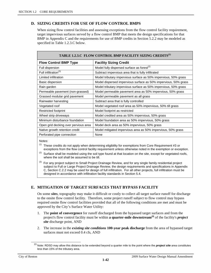
SECTION 1.2 CORE REQUIREMENTS
City of Renton 2009 Surface Water Design Manual Amendment
1-42
D. SIZING CREDITS FOR USE OF FLOW CONTROL BMPS When sizing flow control facilities and assessing exceptions from the flow control facility requirement, target impervious surfaces served by a flow control BMP that meets the design specifications for that BMP in Appendix C and the requirements for use of BMP credits in Section 5.2.2 may be modeled as specified in Table 1.2.3.C below.
TABLE 1.2.3.C FLOW CONTROL BMP FACILITY SIZING CREDITS(1)
Flow Control BMP Type Facility Sizing Credit Full dispersion Model fully dispersed surface as forest(2)
Full infiltration(3) Subtract impervious area that is fully infiltrated Limited infiltration Model tributary impervious surface as 50% impervious, 50% grass Basic dispersion Model dispersed impervious surface as 50% impervious, 50% grass Rain garden Model tributary impervious surface as 50% impervious, 50% grass Permeable pavement (non-grassed) Model permeable pavement area as 50% impervious, 50% grass Grassed modular grid pavement Model permeable pavement as all grass Rainwater harvesting Subtract area that is fully controlled Vegetated roof Model vegetated roof area as 50% impervious, 50% till grass Restricted footprint Model footprint as restricted Wheel strip driveways Model credited area as 50% impervious, 50% grass Minimum disturbance foundation Model foundation area as 50% impervious, 50% grass Open grid decking over pervious area Model deck area as 50% impervious, 50% grass Native growth retention credit Model mitigated impervious area as 50% impervious, 50% grass Perforated pipe connection None
Notes: (1) These credits do not apply when determining eligibility for exemptions from Core Requirement #3 or
exceptions from the flow control facility requirement unless otherwise noted in the exemption or exception. (2) Surface shall be modeled using the soil type found at that location on the site, except for vegetated roofs,
where the soil shall be assumed to be till. (3) For any project subject to Small Project Drainage Review, and for any single family residential project
subject to Full or Large Project Drainage Review, the design requirements and specifications in Appendix C, Section C.2.2 may be used for design of full infiltration. For all other projects, full infiltration must be designed in accordance with infiltration facility standards in Section 5.4.
E. MITIGATION OF TARGET SURFACES THAT BYPASS FACILITY On some sites, topography may make it difficult or costly to collect all target surface runoff for discharge to the onsite flow control facility. Therefore, some project runoff subject to flow control may bypass required onsite flow control facilities provided that all of the following conditions are met and must be approved by the City’s Surface Water Utility:
1. The point of convergence for runoff discharged from the bypassed target surfaces and from the project's flow control facility must be within a quarter-mile downstream23 of the facility's project site discharge point, AND
2. The increase in the existing site conditions 100-year peak discharge from the area of bypassed target surfaces must not exceed 0.4 cfs, AND
23 Note: RDSD may allow this distance to be extended beyond a quarter mile to the point where the project site area constitutes
less than 15% of the tributary area.
1.2.3 CORE REQUIREMENT #3: FLOW CONTROL
2009 Surface Water Design Manual Amendment City of Renton
1-43
3. Runoff from the bypassed target surfaces must not create a significant adverse impact to downstream drainage systems, salmonid habitat, or properties as determined by RDSD, AND
4. Water quality requirements applicable to the bypassed target surfaces must be met, AND
5. Compensatory mitigation by a flow control facility must be provided so that the net effect at the point of convergence downstream is the same with or without the bypass. This mitigation may be waived if the existing site conditions 100-year peak discharge from the area of bypassed target surfaces is increased by no more than 0.1 cfs and flow control BMPs as detailed in Appendix C are applied to all impervious surfaces within the area of bypassed target surfaces. One or combination of the following methods may be used to provide compensatory mitigation by a flow control facility subject to permission/approvals from other parties as deemed necessary by RDSD:
a) Design the project's flow control facility or retrofit an existing offsite flow control facility as needed to achieve the desired effect at the point of convergence, OR
b) Design the project's flow control facility or provide/retrofit an offsite flow control facility to mitigate an existing developed area (either onsite or offsite) that has runoff characteristics (i.e., peak flow and volume) equivalent to those of the bypassed target surfaces but is currently not mitigated or required to be mitigated to the same flow control performance requirement as the bypassed target surfaces. Consideration of an offsite area to be mitigated for must take into account the likelihood of that area redeveloping in the future. Those areas determined by the City to have a high likelihood of future redevelopment that will provide its own mitigation may not be used as compensatory mitigation.
F. BYPASS OF RUNOFF FROM NON-TARGET SURFACES The performance of flow control facilities can be compromised if the contributing area, beyond that which must be mitigated by the facility, is too large. Therefore, IF the existing 100-year peak flow rate from any onsite, upstream area (not targeted for mitigation) is greater than 50% of the 100-year developed peak flow rate (undetained) for the area that must be mitigated, THEN the runoff from the upstream area must bypass the facility. Offsite areas that naturally drain onto the project site must be intercepted at the natural drainage course within the project site and conveyed in a separate conveyance system and must bypass onsite stormwater facilities. The bypass of upstream runoff must be designed so that all of the following conditions are met:
1. Any existing contribution of flows to an onsite wetland must be maintained, AND
2. Upstream flows that are naturally attenuated by natural detention on the project site under predeveloped conditions must remain attenuated, either by natural means or by providing additional onsite detention so that peak flows do not increase, AND
3. Upstream flows that are dispersed or unconcentrated on the project site under predeveloped conditions must be discharged in a safe manner as described in Core Requirement #1 under "Discharge Requirements" (p. 1-19).
4. Bypasses shall be designed in accordance with standards of Core Requirement #4, Conveyance System
G. MITIGATION TRADES A project's flow control facility may be designed to mitigate an existing developed non-target surface area (either onsite or offsite) in trade for not mitigating part or all of the project's target surface area, provided that all of the following conditions are met: 1. The existing developed non-target surface area (i.e., an area of existing impervious surface and/or
non-native pervious surface) must have runoff discharge characteristics (i.e., peak flow and volume) equivalent to those of the target surface area for which mitigation is being traded and must not be currently mitigated to the same flow control performance requirement as the target surface area, AND
SECTION 1.2 CORE REQUIREMENTS
City of Renton 2009 Surface Water Design Manual Amendment
1-44
2. Runoff from both the target surface area being traded and the flow control facility must converge prior to discharge of the runoff from the target surface area being traded onto private property without an easement or through any area subject to erosion, AND
3. The net effect in terms of flow control at the point of convergence downstream must be the same with or without the mitigation trade, AND
4. The undetained runoff from the target surface area being traded must not create a significant adverse impact to downstream drainage systems, salmonid habitat, or properties prior to convergence with runoff from the flow control facility.
5. Consideration of an offsite area to be mitigated for must take into account the likelihood of that area redeveloping in the future. Those areas determined by the City to have a high likelihood of future redevelopment that will provide its own mitigation may not be used as a mitigation trade.
6. Mitigation trade proposals must be reviewed and approved with input from the City’s Surface Water Utility.
H. MANIFOLD DETENTION FACILITIES A manifold detention facility is a single detention facility designed to take the place of two or more otherwise required detention facilities. It combines the runoff from two or more onsite drainage areas having separate natural discharge locations, and redistributes the runoff back to the natural discharge locations following detention. Because manifold detention facilities divert flows from one natural discharge location to another and then back, they are not allowed except by an approved adjustment (see Section 1.4).
I. FACILITY REQUIREMENT IN LANDSLIDE HAZARD DRAINAGE AREAS Proposed projects subject to Discharge Requirement 2 in Core Requirement #1 (see p. 1-20) must provide a tightline system unless the 100-year runoff from the project site can be feasibly infiltrated or one of the other exceptions listed on page 1-20 apply. For infiltration to be used as an alternative to the tightline requirement, it must be feasible per the facility design requirements and limitations specified in Section 5.4. When evaluating the feasibility of infiltration, multiple facility locations scattered throughout the project site shall be considered and used where feasible and practical to avoid concentrating infiltrated water in one location. If multiple facilities are not feasible or practical, then a single infiltration facility meeting the minimum setback requirements in Section 5.4 may be used where feasible.
Where infiltration is not feasible, it is still possible for a proposed project to qualify for one of the other exceptions to the tightline requirement specified in Core Requirement #1 (p. 1-20). If such a project is subject to the flow control facility requirement in Core Requirement #3, the required facility must be a detention pond sized to meet, at minimum, the Flow Control Duration Standard Matching Forested site conditions flow control facility standard with a safety factor of 20% applied to the storage volume. The detention pond must be sited and designed so as to maximize the opportunity for infiltration in the pond. To accomplish this, all of the following design requirements must be met: 1. The detention pond must be preceded by either a water quality treatment facility per Core
Requirement #8 or a presettling basin per Section 5.4, AND 2. All detention pond side slopes must be 3H:1V or flatter and must be earthen, AND 3. Detention pond liners that impede infiltration shall not be used, AND 4. The pond bottom shall be at or above the seasonal high groundwater table, AND 5. The detention pond outflow must meet the discharge dispersal requirements specified in Discharge
Requirement 1 of Core Requirement #1 (p. 1-19).
1.2.3 CORE REQUIREMENT #3: FLOW CONTROL
2009 Surface Water Design Manual Amendment City of Renton
1-45
1.2.3.3 FLOW CONTROL BMPS REQUIREMENT Projects subject to Core Requirement #3 must apply flow control BMPs to impervious surfaces as directed by this section to either supplement the flow mitigation provided by required flow control facilities or provide flow mitigation where flow control facilities are not required. Flow control BMPs must be selected and applied according to the basic requirements, procedures, and provisions detailed in Section 5.2 and the design specifications for each BMP in Appendix C, Section C.2.
Flow control BMPs are methods and designs for dispersing, infiltrating, or otherwise reducing or preventing development-related increases in runoff at or near the sources of those increases. Flow control BMPs include, but are not limited to, preservation and use of native vegetated surfaces to fully disperse runoff; use of other pervious surfaces to disperse runoff; roof downspout infiltration; permeable pavements; rainwater harvesting; vegetated roofs; and reduction of development footprint.
Intent: To provide mitigation of hydrologic impacts that are not possible/practical to mitigate with a flow control facility. Such impacts include increases in runoff volumes and flashiness and decreases in groundwater recharge. Increased runoff volume and flashiness leads to higher and more variable stream velocities at low flows and more frequent water level fluctuations in streams and wetlands. This causes wash-out and stranding of aquatic species, algal scour and washout of organic matter, loss of vegetation diversity and habitat quality, and disruption of cues for spawning, egg hatching, and migration. Decreased groundwater recharge reduces water supply for human use and summer base flows in streams, which is critical to water temperature, salmonid use of smaller streams, and the habitat quality of mainstem side channels and wetlands used for spawning, rearing, and flood refuge. Flow control BMPs seek to reduce runoff volumes and flashiness and increase groundwater recharge by reducing imperviousness and making use of the pervious portions of development sites to maximize infiltration and retention of stormwater onsite. Thus, the goal is to apply flow control BMPs to new and replaced impervious surfaces to the maximum extent practicable without causing flooding or erosion impacts. The minimum levels of application specified in Section 5.2 are considered by the City to be a maximum extent practicable level based on best available information regarding the effectiveness of these BMPs versus their cost.
INFILTRATION FACILITY EXEMPTION Any impervious surface served by an infiltration facility designed in accordance with the flow control facility requirement (Section 1.2.3.1), the facility implementation requirements (Section 1.2.3.2), and the design criteria for infiltration facilities (Section 5.4) is exempt from the flow control BMPs requirement.
IMPLEMENTATION OF THIS REQUIREMENT For non-subdivision projects making improvements on an individual site/lot, implementation of this requirement shall be in accordance with the "Individual Lot BMP Requirements" in Section 5.2.1, which specify the selection of BMPs and the extent of their application to the impervious surfaces of the site/lot. This required implementation of flow control BMPs must occur as part of the proposed project and provisions must be made for their future maintenance as specified in Section 5.2.1.
For subdivision projects or projects within rights-of-way (e.g., road improvements), implementation of this requirement is incentive-based. In other words, implementation is achieved by giving credits for the application of flow control BMPs per Table 1.2.3.C (p. 1-42). As allowed in Sections 1.2.3 and 1.2.8, these credits may be used to reduce the size of a required flow control facility, qualify for a flow control facility exception or bypass of target surfaces, or reduce the target surfaces subject to flow control or water quality facility requirements. To use these credits, flow control BMPs must be implemented as part of the proposed project and provisions must be made for their future maintenance as specified in Section 5.2.2. For subdivision projects proposing to take credit for future implementation of BMPs on individual lots, provisions must be made to assure their implementation as specified in Section 5.2.2.1.
R E Q M T

SECTION 1.2 CORE REQUIREMENTS
City of Renton 2009 Surface Water Design Manual Amendment
1-46
1.2.4 CORE REQUIREMENT #4: CONVEYANCE SYSTEM All engineered conveyance system elements for proposed projects must be analyzed, designed, and constructed to provide a minimum level of protection against overtopping, flooding, erosion, and structural failure as specified in the following groups of requirements:
• "Conveyance Requirements for New Systems," Section 1.2.4.1 (below)
• "Conveyance Requirements for Existing Systems," Section 1.2.4.2 (p. 1-47)
• "Conveyance System Implementation Requirements," Section 1.2.4.3 (p. 1-48)
Intent: To ensure proper design and construction of engineered conveyance system elements. Conveyance systems are natural and engineered drainage facilities that collect, contain, and provide for the flow of surface and storm water. This core requirement applies to the engineered elements of conveyance systems—primarily pipes, culverts, and ditches/channels.
1.2.4.1 CONVEYANCE REQUIREMENTS FOR NEW SYSTEMS All new conveyance system elements,24 both onsite and offsite, shall be analyzed, designed, and constructed according to the following requirements. Also see Section 4.1 for route design and easement requirements.
Pipe Systems 1. New pipe systems shall be designed with sufficient capacity to convey and contain (at minimum) the
25-year peak flow with a minimum of 6 inches of freeboard between the design water surface and structure grate, assuming developed conditions for onsite tributary areas and existing conditions for any offsite tributary areas.
2. Pipe system structures may overtop for runoff events that exceed the 25-year design capacity, provided the overflow from a 100-year runoff event does not create or aggravate a severe flooding problem or severe erosion problem as described in Core Requirement #2, Section 1.2.2 (p. 1-21). Any overflow occurring onsite for runoff events up to and including the 100-year event must discharge at the natural location for the project site. In residential subdivisions, this overflow must be contained within an onsite drainage easement, tract, covenant, or public right-of-way.
3. The upstream end of a pipe system that receives runoff from an open drainage feature (pond, ditch, etc.) shall be analyzed and sized as a culvert as described below.
Culverts 1. New culverts shall be designed with sufficient capacity to meet the headwater requirements in Section
4.3.1 and convey (at minimum) the 25-year peak flow with a minimum of 6 inches of freeboard, assuming developed conditions for onsite tributary areas and existing conditions for any offsite tributary areas.
2. New culverts must also convey as much of the 100-year peak flow as is necessary to preclude creating or aggravating a severe flooding problem or severe erosion problem as described in Core Requirement #2, Section 1.2.2 (p. 1-21). Any overflow occurring onsite for runoff events up to and including the 100-year event must discharge at the natural location for the project site. In residential subdivisions, this overflow must be contained within an onsite drainage easement, tract, covenant, or public right-of-way.
24 New conveyance system elements are those that are proposed to be constructed where there are no existing constructed
conveyance elements.
R E Q U I R E M E N T
1.2.4 CORE REQUIREMENT #4: CONVEYANCE SYSTEM
2009 Surface Water Design Manual Amendment City of Renton
1-47
3. New culverts proposed in streams with salmonids shall be designed to provide for fish passage as detailed in Section 4.3.2. Note: The City's critical areas regulations (RMC 4-3-050) or the state Department of Fish and Wildlife may require a bridge to facilitate fish passage.
Ditches/Channels 1. New ditches/channels shall be designed with sufficient capacity to convey and contain, at minimum,
the 25-year peak flow, assuming developed conditions for onsite tributary areas and existing conditions for any offsite tributary areas.
2. New ditches/channels must also convey as much of the 100-year peak flow as is necessary to preclude creating or aggravating a severe flooding problem or severe erosion problem as described in Core Requirement 2, Section 1.2.2 (p. 1-21). Any overflow occurring onsite for runoff events up to and including the 100-year event must discharge at the natural location for the project site. In residential subdivisions, such overflow must be contained within an onsite drainage easement, tract, covenant, or public right-of-way.
3. In both conditions listed above, ditches must be designed with 6-inch minimum freeboard.
Tightline Systems Traversing Steep Slopes New tightline conveyance systems traversing slopes that are steeper than 15% and greater than 20 feet in height, or are within a steep slope hazard area as defined in RMC 4-3-050, shall be designed with sufficient capacity to convey and contain (at minimum) the 100-year peak flow, assuming full build-out conditions25 for all tributary areas, both onsite and offsite. Tightline systems shall be designed as detailed in Section 4.2.2.
Bridges New bridges shall be designed to accommodate the 100-year peak flow as specified in Section 4.3.3 and in accordance with the floodplain development standards in RMC 4-3-050.
1.2.4.2 CONVEYANCE REQUIREMENTS FOR EXISTING SYSTEMS The following conveyance requirements for existing systems are less rigorous than those for new systems to allow some salvaging of existing systems that are in useable condition. Existing systems may be utilized if they are capable of providing a minimum level of protection as-is or with minor modifications.
Existing Onsite Conveyance Systems No Change in Flow Characteristics: Existing onsite conveyance systems that will not experience a change in flow characteristics (e.g., peak flows or volume of flows) as a result of the proposed project need not be analyzed for conveyance capacity.
Change in Flow Characteristics: Existing onsite conveyance systems that will experience a change in flow characteristics as a result of the proposed project must comply with the following conveyance requirements:
1. The existing system must be analyzed and shown to have sufficient capacity to convey and contain (at minimum) the 25-year peak flow assuming developed conditions for onsite tributary areas and existing conditions for any offsite tributary areas.
2. The applicant must demonstrate that the 100-year peak flow to the existing system will not create or aggravate a severe flooding problem or severe erosion problem as described in Core Requirement #2, Section 1.2.2 (p. 1-21).
25 Full build-out conditions means the tributary area is developed to its full zoning potential except where there are existing
sensitive areas, open space tracts, and/or native growth protection easements/covenants.
SECTION 1.2 CORE REQUIREMENTS
City of Renton 2009 Surface Water Design Manual Amendment
1-48
3. Minor modifications may be made to the conveyance system to achieve the required capacity stated above. Examples of minor modifications include raising a catch-basin rim, replacing or relaying a section of pipe to match the capacity of other pipes in the system, improving a pipe inlet, or enlarging a short, constricted reach of ditch or channel.
4. Modifications to an existing conveyance system or element that acts to attenuate peak flows, due to the presence of detention storage upstream, shall be made in a manner that does not significantly increase peak flows downstream. For example, if water is detained in a pond upstream of a restrictive road culvert, then installing an overflow system for the culvert should prevent overtopping of the road without significantly reducing existing detention storage.
Existing Offsite Conveyance Systems 1. Existing offsite conveyance systems need not be analyzed for conveyance capacity except as required
by Core Requirement #2, or if offsite improvements or direct discharge are proposed per Core Requirement #3.
2. Improvements made to existing offsite conveyance systems to address the drainage problem-specific mitigation requirements in Section 1.2.2.2 (p. 1-26) need only change existing conveyance capacity sufficient to prevent aggravation of the drainage problem(s) being addressed.
3. Existing offsite conveyance systems proposed to be used for direct discharge to a major receiving water per Core Requirement #3 (p. 1-33) shall meet the same conveyance requirements specified in Section 1.2.4.1 (p. 1-46) for new systems.
1.2.4.3 CONVEYANCE SYSTEM IMPLEMENTATION REQUIREMENTS Conveyance systems shall be designed and implemented in accordance with the following requirements, allowances, and flexible compliance provisions:
A. METHODS OF ANALYSIS AND DESIGN Properly sized conveyance elements provide sufficient hydraulic capacity to convey peak flows of the return frequencies indicated in Sections 1.2.4.1 and 1.2.4.2. Conveyance capacity shall be demonstrated using the methods of analysis detailed in Chapter 4. Design flows for sizing conveyance systems shall be determined using the appropriate runoff computation method specified in Section 3.2.
B. COMPOSITION Where feasible, conveyance systems may be constructed of vegetation-lined channels, as opposed to pipe systems, except in Zone 1 of the Aquifer Protection Area where pipe systems are required. Vegetative channels shall generally be considered feasible if all of the following conditions are present:
1. The channel gradient generally does not exceed 5 percent, AND
2. Ditches/roadway section must be approved by the transportation division, AND
3. The channel will be accessible for maintenance (see Section 1.2.6), AND
4. The channel will not be subject to erosion.
Exceptions: The following are exceptions to the requirement for vegetative channels:
• Conveyance systems proposed under roadways, driveways, or parking areas
• Conveyance systems proposed between houses in urban-zoned plats and short plats
• Conveyance systems conveying roof runoff only
• Conveyance systems in the Aquifer Protection Area, Zone 1.

1.2.4 CORE REQUIREMENT #4: CONVEYANCE SYSTEM
2009 Surface Water Design Manual Amendment City of Renton
1-49
C. INTERFLOW AND INTERCEPTION Interflow is near-surface groundwater that moves laterally through the soil horizon following the hydraulic gradient of underlying relatively impermeable soils. When interflow is expressed on the surface, it is termed a spring or seepage. Any significant springs or seepage areas that impact a roadway or structure proposed by the project must be intercepted and directed into a conveyance system. Where roadways may impede the passage of interflow to downstream wetlands or streams, provision for passage of unconcentrated flows must be made.
D. PROVISION FOR LOT DRAINAGE WITHIN SUBDIVISIONS Within subdivision projects,26 provision must be made for the safe conveyance of runoff from the discharge location of each lot to the subdivision's main conveyance system or road drainage system. This may include, but is not limited to, provisional stub-outs from an enclosed roadway drainage system to the edge of the road right-of-way at each created lot, or lot-line pipes or ditches that collect lot drainage and convey it to the subdivision's main conveyance system or road drainage system.
E. OUTFALLS An outfall is defined as a point where collected and concentrated surface and storm water runoff is discharged from a pipe system or culvert.
Energy Dissipation: At a minimum, rock erosion protection is required at outfalls from all drainage systems and elements except where RDSD determines that erosion protection is being provided by other means or is not needed. Details on outfall structures are included in Section 4.2.2.
New Point Discharges Over Steep Slopes: Proposed outfalls that will discharge runoff in a location where the natural (existing) discharge is unconcentrated over a slope steeper than 15% and greater than 20 feet in height, or over a steep slope hazard area (as defined in RMC 4-3-050), must meet the following criteria:
1. IF the 100-year peak discharge is less than or equal to 0.2 cfs27 under existing conditions and will remain less than or equal to 0.2 cfs under developed conditions, THEN outfall runoff may be discharged onto a rock pad shaped to disperse flow. The outfall and rock pad must be located upstream from any landslide or steep slope hazard area buffer and no less than 50 feet from the top of a steep slope hazard area unless otherwise approved by RDSD based on an evaluation/report by a geotechnical engineer.
2. IF the 100-year peak discharge is greater than 0.2 cfs but less than or equal to 0.5 cfs under existing conditions and will remain less than or equal to 0.5 cfs under developed conditions, THEN runoff must be conveyed to a dispersal trench or other dispersal system. The dispersal trench or system must be located upstream from any landslide or steep slope area buffer and no less than 50 feet from the top of a steep slope hazard area unless otherwise approved by RDSD based on an evaluation/report by a geotechnical engineer.
3. IF the 100-year peak discharge is greater than 0.5 cfs for either existing or developed conditions, THEN a tightline conveyance system must be constructed to convey the runoff to the bottom of the slope unless other measures are approved by RDSD based on an evaluation/report by a geotechnical engineer. Tightline systems must be designed so that existing baseflow conditions are not significantly changed and adequate energy dissipation is provided at the bottom of the slope.
26 For purposes of this requirement, the term subdivision project refers to any project that creates a short plat, plat, or binding site
plan. 27 Peak discharges shall be as computed using KCRTS as detailed in Chapter 3.
SECTION 1.2 CORE REQUIREMENTS
City of Renton 2009 Surface Water Design Manual Amendment
1-50
F. OUTFALLS TO THE GREEN RIVER New stormwater outfalls or modifications to existing stormwater outfalls discharging to the Green River between River Mile 6 (South Boeing Access Road) and SR 18 are allowed only through the adjustment process. These outfalls must comply with requirements of the Green River Pump Operations Procedure Plan, which establishes storage volumes and release rate criteria for developments proposing to construct or modify outfalls. Copies of the plan are available from DNRP.
G. SPILL CONTROL Projects proposing to construct or replace onsite conveyance system elements that receive runoff from non-roof-top pollution-generating impervious surface must provide a spill control device as detailed in Section 4.2.1.1 prior to discharge from the site or into a natural onsite drainage feature.28 More specifically, this requirement applies whenever a proposed project does either of the following:
• Constructs a new onsite conveyance system that receives runoff from non-roof-top pollution-generating impervious surface, OR
• Removes and replaces an existing onsite conveyance system element that receives runoff from 5,000 square feet or more of non-roof-top pollution-generating impervious surface onsite.
The intent of this device is to temporarily detain oil or other floatable pollutants before they enter the downstream drainage system in the event of an accidental spill or illegal dumping. It may consist of a tee section in a manhole or catch basin, or an equivalent alternative as specified in Section 4.2.1.1. Note that in addition to this spill control requirement to protect offsite and natural drainage systems, there are other spill control requirements in this manual for discharges to certain water quality treatment facilities and all infiltration facilities (see the design criteria for water quality facilities in Chapter 6 and the general requirements for infiltration facilities in Section 5.4). The application of these requirements must be such that all stated intents are satisfied.
H. GROUNDWATER PROTECTION
Any reach of new ditch or channel proposed by a project in which the untreated runoff from 5,000 square feet or more of pollution-generating impervious surface comes into direct contact with an outwash soil must be lined with either a low permeability liner or a treatment liner consistent with the specifications for such liners in Section 6.2.4, except where it can be demonstrated that the soil has the following properties that reduce the risk of groundwater contamination:
1. The soil has a measured infiltration rate29 of less than or equal to 9 inches per hour, except in groundwater protection areas where the measured rate must be less than or equal to 2.4 inches per hour, OR
2. The soil has a measured infiltration rate greater than 9 inches per hour, is not located within a groundwater protection area, and the first 2 feet of the soil beneath the ditch/channel must meet one of the following specifications for general protection of groundwater:
a) The soil must have a cation exchange capacity30 greater than 5 and an organic content31 greater than 0.5%, OR
28 Natural onsite drainage feature means a natural swale, channel, stream, closed depression, wetland, or lake. 29 Measured infiltration rate shall be as measured by the EPA method or the Double Ring Infiltrometer Method (ASTM D3385).
For some soils, an infiltration rate of less than 9 inches per hour may be assumed based on a soil texture determination rather than a rate measurement. For more details, see the "Groundwater Protection" requirements in Section 5.4.1.
30 Cation exchange capacity shall be tested using EPA Laboratory Method 9081. 31 Organic content shall be measured on a dry weight basis using ASTM D2974.
1.2.4 CORE REQUIREMENT #4: CONVEYANCE SYSTEM
2009 Surface Water Design Manual Amendment City of Renton
1-51
b) The soil must be composed of less than 25% gravel by weight with at least 75% of the soil passing the #4 sieve, and the portion passing the #4 sieve must meet one of the following gradations:
• At least 50% must pass the #40 sieve and at least 2% must pass the #100 sieve, OR • At least 25% must pass the #40 sieve and at least 5% must pass the #200 sieve.
The intent of this requirement is to reduce the likelihood that pollutants will be discharged to groundwater when untreated runoff is conveyed in ditches or channels constructed in soils with high infiltration rates.
I. PUMP SYSTEMS Pump systems may be used to convey water from one location or elevation to another within the project site provided they meet the design criteria specified for such systems in Section 4.2.3 and will be privately owned and maintained.
Pump systems discharging flows from the project site that would not have discharged by gravity flow under existing site conditions will require an approved adjustment to Core Requirement #1 (see Section 1.4, "Adjustment Process"). These pump systems will be considered only when there is no other physical gravity alternative and they are necessary to prevent creation or aggravation of a flooding or erosion problem. Pump systems discharging to the Green River between River Mile 6 (South Boeing Access Road) and SR 18 must also comply with the Green River Pump Operations Procedure Plan.
SECTION 1.2 CORE REQUIREMENTS
City of Renton 2009 Surface Water Design Manual Amendment
1-52
1.2.5 CORE REQUIREMENT #5: EROSION AND SEDIMENT CONTROL All proposed projects that will clear, grade, or otherwise disturb the site must provide erosion and sediment controls to prevent, to the maximum extent practicable, the transport of sediment from the project site to downstream drainage facilities, water resources, and adjacent properties. To prevent sediment transport as well as other impacts related to land-disturbing activities, Erosion and Sediment Control (ESC) measures that are appropriate to the project site must be applied as described in Section 1.2.5.1 and shall perform as described in Section 1.2.5.2. In addition, these measures, both temporary and permanent, shall be implemented consistent with the requirements in Section 1.2.5.3 that apply to the proposed project.
Intent: To prevent the transport of sediment and other impacts, like increased runoff, related to land disturbing activities. Erosion of disturbed areas on construction sites can result in excessive sediment transport to adjacent properties and to surface waters. This sediment can result in major adverse impacts, such as flooding from obstructed drainage ways, smothering of salmonid spawning beds, algal blooms in lakes, and exceedances of state water quality standards for turbidity. These impacts can also result from the increased runoff generated by land disturbing activities on construction sites.
1.2.5.1 ESC MEASURES Each of the following categories of ESC measures must be considered for application to the project site as detailed in the Erosion and Sediment Control (ESC) Standards, adopted as Appendix D of this manual:
1. Clearing Limits
2. Cover Measures
3. Perimeter Protection
4. Traffic Area Stabilization
5. Sediment Retention
6. Surface Water Collection
7. Dewatering Control
8. Dust Control
9. Flow Control
1.2.5.2 ESC PERFORMANCE AND COMPLIANCE PROVISIONS The changing conditions typical of construction sites call for frequent field adjustments of existing ESC measures or additional ESC measures in order to meet required performance. In some cases, strict adherence to specified measures may not be necessary or practicable based on site conditions or project type. In other cases, immediate action may be needed to avoid severe impacts. Therefore, careful attention must be paid to ESC performance and compliance in accordance with the following provisions:
A. ESC SUPERVISOR For projects in Targeted, Full, or Large Project Drainage Review, the applicant must designate an ESC supervisor who shall be responsible for the performance, maintenance, and review of ESC measures and for compliance with all permit conditions relating to ESC as described in the ESC Standards. The applicant's selection of an ESC supervisor must be approved by the City of Renton. For projects that disturb one acre or more of land, the ESC supervisor must be a Certified Professional in Erosion and Sediment Control (see www.cpesc.net for more information) or a Certified Erosion and Sediment
R E Q U I R E M E N T
1.2.5 CORE REQUIREMENT #5: EROSION AND SEDIMENT CONTROL
2009 Surface Water Design Manual Amendment City of Renton
1-53
Control Lead whose certification is recognized by Department of Ecology or King County. The City of Renton may also require a certified ESC supervisor for sites smaller than one acre of disturbance if RDSD determines that onsite ESC measures are inadequately installed, located, or maintained.
For larger, more sensitive sites, the City of Renton may require a certified ESC supervisor with several years of experience in construction supervision/inspection and a background in geology, soil science, or agronomy (See Appendix D, Section D.4.1 for more information).
B. MONITORING OF DISCHARGES The City may require that the ESC supervisor have a turbidity meter onsite and use it to monitor surface and storm water discharges from the project site and into onsite wetlands, streams, or lakes whenever runoff occurs from onsite activities and during storm events. The City may make the decision to require turbidity monitoring during the permit review process or during construction. If the project site is subject to a NPDES general permit for construction issued by the State Department of Ecology, then the project must comply with the monitoring requirements of that permit.
C. ESC PERFORMANCE ESC measures shall be applied/installed and maintained to prevent, to the maximum extent practicable, the transport of sediment from the project site to downstream drainage systems or surface waters or into onsite wetlands, streams, or lakes or onto adjacent properties. This performance is intended to be achieved through proper selection, installation, and operation of the above ESC measures as detailed in the ESC Standards (detached Appendix D) and approved by the City of Renton. However, the ESC supervisor or the City may determine at any time during construction that the approved measures are not sufficient and that additional action is required based on one of the following criteria:
1. IF a turbidity test of surface and storm water discharges leaving the project site is greater than the benchmark value of 25 NTU (nephelometric turbidity units) set by the Washington State Department of Ecology, but less than 250 NTU, the ESC Supervisor shall do all of the following:
a) Review the ESC plan for compliance and make appropriate revisions within 7 days of the discharge that exceeded the benchmark of 25 NTU, AND
b) Fully implement and maintain appropriate ESC measures as soon as possible but no later than 10 days after the discharge that exceeded the benchmark, AND
c) Document ESC implementation and maintenance in the site log book.
2. IF a turbidity test of surface or storm water entering onsite wetlands, streams, or lakes indicates a turbidity level greater than 5 NTU above background when the background turbidity is 50 NTU or less, or 10% above background when the background turbidity is greater than 50 NTU, then corrective actions and/or additional measures beyond those specified in Section 1.2.5.1 shall be implemented as deemed necessary by the City inspector or onsite ESC supervisor.
3. IF discharge turbidity is 250 NTU or greater, the ESC Supervisor shall do all of the following:
a) Notify the City by telephone, AND
b) Review the ESC plan for compliance and make appropriate revisions within 7 days of the discharge that exceeded the benchmark of 25 NTU, AND
c) Fully implement and maintain appropriate ESC measures as soon as possible but no later than 10 days after the discharge that exceeded the benchmark, AND
d) Document ESC implementation and maintenance in the site log book. AND
e) Continue to sample discharges until turbidity is 25 NTU or lower, or the turbidity is no more than 10% over background turbidity.
SECTION 1.2 CORE REQUIREMENTS
City of Renton 2009 Surface Water Design Manual Amendment
1-54
4. IF the City determines that the condition of the construction site poses a hazard to adjacent property or may adversely impact drainage facilities or water resources, THEN additional measures beyond those specified in Section 1.2.5.1 may be required by the City.
D. FLEXIBLE COMPLIANCE Some projects may meet the intent of Core Requirement #5 while varying from specific ESC requirements contained here and in the ESC Standards. If a project is designed and constructed to meet the intent of this core requirement, the City may determine that strict adherence to a specific ESC requirement is unnecessary; an approved adjustment (see Section 1.4) is not required in these circumstances. Certain types of projects are particularly suited to this greater level of flexibility, for instance, projects on relatively flat, well drained soils, projects that are constructed in closed depressions, or projects that only disturb a small percentage of a forested site may meet the intent of this requirement with very few ESC measures. More information on intent and general ESC principles is contained in the ESC Standards in Appendix D.
E. ROADS AND UTILITIES Road and utility projects often pose difficult erosion control challenges because they frequently cross surface waters and are long and narrow with limited area available to treat and store sediment-laden water. Because of these factors, road and utility projects are allowed greater flexibility in meeting the intent of Core Requirement #5 as described in the ESC Standards.
F. ALTERNATIVE AND EXPERIMENTAL MEASURES All measures proposed for erosion and sediment control shall conform to the details and specifications in the ESC Standards unless an alternative is approved by the City of Renton, and if the alternative is a new technology, it must also be approved through the state Department of Ecology's CTAPE program (see "Alternative and Experimental Measures" in the ESC Standards, detached Appendix D).
1.2.5.3 IMPLEMENTATION REQUIREMENTS Proposed projects must identify, install, and maintain required erosion and sediment control measures consistent with the following requirements:
A. ESC PLAN As specified in Chapter 2, all proposed projects must submit an ESC plan for implementing ESC measures. The ESC plan must show the location and details of all ESC measures as specified in Chapter 2 and the ESC Standards and shall include an ESC report, which contains additional directions and supporting information like a detailed construction sequence as proposed by the design engineer and any calculations or information necessary to size ESC measures and demonstrate compliance with Core Requirement #5. The ESC plan shall also contain plan notes that outline specific permit conditions as outlined in Appendix D Section D.8.2 Standard ESC Plan Notes. The City may require large, complex projects to phase construction and to submit multiple ESC plans for the different stages of construction. New ESC plans are not required for changes that are necessary during construction, unless required by the City inspector. Note that the ESC plan is a component of, or may comprise, the Construction Stormwater Pollution Prevention Plan, which in turn is a primary component of the engineering plans required for drainage review as specified in Chapter 2.
1.2.5 CORE REQUIREMENT #5: EROSION AND SEDIMENT CONTROL
2009 Surface Water Design Manual Amendment City of Renton
1-55
B. WET SEASON CONSTRUCTION During the wet season (October 1 to April 30) any site with exposed soils shall be subject to the "Wet Season Requirements" contained in the ESC Standards. In addition to the ESC cover measures, these provisions include covering any newly-seeded areas with mulch and seeding as much disturbed area as possible during the first week of October to provide grass cover for the wet season. Other ESC measures such as baker tanks and portable sand filters may be required for use during the wet season. A separate "Wet Season" ESC plan shall be submitted and approved by the City before continuing work on any site during the wet season.
C. CONSTRUCTION WITHIN CRITICAL AREAS AND BUFFERS Any construction that will result in disturbed areas on or within a stream or associated buffer, within a wetland or associated buffer, or within 50 feet of a lake shall be subject to the "Critical Area Restrictions" contained in the ESC Standards. These provisions include phasing the project whenever possible so that construction in these areas is limited to the dry season.
D. MAINTENANCE All ESC measures shall be maintained and reviewed on a regular basis as prescribed in the ESC Standards.
E. FINAL STABILIZATION Prior to obtaining final construction approval, the site shall be stabilized, structural ESC measures (such as silt fences and sediment traps) shall be removed, and drainage facilities shall be cleaned as specified in the ESC Standards. A separate ESC plan describing final stabilization shall be submitted and approved by the City prior to implementation.
F. CONSIDERATION OF OTHER REQUIRED PERMITS Consideration should be given to the requirements and conditions that may be applied by other agencies as part of other permits required for land-disturbing activities. In particular, the following permits may be required and should be considered when implementing ESC measures:
• A Class IV Special Forest Practices Permit is required by the Washington State Department of Natural Resources for projects that will clear more than two acres of forest or 5,000 board feet of timber. All such clearing is also subject to the State Environmental Policy Act (RCW 43.21C) and will require SEPA review.
• A NPDES General Permit for Construction (pursuant to the Washington State Department of Ecology's Baseline General Permit for Stormwater) is required for projects that will disturb one or more acres for purposes of constructing or allowing for construction of a development, or projects disturbing less than one acre that are part of a larger common plan of sale32 that will ultimately disturb one or more acres.
32 Common plan of development or sale means a site where multiple separate and distinct construction activities may take
place at different times or on different schedules, but still under a single plan. Examples include: 1) phased projects and projects with multiple filings or lots, even if the separate phases or filings/lots will be constructed under separate contract or by separate owners (e.g. a development where lots are sold to separate builders); 2) a development plan that may be phased over multiple years, but is still under a consistent plan for long-term development; and 3) projects in a contiguous area that may be unrelated but still under the same contract, such as construction of a building extension and a new parking lot at the same facility.
SECTION 1.2 CORE REQUIREMENTS
City of Renton 2009 Surface Water Design Manual Amendment
1-56
1.2.6 CORE REQUIREMENT #6: MAINTENANCE AND OPERATIONS Maintenance and operation of all drainage facilities is the responsibility of the property owner, except those facilities for which the City of Renton assumes maintenance and operation as described below and in RMC 4-6-030. Drainage facilities must be maintained and operated in accordance with the maintenance standards in Appendix A of this manual or other maintenance standards as approved by City of Renton.
Intent: To ensure that the maintenance responsibility for drainage facilities is clearly assigned and that these facilities will be properly maintained and operated in perpetuity.
Drainage Facilities to be Maintained by the City of Renton City of Renton will assume maintenance and operation of conveyance systems within improved public road right-of-way or in an easement dedicated to the City two years after final construction approval by CED and an inspection by the City Maintenance Section to ensure the facilities have been properly maintained and are operating as designed.
Flow control and water quality facilities and flow control BMP devices to be maintained and operated by the City must be located in a tract or right-of-way dedicated to the City. Access roads serving these facilities must also be located in the tract or right-of-way and must be connected to an improved public road right-of-way. Underground flow control or water quality facilities (tanks or vaults) may be allowed in private rights-of-way or roads if the easement includes provisions for facility access and maintenance.
Conveyance systems to be maintained and operated by the City must be located in a drainage easement, tract, or right-of-way granted to the City. Note: The City does not normally assume maintenance responsibility for conveyance systems that are outside of improved public road right-of-way. Offsite areas that naturally drain onto the project site must be intercepted at the natural drainage course within the project site and conveyed in a separate conveyance system and must bypass onsite stormwater facilities unless approved through the adjustment process as described in Section 1.4. Separate conveyance systems that intercept offsite runoff and are located on private property must be located in a drainage easement that may be dedicated to the City if the City deems it appropriate depending on the upstream tributary area.
Drainage Facilities to be Maintained by Private Parties For residential plats, commercial and industrial sites, maintenance and operation of flow control and water quality facilities including Low Impact Development BMPs are the responsibility of the property owner(s) and must be located in a tract or dedicated easement that identifies each property owner as having equal and undivided interest. For residential subdivisions, a note shall be placed on the final plat assigning responsibility for maintenance and operation of all flow control and water quality facilities to the home owners association (HOA). The final plat and construction drawings shall clearly identify the facilities to be maintained by the HOA.
Shared facilities shall be maintained jointly by the property owners or users of the facility. Shared facilities must have a plan or agreement which is reviewed and approved by the City regarding assignment of maintenance and operation responsibilities as part of the project approval processes.
Privately maintained drainage facilities are not allowed in public right of way. Under certain situations, private drainage facilities for single family residential subdivisions with public roads may be allowed in public right of way through the City adjustment/variance process. Examples of conditions in which facilities may be considered for placement in the public right of way are:
• Dead end streets or cul de sacs where future extension of the road is unlikely and where drainage facilities will not conflict with existing or future utility improvements.
• Unimproved right-of-way where future improvements are not anticipated and would conflict with existing or future utility improvements.
R E Q M T
1.2.6 CORE REQUIREMENT #6: MAINTENANCE AND OPERATIONS
2009 Surface Water Design Manual Amendment City of Renton
1-57
All drainage facilities maintained privately or by other public agencies, except flow control BMPs, must be maintained as specified in Appendix A, "Maintenance Requirements for Flow Control, Conveyance, and WQ Facilities," and as further prescribed in Chapter 6 for water quality facilities, unless otherwise approved by the City. A copy of the Operation and Maintenance Manual submitted as part of the permit application (see Section 2.3.1) shall be retained onsite and shall be transferred with the property to the new owner. A log of maintenance activity indicating when cleaning occurred and where waste was disposed of shall also be kept by the owner and be available for inspection by the City.
All privately maintained flow control BMPs must be maintained as specified in the site/lot's declaration of covenant and grant of easement per Section 5.2.1.
The City may inspect all privately maintained drainage facilities for compliance with these requirements. If the property owner(s) fails to maintain their facilities to the acceptable standards, the City may issue a written notice specifying the required remedial actions and requiring a schedule for timely completion of the actions. If these actions are not performed in a timely manner, the City may enter the property to perform the actions needed and bill the property owner(s) for the cost of the actions. If a hazard to public safety exists, the City may perform remedial actions without written notice.
If the proposed project is a commercial, industrial, residential plat or multifamily development or redevelopment, or requires single family residential building permit, a drainage facility declaration of covenant and grant of easement (see Reference Section 8-J) must be recorded at the King County Office of Records and Elections prior to engineering plan approval. Whenever a flow control or water quality facility or flow control BMP is proposed to be located on a parcel separate from the parcel or parcels containing the target surfaces mitigated by the facility or BMP, provisions must be made to ensure that the owner or owners of the target surfaces have a perpetual right to operate and maintain the facility. This may be done either by recording an easement granting this right to the owner(s) of the target surfaces, or by conveying the land on which the facility sits (or an interest therein) to the owner(s) of target surfaces.
If the proposed project is a residential subdivision development, all privately maintained conveyance systems or other drainage facilities that convey flows through private property must be located in a drainage easement dedicated to convey surface and storm water. Individual owners of the properties containing these easements must maintain the drainage facilities through their property. The legal instrument creating drainage easements on private property must contain language that requires a private property owner to obtain written approval from the City prior to removing vegetation (except by routine mowing) from any drainage easement containing open, vegetated drainage facilities (such as swales, channels, ditches, ponds, etc.). See Reference Section 8-L, "Drainage Easement," for guidance.
Projects that receive runoff from or discharge to an adjoining property at a common natural drainage point shall provide a manhole or similarly approved structure to provide a point of connection for future development of the adjoining site. The point of connection may be in a private drainage easement granting the adjoining property rights to connect future drainage improvements based upon the runoff from the upstream tributary area: otherwise, it will be located in a private drainage easement.
SECTION 1.2 CORE REQUIREMENTS
City of Renton 2009 Surface Water Design Manual Amendment
1-58
1.2.7 CORE REQUIREMENT #7: FINANCIAL GUARANTEES AND LIABILITY In accordance with RMC 4-6-030J, RDSD shall require all persons constructing any surface water facilities (including flow control/water quality facilities, conveyance systems, erosion control, and road drainage), to post with the City of Renton a bond, assignment of funds or certified check .
The applicant must also maintain liability insurance as described in this Core Requirement #7.
Intent: To ensure financial guarantees are posted to sufficiently cover the cost of correcting, if necessary, incomplete or substandard drainage facility construction work, and to warrant for two years the satisfactory performance and maintenance of those newly constructed drainage facilities. Core Requirement #7 is also intended to ensure that a liability policy is provided that protects the proponent and the City from any damages relating to the construction or maintenance of required drainage facilities by private parties.
Construction Bond for Required Improvements Before a permit, pursuant to the provisions of RMC 4-6-030, may be issued, the applicant may be required to execute to the City a construction bond. In some instances, and at the sole option of the City, a certificate of occupancy, final inspection, or final approval may be issued prior to completion of required public or site improvements if an acceptable form of guarantee is provided by the applicant.
Amount of Required Construction Bond: The construction bond shall be for not less than 100 percent of the amount calculated in the bond quantity worksheet (as provided in Reference Section 8-H) of all required drainage improvements associated with the proposed project. The bond quantity worksheet shall be provided by the applicant and is subject to review and acceptance by the City.
Utilization of Funds Provided by the Construction Bond: If the required improvements associated with the proposed project are not completed by the termination date of the construction bond, the City shall use the bond to construct the improvements in accordance with the City’s standards.
Release of Construction Bond: The construction bond will be released when the applicant completes the following:
• Correct any defects noted in the final inspection.
• Address, to the satisfaction of the City, all deficiencies noted in the final inspection by the City.
• Provide to the City as-built drawings, final recorded plat, recorded easements, bill of sale and cost data inventory of public storm system improvements to be owned and maintained by the City, cost data inventory, and recorded restricted covenant and grant of easement.
• Receive a City Final inspection to ensure the drainage facilities have been properly installed and are operated as desired.
• Submission of maintenance bond to the City.
Maintenance Bond Prior to acceptance by the City of any newly constructed public improvements to be deeded to the City, or any onsite or offsite private storm drainage improvements, the applicant shall file with the City a construction maintenance bond. The maintenance bond is to be held by the City for a period of two years.
Amount of Maintenance Bond: The maintenance bond shall be for 20 percent of the amount calculated in the bond quantity worksheet.
Utilization of Funds Provided by the Maintenance Bond: In the event that required improvements are not properly maintained during the required maintenance guarantee period, the City shall notify the developer/owner. If the developer/owner fails to correct the problem within a period of 15 days, the City
R E Q M T
1.2.7 CORE REQUIREMENT #7: FINANCIAL GUARANTEES AND LIABILITY
2009 Surface Water Design Manual Amendment City of Renton
1-59
shall use the maintenance guarantee to perform the maintenance work. Should any failures occur in regard to required improvements associated with a development project within the warranty period, the City shall require the developer/owner to correct all failures. Should the developer/owner fail to perform within a period of 15 days, the City shall use the maintenance and warranty bond to correct any failures.
Release of Maintenance Bond: Maintenance bond will be released upon completion of the two-year maintenance bond period following final inspection and correction of any maintenance defects identified in the final inspection by the City.
Hold Harmless The permittee shall protect, defend, indemnify, and save harmless the City, its officers, employees, and agents from any and all costs, claims, judgments, or awards of damages, arising out of or in any way resulting from the negligent acts or omissions of the permittee. The permittee agrees that its obligations under this Section extend to any claim, demand, and/or cause of action brought by, or on behalf of, any of its employees or agents.
Insurance Required Before a permit shall be issued for any construction, insurance will be required as follows:
1. The applicant shall secure and maintain in force throughout the duration of the permit: Commercial General Liability insurance written on an occurrence basis with limits no less than one million dollars ($1,000,000) per occurrence/two million dollars ($2,000,000) aggregate.
2. Copies of such insurance policy or policies shall be furnished unto the City with a special endorsement in favor of the City with the City named as a primary and noncontributory additional insured on the insurance policy and an endorsement stating such shall be provided to the City.
3. The policy shall provide that it will not be canceled or reduced without 30 days’ advanced written notice to the City.
4. Upon showing of a hardship and at the discretion of the Administrator or his/her designee, the insurance requirements may be reduced or waived for single-family or two-family residential applications.
Other Important Information about Core Requirement #7 Other requirements include the following:
• Cash Bond Returned: The cash bond will be returned to applicant when work is accepted by the City, less any sums due to the City under the terms of this Core Requirement #7.
• Reimbursement of City’s Costs Incurred to Obtain Funds Provided by Guarantees: If the City finds it necessary to utilize funds provided for any guarantee, and incurs expenses in obtaining and administering such funds, a portion of these monies shall also be used to reimburse the City for such recovery costs. If the guarantee is not adequate to cover all necessary costs, the developer/owner is required to make up the deficit in cash within 30 days of receipt of written notice from the City.
SECTION 1.2 CORE REQUIREMENTS
City of Renton 2009 Surface Water Design Manual Amendment
1-60
1.2.8 CORE REQUIREMENT #8: WATER QUALITY All proposed projects, including redevelopment projects, must provide water quality (WQ) facilities to treat the runoff from those new and replaced pollution-generating impervious surfaces and new pollution-generating pervious surfaces targeted for treatment as specified in the following sections. These facilities shall be selected from a menu of treatment facility options specified by the land-use-specific facility requirements in Section 1.2.8.1 (p. 1-63) and implemented according to the applicable WQ implementation requirements in Section 1.2.8.2 (p. 1-66).
Intent: To require an efficient, cost-effective level of water quality treatment tailored to the sensitivities and resource protection needs of the downstream receiving water to which the project site drains, or, in the case of infiltration, protection of the receiving groundwater system.
Guide to Applying Core Requirement #8 Core Requirement #8 requires that WQ treatment faculties be provided to remove pollutants from runoff discharging from a project site in accordance with land use specific WQ facility requirements found in Section 1.2.8.1 (p. 1-63).
For efficient application of Core Requirement #8, the following steps are recommended:
1. Check the exemption language on page 1-61 to determine if or which threshold discharge areas of the project site must provide WQ treatment per Core Requirement #8.
2. Use the Basic WQ treatment areas section 1.2.8.1.A to determine if basic or enhanced treatment is required.
3. Consult Section 1.2.8.2 (p. 1-66) for other design requirements, allowances, and flexible compliance provisions related to implementing water quality treatment.
Other Important Information about Core Requirement #8 Core Requirement #8 is the primary component of an overall water quality protection strategy required by this manual. Other requirements include the following:
• Core Requirement #4: Conveyance System, Spill Control Provisions, Section 1.2.4 (p. 1-50)—This provision generally applies whenever a project constructs or replaces onsite conveyance system elements that receive runoff from pollution-generating impervious surfaces. The provision requires that runoff from such impervious surfaces be routed through a spill control device prior to discharge from the project site or into a natural onsite drainage feature.
• Core Requirement #4: Conveyance System, Groundwater Protection, Section 1.2.4 (p. 1-50)—This provision requires that ditches/channels be lined as needed to reduce the risk of groundwater contamination when they convey runoff from pollution-generating impervious surfaces that comes into direct contact with an outwash soil.
• Special Requirement #4: Source Control, Section 1.3.4 (p. 1-73)—This requirement applies water quality source controls from the King County Stormwater Pollution Prevention Manual to commercial, industrial, and multifamily projects.
• Special Requirement #5: Oil Control, Section 1.3.5 (p. 1-74)—This requirement applies special oil controls to those projects proposing to develop or redevelop a high-use site.
R E Q M T
1.2.8 CORE REQUIREMENT #8: WATER QUALITY
2009 Surface Water Design Manual Amendment City of Renton
1-61
EXEMPTIONS FROM CORE REQUIREMENT #8 There are five possible exemptions from the requirement to provide a water quality treatment facility per Core Requirement #8:
1. Surface Area Exemption A proposed project or any threshold discharge area within the site of a project is exempt if it meets all of the following criteria:
a) Less than 5,000 square feet of new PGIS that is not fully dispersed will be added, AND
b) Less than 5,000 square feet of new plus replaced PGIS that is not fully dispersed will be created as part of a redevelopment project, AND
c) Less than 35,000 square feet of new PGPS that is not fully dispersed will be added.
2. Impervious Surface Exemption for Transportation Redevelopment Projects A proposed transportation redevelopment project or any threshold discharge area within the site of such a project is exempt if it meets all of the following criteria:
a) The total new impervious surface within the project limits is less than 50% of the existing impervious surface, AND
b) Less than 5,000 square feet of new PGIS that is not fully dispersed will be added, AND
c) Less than 35,000 square feet of new PGPS that is not fully dispersed will be added.
3. Cost Exemption for Parcel Redevelopment Projects A proposed redevelopment project on a single or multiple parcel site or any threshold discharge area within the site of such a project is exempt if it meets all of the following criteria:
a) The total valuation of the project's proposed improvements (including interior improvements and excluding required mitigation improvements) is less than 50% of the assessed value of the existing site improvements, AND
b) Less than 5,000 square feet of new PGIS that is not fully dispersed will be added, AND
c) Less than 35,000 square feet of new PGPS that is not fully dispersed will be added.
4. Soil Treatment Exemption A proposed project or any drainage area within a project is exempt if the runoff from pollution-generating impervious surfaces is infiltrated in soils that meet the "groundwater protection criteria" outlined below.
Groundwater Protection Criteria: The first 2 feet or more of the soil beneath an infiltration facility must have a cation exchange capacity33 greater than 5 and an organic content34 greater than 0.5%, AND must meet one of the following specifications for general protection of groundwater:
a) The soil must have a measured infiltration rate35 of less than or equal to 9 inches per hour, except in groundwater protection areas where the measured rate must be less than or equal to 2.4 inches per hour, OR
33 Cation exchange capacity shall be tested using EPA Laboratory Method 9081. 34 Organic content shall be measured on a dry weight basis using ASTM D2974. 35 Measured infiltration rate shall be as measured by the EPA method or the Double Ring Infiltrometer Method (ASTM D3385).
For some soils, an infiltration rate of less than 9 inches per hour may be assumed based on a soil texture determination rather than a rate measurement. For more details, see the "Groundwater Protection" requirements in Section 5.4.1.
SECTION 1.2 CORE REQUIREMENTS
City of Renton 2009 Surface Water Design Manual Amendment
1-62
b) The soil must be composed of less than 25% gravel by weight with at least 75% of the soil passing the #4 sieve, and the portion passing the #4 sieve must meet one of the following gradations:
• At least 50% must pass the #40 sieve and at least 2% must pass the #100 sieve, OR • At least 25% must pass the #40 sieve and at least 5% must pass the #200 sieve.
1.2.8 CORE REQUIREMENT #8: WATER QUALITY
2009 Surface Water Design Manual Amendment City of Renton
1-63
1.2.8.1 LAND-USE-SPECIFIC WATER QUALITY FACILITY REQUIREMENT Projects subject to Core Requirement #8 must provide a water quality treatment facility selected from a menu of treatment facility options identified in the land-use-specific facility requirements and exceptions for the WQ treatment area in which the proposed project or threshold discharge area of the proposed project is located. These WQ treatment areas are listed below and their requirements and exceptions are detailed in the following subsections:
A. Basic WQ Treatment Areas
Intent: To apply an appropriate level of water quality treatment based on the sensitivities of receiving waters for the drainage area in which the project lies. In addition to a minimum basic standard, which applies broadly to most geographic areas, special menus are provided for land uses that generate the highest concentrations of metals in stormwater.
A. BASIC WQ TREATMENT AREAS Basic WQ Treatment Areas are designated by the City of Renton where a general, cost-effective level of treatment is sufficient for most land uses. Some land uses, however, will need an increased level of treatment because they generate high concentrations of metals in stormwater runoff and acute concentrations of metals in streams are toxic to fish. The treatment facility requirements for Basic WQ Treatment Areas provide for this increase in treatment.
Required Treatment Menu Within Basic WQ Treatment Areas, a treatment facility option from the Basic WQ menu shall be used to treat runoff from the surfaces listed under "Target Surfaces" below, except where such treatment is waived or reduced by the land-use-specific exceptions at the end of this subsection and except where the Enhanced Basic WQ menu is applicable as follows. If 50% or more of the runoff that drains to any proposed treatment facility is from one or more of the following land uses, then the Enhanced Basic WQ menu shall be used in place of the Basic WQ menu for the design of this facility, except if such treatment is waived or reduced by the land-use-specific exceptions at the end of this subsection:
1. Commercial, industrial, or multifamily land use.
2. A road with an expected average daily traffic (ADT) count of 7,500.
Treatment Goal and Options The treatment goal for facility options in the Basic WQ menu is 80% removal of total suspended solids (TSS) for a typical rainfall year, assuming typical pollutant concentrations in urban runoff.36 TSS is the general performance indicator for basic water quality protection because it is the most obvious pollutant of concern. The Basic WQ menu includes facilities such as wetponds, combined detention/wetponds, biofiltration swales, filter strips, and sand filters. See Chapter 6 for specific facility choices and design details.
The treatment goal for facility options in the Enhanced Basic WQ menu is 50% reduction of total zinc. Zinc is an indicator of a wider range of metals typically found in urban runoff that are potentially toxic to fish and other aquatic life. The Enhanced Basic WQ menu includes options for use of a basic-sized stormwater wetland, a large sand filter, or a combination of two facilities in series, one of which is either a sand filter or a Stormfilter™ (leaf compost filter). See Chapter 6 for specific facility options and designs.
36 For evaluation purposes, typical concentrations of TSS in Seattle area runoff are between 30 and 100 mg/L (Table 1, "Water
Quality Thresholds Decision Paper," King County Surface Water Management Division, April 1994).
R E Q U I R E M E N T
R E Q U I R E M E N T
SECTION 1.2 CORE REQUIREMENTS
City of Renton 2009 Surface Water Design Manual Amendment
1-64
Intent The Basic WQ menu is intended to be applied to both stormwater discharges draining to surface waters and those infiltrating into soils that do not provide adequate groundwater protection (see Exemptions 4 and 5 from Core Requirement #8). Overall, the 80% TSS removal objective, in conjunction with special requirements for source control and high-use site controls, should result in good stormwater quality for all but the most sensitive water bodies. Increased water quality treatment is necessary for developments that generate the highest concentrations of metals.
Facility options in the Enhanced Basic WQ menu are intended to remove more metals than expected from those in the Basic WQ menu. Lower metal concentrations reduce the risk to fish of exposure to both chronic and acutely toxic concentrations of metals such as copper and zinc. As the toxicity of metals depends on their concentration, this standard is most effective for project sites with a larger proportion of pollution-generating impervious surface like roadways and medium to high density subdivisions. The Enhanced Basic WQ menu is intended to apply to all such project sites that drain by surface flows to a fish-bearing stream. However, projects that drain entirely by pipe to the major receiving waters listed on page 1-33 are excused from the increased treatment and may revert to the Basic WQ menu because concentration effects are of less concern as the overall flow volume increases.
Target Surfaces Facilities in Basic WQ Treatment Areas must treat (either directly or in effect) the runoff from the following target surfaces within the threshold discharge area for which the facility is required:
1. New PGIS that is not fully dispersed per the criteria on Page 1-41. For individual lots within residential subdivision projects, the extent of new PGIS shall be assumed based on expected driveway size as approved by RDSD.
2. New PGPS that is not fully dispersed and from which there will be a concentrated surface discharge in a natural channel or man-made conveyance system from the site. For individual lots within residential subdivision projects, the extent of new pervious surface shall be assumed to be the entire lot area, except the assumed impervious portion as specified in Chapter 3 and any portion in which native conditions are preserved by covenant, tract, or easement.
3. Replaced PGIS that is not fully dispersed on a transportation redevelopment project in which new impervious surface is 5,000 square feet or more and totals 50% or more of the existing impervious surface within the project limits.
4. Replaced PGIS that is not fully dispersed on a parcel redevelopment project in which the total of new plus replaced impervious surface is 5,000 square feet or more and whose valuation of proposed improvements (including interior improvements and excluding required mitigation improvements) exceeds 50% of the assessed value of the existing site improvements.
Exceptions The following exceptions apply only in Basic WQ Treatment Areas:
1. The facility requirement in Basic WQ Treatment Areas as applied to target PGPS may be waived altogether if there is a good faith agreement with the City of Renton to landscape management plan37 that controls solids, pesticides, and fertilizers leaving the site.
2. The Enhanced Basic WQ menu as specified above for certain land uses may be reduced to the Basic WQ menu for treatment of any runoff that is infiltrated according to the standards in Section 5.4.
37 Landscape management plan means a King County approved plan for defining the layout and long-term maintenance of
landscaping features to minimize the use of pesticides and fertilizers, and to reduce the discharge of suspended solids and other pollutants. Guidelines for preparing landscape management plans can be found in Reference Section 4-C. Submittal requirements are detailed in Section 2.3.1.4.
1.2.8 CORE REQUIREMENT #8: WATER QUALITY
2009 Surface Water Design Manual Amendment City of Renton
1-65
3. The Enhanced Basic WQ menu as specified above for certain land uses may be reduced to the Basic WQ menu for treatment of any runoff that is discharged directly, via a non-fish-bearing conveyance system, all the way to the ordinary high water mark of a stream with a mean annual flow of 1,000 cfs or more (at the discharge point of the conveyance system) or a lake that is 300 acres or larger.
4. The Enhanced Basic WQ menu as specified above for treating runoff from a commercial land use may be reduced to the Basic WQ menu if all of the following criteria are met:
a) No leachable metals (e.g., galvanized metals) are currently used or proposed to be used in areas of the site exposed to the weather, AND
b) A covenant is recorded that prohibits future such use of leachable metals on the site (use the covenant in Reference Section 8-Q), AND
c) Less than 50% of the runoff draining to the proposed treatment facility is from any area of the site comprised of one or both of the following land uses:
• Commercial land use with an expected ADT of 100 or more vehicles per 1,000 square feet of gross building area.
• Commercial land use involved with vehicle repair, maintenance, or sales.
5. The facility requirement as applied to replaced PGIS may be waived if the City has adopted a plan and implementation schedule for fulfilling this requirement using regional facilities.

SECTION 1.2 CORE REQUIREMENTS
City of Renton 2009 Surface Water Design Manual Amendment
1-66
1.2.8.2 WATER QUALITY IMPLEMENTATION REQUIREMENTS Water quality treatment facilities shall be designed and implemented in accordance with the following requirements, allowances, and flexible compliance provisions:
A. METHODS OF ANALYSIS AND DESIGN Water quality treatment facilities shall be analyzed and designed as detailed in Chapter 6.
B. SITING OF TREATMENT FACILITIES Required treatment facilities shall be located so as to treat the runoff from all target surfaces, except as allowed below under "Treatment Trades" and "Untreated Discharges."
Any other onsite or offsite runoff draining to a proposed treatment facility must be treated whether it is from a target pollution-generating surface or not and regardless of whether the runoff has already been treated by another facility. The facility must be sized for all flows/volumes entering the facility. This is because treatment effectiveness is determined in part by the total volume of runoff entering the facility.
C. TREATMENT TRADES The runoff from target pollution-generating surfaces may be released untreated if an existing non-targeted pollution-generating surface of equivalent size and pollutant characteristics lying within the same watershed or stream reach tributary area is treated on the project site. Such substitution is subject to the following restrictions:
1. The existing non-targeted pollution-generating surface is not currently being treated, is not required to be treated by any phase of the proposed project, is not subject to NPDES or other permit requirements, and is not under a compliance order or other regulatory action, AND
2. The proposal is reviewed and approved by RDSD.
D. UNTREATED DISCHARGES If site topographic constraints are such that runoff from a target pollution-generating surface must be pumped to be treated by the required water quality facility, then RDSD may allow the area's runoff to be released untreated provided that all of the following conditions are met:
1. Treatment of the constrained area by filter strip, biofiltration, or a linear sand filter is not feasible, and a treatment trade as described above is not possible.
2. The untreated target surface is less than 5,000 square feet of new PGIS and is less than 5,000 square feet of new plus replaced PGIS on a redevelopment project.
3. Any target PGPS within the area to be released untreated shall be addressed with a landscape management plan.
E. USE OF EXPERIMENTAL WATER QUALITY FACILITIES Only treatment facilities that have been given a general use level designation through the state Department of Ecology’s Technology Assessment Protocol – Ecology (TAPE) program will be will be considered for approval by the City of Renton through an adjustment process for water quality treatment. A list of approved water treatment technologies can be found on the Department of Ecology website at http://www.ecy.wa.gov/programs/wq/stormwater/newtech/index.html.
1.2.8 CORE REQUIREMENT #8: WATER QUALITY
2009 Surface Water Design Manual Amendment City of Renton
1-67
F. OWNER RESPONSIBILITY FOR WATER QUALITY Regardless of the means by which a property owner chooses to meet the water quality requirements of this manual – whether a treatment facility, a train of facilities, a treatment trade or an experimental treatment facility is allowed by the City – it is the responsibility of the property owner to ensure that runoff from their site does not create water quality problems or degrade beneficial uses downstream. It is also the responsibility of the property owner to ensure that the discharge from their property is not in violation of state and federal laws.

2009 Surface Water Design Manual Amendment City of Renton
1-69
1.3 SPECIAL REQUIREMENTS This section details the following five special drainage requirements that may apply to the proposed project depending on its location or site-specific characteristics:
• "Special Requirement #1: Other Adopted Area-Specific Requirements," Section 1.3.1
• "Special Requirement #2: Flood Hazard Area Delineation," Section 1.3.2 (p. 1-71)
• "Special Requirement #3: Flood Protection Facilities," Section 1.3.3 (p. 1-72)
• "Special Requirement #4: Source Control," Section 1.3.4 (p. 1-73)
• "Special Requirement #5: Oil Control," Section 1.3.5 (p. 1-74).
• "Special Requirement #6: Aquifer Protection Area," Section 1.3.6 (p. 1-76).
1.3.1 SPECIAL REQUIREMENT #1: OTHER ADOPTED AREA-SPECIFIC REQUIREMENTS This manual is one of possibly other adopted regulations in the City of Renton that may apply requirements for controlling drainage on an area-specific basis. Other adopted area-specific regulations may include requirements that have a direct bearing on the drainage design of a proposed project. The applicability of the area-specific plans listed below may or may not apply. Applicants are encouraged to contact RDSD to identify applicability to project sites. Potential other adopted area-specific requirements may include:
• Master Drainage Plans (MDPs): MDPs are comprehensive drainage plans prepared for large projects (described in Section 1.1.2.4). Projects covered by a MDP must meet any adopted requirements specific to that plan.
• Basin Plans (BPs): The City of Renton may adopt basin plans to provide for the comprehensive assessment of resources and to accommodate growth while controlling adverse impacts to the environment. A basin plan may recommend specific land uses, regional capital projects, and special drainage requirements for future development within the basin area it covers.
• Salmon Conservation Plans (SCPs): Salmon conservation plans are comprehensive, ecosystem-based plans intended to identify and assess the means to protect and restore salmon habitat through mechanisms such as habitat improvements, regulations, incentives, BMPs, land acquisition, and public education activities. These plans are developed in collaboration with other jurisdictions within a water resource inventory area (WRIA) designated by the state under WAC 173-500-040 and spanning several basins or subbasins.
• Stormwater Compliance Plans (SWCPs): Stormwater compliance plans are a subbasin or outfall specific assessment of the quantity and/or quality of the City of Renton’s municipal separate storm sewer system discharges to determine actions necessary for compliance with the National Pollutant Discharge Elimination System (NPDES) Phase II Stormwater Permit issued by the state Department of Ecology pursuant to the federal Clean Water Act. These plans/studies may recommend capital projects, flow control standards, water quality controls, public education activities, or other actions deemed necessary for compliance with the Clean Water Act and RCW 90.48, Water Pollution Control.
• Flood Hazard Reduction Plan Updates (FHRPs): The King County Flood Hazard Reduction Plan is a regional plan prepared in accordance with RCW 86.12.200 and in collaboration with cities for the purpose of reducing flood hazards. It includes (1) policies to guide floodplain land use and flood hazard reduction activities; (2) program and project recommendations, including capital improvement projects, maintenance, relocation and elevation of homes, flood warning improvements, and river planning activities; (3) implementation priorities for program and project recommendations; and (4) an
SECTION 1.3 SPECIAL REQUIREMENTS
City of Renton 2009 Surface Water Design Manual Amendment
1-70
analysis of major financing alternatives and issues. Future updates of the FHRP may contain additional flood hazard reduction requirements that may be adopted by the City, however, until such time development controls/requirements associated with development in flood hazard areas are determined by the City’s Critical Areas code, RMC IV-4-3-050.
• Shared Facility Drainage Plans (SFDPs): SFDPs are approved by the City of Renton to allow two or more projects to share drainage facilities required by this manual. Projects covered by a SFDP must meet any specific requirements of that plan.
Threshold Requirement
IF a proposed project is in a designated in an area included in an adopted master drainage plan, basin plan, salmon conservation plan, stormwater compliance plan, flood hazard reduction plan, or shared facility drainage plan . . .
THEN the City may apply a more restrictive requirement consistent with the drainage requirements of the master drainage plan, basin plan, salmon conservation plan, stormwater compliance plan, flood hazard reduction plan, or shared facility drainage plan, respectively.
Application of this Requirement The drainage requirements of adopted MDPs, BPs, SCPs, SWCPs, FHRPs, and SFDPs shall be applied in addition to the drainage requirements of this manual unless otherwise specified in the adopted regulation. Where conflicts occur between the two, the drainage requirements of the adopted area-specific regulation shall supersede those in this manual.
Examples of drainage requirements found in other adopted area-specific regulations include the following:
• More or less stringent flow control • More extensive water quality controls • Forest retention requirements • Infiltration restrictions • Groundwater recharge provisions • Discharge to a constructed regional flow control or conveyance facility.
Adjustments to vary from the specific drainage requirements mandated by BPs, SCPs, SWCPs, and FHRPs, may be pursued through the adjustment process described in Section 1.4 of this manual. Copies of all adopted basin plans, SCPs, SWCPs, and FHRPs are available from the City’s Surface Water Utility.
Projects covered by SFDPs shall demonstrate that the shared facility will be available by the time the project is constructed and that all onsite requirements are met. Projects covered by a SFDP are still required to provide any onsite controls necessary to comply with drainage requirements not addressed by the shared facility.
.
1.3.2 SPECIAL REQUIREMENT #2: FLOOD HAZARD AREA DELINEATION
2009 Surface Water Design Manual Amendment City of Renton
1-71
1.3.2 SPECIAL REQUIREMENT #2: FLOOD HAZARD AREA DELINEATION Flood hazard areas are composed of the 100-year floodplain, zero-rise flood fringe, zero-rise floodway, and FEMA floodway. If a proposed project contains or is adjacent to a flood hazard area as determined by RDSD, this special requirement requires the project to determine those components that are applicable and delineate them on the project's site improvement plans and recorded maps.
Floodplains are subject to inundation during extreme events. The 100-year floodplain, and floodway if applicable, is delineated in order to minimize flooding impacts to new development and to prevent aggravation of existing flooding problems by new development. Regulations and restrictions concerning development within a 100-year floodplain are found in the critical areas regulations, RMC 4-3-050.
Threshold Requirement
IF a proposed project contains or is adjacent to a flood hazard area for a river, stream, lake, wetland, closed depression, marine shoreline, or if other City of Renton regulations require study of flood hazards related to the proposed project . . .
THEN the 100-year floodplain, and floodway if applicable, shall be determined and their boundaries shall be delineated on the site improvement plans and profiles, and on any final subdivision maps prepared for the proposed project.
Application of this Requirement The applicant is required to use the best available floodplain/floodway data when delineating the 100-year floodplain and floodway boundaries on site improvement plans and profiles, and on any final subdivision maps. The floodplain/floodway delineation used by the applicant shall be in accordance with RMC 4-3-050 and associated public rules. If floodplain/floodway data and delineation does not exist, then a floodplain/floodway analysis shall be prepared by the applicant as described in Section 4.4.2, "Floodplain/Floodway Analysis."
SECTION 1.3 SPECIAL REQUIREMENTS
City of Renton 2009 Surface Water Design Manual Amendment
1-72
1.3.3 SPECIAL REQUIREMENT #3: FLOOD PROTECTION FACILITIES Flood protection facilities, such as levees and revetments require a high level of confidence in their structural integrity and performance. Proper analysis, design, and construction are necessary to protect against the potentially catastrophic consequences if such facilities should fail.
Threshold Requirement
IF a proposed project will:
• rely on an existing flood protection facility (such as a levee or revetment) for protection against hazards posed by erosion or inundation, OR
• modify or construct a new flood protection facility . . .
THEN the applicant shall demonstrate that the flood protection facility conforms with siting, structural stability, environmental, and all other relevant standards set forth in the following regulations and requirements:
• Federal Emergency Management Agency (FEMA) regulations (44 CFR),
• Washington State Integrated Streambank Protection Guidelines,
• Corps of Engineers Manual for Design and Construction of Levees (EM 1110-2-1913),
• RMC 4-3-050, and
• Special Requirement #1 (specifically the King County Flood Hazard Reduction Plan);
AND, flood containment levees intended to provide 100-year flood containment shall be certified per standards of the FEMA regulations (44 CFR).
Application of this Requirement The applicant is required to demonstrate conformance with FEMA regulations using the methods specified in Section 4.4.2. If the flood protection facility is a 100-year flood containment levee, the facility must be certified by a civil engineer to comply with FEMA standards in CFR 44.
Conformance with the other regulations and requirements listed above shall be addressed in the Technical Information Report submitted with the project's engineering plans (see Section 2.3.1.1).
Conformance also requires that certain easement requirements (outlined in Section 4.1) be met in order to allow City access to the facility. If the proposed project contains an existing City of Renton flood protection facility or proposes to rely on a City of Renton flood protection facility, the applicant shall provide an easement to the City of Renton consistent with the river protection easement requirements outlined in Section 4.1.
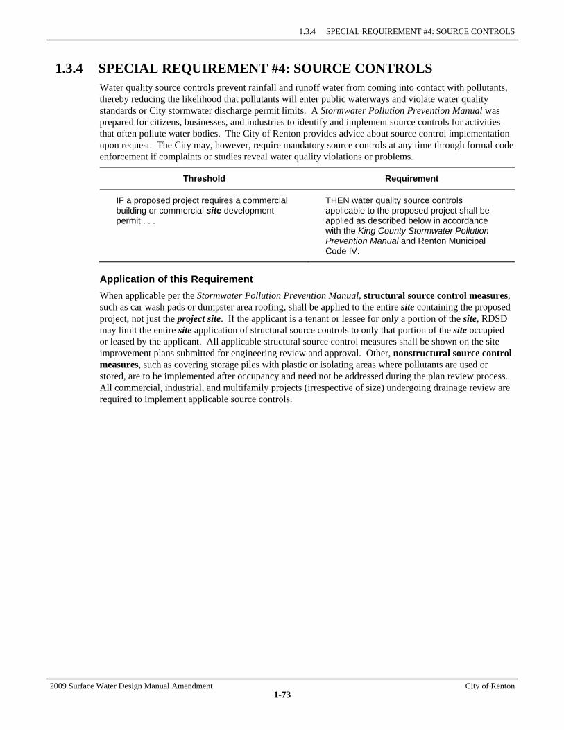
1.3.4 SPECIAL REQUIREMENT #4: SOURCE CONTROLS
2009 Surface Water Design Manual Amendment City of Renton
1-73
1.3.4 SPECIAL REQUIREMENT #4: SOURCE CONTROLS Water quality source controls prevent rainfall and runoff water from coming into contact with pollutants, thereby reducing the likelihood that pollutants will enter public waterways and violate water quality standards or City stormwater discharge permit limits. A Stormwater Pollution Prevention Manual was prepared for citizens, businesses, and industries to identify and implement source controls for activities that often pollute water bodies. The City of Renton provides advice about source control implementation upon request. The City may, however, require mandatory source controls at any time through formal code enforcement if complaints or studies reveal water quality violations or problems.
Threshold Requirement
IF a proposed project requires a commercial building or commercial site development permit . . .
THEN water quality source controls applicable to the proposed project shall be applied as described below in accordance with the King County Stormwater Pollution Prevention Manual and Renton Municipal Code IV.
Application of this Requirement When applicable per the Stormwater Pollution Prevention Manual, structural source control measures, such as car wash pads or dumpster area roofing, shall be applied to the entire site containing the proposed project, not just the project site. If the applicant is a tenant or lessee for only a portion of the site, RDSD may limit the entire site application of structural source controls to only that portion of the site occupied or leased by the applicant. All applicable structural source control measures shall be shown on the site improvement plans submitted for engineering review and approval. Other, nonstructural source control measures, such as covering storage piles with plastic or isolating areas where pollutants are used or stored, are to be implemented after occupancy and need not be addressed during the plan review process. All commercial, industrial, and multifamily projects (irrespective of size) undergoing drainage review are required to implement applicable source controls.
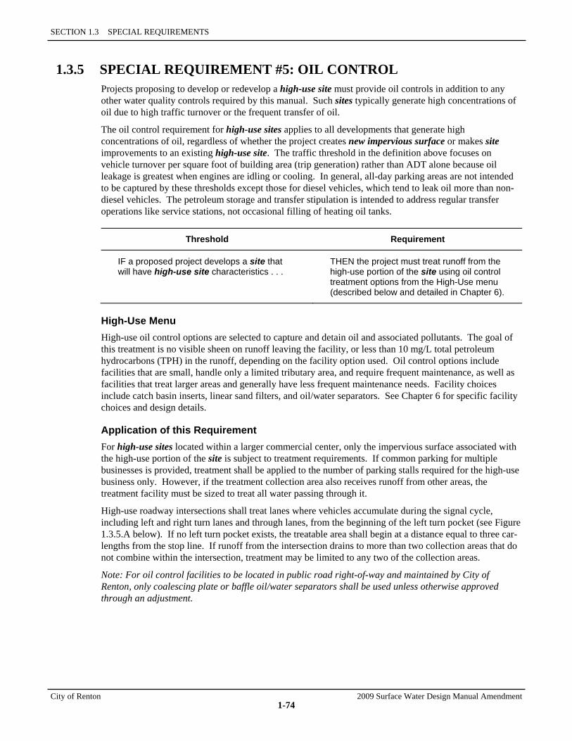
SECTION 1.3 SPECIAL REQUIREMENTS
City of Renton 2009 Surface Water Design Manual Amendment
1-74
1.3.5 SPECIAL REQUIREMENT #5: OIL CONTROL Projects proposing to develop or redevelop a high-use site must provide oil controls in addition to any other water quality controls required by this manual. Such sites typically generate high concentrations of oil due to high traffic turnover or the frequent transfer of oil.
The oil control requirement for high-use sites applies to all developments that generate high concentrations of oil, regardless of whether the project creates new impervious surface or makes site improvements to an existing high-use site. The traffic threshold in the definition above focuses on vehicle turnover per square foot of building area (trip generation) rather than ADT alone because oil leakage is greatest when engines are idling or cooling. In general, all-day parking areas are not intended to be captured by these thresholds except those for diesel vehicles, which tend to leak oil more than non-diesel vehicles. The petroleum storage and transfer stipulation is intended to address regular transfer operations like service stations, not occasional filling of heating oil tanks.
Threshold Requirement
IF a proposed project develops a site that will have high-use site characteristics . . .
THEN the project must treat runoff from the high-use portion of the site using oil control treatment options from the High-Use menu (described below and detailed in Chapter 6).
High-Use Menu High-use oil control options are selected to capture and detain oil and associated pollutants. The goal of this treatment is no visible sheen on runoff leaving the facility, or less than 10 mg/L total petroleum hydrocarbons (TPH) in the runoff, depending on the facility option used. Oil control options include facilities that are small, handle only a limited tributary area, and require frequent maintenance, as well as facilities that treat larger areas and generally have less frequent maintenance needs. Facility choices include catch basin inserts, linear sand filters, and oil/water separators. See Chapter 6 for specific facility choices and design details.
Application of this Requirement For high-use sites located within a larger commercial center, only the impervious surface associated with the high-use portion of the site is subject to treatment requirements. If common parking for multiple businesses is provided, treatment shall be applied to the number of parking stalls required for the high-use business only. However, if the treatment collection area also receives runoff from other areas, the treatment facility must be sized to treat all water passing through it.
High-use roadway intersections shall treat lanes where vehicles accumulate during the signal cycle, including left and right turn lanes and through lanes, from the beginning of the left turn pocket (see Figure 1.3.5.A below). If no left turn pocket exists, the treatable area shall begin at a distance equal to three car-lengths from the stop line. If runoff from the intersection drains to more than two collection areas that do not combine within the intersection, treatment may be limited to any two of the collection areas.
Note: For oil control facilities to be located in public road right-of-way and maintained by City of Renton, only coalescing plate or baffle oil/water separators shall be used unless otherwise approved through an adjustment.
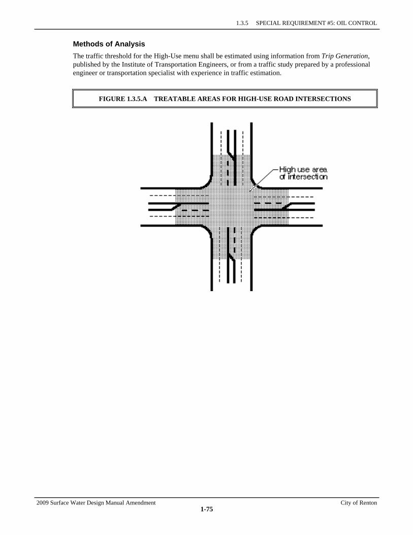
1.3.5 SPECIAL REQUIREMENT #5: OIL CONTROL
2009 Surface Water Design Manual Amendment City of Renton
1-75
Methods of Analysis The traffic threshold for the High-Use menu shall be estimated using information from Trip Generation, published by the Institute of Transportation Engineers, or from a traffic study prepared by a professional engineer or transportation specialist with experience in traffic estimation.
FIGURE 1.3.5.A TREATABLE AREAS FOR HIGH-USE ROAD INTERSECTIONS
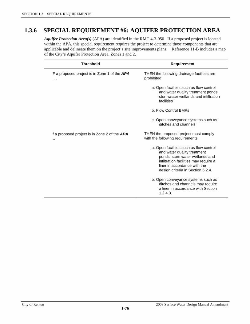
SECTION 1.3 SPECIAL REQUIREMENTS
City of Renton 2009 Surface Water Design Manual Amendment
1-76
1.3.6 SPECIAL REQUIREMENT #6: AQUIFER PROTECTION AREA Aquifer Protection Area(s) (APA) are identified in the RMC 4-3-050. If a proposed project is located within the APA, this special requirement requires the project to determine those components that are applicable and delineate them on the project’s site improvements plans. Reference 11-B includes a map of the City’s Aquifer Protection Area, Zones 1 and 2.
Threshold Requirement
IF a proposed project is in Zone 1 of the APA . . .
If a proposed project is in Zone 2 of the APA …
THEN the following drainage facilities are prohibited:
a. Open facilities such as flow control and water quality treatment ponds, stormwater wetlands and infiltration facilities
b. Flow Control BMPs
c. Open conveyance systems such as ditches and channels
THEN the proposed project must comply with the following requirements
a. Open facilities such as flow control and water quality treatment ponds, stormwater wetlands and infiltration facilities may require a liner in accordance with the design criteria in Section 6.2.4.
b. Open conveyance systems such as ditches and channels may require a liner in accordance with Section 1.2.4.3.
2009 Surface Water Design Manual Amendment City of Renton
1-77
1.4 ADJUSTMENT PROCESS For proposed projects subject to drainage review by the RDSD, this process is provided for the occasions when a project proponent desires to vary from one of the core or special requirements, or any other specific requirement or standard contained in this manual. Proposed adjustments shall be approved prior to final permit approval.
1.4.1 ADJUSTMENT AUTHORITY The Renton Development Service Division (RDSD) shall have full authority to determine if an adjustment is required for any proposed project subject to drainage review by RDSD. RDSD shall have full authority to approve or deny the adjustment.
1.4.2 VARIANCE AUTHORITY The Community and Economic Development Administrator or designee shall have the authority to grant variances from the provisions of those sections described in RMC 4-9-250B.
1.4.3 CRITERIA FOR GRANTING ADJUSTMENTS Adjustments to the Core Requirements and Special Requirements of this manual may be granted by the City provided that a written request is prepared, that addresses the following:
1. Produce a compensating or comparable result that is in the public interest, AND
2. Meet the objectives of safety, function, appearance, environmental protection, and maintainability based on sound engineering judgment.
Also, the granting of any adjustment that would be in conflict with the requirements of any other City department will require review and concurrence with that department.
1.4.4 CRITERIA FOR GRANTING VARIANCES If it can be demonstrated that meeting the above criteria for producing a compensating or comparable result will deny reasonable use of a property, a variance to the minimum requirements may be granted by the Community and Economic Development Administrator or designee following legal public notice per RMC 4-10 of the variance application, the Community and Economic Development Administrator or designee proposed decision on the application, and a written finding of fact that documents the following:
1. There are special physical circumstances or conditions affecting the property such that strict application of the criteria for producing a compensating or comparable result would deprive the applicant of all reasonable use of the parcel of land in question, and every effort has been made to find creative ways to meet the intent of the requirement for which the variance is sought, AND
2. Granting the variance for the individual property in question will not create a significant adverse impact to public health, welfare, water quality, and properties downstream or nearby, AND
3. The variance requires the best practicable alternative for achieving the spirit and intent of the requirement in question.
In addition, the written finding of fact must include the following information as required by the state Department of Ecology per the 2007 Phase II NPDES General Municipal Stormwater Permit:
• The current (pre-project) use of the site.
SECTION 1.4 ADJUSTMENT PROCESS
City of Renton 2009 Surface Water Design Manual Amendment
1-78
• How application of the requirements in the 2009 Surface Water Design Manual for which a variance is being requested denies all reasonable use of site compared to the development review conditions and restrictions that would have been placed on the project prior to the adoption of the 2009 Surface Water Design Manual.
• The possible remaining uses of the site if the variance was not granted.
• The uses of the site that would have been allowed under development review conditions and restrictions that would have been placed on the project prior to the adoption of the 2009 Surface Water Design Manual.
• A comparison of the estimated amount and percentage of value loss as a result of the requirements of this manual versus the estimated amount and percentage of value loss as a result of conditions restrictions that would have been placed on the project prior to the adoption of the 2009 Surface Water Design Manual.
• The feasibility for the owner to alter the project to apply the requirements of this manual.
1.4.5 ADJUSTMENT/VARIANCE APPLICATION PROCESS The application process for adjustments and variances is as follows:
• Requests for adjustments and variances will be accepted only for permits pending approval or approved permits that have not yet expired.
• Sufficient engineering information (described in Chapter 2) must be submitted to RDSD to evaluate the request in concordance with SWU. The application shall note the specific requirement for which the adjustment is sought.
• If the adjustment request involves use of a previously unapproved construction material or construction practice, the applicant should submit documentation that includes, but is not limited to, a record of successful use by other agencies and/or evidence of meeting criteria for quality and performance, such as that for the American Association of State Highway and Transportation Officials (AASHTO) and the American Society of Testing and Materials (ASTM).
1.4.6 APPEALS Any appeals from administrative determinations for variances or adjustments related to the Storm Drainage regulations and codes shall be filed in writing to the Hearing Examiner by any person aggrieved, or by any officer, department, board or bureau of the City affected by such determination per RMC 4-8-110.
2009 Surface Water Design Manual Amendment City of Renton
CHAPTER 2 DRAINAGE PLAN SUBMITTAL
CITY OF RENTON AMENDMENTS TO THE KING COUNTY SURFACE WATER DESIGN MANUAL February 2010
Section 2.1 Plans for Permits and Drainage Review
2-2
Section 2.1.1 Plans Required for Permit Pre-App Submittal
2-2
Section 2.1.2 Site Plans Submittal for Drainage Review
2-3
Section 2.2 Plans Required with Initial Utility Construction Permit Application
2-5
Section 2.3 Plans Required for Drainage Review
2-7
Section 2.3.1 Engineering Plan Specifications
2-7
Section 2.3.2 Projects in Targeted Drainage Review
2-34
Section 2.4 Plans Required After Drainage Review
2-35
Section 2.4.1 Plan Changes After Drainage Review Approval
2-35
Section 2.4.2 Final As Built Corrected Drawing Submittal
2-35

2009 Surface Water Design Manual Amendment City of Renton
2-1
CHAPTER 2 DRAINAGE PLAN SUBMITTAL
This chapter details the drainage related submittal requirements for engineering design plans as part of a permit application to the Renton Development Service Division (RDSD). The intent of these requirements is to present consistent formats for design plans and the technical support data required to develop the plans. These conventions are necessary to review engineering designs for compliance with City of Renton ordinances and regulations, and to ensure the intent of the plan is easily understood and implemented in the field. Properly drafted design plans and supporting information also facilitate the construction, operation, and maintenance of the proposed system long after its review and approval. When plans comply with the formats and specifications contained herein, they facilitate review and approval with a minimum of time-consuming corrections and resubmittals.
Note that this chapter primarily describes how to submit drainage plans for review—what must be submitted, in what formats, at what times and to what departments or divisions. The basic drainage requirements that these plans must address are contained in Chapter 1, "Drainage Review and Requirements." The specific design methods and criteria to be used are contained in Chapters 3, 4, 5, and 6.
Several key forms used in the plan review process are reproduced in Reference Section 8 of the Surface Water Design Manual, "Forms and Worksheets." The drainage submittal requirements for different types of developments are contained in this chapter with the exception of Master Drainage Plans, which If required, the scope of the requirements will be determined by the Surface Water Utility and will generally follow King County’s Master Drainage Planning for Large or Complex Site Development and requirements. For information on general requirements for any permit type refer to the customer information counter by RDSD.
Chapter Organization The information presented in this chapter is organized into four main sections as follows:
• Section 2.1, "Plans for Permits and Drainage Review"
• Section 2.2, "Plans Required with Initial Utility Construction Permit Application"
• Section 2.3, "Plans Required for Drainage Review "
• Section 2.4, "Plans Required After Drainage Review"
2009 Surface Water Design Manual Amendment City of Renton
2-2
2.1 PLANS FOR PERMITS AND DRAINAGE REVIEW RDSD is responsible for the review of all engineering aspects of private development proposals. Drainage review is a primary concern of engineering design. This section describes the types of engineered drainage plans and analysis required for drainage review. Detailed requirements are presented in sections 2.2 and 2.3.
2.1.1 PLANS REQUIRED FOR PERMIT PRE-APP SUBMITTAL Most projects require some degree of drainage plans or analysis to be submitted with the pre-application meeting request. At the City of Renton, subdivisions, PUD’s, shortplats and binding site plans will require preliminary plans (may be engineered or not engineered) be submitted with the initial permit application. Preliminary plans provide general information on the proposal, including location of critical areas, road alignments and right-of-way, site topography, building locations, land use information, and lot dimensions. They are used to determine the appropriate drainage conditions and requirements to be applied to the proposal during the drainage review process.
For more information refer to the permit submittal requirements documents that are applicable to the development proposal (available in the City’s website and from staff in the pre-application meeting).
2.1.2 SITE PLANS SUBMITTAL FOR DRAINAGE REVIEW
2009 Surface Water Design Manual Amendment City of Renton
2-3
2.1.2 SITE PLANS SUBMITTAL FOR DRAINAGE REVIEW For drainage review purposes, engineering plans consist of the following:
1. Site improvement plans (see Section 2.3.1.2), which include all plans, profiles, details, notes, and specifications necessary to construct road, drainage, and off-street parking improvements.
2. A construction stormwater pollution prevention plan (CSWPPP), which identifies the measures and BMPs required to prevent the discharge of sediment-laden water and other pollutants associated with construction/land disturbing activities. The CSWPPP includes two component plans: an erosion and sediment control (ESC) plan (see Section 2.3.1.3), which addresses prevention of sediment-laden discharges; and a stormwater pollution prevention and spill (SWPPS) plan (see Section 2.3.1.4), which addresses prevention of other pollutant discharges.
3. A technical information report (TIR) (see Section 2.3.1.1), which contains all the technical information and analysis necessary to develop the site improvement plan and CSWPPP.
Projects under Targeted Drainage Review usually require engineering plans, except that only certain sections of the technical information report are required to be completed and the site improvement plan may have a limited scope depending upon the characteristics of the proposed project. The scope of these plans should be confirmed during the pre-application meeting with RDSD. For other permits, such as single family residential permits, the scope of the targeted engineering analysis is usually determined during RDSD engineering review.
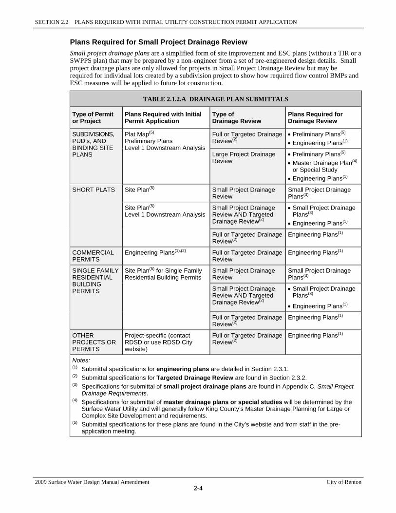
SECTION 2.2 PLANS REQUIRED WITH INITIAL UTILITY CONSTRUCTION PERMIT APPLICATION
2009 Surface Water Design Manual Amendment City of Renton
2-4
Plans Required for Small Project Drainage Review Small project drainage plans are a simplified form of site improvement and ESC plans (without a TIR or a SWPPS plan) that may be prepared by a non-engineer from a set of pre-engineered design details. Small project drainage plans are only allowed for projects in Small Project Drainage Review but may be required for individual lots created by a subdivision project to show how required flow control BMPs and ESC measures will be applied to future lot construction.
TABLE 2.1.2.A DRAINAGE PLAN SUBMITTALS
Type of Permit or Project
Plans Required with Initial Permit Application
Type of Drainage Review
Plans Required for Drainage Review
SUBDIVISIONS, PUD’s, AND BINDING SITE PLANS
Plat Map(5) Preliminary Plans Level 1 Downstream Analysis
Full or Targeted Drainage Review(2)
• Preliminary Plans(5) • Engineering Plans(1)
Large Project Drainage Review
• Preliminary Plans(5) • Master Drainage Plan(4)
or Special Study • Engineering Plans(1)
SHORT PLATS Site Plan(5)
Small Project Drainage Review
Small Project Drainage Plans(3)
Site Plan(5) Level 1 Downstream Analysis
Small Project Drainage Review AND Targeted Drainage Review(2)
• Small Project Drainage Plans(3)
• Engineering Plans(1)
Full or Targeted Drainage Review(2)
Engineering Plans(1)
COMMERCIAL PERMITS
Engineering Plans(1),(2) Full or Targeted Drainage Review
Engineering Plans(1)
SINGLE FAMILY RESIDENTIAL BUILDING PERMITS
Site Plan(5) for Single Family Residential Building Permits
Small Project Drainage Review
Small Project Drainage Plans(3)
Small Project Drainage Review AND Targeted Drainage Review(2)
• Small Project Drainage Plans(3)
• Engineering Plans(1)
Full or Targeted Drainage Review(2)
Engineering Plans(1)
OTHER PROJECTS OR PERMITS
Project-specific (contact RDSD or use RDSD City website)
Full or Targeted Drainage Review(2)
Engineering Plans(1)
Notes: (1) Submittal specifications for engineering plans are detailed in Section 2.3.1. (2) Submittal specifications for Targeted Drainage Review are found in Section 2.3.2. (3) Specifications for submittal of small project drainage plans are found in Appendix C, Small Project
Drainage Requirements. (4) Specifications for submittal of master drainage plans or special studies will be determined by the
Surface Water Utility and will generally follow King County’s Master Drainage Planning for Large or Complex Site Development and requirements.
(5) Submittal specifications for these plans are found in the City’s website and from staff in the pre-application meeting.

2009 Surface Water Design Manual Amendment City of Renton
2-5
2.2 PLANS REQUIRED WITH INITIAL UTILITY CONSTRUCTION PERMIT APPLICATION
This section describes the submittal requirements for initial construction permit applications at the City of Renton. For commercial, subdivisions, short plats, and other types of construction permits, this submittal usually follows the City's approval of plans described in section 2.1.2. For other permit types, the drainage plan requirements are determined during the permit review process.
Design Plan Certification All plans and engineering plans must be stamped by a civil engineer.
All land boundary surveys and legal descriptions used for preliminary and engineering plans must be stamped by a land surveyor licensed in the State of Washington. Topographic survey data and mapping prepared specifically for a proposed project may be performed by the civil engineer stamping the engineering plans as allowed by the Washington State Board of Registration for Professional Engineers and Land Surveyors.

2009 Surface Water Design Manual Amendment City of Renton
2-7
2.3 PLANS REQUIRED FOR DRAINAGE REVIEW This section presents the specifications and contents required of plans to facilitate drainage review. Most projects subject to Full Drainage Review will require engineering plans that include a "technical information report (TIR)," "site improvement plans," and a "construction stormwater pollution prevention plan (CSWPPP)," which includes an "erosion and sediment control (ESC) plan" and a "stormwater pollution prevention and spill (SWPPS) plan." In addition, a "landscape management plan" may also be required to comply with Core Requirement #8 (see Section 1.2.8). For more information on the types of projects subject to Full Drainage Review, see Section 1.1.2.3 More information is available at the City’s website and from the staff in the pre-application meeting. Small projects with specific drainage concerns that are subject to Targeted Drainage Review also require engineering plans that include the same elements, except that the TIR may be of limited scope. The site improvement plans, ESC and CSWPP plans may also be of limited scope, but must meet all applicable specifications. For more information on the types of projects subject to Targeted Drainage Review, see Section 1.1.2.2.
Projects subject to Small Project Drainage Review may be required to submit "small project drainage plans." These are simplified drainage and erosion control plans that may be prepared by a non-engineer from a set of pre-engineered design details, and which do not require a TIR or a SWPPS plan. The Small Project Drainage Requirements booklet available at King County Department of Development and Environmental Services and appended to the King County Surface Water Design Manual Manual (Appendix C) contains the specifications for small project drainage plans and details on the Small Project Drainage Review process.
Note: Projects in Small Project Drainage Review may be required to submit engineering plans if they are also subject to Targeted Drainage Review as determined in Section 1.1.2.2 and Appendix C of the King County Surface Water Design Manual. Also, short plats in Small Project Drainage Review will be required to submit engineering plans if roadway construction is a condition of preliminary approval.
Design Plan Certification All preliminary plans and engineering plans must be stamped by a civil engineer registered in the State of Washington.
All land boundary surveys, and legal descriptions used for preliminary and engineering plans must be stamped by a land surveyor licensed in the State of Washington. Topographic survey data and mapping prepared specifically for a proposed project may be performed by the licensed civil engineer stamping the engineering plans as allowed by the Washington State Board of Registration for Professional Engineers and Land Surveyors.
2.3.1 ENGINEERING PLAN SPECIFICATIONS For drainage review purposes, engineering plans must consist of the following:
1. A technical information report (TIR) as detailed in Section 2.3.1.1, AND
2. Site improvement plans as detailed in Section 2.3.1.2, AND
3. A CSWPPP, which includes an ESC plan as detailed in Section 2.3.1.3 and a SWPPS plan as detailed in Section 2.3.1.4.
Also, if applicable per Section 1.2.8, a landscape management plan, as detailed in Section 2.3.1.5, must be included.
Projects in Targeted Drainage Review require a limited scope TIR with site improvement plans and an ESC plan, as detailed in Section 2.3.2. RDSD may allow a modified site improvement plan for some projects in Targeted Drainage Review (see Section 2.3.2) or where major improvements (e.g., detention facilities, conveyance systems, bridges, road right-of-way improvements, etc.) are not proposed.
SECTION 2.3 PLANS REQUIRED FOR DRAINAGE REVIEW
2009 Surface Water Design Manual Amendment City of Renton
2-8
2.3.1.1 TECHNICAL INFORMATION REPORT (TIR) The full TIR should be a comprehensive supplemental report containing all technical information and analysis necessary to develop the site improvement plan. This report should contain all calculations, conceptual design analysis, reports, and studies required and used to construct a complete site improvement plan based on sound engineering practices and careful geotechnical and hydrological design. The TIR must be stamped and dated by a civil engineer.
The TIR shall contain the following ten sections, preceded by a table of contents:
1. Project Overview
2. Conditions and Requirements Summary
3. Offsite Analysis
4. Flow Control and Water Quality Facility Analysis and Design
5. Conveyance System Analysis and Design
6. Special Reports and Studies
7. Other Permits
8. CSWPPP Analysis and Design
9. Bond Quantities, Facility Summaries, and Declaration of Covenant
10. Operations and Maintenance Manual.
Every TIR must contain each of these sections; however, if a section does not apply, the applicant may simply mark "N/A" with a brief explanation. This standardized format allows a quicker, more efficient review of information required to supplement the site improvement plan.
The table of contents should include a list of the ten section headings and their respective page numbers, a list of tables with page numbers, and a list of numbered references, attachments, and appendices.
When the TIR package requires revisions, the revisions must be submitted in a complete TIR package.
TIR SECTION 1 PROJECT OVERVIEW The project overview must provide a general description of the proposal, predeveloped and developed site conditions, site and project site area, size of the improvements, and the disposition of stormwater runoff before and after development. The overview shall identify and discuss difficult site parameters, the natural drainage system, and drainage to and from adjacent property, including bypass flows.
The following figures are required:
Figure 1. TIR Worksheet Include a copy of the TIR Worksheet (see Reference Section 8-A) of the King County Surface Water Design Manual.
Figure 2. Site Location Provide a map that shows the general location of the site. Identify all roads that border the site and all significant geographic features and critical areas including lakes, wetlands, closed depressions, streams, steep slopes, hazard areas and any other critical areas.
Figure 3. Drainage Basins, Subbasins, and Site Characteristics This figure shall display the following:
1. Show acreage and boundaries of subbasins.
2. Identify all site characteristics.
2.3.1 ENGINEERING PLAN SPECIFICATIONS ⎯ TIR
2009 Surface Water Design Manual Amendment City of Renton
2-9
3. Show existing discharge points to and from the site.
4. Show routes of existing, construction, and future flows at all discharge points and downstream hydraulic structures.
5. Topographic map as a base for the figure comparable to USGS or better. Show (and cite) the length of travel from the farthest upstream end of a proposed storm system in the development to any proposed flow control facility.
Figure 4. Soils Show the soils within the following areas:
1. The project site
2. The area draining to the site
3. The drainage system downstream of the site for the distance of the downstream analysis (see Section 1.2.2).
Copies of King County Soil Survey maps may be used; however, if the maps do not accurately represent the soils for a proposed project (including offsite areas of concern), it is the design engineer's responsibility to ensure that the actual soil types are properly mapped. Soil classification symbols that conform to the SCS Soil Survey for King County shall be used; and the equivalent KCRTS soil type (till, outwash, or wetlands) shall be indicated (see Table 3.2.2.B).
Projects may need to evaluate the soils on each lot for applicability of the full infiltration flow control BMP as specified in Section 5.2. Single family residential projects must evaluate onsite soils for suitability for roof downspout infiltration as detailed in appendix C of the King County Surface Water Design Manual. This soils report, as well as geotechnical investigations necessary for proposed infiltration facilities, should be referenced in the TIR Overview and submitted under Special Reports and Studies, TIR Section VI. A figure in the required geotechnical report that meets the above requirements may be referenced to satisfy 1, 2, and 3 above.
TIR SECTION 2 CONDITIONS AND REQUIREMENTS SUMMARY The intent of this section is to ensure all preliminary approval conditions and applicable requirements pertaining to site engineering issues have been addressed in the site improvement plan. All conditions and requirements for the proposed project should be included.
In addition to the core requirements of this manual, adopted basin plans and other plans as listed in Special Requirement #1 should be reviewed and applicable requirements noted. Critical area requirements, conditions of plat approval, and conditions associated with development requirements (e.g., conditional use permits, rezones, variances and adjustments, SEPA mitigations, etc.) should also be included.
TIR SECTION 3 OFFSITE ANALYSIS All projects in engineering review shall complete, at a minimum, an Offsite Analysis, except for projects meeting the exemptions outlined in Section 1.2.2. The Offsite Analysis is usually completed as part of the initial permit application and review process, and is to be included in the TIR. Note: If offsite conditions have been altered since the initial submittal, a new offsite analysis may be required.
The primary component of the offsite analysis is the downstream analysis described in detail below. Upstream areas are included in this component to the extent they are expected to be affected by backwater effects from the proposed project. Other components of the offsite analysis could include, but are not limited to, evaluation of impacts to fish habitat, groundwater levels, groundwater quality, or other environmental features expected to be significantly impacted by the proposed project due to its size or proximity to such features.
SECTION 2.3 PLANS REQUIRED FOR DRAINAGE REVIEW
2009 Surface Water Design Manual Amendment City of Renton
2-10
Levels of Analysis The offsite analysis report requirements vary depending on the specific site and downstream conditions. Each project submittal shall include at least a Level 1 downstream analysis. Upon review of the Level 1 analysis, RDSD may require a Level 2 or Level 3 analysis. If conditions warrant, additional, more detailed analysis may be required. Note: Potential impacts upstream of the proposal shall also be evaluated.
Level 1 Analysis The Level 1 analysis is a qualitative survey of each downstream system leaving a site. This analysis is required for all proposed projects and shall be submitted with the initial permit application. Depending on the findings of the Level 1 analysis, a Level 2 or 3 analysis may need to be completed or additional information may be required. If further analysis is required, the applicant may schedule a meeting with RDSD staff.
Level 2 or 3 Analysis If problems are identified in the Level 1 analysis, a Level 2 (rough quantitative) analysis or a Level 3 (more precise quantitative) analysis may be required to further evaluate proposed mitigation for the problem. RDSD staff will determine whether a Level 2 or 3 analysis is required based on the evidence of existing or potential drainage problems identified in the Level 1 analysis and on the proposed design of onsite drainage facilities. The Level 3 analysis is required when results need to be as accurate as possible: for example, if the site is flat; if the system is affected by downstream controls; if minor changes in the drainage system could flood roads or buildings; or if the proposed project will contribute more than 15 percent of the total peak flow to the drainage problem location.
Additional Analysis Additional, more detailed hydrologic analysis may be required if RDSD determines that the downstream analysis has not been sufficient to accurately determine the impacts of a proposed project on an existing or potential drainage problem. This more detailed analysis may include a point of compliance analysis as detailed in Section 3.3.6.
Scope of Analysis Regardless of the level of downstream analysis required, the applicant shall define and map the study area (Task 1), review resources (Task 2), inspect the study area (Task 3), describe the drainage system and problems (Task 4), and propose mitigation measures (Task 5) as described below.
Task 1. Study Area Definition and Maps For the purposes of Task 2 below, the study area shall extend downstream one mile (minimum flowpath distance) from the proposed project discharge location and shall extend upstream as necessary to encompass the offsite drainage area tributary to the proposed project site. For the purposes of Tasks 3, 4, and 5, the study area shall extend downstream to a point on the drainage system where the proposed project site constitutes less than 15 percent of the total tributary drainage area, but not less than one-quarter mile (minimum flowpath distance). The study area shall also extend upstream of the project site a distance sufficient to preclude any backwater effects from the proposed project.
The offsite analysis shall include a site map showing property lines, and the best available topographical map (e.g., from RDSD and Renton Topographic map) with the study area boundaries, site boundaries, downstream flowpath for a distance of one mile, and potential/existing problems (Task 4) shown. Other maps, diagrams, photographs and aerial photos may be helpful in describing the study area.
Task 2. Resource Review To assist the design engineer in preparing an offsite analysis, Renton has gathered information regarding existing and potential flooding and erosion. For all levels of analysis, all of the resources
2.3.1 ENGINEERING PLAN SPECIFICATIONS ⎯ TIR
2009 Surface Water Design Manual Amendment City of Renton
2-11
described below shall be reviewed for existing/potential problems in the study area (upstream and one mile downstream of the project site):
• Adopted basin plans available at King County DDES, King County DNRP, and RDSD. For areas where there is no adopted basin plan, Basin Reconnaissance Summary Reports may be useful.
• Floodplain/floodway (FEMA) maps available at RDSD and the library.
• Other offsite analysis reports in the same subbasin, if available (check with RDSD records staff).
• Sensitive Areas Folio available at King County DDES, King County DNRP, and the library (see also the City website: http://rentonnet.org/internetapps/maps/index.cfm?fuseaction=products) must be used to document the distance downstream from the proposed project to the nearest critical areas.
• U.S. Department of Agriculture, King County Soils Survey available at King County DDES and the library.
• Wetlands Inventory maps available at RDSD.
• Washington State Department of Ecology's latest published Clean Water Act Section 303d list of polluted waters posted at the following website: http://apps.ecy.wa.gov/wqawa/viewer.htm.
• City of Renton Erosion Maps and Landslide Maps.
Potential/existing problems identified in the above documents shall be documented in the Drainage System Table (see Reference Section 8-B) as well as described in the text of the Level 1 Downstream Analysis Report. If a document is not available for the site, note in the report that the information was not available as of a particular date. If necessary, additional resources are available from King County, the Washington State Department of Fisheries and Wildlife (WDFW), the State Department of Ecology (DOE), the United States Army Corps of Engineers (Corps), and the public works departments of other municipalities and utility districts in the vicinity of the proposed project site.
Task 3. Field Inspection The design engineer shall physically inspect the existing on- and offsite drainage systems of the study area for each discharge location. Specifically, he/she shall investigate any evidence of the following existing or potential problems and drainage features:
Level 1 Inspection: 1. Investigate any problems reported or observed during the resource review.
2. Locate all existing/potential constrictions or lack of capacity in the existing drainage system.
3. Identify all existing/potential downstream drainage problems as defined in Section 1.2.2.1.
4. Identify existing/potential overtopping, scouring, bank sloughing, or sedimentation.
5. Identify significant destruction of aquatic habitat or organisms (e.g., severe siltation, bank erosion, or incision in a stream).
6. Collect qualitative data on features such as land use, impervious surfaces, topography, and soil types.
7. Collect information on pipe sizes, channel characteristics, drainage structures, and relevant critical areas (e.g., wetlands, streams, steep slopes).
8. Verify tributary basins delineated in Task 1.
9. Contact neighboring property owners or residents in the area about past or existing drainage problems, and describe these in the report (optional).
10. Note the date and weather conditions at the time of the inspection.
SECTION 2.3 PLANS REQUIRED FOR DRAINAGE REVIEW
2009 Surface Water Design Manual Amendment City of Renton
2-12
Level 2 or 3 Inspection: 1. Perform a Level 1 Inspection.
2. Document existing site conditions (approved drainage systems or pre-1979 aerial photographs) as defined in Core Requirement #3.
3. Collect quantitative field data. For Level 2, conduct rough field survey using hand tape, hand level, and rod; for Level 3, collect field survey profile and cross-section topographic data prepared by an experienced surveyor.
Task 4. Drainage System Description and Problem Descriptions Each drainage system component and problem shall be addressed in the offsite analysis report in three places: on a map (Task 1), in the narrative (Task 4), and in the Offsite Analysis Drainage System Table (see Reference Section 8-B).
Drainage System Descriptions: The following information about drainage system components such as pipes, culverts, bridges, outfalls, ponds, tanks, and vaults shall be included in the report:
1. Location (corresponding map label and distance downstream/upstream from site discharge)
2. Physical description (type, size, length, slope, vegetation, and land cover)
3. Problems including copies of any relevant drainage complaints
4. Field observations.
Problem Descriptions: All existing or potential problems (e.g., ponding water, high/low flows, siltation, erosion, listed water bodies, etc.) identified in the resource review or field inspection shall be described in the offsite analysis. These descriptions will help in determining if such problems require special attention per Core Requirement #2 (see Section 1.2.2.1).because they are one of three defined drainage problem types . Special attention may include more analysis, additional flow control, or other onsite or offsite mitigation measures as specified by the problem-specific mitigation requirements set forth in Sections 1.2.2.2 and 1.2.2.3.
The following information shall be provided for each existing or potential problem:
1. Description of the problem (ponding water, high or low flows, siltation, erosion, slides, etc.).
2. Magnitude of or damage caused by the drainage problem (siltation of ponds, dried-up ornamental ponds, road inundation, flooded property, flooded building, flooded septic system, significant destruction of aquatic habitat or organisms).
3. General frequency and duration of drainage problem (dates and times the problem occurred, if available).
4. Return frequency of storm or flow (cfs) of the water when the problem occurs (optional for Level 1 and required for Levels 2 and 3). Note: A Level 2 or 3 analysis may be required to accurately identify the return frequency of a particular downstream problem; see Section 3.3.3.
5. Water surface elevation when the problem occurs (e.g., elevation of building foundation, crest of roadway, elevation of septic drainfields, or wetland/stream high water mark).
6. Names and concerns of involved parties (optional for all levels of analysis).
7. Current mitigation of the drainage problem.
8. Possible cause of the drainage problem.
2.3.1 ENGINEERING PLAN SPECIFICATIONS ⎯ TIR
2009 Surface Water Design Manual Amendment City of Renton
2-13
9. Whether the proposed project is likely to aggravate (increase the frequency or severity of) the existing drainage problem or create a new one based on the above information. See Section 1.2.3.1 for more details on the effectiveness of flow control standards in addressing downstream problems.
10. Major receiving water bodies.
Task 5. Mitigation of Existing or Potential Problems For any existing or potential offsite drainage problem determined to be one of the three defined problem types in Section 1.2.2.1, the design engineer must demonstrate that the proposed project neither aggravates (if existing) nor creates the problem as specified in the drainage problem-specific mitigation requirements set forth in Section 1.2.2.2. The engineer must review each relevant drainage complaint found and include a narrative explaining how each complaint problems is addressed or mitigated. Actual copies of the relevant complaints must be included in the Analysis. To meet these requirements, the proposed project may need to provide additional onsite flow control as specified in Table 1.2.3.A (see also Section 3.3.5), or other onsite or offsite mitigation measures as described in Section 3.3.5.
TIR SECTION 4 FLOW CONTROL AND WATER QUALITY FACILITY ANALYSIS AND DESIGN
Existing Site Hydrology (Part A) This section of the TIR should include a discussion of assumptions and site parameters used in analyzing the existing site hydrology.
The acreage, soil types, and land covers used to determine existing flow characteristics, along with basin maps, graphics, and exhibits for each subbasin affected by the development, should be included.
The following information must be provided on a topographical map:
1. Delineation and acreage of areas contributing runoff to the site
2. Flow control facility location
3. Outfall
4. Overflow route.
The scale of the map and the contour intervals must be sufficient to determine the basin and subbasin boundaries accurately. The direction of flow, the acreage of areas contributing drainage, and the limits of development should all be indicated on the map.
Each subbasin contained within or flowing through the site should be individually labeled and KCRTS parameters referenced to that subbasin.
All natural streams and drainage features, including wetlands and depressions, must be shown. Rivers, closed depressions, streams, lakes, and wetlands must have the 100-year floodplain (and floodway where applicable) delineated as required in Special Requirement #2 (see Section 1.3.2) and by the applicable critical areas requirements in RMC 4-3-050.
Developed Site Hydrology (Part B) This section should provide narrative, mathematical, and graphical presentations of parameters selected and values used for the developed site conditions, including acreage, soil types and land covers, roadway layouts, and all constructed drainage facilities and any required flow control BMPs.
Developed subbasin areas and flows should be clearly depicted on a map and cross-referenced to computer printouts or calculation sheets. Relevant portions of the calculations should be highlighted and tabulated in a listing of all developed subbasin flows.
All maps, exhibits, graphics, and references used to determine developed site hydrology must be included, maintaining the same subbasin labeling as used for the existing site hydrology whenever possible. If the

SECTION 2.3 PLANS REQUIRED FOR DRAINAGE REVIEW
2009 Surface Water Design Manual Amendment City of Renton
2-14
boundaries of the subbasin have been modified under the developed condition, the labeling should be modified accordingly (e.g., Subbasin "Am" is a modified version of existing Subbasin "A").
Performance Standards (Part C) The design engineer shall include brief discussions of the following:
• The applicable area-specific flow control facility standard determined from the City of Renton Flow Control Applications Map per Section 1.2.3.1, any modifications to the standard to address onsite or offsite drainage conditions, and applicable flow control BMP requirements determined from Sections 1.2.3.3 and 5.2;
• The applicable conveyance system capacity standards per Section 1.2.4; and
• The applicable land use-specific water quality requirement determined per Section 1.2.8.1, and any applicable special requirements for source control or oil control determined from Sections 1.3.4 and 1.3.5.
Flow Control System (Part D) This section requires an illustrative sketch of the flow control facility (or facilities), required flow control BMPs, and appurtenances. The facility sketch (or sketches) must show basic measurements necessary to calculate the storage volumes available from zero to the maximum head, all orifice/restrictor sizes and head relationships, control structure/restrictor orientation to the facility, and facility orientation on the site. The flow control BMP sketch (or sketches) must show basic measurements and dimensions, orientation on the site, flowpath lengths, etc.
The applicant should include all supporting documentation such as computer printouts, calculations, equations, references, storage/volume tables, graphs, and any other aides necessary to clearly show results and methodology used to determine the storage facility volumes. KCRTS facility documentation files, "Compare Flow Durations" files, peaks files, return frequency or duration curves, etc., shall be included to verify the facility meets the performance standards indicated in Part C. The volumetric safety factor used in the design should be clearly identified, as well as the reasoning used by the design engineer in selecting the safety factor for this project. If flow control BMP credits are used as allowed in Section 5.2.2, documentation must be provided, explaining how the credits will be used and how the criteria for use of credits will be met. If the flow control system is an infiltration facility, the soils data, groundwater mounding analysis, or other calculations used to determine the design infiltration rate shall be provided.
Water Quality System (Part E) This section provides an illustrative sketch of the proposed water quality facility (or facilities), source controls, oil controls, and appurtenances. This sketch (or sketches) of the facility, source controls, and oil controls must show basic measurements and dimensions, orientation on the site, location of inflow, bypass, and discharge systems, etc.
The applicant should include all supporting documentation such as computer printouts, calculations, equations, references, and graphs necessary to show the facility was designed and sized in accordance with the specifications and requirements in Chapter 6. If the water quality credit option is used as allowed in Section 6.1.2, documentation must be provided, identifying the actions that will be taken to acquire the requisite credits.
TIR SECTION 5 CONVEYANCE SYSTEM ANALYSIS AND DESIGN This section should present a detailed analysis of any existing conveyance systems, and the analysis and design of the proposed stormwater collection and conveyance system for the development. This section would also include any analysis required for the design of bridges to convey flows and pass sediments and debris per Section 4.4.3. Analysis information should be presented in a clear, concise manner that can be easily followed, checked, and verified. All pipes, culverts, catch basins, channels, swales, and other stormwater conveyance appurtenances must be clearly labeled and correspond directly to the engineering plans.
2.3.1 ENGINEERING PLAN SPECIFICATIONS ⎯ TIR
2009 Surface Water Design Manual Amendment City of Renton
2-15
The minimum information included shall be pipe flow tables, flow profile computation tables, nomographs, charts, graphs, detail drawings, and other tabular or graphic aides used to design and confirm performance of the conveyance system.
Verification of capacity and performance must be provided for each element of the conveyance system. The analysis must show design velocities and flows for all drainage facilities within the development, as well as those offsite that are affected by the development. If the final design results are on a computer printout, a separate summary tabulation of conveyance system performance should also be provided.
TIR SECTION 6 SPECIAL REPORTS AND STUDIES Some site characteristics, such as steep slopes or wetlands, pose unique road and drainage design problems that are particularly sensitive to stormwater runoff. As a result, Renton Surface Water Utility may require the preparation of special reports and studies that further address the site characteristics, the potential for impacts associated with the development, and the measures that would be implemented to mitigate impacts. Special reports shall be prepared by people with expertise in the particular area of analysis. Topics of special reports may include any of the following:
• Floodplain delineation in accordance with Section 1.3.2
• Flood protection facility conformance in accordance with Section 1.3.3
• Critical areas analysis and delineation
• Geotechnical/soils
• Groundwater
• Slope protection/stability
• Erosion and deposition
• Geology
• Hydrology
• Fluvial geomorphology
• Anadromous fisheries impacts
• Water quality
• Structural design
• Structural fill.
• Aquifer Protection Areas
TIR SECTION 7 OTHER PERMITS Construction of road and drainage facilities may require additional permits from other City Departments for some projects. These additional permits may contain more restrictive drainage plan requirements. This section of the TIR should provide the titles of any other permits, the agencies requiring the other permits, and the permit requirements that affect the drainage plan. Examples of other permits are listed in Section 1.1.3. If a UIC well registration is required, a copy must be provided.
TIR SECTION 8 CSWPPP ANALYSIS AND DESIGN This section of the TIR should include the analysis and design information used to prepare the required construction stormwater pollution prevention plan. This information should be presented in two parts associated with the CSWPPP's two component plans, the erosion sediment control (ESC) plan (Part A)
SECTION 2.3 PLANS REQUIRED FOR DRAINAGE REVIEW
2009 Surface Water Design Manual Amendment City of Renton
2-16
and the stormwater pollution prevention and spill (SWPPS) plan (Part B). See Sections 2.3.1.3 and 2.3.1.4 for plan specifications and contents.
ESC Plan Analysis and Design (Part A) This section must include all hydrologic and hydraulic information used to analyze and design the erosion and sediment control measures, including final site stabilization measures. The TIR shall explain how proposed ESC measures comply with the Erosion and Sediment Control Standards (detached Appendix D of the King County Surface Water Design Manual) and show compliance with the implementation requirements of Core Requirement #5, Section 1.2.5.
Part A must include the following:
1. Provide sufficient information to justify the overall ESC plan and the choice of individual ESC measures. At a minimum, there shall be a discussion of each of the measures specified in Section 1.2.5 and their applicability to the proposed project.
2. Include all hydrologic and hydraulic information used to analyze and size the ESC facilities shown in the engineering plans. Describe the methodology, and attach any graphics or sketches used to size the facilities.
3. Identify areas with a particularly high susceptibility to erosion because of slopes or soils. Discuss any special measures taken to protect these areas as well as any special measures proposed to protect water resources on or near the site.
4. Identify any ESC recommendations in any of the special reports prepared for the project. If these recommendations are not included in the ESC plan, provide justification.
5. If proposing exceptions or modifications to the standards detailed in the Erosion and Sediment Control Standards (detached Appendix D of the King County Surface Water Design Manual), clearly present the rationale. If proposing techniques or products different from those detailed in the ESC Standards, provide supporting documentation as specified in section 1.4 so the Renton Development Service can determine if the proposed alternatives provide similar protection.
SWPPS Plan Design (Part B) The stormwater pollution prevention and spill plan must identify all activities that could contribute pollutants to surface and storm water during construction. This section of the TIR must provide sufficient information to justify the selection of specific stormwater pollution prevention BMPs proposed to be applied to the pollution-generating activities that will occur with construction of the proposed project. BMPs applicable to such activities are found in the King County Stormwater Pollution Prevention Manual adopted pursuant to RMC 4-6-030.
At a minimum, there shall be a discussion of each anticipated pollution-generating activity and the pollution prevention BMPs selected to address it. If there are any calculations required for the selected BMP, include those in the discussion. If an alternative BMP or major modification to one of the County's standard BMPs will be used, a written request must be submitted for review and approval, detailing how the alternative will work. An "Alternative BMP Request Form" is available in the Stormwater Pollution Prevention Manual.
Updates or revisions to the SWPPS plan may be requested by RDSD at any time during project construction if RDSD determines that pollutants generated on the construction site have the potential to contaminate surface, storm, or ground water.
2.3.1 ENGINEERING PLAN SPECIFICATIONS ⎯ TIR
2009 Surface Water Design Manual Amendment City of Renton
2-17
TIR SECTION 9 BOND QUANTITIES, FACILITY SUMMARIES, AND DECLARATION OF COVENANT
Bond Quantities Worksheet Each plan submittal requires a construction quantity summary to establish appropriate bond amounts to meet the requirements of Core Requirement #7. Using the Bond Quantities Worksheet (see Reference 8-H), the design engineer shall separate existing right-of-way and erosion control quantities from other onsite improvements. In addition, the design engineer shall total the amounts based on the unit prices listed on the form.
Drainage facilities for single family residential building permits, which are normally not bonded, shall be constructed and approved prior to granting the certificate of occupancy.
Flow Control and Water Quality Facility Summary Sheet and Sketch Following approval of the plans, a Flow Control and Water Quality Facility Summary Sheet and Sketch (see Reference 8-D of the King County Surface Water Design Manual) shall be submitted along with an 81/2" x 11" plan sketch for each facility proposed for construction. The plan shall show a north arrow, the tract, the facility access road, the extent of the facility, and the control structure location. The approximate street address shall be noted.
Declaration of Covenant for Privately Maintained Flow Control and WQ Facilities Any declaration of covenant and grant of easement required for proposed flow control and water quality facilities per Section 1.2.6 must be included here for review and approval by RDSD before recording in King County. After approval by RDSD, the declaration of covenant and grant of easement must be signed and recorded at the office of King County Records and Elections before any permit is approved.
Declaration of Covenant for Privately Maintained Flow Control BMPs Any declarations of covenant and grant of easement required for proposed flow control BMPs per Section 5.2 must be included here for review and approval before recording. After approval by RDSD, all such documents must be signed and recorded with the City of Renton before any permit is approved.
TIR SECTION 10 OPERATIONS AND MAINTENANCE MANUAL For each flow control and water quality facility that is to be privately maintained, and for those that have special non-standard features, the design engineer shall prepare an operations and maintenance manual. The manual should be simply written and should contain a brief description of the facility, what it does, and how it works. In addition, the manual shall include a copy of the Maintenance Requirements for Flow Control, Conveyance, and WQ Facilities (see Appendix A of the King County Surface Water Design Manual) and provide an outline of maintenance tasks and the recommended frequency each task should be performed. This is especially important for water quality facilities where proper maintenance is critical to facility performance. For this reason, most of the water facility designs in Chapter 6 include "maintenance considerations" important to the performance of each facility.
SECTION 2.3 PLANS REQUIRED FOR DRAINAGE REVIEW
2009 Surface Water Design Manual Amendment City of Renton
2-18
2.3.1.2 SITE IMPROVEMENT PLAN Site improvement plans shall portray design concepts in a clear and concise manner. The plans must present all the information necessary for persons trained in engineering to review the plans, as well as those persons skilled in construction work to build the project according to the design engineer's intent. Supporting documentation for the site improvement plans must also be presented in an orderly and concise format that can be systematically reviewed and understood by others.
Survey Datum and Precision (RC) The horizontal component of all surveys shall have as its coordinate base: The North American Datum of 1983/91. All horizontal control for projects must be referenced to or in conjunction with a minimum of two of the City of Renton's Survey Control Network monuments. The source of the coordinate values used will be shown on the survey drawing per RCW 58.09.070. The horizontal component of all surveys shall meet or exceed the closure requirements of WAC 332-130-060. The control base lines for all surveys shall meet or exceed the requirements for a Class A survey revealed in Table 2 of the Minimum Standard Detail Requirements for ALTA/ACSM Land Title Surveys jointly established and adopted by ALTA and ACSM in 1992 or comparable classification in future editions of said document. The angular and linear closure and precision ratio of traverses used for survey control shall be revealed on the face of the survey drawing, as shall the method of adjustment. The horizontal component of the control system for surveys using global positioning system methodology shall exhibit at least 1 part in 50,000 precision in line length dependent error analysis at a 95 percent confidence level and performed pursuant to Federal Geodetic Control Subcommittee Standards for GPS control surveys as defined in Geometric Geodetic Accuracy Standards & Specifications for Using GPS Relative Positioning Techniques dated August 1, 1989 or comparable classification in future editions of said document.. The vertical component of all surveys shall be based on NAVD 1988, the North American Vertical Datum of 1988, and tied to at least one of the City of Renton Survey Control Network benchmarks. If there are two such benchmarks within 3000 feet of the project site a tie to both shall be made. The benchmark(s) used will be shown on the drawing. If a City of Renton benchmark does not exist within 3000 feet of a project, one must be set on or near the project in a permanent manner that will remain intact throughout the duration of the project. Source of elevations (benchmark) will be shown on the drawing, as well as a description of any bench marks established. See section 1-11.1(2) Drafting Standards.
The site improvement plans consist of all the plans, profiles, details, notes, and specifications necessary to construct road, drainage structure, and off-street parking improvements. Site improvement plans include the following:
• A base map (described on page 2-21), and
• Site plan and profiles (beginning on page 2-22).
Note: Site improvement plans must also include grading plans if onsite grading extends beyond the roadway.
Modified Site Improvement Plan RDSD may allow a modified site improvement plan for some projects in Targeted Drainage Review (see Section 2.3.2) or where major improvements (e.g., detention facilities, conveyance systems, bridges, road right-of-way improvements, etc.) are not proposed. The modified site improvement plan must:
1. Be drawn on a 11" x 17" or larger sheet,
2. Accurately locate structure(s) and access, showing observance of the setback requirements given in this manual, the critical areas regulations ( RMC 4-3-050), or other applicable documents,
3. Provide enough information (datum, topography, details, notes, etc.) to address issues as determined by RDSD.
GENERAL PLAN FORMAT Site improvement plans should use City of Renton Drafting Standards as appropriate, and must include Standard Plan Notes (see Reference Section 7). Each plan must follow the general format detailed below:
2.3.1 ENGINEERING PLAN SPECIFICATIONS ⎯ SITE IMPROVEMENT PLAN
2009 Surface Water Design Manual Amendment City of Renton
2-19
1. Plan sheets and profile sheets, or combined plan and profile sheets, specifications, and detail sheets as required shall be on 22 inch by 34 inch sheets. Right-of-way improvements must be on 22 inch by 34 inch sheets as referenced in the City of Renton Drafting Standards.
2. Drafting details shall generally conform to King County Standard Map Symbols (see Reference Section 7-A) with lettering size (before reduction) no smaller than Leroy 80 (Leroy 100 is preferred). Existing features shall be shown with dashed lines or as half-toned (screened) in order to clearly distinguish existing features from proposed improvements.
3. Each submittal shall contain a project information/cover sheet with the following:
a) Title: Project name and RDSD file number
b) Table of contents
c) Vicinity map
d) Name and phone number of utility field contacts (e.g., water, sanitary sewer, gas, power, telephone, and TV) and the One-Call number (1-800-424-5555)
e) Renton’s preconstruction/inspection notification requirements
f) Name and phone number of the erosion control supervisor
g) Name and phone number of the surveyor
h) Name and phone number of the owner/agent
i) Name and phone number of the applicant
j) Legal description
k) Plan approval signature block for RDSD
l) Name and phone number of the engineering firm preparing the plans (company logos acceptable)
m) Statement that mailbox locations have been designated or approved by the U.S. Postal Service (where required)
4. An overall site plan shall be included if more than three plan sheets are used. The overall plan shall be indexed to the detail plan sheets and include the following:
a) The complete property area development
b) Right-of-way information
c) Street names and road classification
d) All project phasing and proposed division boundaries
e) All natural and proposed drainage collection and conveyance systems with catch basin numbers shown.
5. Each sheet of the plan set shall be stamped, signed, and dated by a civil engineer registered in the State of Washington. At least one sheet showing all boundary survey information must be provided and stamped by a land surveyor licensed in the State of Washington.
6. Detail sheets shall provide sufficient information to construct complex elements of the plan. Details may be provided on plan and profile sheets if space allows.
7. A title block shall be provided on each plan sheet. At a minimum, the title block shall list the following:
a) Development title
b) Name, address, and phone number of the firm or individual preparing the plan
c) A revision block
SECTION 2.3 PLANS REQUIRED FOR DRAINAGE REVIEW
2009 Surface Water Design Manual Amendment City of Renton
2-20
d) Page (of pages) numbering
e) Sheet title (e.g., road and drainage, grading, erosion and sediment control).
8. A blank approval block shall be provided on each plan sheet. Two such blocks shall be provided on the first sheet of a plan set.
9. The location and label for each section or other detail shall be provided.
10. Critical areas, critical area buffers, and critical area building setbacks as required by critical area regulations RMC 4-3-050 shall be delineated and labeled.
11. All match lines with matched sheet number shall be provided.
12. All division or phase lines and the proposed limits of construction under the permit application shall be indicated.
13. Wetlands shall be labeled with the number from the City’s wetland inventory, or shall be labeled as "uninventoried" if not listed on the wetland inventory.
14. The standard plan notes that apply to the project shall be provided on the plans (see Reference Section 7-B of the Surface Water Design Manual).
15. Commercial building permit applications shall include the designated zoning for all properties adjacent to the development site(s).
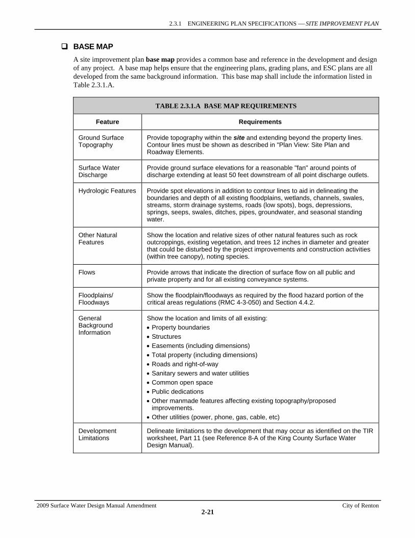
2.3.1 ENGINEERING PLAN SPECIFICATIONS ⎯ SITE IMPROVEMENT PLAN
2009 Surface Water Design Manual Amendment City of Renton
2-21
BASE MAP A site improvement plan base map provides a common base and reference in the development and design of any project. A base map helps ensure that the engineering plans, grading plans, and ESC plans are all developed from the same background information. This base map shall include the information listed in Table 2.3.1.A.
TABLE 2.3.1.A BASE MAP REQUIREMENTS
Feature Requirements
Ground Surface Topography
Provide topography within the site and extending beyond the property lines. Contour lines must be shown as described in "Plan View: Site Plan and Roadway Elements.
Surface Water Discharge
Provide ground surface elevations for a reasonable "fan" around points of discharge extending at least 50 feet downstream of all point discharge outlets.
Hydrologic Features Provide spot elevations in addition to contour lines to aid in delineating the boundaries and depth of all existing floodplains, wetlands, channels, swales, streams, storm drainage systems, roads (low spots), bogs, depressions, springs, seeps, swales, ditches, pipes, groundwater, and seasonal standing water.
Other Natural Features
Show the location and relative sizes of other natural features such as rock outcroppings, existing vegetation, and trees 12 inches in diameter and greater that could be disturbed by the project improvements and construction activities (within tree canopy), noting species.
Flows Provide arrows that indicate the direction of surface flow on all public and private property and for all existing conveyance systems.
Floodplains/ Floodways
Show the floodplain/floodways as required by the flood hazard portion of the critical areas regulations (RMC 4-3-050) and Section 4.4.2.
General Background Information
Show the location and limits of all existing: • Property boundaries • Structures • Easements (including dimensions) • Total property (including dimensions) • Roads and right-of-way • Sanitary sewers and water utilities • Common open space • Public dedications • Other manmade features affecting existing topography/proposed
improvements. • Other utilities (power, phone, gas, cable, etc)
Development Limitations
Delineate limitations to the development that may occur as identified on the TIR worksheet, Part 11 (see Reference 8-A of the King County Surface Water Design Manual).
SECTION 2.3 PLANS REQUIRED FOR DRAINAGE REVIEW
2009 Surface Water Design Manual Amendment City of Renton
2-22
SITE PLAN AND PROFILES The design engineer shall provide plans and profiles for all construction, including but not limited to the following information:
Plan View: Site Plan and Roadway Elements 1. Provide property lines, right-of-way lines, and widths for proposed roads and intersecting roads.
Note: the condition of all public right-of-way and the right to use it as proposed must be verified.
2. Provide all existing and proposed roadway features, such as centerlines, edges of pavement and shoulders, ditchlines, curbs, and sidewalks. In addition, show points of access to abutting properties and roadway continuations.
3. Show existing and proposed topography contours at 2-foot intervals (5-foot intervals for slopes greater than 15 percent, 10-foot intervals for slopes greater than 40 percent). Contours may be extrapolated from USGS mapping, aerial photos, or other topography map resources. However, contours shall be field verified for roadway and stream centerlines, steep slopes, floodplains, drainage tracts easements, and conveyance systems. Contours shall extend 50 feet beyond property lines to resolve questions of setback, cut and fill slopes, drainage swales, ditches, and access or drainage to adjacent property.
4. Show the location of all existing utilities and proposed utilities (except those designed by the utility and not currently available) to the extent that these will be affected by the proposed project. Clearly identify all existing utility poles.
5. Identify all roads and adjoining subdivisions.
6. Show right-of-way for all proposed roadways, using sufficient dimensioning to clearly show exact locations on all sections of existing and proposed dedicated public roadway.
7. Clearly differentiate areas of existing pavement and areas of new pavement. If the project is a redevelopment project, delineate areas of replaced impervious surface.
8. For subdivision projects, generally use drawing scales of 1"=50'; however, 1"=100' is optional for development of lots one acre or larger. For commercial, multi-family, or other projects, generally use scales of 1"=20'; however, 1"=10', 1" = 30', 1"=40' and 1"=50' are acceptable. Show details for clarification, including those for intersections and existing driveways, on a larger scale.
9. Identify all section, township and range information for the project area.
Plan View: Drainage Conveyance 1. Sequentially number all catch basins and curb inlets starting with the structure farthest
downstream.
2. Represent existing storm drainage facilities in dashed lines and label with "Existing."
3. Clearly label existing storm drainage facilities to be removed with "Existing to be removed."
4. Show the length, diameter, and material for all pipes, culverts, and stub-outs. Include the slope if not provided on the profile view. Material may be noted in the plan notes.
5. Clearly label catch basins as to size and type (or indicate in the plan notes).
6. Clearly label stub-out locations for footing drains and other lot-specific connections to the storm drainage system. Locate all stub-outs to allow gravity flow from the lowest corner of the lot to the connecting catch basin.
7. Show datum, benchmark locations, and elevations on each plan sheet.
8. Clearly label all stub-out locations for any future pipe connections.
2.3.1 ENGINEERING PLAN SPECIFICATIONS ⎯ SITE IMPROVEMENT PLAN
2009 Surface Water Design Manual Amendment City of Renton
2-23
9. Clearly show on the plans all drainage easements, tracts, access easements, Native Growth Retention Areas, Critical Area Tracts, Critical Area Setback Areas, and building setback lines. Show dimensions, type of restriction, and use.
10. Using arrows, indicate the drainage direction of hydraulic conveyance systems.
Plan View: Other 1. Show the location, identification, and dimensions of all buildings, property lines, streets, alleys, and
easements.
2. Show the locations of structures on abutting properties within 50 feet of the proposed project site.
3. Show the location of all proposed drainage facility fencing, together with a typical section view of each fencing type.
4. Provide section details of all retaining walls and rockeries, including sections through critical portions of the rockeries or retaining walls.
5. Show all existing and proposed buildings with projections and overhangs.
6. Show the location of all wells on site and within 100 feet of the site. Note wells to be abandoned.
7. Show the location and dimensions of proposed flow control BMP devices, features, pathways, limits, and set-asides.
8. Show the location and dimensions of structural source control BMPs required by the King County Stormwater Pollution Prevention Manual.
Profiles: Roadway and Drainage 1. Provide existing centerline ground profile at 50-foot stations and at significant ground breaks and
topographic features, with average accuracy to within 0.1 feet on unpaved surface and 0.02 feet on paved surface.
2. For publicly maintained roadways, provide final road and storm drain profile with the same stationing as the horizontal plan, to show stationing of points of curve, tangent, and intersection of vertical curves, with elevation of 0.01 feet. Include tie-in with intersecting pipe runs.
3. On a grid of numbered lines, provide a continuous plot of vertical positioning against horizontal.
4. Show finished road grade and vertical curve data (road data measured at centerline or edge of pavement). Include stopping sight distance.
5. Show all roadway drainage, including drainage facilities that are within the right-of-way or easement.
6. On the profile, show slope, length, size, and type (in plan notes or on a detail sheet) for all pipes, flow control and water quality treatment facilities in public right-of-way.
7. Indicate the inverts of all pipes and culverts and the elevations of catch basin grates or lids. It is also desirable, but not required, to show invert elevations and grate elevations on plan sheets.
8. For pipes that are proposed to be within 2.0 feet of finished grade, indicate the minimum cover dimensions.
9. Indicate roadway stationing and offset for all drainage facilities.
10. Indicate vertical and horizontal scale.
11. Clearly label all profiles with respective street names and plan sheet reference numbers, and indicate all profile sheet reference numbers on plan sheets, if drawn on separate sheets.
12. Locate match points with existing pavements, and show elevations.
13. Show all property boundaries.
14. Label all match line locations.
SECTION 2.3 PLANS REQUIRED FOR DRAINAGE REVIEW
2009 Surface Water Design Manual Amendment City of Renton
2-24
15. Provide profiles for all 12-inch and larger pipes and for channels (that are not roadside ditches).
16. Show the location of all existing and proposed (if available or critical for clearance) gas, water, power, cable and sanitary sewer crossings.
17. Show energy dissipater locations.
18. Identify datum used and all benchmarks (may be shown on plan view instead). Datum and benchmarks must refer to established control when available.
19. Use a vertical scale of 1"=5'. As an exception, vertical scale shall be 1"=10' if the optional 1"=100' horizontal scale is used on projects with lots one acre or larger. Clarifying details, including those for intersections and existing driveways, should use a larger scale.
20. Split sheets, with the profile aligned underneath the plan view, are preferred but not required.
DETAILS The design engineer shall provide details for all construction, including but not limited to the following.
Flow Control, Water Quality, and Infiltration Facility Details 1. Provide a scaled drawing of each detention pond or vault and water quality facility, including the tract
boundaries.
2. Show predeveloped and finished grade contours at 2-foot intervals. Show and label maximum design water elevation.
3. Dimension all berm widths.
4. Show and label at least two cross sections through a pond or water quality facility. One cross section must include the restrictor.
5. Specify soils and compaction requirements for pond construction.
6. Show the location and detail of emergency overflows, spillways, and bypasses.
7. Specify rock protection/energy dissipation requirements and details.
8. Provide inverts of all pipes, grates, inlets, tanks, and vaults, and spot elevations of the pond bottom.
9. Show the location of access roads to control manholes and pond/forebay bottoms.
10. Provide plan and section views of all energy dissipaters, including rock splash pads. Specify the size of rock and thickness.
11. Show bollard locations on plans. Typically, bollards are located at the entrance to drainage facility access roads.
12. On the pond or water quality facility detail, show the size, type (or in plan notes), slope, length of all pipes and design detention and water quality volumes.
13. Show to scale the section and plan view of restrictor and control structures. The plan view must show the location and orientation of all inlet pipes, outlet pipes, and flow restrictors.
14. Draw details at one of the following scales: 1"=1', 1"=2', 1"=4', 1"=5', 1"=10', or 1"=20'.
Structural Plan Details Any submittal that proposes a structure (e.g., bridge crossing, reinforced concrete footings, walls, or vaults) shall include plan sheets that include complete working drawings showing dimensions, steel placement, and specifications for construction. Structures may require a design prepared and stamped by a professional structural engineer licensed in the State of Washington, and an application for a separate building permit.
2.3.1 ENGINEERING PLAN SPECIFICATIONS ⎯ ESC PLAN
2009 Surface Water Design Manual Amendment City of Renton
2-25
2.3.1.3 EROSION AND SEDIMENT CONTROL (ESC) PLAN This section details the specifications and contents for ESC plans. Note that an ESC plan includes the plan's drawings plus an ESC report, which provides all supporting information and any additional direction necessary for implementing ESC measures and meeting ESC implementation requirements. The ESC plan's drawings may be simplified by the use of the symbols and codes provided for each ESC measure in the Erosion and Sediment Control Standards (detached Appendix D of the King County Surface Water Design Manual). In general, the ESC plan's drawings shall be submitted as a separate plan sheet(s). However, there may be some relatively simple projects where providing separate grading and ESC plan drawings is unnecessary.
GENERAL SPECIFICATIONS The site improvement plan shall be used as the base of the ESC plan. Certain detailed information that is not relevant (e.g., pipe/catch basin size, stub-out locations, etc.) may be omitted to make the ESC plan easier to read. At a minimum, the ESC plan shall include all of the information required for the base map (see Table 2.3.1.A), as well as existing and proposed roads, driveways, parking areas, buildings, drainage facilities, utility corridors not associated with roadways, relevant critical areas1 and critical area buffers, and proposed final topography. A smaller scale may be used to provide better comprehension and understanding.
The ESC plan shall generally be designed for proposed topography, not existing topography, since rough grading is usually the first step in site disturbance. The ESC plan shall address all phases of construction (e.g., clearing, grading, installation of utilities, surfacing, and final stabilization). If construction is being phased, separate ESC plans may need to be prepared to address the specific needs for each phase of construction.
The ESC plan outlines the minimum requirements for anticipated site conditions. During construction, ESC plans shall be revised as necessary by the ESC supervisor or as directed by King County to address changing site conditions, unexpected storm events, or non-compliance with the ESC performance criteria in Core Requirement #5.
The ESC plan shall be consistent with the information provided in Section 8 of the TIR and shall address the following:
1. Identify areas with a high susceptibility to erosion. 2. Provide all details necessary to clearly illustrate the intent of the ESC design. 3. Include ESC measures for all on- and offsite utility construction included in the project. 4. Specify the construction sequence. The construction sequence shall be specifically written for the
proposed project. An example construction sequence is provided in Appendix D of the King County Surface Water Design Manual.
5. Include City of Renton ESC standard plan notes (see Reference Section 7-B). 6. Include an inspection and maintenance program for ESC measures, including designation of a
certified ESC supervisor and identification of phone numbers for 24-hour contact. 7. Include the basis and calculations for selection and sizing of ESC measures.
MEASURE-SPECIFIC INFORMATION ESC plan drawings must include the following information specific to applicable ESC measures and implementation requirements. As noted above, this information may need to be updated or revised during the life of the project by the ESC supervisor or as directed by RDSD.
1 Relevant critical areas, for the purposes of drainage review, include aquatic areas, wetlands, aquifer protection areas per
RMC 4-3-050.
SECTION 2.3 PLANS REQUIRED FOR DRAINAGE REVIEW
2009 Surface Water Design Manual Amendment City of Renton
2-26
Clearing Limits 1. Delineate clearing limits.
2. Provide details sufficient to install and maintain the clearing limits.
Cover Measures 1. Specify the type and location of temporary cover measures to be used onsite.
2. If more than one type of cover measure is to be used onsite, indicate the areas where the different measures will be used, including steep cut and fill slopes.
3. If the type of cover measures to be used will vary depending on the time of year, soil type, gradient, or some other factor, specify the conditions that control the use of the different measures.
4. Specify the nature and location of permanent cover measures. If a landscaping plan is prepared, this may not be necessary.
5. Specify the approximate amount of cover measures necessary to cover all disturbed areas.
6. If netting, blankets, or plastic sheeting are specified, provide typical detail sufficient for installation and maintenance.
7. Specify the mulch types, seed mixes, fertilizers, and soil amendments to be used, as well as the application rate for each item.
8. For surface roughening, describe methods, equipment and areas where surface roughening will be use.
9. If PAM is used, show location(s) and describe application method.
10. When compost blankets are used, show location, application rates, and the name of the supplier to document that compost meets WAC 173-350-22 standards and meets Grade A quality specifications.
Perimeter Protection 1. Specify the location and type of perimeter protection to be used.
2. Provide typical details sufficient to install and maintain the perimeter protection.
3. If silt fence is to be used, specify the type of fabric to be used.
4. If compost berms or socks are used, documentation must be provide to assure the supplier meets the criteria under WAC 173-350-220 and compost meets Grade A quality standards.
Traffic Area Stabilization 1. Locate the construction entrance(s). 2. Provide typical details sufficient to install and maintain the construction entrance. 3. Locate the construction roads and parking areas. 4. Specify the measure(s) that will be used to create stabilized construction roads and parking areas.
Provide sufficient detail to install and maintain. 5. If a wheel wash or tire bath system will be installed, provide location, typical details for installation
and maintenance. 6. Provide a list of dust control products that will be used onsite and the location of potential
application areas.
Sediment Retention 1. Show the locations of all sediment ponds and traps. 2. Dimension pond berm widths and all inside and outside pond slopes. 3. Indicate the trap/pond storage required and the depth, length, and width dimensions.
2.3.1 ENGINEERING PLAN SPECIFICATIONS ⎯ ESC PLAN
2009 Surface Water Design Manual Amendment City of Renton
2-27
4. Provide typical section views through pond and outlet structures. 5. If chemical or electrocoagulation treatment of sediment-laden waters will be used, approval
documentation from DOE must be included. 6. Provide details for disposal of contaminated or chemically treated waters (e.g., where Chitosan or
CO2 have been used). 7. Include appropriate approval documentation from local sewer districts if contaminated or
chemically treated water will be discharged to the sanitary sewer. 8. Provide typical details of the control structure and dewatering mechanism. 9. Detail stabilization techniques for outlet/inlet protection. 10. Provide details sufficient to install cell dividers. 11. Specify mulch or recommended cover of berms and slopes. 12. Indicate the required depth gage with a prominent mark at 1-foot depth for sediment removal. 13. Indicate catch basins that are to be protected. 14. Provide details of the catch basin protection sufficient to install and maintain. 15. City sewer or local sewer district
Surface Water Control 1. Locate all pipes, ditches, interceptor ditches, dikes, and swales that will be used to convey
stormwater. 2. Provide details sufficient to install and maintain all conveyances. 3. Indicate locations of outlet protection and provide detail of protections. 4. Indicate locations and outlets of any possible dewatering systems. Provide details of alternative
discharge methods from dewatering systems if adequate infiltration rates cannot be achieved. 5. Indicate the location of any level spreaders and provide details sufficient to install and maintain. 6. Show all temporary pipe inverts. 7. Provide location and specifications for the interception of runoff from disturbed areas and the
conveyance of the runoff to a non-erosive discharge point. 8. Provide locations of rock check dams. 9. Provide details, including front and side sections, of typical rock check dams.
Wet Season Requirements 1. Provide a list of all applicable wet season requirements.
2. Clearly identify that from October 1st through April 30th, no soils shall be exposed for more than two consecutive working days. Also note that this two-day requirement may be applied at other times of the year if storm events warrant more conservative measures.
3. Clearly identify that exposed soils shall be stabilized at the end of the workday prior to a weekend, holiday, or predicted rain event.
4. Weekly maintenance report is required to be submitted to RDSD.
Critical Areas Restrictions 1. Delineate and label the following critical areas, and any applicable buffers, that are on or adjacent to
the project site: aquatic areas, wetlands, critical areas and aquifer protection areas per RMC 4-3-050.
2. If construction creates disturbed areas within any of the above listed critical areas or associated buffers, specify the type, locations, and details of any measures or other provisions necessary to comply with
SECTION 2.3 PLANS REQUIRED FOR DRAINAGE REVIEW
2009 Surface Water Design Manual Amendment City of Renton
2-28
the critical area restrictions in Appendix D of the King County Surface Water Design Manual and protect surface waters and steep slopes.
2.3.1 ENGINEERING PLAN SPECIFICATIONS ⎯ SWPPS PLAN
2009 Surface Water Design Manual Amendment City of Renton
2-29
2.3.1.4 STORMWATER POLLUTION PREVENTION AND SPILL (SWPPS) PLAN This section details the specifications and contents for SWPPS plans, which together with ESC plans, comprise the construction stormwater pollution prevention plan (CSWPPP) that must be submitted as part of the engineering plans required for drainage review. The SWPPS must identify all activities that could contribute pollutants to surface and stormwater during construction. Updates or revisions to the SWPPS plans may be requested by the City at any time during project construction if the City determines that pollutants generated from the construction site have the potential to contaminate surface, storm or groundwater. The SWPPS plan must be kept on site during all phases of construction and shall address the construction-related pollution-generating activities outlined in Subsection A below. The plan must include a description of the methods the general contractor will use to ensure sub-contractors are aware of the SWPPS plan. A form or record must be provided that states all sub-contractors have read and agree to the SWPPS plan.
A SWPPS plan consists of the following three elements, which are further described in Subsections B, C, and D below:
1. A site plan showing the location and description of BMPs required to prevent pollution and control spills from construction activities and from chemicals and other materials used and stored on the construction site. See Subsection B below for more specifics on the SWPPS site plan.
2. A pollution prevention report listing the potential sources of pollution and identifying the operational, source control, and treatment BMPs necessary to prevent/mitigate pollution from these sources. See Subsection C below for more specifics on the SWPPS pollution prevention report.
3. A spill prevention and cleanup report describing the procedures and BMPs for spill prevention and including provisions for cleanup of spills should they occur. See Subsection D below for more specifics on the SWPPS spill prevention and cleanup report.
A. ACTIVITY-SPECIFIC INFORMATION REQUIRED At a minimum, the SWPPS plan shall address, if applicable, the following pollution-generating activities typically associated with construction and include the information specified below for each activity. If other pollution-generating activities associated with construction of the proposed project are identified, the SWPPS plan must address those activities in a similar manner.
Storage and Handling of Liquids 1. Identify liquids that will be handled or stored onsite, including but not limited to petroleum
products, fuel, solvents, detergents, paint, pesticides, concrete admixtures, and form oils.
2. Specify types and sizes of containers of liquids that will be stored/handled onsite. Show locations on the SWPPS site plan.
3. Describe secondary containment methods adequately sized to provide containment for all liquids stored onsite. Show the locations of containment areas on the SWPPS site plan.
Storage and Stockpiling of Construction Materials and Wastes 1. Identify construction materials and wastes that may be generated or stockpiled onsite. Show the
locations where these materials and wastes will be generated and stockpiled on the SWPPS site plan.
2. Specify type of cover measures to be used to keep rainwater from contacting construction materials and wastes that can contribute pollutants to storm, surface, and ground water.
3. If wastes are kept in containers, describe how rainwater will be kept out of the containers.
SECTION 2.3 PLANS REQUIRED FOR DRAINAGE REVIEW
2009 Surface Water Design Manual Amendment City of Renton
2-30
Fueling 1. Specify method of onsite fueling for construction equipment (i.e. stationary tanks, truck mounted
tanks, wet hosing, etc.). If stationary tanks will be used, show their location on the SWPPS site plan.
2. Describe type and size of tanks.
3. Describe containment methods for fuel spills and make reference to the SWPPS site plan for location information.
4. If fueling occurs during evening hours, describe lighting and signage plan. Make reference to the SWPPS site plan for location information.
Maintenance, Repairs, and Storage of Vehicles and Equipment 1. Identify maintenance and repair areas and show their locations on the SWPPS site plan. Use of
drip pans or plastic beneath vehicles is required. A note to this effect must be shown on the SWPPS site plan.
2. Describe method for collection, storage, and disposal of vehicle fluids.
3. If an area is designated for vehicle maintenance, signs must be posted that state no vehicle washing may occur in the area. A note to this effect must be shown on the SWPPS site plan.
Concrete Saw Cutting, Slurry, and Washwater Disposal 1. Identify truck washout areas to assure such areas are not within the Aquifer Protection Area. If they
are, the washout area must be lined with an impervious membrane. Show location information on the SWPPS site plan.
2. Specify size of sumps needed to collect and contain slurry and washwater. Show location information on the SWPPS site plan.
3. Identify areas for rinsing hand tools including but not limited to screeds, shovels, rakes, floats and trowels. Show the locations of these areas on the SWPPS site plan.
4. Describe methods for collecting, treating, and disposal of waste water from exposed aggregate processes, concrete grinding and saw cutting, and new concrete washing and curing water.
Handling of pH Elevated Water New concrete vaults/structures may cause collected water to have an elevated pH. This water cannot be discharged to storm or surface water until neutralized.
1. Provide details on treating/neutralizing water when pH is not within neutral parameters.
2. Provide details on disposal of water with elevated pH or of the treated water.
Application of Chemicals including Pesticides and Fertilizers 1. Provide a list of chemicals that may be used on the project site and the application rates.
2. Describe where and how chemicals will be applied. Show location information on the SWPPS site plan.
3. Describe where and how chemicals will be stored. Show location information on the SWPPS site plan.
B. SWPPS SITE PLAN The site plan element of the SWPPS plan shall include all of the information required for the base map (see Table 2.3.1.A), as well as existing and proposed roads, driveways, parking areas, buildings, drainage
2.3.1 ENGINEERING PLAN SPECIFICATIONS ⎯ SWPPS PLAN
2009 Surface Water Design Manual Amendment City of Renton
2-31
facilities, utility corridors not associated with roadways, relevant critical areas2 and associated buffers, and proposed final topography. A smaller scale may be used to provide more comprehensive details on specific locations of each activity and specific prevention measure. In addition to this information, the following items, at a minimum, shall be provided as applicable:
1. Identify locations where liquids will be stored and delineate secondary containment areas that will be provided.
2. Identify locations where construction materials and wastes will be generated and stockpiled.
3. Identify location of fueling for vehicles and equipment if stationary tanks will be used.
4. Delineate containment areas for fuel spills.
5. Show location of lighting and signage for fueling during evening hours.
6. Delineate maintenance and repair areas and clearly note that drip pans or plastic shall be used beneath vehicles. Also, clearly note that signs must be posted that state no vehicle washing may occur in the area.
7. Delineate truck washout areas and identify the location of slurry/washwater sumps and rinsing areas for tools.
8. Delineate where chemicals will be applied and identify where they will be stored.
9. Identify where spill response materials will be stored.
C. POLLUTION PREVENTION REPORT This report provides the specifics on pollution prevention and must include the following information in addition to the activity-specific information specified in Subsection A above:
1. List the possible sources of pollution per Subsection A above and identify the BMPs to be used for each source to prevent pollution. Include any supporting information (site conditions, calculations, etc.) for the selection and sizing of pollution prevention BMPs.
2. Identify the personnel responsible for pollution prevention and clearly list the responsibilities of each person identified. Contact information for these personnel must be clearly identified in the report and on the SWPPS site plan.
3. Describe the procedures to be used for monitoring pollution prevention BMPs and for responding to a BMP that needs attention, including keeping records/reports of all inspections of pollution prevent BMPs (see Reference Section 8-E of the King County Surface Water Design Manual for examples of worksheets that may be used).
D. SPILL PREVENTION AND CLEANUP REPORT This report provides the specifics on spill prevention and cleanup and must include the following information in addition to any activity-specific information in Subsection A above related to spill prevention:
1. List the possible sources of a spill and identify the BMPs to be used for each source to prevent a spill.
2. Identify personnel responsible for spill prevention and cleanup and clearly list the responsibilities of each person identified. Contact information for these personnel must be clearly identified in the report and on the SWPPS site plan.
2 Relevant critical areas, for the purposes of drainage review, include aquatic areas, wetlands, aquifer protection areas as
described in RMC 4-3-050.
SECTION 2.3 PLANS REQUIRED FOR DRAINAGE REVIEW
2009 Surface Water Design Manual Amendment City of Renton
2-32
3. Describe the procedures to be used for monitoring spill prevention BMPs and for responding to a spill incident, including keeping records/reports of all inspections and spills (see Reference Section 8-E of the King County Surface Water Deign Manual for examples of worksheets that may be used).
4. Identify where spill response materials will be stored. Make reference to the SWPPS site plan for location information.
5. Identify disposal methods for contaminated water and soil after a spill.
2.3.1 ENGINEERING PLAN SPECIFICATIONS ⎯ LANDSCAPE MANAGEMENT PLAN
2009 Surface Water Design Manual Amendment City of Renton
2-33
2.3.1.5 LANDSCAPE MANAGEMENT PLANS (IF APPLICABLE) Approved landscape management plans are allowed to be used as an alternative to the requirement to formally treat (with a facility) the runoff from pollution generating pervious surfaces subject to Core Requirement #8 (see Section 1.2.8). A landscape management plan is a Renton approved plan for defining the layout and long-term maintenance of landscaping features to minimize the use of pesticides and fertilizers, and reduce the discharge of suspended solids and other pollutants. General guidance for preparing landscape management plans is provided in Reference Section 4-C of the King County Surface Water Design Manual.
If a landscape management plan is proposed, it must be submitted with the engineering plans for the proposed project. The elements listed below are required for evaluation of landscape management plans.
1. Provide a site vicinity map with topography.
2. Provide a site plan with topography. Indicate areas with saturated soils or high water tables.
3. Provide a plant list (provide both common and scientific names) that includes the following information:
a) Indicate any drought-tolerant plants, disease resistant varieties, species for attracting beneficial insects (if any) and native plants.
b) For shrubs and groundcovers, indicate the proposed spacing.
c) For turf areas, indicate the grass mix or mixes planned. Indicate sun/shade tolerance, disease susceptibility, drought tolerance and tolerance of wet soil conditions.
4. Provide a landscape plan. Indicate placement of landscape features, lawn areas, trees, and planting groups (forbes, herbs, groundcovers, etc.) on the site.
5. Include information on soil preparation and fertility requirements.
6. Provide information on the design of the irrigation method (installed sprinkler system, drip irrigation system, manual, etc.)
7. Provide a landscape maintenance plan, including the following:
a) Physical care methods, such as thatch removal or aeration, and mowing height and frequency
b) Type of fertilizer (including N-P-K strength) and fertilization schedule or criteria
c) Type of chemicals to be used for common pests such as crane fly larvae, and the criteria or schedule for application
d) Any biocontrol methods.
8. Provide information about the storage of pesticides or other chemicals, and disposal measures that will be used.
a) If applicable, indicate how the chemicals will be stored on the site between applications to prevent contact with stormwater or spills into the storm drainage system.
b) Indicate how excess quantities of fertilizers or chemicals will be handled for individual applications.
9. Provide an implementation plan (see Reference Section 4-C of the King County Surface Water Design Manual for guidance on preparing the implementation plan).
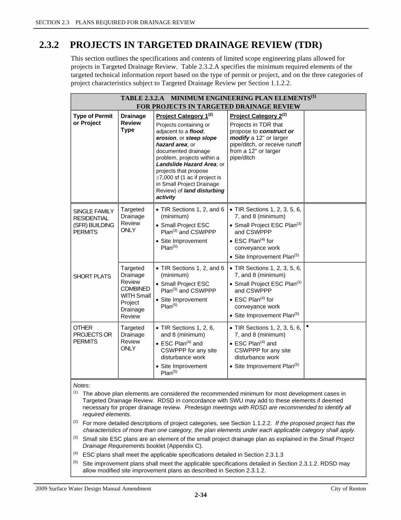
SECTION 2.3 PLANS REQUIRED FOR DRAINAGE REVIEW
2009 Surface Water Design Manual Amendment City of Renton
2-34
2.3.2 PROJECTS IN TARGETED DRAINAGE REVIEW (TDR) This section outlines the specifications and contents of limited scope engineering plans allowed for projects in Targeted Drainage Review. Table 2.3.2.A specifies the minimum required elements of the targeted technical information report based on the type of permit or project, and on the three categories of project characteristics subject to Targeted Drainage Review per Section 1.1.2.2.
TABLE 2.3.2.A MINIMUM ENGINEERING PLAN ELEMENTS(1) FOR PROJECTS IN TARGETED DRAINAGE REVIEW
Type of Permit or Project
Drainage Review Type
Project Category 1(2) Projects containing or adjacent to a flood, erosion, or steep slope hazard area; or documented drainage problem, projects within a Landslide Hazard Area; or projects that propose ≥7,000 sf (1 ac if project is in Small Project Drainage Review) of land disturbing activity
Project Category 2(2) Projects in TDR that propose to construct or modify a 12" or larger pipe/ditch, or receive runoff from a 12" or larger pipe/ditch
SINGLE FAMILY RESIDENTIAL (SFR) BUILDING PERMITS
SHORT PLATS
Targeted Drainage Review ONLY
• TIR Sections 1, 2, and 6 (minimum)
• Small Project ESC Plan(3) and CSWPPP
• Site Improvement Plan(5),
• TIR Sections 1, 2, 3, 5, 6, 7, and 8 (minimum)
• Small Project ESC Plan(3) and CSWPPP
• ESC Plan(4) for conveyance work
• Site Improvement Plan(5)
Targeted Drainage Review COMBINED WITH Small Project Drainage Review
• TIR Sections 1, 2, and 6 (minimum)
• Small Project ESC Plan(3) and CSWPPP
• Site Improvement Plan(5)
• TIR Sections 1, 2, 3, 5, 6, 7, and 8 (minimum)
• Small Project ESC Plan(3) and CSWPPP
• ESC Plan(4) for conveyance work
• Site Improvement Plan(5)
OTHER PROJECTS OR PERMITS
Targeted Drainage Review ONLY
• TIR Sections 1, 2, 6, and 8 (minimum)
• ESC Plan(4) and CSWPPP for any site disturbance work
• Site Improvement Plan(5)
• TIR Sections 1, 2, 3, 5, 6, 7, and 8 (minimum)
• ESC Plan(4) and CSWPPP for any site disturbance work
• Site Improvement Plan(5)
•
Notes: (1) The above plan elements are considered the recommended minimum for most development cases in
Targeted Drainage Review. RDSD in concordance with SWU may add to these elements if deemed necessary for proper drainage review. Predesign meetings with RDSD are recommended to identify all required elements.
(2) For more detailed descriptions of project categories, see Section 1.1.2.2. If the proposed project has the characteristics of more than one category, the plan elements under each applicable category shall apply.
(3) Small site ESC plans are an element of the small project drainage plan as explained in the Small Project Drainage Requirements booklet (Appendix C).
(4) ESC plans shall meet the applicable specifications detailed in Section 2.3.1.3 (5) Site improvement plans shall meet the applicable specifications detailed in Section 2.3.1.2. RDSD may
allow modified site improvement plans as described in Section 2.3.1.2.
2.4.1 PLAN CHANGES AFTER DRAINAGE REVIEW APPROVAL
2009 Surface Water Design Manual Amendment City of Renton
2-35
2.4 PLANS REQUIRED AFTER DRAINAGE REVIEW This section includes the specifications and contents required of those plans submitted at the end of the permit review process or after a permit has been issued.
2.4.1 PLAN CHANGES AFTER DRAINAGE REVIEW APPROVAL If changes or revisions to the originally approved engineering plans require additional review, the revised plans shall be submitted to RDSD for approval prior to construction depending on level of change. The plan change submittals shall include all of the following:
1. One copy of the revised TIR or addendum
2. Three sets of the engineering plans
3. Other information needed for review.
2.4.2 FINAL AS BUILT CORRECTED DRAWING SUBMITTAL During the course of construction, changes to the approved engineering plans are often required to address unforeseen field conditions or design improvements. Once construction is completed, it is the applicant's responsibility to submit to RDSD an as built drawing. These corrected drawings must be professionally drafted revisions applied to the original approved plan, excluding the CSWPP plan, and must include all changes made during the course of construction. The final corrected plan must be stamped, signed, and dated by a civil engineer. A CAD drawing file (.dwg) of the as built drawing applied with all original design information must be submitted along with paper copies and mylars. The CAD file must contain all the pages of the plan set for road and drainage infrastructure, but need not contain other sheets. Specific requirements for as builts are specified in the survey standards.
Disposition of Approved Engineering Plans for Subdivisions RDSD will retain a reproducible set (mylar media), utilizing it for public inspection, distribution, and base reference as required.

2009 Surface Water Design Manual Amendment City of Renton
CHAPTER 3 HYDROLOGIC ANALYSIS AND DESIGN
CITY OF RENTON AMENDMENTS TO THE KING COUNTY SURFACE WATER DESIGN MANUAL February 2010

2009 Surface Water Design Manual Amendment City of Renton
3-1
CHAPTER 3 HYDROLOGIC ANALYSIS AND DESIGN
The City of Renton has made the following changes to Chapter 3 of the 2009 KCSWDM. Users should refer to the County document for guidance on hydrologic analysis and design.
3.1.2 FLOW CONTROL STANDARDS • This section (starting on p. 3-5) is deleted. Refer to Chapter 1, Section 1.2.3, for flow control
standards.
3.2 RUNOFF COMPUTATION AND ANALYSIS METHODS • Add the following bullet in the first paragraph:
• The use of the Western Washington Hydrologic Model (WWHM) is allowed only for sizing rain gardens for basic and enhanced water quality treatment per Section 6.7.1.
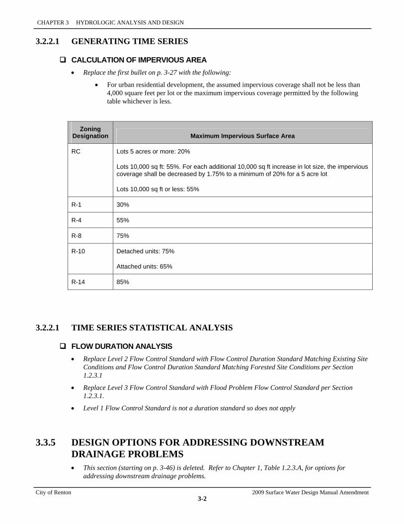
CHAPTER 3 HYDROLOGIC ANALYSIS AND DESIGN
City of Renton 2009 Surface Water Design Manual Amendment
3-2
3.2.2.1 GENERATING TIME SERIES
CALCULATION OF IMPERVIOUS AREA • Replace the first bullet on p. 3-27 with the following:
• For urban residential development, the assumed impervious coverage shall not be less than 4,000 square feet per lot or the maximum impervious coverage permitted by the following table whichever is less.
Zoning Designation Maximum Impervious Surface Area
RC Lots 5 acres or more: 20%
Lots 10,000 sq ft: 55%. For each additional 10,000 sq ft increase in lot size, the impervious coverage shall be decreased by 1.75% to a minimum of 20% for a 5 acre lot
Lots 10,000 sq ft or less: 55%
R-1 30%
R-4 55%
R-8 75%
R-10 Detached units: 75%
Attached units: 65%
R-14 85%
3.2.2.1 TIME SERIES STATISTICAL ANALYSIS
FLOW DURATION ANALYSIS • Replace Level 2 Flow Control Standard with Flow Control Duration Standard Matching Existing Site
Conditions and Flow Control Duration Standard Matching Forested Site Conditions per Section 1.2.3.1
• Replace Level 3 Flow Control Standard with Flood Problem Flow Control Standard per Section 1.2.3.1.
• Level 1 Flow Control Standard is not a duration standard so does not apply
3.3.5 DESIGN OPTIONS FOR ADDRESSING DOWNSTREAM DRAINAGE PROBLEMS • This section (starting on p. 3-46) is deleted. Refer to Chapter 1, Table 1.2.3.A, for options for
addressing downstream drainage problems.
2009 Surface Water Design Manual Amendment City of Renton
CHAPTER 4 CONVEYANCE SYSTEM ANALYSIS AND DESIGN
CITY OF RENTON AMENDMENTS TO THE KING COUNTY SURFACE WATER DESIGN MANUAL February 2010

2009 Surface Water Design Manual Amendment City of Renton
4-1
CHAPTER 4 CONVEYANCE SYSTEM ANALYSIS AND DESIGN
The City of Renton has made the following changes to Chapter 4 of the 2009 King County Manual. Users should refer to the County document for guidance on hydraulic analysis and design.
Note: As stated in the Introduction, all references to the King County Roads Standard shall be replaced with the City of Renton Standard Details and the requirements of the City of Renton Transportation Department and Surface Water Utility as applicable.
4.1.2 EASEMENT AND SETBACK REQUIREMENTS • Replace paragraph #1 with the following (p. 4-3):
1. Any onsite conveyance system element constructed as part of subdivision project shall be located in a dedicated drainage easement, tract, or right-of-way that preserves the system's route and conveyance capacity as follows:
• Onsite conveyance systems within the right-of-way will be inspected and maintained by the City.
• Onsite conveyance systems within the drainage easements or tracts will be maintained by the property owners through the Homeowners Association created by the subdivision (with each property owner having equal responsibility for maintenance). These conveyance elements include those entering and exiting the tract from/to the public right-of-way. For conveyance pipes entering the tract from right-of-way, responsibility begins at the last structure prior to entering the tract. For conveyance pipes exiting the tract to right-of-way, responsibility ends at the next downstream structure. The easement shall grant the City rights for inspection.
Exception: Roof downspout, minor yard, and footing drains do not require easements, tracts, or right-of-way. If easements are provided for these minor drains (or for other utilities such as power, gas, or telephone), they need not comply with the requirements of this section.
• Replace the first sentence in paragraph #3 with the following (p. 4-3):
Any offsite conveyance system element constructed through private property as part of a proposed project that conveys runoff from public roads within the project site shall be located in a drainage easement dedicated to the City.
SECTION 4 CONVEYANCE SYSTEM ANALYSIS AND DESIGN
City of Renton 2009 Surface Water Design Manual Amendment
4-2
• Replace the first sentence in paragraph # 4 with the following (p. 4-4):
A river protection easement per Reference Section 8-P (or equivalent) shall be required for all properties adjoining or including major rivers1 that may be dedicated to the City or County as applicable. The County shall review and approve river protection easements dedicated to the County.
4.2.1.1 DESIGN CRITERIA
General • Insert the following paragraph prior to the first paragraph under the “General” heading (p. 4-7):
In addition to the design criteria described below, pipe systems shall be design to meet the hydraulic criteria as described in Section 1.2.4.1. These criteria supersede the methodology descriptions contained in Chapter 4.
Acceptable Pipe Sizes • Replace the first paragraph with the following (p. 4-7):
Acceptable pipe sizes shall be per Table 4.2.1.A2.
Allowable Pipe Materials • Insert the following paragraph and Table 4.2.1.A1 for allowable pipe materials and minimum cover
requirements (p. 4-7):
The designer shall have the option of constructing storm sewers, drains and culverts of the pipe types listed below within the cover limits specified. In addition, concrete pipe shall be rubber gasketed and metal pipe shall be gasketed and securely banded. Leak testing shall be conducted if required by the City Engineer.
• Delete Footnote 5. PVC is not permitted in public right-of-way.
1 Major rivers are defined in the King County Flood Hazard Reduction Plan.
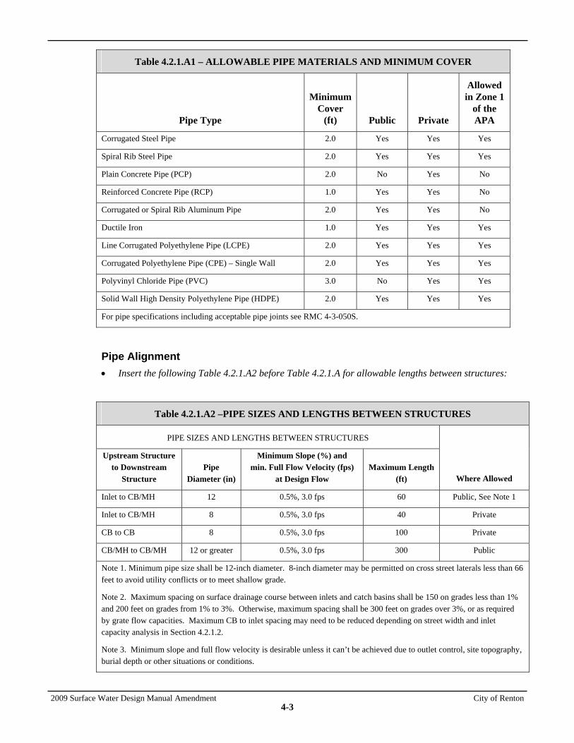
2009 Surface Water Design Manual Amendment City of Renton
4-3
Table 4.2.1.A1 – ALLOWABLE PIPE MATERIALS AND MINIMUM COVER
Pipe Type
Minimum Cover
(ft) Public Private
Allowed in Zone 1
of the APA
Corrugated Steel Pipe 2.0 Yes Yes Yes
Spiral Rib Steel Pipe 2.0 Yes Yes Yes
Plain Concrete Pipe (PCP) 2.0 No Yes No
Reinforced Concrete Pipe (RCP) 1.0 Yes Yes No
Corrugated or Spiral Rib Aluminum Pipe 2.0 Yes Yes No
Ductile Iron 1.0 Yes Yes Yes
Line Corrugated Polyethylene Pipe (LCPE) 2.0 Yes Yes Yes
Corrugated Polyethylene Pipe (CPE) – Single Wall 2.0 Yes Yes Yes
Polyvinyl Chloride Pipe (PVC) 3.0 No Yes Yes
Solid Wall High Density Polyethylene Pipe (HDPE) 2.0 Yes Yes Yes
For pipe specifications including acceptable pipe joints see RMC 4-3-050S.
Pipe Alignment • Insert the following Table 4.2.1.A2 before Table 4.2.1.A for allowable lengths between structures:
Table 4.2.1.A2 –PIPE SIZES AND LENGTHS BETWEEN STRUCTURES
PIPE SIZES AND LENGTHS BETWEEN STRUCTURES
Upstream Structure to Downstream
Structure Pipe
Diameter (in)
Minimum Slope (%) and min. Full Flow Velocity (fps)
at Design Flow Maximum Length
(ft) Where Allowed
Inlet to CB/MH 12 0.5%, 3.0 fps 60 Public, See Note 1
Inlet to CB/MH 8 0.5%, 3.0 fps 40 Private
CB to CB 8 0.5%, 3.0 fps 100 Private
CB/MH to CB/MH 12 or greater 0.5%, 3.0 fps 300 Public
Note 1. Minimum pipe size shall be 12-inch diameter. 8-inch diameter may be permitted on cross street laterals less than 66 feet to avoid utility conflicts or to meet shallow grade.
Note 2. Maximum spacing on surface drainage course between inlets and catch basins shall be 150 on grades less than 1% and 200 feet on grades from 1% to 3%. Otherwise, maximum spacing shall be 300 feet on grades over 3%, or as required by grate flow capacities. Maximum CB to inlet spacing may need to be reduced depending on street width and inlet capacity analysis in Section 4.2.1.2.
Note 3. Minimum slope and full flow velocity is desirable unless it can’t be achieved due to outlet control, site topography, burial depth or other situations or conditions.
SECTION 4 CONVEYANCE SYSTEM ANALYSIS AND DESIGN
City of Renton 2009 Surface Water Design Manual Amendment
4-4
Changes in Pipe Size • Replace paragraph #1 with the following (p. 4-9):
1. Increases or decrease in pipe size are allowed only at structures. Exceptions may be allowed as follows:
Connections to pipe systems may be made without placing a catch basin or manhole on the mainline by meeting all of the following conditions:
a. The mainline pipe is 48inches or greater and at least two times the size of the connecting pipe.
b. Make connections in accordance with the manufacture’s recommendations. Standard shop fabricated tees, wyes and saddles shall be used, except for concrete connections constructed in accordance with Figure 7-002 in Appendix E. (This is a King County detail adopted by the City of Renton by reference.)
c. There shall be a catch basin or manhole on the connecting pipe within 2 to 10 feet of the external wall of the main line.
d. Offset angle of connecting pipe to mainline, horizontally and vertically shall be less than 45 degrees.
e. Two-point survey control shall be used to set catch basin locations.
Structures • Add requirements 6 through 20 to requirements 1 through 5 (p. 4-10):
6. Catch basins (see City of Renton Std Details) rather than inlets shall be used to collect storm water from road surfaces, unless approved by the City Engineer.
7. Type 2 (see City of Renton Std Detail) catch basins shall be used where the depth to the invert of the pipe exceeds 5 feet.
8. Manholes (see City of Renton Std Details) may be used in lieu of catch basins if they do not collect surface water. Manholes must be used if inverts are greater than 18 feet.
9. Roof and yard drains, or other concentrated flow from adjacent property shall not discharge over the surface of roadways, sidewalks, walkways, or shoulders.
10. Catch basins or manholes are required when joining differing types of pipes.
11. The location of at least two points of all catch basins shall be surveyed to ensure that the catch basin, frame and grate will properly align with finished curb, horizontally and vertically.
12. Metal castings for drainage structures shall not be dipped, painted, welded, plugged or repaired.
13. Porosity in metal castings for drainage structures shall be considered a workmanship defect subject to rejection by the inspector.
14. Grates and covers shall be seated properly to prevent rocking, including the replacement of existing covers with solid metal covers.
15. Unless otherwise specified, vaned grates (see City Std. detail), shall be used with standard frame in the traveled way, gutter, or shoulder. Vaned grates shall not be located within crosswalks.
16. At sag vertical curves, on the end of downgrade cul-de-sacs, or before intersections with a grade four percent or greater, an analysis shall be done to assure that typical catch basin grates will collect the surface runoff. To collect excessive volumes of runoff or protect against plugged grates and overflow situations, the City Road Engineer will require the use of through inlet frames on vertical curbs, (see City of Renton Std. detail). Where the through-curb inlets cannot be used, place a catch basin at the
2009 Surface Water Design Manual Amendment City of Renton
4-5
low point and two extra inlets located not greater than 0.1 foot above the low point grate within a spacing of 25 feet.
17. New catch basins and manholes that do not collect runoff shall use solid locking covers (per City of Renton Standard details). Existing catch basins, which no longer collect runoff, shall have their frame and grates replaced with solid covers..
18. All storm drain covers and grates need to be locking regardless of their location.
19. Slit drains may be used when approved by the City Engineer. At a minimum slit drains shall have catch basins at either end unless used as a driveway culvert. The maximum distance between catch basins along a slit drain shall be 50 feet.
• Replace Note 1 in Table 4.2.1.B with the following:
(1) Catch basins and manholes (including manhole steps, ladders, and handholes) shall conform to City of Renton Standard Details.
Pipe Cover • Replace the first sentence in paragraph #1 with the following (p. 4-11):
Pipe cover, measured from the finished grade elevation to the top of the outside surface of the pipe, shall be 2 feet minimum unless otherwise specified or allowed below or as allowed above in Table 4.2.1.A1, “Allowable Pipe Materials.”
• Replace the first sentence in paragraph #2 with the following (p. 4-11):
All flexible storm sewer pipe and culvert material shall be covered by a minimum of 2 feet of cover unless the applicant submits detailed plans accompanied by manufacturer’s recommendations specifying allowable cover less than 2 feet in depth. All non-flexible storm sewer pipe and culvert material shall be covered by a minimum of 1 foot of cover.
• Add the following note to Table 4.2.1.C (p. 4-11):
Note: Only Class IV and V are allowed in public right-of-way.
Pipe Clearances • Replace in entirety with the following (p. 4-11):
A minimum 7-foot horizontal separation and 1-foot vertical separation (measured wall to wall) is required between storm pipe and other utilities with the exception of water lines where a minimum 10-foot horizontal separation is required.
Pipe Compaction and Backfill • Replace reference to Figure 4.2.1A (p. 4-11) with City of Renton Standard Plan B063 – Pipe
Compaction Designs and Backfill.

SECTION 4 CONVEYANCE SYSTEM ANALYSIS AND DESIGN
City of Renton 2009 Surface Water Design Manual Amendment
4-6
Pipe System Connections • Replace the third sentence with the following (p. 4-12):
Additional exceptions may be made provided the following conditions are met:
1. The mainline pipe is 48 inches or greater and at least two times the size of the connecting pipe.
2. Make connections in accordance with the manufacturer’s recommendations. Standard shop fabricated tees, wyes and saddles shall be used, except for concrete connections constructed in accordance with Figure 7-002 in Appendix E. (This is a King County detail adopted by the City of Renton by reference.)
3. There shall be a catch basin or manhole on the connecting pipe within 2 to 10 feet of the external wall of the main line.
4. Offset angle of connecting pipe to mainline, horizontally and vertically shall be less than 45 degrees.
• Add the following paragraph after the first paragraph:
Storm drainage pipe systems shall not penetrate building foundations, except for sump pump discharge lines used to drain crawl spaces, provided the sump pump system includes a backflow prevention or a check valve.
Spill Control • Delete paragraph b (p. 4-12). Elbows are not allowed for spill control.
Debris Barriers • Add the following sentence after the first sentence (p. 4-12):
Debris barriers for pipes smaller than 18 inches and larger than 36 inches in diameter may be required depending on conditions and safety concerns.
Other Details • Delete and replace this paragraph with the following (p. 4-13):
In addition to the details shown in Figure 4.2.1.A (p. 4-14) through Figure 4.2.1.E (p. 4-18), the City of Renton Standard Details in Appendix E and APWA/WSDOT Standard Plans for Road, Bridge and Municipal Construction. Commonly used details include field tapping of concrete pipe, catch basins and catch basin details, manholes and manhole details, curb inlets, frames, grates, and covers.
4.2.1.2 METHODS OF ANALYSIS
Uniform Flow Analysis Method • Insert the following paragraph before the first paragraph (p. 4-19):
In addition to the design criteria described below, new pipe systems shall be design to meet the hydraulic criteria as described in Section 1.2.4.1.
2009 Surface Water Design Manual Amendment City of Renton
4-7
4.2.3.1 DESIGN CRITERIA • Add minimum requirements 6 and 7 to minimum requirements 1 through 5 (p. 4-36):
6. The pump system shall have either installed emergency backup power or the ability for portable backup power generator in the event of a loss of primary power. If portable backup emergency power is provided, the appliance must include a description of how the backup power will be brought to the site during an emergency within an emergency response plan (discussed below).
7. The applicant must provide an emergency response plan which details how backup power will be activated during an emergency and include method for delivering to the site and energizing portable backup power. The emergency response plan must also describe response for pump failures including repair and replacement of damaged pumps/motors and generators.
4.3.1.1 DESIGN CRITERIA
General • Insert the following paragraph before the first paragraph under the “General” heading (p. 4-37):
In addition to the design criteria described below, culverts shall be design to meet the hydraulic criteria as described in Section 1.2.4.1.
• Delete the second sentence in paragraph #2.
Inlets and Outlets • Add the following sentence after the first sentence in paragraph #4:
Debris barriers for pipes smaller than 18 inches and larger than 36 inches in diameter may be required depending on conditions and safety concerns.
4.3.3 BRIDGES • Replace the third sentence with the following (p. 4-53):
In addition to the design criteria for conveyance described below, bridge designs must meet the City of Renton Transportation requirements, AASHTO Standard Specifications for Highway Bridges or AASHTO LRFD Bridge Design Specifications and the most current WSDOT/APWA Standard Specifications as well as other agencies such as the Washington State Department of Fish and Wildlife (WDFW).
4.3.3.1 DESIGN CRITERIA • Add the following to the third paragraph (p. 4-53):
For stream crossing locations where the 100-year peak flow exceeds 100 cfs, the height of a bridge clearance above rivers and streams shall be a minimum three feet above the 100-year water surface elevation unless otherwise required by the City based on evaluation of the design criteria in this section. For stream crossing locations where the 100-year peak flow is 100 cfs or less, there is no specific clearance requirement.
SECTION 4 CONVEYANCE SYSTEM ANALYSIS AND DESIGN
City of Renton 2009 Surface Water Design Manual Amendment
4-8
Bed Aggradation • Replace the last sentence of the second paragraph with the following (p. 4-53):
The location and design of bridges and approach roads shall consider channel migration hazards.
4.4.2.2 APPROXIMATE FLOODPLAIN STUDY • In paragraph #2 (p. 4-72), remove reference to KCC 21A.24.
4.4.2.3 APPROXIMATE FLOODPLAIN STUDY • In paragraph 2 (p. 4-72), remove reference to KCC 21A.24 (and associated rule).
4.4.2.4 MAJOR FLOODPLAIN/FLOODWAY STUDY
DETERMINING FLOOD FLOWS • Insert the following sentence before the first paragraph (p. 4-74):
The floodplain analysis shall be based on the 100-year storm event using existing land use hydrology except as noted in the paragraph titled “Flood Flows from Adopted Basin Plan Information.”
2009 Surface Water Design Manual Amendment City of Renton
CHAPTER 5 FLOW CONTROL DESIGN
CITY OF RENTON AMENDMENTS TO THE KING COUNTY SURFACE WATER DESIGN MANUAL February 2010

2009 Surface Water Design Manual Amendment City of Renton
5-1
CHAPTER 5 FLOW CONTROL DESIGN
The City of Renton has made the following changes to Chapter 5 of the 2009 KCSWDM. Users should refer to the County document for guidance on flow control design.
Standards details provided in this chapter are not applicable in the City of Renton. See appendix E, City of Renton Standard Details of the Surface Water Design Manual for reference. The figures provided in Appendix E illustrate one example of how the Flow Control facility design criteria may be applied. Although the figures are meant to illustrate many of the most important design criteria, they may not show all criteria that apply. In general, the figures in Appendix E are not used to specify requirements unless they are indicated elsewhere in the Manual. If the King County Surface Water Design Manual refers to a detail not provided by the City of Renton, the applicant shall use the Standard Detail provided in the Manual.
Note: As stated in the Introduction, all references to the King County Roads Standard shall be replaced with the City of Renton Standard Details and the requirements of the City of Renton Transportation Department and Surface Water Utility as applicable.
Maintenance and Operation For residential plats, commercial and industrial sites, maintenance and operation of flow control facilities is the responsibility of the property owner(s) and must be located in a tract or dedicated easement that identifies each property owner as having equal and undivided interest per Section 1.2.6.
5.2.2.2 USE OF CREDITS BY PROJECTS WITHIN RIGHTS-OF-WAY • Replace paragraph #2 with the following (p.5-16):
The BMP must be approved through an adjustment / variance process in accordance with Section 1.4
5.3.1.1 DESIGN CRITERIA (DETENTION PONDS) Detention Ponds in Recreational Tracts • Remove in entirety (p. 5-25).
Detention Ponds in Open Space • Remove in entirety (p. 5-25).
SECTION 5 FLOW CONTROL DESIGN
City of Renton 2009 Surface Water Design Manual Amendment
5-2
5.3.3.1 DESIGN CRITERIA (DETENTION VAULTS)
FIGURE 5.3.1.D PERMANENT SURFACE WATER CONTROL POND SIGN
• Replace King County references and logo with those of City of Renton. Replace DNR phone number with that of City of Renton (p. 5-29).
5.4.1 GENERAL REQUIREMENTS FOR INFILTRATION FACILITIES • Add the following sentence to the end of the first paragraph (p. 5-57):
Infiltration facilities are prohibited in zone 1 of the Aquifer Protection Area.
GROUNDWATER PROTECTION • Replace first paragraph with the following (p. 5-62):
The protection of groundwater quality is recognized as an issue of greater concern that in the past, and groundwater protection standards are changing rapidly, see section 1.3.6 Core requirement #6: Aquifer Protection Area. Increased safeguards are often required. The applicant should refer to Reference 11, Ground Water Protection Area Map of the Surface Water Design Manual, to determine if the project lies within a groundwater protection area.
• Delete note.
2009 Surface Water Design Manual Amendment City of Renton
CHAPTER 6 WATER QUALITY DESIGN
CITY OF RENTON AMENDMENT TO THE 2009 KING COUNTY, WASHINGTON SURFACE WATER DESIGN MANUAL February 2010

2009 Surface Water Design Manual Amendment City of Renton
6-1
CHAPTER 6 WATER QUALITY DESIGN
The City of Renton has made minor changes to Chapter 6 of the 2009 KCSWDM. Users should refer to the County document for guidance on water quality design, except for Rain Gardens. Design criteria for Rain Gardens is specified in this Amendment document
Note: As stated in the Introduction, all references to the King County Roads Standard shall be replaced with the City of Renton Standard Details and the requirements of the City of Renton Transportation Department and Surface Water Utility as applicable.
Required vs. Recommended Design Criteria Use of Chapter 6 Figures:
• Delete entirely and replace with the following (p. 6-1)
Standards details provided in chapter 6 are not applicable in the City of Renton. See appendix E, City of Renton Standard Details of the Surface Water Design Manual for reference. The figures provided in Appendix E illustrate one example of how the WQ facility design criteria may be applied. Although the figures are meant to illustrate many of the most important design criteria, they may not show all criteria that apply. In general, the figures in Appendix E are not used to specify requirements unless they are indicated elsewhere in the Manual. If the King County Surface Water Design Manual refers to a detailed not provided by the City of Renton, the applicant shall use the Standard Detail provided in the manual.
6.1 WATER QUALITY MENUS • Delete reference to Sensitive Lake Protection Menu and Sphagnum Bog Protection Menu (p. 6-3)
• Replace “Guide To Applying Water Quality Menus” with the following (p. 6-3):
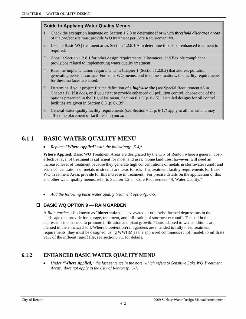
CHAPTER 6 WATER QUALITY DESIGN
City of Renton 2009 Surface Water Design Manual Amendment
6-2
Guide to Applying Water Quality Menus 1. Check the exemption language on Section 1.2.8 to determine if or which threshold discharge areas
of the project site must provide WQ treatment per Core Requirement #8.
2. Use the Basic WQ treatment areas Section 1.2.8.1.A to determine if basic or enhanced treatment is required.
3. Consult Section 1.2.8.1 for other design requirements, allowances, and flexible compliance provisions related to implementing water quality treatment.
4. Read the implementation requirements in Chapter 1 (Section 1.2.8.2) that address pollution generating pervious surface. For some WQ menus, and in dome situations, the facility requirements for these surfaces are eased.
5. Determine if your project fits the definition of a high-use site (see Special Requirement #5 in Chapter 1). If it does, or if you elect to provide enhanced oil pollution control, choose one of the options presented in the High-Use menu, Section 6.1.5 (p. 6-15). Detailed designs for oil control facilities are given in Section 6.6 (p. 6-139).
6. General water quality facility requirements (see Section 6.2, p. 6-17) apply to all menus and may affect the placement of facilities on your site.
6.1.1 BASIC WATER QUALITY MENU • Replace “Where Applied” with the following(p. 6-4):
Where Applied: Basic WQ Treatment Areas are designated by the City of Renton where a general, cost-effective level of treatment is sufficient for most land uses. Some land uses, however, will need an increased level of treatment because they generate high concentrations of metals in stormwater runoff and acute concentrations of metals in streams are toxic to fish. The treatment facility requirements for Basic WQ Treatment Areas provide for this increase in treatment. For precise details on the application of this and other water quality menus, refer to Section 1.2.8, "Core Requirement #8: Water Quality."
• Add the following basic water quality treatment option(p. 6-5):
BASIC WQ OPTION 9 ⎯ RAIN GARDEN A Rain garden, also known as "bioretention," is excavated or otherwise formed depressions in the landscape that provide for storage, treatment, and infiltration of stormwater runoff. The soil in the depression is enhanced to promote infiltration and plant growth. Plants adapted to wet conditions are planted in the enhanced soil. Where bioretention/rain gardens are intended to fully meet treatment requirements, they must be designed, using WWHM as the approved continuous runoff model, to infiltrate 91% of the influent runoff file; see section6.7.1 for details.
6.1.2 ENHANCED BASIC WATER QUALITY MENU • Under “Where Applied,” the last sentence in the note, which refers to Sensitive Lake WQ Treatment
Areas, does not apply in the City of Renton (p. 6-7).

2009 Surface Water Design Manual Amendment City of Renton
6-3
• Add the following enhanced basic water quality treatment option (p. 6-7):
ENHANCED BASIC WQ OPTION 4 ⎯ RAIN GARDEN A Rain garden, also known as "bioretention," is excavated or otherwise formed depressions in the landscape that provide for storage, treatment, and infiltration of stormwater runoff. The soil in the depression is enhanced to promote infiltration and plant growth. Plants adapted to wet conditions are planted in the enhanced soil. Where bioretention/rain gardens are intended to fully meet treatment requirements, they must be designed, using WWHM as the approved continuous runoff model, to infiltrate 91% of the influent runoff file. Figure C.2.5.A (p. C-61) shows a plan view and section of a typical rain garden system.
6.1.3 SENSITIVE LAKE PROTECTION MENU • Delete section entirely (p. 6-9 through 6-12).
6.1.4 SPHAGNUM BOG PROTECTION MENU • Delete section entirely (p. 6-9 through 6-12).
6.2 GENERAL REQUIREMENTS FOR WQ FACILITIES
Emerging Technologies • Replace paragraph with the following (p. 6-17):
Only treatment facilities that have been given a general use level designation through the state Department of Ecology’s Technology Assessment Protocol – Ecology (TAPE) program will be consider for approval by the City of Renton through an adjustment process for water quality treatment. A list of approved water treatment technologies can be found on the Department of Ecology website at http://www.ecy.wa.gov/programs/wq/stormwater/newtech/index.html
• Add the following requirement (p. 6-17):
Groundwater Protection Open Water quality facilities including wetponds, biofiltration swales, bioretention facilities, infiltration facilities and stormwater wetlands are prohibited in Zone 1 of the Aquifer Protection Area.
6.2.1 WATER QUALITY DESIGN FLOWS
Water Quality Design Flow • Replace first paragraph with the following (p. 6-17):
The water quality design flow is defined as follows except for Rain Gardens were the water quality design flow shall comply with the criteria described in Section 6.7.1 .
• Add the following bullet (p. 6-17)
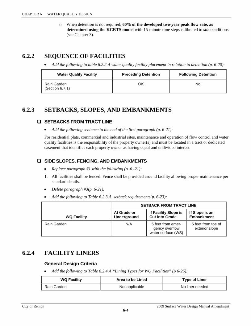
CHAPTER 6 WATER QUALITY DESIGN
City of Renton 2009 Surface Water Design Manual Amendment
6-4
o When detention is not required: 60% of the developed two-year peak flow rate, as determined using the KCRTS model with 15-minute time steps calibrated to site conditions (see Chapter 3).
6.2.2 SEQUENCE OF FACILITIES • Add the following to table 6.2.2.A water quality facility placement in relation to detention (p. 6-20):
Water Quality Facility Preceding Detention Following Detention
Rain Garden (Section 6.7.1)
OK No
6.2.3 SETBACKS, SLOPES, AND EMBANKMENTS
SETBACKS FROM TRACT LINE • Add the following sentence to the end of the first paragraph (p. 6-21):
For residential plats, commercial and industrial sites, maintenance and operation of flow control and water quality facilities is the responsibility of the property owner(s) and must be located in a tract or dedicated easement that identifies each property owner as having equal and undivided interest.
SIDE SLOPES, FENCING, AND EMBANKMENTS • Replace paragraph #1 with the following (p. 6.-21):
1. All facilities shall be fenced. Fence shall be provided around facility allowing proper maintenance per standard details.
• Delete paragraph #3(p. 6-21).
• Add the following to Table 6.2.3.A setback requirements(p. 6-23):
WQ Facility
SETBACK FROM TRACT LINE
At Grade or Underground
If Facility Slope is Cut into Grade
If Slope is an Embankment
Rain Garden N/A 5 feet from emer-gency overflow
water surface (WS)
5 feet from toe of exterior slope
6.2.4 FACILITY LINERS
General Design Criteria • Add the following to Table 6.2.4.A “Lining Types for WQ Facilities” (p 6-25):
WQ Facility Area to be Lined Type of Liner
Rain Garden Not applicable No liner needed

2009 Surface Water Design Manual Amendment City of Renton
6-5
6.2.5.2 DESIGN CRITERIA
General • In paragraph #7, replace reference to King County Road Standards to City of Renton Standard
Details (p. 6-29).
6.4.1.2 DESIGN CRITERIA
Recommended Design Features • Delete paragraph #8 (p. 6-78).
FIGURE 6.4.1.C WATERFOWL SIGN (p. 6-82)
• Replace King County logo on sign with City of Renton logo.
6.6.1.2 DESIGN CRITERIA
General • In paragraph #4, replace reference to King County Road Standards with City of Renton Standard
Details (p. 6-142).
New Section (include after p. 6-156)
6.7 BIORETENTION FACILITY DESIGNS This section presents the methods, details of analysis, and design criteria for rain gardens. Included in this section are the following specific facility designs:
• “Rain Gardens”
6.7.1 RAIN GARDENS A rain garden, also known as "bioretention," is excavated or otherwise formed depressions in the landscape that provide for storage, treatment, and infiltration of stormwater runoff. The soil in the depression is enhanced to promote infiltration and plant growth. Plants adapted to wet conditions are planted in the enhanced soil.
Water Quality Design Storm Volume The volume of runoff predicted from a 24-hour storm with a 6-month return frequency (a.k.a., 6-month, 24-hour storm). Alternatively, the 91st percentile, 24-hour runoff volume indicated using the WWHM model.
Unless amended to reflect local precipitation statistics, the 6-month, 24- hour precipitation amount may be assumed to be 72 percent of the 2-year, 24-hour amount. Precipitation estimates of the 6-month and 2-year, 24- hour storms are provided in Figure 3.2.1.A 2 Year 24-Hour Isopluvials.
CHAPTER 6 WATER QUALITY DESIGN
City of Renton 2009 Surface Water Design Manual Amendment
6-6
Water Quality Design Flow Rate
Preceding Detention Facilities or when Detention Facilities are not required: The flow rate at or below which 91% of the runoff volume, as estimated by the WWHM model.
6.7.1.1 DESIGN CRITERIA
Soils 1. The soils surrounding bioretention facilities are a principle design element for determining infiltration
capacity, sizing and rain garden type. The planting soil mix placed in the cell or swale is a highly permeable soil mixed thoroughly with compost amendment, and a surface mulch layer.
2. Soil depth should be a minimum of 18 inches to provide acceptable minimum pollutant attenuation and good growing conditions for selected plants.
3. The texture for the soil component of the bioretention soil mix should be a loamy sand (USDA Soil Textural Classification). Clay content for the final soil mix should be less than 5 percent. The final soil mix (including compost and soil) should have a minimum short-term hydraulic conductivity of 1.0 inches/hour per ASTM Designation D 2434 (Standard Test Method for Permeability of Granular Soils) at 80 percent compaction per ASTM Designation D 1557.
4. The final soil mixture should have a minimum organic content of approximately 10 percent by dry weight.
5. The pH for the soil mix should be between 5.5 and 7.0.
Mulch layer 1. Bioretention areas can be designed with or without a mulch layer.
Compost 1. Material must be in compliance with WAC chapter 173-350-220. This code is available online at
http://www.ecy.wa.gov/programs/swfa/facilities/350.html. The pH must be between 5.5 and 7.0.
2. Carbon nitrogen ratio between 20:1 and 35:1 (35:1 CN ratio recommended for native plants)
3. Organic matter content should be between 35% and 65%.
Installation 1. Minimize compaction of the base and sidewalls of the bioretention area. Excavation should not be
allowed during wet or saturated conditions. Excavation should be performed by machinery operating adjacent to the bioretention facility and no heavy equipment with narrow tracks, narrow tires or large lugged, high pressure tires should be allowed on the bottom of the bioretention facility.
2. On-site soil mixing or placement should not be performed if soil is saturated. The bioretention soil mixture should be placed and graded by excavators and/or backhoes operating adjacent to the bioretention facility.
2009 Surface Water Design Manual Amendment City of Renton
6-7
Plant materials 1. Plants should be tolerant of ponding fluctuations and saturated soil conditions for the length of time
anticipated by the facility design, and drought during the summer months, for reference see table C.2.5.A Water tolerant Plants in Appendix C.
2. In general, the predominant plant material utilized in bioretention areas are facultative species adapted to stresses associated with wet and dry conditions.
Maximum ponding depth 1. A maximum ponding depth of 12 inches is recommended.
2. A maximum surface pool drawdown time of 24 hours is recommended.
3. Ponding depth and system drawdown should be specified so that soils dry out periodically in order to:
• Restore hydraulic capacity to receive flows from subsequent storms.
• Maintain infiltration rates.
• Maintain adequate soil oxygen levels for healthy soil biota and vegetation.
• Provide proper soil conditions for biodegradation and retention of pollutants.
6.7.1.2 LIMITATIONS 1. A minimum of 3 feet of clearance is necessary between the lowest elevation of the bioretention soil,
or any underlying gravel layer, and the seasonal high groundwater elevation or other impermeable layer if the area tributary to the rain garden meets or exceeds any of the following limitations:
• 5,000 square feet of pollution-generating impervious surface; or
• 10,000 square feet of impervious area; or
• ¾ acres of lawn and landscape.
2. If the tributary area to an individual rain garden does not exceed the areal limitations above, a minimum of 1 foot of clearance is adequate between the lowest elevation of the bioretention soil (or any underlying gravel layer) and the seasonal high groundwater elevation or other impermeable layer.
6.7.1.3 RUNOFF MODEL REPRESENTATION
Pothole design (bioretention cells) The rain garden is represented as a pond with a steady-state infiltration rate. Proper infiltration rate selection is described below. The pond volume is a combination of the above ground volume available for water storage and the volume available for storage within the imported soil. The above ground volume is the size of the “pothole” that accommodates standing water. A minimum ponding depth of 6-inches is recommended. The soil storage volume is determined by multiplying the volume occupied by the imported soil by the soil’s percent porosity. Use 40 percent porosity for bioretention planting mix soils recommended in section 6.7.1.1. That volume is presumed to be added directly below the surface soil profile of the rain garden. The theoretical pond dimensions are represented in the Pond Information/Design screen. The Effective Depth is the distance from the bottom of the theoretical pond to the height of the overflow. This depth is less than the actual depth because of the volume occupied by the soil. Approximate side slopes can be individually entered. On the Pond Information/Design screen, there is
CHAPTER 6 WATER QUALITY DESIGN
City of Renton 2009 Surface Water Design Manual Amendment
6-8
a button, which asks, “Use Wetted Surface Area?” Pushing that button is an affirmative response. Do not push the button if the rain garden has sidewalls steeper than 2 horizontal to 1 vertical.
Rain gardens with underlying perforated drain pipes that discharge to the surface can also be modeled as ponds with steady-state infiltration rates. However, the only volume available for storage (and modeled as storage as explained herein) is the void space within the imported material (usually sand or gravel) below the invert of the drain pipe.
Linear Design (bioretention swale or slopes) Where a swale design has a roadside slope and a back slope between which water can pond due to an elevated end, and an overflow/drainage pipe at the lower end of the swale, the swale may be modeled as a pond with a steady state infiltration rate. This method does not apply to swales that are underlain by a drainage pipe.
If the long-term infiltration rate through the imported bioretention soil is lower than the infiltration rate of the underlying soil, the surface dimensions and slopes of the swale should be entered into the WWHM as the pond dimensions and slopes. The effective depth is the distance from the soil surface at the bottom of the swale to the invert of the overflow/drainage pipe. If the infiltration rate through the underlying soil is lower than the estimated long-term infiltration rate through the imported bioretention soil, the pond dimensions entered into the WWHM should be adjusted to account for the storage volume in the void space of the bioretention soil. Use 40 percent porosity for bioretention planting mix soils recommended in section 6.7.1.1. For instance, if the soil is 40% voids, and the depth of the imported soils is 2 feet throughout the swale, the depth of the pond is increased by 0.8 feet. If the depth of imported soils varies within the side slopes of the swale, the theoretical side slopes of the pond can be adjusted.
This procedure to estimate storage space should only be used on bioretention swales with a 1% slope or less. Swales with higher slopes should more accurately compute the storage volume in the swale below the drainage pipe invert.
Slopes Where a bioretention design involves only a sloped surface such as the slope below the shoulder of an elevated road, the design can also be modeled as a pond with a steady state infiltration rate. This procedure only applies in instances where the infiltration rate through the underlying soil is less than the estimated long-term infiltration rate of the bioretention imported soil. In this case, the length of the bioretention slope should correspond to the maximum wetted cross-sectional area of the theoretical pond. The effective depth of the theoretical pond is the void depth of the bioretention soil as estimated by multiplying the measured porosity times the depth of the bioretention soils. Use 40 percent porosity for bioretention planting mix soils recommended in section 6.7.1.1.
6.7.1.4 INFILTRATION RATE DETERMINATIONS The assumed infiltration rate for the rain garden must be the lower of the estimated long-term rate of the imported soil or the initial (a.k.a. short-term or measured) infiltration rate of the underlying soil profile. Using one of the procedures explained below, the initial infiltration rates of the two soils must be determined. Then after applying an appropriate correction factor to the imported soil of the rain garden, the designer can compare and determine the lower of the long-term infiltration rate of the imported soil, and the initial infiltration rate of the underlying native soil. The underlying native soil does not need a correction factor because the overlying imported soil protects it. Below are explanations for how to determine infiltration rates for the imported and underlying soils, and how to use them with the WWHM.
6.7.1.5 IMPORTED SOILS FOR THE RAIN GARDEN 1. Method for imported soil in a rain garden with a tributary area of or exceeding any of the following
limitations: 5,000 square feet of pollution-generating impervious surface; or 10,000 square feet of impervious surface; or ¾ acres of lawn and landscape:
2009 Surface Water Design Manual Amendment City of Renton
6-9
a. Use ASTM D 2434 Standard Test Method for Permeability of granular Soils (Constant Head) with a compaction rate of 80% using ASTM D1557 Test Method for Laboratory Compaction Characteristics of Soil Using Modified Effort.
b. Use 4 as the infiltration reduction correction factor.
c. Compare this rate to the infiltration rate of the underlying soil (as determined using one of the methods below). If the long-term infiltration rate of the imported soil is lower, enter that infiltration rate and the correction factor into the corresponding boxes on the pond information/design screen of the WWHM.
2. Method for imported soil in a rain garden with a tributary area less than 5,000 square feet of pollution-generating impervious surface; and less than 10,000 square feet of impervious surface; and less than ¾ acres of lawn and landscape:
a. Use ASTM D 2434 Standard Test Method for Permeability of granular Soils (Constant Head) with a compaction rate of 80% using ASTM D1557 Test Method for Laboratory Compaction Characteristics of Soil Using Modified Effort.
b. Use 2 as the infiltration reduction correction factor.
c. Compare this rate to the infiltration rate of the underlying soil (as determined using one of the methods below). If the long-term infiltration rate of the imported soil is lower, enter that infiltration rate and the correction factor into the corresponding boxes on the pond information/design screen of the WWHM.
6.7.1.6 UNDERLYING SOIL
Method 1: Use Table 3.7 below to determine the short-term infiltration rate of the underlying soil. Soils not listed in the table cannot use this approach. Compare this short-term rate to the long-term rate determined above for the bioretention imported soil. If the short-term rate for the underlying soil is lower, enter it into the measured infiltration rate box on the pond information/design screen in the WWHM. Enter 1 as the infiltration reduction factor.
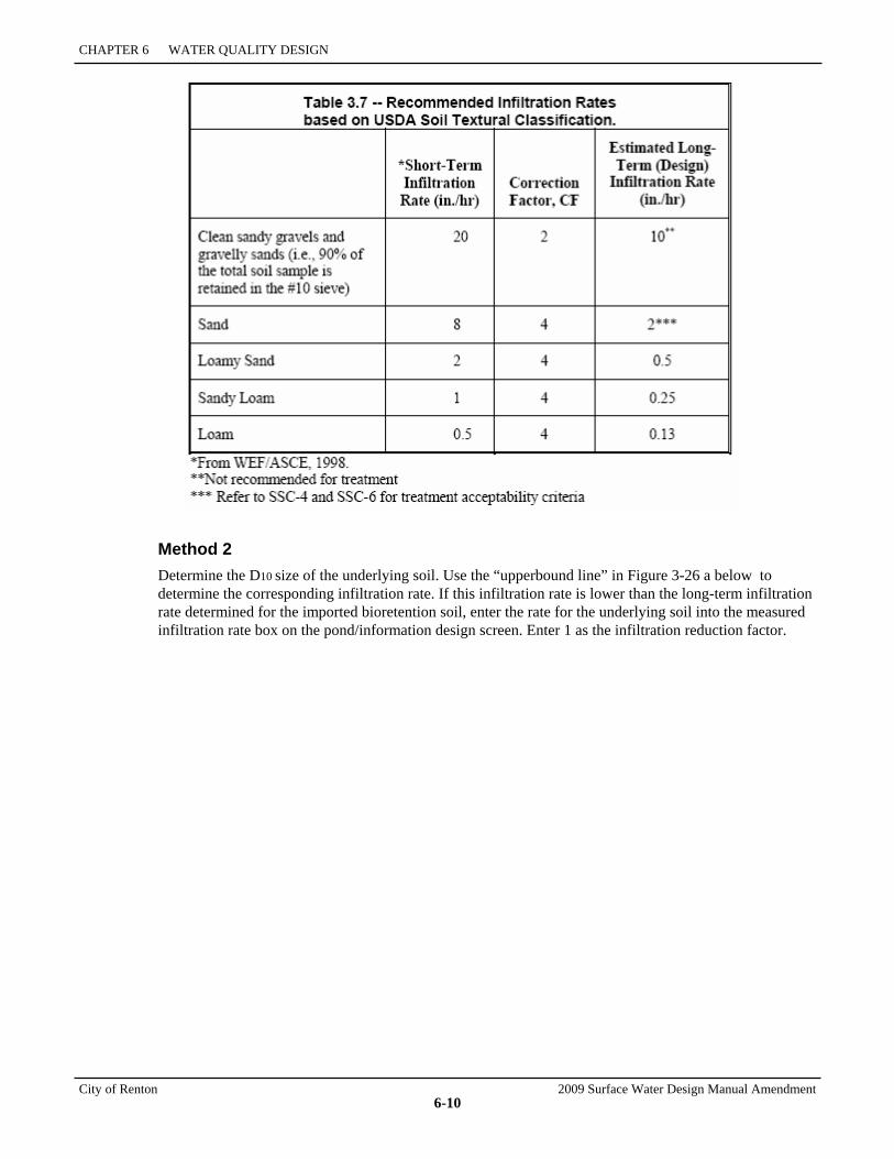
CHAPTER 6 WATER QUALITY DESIGN
City of Renton 2009 Surface Water Design Manual Amendment
6-10
Method 2 Determine the D10 size of the underlying soil. Use the “upperbound line” in Figure 3-26 a below to determine the corresponding infiltration rate. If this infiltration rate is lower than the long-term infiltration rate determined for the imported bioretention soil, enter the rate for the underlying soil into the measured infiltration rate box on the pond/information design screen. Enter 1 as the infiltration reduction factor.

2009 Surface Water Design Manual Amendment City of Renton
6-11
Figure 3.26
Method 3 Measure the in situ infiltration rate of the underlying soil using procedures (Pilot Infiltration Test) identified in section 5.4.1. If this rate is lower than the long-term infiltration rate determined for the imported bioretention soil, enter the underlying soil infiltration rate into the corresponding box on the pond information/design screen of the WWHM. Enter 1 as the infiltration reduction factor.
CHAPTER 6 WATER QUALITY DESIGN
City of Renton 2009 Surface Water Design Manual Amendment
6-12
6.7.1.7 WWHM ROUTING AND RUNOFF FILE EVALUATION In WWHM2, all infiltrating facilities must have an overflow riser to model overflows that occur should the available storage be exceeded. So in the Riser/Weir screen, for the Riser head enter a value slightly smaller than the effective depth of the pond (say 0.1 ft below the Effective Depth); and for the Riser diameter enter a large number (say 10,000 inches) to ensure that there is ample capacity for overflows.
Within the model, route the runoff into the pond by grabbing the pond icon and placing it below the tributary “basin” area. Be sure to include the surface area of the bioretention area in the tributary “basin” area. Run the model to produce the effluent runoff file from the theoretical pond. For projects subject to the flow control standard, compare the flow duration graph of that runoff file to the target pre-developed runoff file for compliance with the flow duration standard. If the standard is not achieved a downstream retention or detention facility must be sized (using the WWHM standard procedures) and located in the field. A conveyance system should be designed in accordance with the criteria specified in Chapter 4 Conveyance System Analysis and Design to route all overflows from the bioretention areas to centralized treatment facilities, and to flow control facilities if flow control applies to the project.
6.7.1.8 MODELING MULTIPLE RAIN GARDENS Where multiple rain gardens are scattered throughout a development, it may be possible to represent those as one rain garden (a “pond” in the WWHM) serving the cumulative area tributary to those rain gardens. For this to be a reasonable representation, the design of each rain garden should be similar (e.g., same depth of soil, same depth of surface ponded water, roughly the same ratio of impervious area to rain garden volume).
6.7.1.9 OTHER RAIN GARDENS DESIGN Guidance for modeling other bioretention designs is not yet available.
2009 Surface Water Design Manual Amendment City of Renton
DEFINITIONS
CITY OF RENTON AMENDMENTS TO THE KING COUNTY SURFACE WATER DESIGN MANUAL February 2010

2009 Surface Water Design Manual Amendment City of Renton
1
DEFINITIONS
The City of Renton has made the following changes to the Definitions section of the 2009 KCSWDM. Users should refer to the County document for all other definitions.
Agricultural project. Definition removed.
Aquifer Protection Area (APA) means the portion of an aquifer within the zone of capture and recharge area for a well or well field owned or operated by the City of Renton as depicted in RMC 4-3-050Q1 Maps, Aquifer Protection.
Construct or modify means to install a new drainage pipe/ditch or make improvements to an existing drainage pipe or ditch, for purposes other than maintenance,1 that either serves to concentrate previously unconcentrated surface and storm water runoff or serves to increase, decrease, or redirect the conveyance of surface and storm water runoff.
Critical aquifer recharge area. Definition removed.
Critical Drainage Area. Definition removed.
Erosion hazard area is the critical area designation, defined and regulated in RMC 4-3-050, that is applied to areas underlain by soils that are subject to severe erosion when disturbed. Such areas are delineated on the Erosion Hazards map, Figure 4-3-050Q3b(i) in the RMC.
Existing site conditions means those that existed prior to May 1979 as determined from aerial photographs and, if necessary, knowledge of individuals familiar with the area, unless a drainage plan for land cover changes has been approved by the City of Renton since May 1979 as part of a City permit or approval (or County-approved permit if in an area that has been annexed by the City). If so, existing site conditions are those created by the site improvements and drainage facilities constructed per the approved drainage plan.
Flood hazard area is the critical area designation, defined and regulated in RMC 4-3-050, that is applied to areas that are subject to flooding. Such areas are delineated on the Flood Hazards map, Figure 4-3-050Q2 in the RMC.
Groundwater protection areas include the Cedar Valley Sole Source Aquifer Project Review Area designated by the Environmental Protection Agency, Wellhead Protection Areas as mapped by the Washington State Department of Health, and the Aquifer Protection Area. The combined area described by these criteria is represented in Reference 11-B, Groundwater Protection Areas in the City of Renton.
High-use site means a commercial or industrial site that (1) has an expected average daily traffic (ADT) count equal to or greater than 100 vehicles per 1,000 square feet of gross building area; (2) is subject to petroleum storage or transfer in excess of 1,500 gallons per year, not including delivered heating oil; or (3) is subject to use, storage, or maintenance of a fleet of 25 or more vehicles that are over 10 tons net weight (trucks, buses, trains, heavy equipment, etc.). Also included is any road intersection with a measured ADT count of 25,000 vehicles or more on the main roadway and 15,000 vehicles or more on any intersecting roadway, excluding projects proposing primarily pedestrian or bicycle use improvements. For the purposes of this definition, commercial and industrial site means that portion of a site's developed area associated with an individual commercial or industrial business (e.g., the area occupied by the business's buildings and required parking).
1 Maintenance means those usual activities taken to prevent a decline, lapse, or cessation in the use of currently serviceable structures,
facilities, equipment, or systems if there is no expansion of the structure, facilities, equipment, or system and there are no significant hydrologic impacts. Maintenance includes the repair or replacement of non-functional facilities and the replacement of existing structures with different types of structures, if the repair or replacement is required to meet current engineering standards or is required by one or more environmental permits and the functioning characteristics of the original facility or structure are not changed. For the purposes of applying this definition to the thresholds and requirements of this manual, RDSD will determine whether the functioning characteristics of the original facility or structure will remain sufficiently unchanged to consider replacement as maintenance.
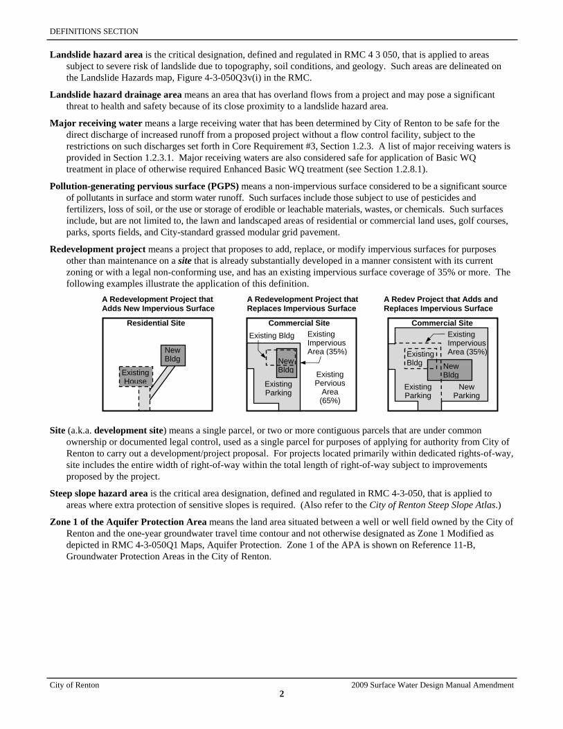
DEFINITIONS SECTION
City of Renton 2009 Surface Water Design Manual Amendment
2
Landslide hazard area is the critical designation, defined and regulated in RMC 4 3 050, that is applied to areas subject to severe risk of landslide due to topography, soil conditions, and geology. Such areas are delineated on the Landslide Hazards map, Figure 4-3-050Q3v(i) in the RMC.
Landslide hazard drainage area means an area that has overland flows from a project and may pose a significant threat to health and safety because of its close proximity to a landslide hazard area.
Major receiving water means a large receiving water that has been determined by City of Renton to be safe for the direct discharge of increased runoff from a proposed project without a flow control facility, subject to the restrictions on such discharges set forth in Core Requirement #3, Section 1.2.3. A list of major receiving waters is provided in Section 1.2.3.1. Major receiving waters are also considered safe for application of Basic WQ treatment in place of otherwise required Enhanced Basic WQ treatment (see Section 1.2.8.1).
Pollution-generating pervious surface (PGPS) means a non-impervious surface considered to be a significant source of pollutants in surface and storm water runoff. Such surfaces include those subject to use of pesticides and fertilizers, loss of soil, or the use or storage of erodible or leachable materials, wastes, or chemicals. Such surfaces include, but are not limited to, the lawn and landscaped areas of residential or commercial land uses, golf courses, parks, sports fields, and City-standard grassed modular grid pavement.
Redevelopment project means a project that proposes to add, replace, or modify impervious surfaces for purposes other than maintenance on a site that is already substantially developed in a manner consistent with its current zoning or with a legal non-conforming use, and has an existing impervious surface coverage of 35% or more. The following examples illustrate the application of this definition.
A Redevelopment Project that Adds New Impervious Surface
A Redevelopment Project that Replaces Impervious Surface
A Redev Project that Adds and Replaces Impervious Surface
Site (a.k.a. development site) means a single parcel, or two or more contiguous parcels that are under common ownership or documented legal control, used as a single parcel for purposes of applying for authority from City of Renton to carry out a development/project proposal. For projects located primarily within dedicated rights-of-way, site includes the entire width of right-of-way within the total length of right-of-way subject to improvements proposed by the project.
Steep slope hazard area is the critical area designation, defined and regulated in RMC 4-3-050, that is applied to areas where extra protection of sensitive slopes is required. (Also refer to the City of Renton Steep Slope Atlas.)
Zone 1 of the Aquifer Protection Area means the land area situated between a well or well field owned by the City of Renton and the one-year groundwater travel time contour and not otherwise designated as Zone 1 Modified as depicted in RMC 4-3-050Q1 Maps, Aquifer Protection. Zone 1 of the APA is shown on Reference 11-B, Groundwater Protection Areas in the City of Renton.
Existing House Existing
Parking
New Bldg
Existing Parking
New Parking
Existing Pervious
Area (65%)
Existing Impervious Area (35%) Existing
Bldg
Commercial SiteExisting Impervious Area (35%)
Commercial SiteResidential Site
New Bldg
Existing Bldg
New Bldg
2009 Surface Water Design Manual Amendment City of Renton
APPENDICES
CITY OF RENTON AMENDMENTS TO THE KING COUNTY SURFACE WATER DESIGN MANUAL February 2010
APPENDIX C Small Project Drainage Requirements
APPENDIX E City of Renton Standard Details

2009 Surface Water Design Manual Amendment City of Renton
APPENDIX C SMALL PROJECT DRAINAGE REQUIREMENTS
CITY OF RENTON AMENDMENTS TO THE KING COUNTY SURFACE WATER DESIGN MANUAL February 2010

2009 Surface Water Design Manual Amendment City of Renton
C-1
APPENDIX C SMALL PROJECT DRAINAGE REQUIREMENTS
The City of Renton has made the following changes to Appendix C of the 2009 KCSWDM.
DEFINITIONS OF KEY TERMS • This section is deleted in its entirety and replaced with the following (pp. C-3 to C-4):
Key terms and definitions used in this Addendum to the KCSWDM, including this Appendix, are contained in Chapter 1 and are not repeated here.
Three additional definitions not included in Chapter 1 include the following:
Engineering geologist means a person licensed by the State of Washington as a geologist specializing in evaluating geologic site characteristics to determine the responses of geologic processes and materials to development activities, such as removal of vegetation; construction activities such as earthwork; applying loads in foundations and embankments; use of earth materials in construction; and modifying ground water flow.
Geotechnical engineer means a civil engineer licensed by the State of Washington who has at least four years of professional employment as a geotechnical engineer in responsible charge, including experience with landslide evaluation. Geotechnical engineers specialize in the design and construction aspects of earth materials.
DDES Staff Geologist in this section means an engineer (or other assignee) with the City of Renton assigned to provide input to the applicant’s project.
C.1 SMALL PROJECT DRAINAGE REVIEW REQUIREMENTS • Delete first paragraph, subsequent three bullets, and note with the following (p. C-5):
Small Project Drainage Review is a simplified drainage review for small residential building, clearing, and subdivision projects that meet the threshold requirements of this section. The core and special requirements applied under Full Drainage Review are replaced with simplified small project drainage requirements that can be applied by a non-engineer. These requirements include simple stormwater dispersion, infiltration, and site design techniques called flow control Best Management Practices (BMPs), which provide the necessary mitigation of flow and water quality impacts for small projects. Also included are simple measures for erosion and sediment control (ESC). This simplified form of drainage review
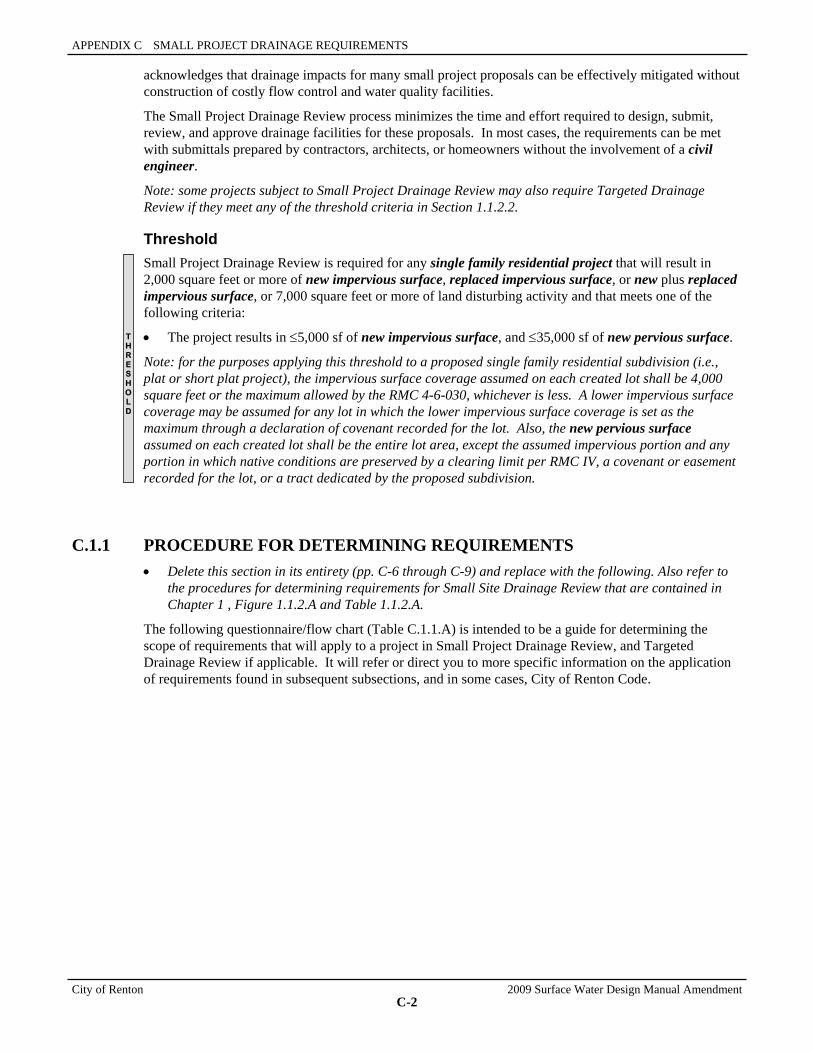
APPENDIX C SMALL PROJECT DRAINAGE REQUIREMENTS
City of Renton 2009 Surface Water Design Manual Amendment
C-2
acknowledges that drainage impacts for many small project proposals can be effectively mitigated without construction of costly flow control and water quality facilities.
The Small Project Drainage Review process minimizes the time and effort required to design, submit, review, and approve drainage facilities for these proposals. In most cases, the requirements can be met with submittals prepared by contractors, architects, or homeowners without the involvement of a civil engineer.
Note: some projects subject to Small Project Drainage Review may also require Targeted Drainage Review if they meet any of the threshold criteria in Section 1.1.2.2.
Threshold Small Project Drainage Review is required for any single family residential project that will result in 2,000 square feet or more of new impervious surface, replaced impervious surface, or new plus replaced impervious surface, or 7,000 square feet or more of land disturbing activity and that meets one of the following criteria:
• The project results in ≤5,000 sf of new impervious surface, and ≤35,000 sf of new pervious surface.
Note: for the purposes applying this threshold to a proposed single family residential subdivision (i.e., plat or short plat project), the impervious surface coverage assumed on each created lot shall be 4,000 square feet or the maximum allowed by the RMC 4-6-030, whichever is less. A lower impervious surface coverage may be assumed for any lot in which the lower impervious surface coverage is set as the maximum through a declaration of covenant recorded for the lot. Also, the new pervious surface assumed on each created lot shall be the entire lot area, except the assumed impervious portion and any portion in which native conditions are preserved by a clearing limit per RMC IV, a covenant or easement recorded for the lot, or a tract dedicated by the proposed subdivision.
C.1.1 PROCEDURE FOR DETERMINING REQUIREMENTS • Delete this section in its entirety (pp. C-6 through C-9) and replace with the following. Also refer to
the procedures for determining requirements for Small Site Drainage Review that are contained in Chapter 1 , Figure 1.1.2.A and Table 1.1.2.A.
The following questionnaire/flow chart (Table C.1.1.A) is intended to be a guide for determining the scope of requirements that will apply to a project in Small Project Drainage Review, and Targeted Drainage Review if applicable. It will refer or direct you to more specific information on the application of requirements found in subsequent subsections, and in some cases, City of Renton Code.
T H R E S H O L D
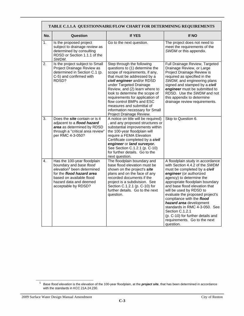
2009 Surface Water Design Manual Amendment City of Renton
C-3
TABLE C.1.1.A QUESTIONNAIRE/FLOW CHART FOR DETERMINING REQUIREMENTS
No. Question If YES If NO
1. Is the proposed project subject to drainage review as determined by consulting RDSD or Section 1.1.1 of the SWDM.
Go to the next question. The project does not need to meet the requirements of the SWDM or this appendix.
2. Is the project subject to Small Project Drainage Review as determined in Section C.1 (p. C-5) and confirmed with RDSD?
Step through the following questions to (1) determine the scope of requirements, if any, that must be addressed by a civil engineer and/or RDSD under Targeted Drainage Review, and (2) learn where to look to determine the scope of requirements for application of flow control BMPs and ESC measures and submittal of information necessary for Small Project Drainage Review.
Full Drainage Review, Targeted Drainage Review, or Large Project Drainage Review is required as specified in the SWDM, and engineering plans signed and stamped by a civil engineer must be submitted to RDSD. Use the SWDM and not this appendix to determine drainage review requirements.
3. Does the site contain or is it adjacent to a flood hazard area as determined by RDSD through a "critical area review" per RMC 4-3-050?
A notice on title will be required) , and any proposed structures or substantial improvements within the 100-year floodplain will require a FEMA Elevation Certificate completed by a civil engineer or land surveyor. See Section C.1.2.1 (p. C-10) for further details. Go to the next question.
Skip to Question 6.
A floodplain study in accordance with Section 4.4.2 of the SWDM must be completed by a civil engineer (or authorized agency) to determine the appropriate floodplain boundary and base flood elevation that will be used by RDSD to evaluate the proposed project's compliance with the flood hazard area development standards in RMC 4-3-050. See Section C.1.2.1
4. Has the 100-year floodplain boundary and base flood elevation1 been determined for the flood hazard area based on available flood hazard data and deemed acceptable by RDSD?
The floodplain boundary and base flood elevation must be shown on the project's site plans and on the face of any recorded documents if the project is a subdivision. See Section C.1.2.1 (p. C-10) for further details. Go to the next question.
(p. C-10) for further details and requirements. Go to the next question.
1 Base flood elevation is the elevation of the 100-year floodplain, at the project site, that has been determined in accordance
with the standards in KCC 21A.24.230.
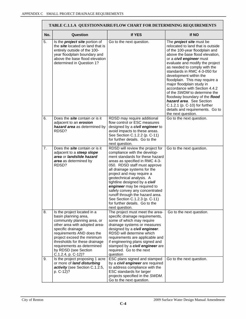
APPENDIX C SMALL PROJECT DRAINAGE REQUIREMENTS
City of Renton 2009 Surface Water Design Manual Amendment
C-4
TABLE C.1.1.A QUESTIONNAIRE/FLOW CHART FOR DETERMINING REQUIREMENTS
No. Question If YES If NO
5. Is the project site portion of the site located on land that is entirely outside of the 100-year floodplain boundary and above the base flood elevation determined in Question 1?
Go to the next question. The project site must be relocated to land that is outside of the 100-year floodplain and above the base flood elevation, or a civil engineer must evaluate and modify the project as needed to comply with the standards in RMC 4-3-050 for development within the floodplain. This may require a major floodplain study in accordance with Section 4.4.2 of the SWDM to determine the floodway boundary of the flood hazard area. See Section C.1.2.1 (p. C-10) for further details and requirements. Go to the next question.
6. Does the site contain or is it adjacent to an erosion hazard area as determined by RDSD?
RDSD may require additional flow control or ESC measures designed by a civil engineer to avoid impacts to these areas. See Section C.1.2.2 (p. C-11) for further details. Go to the next question.
Go to the next question.
7. Does the site contain or is it adjacent to a steep slope area or landslide hazard area as determined by RDSD?
RDSD will review the project for compliance with the develop-ment standards for these hazard areas as specified in RMC 4-3-050. RDSD staff must approve all drainage systems for the project and may require a geotechnical analysis. A tightline designed by a civil engineer may be required to safely convey any concentrated runoff through the hazard area. See Section C.1.2.3 (p. C-11) for further details. Go to the next question.
Go to the next question.
8. Is the project located in a basin planning area, community planning area, or other area with adopted area-specific drainage requirements AND does the project exceed the minimum thresholds for these drainage requirements as determined by RDSD (see Section C.1.2.4, p. C-12)?
The project must meet the area-specific drainage requirements, some of which may require drainage systems or measures designed by a civil engineer. RDSD will determine which requirements are applicable and if engineering plans signed and stamped by a civil engineer are required. Go to the next question
Go to the next question.
9. Is the project proposing 1 acre or more of land disturbing activity (see Section C.1.2.5, p. C-12)?
ESC plans signed and stamped by a civil engineer are required to address compliance with the ESC standards for larger projects specified in the SWDM. Go to the next question.
Go to the next question.

2009 Surface Water Design Manual Amendment City of Renton
C-5
TABLE C.1.1.A QUESTIONNAIRE/FLOW CHART FOR DETERMINING REQUIREMENTS
No. Question If YES If NO
10. Is the project proposing to construct or modify a drainage pipe or ditch that is 12 inches or more in diameter/depth, or does the project site receive surface or storm water from a drainage pipe or ditch that is 12 inches or more in diameter/depth (see Section C.1.2.6, p. C-12)?
Engineering plans signed and stamped by a civil engineer are required to address compliance with the Targeted Drainage Review requirements pertaining to constructed or modified conveyance systems in the SWDM. Go to the next question.
Go to the next question.
11. Are there any other drainage features onsite (swales, ditches, etc.) that may impact the proposed project or downstream properties or be impacted by the project?
Engineering analysis by a civil engineer may be required. RDSD staff will need to assess features. Go to the next question.
Go to the next question.
12. Is the proposed project on a site/lot smaller than 22,000 square feet?
Apply flow control BMPs in accordance with the Small Lot BMP Requirements in Section C.1.3.1 (p. C-13) and the Flow Control BMP Implementation Requirements in Section C.1.3.3 (p. C-18). Apply ESC measures in accordance with Section C.1.4 (p. C-20). Comply with the small project submittal requirements in Section C.1.5 (p. C-23)
Apply flow control BMPs in compliance with the Large Lot BMP Requirements in Section C.1.3.2 (p. C-15) and the Flow Control BMP Implementation Requirements in Section C.1.3.3 (p. C-18). Apply ESC measures in accordance with Section C.1.4 (p. C-20). Comply with the small project submittal requirements in Section C.1.5 (p. C-23)
C.1.2.1 FLOOD HAZARD AREAS • References to requirements for development in channel migration zones do not apply (p. C-10).
• In the second paragraph on p. C-11, delete reference to KCC 21A.24.170 and its associated public rule.
C.1.2.2 EROSION HAZARD AREAS • Delete reference to KCC 21A.24.
C.1.3.1 SMALL LOT BMP REQUIREMENTS • Delete paragraph B. MITIGATION OF NEW PERVIOUS SURFACE in its entirety (p. C-14), and
replace with the following:
For projects subject to small lot BMP requirements, no flow control BMPs are required for new pervious surface. However, the City requires amendment of the soil to mitigate for lost moisture holding capacity in any area that has been compacted or that has had some or all of the duff layer or underlying topsoil removed. The duff layer and native topsoil shall be retained in an undisturbed state to the maximum extent
APPENDIX C SMALL PROJECT DRAINAGE REQUIREMENTS
City of Renton 2009 Surface Water Design Manual Amendment
C-6
practicable. Any duff layer or topsoil removed during grading shall be stockpiled onsite in a designated, controlled area not adjacent to public resources and critical areas. The material shall be reapplied to other portions of the site where feasible. Except as otherwise noted below, areas that have been cleared and graded shall have the soil moisture holding capacity restored to that of the original undisturbed soil native to the site to the maximum extent practicable. The soil in any area that has been compacted or that has had some or all of the duff layer or underlying topsoil removed shall be amended to mitigate for lost moisture-holding capacity. The amendment shall take place between May 1 and October 1. Replaced topsoil shall be a minimum of 8 inches thick, unless the applicant demonstrates that a different thickness will provide conditions equivalent to the soil moisture-holding capacity native to the site. Replaced topsoil shall have an organic matter content of between 8 and 13 percent dry weight and a pH suitable for the proposed landscape plants (for most soils in Renton, 4 inches of well-rotted compost tilled into the top 8 inches of soil is sufficient to achieve the organic content standard). This requirement does not apply to areas that at project completion are covered by an impervious surface, incorporated into a drainage facility, or engineered as structural fill or slope.
C.1.3.2 LARGE LOT BMP REQUIREMENTS • References to “Rural Stewardship Plan” or “Farm Management Plan” do not apply (p. C-15).
A. MITIGATION OF IMPERVIOUS SURFACE
• In the third sentence of paragraph #1 (p. C-15), delete the words “clearing limit per KCC 16.82 or by.”
B. MITIGATION OF NEW PERVIOUS SURFACE
• In the third sentence of paragraph #1 (p. C-16), delete the words “clearing limit per KCC 16.82 or by.”
• Delete the Note and replace with the following (p. C-16):
Note: In addition to the above requirements, the City requires amendment of the soil to mitigate for lost moisture holding capacity in any area that has been compacted or that has had some or all of the duff layer or underlying topsoil removed. The duff layer and native topsoil shall be retained in an undisturbed state to the maximum extent practicable. Any duff layer or topsoil removed during grading shall be stockpiled onsite in a designated, controlled area not adjacent to public resources and critical areas. The material shall be reapplied to other portions of the site where feasible. Except as otherwise noted below, areas that have been cleared and graded shall have the soil moisture holding capacity restored to that of the original undisturbed soil native to the site to the maximum extent practicable. The soil in any area that has been compacted or that has had some or all of the duff layer or underlying topsoil removed shall be amended to mitigate for lost moisture-holding capacity. The amendment shall take place between May 1 and October 1. Replaced topsoil shall be a minimum of 8 inches thick, unless the applicant demonstrates that a different thickness will provide conditions equivalent to the soil moisture-holding capacity native to the site. Replaced topsoil shall have an organic matter content of between 8 and 13 percent dry weight and a pH suitable for the proposed landscape plants (for most soils in Renton, 4 inches of well-rotted compost tilled into the top 8 inches of soil is sufficient to achieve the organic content standard). This requirement does not apply to areas that at project completion are covered by an impervious surface, incorporated into a drainage facility, or engineered as structural fill or slope.
2009 Surface Water Design Manual Amendment City of Renton
C-7
C.2. FLOW CONTROL BMPS
Other Resources • In the second sentence of the first paragraph (p. C-25), change the reference for Ecology’s
Stormwater Management Manual for Western Washington from August 2001 to 2005.
C.2.1.1 MINIMUM DESIGN REQUIREMENTS FOR FULL DISPERSION • In the first sentence of paragraph #1 (p. C-26), delete the words “clearing limit per KCC 16.82 or by
a.”
C.2.7 RAINWATER HARVESTING
Design Considerations • In the first sentence (p. C-42), replace “State UBC” with “most recent copy of the International
Building Code.”
C.4.2.1 GENERAL INFORMATION
Topography • In the third bulleted paragraph (p. C-114), replace “NGVD 1929” with “NAVD 1988.”
C.5.2 DECLARATION OF COVENANT AND GRANT OF EASEMENT FORM • Replace the form provided (p. C-125) with the form in Reference 8-M.

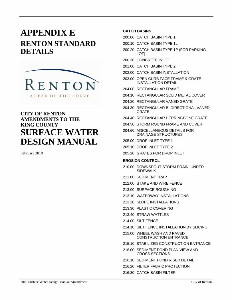
2009 Surface Water Design Manual Amendment City of Renton
APPENDIX E RENTON STANDARD DETAILS
CITY OF RENTON AMENDMENTS TO THE KING COUNTY SURFACE WATER DESIGN MANUAL February 2010
CATCH BASINS 200.00 CATCH BASIN TYPE 1 200.10 CATCH BASIN TYPE 1L 200.20 CATCH BASIN TYPE 1P (FOR PARKING
LOT) 200.30 CONCRETE INLET 201.00 CATCH BASIN TYPE 2 202.00 CATCH BASIN INSTALLATION 203.00 OPEN CURB FACE FRAME & GRATE
INSTALLATION DETAIL 204.00 RECTANGULAR FRAME 204.10 RECTANGULAR SOLID METAL COVER 204.20 RECTANGULAR VANED GRATE 204.30 RECTANGULAR BI-DIRECTIONAL VANED
GRATE 204.40 RECTANGULAR HERRINGBONE GRATE 204.50 STORM ROUND FRAME AND COVER 204.60 MISCELLANEOUS DETAILS FOR
DRAINAGE STRUCTURES 205.00 DROP INLET TYPE 1 205.10 DROP INLET TYPE 2 205.20 GRATES FOR DROP INLET
EROSION CONTROL 210.00 DOWNSPOUT STORM DRAIN, UNDER
SIDEWALK 211.00 SEDIMENT TRAP 212.00 STAKE AND WIRE FENCE 213.00 SURFACE ROUGHING 213.10 WATERWAY INSTALLATIONS 213.20 SLOPE INSTALLATIONS 213.30 PLASTIC COVERING 213.40 STRAW WATTLES 214.00 SILT FENCE 214.10 SILT FENCE INSTALLATION BY SLICING 215.00 WHEEL WASH AND PAVED
CONSTRUCTION ENTRANCE 215.10 STABILIZED CONSTRUCTION ENTRANCE 216.00 SEDIMENT POND PLAN VIEW AND
CROSS SECTIONS 216.10 SEDIMENT POND RISER DETAIL 216.20 FILTER FABRIC PROTECTION 216.30 CATCH BASIN FILTER
City of Renton 2009 Surface Water Design Manual Amendment
216.40 BLOCK AND GRAVEL CURB INLET PROTECTION
216.50 CURB AND GUTTER BARRIER PROTECTION
217.00 INTERCEPTOR DIKE 217.10 INTERCEPTOR SWALE 217.30 PIPE SLOPE DRAIN 217.40 CHECK DAMS SPACING AND CROSS
SECTIONS 217.50 LEVEL SPREADER DETAIL AND CROSS
SECTION 218.00 SAMPLE SMALL SITE EROSION CONTROL
PLAN
PIPES 220.00 PIPE COMPACTION DESIGN AND
BACKFILL 221.00 BEVELED END SECTIONS 221.10 FLARED END SECTIONS 221.20 DETAILS FOR COUPLING BANDS FOR
CORRUGATED METAL PIPES 221.30 STRAP PIPE ANCHOR DETAIL 221.40 COUPLING BANDS FOR CORRUGATED
METAL PIPES TYPE D 221.50 TYPE F COUPLING BANDS FOR
CORRUGATED METAL PIPES 222.00 HEADWALLS FOR CULVERT PIPE AND
UNDERPASS 222.10 TYPE 1 SAFETY BARS FOR STEPPED
CULVERT PIPE OR PIPE ARCH 222.20 TYPE 2 SAFETY BARS FOR CULVERT
PIPE OR PIPE ARCH (ON CROSS ROADS) 223.00 DEBRIS BARRIER 223.10 DEBRIS BARRIER FOR CONCRETE PIPE 224.00 50 FOOT FLOW DISPERSION TRENCH
WITH NOTCHED BOARD 225.00 TYPICAL ROOF DRAIN COLLECTION
STORM SYSTEM CIVIL PLANS 225.10 TYPICAL PRIVATE ROOF DRAIN
COLLECTION SYSTEM CROSS SECTION 225.20 SINGLE FAMILY ROOF DOWNSPOUT
INFILTRATION TRENCH
FLOW CONTROL 234.00 TYPICAL DETENTION POND 234.10 TYPICAL DETENTION POND SECTIONS 234.20 OVERFLOW STRUCTURE
235.00 TYPICAL DETENTION TANK 235.10 DETENTION TANK ACCESS DETAIL 236.00 TYPICAL DETENTION VAULT 237.00 FLOW RESTRICTOR /OIL POLLUTION
CONTROL TEE 237.10 FLOW RESTRICTOR /OIL POLLUTION
CONTROL BAFFLE 237.20 FLOW RESTRICTOR /OIL POLLUTION
CONTROL WEIR 237.30 FROP - T - SHEAR GATE DETAIL 238.00 TYPICAL INFILTRATION POND 238.10 TYPICAL INFILTRATION TANK
WATER QUALITY TREATMENT 240.00 BAFFLE OIL / WATER SEPARATOR 240.10 COALESCING PLATE OIL / WATER
SEPARATOR 241.00 FLOW SPLITTER - OPTION A 241.10 FLOW SPLITTER - OPTION B 242.00 FLOW SPREADER - OPTION A /
ANCHORAGE PLATE 242.10 FLOW SPREADER OPTION B / CONCRETE
SUMP BOX 243.00 BIOFILTRATION SWALE SCHEMATIC,
CROSS SECTION AND UNDERDRAIN DETAIL
248.00 STORMFILTER SCHEMATIC 249.00 TYPICAL WETPOND 249.10 TYPICAL WETPOND SECTIONS 249.20 WETVAULT 249.30 STORMWATER WETLAND OPTION A
COMBINED FLOW CONTROL AND WATER QUALITY TREATMENT 252.00 COMBINED DETENTION AND WETPOND 252.10 COMBINED DETENTION AND WETPOND -
SECTIONS 253.00 COMBINED DETENTION AND
STORMWATER WETLAND SECTIONS 254.00 COMBINED DETENTION AND WETVAULT
KING COUNTY DETAILS ADOPTED BY CITY OF RENTON 7-002 FIELD-TAPPING OF CONCRETE PIPE
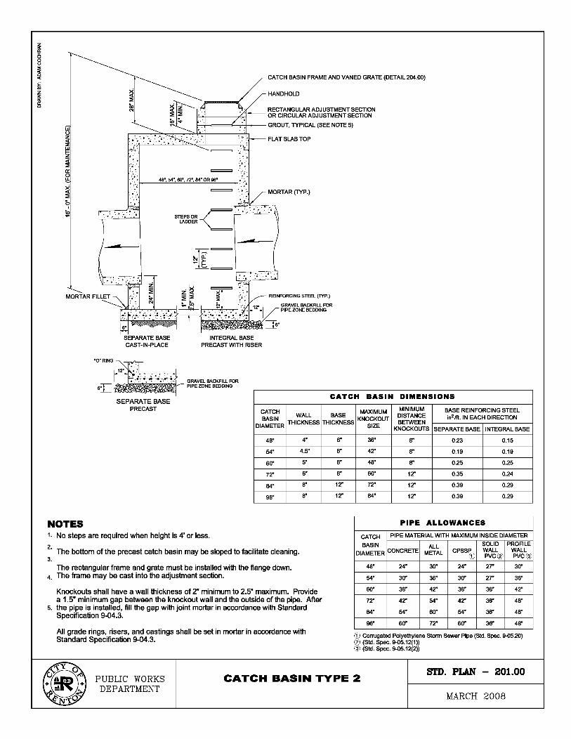
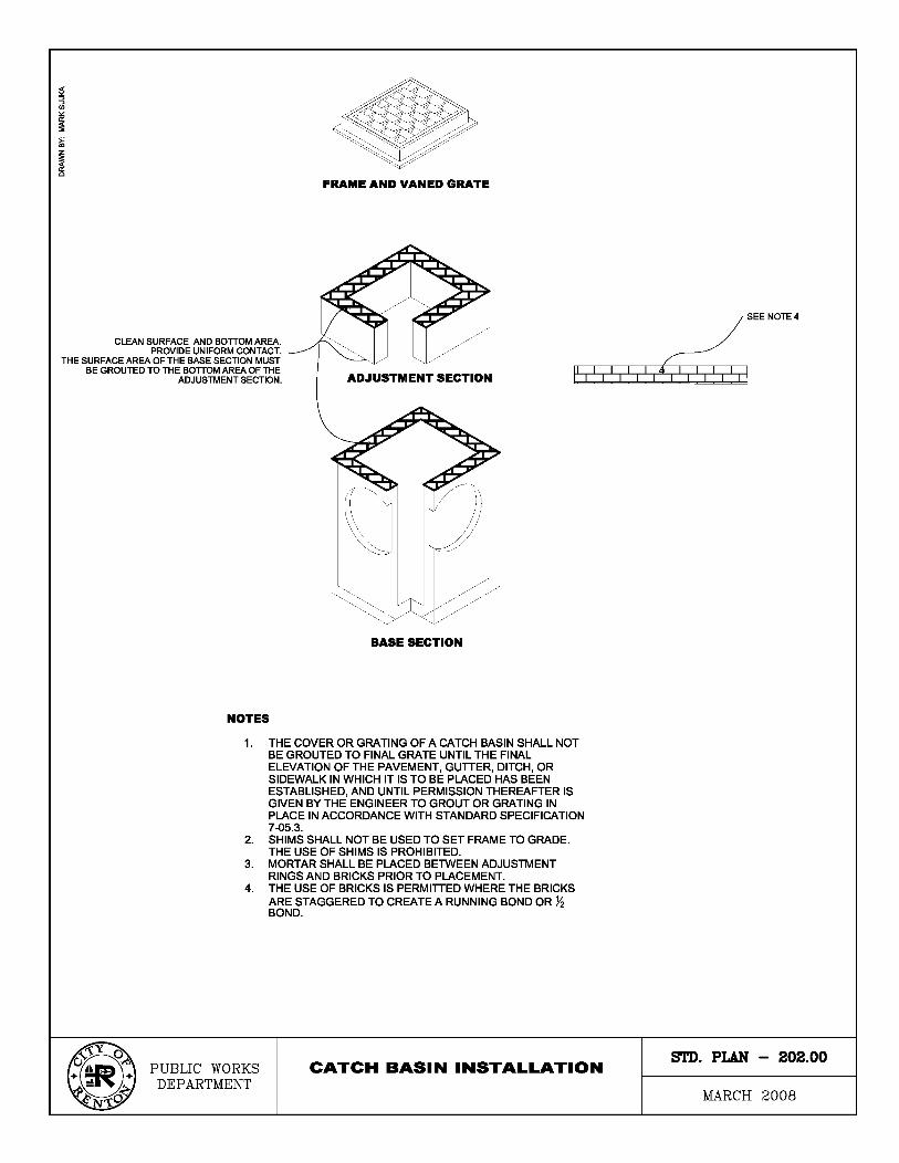

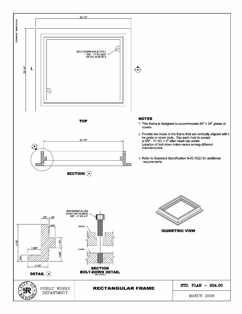
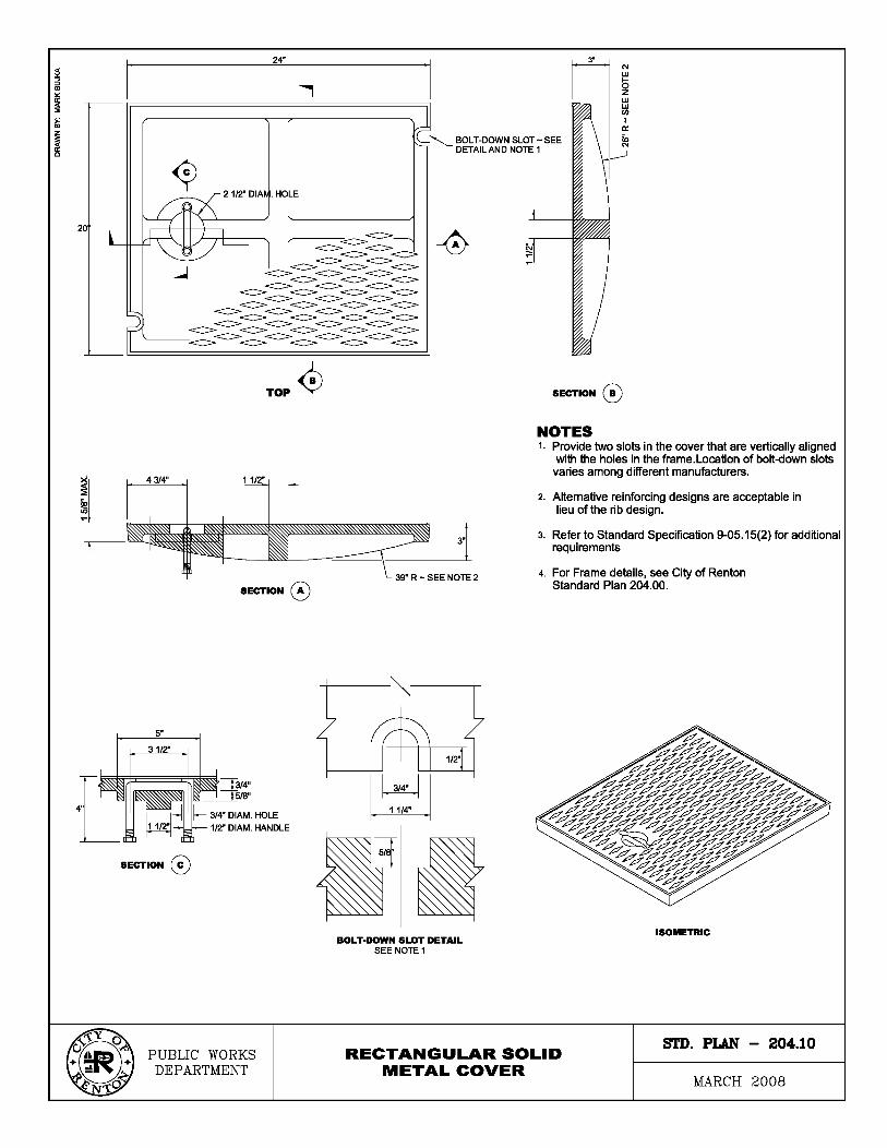

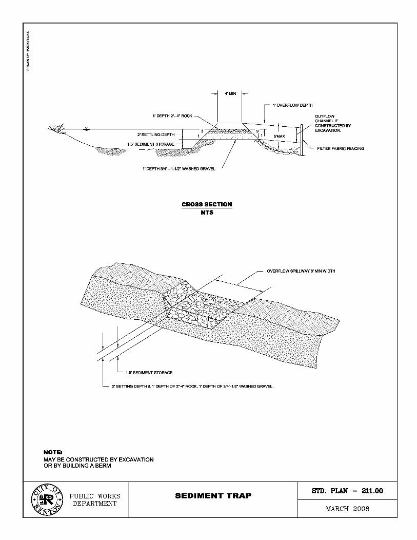

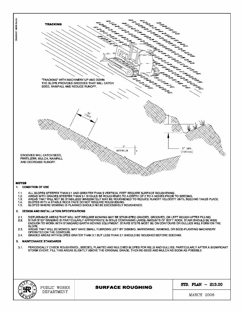

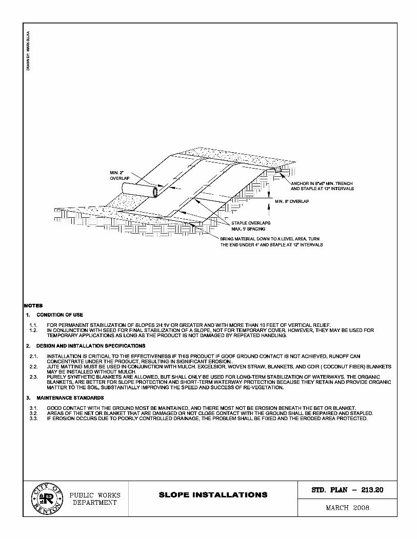
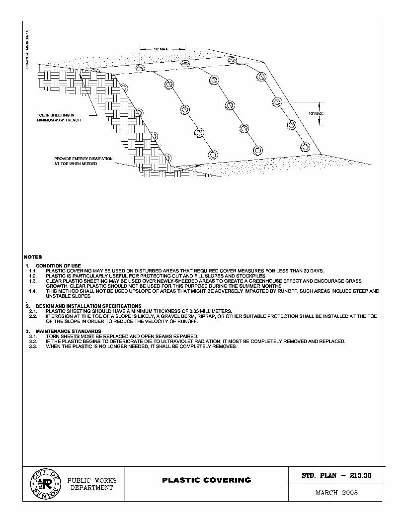
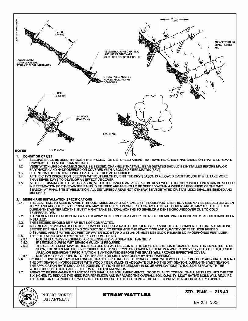
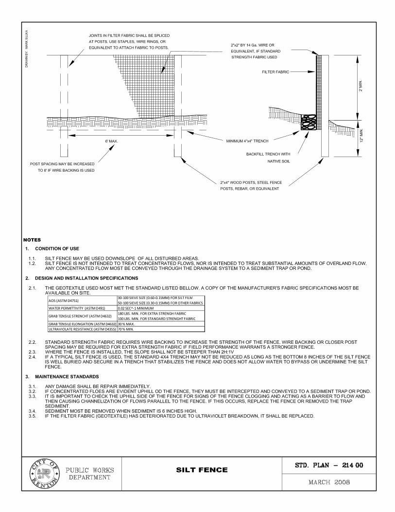
������������� ������������������������������ ��������������
������������������������������ ������������������
� �������������������������� � ���!����"�����# ��$�
%������# ���������# �������������! �&���������# �������'��������# %��������
�����������# ���������#���������# %���������
%������# ��������# %����# ����������! ���( ���'�
$�������������������# ������������� ��( ���# �
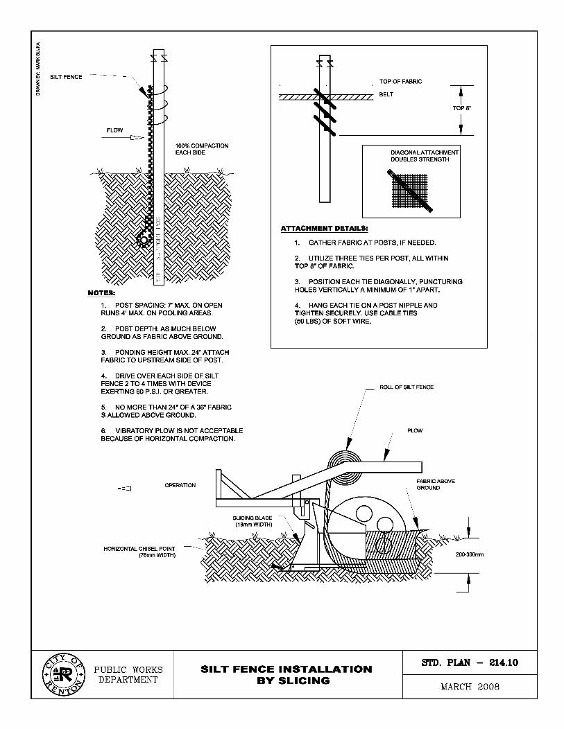
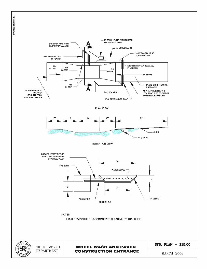
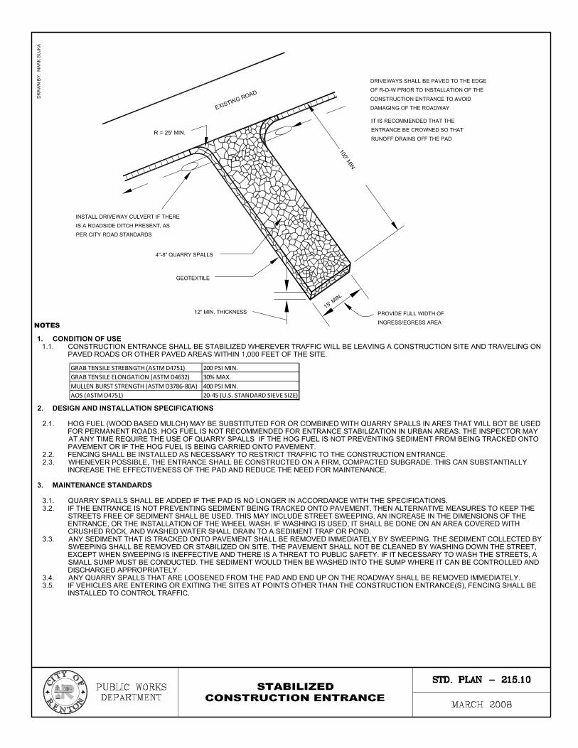
�������������������� ����������� ���������
��������������������� ����������� ��� �����
�������������������� ��������� ���� ���������
�� � ���������� �� ��� �������������!��"��
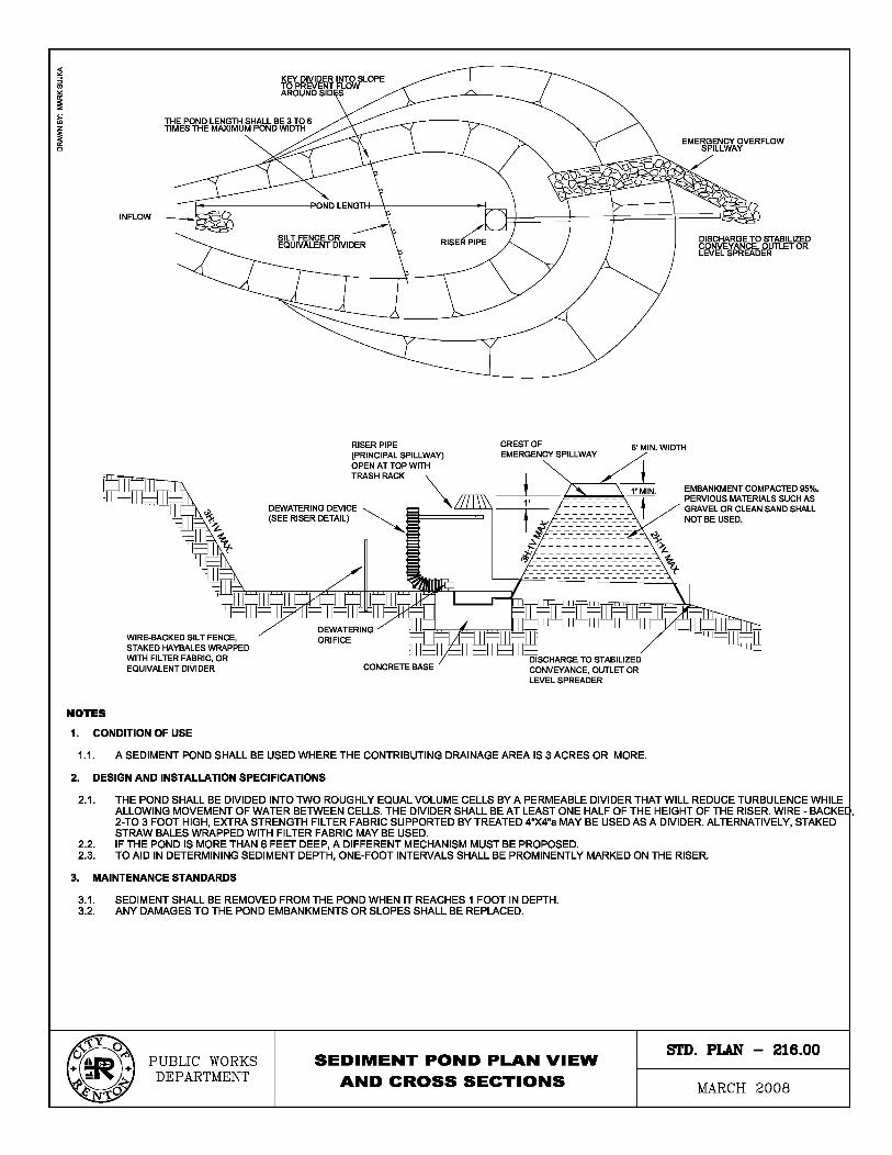
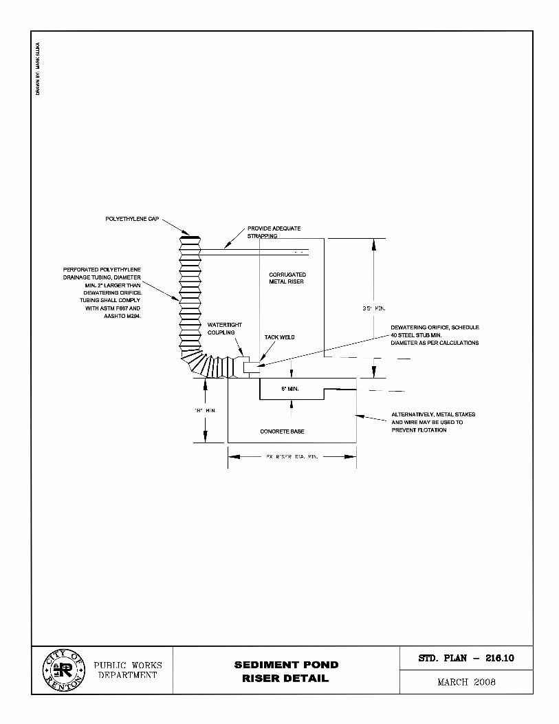
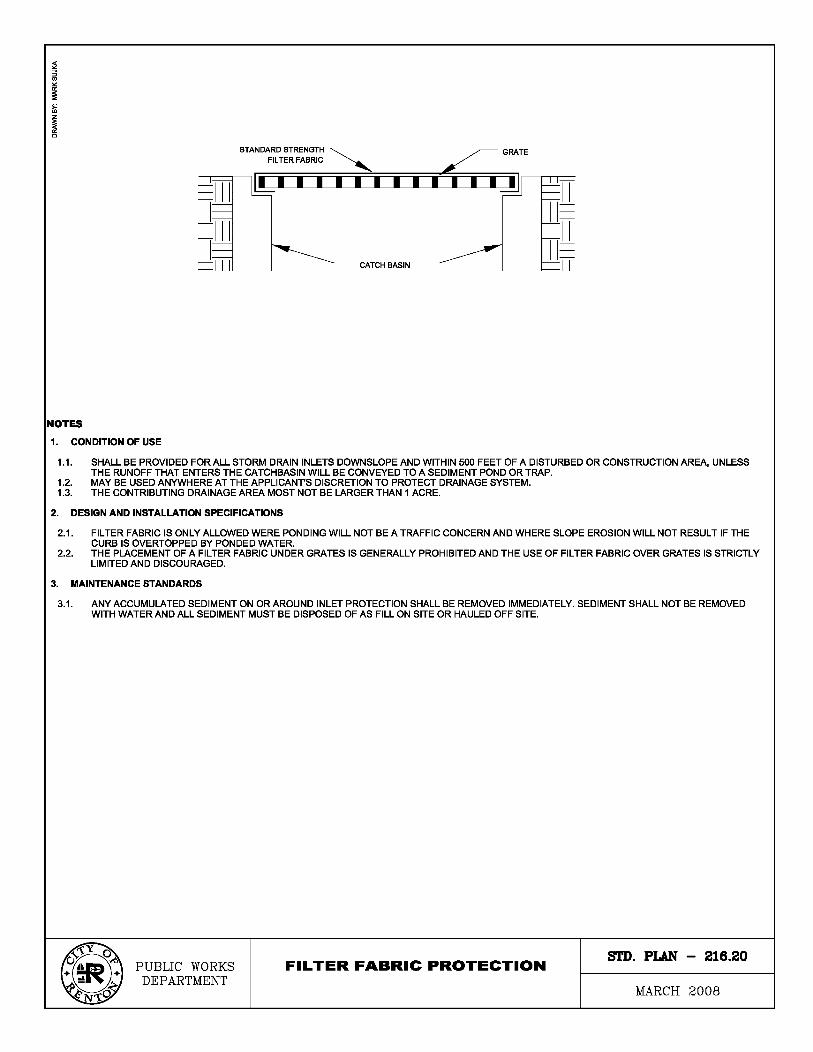
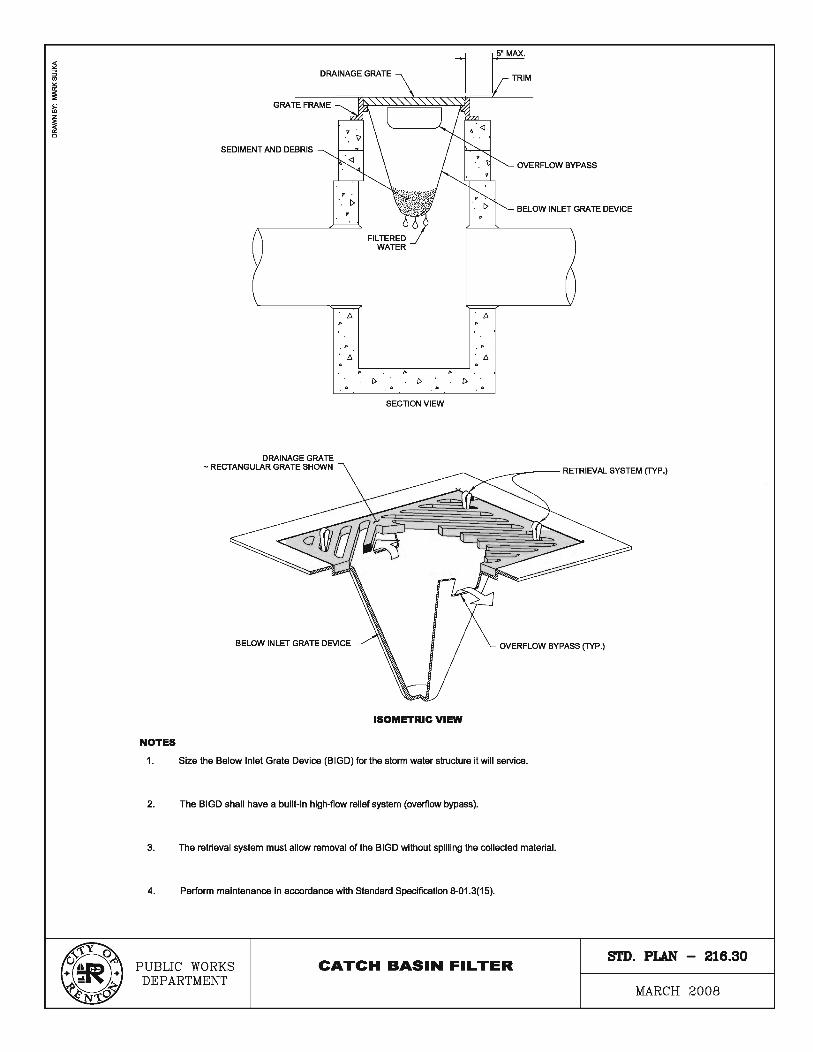
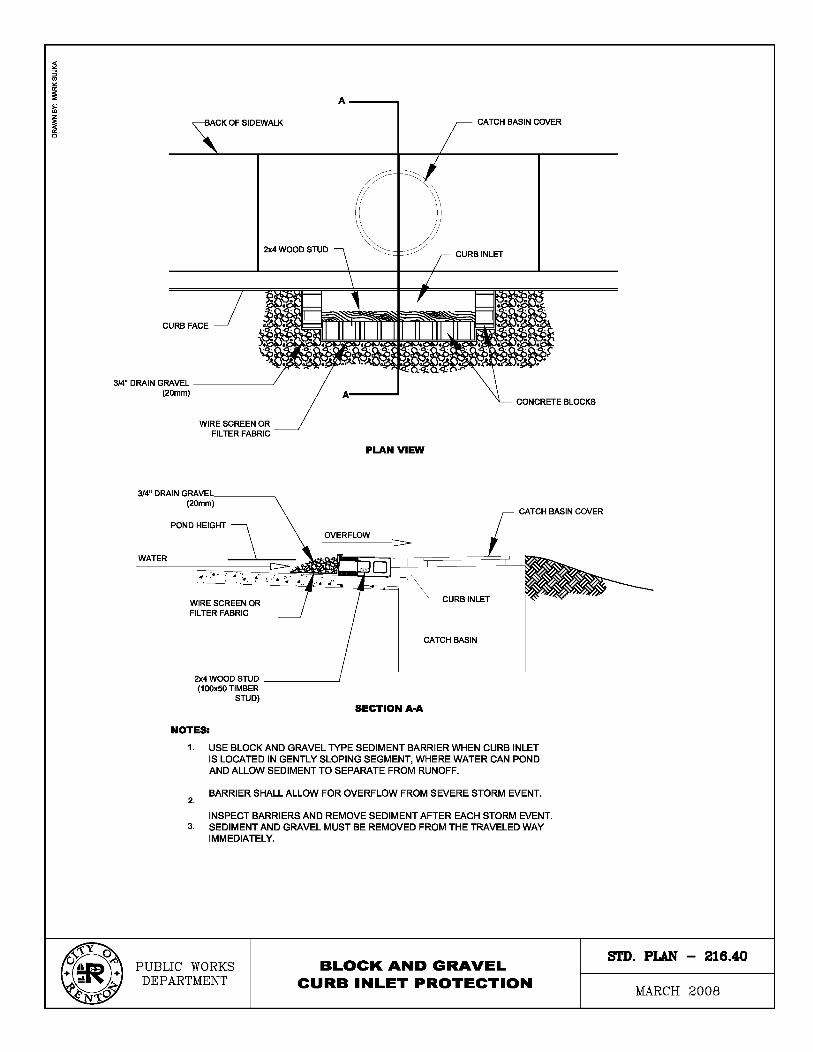

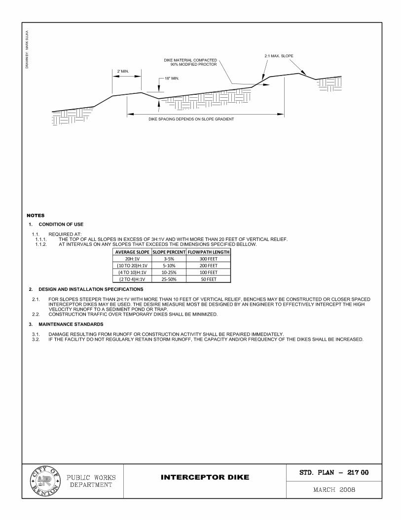
����������� ��������� ��� � ������ �
������ �� ����� �
������ �������� ��� ����� �
����� �������� ���� ����� �
����� ������� ��� ��� �
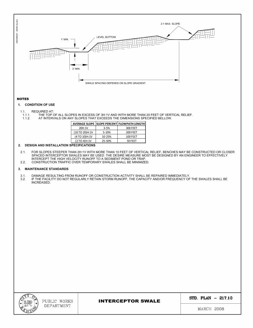
����������� ��������� ��� � ������ �
������ �� ����� �
������ �������� ��� ����� �
����� �������� ���� ����� �
����� ������� ��� ��� �
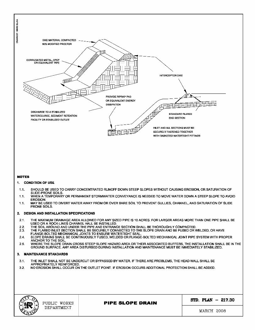
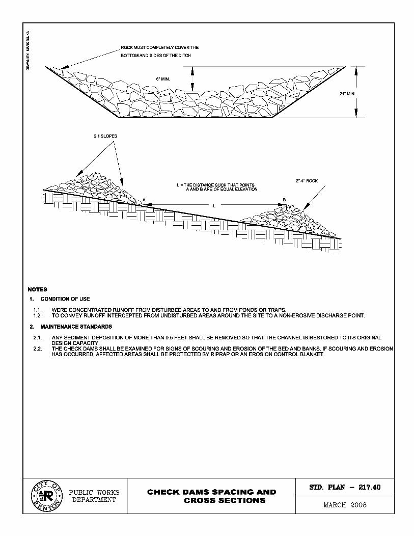
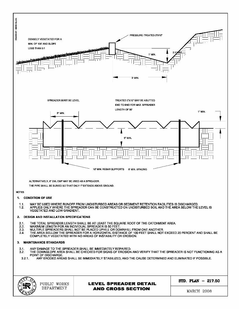
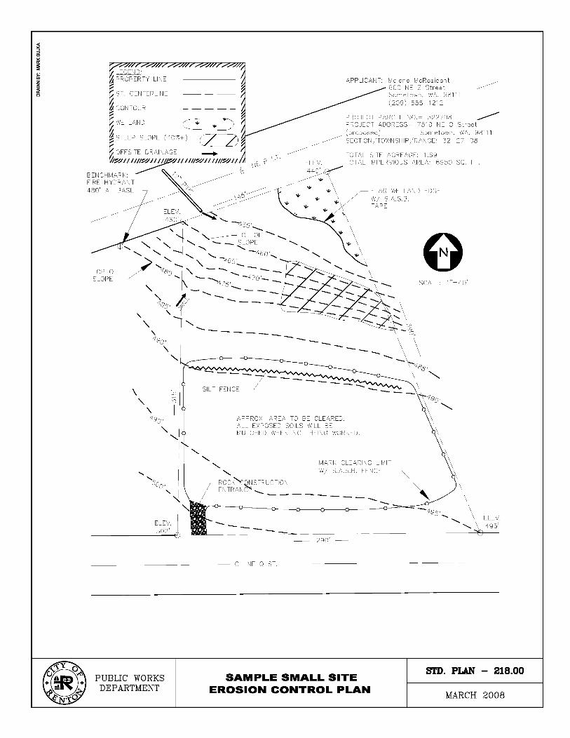
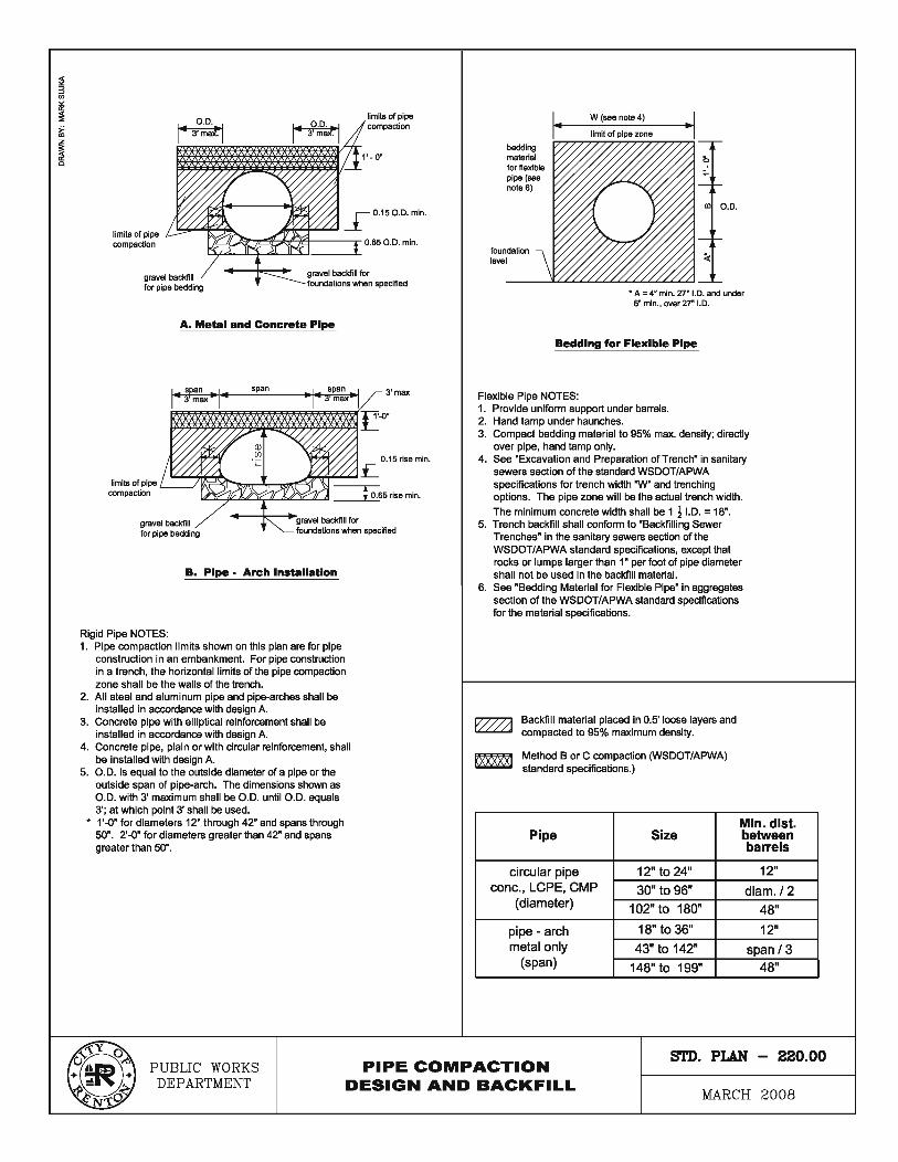
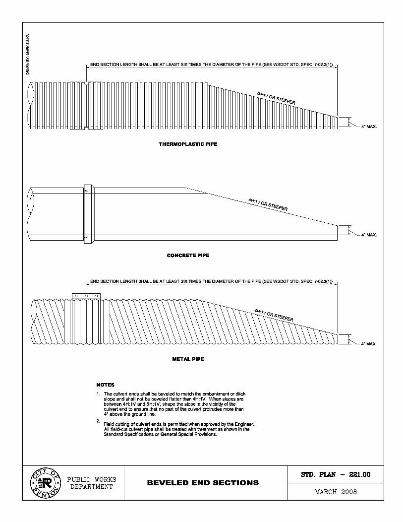
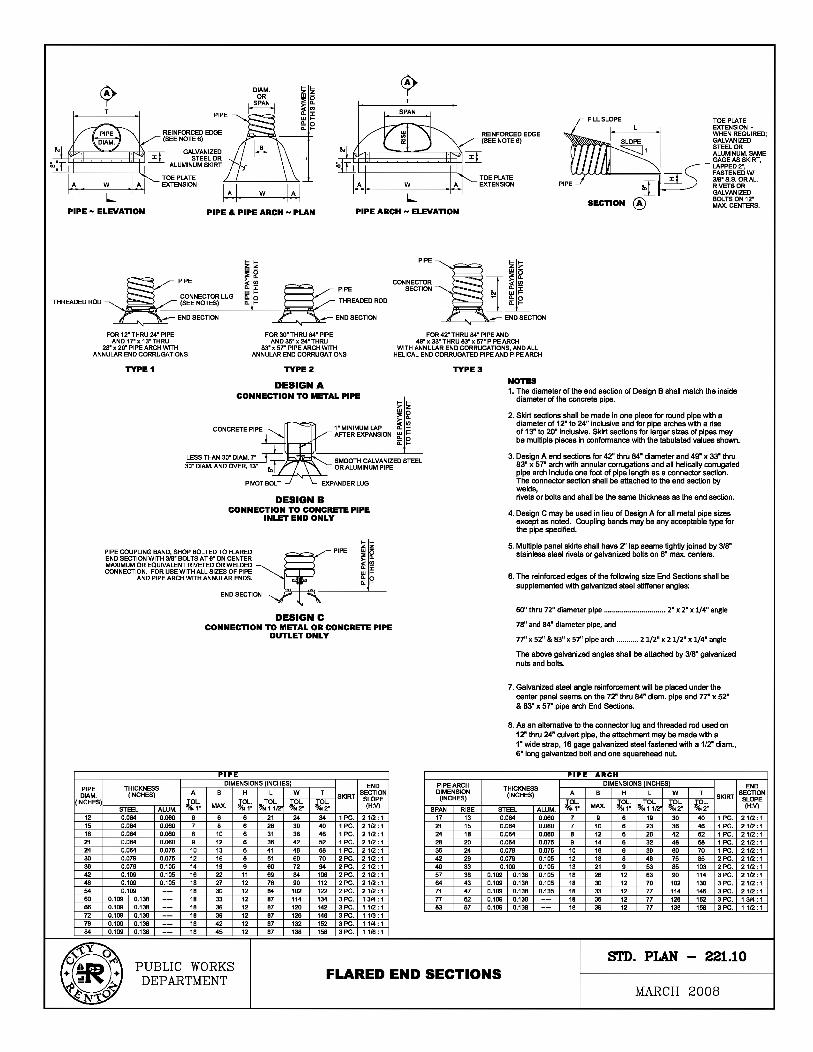
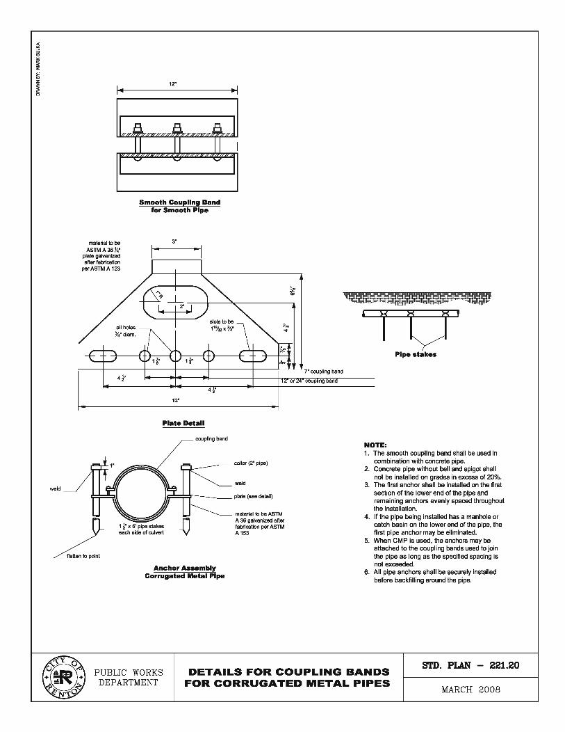
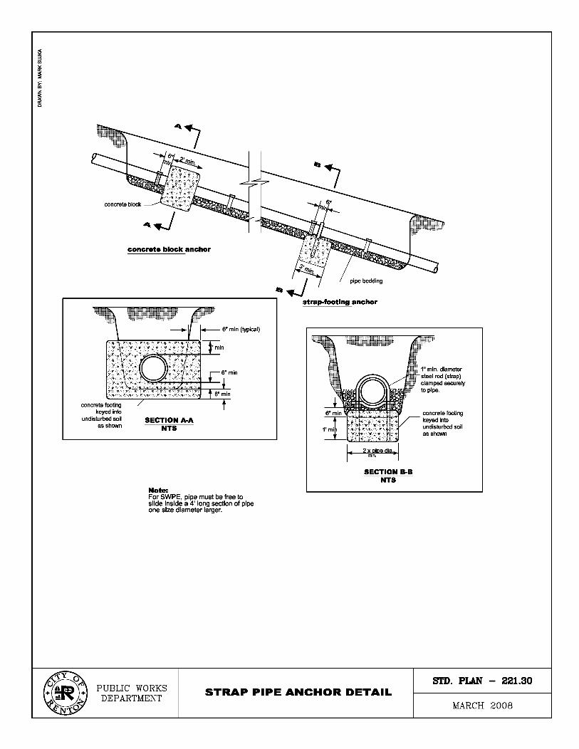
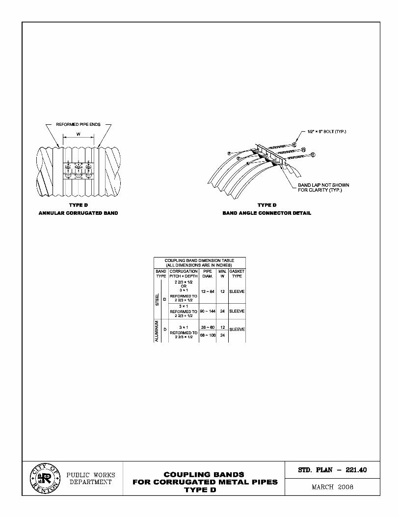

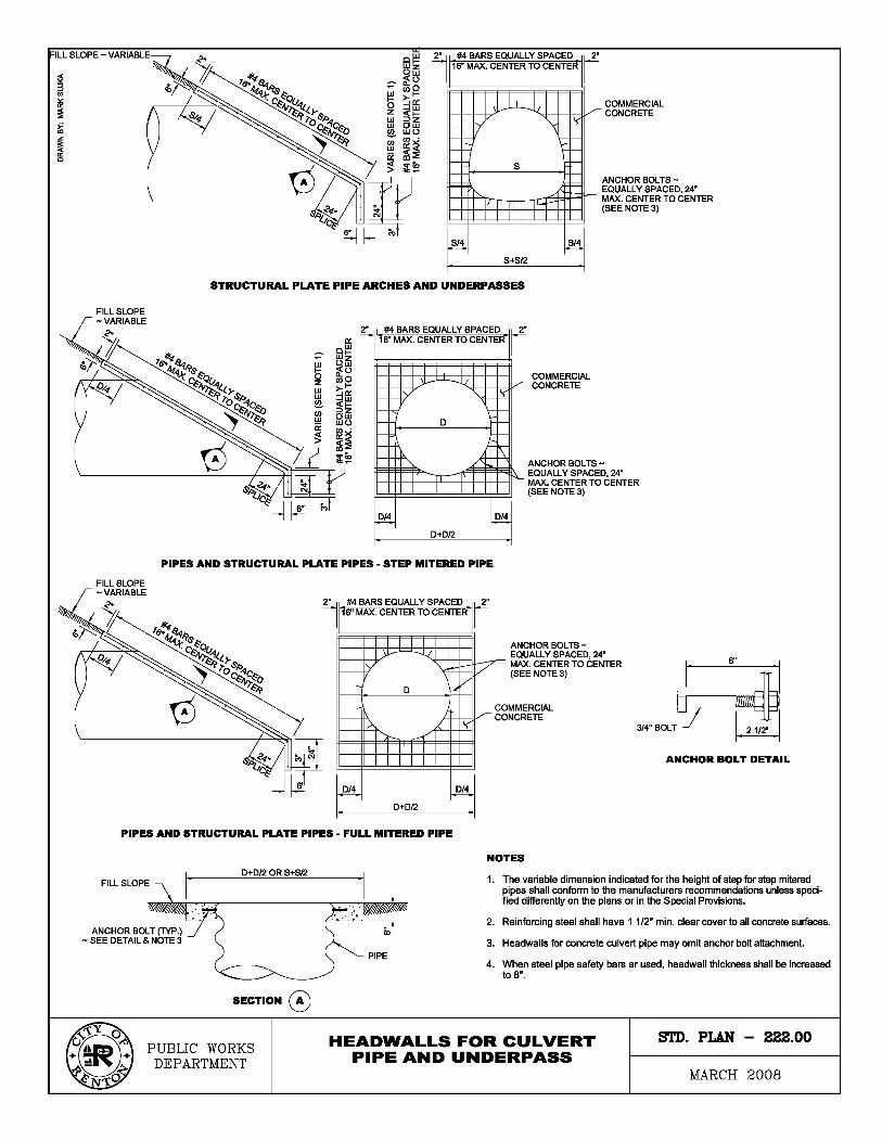
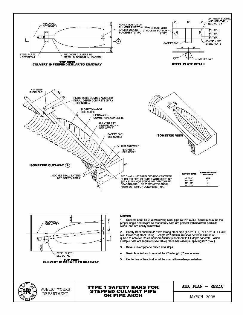
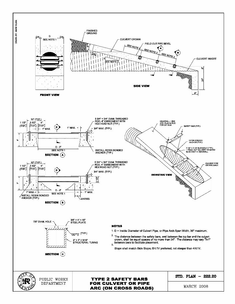
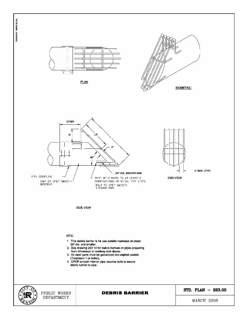
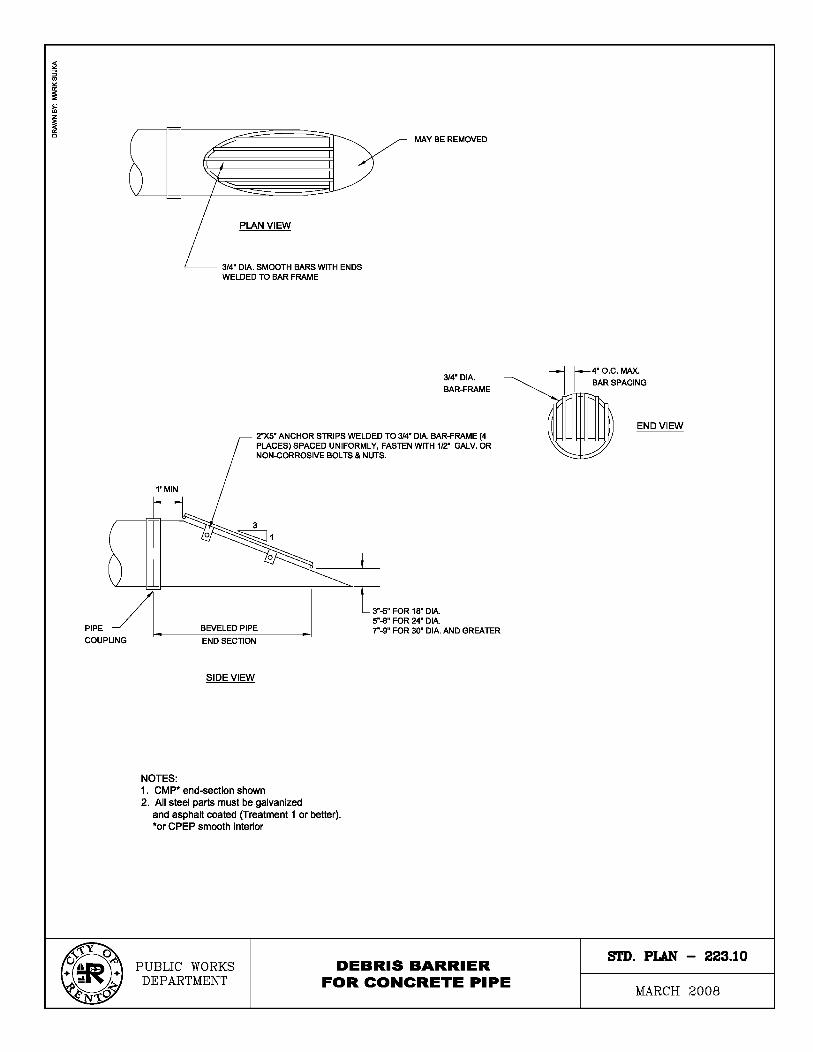
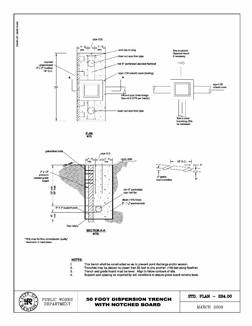
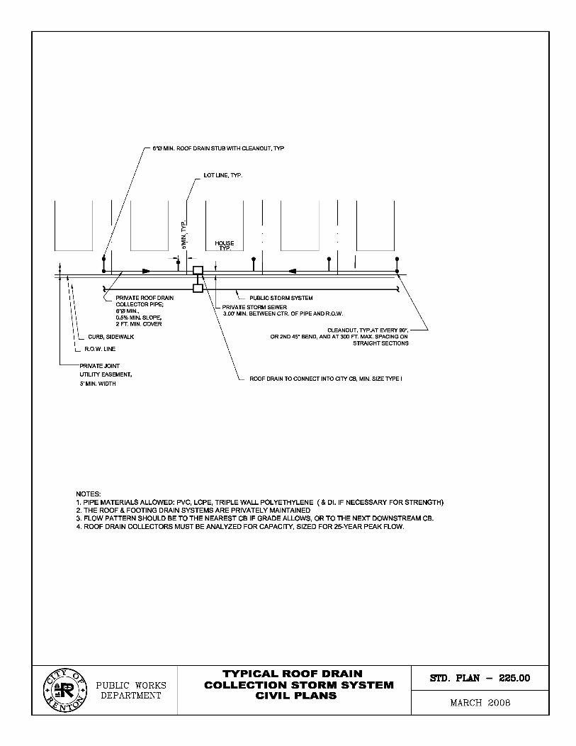
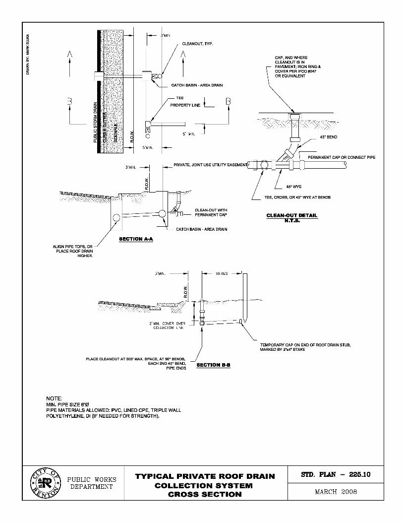
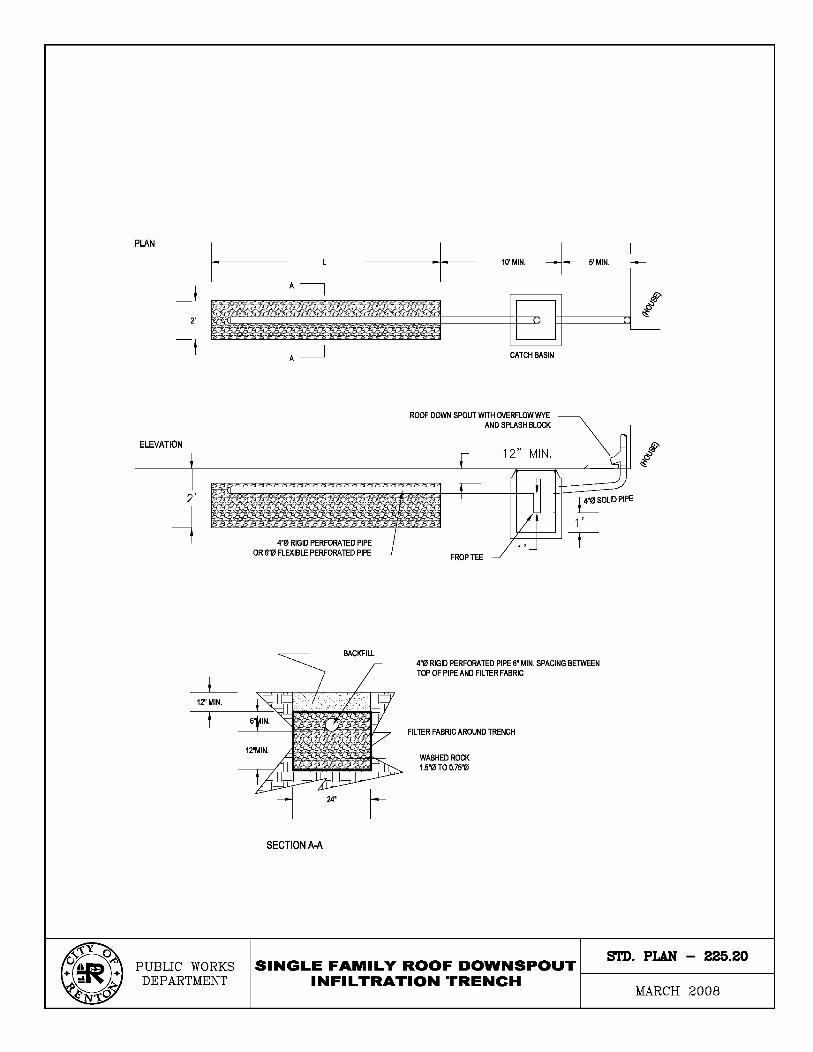
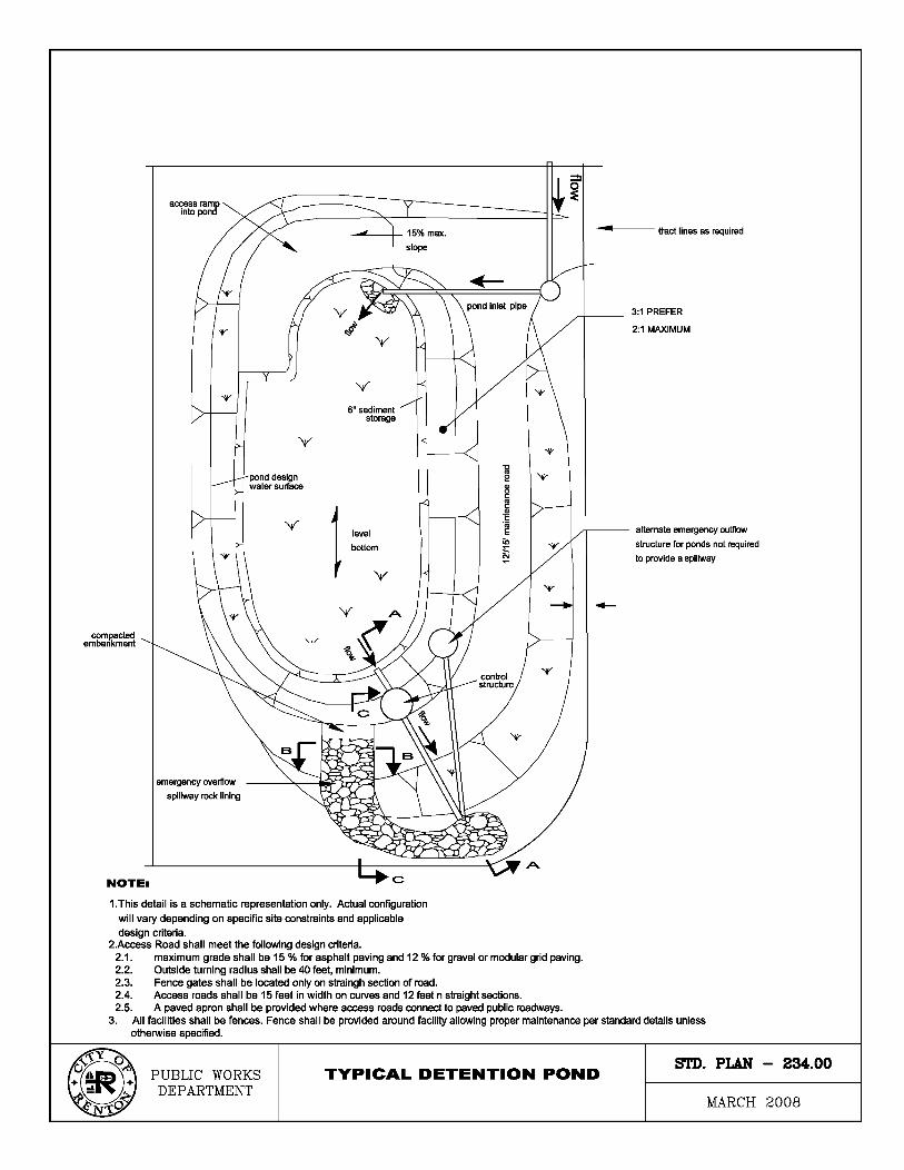


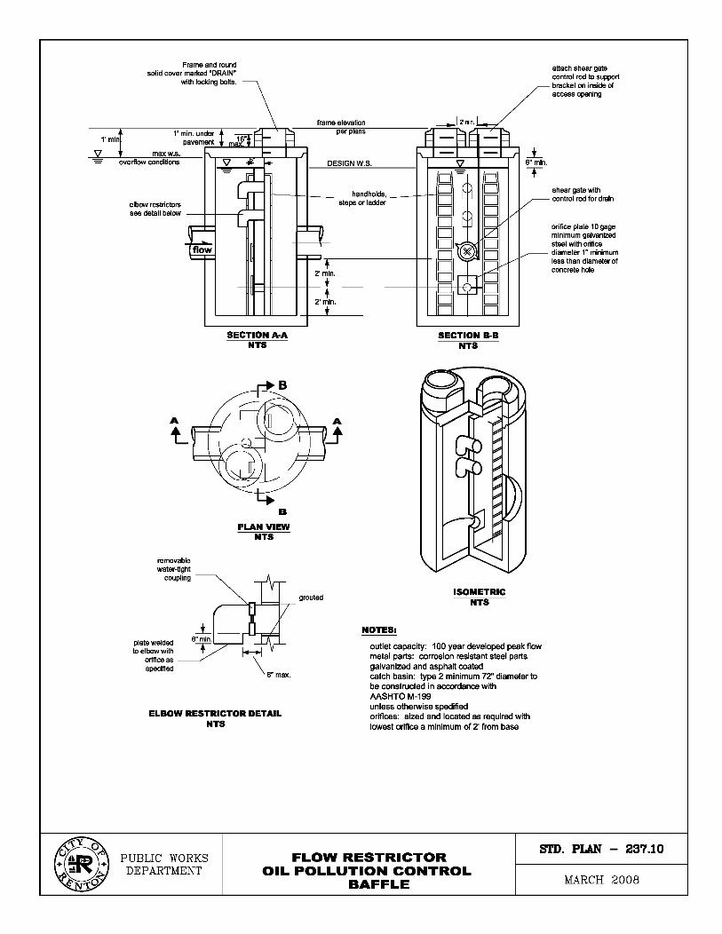
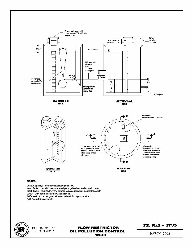
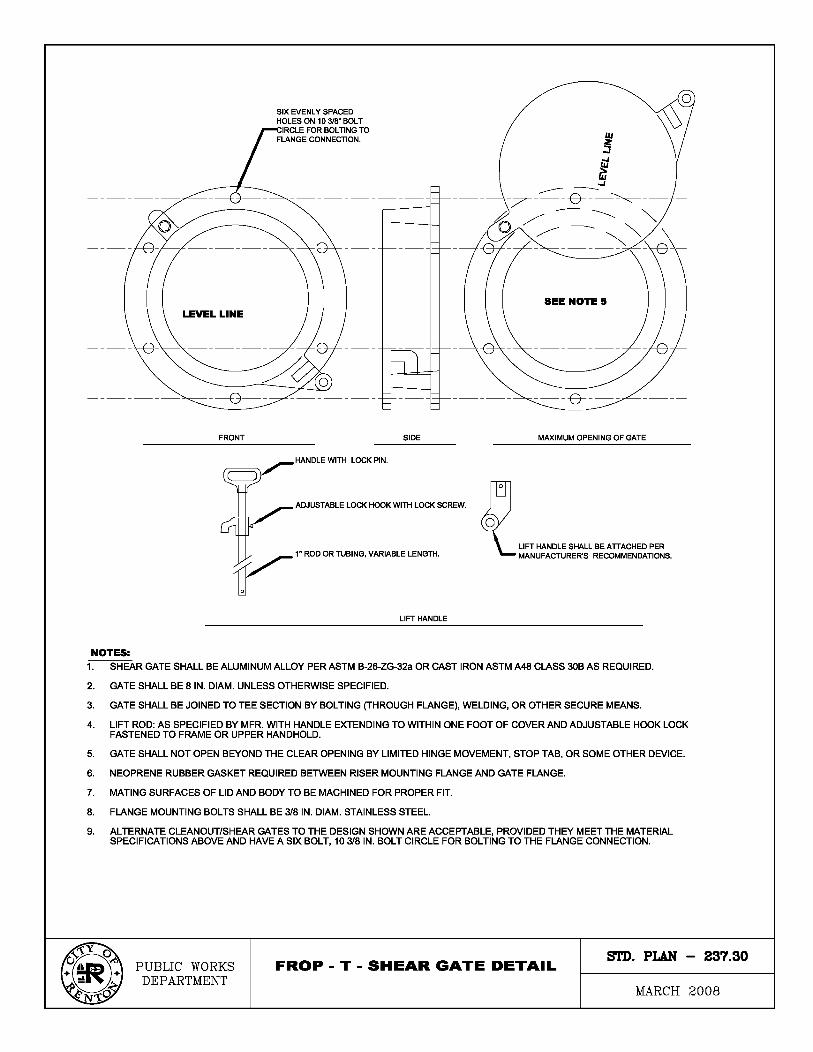

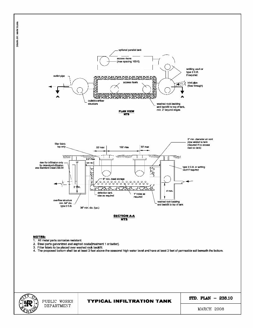
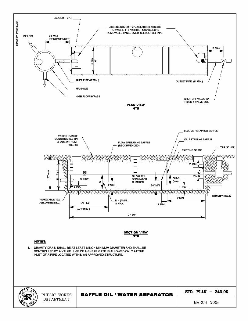
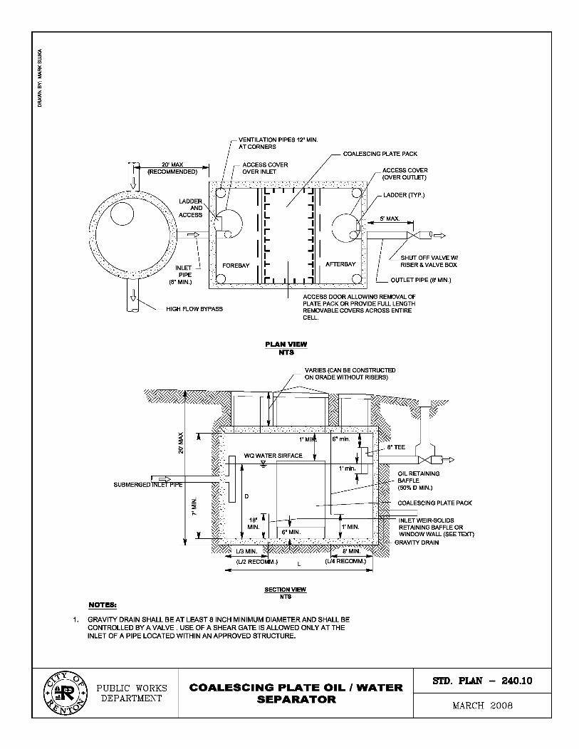
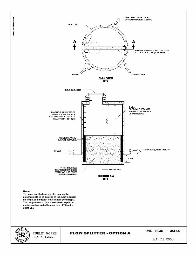
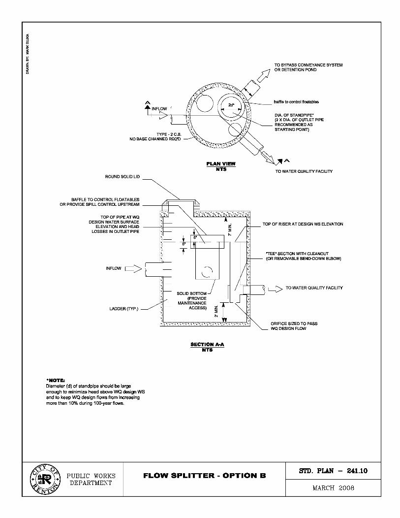
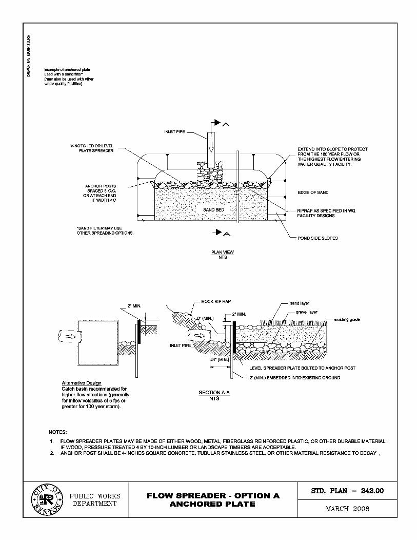
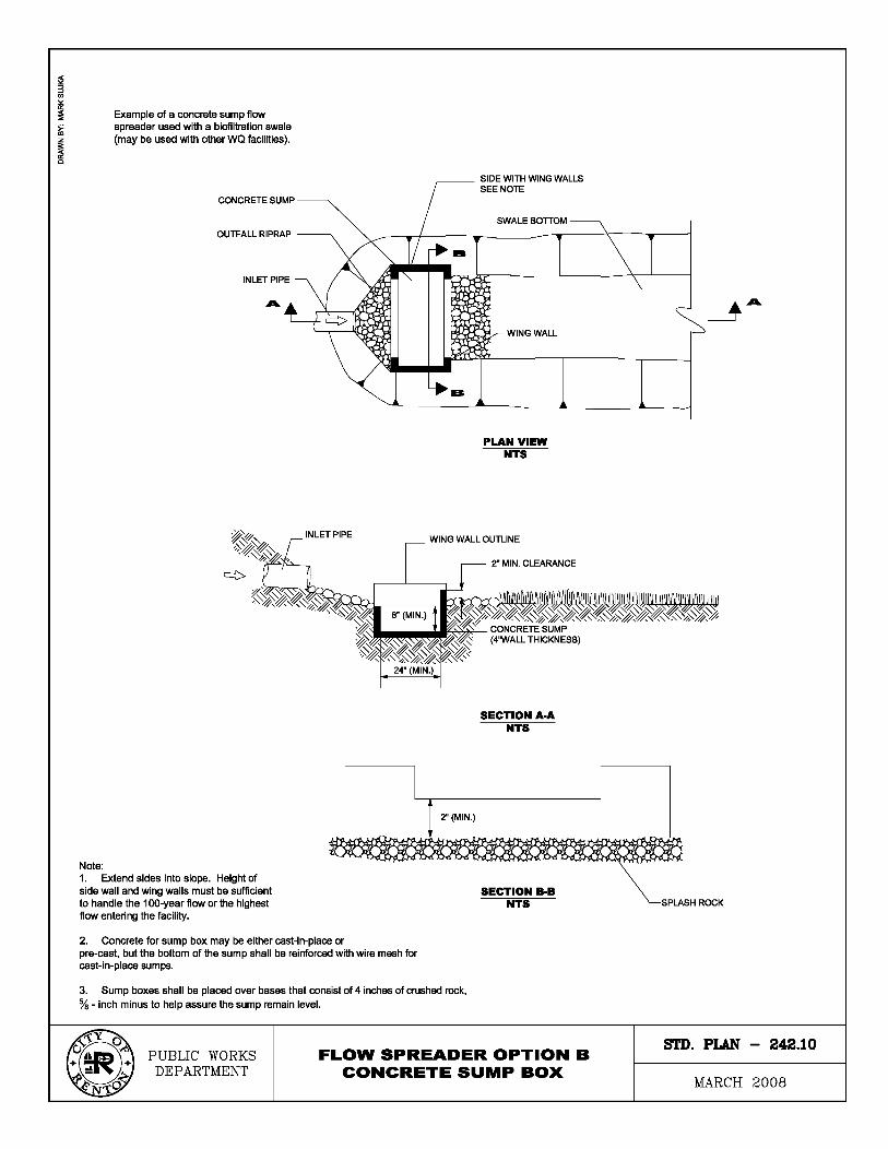
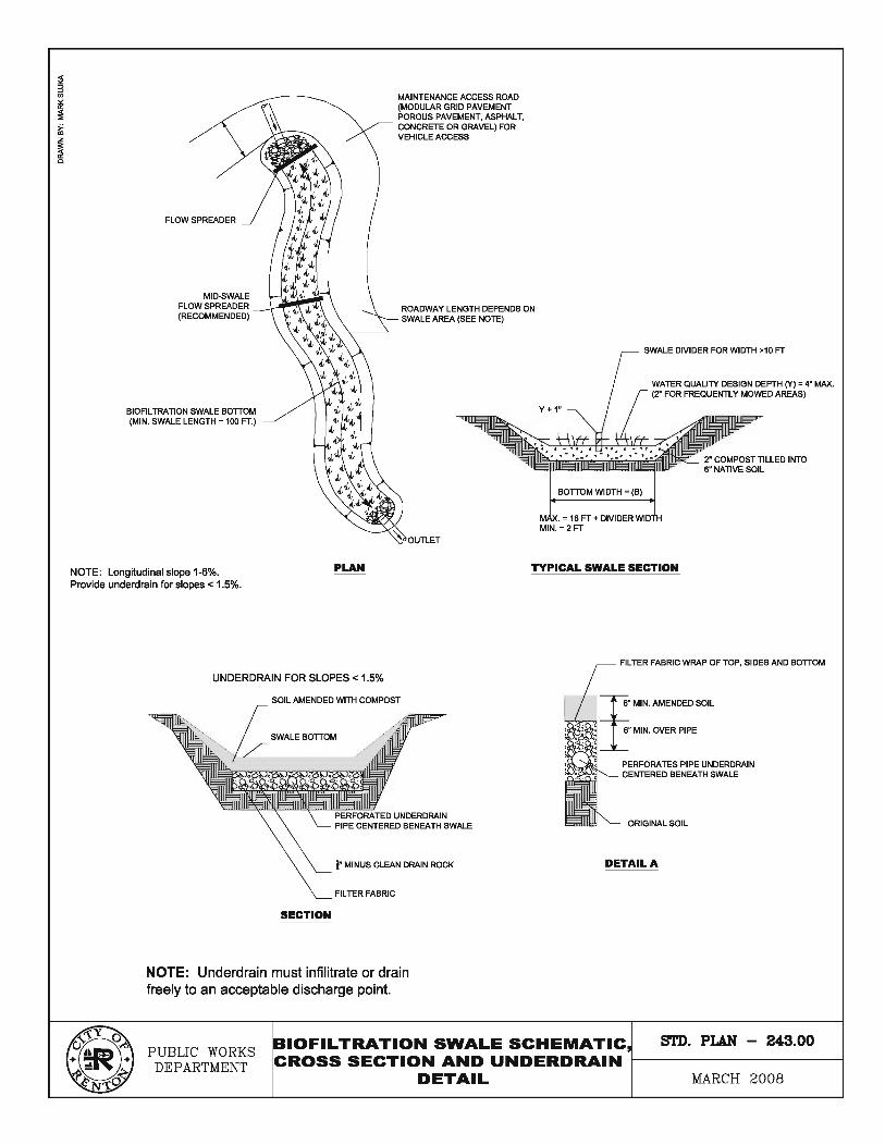
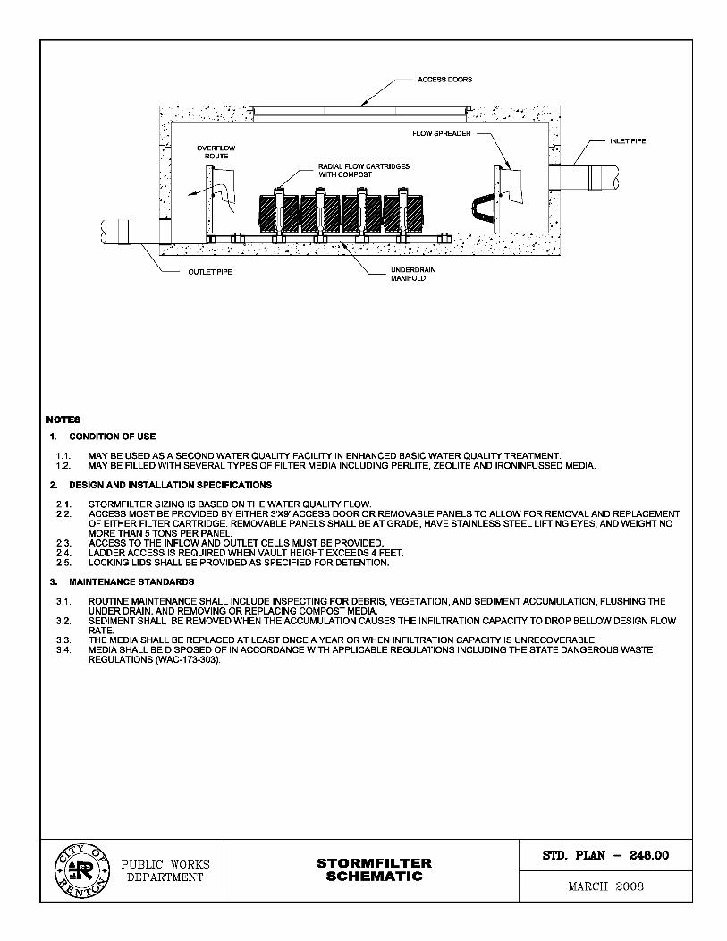
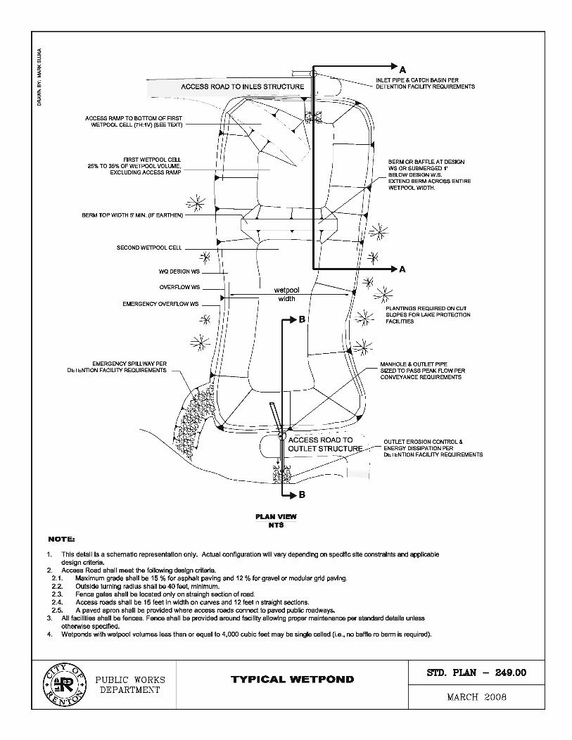
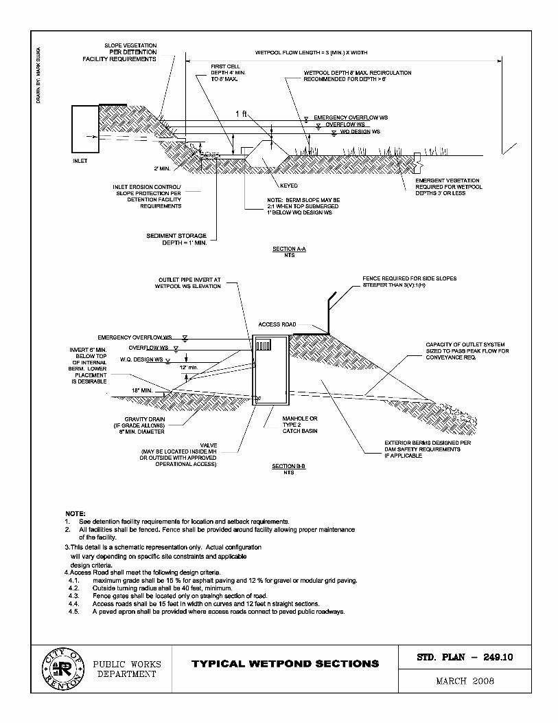

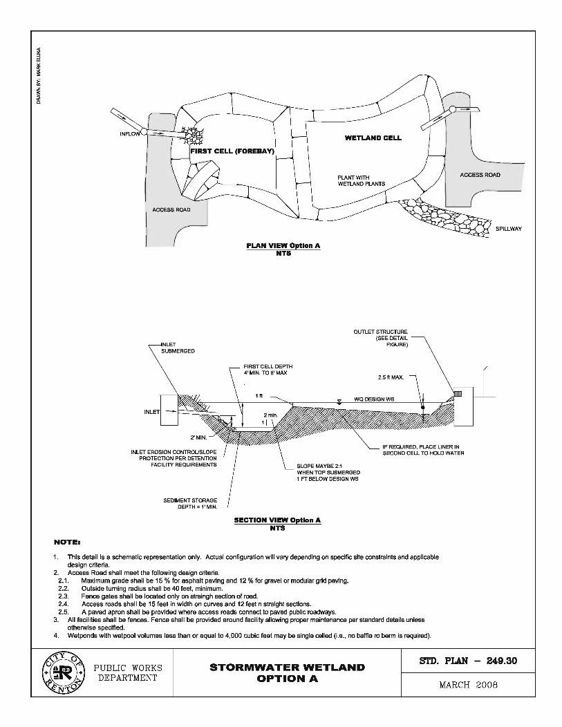
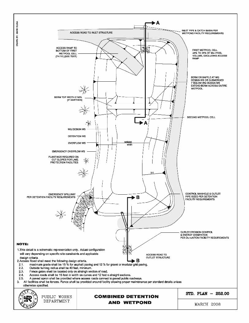
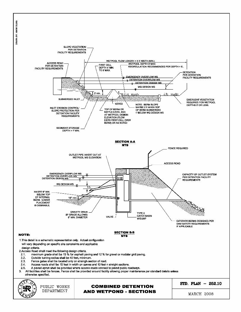
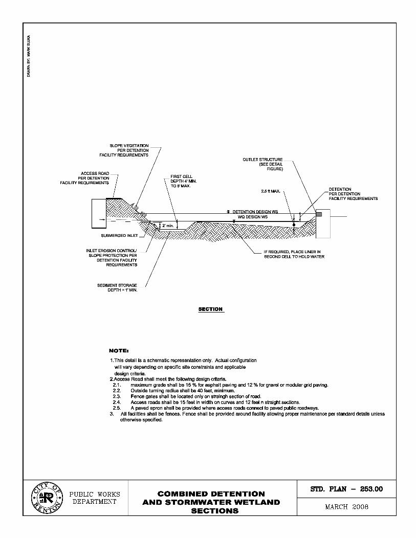
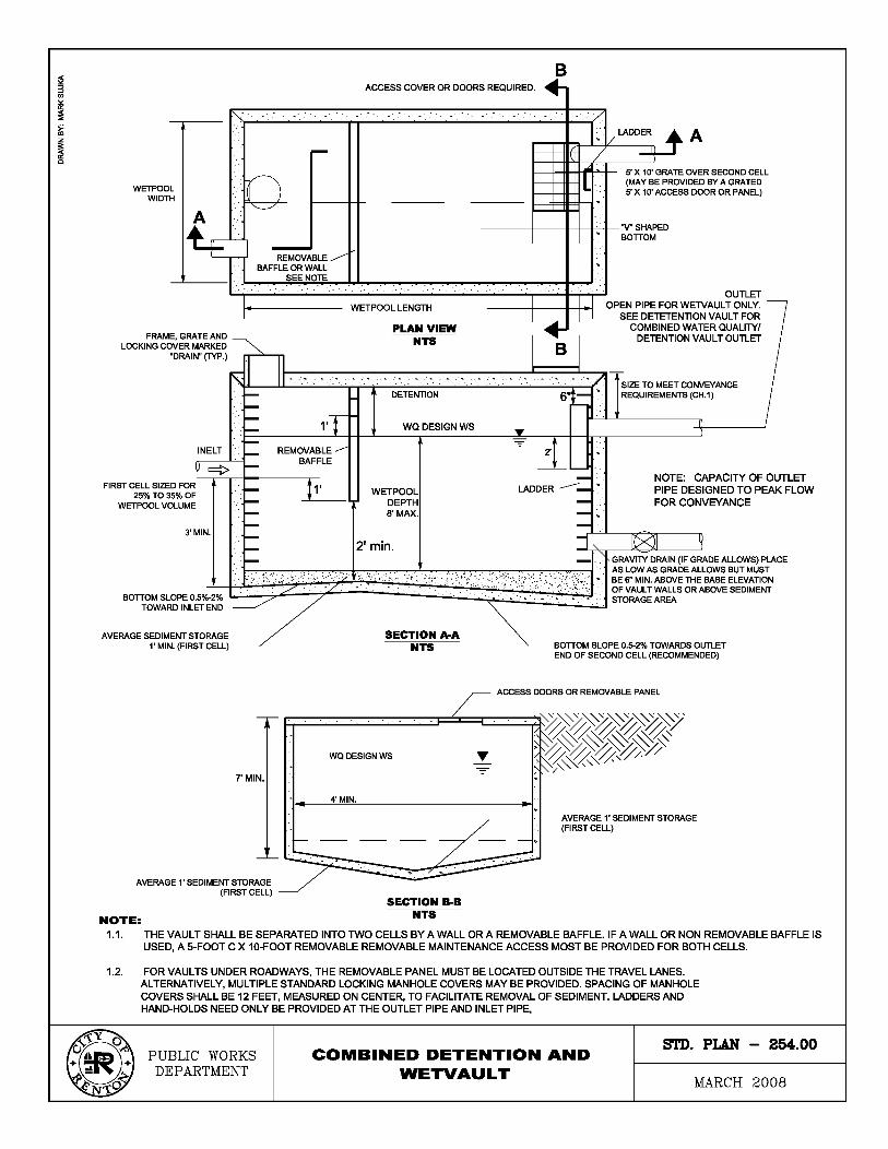
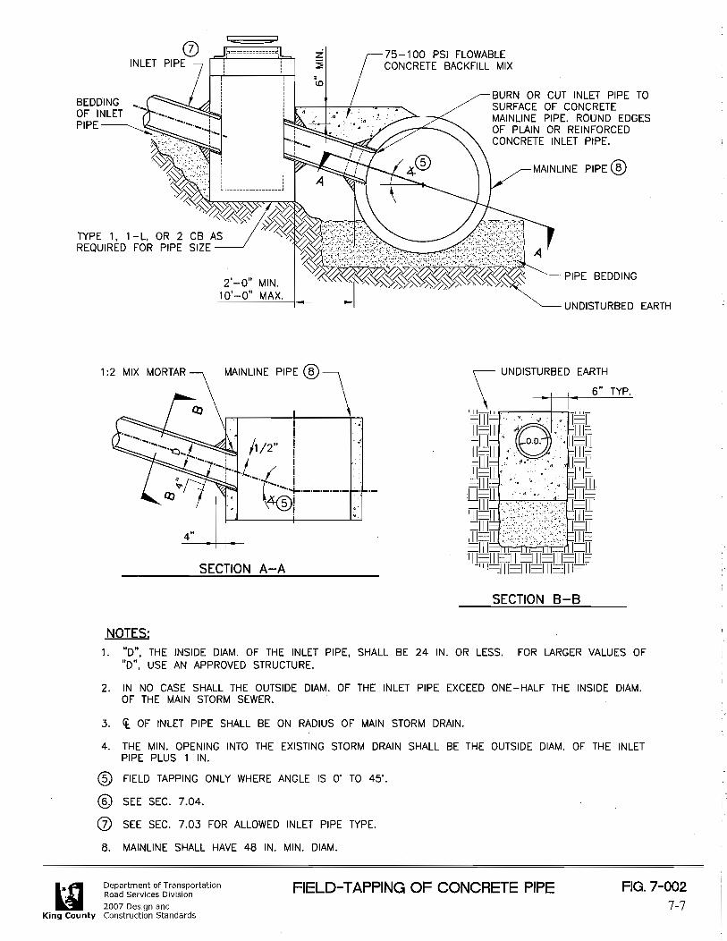
2009 Surface Water Design Manual Amendment City of Renton
REFERENCE
CITY OF RENTON AMENDMENTS TO THE KING COUNTY SURFACE WATER DESIGN MANUAL February 2010
Notes:
This reference section both references some applicable information from the 2009 KCSWDM and includes replacement and/or new reference materials in hard copy in this document. Those incorporated by reference are indicated by an asterisk (*). Those King County references that do not apply are indicated by a cross (†). The City of Renton and King County (by referencing some County documents) assume no responsibility for the completeness or current status of the materials contained in this section. It is the sole responsibility of each applicant to insure that the most current materials are used in preparing a permit application for their proposed project. Copies of these materials are available from the City of Renton or DDES as applicable.
1 Ordinance Adopting Drainage (Surface Water) Standards
2 Adopting Critical Drainage Areas† 3 Other Adopted Area Specific Drainage
Requirements A RA Zone Clearing Restrictions†
4 Other Drainage Related Regulations and Guidelines A Grading Code Soil Amendment Standard† B Clearing & Grading Seasonal Limitations† C Landscape Management Plan Guidelines* D Shared Facility Maintenance Guidance†
5 Wetland Hydrology Protection Guidelines* 6 Hydrologic/Hydraulic Design Methods
A EPA Infiltration Rate Test* B Pond Geometry Equations*
7 Engineering Plan Support A King County Standard Map Symbols* B Surface Water Standard Plan Notes and Example
Construction Sequencing C Stormfilter Access and Cartridge Configuration†
8 Forms and Worksheets A Technical Information Report (TIR) Worksheet* B Offsite Analysis Drainage System Table* C Water Quality Facility Sizing Worksheets* D Flow Control and Water Quality Facility Summary
Sheet and Sketch* E CSWPPP Worksheet Forms* F Adjustment Application and Process Guidelines† G Dedication and Indemnification Clause – Final
Recording† H Bond Quantities Worksheet I Maintenance and Defect Agreement J Drainage Facility Covenant K Drainage Release Covenant L Drainage Easement M Flow Control BMP Covenant N Impervious Surface Limit Covenant O Clearing Limit Covenant P River Protection Easement – King County* P1 River Protection Easement – City of Renton Q Leachable Metals Covenant
9 Interim Changes to Requirements† 10 King County Identified Water Quality Problems† 11 Maps
A Flow Control Application Map B Ground Water Protection Areas C Soil Survey Map
* Incorporated by reference. † King County reference does not apply to City of
Renton.

2009 Surface Water Design Manual Amendment City of Renton
CITY OF RENTON AMENDMENTS TO THE KING COUNTY
SURFACE WATER DESIGN MANUAL
REFERENCE 1 ORDINANCE ADOPTING DRAINAGE (SURFACE WATER) STANDARDS

CITY OF RENTON, WASHINGTON
ORDINANCE NO. 5526
AN ORDINANCE OF THE CITY OF RENTON, WASHINGTON, AMENDING CHAPTER 2, ZONING DISTRICTS - USES AND STANDARDS; CHAPTER 3, ENVIRONMENTAL REGULATIONS AND OVERLAY DISTRICTS; CHAPTER 4, CITY-WIDE PROPERTY DEVELOPMENT REGULATIONS; CHAPTER 6, STREET AND UTILITY STANDARDS; CHAPTER 8, PERMITS - GENERAL AND APPEALS; CHAPTER 9, PERMITS -SPECIFIC; AND CHAPTER 11, DEFINITIONS, OF TITLE IV (DEVELOPMENT REGULATIONS) OF ORDINANCE NO. 4260 ENTITLED "CODE OF GENERAL ORDINANCES OF THE CITY OF RENTON, WASHINGTON" TO AMEND DRAINAGE REGULATIONS AND ADOPT BY REFERENCE PORTIONS OF THE KING COUNTY SURFACE WATER DESIGN MANUAL AND AMENDMENTS THERETO.
THE CITY COUNCIL OF THE CITY OF RENTON, WASHINGTON, DOES ORDAIN AS
FOLLOWS:
SECTION I. The row labeled "R-l" in the Maximum Building Coverage section of
subsection 4-2-110A, Development Standards for Residential Zoning Designations (Primary and
Attached Accessory Structures), of Chapter 2, Zoning Districts - Uses and Standards, of Title IV
(Development Regulations) of Ordinance No. 4260 entitled "Code of General Ordinances of the
City of Renton, Washington", is hereby amended to read as shown on Attachment A.
SECTION II. The Maximum Impervious Surface Area section of subsection 4-2-110A,
Development Standards for Residential Zoning Designations (Primary and Attached Accessory
Structures), of Chapter 2, Zoning Districts - Uses and Standards, of Title IV (Development
Regulations) of Ordinance No. 4260 entitled "Code of General Ordinances of the City of Renton,
Washington", is hereby amended to read as shown on Attachment B.
SECTION III. Subsection 4-3-050C.5.d.ii, New or Modified Regional Stormwater
Facilities, of Chapter 3, Environmental Regulations and Overlay Districts, of Title IV
ORDINANCE NO. 5526
(Development Regulations) of Ordinance No. 4260 entitled "Code of General Ordinances of the
City of Renton, Washington", is hereby amended to read as shown on Attachment C.
SECTION IV. Subsection 4-3-050C.7.a.ii, Stormwater Treatment and Flow Control
Facilities in Buffer, of Chapter 3, Environmental Regulations and Overlay Districts, of Title IV
(Development Regulations) of Ordinance No. 4260 entitled "Code of General Ordinances of the
City of Renton, Washington", is hereby amended to read as shown on Attachment D.
SECTION V. Subsection 4-3-050C.7.a, Activities in Critical Area Buffers, of Chapter 3,
Environmental Regulations and Overlay Districts, of Title IV (Development Regulations) of
Ordinance No. 4260 entitled "Code of General Ordinances of the City of Renton, Washington",
is hereby amended to add a new subsection iii, entitled "Stormwater Conveyance in Buffer", to
read as shown on Attachment E.
SECTION VI. Subsection 4-3-050H.2.d.vi(b), Site Improvements, of Chapter 3,
Environmental Regulations and Overlay Districts, of Title IV (Development Regulations) of
Ordinance No. 4260 entitled "Code of General Ordinances of the City of Renton, Washington",
is hereby amended to read as follows:
(b) Site Improvements:
(1) For facilities located in Zone 1 of an APA, the owner may be required to
pave all currently unpaved areas of their facility that are subject to any vehicular
use or storage, use, handling, or production of hazardous materials.
(2) For those facilities located in Zone 1 of an APA in which the nature of the
business involves the use of hazardous materials outside of fully enclosed
structures, the City shall evaluate the existing storm water collection and
ORDINANCE NO. 5526
conveyance system, and reserves the right to require the owner to upgrade the
system to meet the provisions of RMC 4-6-030E4(f), Special Requirement 6 -
Aquifer Protection Area (APA).
(3) For those facilities located in Zone 1 of an APA, the City may require the
owner to test interior wastewater plumbing and the building side sewer for
tightness according to subsection H6a(ii) of this Section, Pipeline Requirements-
Zone 1, and reserves the right to require that such wastewater conveyance be
repaired or replaced according to subsection H6a(i) of this Section, Pipeline
Requirements-Zone 1.
SECTION VII. Subsection d of subsection 4-3-110E.5, Standards Within Entire Urban
Separator, of Chapter 3, Environmental Regulations and Overlay Districts, of Title IV
(Development Regulations) of Ordinance No. 4260 entitled "Code of General Ordinances of the
City of Renton, Washington", is hereby amended to read as follows:
d. Stormwater management shall comply with the Surface Water Design Manual.
SECTION VIM. Subsection 4-4-030B, Adoption by Reference, of Chapter 4, City-wide
Property Development Standards, of Title IV (Development Regulations) of Ordinance No. 4260
entitled "Code of General Ordinances of the City of Renton, Washington", is hereby amended
to read as follows:
B. ADOPTION BY REFERENCE:
The goals, objectives, and policies as set forth in the following documents
and related studies or documents are presently in force or as modified from time
ORDINANCE NO. 5526
to time are hereby incorporated by reference and shall be considered as if fully
set forth herein:
Cedar River Master Plan
Comprehensive Solid Waste Management Plan
Green River Valley Plan
Fire Department Master Plan
Airport Master Plan
Comprehensive Park, Recreation and Open Space Plan
Comprehensive Water System Plan
Long Range Wastewater Management Plan
King County Comprehensive Housing Affordability Strategy (CHAS)
Shoreline Master Program
King County Solid Waste Management Plan
Countywide Planning Policies
Six-Year Transportation Improvement Plan
Street Arterial Plan
Traffic Mitigation Resolution and Fee
Parks Mitigation Resolution and Fee
Fire Mitigation Resolution and Fee
Comprehensive Plan
SECTION IX. Subsection 4-4-030C.5, Temporary Erosion Control, of Chapter 4, City-
wide Property Development Standards, of Title IV (Development Regulations) of Ordinance No.
ORDINANCE NO. 5526
4260 entitled "Code of General Ordinances of the City of Renton, Washington", is hereby
amended to read as follows:
5. Temporary Erosion Control: Temporary erosion control must be installed
and maintained for the duration of the project. This work must comply with the
Surface Water Design Manual and must be approved by the Renton
Development Services Division.
SECTION X. Subsection 4-4-030C.6, Hydroseeding Required, of Chapter 4, City-wide
Property Development Standards, of Title IV (Development Regulations) of Ordinance No. 4260
entitled "Code of General Ordinances of the City of Renton, Washington", is hereby amended
to read as follows:
6. Hydroseeding Required: Within thirty (30) days of completion of grading
work, the applicant shall hydroseed or plant an appropriate ground cover over
any portion of the site that is graded or cleared of vegetation and where no
further construction work will occur within ninety (90) days. Alternative
measures such as mulch, sodding, or plastic covering as specified in the Surface
Water Design Manual may be proposed between the dates of October 1st and
April 30th of each year. The Development Services Division's approval of this
work is required prior to final inspection and approval of the permit.
SECTION XI. Subsection 4-4-060A, Purpose, of Chapter 4, City-wide Property
Development Standards, of Title IV (Development Regulations) of Ordinance No. 4260 entitled
"Code of General Ordinances of the City of Renton, Washington", is hereby amended to add
two new subsections, 5 and 6, to read as follows:
ORDINANCE NO. 5526
5. Minimize adverse stormwater impacts generated by the removal of
vegetation and alteration of landform in order to comply with the requirements
of the National Pollutant Discharge Elimination System (NPDES) Phase II
Municipal Stormwater Permit.
6. Protect water quality from the adverse impact associated with erosion
and sedimentation in order to comply with the requirements of the National
Pollutant Discharge Elimination System (NPDES) Phase II Municipal Stormwater
Permit.
SECTION XII. Subsection 4-4-060C.4, Hydroseeding Required, of Chapter 4, City-wide
Property Development Standards, of Title IV (Development Regulations) of Ordinance No. 4260
entitled "Code of General Ordinances of the City of Renton, Washington", is hereby amended
to read as follows:
4. Hydroseeding Required: Within thirty (30) days of completion of grading
work, the applicant shall hydroseed or plant an appropriate ground cover over
any portion of the site that is graded or cleared of vegetation and where no
further construction work will occur within ninety (90) days. Alternative
measures such as mulch, sodding, or plastic covering as specified in the Surface
Water Design Manual may be proposed between the dates of October 1st and
April 30th of each year. The Development Services Division's approval of this
work is required prior to final inspection and approval of the permit.
SECTION XIII. Section 4-4-060, Grading, Excavating and Mining Regulations, of Chapter
4, City-wide Property Development Standards, of Title IV (Development Regulations) of
ORDINANCE NO. 5526
Ordinance No. 4260 entitled "Code of General Ordinances of the City of Renton, Washington",
is hereby amended to add a new subsection D, entitled General Erosion and Sediment Control
Standards, to read as shown below. The current subsections D-E shall be re-lettered
accordingly.
D. GENERAL EROSION AND SEDIMENT CONTROL STANDARDS:
1. Erosion and Sediment Control Required: A person who clears, grades or
otherwise disturbs a site shall provide erosion and sediment control that
prevents, to the maximum extent practicable, the transport of sediment from
the site to drainage facilities, water resources and adjacent properties. Erosion
and sediment controls shall be applied as specified by the temporary erosion and
sediment control measures and performance criteria and implementation
requirements in the Surface Water Design Manual adopted in accordance with
RMC 4-6-030.
2. Seasonal Limitations: From October 1 through April 30, which is the
seasonal limitation period, clearing and grading shall only be permitted if shown
to the satisfaction of the Director that runoff leaving the construction site will
comply with the erosion and sediment control measures and performance
criteria and implementation requirements in the Surface Water Design Manual
through a combination of the following:
a. Site conditions including vegetative coverage, slope, soil type and
proximity to receiving waters; and
ORDINANCE NO. 5526
b. Proposed limitations on activities and the extent of disturbed areas;
and
c. Proposed erosion and sedimentation control measures.
3. Expansion or Restriction of Seasonal Limitations: Based on the
information provided under subsection Dl of this section, the Administrator or
designee may expand or restrict the seasonal limitations on site disturbance. The
Administrator or designee shall set forth in writing the basis for approval or
denial of clearing or grading during the seasonal limitation period.
4. Approved Erosion and Sediment Control Plan Required: During the
seasonal limitation period, clearing and grading will be allowed only if there is
installation and maintenance of an erosion and sedimentation control plan
approved by the City of Renton Development Services Division that defines any
limits on clearing and grading or specific erosion and sediment control measures
required during the seasonal limitation period. The Development Services
Division may require or approve alternate best management practices.
5. Violation: If, during the course of construction activity or soil disturbance
during the seasonal limitation period, silt-laden runoff violating standards in the
Surface Water Design Manual leaves the construction site or if clearing and
grading limits or erosion and sediment control measures shown in the approved
plan are not maintained, the department inspector shall have the responsibility
and authority to issue a partial or total stop work order.
ORDINANCE NO. 5526
6. Continued Violation: If the erosion and sediment control problem defined
in the stop work order is not adequately repaired within twenty-four (24) hours
of issuance, then a notice and order may be issued to install adequate erosion
and sediment control measures to stop silt-laden runoff from leaving the site.
The order may also require the property owner to discontinue any further
clearing or grading, except for erosion and sediment control maintenance and
repair, until the following April 30.
SECTION XIV. Subsection 4-4-060E, Inspection, of Chapter 4, City-wide Property
Development Standards, of Title IV (Development Regulations) of Ordinance No. 4260 entitled
"Code of General Ordinances of the City of Renton, Washington", is hereby re-lettered as
subsection F pursuant to Section X of this ordinance, and amended to read as follows:
F. INSPECTION:
1. Inspection Authorized: All operations regulated by this Section shall be
subject to inspection by authorized Development Services Division inspection
personnel. When extraordinary or special problems or conditions are involved,
extra inspection of grading operations and special tests may be ordered by the
City.
2. Entry to be Permitted: No owner or occupant or any other person having
charge, care or control of any building, land, structure, premises or portion
thereof shall fail or neglect, after proper demand, to promptly permit lawful
entry thereon by the Development Services Division inspection personnel for the
purpose of inspection and examination pursuant to this Section.
ORDINANCE NO. 5526
SECTION XV. Section 4-4-060, Grading, Excavating and Mining Regulations, of Chapter
4, City-wide Property Development Standards, of Title IV (Development Regulations) of
Ordinance No. 4260 entitled "Code of General Ordinances of the City of Renton, Washington",
is hereby amended to add a new subsection G, entitled Restoration of Hazard Required, to read
as shown below. The current subsections G-S shall be re-lettered accordingly.
G. RESTORATION OF HAZARD REQUIRED:
Whenever the Administrator or designee determines that an existing site, as
a result of clearing or grading, excavation, embankment, or fill has become a
hazard to life and limb, or endangers property, or adversely affects the safety,
use or stability of a public way or drainage channel, the owner of the property
upon which the clearing, grading, excavation or fill is located, or other person or
agent in control of said property, upon receipt of notice in writing from the
Administrator or designee, shall within the period specified therein restore the
site affected by such clearing or grading or repair or eliminate such excavation or
embankment or fill so as to eliminate the hazard and be in conformance with the
requirements of this chapter.
SECTION XVI. Subsection 4-4-060Q, Permits and Fees, of Chapter 4, City-wide Property
Development Standards, of Title IV (Development Regulations) of Ordinance No. 4260 entitled
"Code of General Ordinances of the City of Renton, Washington", is hereby re-lettered as
subsection S pursuant to Section XII of this ordinance, and amended to change the title to
"Permits and Fees Required" and to read as follows:
10
ORDINANCE NO. 5526
S. PERMITS AND FEES REQUIRED:
1. Submittal Requirements and Fees: Grading, excavation and mining
permits and licenses are required per RMC 4-9-080 for major and minor
activities. Submittal requirements are listed in RMC 4-8-120, Submittal
Requirements - Specific to Application Type. Application fees are listed per
Chapter 4-1 RMC, Administration and Enforcement.
2. Threshold for Drainage Review: A person applying for a grading,
excavation and mining permit and license shall be required to comply with all
drainage review requirements per RMC chapter 4-6-030 if the project results in
seven thousand (7,000) square feet or more of land disturbing activity.
3. Plans and Calculations Required: Submittal of plans and supportive
calculations shall be in accordance with RMC 4-6-030.
SECTION XVII. Section 4-6-030, Drainage (Surface Water) Standards, of Chapter 6,
Street and Utility Standards, of Title IV (Development Regulations) of Ordinance No. 4260
entitled "Code of General Ordinances of the City of Renton, Washington", is hereby amended
to read as follows:
4-6-030 DRAINAGE (SURFACE WATER) STANDARDS:
A. PURPOSE:
1. The purpose of this Section shall be to promote and develop policies with
respect to the City's watercourses and to preserve them by minimizing water
quality degradation by previous siltation, sedimentation and pollution of creeks,
streams, rivers, lakes and other bodies of water, and to protect property owners
11
ORDINANCE NO. 5526
tributary to developed and undeveloped land from increased runoff rates and to
ensure the safety of roads and rights-of-way.
2. It shall also be the purpose of this Section to reduce flooding, erosion, and
sedimentation; prevent and mitigate habitat loss; enhance groundwater
recharge; and prevent water quality degradation through permit review,
construction inspection, enforcement, and maintenance in order to promote the
effectiveness of the requirements.
3. It shall also be a purpose of this Section to regulate the Municipal
Separate Storm Sewer System (MS4) regarding the contribution of pollutants,
consisting of any material other than stormwater, including but not limited to
illicit discharges, illicit connections and/or dumping into any storm drain system,
including surface and/or groundwater throughout the City that would adversely
impact surface and groundwater quality of the City and the State of Washington,
in order to comply with requirements of the National Pollutants Discharge
Elimination System (NPDES) Phase II Municipal Stormwater Permit.
B. ADMINISTERING AND ENFORCING AUTHORITY:
The Administrator of the Public Works Department is responsible for the
general administration and coordination of this Section. All provisions of this
Section shall be enforced by the Administrator or his or her designated
representatives.
12
ORDINANCE NO. 5526
C. ADOPTION OF SURFACE WATER DESIGN MANUAL:
The 2009 King County Surface Water Design Manual (KCSWDM), as now or as
hereafter may be amended by King County or the City of Renton, and hereby
referred to as the Surface Water Design Manual, is hereby adopted by reference,
with the exception of Chapters 1 and 2 of the King County Surface Water Design
Manual which are not adopted. Chapters 1 and 2 of the Surface Water Design
Manual, as amended by the City of Renton to specify local requirements and
procedures, are hereby adopted by reference. References 1, 2, 3, 4A, 4B, 4D, 7B,
7C, 8F, 8G, 9 and 10 of the King County Surface Water Design Manual are not
adopted. One copy of the Surface Water Design Manual shall be filed with the
City Clerk including any amendments thereto.
D. WHEN REQUIRED:
All persons applying for any of the following permits and/or approvals shall
submit for approval a drainage plan with their application and/or request:
1. Mining, excavation or grading permit or license;
2. Shoreline permit;
3. Flood control zone permit;
4. Subdivision;
5. Short plat;
6. Special permit;
7. Temporary permit when involving land disturbance;
8. Building Permit;
13
ORDINANCE NO. 5526
9. Planned urban development;
10. Site plan approval;
11. Construction Permit;
12. Stormwater Permit;
13. Binding Site Plan;
14. Any other development or permit application which will affect the
drainage in any way. The plan submitted during one permit approval process
may be subsequently submitted with further required applications. The plan
shall be supplemented with additional information at the request of the Public
Works Department.
E. DRAINAGE REVIEW:
1. When Required: A drainage review is required when any proposed
project is subject to a City of Renton permit or approval as determined under
Subsection D of this Section and:
a. Would result in two thousand (2,000) square feet or more of new
impervious surface, replace impervious surface or new plus replaced impervious
surface; or
b. Would involve seven thousand (7,000) square feet of land disturbing
activity; or
c. Would construct or modify a drainage pipe or ditch that is twelve
inches (12") or more in size or depth or receives surface or stormwater runoff
14
ORDINANCE NO. 5526
from a drainage pipe or ditch that is twelve inches (12") or more in size or depth;
or
d. Contains or is adjacent to a critical area designation, defined and
regulated in RMC 4-3-050.
2. Scope of Review: The drainage review for any proposed project shall be
scaled to the scope of the project's size, type of development and potential for
impacts to the regional surface water system to facilitate preparation and review
of project applications. If drainage review for a proposed project is required
under Subsection E of this Section, the Renton Development Services Division
shall determine which of the following drainage reviews apply as specified in the
Surface Water Design Manual:
a. Small project drainage review;
b. Targeted drainage review;
c. Full drainage review;
d. Large project drainage review.
3. Core Requirements: A proposed project required to have drainage review
by Subsection El of this Section must meet each of the following core
requirements which are described in detail in the Surface Water Design Manual.
Projects subject only to small project drainage review that meet the small
project drainage requirements specified in the Surface Water Design Manual,
including flow control best management practices, erosion and sediment control
15
ORDINANCE NO. 5526
measures, and drainage plan submittal requirements are deemed to comply with
the following core requirements:
a. Core requirement 1 - Discharge at the natural location: All surface and
storm water runoff from a project shall be discharged at the natural location so
as not to be diverted onto, or away from, downstream properties. The manner in
which runoff is discharged from the project site shall not create a significant
adverse impact to downhill properties or drainage systems as specified in the
discharge requirements of the Surface Water Design Manual.
b. Core requirement 2 - Offsite analysis: The initial application submittal
for proposed projects shall include an offsite analysis report that assesses
potential offsite drainage impacts associated with development of the proposed
site and proposes appropriate mitigations to those impacts. This initial submittal
shall include, at minimum, a Level One downstream analysis as described in the
Surface Water Design Manual. If impacts are identified, the proposed projects
shall meet any applicable problem-specific requirements as specified in the
Surface Water Design Manual.
c. Core Requirement 3 - Flow control: Proposed projects including
redevelopment projects that would result in two thousand (2,000) square feet or
more of new plus replaced impervious surface or thirty-five thousand (35,000)
square feet or more of new pervious surface, shall provide flow control facilities
or flow control BMPs, or both, to control surface and storm water runoff
generated by new impervious surface, new pervious surface, and replaced
16
ORDINANCE NO. 5 5 2 6
impervious surface, as specified in the Surface Water Design Manual. Flow
control facilities shall meet the area-specific flow control facility requirements
and in accordance with the applicable flow control facility implementation
requirements as specified in the Surface Water Design Manual. Flow control
BMPs shall also be applied as specified in the Surface Water Design Manual.
Projects subject to area-specific flow control facility requirements as shown in
Reference 11-A of the Surface Water Design Manual shall meet one of the
following flow control facility performance criteria as directed in the Surface
Water Design Manual:
i. Peak Rate Flow Control Standard: Shall match the predeveloped
site's peak discharge rates for the two year, ten year and one hundred year
return periods assuming existing site conditions as the predeveloped site
condition;
ii. Flow Control Duration Standard (for existing site conditions): Shall
match the predeveloped site's discharge duration for the discharge rates
between fifty percent (50%) of the two year peak flow through the fifty year
peak flow and the two and ten year peak discharge assuming existing site
conditions as the predeveloped site condition;
iii. Flow Control Duration Standard (for forested site conditions):
Shall match the predeveloped site's discharge duration for the discharge rates
between fifty percent (50%) of the two year peak flow through the fifty year
17
ORDINANCE NO. 5526
peak flow and the two and ten year peak discharge assuming forested site
conditions as the predeveloped site condition.
iv. Flood Problem Flow Control Standard: Shall meet the flow control
duration standard in number iii above and also match the predeveloped site's
discharge rate for the hundred-year return period.
d. Core requirement 4 - Conveyance system: All engineered conveyance
system elements for proposed projects shall be analyzed, designed and
constructed to provide the minimum level of protection against overtopping,
flooding, erosion and structural failure as specified by the conveyance
requirements for new and existing systems and conveyance implementation
requirements described in the Surface Water Design Manual.
e. Core requirement 5 - Erosion and sediment control: All proposed
projects that will clear, grade or otherwise disturb the site shall provide erosion
and sediment control that prevents, to the maximum extent practicable, the
transport of sediment from the site to drainage facilities, water resources and
adjacent properties. Erosion and sediment controls shall be applied in
accordance with RMC 4-4-060 and RMC 4-4-130 as specified by the temporary
erosion and sediment control measures and performance criteria and
implementation requirements in the Surface Water Design Manual.
f. Core requirement 6 - Maintenance and operation: Maintenance of all
drainage facilities in compliance with City of Renton Maintenance Standards is
18
ORDINANCE NO. 5526
the responsibility of property owner as described in the Surface Water Design
Manual.
g. Core requirement 7 - Financial guarantees and liability: All drainage
facilities constructed or modified for projects, except downspout infiltration and
dispersion systems for single family residential lots, must comply with the
liability requirements of RMC 4-6-030M.
h. Core requirement 8 - Water quality: Proposed projects that would
result in five thousand (5,000) square feet or more of new pollution generating
impervious surface or thirty-five thousand (35,000) square feet or more of new
pollution-generating pervious surface, or that are redevelopment projects that
would result in a total of five thousand (5,000) square feet or more of new and
replaced pollution-generating impervious surface, shall provide water quality
treatment facilities to treat polluted surface and storm water runoff generated
by new or replaced pollution-generating impervious surface, as specified in the
Surface Water Design Manual. Water quality treatment facilities shall meet the
land-use water quality treatment requirements and the water quality
implementation requirements applicable to the project site as specified in the
Surface Water Design Manual. The facilities specified by these requirements are
designed to reduce pollutant loads according to the applicable annual average
performance goals listed in Subsections h.i and h.ii of this Section for ninety-five
percent (95%) of the annual average runoff volume:
19
ORDINANCE NO. 5526
i. for basic water quality: remove eighty percent (80%) of the total
suspended solids;
ii. for enhanced basic water quality: remove fifty percent (50%) of
the total zinc.
4. Special Requirements: A proposed project required by Subsection E of
this Section to have drainage review shall meet any of the following special
requirements which apply to the site and which are described in detail in the
Surface Water Design Manual. The City of Renton Development Services Division
shall verify if a proposed project is subject to and must meet any of the following
special requirements:
a. Special Requirement 1 - Other area specific requirements: The
Surface Water Utility may apply a more restrictive requirement for controlling
drainage on an area-specific basis. Other adopted area-specific regulations may
include requirements that have a direct bearing on the drainage design of a
proposed project.
b. Special Requirement 2 - Flood hazard delineation: If a proposed
project contains or is adjacent to a stream, lake, wetland or closed depression, or
if other City regulations require study of flood hazards relating to the proposed
project, the one hundred year floodplain boundaries and floodway shall be
determined and delineated on the site improvement plans and profiles and any
final maps prepared for the proposed project. The flood hazard study shall be
prepared for as specified in the Surface Water Design Manual.
20
ORDINANCE NO. 5526
c. Special Requirement 3 - Flood protection facilities: If a proposed
project contains or is adjacent to a stream that has an existing flood protection
facility, such as a levee, revetment or berm, or proposes to either construct a
new or modify an existing flood protection facility, then the flood protection
facilities shall be analyzed and designed as specified in the Surface Water Design
Manual to conform with the Federal Emergency Management Agency
regulations as found in 44 C.F.R.
d. Special Requirement 4: All commercial, industrial and multifamily
projects (irrespective of size) undergoing drainage review are required to
implement applicable source control in accordance with the King County
Stormwater Pollution Prevention Manual and the Surface Water Design Manual.
e. Special Requirement 5 - Oil control: If a proposed project is a high-
use site, then oil control shall be applied to all runoff from the high-use portion
of the site as specified in the Surface Water Design Manual.
f. Special Requirement 6 - Aquifer Protection Area (APA): If a proposed
project is located within the APA as identified in RMC 4-3-050, then the project
must comply with drainage requirements in the Surface Water Design Manual
and RMC 4-3-050.
F. REQUIREMENTS FOR DRAINAGE REVIEW:
All persons applying for drainage review as specified in Subsection El of this
Section shall submit to the Development Services Division all engineering plans
for review in accordance with the Surface Water Design Manual. The drainage
21
ORDINANCE NO. 5526
plan and supportive calculation report(s) shall be stamped by a professional civil
engineer registered and licensed in the State of Washington.
G. ADOPTION OF STORMWATER POLLUTION PREVENTION MANUAL
(SPPM):
The 2009 King County Stormwater Pollution Prevention Manual (SPPM), as
now or as hereafter may be amended by King County or the City of Renton, and
hereby referred to as the Stormwater Pollution Prevention Manual, is hereby
adopted by reference. One copy of the manual shall be filed with the City Clerk
including any amendments thereto.
H. DISCHARGE PROHIBITION:
1. Prohibition of Illicit Discharge: Materials, whether or not solids or liquids,
other than surface water and stormwater shall not be spilled, leaked, emitted,
discharged, disposed or allowed to escape into the storm sewer and/or drain
system, surface water, groundwater, or watercourses.
a. Examples of illicit discharge include but are not limited to the
following:
i. Trash, debris or garbage;
ii. Construction materials or wastewater;
iii. Petroleum products, including but not limited to oil, gasoline,
greases, fuel oil or heating oil;
iv. Antifreeze, brake fluid, windshield cleaner and other automotive
products;
22
ORDINANCE NO. 5526
v. Metals in either particulate or dissolved form;
vi. Flammable or explosive materials or substances;
vii. Radioactive materials;
viii. Acids or batteries of any kind;
ix. Alkalis or bases;
x. Paints, stains, resins, lacquers, or varnishes;
xi. Degreasers, solvents or chemicals used in laundries or dry
cleaners;
xii. Drain cleaners;
xiii. Pesticides, herbicides and fertilizers;
xiv. Steam cleaning wastes;
xv. Soaps, detergents, ammonias;
xvi. Swimming pool and spa cleaning wastewater and filter backwash
containing water disinfectants (chlorine, bromine, or other chemicals);
xvii. Heated water;
xviii. Domestic animal waste;
xix. Sewage;
xx. Recreational vehicle wastewater or sewage;
xxi. Animal carcasses;
xxii. Food waste;
xxiii. Bark and other fibrous material;
23
ORDINANCE NO. 5526
xxiv. Collected lawn clippings, leaves, branches or other yard waste
material;
xxv. Silt, sediment or gravel;
xxvi. Dyes;
xxvii. Chemicals not normally found in uncontaminated water;
xxviii. Wastewater or process water (including filtered or purified);
xxix. Any pollution or contaminant as referenced in the Stormwater
Pollution Prevention Manual; and
xxx. Any hazardous material as defined in RMC 4-11-080, or waste
not listed above and any other process-associated discharge except as otherwise
allowed in this Section.
b. The following are examples of allowed discharges by this Section if
the discharges do not contain pollutants and unless the Administrator evaluates
and determines that they are causing an adverse impact:
i. Diverted stream flows;
ii. Spring water;
iii. Rising groundwater;
iv. Uncontaminated groundwater infiltration;
v. Uncontaminated pumped groundwater;
vi. Foundation or footing drains;
vii. Water from crawl space pumps;
viii. Air conditioning condensation;
24
ORDINANCE NO. 5 5 2 6
ix. Flows from riparian habitat and wetland;
x. Discharges from emergency fire fighting activities;
xi. Discharges specified in writing by the authorized enforcement
agency as being necessary to protect public health and safety;
xii. Irrigation water from an agricultural source that is commingled
with stormwater runoff;
xiii. Storm system dye testing is allowable by the City, and any dye
testing by others requires verbal notification to the Public Works Department at
least one day prior to the date of the test.
c. Activities that may result in illicit discharge, unless the application of
Best Management Practices (BMPs) as specified in the Stormwater Pollution
Prevention Manual are utilized, include but are not limited to:
i. Discharges from potable water sources, including water line
flushing, hyperchlorinated water line flushing, fire hydrant system flushing, and
pipeline hydrostatic test water. Planned discharges shall be dechlorinated to a
concentration of 0.1 ppm or less, pH-adjusted, if necessary, and volumetrically
and velocity controlled to prevent resuspension of sediments into the MS4;
ii. Discharges from lawn watering and other irrigation runoff. These
shall be minimized through, at a minimum, public education activities and water
conservation efforts;
iii. Dust control with potable water;
iv. Automotive, airplane and boat washing;
25
ORDINANCE NO. 5526
v. Pavement and building washing;
vi. Dechlorinated swimming pool discharges. The discharges shall be
dechlorinated to a concentration of 0.1 ppm or less, pH-adjusted and
reoxygenized if necessary, volumetrically and velocity controlled to prevent
resuspension of sediments in the MS4;
vii. Auto repair and maintenance;
viii. Building repair and maintenance;
ix. Landscape maintenance;
x. Hazardous waste handling;
xi. Solid and food waste handling;
xii. Application of pesticides;
xiii.Non-stormwater discharge permitted under another NPDES
permit; provided that the discharge is in full compliance with all requirements of
the permit, waiver, or other applicable requirements and regulations,
d. A person does not violate this subsection G if:
i. That person has properly designed, constructed, implemented
and is maintaining BMPs as required by this Chapter and Section, but
contaminants continue to enter surface and stormwater and underground
water;
ii. That person can demonstrate that there are no additional
contaminants in discharges from the site above the background conditions of
water entering the site;
26
ORDINANCE NO. 5526
iii. The discharge is a result of an emergency response activity or
other action that must be undertaken immediately or within a time too short to
allow full compliance with this Chapter or Section in order to avoid an imminent
threat to public health or safety. The Administrator by public rule may specify
actions that qualify for this exemption in City procedures. A person undertaking
emergency response activities shall take steps to assure that the discharges
resulting from such activities are minimized. In addition, this person shall
evaluate BMPs to restrict recurrence.
e. Any person who knowingly allows or permits any prohibited
discharges, as set forth in this subsection G or the Stormwater Pollution
Prevention Manual, through illicit connections, dumping, spills, improper
maintenance of BMPs or other discharges, that allow contaminants to enter
surface and stormwater or groundwater, shall be in violation of this Section.
2. Prohibition of Illicit Connections: The construction, use, maintenance or
continued existence of any connection identified by the Administrator or
designee, that may convey any pollution or contaminants or anything not
composed entirely of surface water and stormwater, directly into the MS4, is
prohibited, including without limitation, existing illicit connections regardless of
whether the connection was permissible under law or practices applicable or
prevailing at the time of connection.
3. Remedy:
27
ORDINANCE NO. 5526
a. The person and/or property owner responsible for an illicit
connection and/or illicit discharge shall initiate and complete all actions
necessary to remedy the effects of such connection or discharge at no cost to
the City.
b. If the person responsible for an illicit connection or illicit discharge
and/or the owner of the property on which the illicit connection or illicit
discharge has occurred fails to address the illicit connection or illicit discharge in
a timely manner, the Administrator or designee shall have the authority to
implement removal or remedial actions following lawful entry upon the
property. Such actions may include, but not be limited to: installation of
monitoring wells; collection and laboratory testing of water, soil, and waste
samples; cleanup and disposal of the illicit discharge, and remediation of soil
and/or groundwater. The property owner and/or other person responsible for
the release of an illicit discharge shall be responsible for any costs incurred by
the Public Works Department or its authorized agents in the conduct of such
remedial actions and shall be responsible for City expenses incurred due to the
illicit connection or illicit discharge, including but not limited to removal and/or
remedial actions in accordance with RMC 1-3-3.
c. Compliance with this subsection G shall be achieved through the
implementation and maintenance of best management practices (BMPs)
described in the Stormwater Pollution Prevention Manual. The Administrator or
designee shall initially rely on education and informational assistance to gain
28

ORDINANCE NO. 5 5 2 6
compliance with this subsection G, unless the Administrator or designee
determines a violation poses a hazard to public health, safety, or welfare,
endangers any property and/or other property owned or maintained by the City,
and therefore should be addressed through immediate penalties. The
Administrator or designee may demand immediate cessation of illicit discharges
and assess penalties for violations that are an imminent or substantial danger to
the health or welfare of persons or danger to the environment.
4. Elimination of Illicit Connection and/or Illicit Discharge:
a. Notice of Violation: Whenever the Administrator or designee finds
that a person has violated a prohibition or failed to meet a requirement of this
Section, he or she may order compliance by written notice of violation to the
property owner and/or responsible person, by first class and certified mail with
return receipt requested. Such notice may require without limitation:
i. The performance of monitoring, analyses, and reporting by the
violator;
ii. The elimination of illicit connections or discharges;
iii. That violating discharges, practices, or operations shall
immediately cease and desist;
iv. The abatement or remediation of stormwater pollution or
contamination hazards and the restoration of any affected property; and
v. The implementation of source control or treatment BMPs. Any
person responsible for a property or premises which is, or may be, the source of
29

ORDINANCE NO. 5526
an illicit discharge, may be required to implement, at said person's expense,
additional structural and nonstructural BMPs to prevent the further discharge of
pollutants to the municipal separate storm sewer system and/or waters of the
State. These BMPs shall be part of a stormwater pollution prevention plan
(SWPP) as necessary for compliance with requirements of the NPDES permit.
b. Requirement to Eliminate Illicit Connection: The Administrator or
designee shall send a written notice, sent by first class and certified mail with
return receipt requested to the property owner and/or the person responsible
for the illicit connection, informing the property owner or person responsible for
an illicit connection to the MS4 that the connection must be terminated by a
specified date.
c. Requirement to Eliminate Illicit Discharges: The Administrator or
designee shall send a written notice, sent by first class and certified mail with
return receipt requested to the property owner and/or the person responsible
for the illicit discharge, informing the property owner or person responsible for
an illicit discharge to the MS4, whether it be surface water and/or groundwater,
that the discharge must be terminated by a specified date.
d. Sample and Analysis: When the Administrator or designee has reason
to believe that an illicit connection is resulting in an illicit discharge, the
Administrator or designee may sample and analyze the discharge and recover
the cost of such sampling and analysis from the property owner or person
responsible for such illicit connection or discharge pursuant to RMC 1-3-3, as
30
ORDINANCE NO. 5526
now or as hereafter may be amended, and require the person permitting or
maintaining the illicit connection and/or discharge to conduct ongoing
monitoring at that person's expense.
e. Right of Appeal from Administrative Decision: Any person aggrieved
by an administrative decision of the Administrator or designee, may appeal such
decision pursuant to RMC 4-8-110.
f. Any illicit connection and/or illicit discharge as set forth in this Section
or the Stormwater Pollution Prevention Manual is hereby declared to be a
nuisance pursuant to RMC 1-3-3, and as defined in RMC l-3-4A.ll.c(23).
5. Reporting Requirements:
a. In the event of an illicit discharge or spill of hazardous material into
the stormwater drainage system or waters of the City, State of Washington or
United States, said person with knowledge thereof shall immediately notify the
emergency dispatch services (911).
b. In the event of an illicit discharge of nonhazardous material into the
stormwater drainage system or waters of the City, State of Washington or
United States, said person with knowledge thereof shall immediately notify the
Public Works Department by phone at 425-430-7400, or in person.
6. Inspections, Investigation and Sampling: The Administrator or designee
may lawfully enter property to inspect the facilities of any person to determine
compliance with the requirements of these regulations.
a. Access:
31
ORDINANCE NO. 5526
i. The Administrator or shall be permitted to lawfully enter and
inspect sites subject to regulation under this Chapter and Section as often as
may be necessary to determine compliance herewith, at all reasonable hours for
the purpose of inspections, sampling or records examination.
ii. The Administrator or designee shall have the right to set up on
the property necessary devices to conduct sampling, inspection, compliance
monitoring, and/or metering actions.
b. Compliance with Inspection Report: Within thirty (30) days of
receiving an inspection report from the Public Works Department, the property
owner or operator shall file with the Department a plan and time schedule to
implement any required modifications to the site or to the monitoring plan
needed to achieve compliance with the intent of this Chapter or Section or the
NPDES permit conditions. This plan and time schedule shall also implement all of
the recommendations of the Department.
7. All persons subject to the provisions of this Section shall retain and
preserve for no less than three (3) years any records, books, documents,
memoranda, reports, correspondence, and any and all summaries thereof,
relating to operation, maintenance, monitoring, sampling, remedial actions and
chemical analysis made by or on behalf of a person in connection with any illicit
connection or illicit discharge. All records which pertain to matters which are the
subject of administrative or any other enforcement or litigation activities
brought by the City pursuant to this Code shall be retained and preserved by the
32
ORDINANCE NO. 5 5 2 6
person until all enforcement activities have concluded and all periods of
limitation with respect to any and all appeals have expired.
I. REVIEW AND APPROVAL OF PLAN:
1. Process: All storm drainage plans and supportive calculations shall be
prepared in connection with any of the permits and/or approvals listed in
Subsection D of this Section shall be submitted for review and approval to the
Development Services Division.
2. Fees: Fees shall be as listed in RMC 4-1-180B.
3. Additional Information: The permit application shall be supplemented by
any plans, specifications or other information considered pertinent in the
judgment of the Administrator or designee.
4. Tests: Whenever there is insufficient evidence of compliance with any of
the provisions of this Section or Code, or evidence that any material or
construction does not conform to the requirements of this Section or Code, the
Administrator or designee may require tests as proof of compliance to be made
at no expense to this jurisdiction. Test methods shall be as specified by this
Section or Code or by other recognized test standards. If there are no recognized
and accepted test methods for the proposed alternate, the Administrator or
designee shall determine test procedures. Suitable performance of the method
or material may be evidence of compliance meeting the testing requirement.
J. BONDS AND LIABILITY INSURANCE REQUIRED:
33
ORDINANCE NO. 5526
The Development Services Division shall require all persons constructing
drainage facilities pursuant to RMC 4-6-030, except downspout infiltration and
dispersion systems for single family residential lots to post with the City of
Renton a surety, cash bonds, assignment of funds or certified check in the
amount equal to the estimated cost of construction calculated using the Bond
Quantity Worksheet as described in the Surface Water Design Manual.
1. Construction Bond: Prior to commencing construction, the person
constructing the drainage facility shall post a construction bond in an amount
sufficient to cover the cost of conforming said construction with the approved
drainage plans. In lieu of a bond, the applicant may elect to establish a cash
escrow account with his bank in an amount deemed by the City of Renton to be
sufficient to reimburse the City if it should become necessary for the City to
enter the property for the purpose of correcting and/or eliminating hazardous
conditions relating to soil stability and/or erosion. The instructions to the
escrowee shall specifically provide that after prior written notice unto the owner
and his failure to correct and/or eliminate existing or potential hazardous
conditions and his failure to timely remedy same, the escrowee shall be
authorized without any further notice to the owner or his consent to disburse
the necessary funds to the City of Renton for the purpose of correcting and/or
eliminating such conditions complained of. After determination by the
Department that all facilities are constructed in compliance with the approved
plans, the construction bond shall be released.
34
ORDINANCE NO. 5526
2. Maintenance Bond: After satisfactory completion of the facilities and
release of the construction bond by the City, the person constructing the facility
shall commence a two (2) year period of satisfactory maintenance of the facility.
A cash bond, surety bond or bona fide contract for maintenance with a third
party for the duration of this two (2) year period, to be approved by the City of
Renton and to be used at the discretion of the City of Renton to correct
deficiencies in said maintenance affecting public health, safety and welfare, must
be posted and maintained throughout the two (2) year maintenance period. The
amount of the cash bond or surety bond shall be in the amount equal to 20% of
the estimated cost of construction for a two (2) year period calculated using the
Bond Quantity worksheet as described in the Surface Water Design Manual.
3. Liability Policy: Before a permit shall be issued for any construction,
insurance will be required as follows:
a. The applicant shall secure and maintain in force throughout the
duration of the permit Commercial General Liability insurance written on an
occurrence basis with limits no less than one million dollars ($1,000,000) per
occurrence/two million dollars ($2,000,000) aggregate.
b. Copies of such insurance policy or policies shall be furnished unto the
City with a special endorsement in favor of the City with the City named as a
primary and noncontributory additional insured on the insurance policy and an
endorsement stating such shall be provided to the City.
35

ORDINANCE NO. 5526
c. The policy shall provide that it will not be canceled or reduced
without 30 days^ advanced written notice to the City.
d. Upon showing of a hardship and at the discretion of the
Administrator or designee, the insurance requirements may be reduced or
waived for single-family or two-family residential applications.
K. CITY ASSUMPTION OF MAINTENANCE:
1. Maintenance of Facilities by City Authorized: The City of Renton is
authorized to assume the maintenance of flow control and water quality
treatment facilities after the expiration of the two (2) year maintenance period
in connection with the subdivision of land if:
a. All of the requirements of Subsection E of this Section have been fully
complied with;
b. The facilities have been inspected and any defects or repairs have
been corrected and approved by the Department prior to the end of the two (2)
year maintenance period;
c. All necessary easements entitling the City to properly maintain the
facility have been conveyed to the City; and
d. It is recommended by the Administrator and concurred in by the City
Council that said assumption of maintenance would be in the best interests of
the City.
2. Notification of Defect Required: The owner of said property shall
throughout the maintenance period notify the City in writing if any defect or
36
ORDINANCE NO. 5526
improper working of the drainage system has come to his or her notice. Failure
to so notify the City shall give the City cause to reject assumption of the
maintenance of the facility at the expiration of the two (2) year maintenance
period, or within one year of the discovery of the defect or improper working of
the drainage system, whichever period is the latest in time.
3. Conveyance systems to be maintained and operated by the City must be
located in a drainage easement, tract, or right-of-way granted to City. Offsite
areas that naturally drain onto the project site must be intercepted at the
natural drainage course within the project site and conveyed in a separate
conveyance system and must bypass onsite stormwater facilities. Separate
conveyance systems that intercept offsite runoff and are located on private
property must be located in a drainage easement that may be dedicated to the
City if the City deems it appropriate depending on the upstream tributary area.
L RETROACTIVITY RELATING TO CITY MAINTENANCE OF SUBDIVISION
FACILITIES:
If any person constructing drainage facilities pursuant to this Section and/or
receiving approval of drainage plans prior to the effective date of the ordinance
codified in this Section reassesses the facilities and/or plans so constructed
and/or approved and demonstrates, to the Administrator's satisfaction, total
compliance with the requirements of this Section, the City may, after inspection,
approval and acknowledgment of the proper posting of the required bonds as
specified in Subsection M of this Section, assume maintenance of the facilities.
37
ORDINANCE NO. 5526
M. ADJUSTMENT:
1. An adjustment to the requirements contained in this Section or other
requirements in the Surface Water Design Manual may be proposed. The
resulting development shall be subject to all of the remaining terms and
conditions of this section and the adjustment shall:
a. Produce a compensating or comparable result in the public interest;
and
b. Meet the objectives contained in this Section of safety, function,
appearance, environmental protection and maintainability based upon sound
engineering judgment.
2. Requests for adjustments that may conflict with the requirements of any
other City departments shall require review and concurrence with that
department.
3. A request for an adjustment shall be processed in accordance with the
procedures specified in the Surface Water Design Manual.
4. The applicant may appeal an adjustment decision by following the appeal
procedures as specified in the Surface Water Design Manual per RMC 4-8-110.
N. VARIANCE:
1. If complying with Subsection E2 will deny all reasonable use of a
property, a variance to the requirements in the Surface Water Design Manual
may be requested te—from the Community and Economic Development
38
ORDINANCE NO. 5526
Administrator or designee in accordance with the variance process defined in the
Surface Water Design Manual and RMC 4-9-250.
2. A request for a variance shall be processed in accordance with RMC 4-9-
250.
O. SEVERABILITY:
If any provision, subsection, sentence, clause or phrase of this Section or the
application thereof to any person or circumstances is held invalid, the remaining
portions of this Section and the application of such provisions to other persons
or circumstances shall not be affected thereby.
P. VIOLATIONS OF THIS SECTION AND PENALTIES:
A violation of any of the provisions of this Section shall be a civil infraction
upon the first offense pursuant to RMC 1-3-2. See also RMC 4-6-110.
SECTION XVIII. Subsection 4-8-120D.4, Definitions D, of Chapter 8, Permits - General
and Appeals, of Title IV (Development Regulations) of Ordinance No. 4260 entitled "Code of
General Ordinances of the City of Renton, Washington", is hereby amended so the definitions
of "Drainage Plan/Map" and "Drainage Report" read as follows:
Drainage Plan/Map: Plans drawn to scale and stamped by a State of
Washington licensed engineer and complying with the requirements of RMC 4-6-
030, Drainage (Surface Water) Standards, and the Surface Water Design Manual.
Drainage Report: A report stamped by a State of Washington licensed
engineer complying with the requirements of the City of Renton Drafting
39
ORDINANCE NO. 5526
Standards, RMC 4-6-030, Drainage (Surface Water) Standards, and the Surface
Water Design Manual.
SECTION XIX. Subsection 4-8-120D.5, Definitions E, of Chapter 8, Permits - General and
Appeals, of Title IV (Development Regulations) of Ordinance No. 4260 entitled "Code of General
Ordinances of the City of Renton, Washington", is hereby amended so the definition of "Erosion
Control Plan, Temporary", reads as follows:
Erosion Control Plan, Temporary: Drawings of the entire site showing the
proposed erosion control measures for the project in conformance with the City
of Renton drafting standards and the Surface Water Design Manual.
SECTION XX. Subsection 4-9-250B.1, Authority and Applicability for Administrative
Variances, of Chapter 9, Permits - Specific, of Title IV (Development Regulations) of Ordinance
No. 4260 entitled "Code of General Ordinances of the City of Renton, Washington", is hereby
amended to add a new subsection d, entitled "Proposals to vary from the Drainage Standards",
to read as follows:
d. Proposals to vary from the Drainage Standards: If an applicant feels that
the application of the regulations in the Surface Water Design Manual would
deny all reasonable use of the property, the applicant of a development proposal
may apply for a variance.
SECTION XXI. Subsection 4-9-250B, Variance Procedures, of Chapter 9, Permits -
Specific, of Title IV (Development Regulations) of Ordinance No. 4260 entitled "Code of General
Ordinances of the City of Renton, Washington", is hereby amended to add a new subsection 12,
40
ORDINANCE NO. 5526
entitled "Review Criteria", to read as shown below. The current subsections 12-17 shall be
renumbered accordingly.
12. Special Review Criteria: In lieu of the variance criteria of Subsection
B6 of this Section, applications proposing to alter the core and special
requirements described in the Surface Water Design Manual shall be reviewed
for compliance with all of the following criteria:
a. There are special physical circumstances or conditions affecting the
property such that strict application of the criteria for producing a compensating
or comparable result would deprive the applicant of all reasonable use of the
parcel of land in question, and every effort has been made to find creative ways
to meet the intent of the requirement for which the variance is sought;
b. Granting the variance for the individual property in question will not
create a significant adverse impact to public health, welfare, water quality, and
properties downstream or nearby;
c. The variance requires the best practicable alternative for achieving
the spirit and intent of the requirement in question; and
d. In addition, the application must include the following information as
required by the state Department of Ecology per the 2007 Phase II NPDES
General Municipal Stormwater Permit:
i. The current (pre-project) use of the site.
ii. How application of the requirements in the Surface Water Design
Manual for which a variance is being requested denies all reasonable use of site
41
ORDINANCE NO. 5526
compared to the development review conditions and restrictions that would
have been placed on the project prior to the adoption of the Surface Water
Design Manual.
iii. The possible remaining uses of the site if the variance was not
granted;and
iv. The uses of the site that would have been allowed under
development review conditions and restrictions that would have been placed on
the project prior to the adoption of the Surface Water Design Manual.
v. A comparison of the estimated amount and percentage of value
loss as a result of the requirements of this manual versus the estimated amount
and percentage of value loss as a result of conditions and/or restrictions that
would have been placed on the project prior to the adoption of the Surface
Water Design Manual.
vi. The feasibility for the owner to alter the project to apply the
requirements of this manual.
SECTION XXII. Section 4-11-190, Definitions S, of Chapter 11, Definitions, of Title IV
(Development Regulations) of Ordinance No. 4260 entitled "Code of General Ordinances of the
City of Renton, Washington", is hereby amended to add a definition for "Surface Water Design
Manual", to read as follows:
SURFACE WATER DESIGN MANUAL: Shall be the King County Surface Water
Design Manual, as now or as hereafter may be amended by King County, (and
supporting documents as appropriate) prepared by King County Department of
42
ORDINANCE NO. 5526
Natural Resources and Parks or its successor organization, and as may be
amended, supplemented and modified by the City of Renton Amendments to the
King County Surface Water Design Manual that specifies local requirements and
procedures describing surface and stormwater design and analysis requirements
procedures and guidance.
SECTION XXIII. This ordinance shall be effective upon its passage, approval, and five
(5) days after publication.
PASSED BY THE CITY COUNCIL this l s t day of Feb rua ry , 2010.
Approved as to form:
Lawrence J. Warren, City Attorney
Date of Publication: 2 / 1 / 2 0 1 0 ( summary)
ORD:1615:l/15/10:scr
Bonnie I. Walton, City Clerk
APPROVED BY THE MAYOR this l s t day of Feb rua ry _, 2010.
Denis Law, Mayor
43
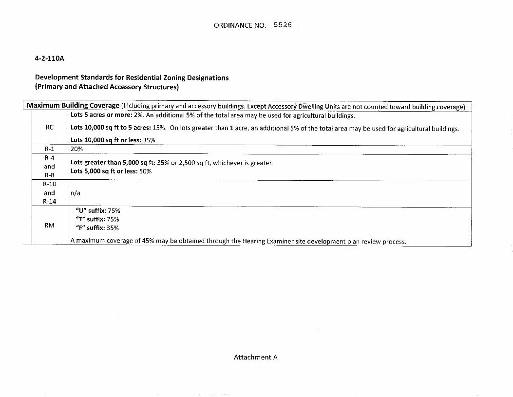
ORDINANCE NO. 5526
4-2-110A
Development Standards for Residential Zoning Designations (Primary and Attached Accessory Structures)
Maximum Building Coverage (Including primary and accessory buildings. Except Accessory Dwelling Units are not counted toward building coverage)
RC
R-l R-4 and R-8 R-10 and R-14
RM
Lots 5 acres or more: 2%. An additional 5% of the total area may be used for agricultural buildings.
Lots 10,000 sq ft to 5 acres: 15%. On lots greater than 1 acre, an additional 5% of the total area may be used for agricultural buildings.
Lots 10,000 sq ft or less: 35%.
20%
Lots greater than 5,000 sq ft: 35% or 2,500 sq ft, whichever is greater. Lots 5,000 sq ft or less: 50%
n/a
"U" suffix: 75% "T" suffix: 75% "F" suffix: 35%
A maximum coverage of 45% may be obtained through the Hearing Examiner site development plan review process.
Attachment A
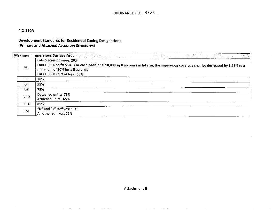
ORDINANCE NO. 5526
4-2-110A
Development Standards for Residential Zoning Designations (Primary and Attached Accessory Structures)
Maximum Impervious Surface Area
RC
R-l
R-4
R-8
Lots 5 acres or more: 20%
Lots 10,000 sq ft: 55%. For each additional 10,000 sq ft increase in lot size, the impervious coverage shall be decreased by 1.75% to a minimum of 20% for a 5 acre lot Lots 10,000 sq ft or less: 55%
30%
55%
75%
R-10
R-14
RM
Detached units: 75% Attached units: 65% 85% "U" and "T" suffixes: 85%. All other suffixes: 75%
Attachment B
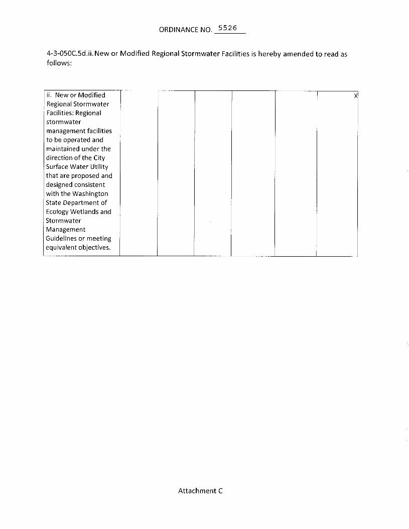
ORDINANCE NO. 5526
4-3-050C.5d.ii. New or Modified Regional Stormwater Facilities is hereby amended to read as follows:
ii. New or Modified Regional Stormwater Facilities: Regional stormwater management facilities to be operated and maintained under the direction of the City Surface Water Utility that are proposed and designed consistent with the Washington State Department of Ecology Wetlands and Stormwater Management Guidelines or meeting equivalent objectives.
X
Attachment C
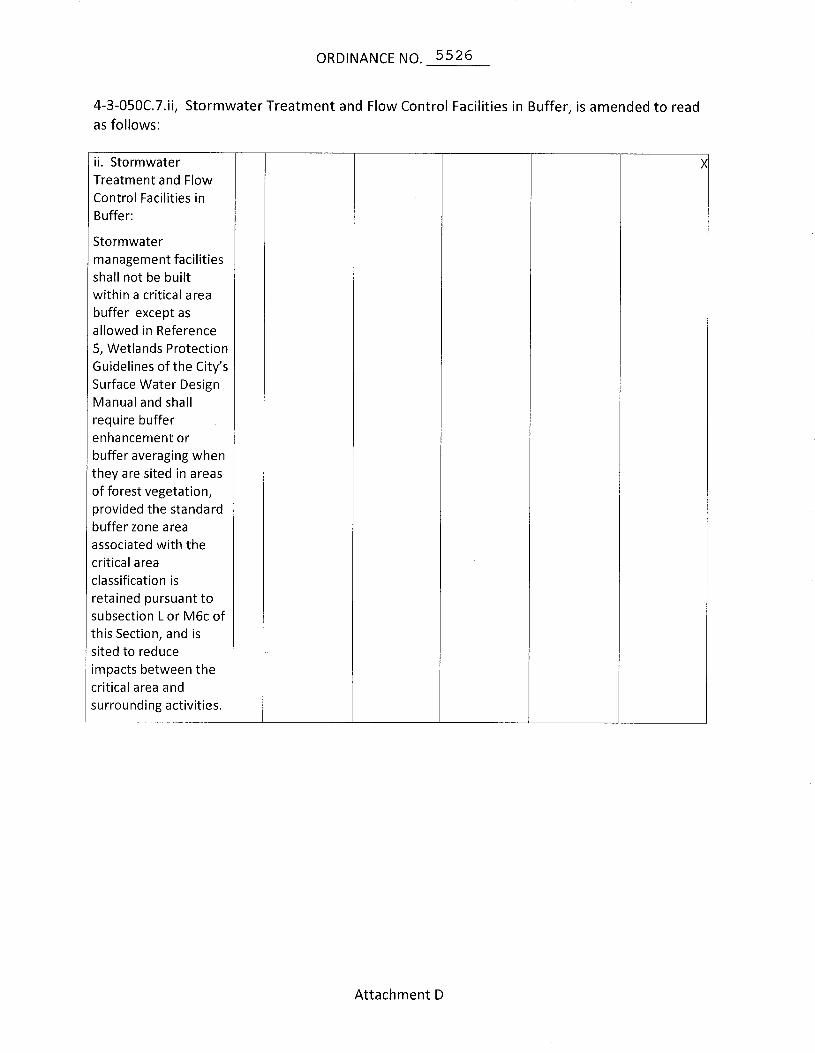
ORDINANCE NO. 5526
4-3-050C.7.ii, Stormwater Treatment and Flow Control Facilities in Buffer, is amended to read as follows:
ii. Stormwater Treatment and Flow Control Facilities in Buffer:
Stormwater management facilities shall not be built within a critical area buffer except as allowed in Reference 5, Wetlands Protection Guidelines of the City's Surface Water Design Manual and shall require buffer enhancement or buffer averaging when they are sited in areas of forest vegetation, provided the standard buffer zone area associated with the critical area classification is retained pursuant to subsection L or M6c of this Section, and is sited to reduce impacts between the critical area and surrounding activities.
Attachment D
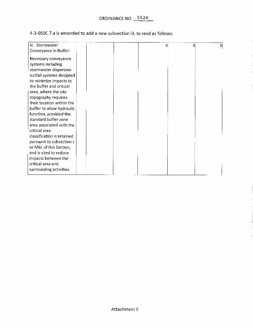
ORDINANCE NO. 5526
4-3-050C.7.a is amended to add a new subsection iii, to read as follows:
iii. Stormwater Conveyance in Buffer:
Necessary conveyance systems including stormwater dispersion outfall systems designed to minimize impacts to the buffer and critical area, where the site topography requires their location within the buffer to allow hydraulic function, provided the standard buffer zone area associated with the critical area
classification is retained pursuant to subsection L or M6c of this Section, and is sited to reduce impacts between the critical area and surrounding activities.
X X X
Attachment E
2009 Surface Water Design Manual Amendment City of Renton
CITY OF RENTON AMENDMENTS TO THE KING COUNTY
SURFACE WATER DESIGN MANUAL
REFERENCE 7-B STANDARD PLAN NOTES AND EXAMPLE CONSTRUCTION SEQUENCING

Page 1
Surface Water Standard Plan Notes and Example of Construction Sequence Surface Water Standard Plan Notes
1. These notes shall appear on projects for the surface water utility.
2. Before any construction or development activity occurs, a pre-construction meeting must be held between the City of Renton plan review section and the applicant.
3. All design and construction shall be in accordance with the Renton Municipal Code (RMC), the latest edition of the Standard Specifications for Road, Bridge and Municipal Construction prepared by WSDOT and the American Public Works Association (APWA), as amended by the City of Renton Public Works Department. It shall be the sole responsibility of the applicant and the professional civil engineer to correct any error, omission or variation from the above requirements found in this plans. all corrections shall be at no additional cost to the City.
4. Approval of this road, grading, parking and drainage plan does not constitute an approval of any other construction (e.g. domestic water conveyance, sewer conveyance, gas, electrical. etc.)The surface water drainage system shall be constructed according to the approved plans, which are on file in with the City. Any deviation from the approved plans will require written approval from the City of Renton Public Works Department, Surface Water Utility Section.
5. A copy of these approved plans must be on the job site whenever construction is in progress.
6. Grading activities (site alteration) are limited to the hours of 7 a.m. to 7 p.m. Monday through Saturday and no work on Sunday is allowed, unless otherwise approved with a written decision by the City of Renton.
7. It shall be the applicant’s/contractor’s responsibility to obtain all construction easements necessary before initiating off-site work. Easements require City review and approval prior to construction.
8. Franchised utilities or other installations that are not shown on these approved plans shall not be constructed unless an approved set of plans that meet all requirements of Chapter 4 of the Surface Water Design Manual are submitted to the City of Renton.
9. Datum shall be NAVD 88 unless otherwise approved by the City of Renton. Reference benchmark and elevations are noted on the plans.
10. Any dewatering system necessary for the construction of stormwater facilities must be submitted to the City for review and approval.
Page 2
11. All utility trenches and roadway subgrade shall be backfilled and compacted to 95 percent density, standard proctor.
12. Open cutting of existing roadways for non-franchised utility or storm drainage work is not allowed unless specifically approved by the City of Renton and noted on these approved plans. Any open cut shall be restored in accordance with the City of Renton trench restoration standards.
13. All sedimentation/erosion facilities must be in operation prior to clearing and building construction, and they must be satisfactorily maintained until construction is completed and the potential for on-site erosion has passed.
14. All retention/detention facilities must be installed and in operation prior to or in conjunction with all construction activity unless otherwise approved by the Public Works Department, Surface Water Utility Section.
15. All pipe and appurtenances shall be laid on a properly prepared foundation in accordance with the current State of Washington Standard Specification for Road and Bridge Construction. This shall include necessary leveling of the trench bottom or the top of the foundation material, as well as placement and compaction of required bedding material, to uniform grade so that the entire length of the pipe will be supported on a uniformly dense, unyielding base. All pipe bedding shall be APWA Class “C”, with the exception of PVC pipe.
16. Steel pipe shall be aluminized, or galvanized with asphalt treatment #1 or better inside and outside.
17. All drainage structures, such as catch basins and manholes shall have solid locking lids. All drainage structures associated with a permanent retention/detention facility shall have solid locking lids.
18. Building and other structures shall be placed in accordance with Table 4.1 Easement Widths and Building Setbacks Lines.
19. All catch basin grates shall be depressed 0.10 feet below pavement level.
20. All driveway culverts located within City of Renton right-of-way shall be of sufficient length to provide a minimum 3:1 slope from the edge of the driveway to the bottom of the ditch. Rock for erosion protection of roadside ditches, where required, shall be of sound quarry rock placed to a depth of one (1) foot and must meet the following specifications: 4 - 8 inch rock / 40 - 70% passing; 2 - 4 inch rock / 30 - 40% passing; and less than 2 inch rock / 10 - 20% passing.
21. All building downspouts and footing drains shall be connected to the storm drainage system, unless approved by the City plan reviewer or Surface Water Utility Section. An accurately dimensioned, certified as-built drawing of this drainage system will be submitted to the City upon completion.
Page 3
22. Drainage outlets (stub-outs) shall be provided for each individual lot, except for those lots approved for infiltration by the City. Stub-outs shall conform to the following:
a. Each outlet shall be suitably located at the lowest elevation on the lot, so as to service all future roof downspouts and footing drains, driveways, yard drains, and any other surface or subsurface drains necessary to render the lots suitable for their intended use. Each outlet shall have free-flowing, positive drainage to an approved stormwater conveyance system or to an approved outfall location.
b. Outlets on each lot shall be located with a five-foot-high, 2" x 4" stake marked "storm" or "drain". The stub-out shall extend above surface level, be visible, and be secured to the stake.
c. Pipe material shall conform to underdrain specifications described in Chapter 4 of the Surface Water Design Manual and, if non-metallic, the pipe shall be placed in a trench with a tracing wire above or other acceptable detection.
d. Private drainage easements are required for drainage systems designed to convey flows through individual lots.
e. The applicant/contractor is responsible for coordinating the locations of all stub-out conveyance lines with respect to other utilities (e.g. power, gas, telephone, television).
f. All individual stub-outs shall be privately owned and maintained by the lot home owner.
g. Storm drainage pipe systems shall not penetrate building foundations, except for sump pump discharge lines used to drain crawl spaces, provided the sump pump system includes backflow prevention or a check valve.
23. All disturbed pervious areas (compacted, graded, landscaped, etc.) of the development site must demonstrate one of the following: The existing duff layer shall be staged and redistributed to maintain the moisture capacity of the soil, OR; Amended soil shall be added to maintain the moisture capacity.
24. Proof of liability insurance shall be submitted to the City prior to construction permit issuance.
25. Issuance of the building or construction permits by the City of Renton does not relieve the owner of the continuing legal obligation and/or liability connected with storm surface water disposition. Further, the City of Renton does not accept any obligation for the proper functioning and maintenance of the system provided during construction.
26. The Contractor shall be responsible for providing adequate safeguard, safety devices, protective equipment, flaggers, and any other needed actions to protect the life, health, and safety of the public, and to protect property in connection with the
Page 4
performance of work. Any work within the traveled right-of-way that may interrupt normal traffic flow shall require a traffic control plan approve by the Public Works Department, Transportation Systems Division. All sections of the WSDOT Standard Specifications 1-07-23 Traffic Control shall apply.
27. Project located within the aquifer protection area (APA) shall comply with Special Requirement #6 of the Surface Water Design Manual and Aquifer Protection Regulations (RMC 4-3-050).

Page 5
Erosion Control Notes
1. These notes shall appear for all projects - site improvements, surface water utility,
wastewater utility, water utility, and transportation plans:
2. Before any construction or development activity occurs, a pre-construction meeting must be held with the City of Renton, public works design engineer.
3. The Boundaries of the clearing limits and areas of vegetation preservation as prescribed on the plan(s) shall be clearly flagged by survey tape or fencing in the field prior to construction in accordance with Appendix D of the Surface Water Design Manual and observed during construction. During the construction period, no disturbance beyond the clearing limits shall be permitted. The clearing limits shall be maintained by the applicant/ESC supervisor for the duration of construction.
4. Stabilized construction entrances shall be installed at the beginning of construction and maintained for the duration of the project. Additional measures, such as constructed wheel wash systems or wash pads, may be required to ensure that all paved areas are kept clean and track out to road right of way does not occur for the duration of the project.
5. All required sedimentation/erosion control facilities must be constructed and in operation prior to land clearing and/or construction to prevent transportation of sediment to surface water, drainage systems and adjacent properties. All erosion and sediment facilities shall be maintained in a satisfactory condition until such time that clearing and/or construction is complete and potential for on-site erosion has passed. The implementation, maintenance, replacement and additions to erosion/sedimentation control systems shall be the responsibility of the permitee.
6. The erosion and sedimentation control systems depicted on this drawing are intended to be minimum requirements to meet anticipated site conditions. As construction progresses and unexpected or seasonal conditions dictate, the permitee shall anticipate that more erosion and sedimentation control facilities will be necessary to ensure complete siltation control on the proposed site. During the course of construction, it shall be the obligation and responsibility of the permitee to address any new conditions that may be created by the activities and to provide additional facilities, over and above minimum requirements, as may be needed, to protect adjacent properties and water quality of the receiving drainage system.
7. Approval of this plan is for erosion/sedimentation control only. It does not constitute an approval of storm drainage design, size nor location of pipes, restrictors, channels, or retention facilities.
8. Any areas of exposed soils, including roadway embankments, that will not be disturbed for two days during the wet season (October 1st trough March 30th) or seven days during the dry season (April 1st tough September 30) shall be immediately stabilized with the approved ESC cover methods (e.g., seeding, mulching, plastic covering, etc.).
Page 6
9. Wet season seasonal erosion and sediment control requirements apply to all construction sites clearing between October 1 and March 30 inclusive, unless otherwise approved by the City through an adjustment process.
10. Cover measures will be applied in conformance with Appendix D of the Surface Water Design Manual.
11. Any area needing ESC measures, not requiring immediate attention, shall be addressed within seven (7) days.
12. The ESC facilities on inactive sites shall be inspected and maintained a minimum of once a month or within 24 hours following a storm event.
13. At no time shall more than one (1) foot of sediment be allowed to accumulate within a catch basin. All catch basins and conveyance lines shall be cleaned prior to paving. The cleaning operation shall not flush sediment-laden water into the downstream system.
14. During the time period of October 1st through March 30th, all project distributed soil areas greater, that are to be left un-worked for more than 12 hours, shall be covered by mulch, sodding or plastic covering.
15. Any permanent retention/detention facility used as a temporary settling basin shall be modified with the necessary erosion control measures and shall provide adequate storage capacity. If the permanent facility is to function ultimately as an infiltration system, the temporary facility must be rough graded so that the bottom and sides are at least three feet above the final grade of the permanent facility.
16. Prior to the beginning of the wet season (Oct. 1), all disturbed areas shall be reviewed to identify which ones can be seeded in preparation for the winter rains. Disturbed areas shall be seeded within one week of the beginning of the wet season. A sketch map of those areas to be seeded and those areas to remain uncovered shall be submitted to the City of Renton for review.
STRUCTURAL NOTES
1. These plans are approved for standard road and drainage improvements only. Plans for structures such as bridges, vaults, and retaining walls require a separate review and approval by the City prior to construction.
2. Rockeries are considered to be a method of bank stabilization and erosion control. Rockeries shall not be constructed to serve as retaining walls. All rockeries in City road right-of-way shall be constructed in accordance with City Standards. Rockeries outside of road right-of-way shall be constructed in accordance with the International Building Code.

Page 7
EROSION AND SEDIMENT CONTROL RECOMMENDED CONSTRUCTION SEQUENCE
1. Pre-construction meeting.
2. Post sign with name and phone number of ESC supervisor (may be consolidated with the required notice of construction sign).
3. Flag or fence clearing limits.
4. Install catch basin protection if required.
5. Grade and install construction entrance(s).
6. Install perimeter protection (silt fence, brush barrier, etc.).
7. Construct sediment ponds and traps.
8. Grade and stabilize construction roads.
9. Construct surface water controls (interceptor dikes, pipe slope drains, etc.) simultaneously with clearing and grading for project development.
10. Maintain erosion control measures in accordance with Appendix D of the Surface Water Design Manual and manufacturer's recommendations.
11. Relocate erosion control measures or install new measures so that as site conditions change the erosion and sediment control is always in accordance with the City’s Erosion and Sediment Control Standards.
12. Cover all areas that will be unworked for more than seven days during the dry season or two days during the wet season with straw, wood fiber mulch, compost, plastic sheeting or equivalent.
13. Stabilize all areas that reach final grade within seven days.
14. Seed or sod any areas to remain unworked for more than 30 days.
15. Upon completion of the project, all disturbed areas must be stabilized and BMPs removed if appropriate.

2009 Surface Water Design Manual Amendment City of Renton
CITY OF RENTON AMENDMENTS TO THE KING COUNTY
SURFACE WATER DESIGN MANUAL
REFERENCE 8 FORMS AND WORKSHEETS
8-H Bond Quantities Worksheet
8-I Maintenance and Defect Agreement
8-J Drainage Facility Covenant
8-K Drainage Release Covenant
8-L Drainage Easement
8-M Flow Control BMP Covenant
8-N Impervious Surface Limit Covenant
8-O Clearing Limit Covenant
8-P1 River Protection Easement – City of Renton
8-Q Leachable Metals Covenant

2009 Surface Water Design Manual Amendment City of Renton
CITY OF RENTON AMENDMENTS TO THE KING COUNTY
SURFACE WATER DESIGN MANUAL
REFERENCE 8-H BOND QUANTITIES WORKSHEET

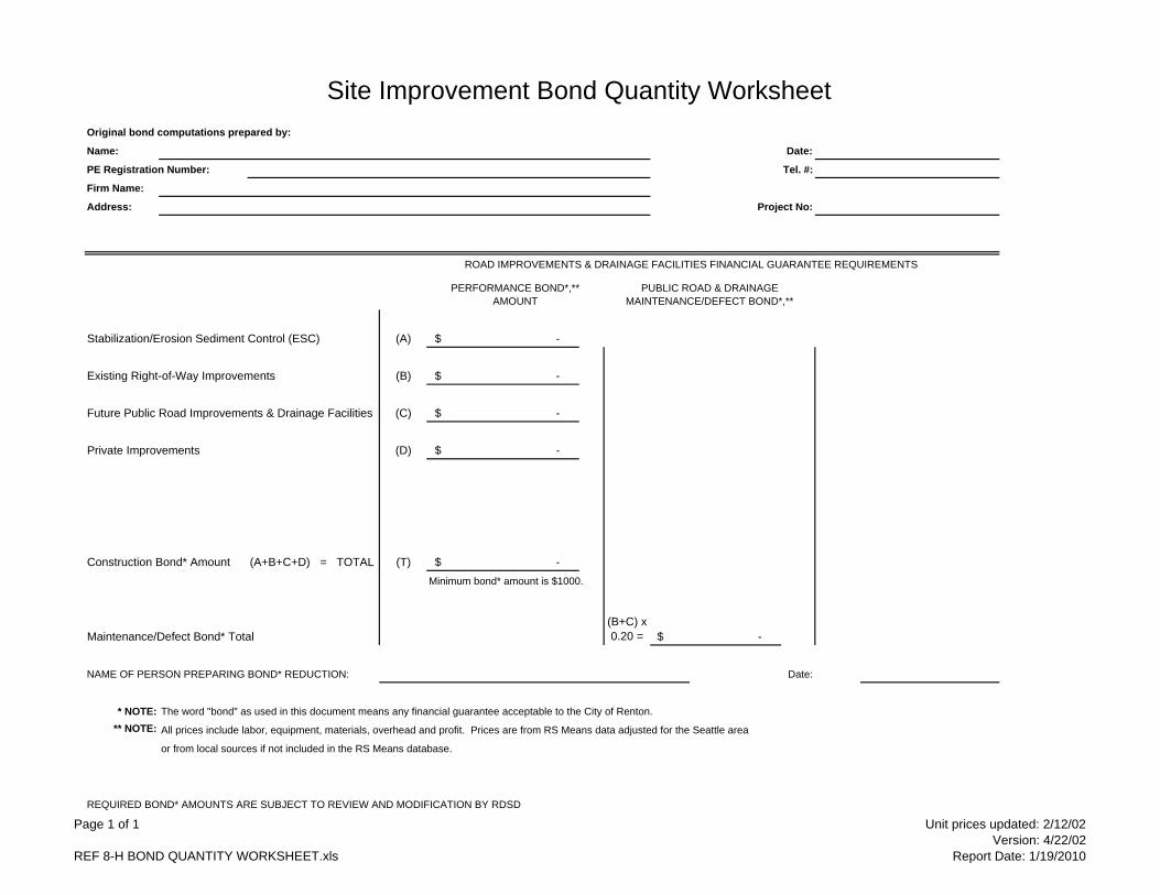
Site Improvement Bond Quantity WorksheetOriginal bond computations prepared by:
Name: Date:
PE Registration Number: Tel. #:
Firm Name:
Address: Project No:
Stabilization/Erosion Sediment Control (ESC) (A)
Existing Right-of-Way Improvements (B)
Future Public Road Improvements & Drainage Facilities (C)
Private Improvements (D)
Construction Bond* Amount (A+B+C+D) = TOTAL (T)Minimum bond* amount is $1000.
Maintenance/Defect Bond* Total
NAME OF PERSON PREPARING BOND* REDUCTION: Date:
* NOTE: The word "bond" as used in this document means any financial guarantee acceptable to the City of Renton.** NOTE: All prices include labor, equipment, materials, overhead and profit. Prices are from RS Means data adjusted for the Seattle area
or from local sources if not included in the RS Means database.
REQUIRED BOND* AMOUNTS ARE SUBJECT TO REVIEW AND MODIFICATION BY RDSD
-$
-$
-$
(B+C) x 0.20 = -$
ROAD IMPROVEMENTS & DRAINAGE FACILITIES FINANCIAL GUARANTEE REQUIREMENTS
PERFORMANCE BOND*,**AMOUNT
PUBLIC ROAD & DRAINAGE MAINTENANCE/DEFECT BOND*,**
-$
-$
Page 1 of 1
REF 8-H BOND QUANTITY WORKSHEET.xls
Unit prices updated: 2/12/02Version: 4/22/02
Report Date: 1/19/2010
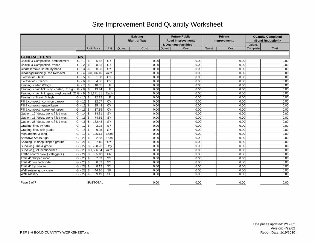
Site Improvement Bond Quantity WorksheetExisting Future Public Private
Right-of-Way Road Improvements Improvements & Drainage Facilities Quant.
Unit Price Unit Quant. Cost Quant. Cost Quant. Cost Complete Cost
GENERAL ITEMS No.Backfill & Compaction- embankment GI - 1 5.62$ CY 0.00 0.00 0.00 0.00Backfill & Compaction- trench GI - 2 8.53$ CY 0.00 0.00 0.00 0.00Clear/Remove Brush, by hand GI - 3 0.36$ SY 0.00 0.00 0.00 0.00Clearing/Grubbing/Tree Removal GI - 4 8,876.16$ Acre 0.00 0.00 0.00 0.00Excavation - bulk GI - 5 1.50$ CY 0.00 0.00 0.00 0.00Excavation - Trench GI - 6 4.06$ CY 0.00 0.00 0.00 0.00Fencing, cedar, 6' high GI - 7 18.55$ LF 0.00 0.00 0.00 0.00Fencing, chain link, vinyl coated, 6' high GI - 8 13.44$ LF 0.00 0.00 0.00 0.00Fencing, chain link, gate, vinyl coated, 20 GI - 9 1,271.81$ Each 0.00 0.00 0.00 0.00Fencing, split rail, 3' high GI - 10 12.12$ LF 0.00 0.00 0.00 0.00Fill & compact - common barrow GI - 11 22.57$ CY 0.00 0.00 0.00 0.00Fill & compact - gravel base GI - 12 25.48$ CY 0.00 0.00 0.00 0.00Fill & compact - screened topsoil GI - 13 37.85$ CY 0.00 0.00 0.00 0.00Gabion, 12" deep, stone filled mesh GI - 14 54.31$ SY 0.00 0.00 0.00 0.00Gabion, 18" deep, stone filled mesh GI - 15 74.85$ SY 0.00 0.00 0.00 0.00Gabion, 36" deep, stone filled mesh GI - 16 132.48$ SY 0.00 0.00 0.00 0.00Grading, fine, by hand GI - 17 2.02$ SY 0.00 0.00 0.00 0.00Grading, fine, with grader GI - 18 0.95$ SY 0.00 0.00 0.00 0.00Monuments, 3' long GI - 19 135.13$ Each 0.00 0.00 0.00 0.00Sensitive Areas Sign GI - 20 2.88$ Each 0.00 0.00 0.00 0.00Sodding, 1" deep, sloped ground GI - 21 7.46$ SY 0.00 0.00 0.00 0.00Surveying, line & grade GI - 22 788.26$ Day 0.00 0.00 0.00 0.00Surveying, lot location/lines GI - 23 1,556.64$ Acre 0.00 0.00 0.00 0.00Traffic control crew ( 2 flaggers ) GI - 24 85.18$ HR 0.00 0.00 0.00 0.00Trail, 4" chipped wood GI - 25 7.59$ SY 0.00 0.00 0.00 0.00Trail, 4" crushed cinder GI - 26 8.33$ SY 0.00 0.00 0.00 0.00Trail, 4" top course GI - 27 8.19$ SY 0.00 0.00 0.00 0.00Wall, retaining, concrete GI - 28 44.16$ SF 0.00 0.00 0.00 0.00Wall, rockery GI - 29 9.49$ SF 0.00 0.00 0.00 0.00
Page 2 of 7 SUBTOTAL 0.00 0.00 0.00 0.00
Quantity Completed (Bond Reduction)*
REF 8-H BOND QUANTITY WORKSHEET.xls
Unit prices updated: 2/12/02Version: 4/22/02
Report Date: 1/19/2010
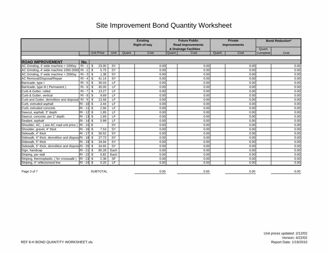
Site Improvement Bond Quantity Worksheet
Existing Future Public Private Bond Reduction*Right-of-way Road Improvements Improvements
& Drainage Facilities Quant.Unit Price Unit Quant. Cost Quant. Cost Quant. Cost Complete Cost
ROAD IMPROVEMENT No.AC Grinding, 4' wide machine < 1000sy RI - 1 23.00$ SY 0.00 0.00 0.00 0.00AC Grinding, 4' wide machine 1000-2000sRI - 2 5.75$ SY 0.00 0.00 0.00 0.00AC Grinding, 4' wide machine > 2000sy RI - 3 1.38$ SY 0.00 0.00 0.00 0.00AC Removal/Disposal/Repair RI - 4 41.14$ SY 0.00 0.00 0.00 0.00Barricade, type I RI - 5 30.03$ LF 0.00 0.00 0.00 0.00Barricade, type III ( Permanent ) RI - 6 45.05$ LF 0.00 0.00 0.00 0.00Curb & Gutter, rolled RI - 7 13.27$ LF 0.00 0.00 0.00 0.00Curb & Gutter, vertical RI - 8 9.69$ LF 0.00 0.00 0.00 0.00Curb and Gutter, demolition and disposal RI - 9 13.58$ LF 0.00 0.00 0.00 0.00Curb, extruded asphalt RI - 10 2.44$ LF 0.00 0.00 0.00 0.00Curb, extruded concrete RI - 11 2.56$ LF 0.00 0.00 0.00 0.00Sawcut, asphalt, 3" depth RI - 12 1.85$ LF 0.00 0.00 0.00 0.00Sawcut, concrete, per 1" depth RI - 13 1.69$ LF 0.00 0.00 0.00 0.00Sealant, asphalt RI - 14 0.99$ LF 0.00 0.00 0.00 0.00Shoulder, AC, ( see AC road unit price ) RI - 15 -$ SY 0.00 0.00 0.00 0.00Shoulder, gravel, 4" thick RI - 16 7.53$ SY 0.00 0.00 0.00 0.00Sidewalk, 4" thick RI - 17 30.52$ SY 0.00 0.00 0.00 0.00Sidewalk, 4" thick, demolition and disposaRI - 18 27.73$ SY 0.00 0.00 0.00 0.00Sidewalk, 5" thick RI - 19 34.94$ SY 0.00 0.00 0.00 0.00Sidewalk, 5" thick, demolition and disposaRI - 20 34.65$ SY 0.00 0.00 0.00 0.00Sign, handicap RI - 21 85.28$ Each 0.00 0.00 0.00 0.00Striping, per stall RI - 22 5.82$ Each 0.00 0.00 0.00 0.00Striping, thermoplastic, ( for crosswalk ) RI - 23 2.38$ SF 0.00 0.00 0.00 0.00Striping, 4" reflectorized line RI - 24 0.25$ LF 0.00 0.00 0.00 0.00
Page 3 of 7 SUBTOTAL 0.00 0.00 0.00 0.00
REF 8-H BOND QUANTITY WORKSHEET.xls
Unit prices updated: 2/12/02Version: 4/22/02
Report Date: 1/19/2010
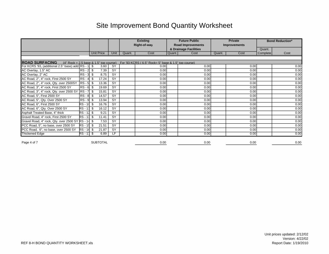
Site Improvement Bond Quantity Worksheet
Existing Future Public Private Bond Reduction*Right-of-way Road Improvements Improvements
& Drainage Facilities Quant.Unit Price Unit Quant. Cost Quant. Cost Quant. Cost Complete Cost
ROAD SURFACING (4" Rock = 2.5 base & 1.5" top course) For '93 KCRS ( 6.5" Rock= 5" base & 1.5" top course)For KCRS '93, (additional 2.5" base) add: RS - 1 3.60$ SY 0.00 0.00 0.00 0.00AC Overlay, 1.5" AC RS - 2 7.39$ SY 0.00 0.00 0.00 0.00AC Overlay, 2" AC RS - 3 8.75$ SY 0.00 0.00 0.00 0.00AC Road, 2", 4" rock, First 2500 SY RS - 4 17.24$ SY 0.00 0.00 0.00 0.00AC Road, 2", 4" rock, Qty. over 2500SY RS - 5 13.36$ SY 0.00 0.00 0.00 0.00AC Road, 3", 4" rock, First 2500 SY RS - 6 19.69$ SY 0.00 0.00 0.00 0.00AC Road, 3", 4" rock, Qty. over 2500 SY RS - 7 15.81$ SY 0.00 0.00 0.00 0.00AC Road, 5", First 2500 SY RS - 8 14.57$ SY 0.00 0.00 0.00 0.00AC Road, 5", Qty. Over 2500 SY RS - 9 13.94$ SY 0.00 0.00 0.00 0.00AC Road, 6", First 2500 SY RS - 10 16.76$ SY 0.00 0.00 0.00 0.00AC Road, 6", Qty. Over 2500 SY RS - 11 16.12$ SY 0.00 0.00 0.00 0.00Asphalt Treated Base, 4" thick RS - 12 9.21$ SY 0.00 0.00 0.00 0.00Gravel Road, 4" rock, First 2500 SY RS - 13 11.41$ SY 0.00 0.00 0.00 0.00Gravel Road, 4" rock, Qty. over 2500 SY RS - 14 7.53$ SY 0.00 0.00 0.00 0.00PCC Road, 5", no base, over 2500 SY RS - 15 21.51$ SY 0.00 0.00 0.00 0.00PCC Road, 6", no base, over 2500 SY RS - 16 21.87$ SY 0.00 0.00 0.00 0.00Thickened Edge RS - 17 6.89$ LF 0.00 0.00 0.00 0.00
Page 4 of 7 SUBTOTAL 0.00 0.00 0.00 0.00
REF 8-H BOND QUANTITY WORKSHEET.xls
Unit prices updated: 2/12/02Version: 4/22/02
Report Date: 1/19/2010

Site Improvement Bond Quantity Worksheet
Existing Future Public Private Bond Reduction*Right-of-way Road Improvements Improvements
& Drainage Facilities Quant.Unit Price Unit Quant. Cost Quant. Cost Quant. Cost Complete Cost
DRAINAGE (CPP = Corrugated Plastic Pipe, N12 or Equivalent) For Culvert prices, Average of 4' cover was assumed. Assume perforated PVC is same price as solid pipe.Access Road, R/D D - 1 16.74$ SY 0.00 0.00 0.00 0.00Bollards - fixed D - 2 240.74$ Each 0.00 0.00 0.00 0.00Bollards - removable D - 3 452.34$ Each 0.00 0.00 0.00 0.00* (CBs include frame and lid)CB Type I D - 4 1,257.64$ Each 0.00 0.00 0.00 0.00CB Type IL D - 5 1,433.59$ Each 0.00 0.00 0.00 0.00CB Type II, 48" diameter D - 6 2,033.57$ Each 0.00 0.00 0.00 0.00 for additional depth over 4' D - 7 436.52$ FT 0.00 0.00 0.00 0.00CB Type II, 54" diameter D - 8 2,192.54$ Each 0.00 0.00 0.00 0.00 for additional depth over 4' D - 9 486.53$ FT 0.00 0.00 0.00 0.00CB Type II, 60" diameter D - 10 2,351.52$ Each 0.00 0.00 0.00 0.00 for additional depth over 4' D - 11 536.54$ FT 0.00 0.00 0.00 0.00CB Type II, 72" diameter D - 12 3,212.64$ Each 0.00 0.00 0.00 0.00 for additional depth over 4' D - 13 692.21$ FT 0.00 0.00 0.00 0.00Through-curb Inlet Framework (Add) D - 14 366.09$ Each 0.00 0.00 0.00 0.00Cleanout, PVC, 4" D - 15 130.55$ Each 0.00 0.00 0.00 0.00Cleanout, PVC, 6" D - 16 174.90$ Each 0.00 0.00 0.00 0.00Cleanout, PVC, 8" D - 17 224.19$ Each 0.00 0.00 0.00 0.00Culvert, PVC, 4" D - 18 8.64$ LF 0.00 0.00 0.00 0.00Culvert, PVC, 6" D - 19 12.60$ LF 0.00 0.00 0.00 0.00Culvert, PVC, 8" D - 20 13.33$ LF 0.00 0.00 0.00 0.00Culvert, PVC, 12" D - 21 21.77$ LF 0.00 0.00 0.00 0.00Culvert, CMP, 8" D - 22 17.25$ LF 0.00 0.00 0.00 0.00Culvert, CMP, 12" D - 23 26.45$ LF 0.00 0.00 0.00 0.00Culvert, CMP, 15" D - 24 32.73$ LF 0.00 0.00 0.00 0.00Culvert, CMP, 18" D - 25 37.74$ LF 0.00 0.00 0.00 0.00Culvert, CMP, 24" D - 26 53.33$ LF 0.00 0.00 0.00 0.00Culvert, CMP, 30" D - 27 71.45$ LF 0.00 0.00 0.00 0.00Culvert, CMP, 36" D - 28 112.11$ LF 0.00 0.00 0.00 0.00Culvert, CMP, 48" D - 29 140.83$ LF 0.00 0.00 0.00 0.00Culvert, CMP, 60" D - 30 235.45$ LF 0.00 0.00 0.00 0.00Culvert, CMP, 72" D - 31 302.58$ LF 0.00 0.00 0.00 0.00
Page 5 of 7 SUBTOTAL 0.00 0.00 0.00 0.00
REF 8-H BOND QUANTITY WORKSHEET.xls
Unit prices updated: 2/12/02Version: 4/22/02
Report Date: 1/19/2010
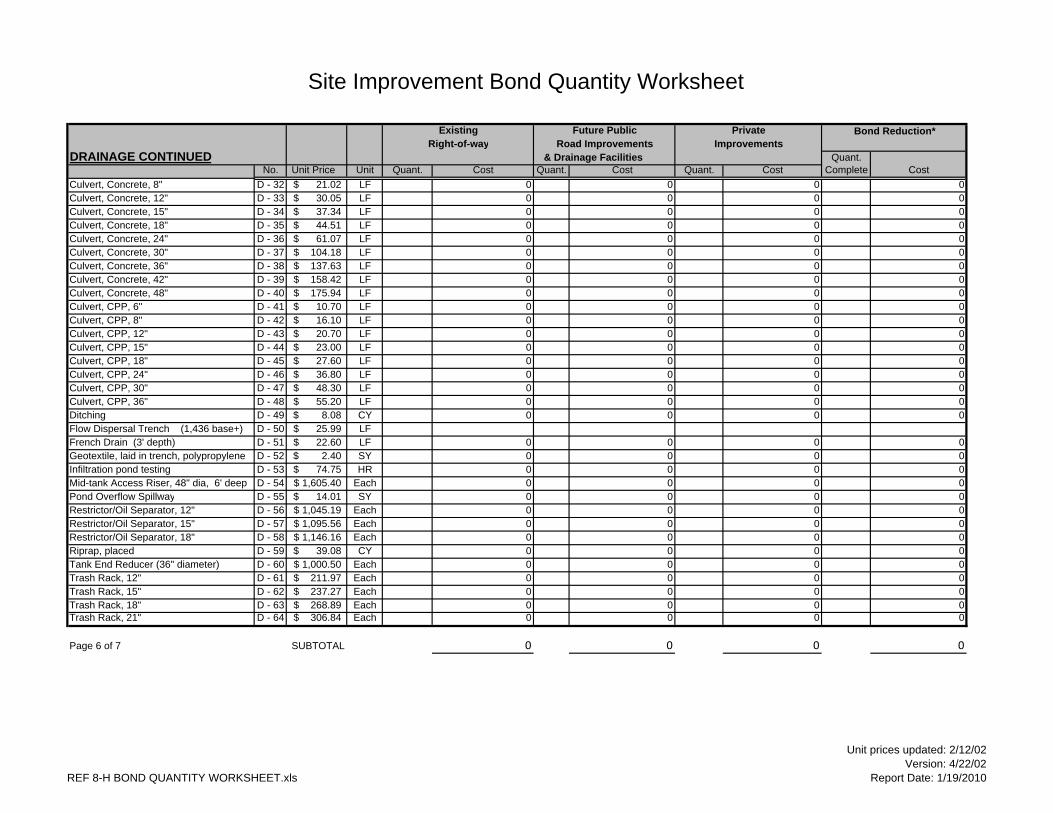
Site Improvement Bond Quantity Worksheet
Existing Future Public Private Bond Reduction*Right-of-way Road Improvements Improvements
DRAINAGE CONTINUED & Drainage Facilities Quant.No. Unit Price Unit Quant. Cost Quant. Cost Quant. Cost Complete Cost
Culvert, Concrete, 8" D - 32 21.02$ LF 0 0 0 0Culvert, Concrete, 12" D - 33 30.05$ LF 0 0 0 0Culvert, Concrete, 15" D - 34 37.34$ LF 0 0 0 0Culvert, Concrete, 18" D - 35 44.51$ LF 0 0 0 0Culvert, Concrete, 24" D - 36 61.07$ LF 0 0 0 0Culvert, Concrete, 30" D - 37 104.18$ LF 0 0 0 0Culvert, Concrete, 36" D - 38 137.63$ LF 0 0 0 0Culvert, Concrete, 42" D - 39 158.42$ LF 0 0 0 0Culvert, Concrete, 48" D - 40 175.94$ LF 0 0 0 0Culvert, CPP, 6" D - 41 10.70$ LF 0 0 0 0Culvert, CPP, 8" D - 42 16.10$ LF 0 0 0 0Culvert, CPP, 12" D - 43 20.70$ LF 0 0 0 0Culvert, CPP, 15" D - 44 23.00$ LF 0 0 0 0Culvert, CPP, 18" D - 45 27.60$ LF 0 0 0 0Culvert, CPP, 24" D - 46 36.80$ LF 0 0 0 0Culvert, CPP, 30" D - 47 48.30$ LF 0 0 0 0Culvert, CPP, 36" D - 48 55.20$ LF 0 0 0 0Ditching D - 49 8.08$ CY 0 0 0 0Flow Dispersal Trench (1,436 base+) D - 50 25.99$ LFFrench Drain (3' depth) D - 51 22.60$ LF 0 0 0 0Geotextile, laid in trench, polypropylene D - 52 2.40$ SY 0 0 0 0Infiltration pond testing D - 53 74.75$ HR 0 0 0 0Mid-tank Access Riser, 48" dia, 6' deep D - 54 1,605.40$ Each 0 0 0 0Pond Overflow Spillway D - 55 14.01$ SY 0 0 0 0Restrictor/Oil Separator, 12" D - 56 1,045.19$ Each 0 0 0 0Restrictor/Oil Separator, 15" D - 57 1,095.56$ Each 0 0 0 0Restrictor/Oil Separator, 18" D - 58 1,146.16$ Each 0 0 0 0Riprap, placed D - 59 39.08$ CY 0 0 0 0Tank End Reducer (36" diameter) D - 60 1,000.50$ Each 0 0 0 0Trash Rack, 12" D - 61 211.97$ Each 0 0 0 0Trash Rack, 15" D - 62 237.27$ Each 0 0 0 0Trash Rack, 18" D - 63 268.89$ Each 0 0 0 0Trash Rack, 21" D - 64 306.84$ Each 0 0 0 0
Page 6 of 7 SUBTOTAL 0 0 0 0
REF 8-H BOND QUANTITY WORKSHEET.xls
Unit prices updated: 2/12/02Version: 4/22/02
Report Date: 1/19/2010
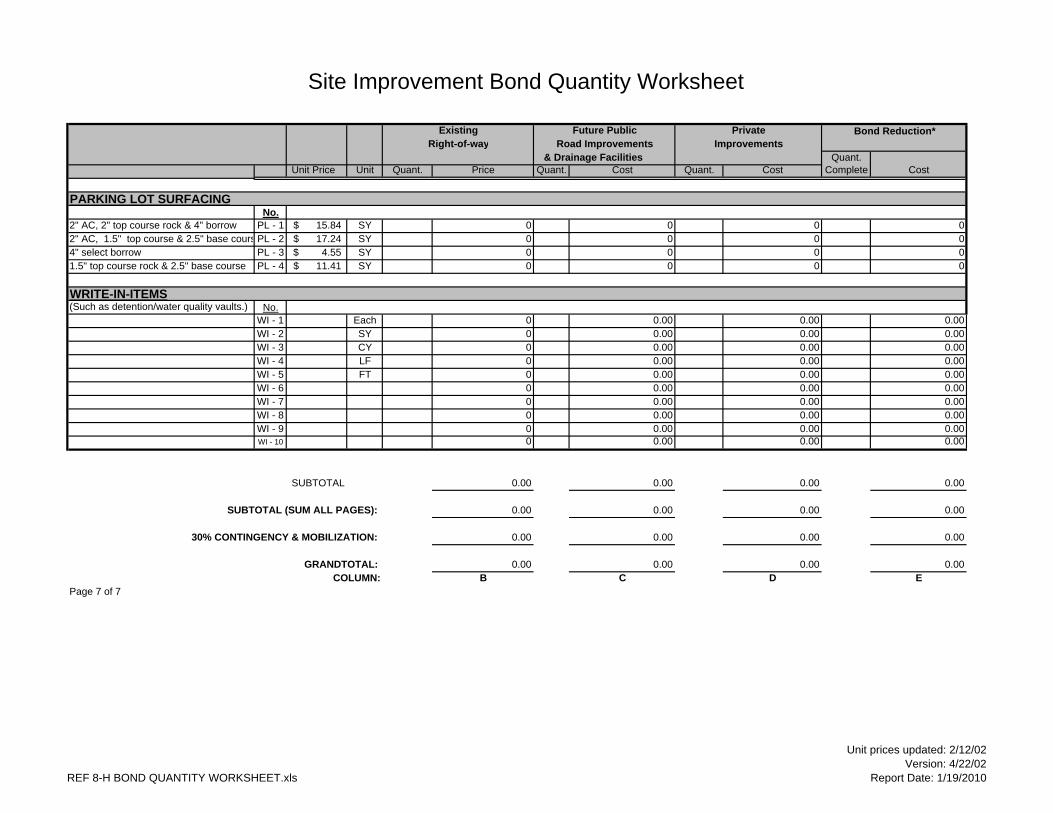
Site Improvement Bond Quantity Worksheet
Existing Future Public Private Bond Reduction*Right-of-way Road Improvements Improvements
& Drainage Facilities Quant.Unit Price Unit Quant. Price Quant. Cost Quant. Cost Complete Cost
PARKING LOT SURFACINGNo.
2" AC, 2" top course rock & 4" borrow PL - 1 15.84$ SY 0 0 0 02" AC, 1.5" top course & 2.5" base cours PL - 2 17.24$ SY 0 0 0 04" select borrow PL - 3 4.55$ SY 0 0 0 01.5" top course rock & 2.5" base course PL - 4 11.41$ SY 0 0 0 0
WRITE-IN-ITEMS(Such as detention/water quality vaults.) No.
WI - 1 Each 0 0.00 0.00 0.00WI - 2 SY 0 0.00 0.00 0.00WI - 3 CY 0 0.00 0.00 0.00WI - 4 LF 0 0.00 0.00 0.00WI - 5 FT 0 0.00 0.00 0.00WI - 6 0 0.00 0.00 0.00WI - 7 0 0.00 0.00 0.00WI - 8 0 0.00 0.00 0.00WI - 9 0 0.00 0.00 0.00WI - 10 0 0.00 0.00 0.00
SUBTOTAL 0.00 0.00 0.00 0.00
SUBTOTAL (SUM ALL PAGES): 0.00 0.00 0.00 0.00
30% CONTINGENCY & MOBILIZATION: 0.00 0.00 0.00 0.00
GRANDTOTAL: 0.00 0.00 0.00 0.00COLUMN: B C D E
Page 7 of 7
REF 8-H BOND QUANTITY WORKSHEET.xls
Unit prices updated: 2/12/02Version: 4/22/02
Report Date: 1/19/2010


2009 Surface Water Design Manual Amendment City of Renton
CITY OF RENTON AMENDMENTS TO THE KING COUNTY
SURFACE WATER DESIGN MANUAL
REFERENCE 8-I MAINTENANCE AND DEFECT AGREEMENT

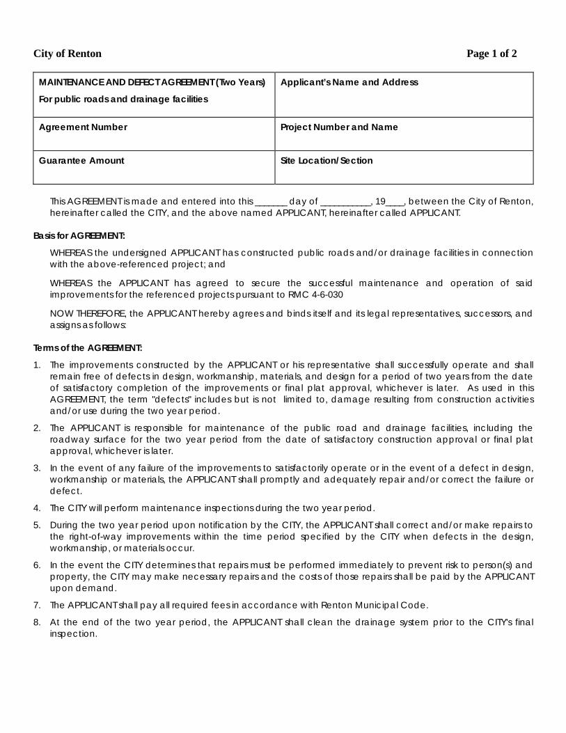
City of Renton Page 1 of 2
MAINTENANCE AND DEFECT AGREEMENT (Two Years)
For public roads and drainage facilities
Applicant’s Name and Address
Agreement Number
Project Number and Name
Guarantee Amount
Site Location/Section
This AGREEMENT is made and entered into this _______ day of ___________, 19____, between the City of Renton, hereinafter called the CITY, and the above named APPLICANT, hereinafter called APPLICANT.
Basis for AGREEMENT:
WHEREAS the undersigned APPLICANT has constructed public roads and/or drainage facilities in connection with the above-referenced project; and
WHEREAS the APPLICANT has agreed to secure the successful maintenance and operation of said improvements for the referenced projects pursuant to RMC 4-6-030
NOW THEREFORE, the APPLICANT hereby agrees and binds itself and its legal representatives, successors, and assigns as follows:
Terms of the AGREEMENT:
1. The improvements constructed by the APPLICANT or his representative shall successfully operate and shall remain free of defects in design, workmanship, materials, and design for a period of two years from the date of satisfactory completion of the improvements or final plat approval, whichever is later. As used in this AGREEMENT, the term "defects" includes but is not limited to, damage resulting from construction activities and/or use during the two year period.
2. The APPLICANT is responsible for maintenance of the public road and drainage facilities, including the roadway surface for the two year period from the date of satisfactory construction approval or final plat approval, whichever is later.
3. In the event of any failure of the improvements to satisfactorily operate or in the event of a defect in design, workmanship or materials, the APPLICANT shall promptly and adequately repair and/or correct the failure or defect.
4. The CITY will perform maintenance inspections during the two year period.
5. During the two year period upon notification by the CITY, the APPLICANT shall correct and/or make repairs to the right-of-way improvements within the time period specified by the CITY when defects in the design, workmanship, or materials occur.
6. In the event the CITY determines that repairs must be performed immediately to prevent risk to person(s) and property, the CITY may make necessary repairs and the costs of those repairs shall be paid by the APPLICANT upon demand.
7. The APPLICANT shall pay all required fees in accordance with Renton Municipal Code.
8. At the end of the two year period, the APPLICANT shall clean the drainage system prior to the CITY's final inspection.
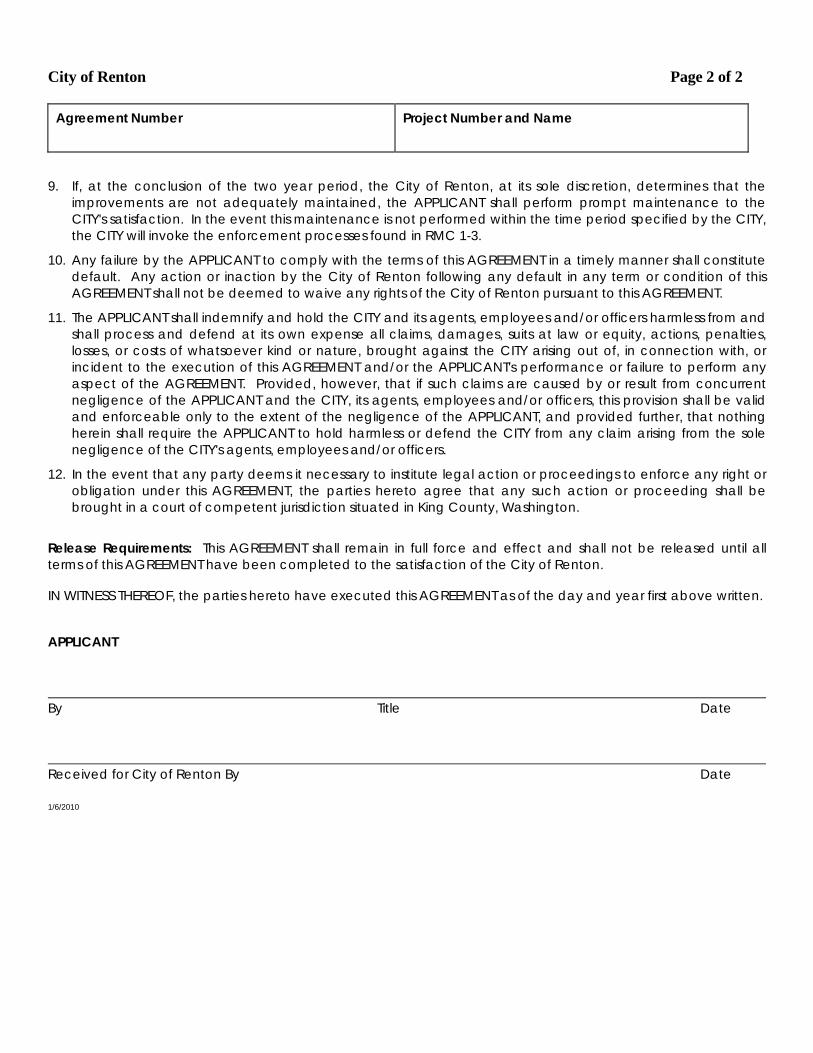
City of Renton Page 2 of 2
Agreement Number
Project Number and Name
9. If, at the conclusion of the two year period, the City of Renton, at its sole discretion, determines that the improvements are not adequately maintained, the APPLICANT shall perform prompt maintenance to the CITY's satisfaction. In the event this maintenance is not performed within the time period specified by the CITY, the CITY will invoke the enforcement processes found in RMC 1-3.
10. Any failure by the APPLICANT to comply with the terms of this AGREEMENT in a timely manner shall constitute default. Any action or inaction by the City of Renton following any default in any term or condition of this AGREEMENT shall not be deemed to waive any rights of the City of Renton pursuant to this AGREEMENT.
11. The APPLICANT shall indemnify and hold the CITY and its agents, employees and/or officers harmless from and shall process and defend at its own expense all claims, damages, suits at law or equity, actions, penalties, losses, or costs of whatsoever kind or nature, brought against the CITY arising out of, in connection with, or incident to the execution of this AGREEMENT and/or the APPLICANT's performance or failure to perform any aspect of the AGREEMENT. Provided, however, that if such claims are caused by or result from concurrent negligence of the APPLICANT and the CITY, its agents, employees and/or officers, this provision shall be valid and enforceable only to the extent of the negligence of the APPLICANT, and provided further, that nothing herein shall require the APPLICANT to hold harmless or defend the CITY from any claim arising from the sole negligence of the CITY's agents, employees and/or officers.
12. In the event that any party deems it necessary to institute legal action or proceedings to enforce any right or obligation under this AGREEMENT, the parties hereto agree that any such action or proceeding shall be brought in a court of competent jurisdiction situated in King County, Washington.
Release Requirements: This AGREEMENT shall remain in full force and effect and shall not be released until all terms of this AGREEMENT have been completed to the satisfaction of the City of Renton. IN WITNESS THEREOF, the parties hereto have executed this AGREEMENT as of the day and year first above written. APPLICANT By Title Date Received for City of Renton By Date 1/6/2010
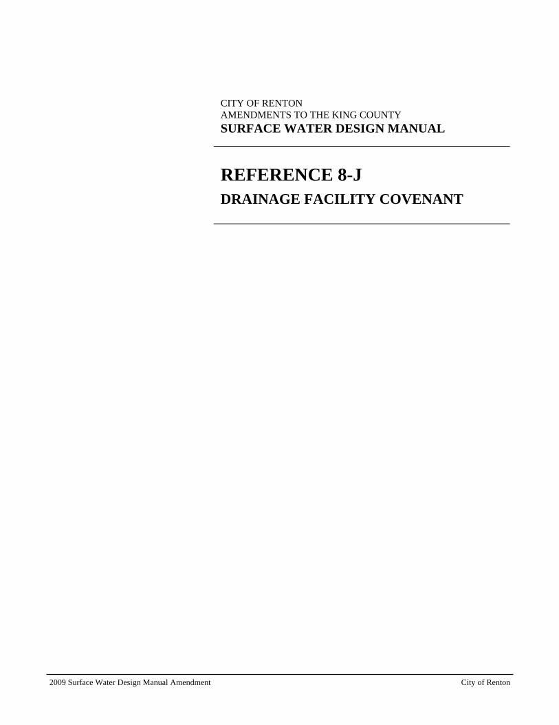
2009 Surface Water Design Manual Amendment City of Renton
CITY OF RENTON AMENDMENTS TO THE KING COUNTY
SURFACE WATER DESIGN MANUAL
REFERENCE 8-J DRAINAGE FACILITY COVENANT

Return Address: City Clerk’s Office City of Renton 1055 S Grady Way Renton, WA 98057
DECLARATION OF COVENANT FOR INSPECTION AND MAINTENANCE OF STORMWATER FACILITIES AND BMPS Grantor: Grantee: City of Renton Legal Description: Assessor's Tax Parcel ID#:
IN CONSIDERATION of the approved City of Renton ___________________________ permit for application file No. LUA/SWP_______________________ relating to the real property ("Property") described above, the Grantor(s), the owner(s) in fee of that Property, hereby covenants(covenant) with the City of Renton, a political subdivision of the state of Washington, that he/she(they) will observe, consent to, and abide by the conditions and obligations set forth and described in Paragraphs 1 through 10 below with regard to the Property, and hereby grants(grant) an easement as described in Paragraphs 2 and 3. Grantor(s) hereby grants(grant), covenants(covenant), and agrees(agree) as follows:
1. The Grantor(s) or his/her(their) successors in interest and assigns ("Owners of the described property") shall at their own cost, operate, maintain, and keep in good repair, the Property's stormwater facilities and/or best management practices ("BMPs") constructed as required in the approved construction plans and specifications __________ on file with the City of Renton and submitted to the City of Renton for the review and approval of permit(s) _____________________________. The property's stormwater facilities and/or best management practices ("BMPs") are shown and/or listed on Exhibit A. The property’s stormwater facilities and/or BMPs shall be maintained in compliance with the operation and maintenance schedule included and attached herein as Exhibit B. Stormwater facilities include pipes, swales, tanks, vaults, ponds, and other engineered structures designed to manage and/or treat stormwater on the Property. Stormwater BMPs include dispersion and infiltration devices, native vegetated areas, permeable pavements, vegetated roofs, rainwater harvesting systems, reduced impervious surface coverage, and other measures designed to reduce the amount of stormwater runoff on the Property.
2. City of Renton shall have the right to ingress and egress over those portions of the Property necessary to perform inspections of the stormwater facilities and BMPs and conduct maintenance activities specified in this Declaration of Covenant and in accordance with RMC 4-6-030.
3. If City of Renton determines that maintenance or repair work is required to be done to any of the stormwater facilities or BMPs, City of Renton shall give notice of the specific maintenance and/or repair work required pursuant to RMC 4-6-030. The City shall also set a reasonable time in which such
Page 1 of 3 Form Approved by City Attorney 10/2013
work is to be completed by the Owners. If the above required maintenance or repair is not completed within the time set by the City, the City may perform the required maintenance or repair, and hereby is given access to the Property, subject to the exclusion in Paragraph 2 above, for such purposes. Written notice will be sent to the Owners stating the City’s intention to perform such work. This work will not commence until at least seven (7) days after such notice is mailed. If, within the sole discretion of the City, there exists an imminent or present danger, the seven (7) day notice period will be waived and maintenance and/or repair work will begin immediately.
4. If at any time the City of Renton reasonably determines that a stormwater facility or BMP on the Property creates any of the hazardous conditions listed in RMC 4-4-060 G or relevant municipal successor's codes as applicable and herein incorporated by reference, the City may take measures specified therein.
5. The Owners shall assume all responsibility for the cost of any maintenance or repair work completed by the City as described in Paragraph 3 or any measures taken by the City to address hazardous conditions as described in Paragraph 4. Such responsibility shall include reimbursement to the City within thirty (30) days of the receipt of the invoice for any such work performed. Overdue payments will require payment of interest at the current legal rate as liquidated damages. If legal action ensues, the prevailing party is entitled to recover reasonable litigation costs and attorney’s fees.
6. The Owners are hereby required to obtain written approval from City of Renton prior to filling, piping, cutting, or removing vegetation (except in routine landscape maintenance) in open vegetated stormwater facilities (such as swales, channels, ditches, ponds, etc.), or performing any alterations or modifications to the stormwater facilities and BMPs referenced in this Declaration of Covenant.
7. Any notice or consent required to be given or otherwise provided for by the provisions of this Agreement shall be effective upon personal delivery, or three (3) days after mailing by Certified Mail, return receipt requested.
8. With regard to the matters addressed herein, this agreement constitutes the entire agreement between the parties, and supersedes all prior discussions, negotiations, and all agreements whatsoever whether oral or written.
9. This Declaration of Covenant is intended to protect the value and desirability of the real property described above, and shall inure to the benefit of all the citizens of the City of Renton and its successors and assigns. This Declaration of Covenant shall run with the land and be binding upon Grantor(s), and Grantor's(s') successors in interest, and assigns.
10. This Declaration of Covenant may be terminated by execution of a written agreement by the Owners and the City that is recorded by King County in its real property records.
IN WITNESS WHEREOF, this Declaration of Covenant for the Inspection and Maintenance of Stormwater Facilities and BMPs is executed this _____ day of ____________________, 20_____.
GRANTOR, owner of the Property GRANTOR, owner of the Property
Page 2 of 3 Form Approved by City Attorney 10/2013
STATE OF WASHINGTON ) COUNTY OF KING )ss.
On this day personally appeared before me: , to me known to be the individual(s) described in and who executed the within and foregoing instrument and acknowledged that they signed the same as their free and voluntary act and deed, for the uses and purposes therein stated. Given under my hand and official seal this _____ day of ____________________, 20_____.
Printed name Notary Public in and for the State of Washington, residing at
My appointment expires
Page 3 of 3 Form Approved by City Attorney 10/2013

2009 Surface Water Design Manual Amendment City of Renton
CITY OF RENTON AMENDMENTS TO THE KING COUNTY
SURFACE WATER DESIGN MANUAL
REFERENCE 8-K DRAINAGE RELEASE COVENANT


RECORDING REQUESTED BY AND WHEN RECORDED MAIL TO: CITY CLERK’ OFFICE
CITY OF RENTON
1055 SOUTH GRADY WAY
RENTON, WA 98057
DECLARATION OF COVENANT FOR DRAINAGE RELEASE
Grantor:
Grantee: City or Renton
Legal Description:
Additional Legal(s) on:
Assessor's Tax Parcel ID#:
THIS DECLARATION OF COVENANT FOR DRAINAGE RELEASE is made by and between
Grantor and Grantee.
WHEREAS, the Grantor(s) represents(represent) and warrants(warrant) that he/she(they) is(are)
the owner(s) in fee of that certain parcel of land, described above, and
WHEREAS, the City or Renton, a political subdivision of the State of Washington, is
implementing an approved drainage plan for the project known as
____________________________________, permit no. ____________, on lands located at the above
description, which said plan shall divert surface and storm waters from their natural course and cause
them to flow (onto)/(away from) the lands of Grantor(s);
NOW THEREFORE, in consideration of either Grantee approval of diversion by said plan and/or
other valuable consideration, receipt of which is hereby acknowledged, the Grantor hereby willfully
acknowledges, agrees, and consents to the diversion of surface and storm waters (onto)/(away from) its
lands and to hold and release Grantee harmless for any damage that may be caused by such diversion of
flow. This release shall be a covenant running with the land and shall be binding upon the Grantee, its
heirs, successors, and assigns forever.
IN WITNESS WHEREOF, this Declaration of Covenant for Drainage Release is executed this
_____ day of ____________________, 20_____.
GRANTOR, owner of the Property
GRANTOR, owner of the Property
3
STATE OF WASHINGTON ) COUNTY OF KING )ss.
On this day personally appeared before me: , to me known to be the individual(s) described in and who executed the within and foregoing instrument and acknowledged that they signed the same as their free and voluntary act and deed, for the uses and purposes therein stated. Given under my hand and official seal this _____ day of ____________________, 20_____.
Printed name Notary Public in and for the State of Washington, residing at
My appointment expires


2009 Surface Water Design Manual Amendment City of Renton
CITY OF RENTON AMENDMENTS TO THE KING COUNTY
SURFACE WATER DESIGN MANUAL
REFERENCE 8-L DRAINAGE EASEMENT

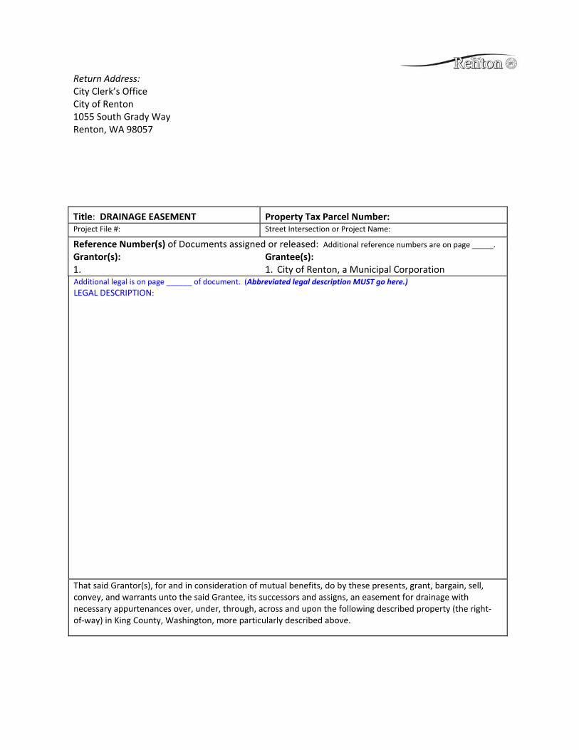
Return Address: City Clerk’s Office City of Renton 1055 South Grady Way Renton, WA 98057
Title: DRAINAGE EASEMENT Property Tax Parcel Number: Project File #: Street Intersection or Project Name:
Reference Number(s) of Documents assigned or released: Additional reference numbers are on page _____. Grantor(s): Grantee(s): 1. 1. City of Renton, a Municipal Corporation Additional legal is on page ______ of document. (Abbreviated legal description MUST go here.) LEGAL DESCRIPTION:
That said Grantor(s), for and in consideration of mutual benefits, do by these presents, grant, bargain, sell, convey, and warrants unto the said Grantee, its successors and assigns, an easement for drainage with necessary appurtenances over, under, through, across and upon the following described property (the right‐of‐way) in King County, Washington, more particularly described above.
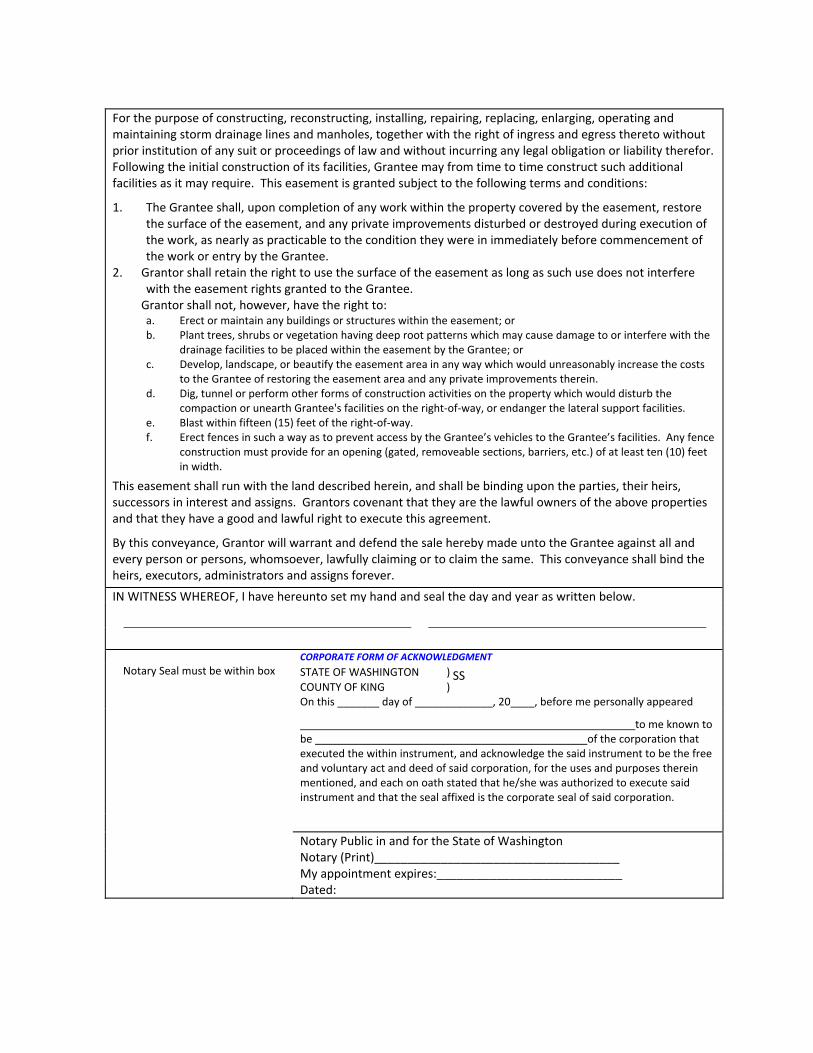
For the purpose of constructing, reconstructing, installing, repairing, replacing, enlarging, operating and maintaining storm drainage lines and manholes, together with the right of ingress and egress thereto without prior institution of any suit or proceedings of law and without incurring any legal obligation or liability therefor. Following the initial construction of its facilities, Grantee may from time to time construct such additional facilities as it may require. This easement is granted subject to the following terms and conditions:
1. The Grantee shall, upon completion of any work within the property covered by the easement, restore the surface of the easement, and any private improvements disturbed or destroyed during execution of the work, as nearly as practicable to the condition they were in immediately before commencement of the work or entry by the Grantee.
2. Grantor shall retain the right to use the surface of the easement as long as such use does not interfere with the easement rights granted to the Grantee.
Grantor shall not, however, have the right to: a. Erect or maintain any buildings or structures within the easement; or b. Plant trees, shrubs or vegetation having deep root patterns which may cause damage to or interfere with the
drainage facilities to be placed within the easement by the Grantee; or c. Develop, landscape, or beautify the easement area in any way which would unreasonably increase the costs
to the Grantee of restoring the easement area and any private improvements therein. d. Dig, tunnel or perform other forms of construction activities on the property which would disturb the
compaction or unearth Grantee's facilities on the right‐of‐way, or endanger the lateral support facilities. e. Blast within fifteen (15) feet of the right‐of‐way. f. Erect fences in such a way as to prevent access by the Grantee’s vehicles to the Grantee’s facilities. Any fence
construction must provide for an opening (gated, removeable sections, barriers, etc.) of at least ten (10) feet in width.
This easement shall run with the land described herein, and shall be binding upon the parties, their heirs, successors in interest and assigns. Grantors covenant that they are the lawful owners of the above properties and that they have a good and lawful right to execute this agreement.
By this conveyance, Grantor will warrant and defend the sale hereby made unto the Grantee against all and every person or persons, whomsoever, lawfully claiming or to claim the same. This conveyance shall bind the heirs, executors, administrators and assigns forever.
IN WITNESS WHEREOF, I have hereunto set my hand and seal the day and year as written below.
CORPORATE FORM OF ACKNOWLEDGMENT Notary Seal must be within box STATE OF WASHINGTON ) SS
COUNTY OF KING ) On this _______ day of _____________, 20____, before me personally appeared
to me known to be of the corporation that executed the within instrument, and acknowledge the said instrument to be the free and voluntary act and deed of said corporation, for the uses and purposes therein mentioned, and each on oath stated that he/she was authorized to execute said instrument and that the seal affixed is the corporate seal of said corporation.
Notary Public in and for the State of Washington Notary (Print)_____________________________________ My appointment expires:____________________________ Dated:

Exhibit A
Legal Description
Project: WO# PID GRANTOR: Street:

Map Exhibit
2009 Surface Water Design Manual Amendment City of Renton
CITY OF RENTON AMENDMENTS TO THE KING COUNTY
SURFACE WATER DESIGN MANUAL
REFERENCE 8-M FLOW CONTROL BMP COVENANT

RECORDING REQUESTED BY AND WHEN RECORDED MAIL TO: CITY CLERK’S OFFICE
CITY OF RENTON
1055 SOUTH GRADY WAY
RENTON, WA 98057
DECLARATION OF COVENANT FOR MAINTENANCE AND INSPECTION OF FLOW CONTROL BMPS
Grantor:
Grantee: City of Renton
Legal Description:
Additional Legal(s) on:
Assessor's Tax Parcel ID#:
IN CONSIDERATION of the approved City of Renton(check one of the following) residential
building permit, commercial building permit, clearing and grading permit, subdivision permit, or
short subdivision permit for Application File No. LUA/SWP ____________________ relating to the
real property ("Property") described above, the Grantor(s), the owner(s) in fee of that Property, hereby
covenants(covenant) with City or Renton, a political subdivision of the state of Washington, that
he/she(they) will observe, consent to, and abide by the conditions and obligations set forth and described
in Paragraphs 1 through 8 below with regard to the Property. Grantor(s) hereby grants(grant),
covenants(covenant), and agrees(agree) as follows:
1. Grantor(s) or his/her(their) successors in interest and assigns ("Owners") shall retain, uphold,
and protect the stormwater management devices, features, pathways, limits, and restrictions, known as
flow control best management practices ("BMPs"), shown on the approved Flow Control BMP Site Plan
for the Property attached hereto and incorporated herein as Exhibit A.
2. The Owners shall at their own cost, operate, maintain, and keep in good repair, the Property's
BMPs as described in the approved Design and Maintenance Details for each BMP attached hereto and
incorporated herein as Exhibit B.
3. City or Renton shall provide at least 30 days written notice to the Owners that entry on the
Property is planned for the inspection of the BMPs. After the 30 days, the Owners shall allow the City of
Renton to enter for the sole purpose of inspecting the BMPs. In lieu of inspection by the City, the
Owners may elect to engage a licensed civil engineer registered in the state of Washington who has
expertise in drainage to inspect the BMPs and provide a written report describing their condition. If the
engineer option is chosen, the Owners shall provide written notice to the City of Renton within fifteen
days of receiving the City's notice of inspection. Within 30 days of giving this notice, the Owners, or the
engineer on behalf of the Owners, shall provide the engineer's report to the City of Renton. If the report
is not provided in a timely manner as specified above, the County may inspect the BMPs without further
notice.
4. If the City determines from its inspection, or from an engineer's report provided in accordance
with Paragraph 3, that maintenance, repair, restoration, and/or mitigation work is required for the BMPs,
The City shall notify the Owners of the specific maintenance, repair, restoration, and/or mitigation work
(Work) required under RMC 4-6-030. The City shall also set a reasonable deadline for completing the
Work or providing an engineer's report that verifies completion of the Work. After the deadline has

passed, the Owners shall allow the City access to re-inspect the BMPs unless an engineer's report has
been provided verifying completion of the Work. If the work is not completed properly within the time
frame set by the City, the City may initiate an enforcement action. Failure to properly maintain the BMPs
is a violation of RMC 4-6-030 and may subject the Owners to enforcement under the RMC 1-3, including
fines and penalties.
5. Apart from performing routine landscape maintenance, the Owners are hereby required to
obtain written approval from the City or Renton before performing any alterations or modifications to the
BMPs.
6. Any notice or approval required to be given by one party to the other under the provisions of
this Declaration of Covenant shall be effective upon personal delivery to the other party, or after three (3)
days from the date that the notice or approval is mailed with delivery confirmation to the current address
on record with each Party. The parties shall notify each other of any change to their addresses.
7. This Declaration of Covenant is intended to promote the efficient and effective management of
surface water drainage on the Property, and it shall inure to the benefit of all the citizens of the City of
Renton and its successors and assigns. This Declaration of Covenant shall run with the land and be
binding upon Grantor(s), and Grantor's(s') successors in interest and assigns.
8. This Declaration of Covenant may be terminated by execution of a written agreement by the
Owners and the City of Renton that is recorded by King County in its real property records.
IN WITNESS WHEREOF, this Declaration of Covenant for the Maintenance and Inspection of
Flow Control BMPs is executed this _____ day of ____________________, 20_____.
GRANTOR, owner of the Property
GRANTOR, owner of the Property
STATE OF WASHINGTON ) COUNTY OF KING )ss.
On this day personally appeared before me: , to me known to be the individual(s) described in and who executed the within and foregoing instrument and acknowledged that they signed the same as their free and voluntary act and deed, for the uses and purposes therein stated.
Given under my hand and official seal this _____ day of ____________________, 20_____.
Printed name Notary Public in and for the State of Washington, residing at
My appointment expires
2009 Surface Water Design Manual Amendment City of Renton
CITY OF RENTON AMENDMENTS TO THE KING COUNTY
SURFACE WATER DESIGN MANUAL
REFERENCE 8-N IMPERVIOUS SURFACE LIMIT COVENANT


RECORDING REQUESTED BY AND WHEN RECORDED MAIL TO: CITY CLERK’S OFFICE
CITY OF RENTON
1055 SOUTH GRADY WAY
RENTON, WA 98057
DECLARATION OF COVENANT FOR IMPERVIOUS SURFACE LIMIT
Grantor: _
Grantee: City of Renton
Legal Description:
_________________________________________________________________________________
_________________________________________________________________________________
Additional Legal(s) on:
Assessor's Tax Parcel ID#:
IN CONSIDERATION of the approved City of Renton ________________________ permit for
application file No. LUA/SWP relating to real property legally described
above, the undersigned as Grantor(s), declares(declare) that the above described property is hereby
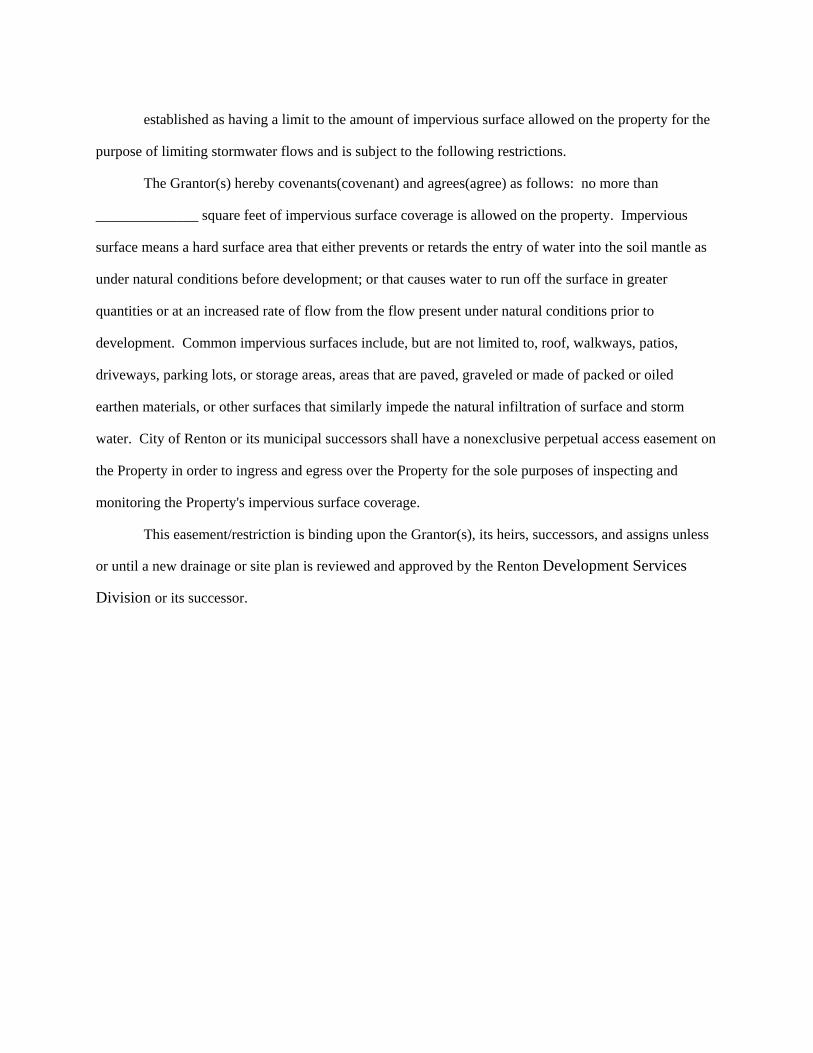
established as having a limit to the amount of impervious surface allowed on the property for the
purpose of limiting stormwater flows and is subject to the following restrictions.
The Grantor(s) hereby covenants(covenant) and agrees(agree) as follows: no more than
______________ square feet of impervious surface coverage is allowed on the property. Impervious
surface means a hard surface area that either prevents or retards the entry of water into the soil mantle as
under natural conditions before development; or that causes water to run off the surface in greater
quantities or at an increased rate of flow from the flow present under natural conditions prior to
development. Common impervious surfaces include, but are not limited to, roof, walkways, patios,
driveways, parking lots, or storage areas, areas that are paved, graveled or made of packed or oiled
earthen materials, or other surfaces that similarly impede the natural infiltration of surface and storm
water. City of Renton or its municipal successors shall have a nonexclusive perpetual access easement on
the Property in order to ingress and egress over the Property for the sole purposes of inspecting and
monitoring the Property's impervious surface coverage.
This easement/restriction is binding upon the Grantor(s), its heirs, successors, and assigns unless
or until a new drainage or site plan is reviewed and approved by the Renton Development Services
Division or its successor.
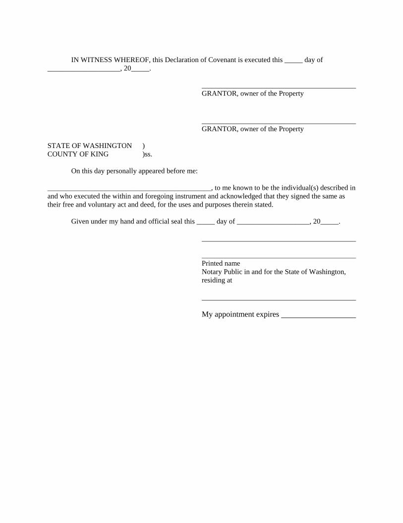
IN WITNESS WHEREOF, this Declaration of Covenant is executed this _____ day of ____________________, 20_____.
GRANTOR, owner of the Property
GRANTOR, owner of the Property
STATE OF WASHINGTON ) COUNTY OF KING )ss.
On this day personally appeared before me: _____________________________________________, to me known to be the individual(s) described in and who executed the within and foregoing instrument and acknowledged that they signed the same as their free and voluntary act and deed, for the uses and purposes therein stated. Given under my hand and official seal this _____ day of ____________________, 20_____.
Printed name Notary Public in and for the State of Washington, residing at My appointment expires

2009 Surface Water Design Manual Amendment City of Renton
CITY OF RENTON AMENDMENTS TO THE KING COUNTY
SURFACE WATER DESIGN MANUAL
REFERENCE 8-O CLEARING LIMIT COVENANT

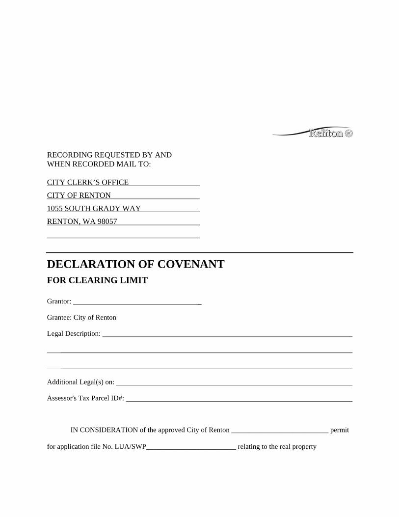
RECORDING REQUESTED BY AND WHEN RECORDED MAIL TO: CITY CLERK’S OFFICE
CITY OF RENTON
1055 SOUTH GRADY WAY
RENTON, WA 98057
DECLARATION OF COVENANT FOR CLEARING LIMIT
Grantor: _
Grantee: City of Renton
Legal Description:
_________________________________________________________________________________
_________________________________________________________________________________
Additional Legal(s) on:
Assessor's Tax Parcel ID#:
IN CONSIDERATION of the approved City of Renton ___________________________ permit
for application file No. LUA/SWP_________________________ relating to the real property
("Property") described above, the Grantor(s), the owner(s) in fee of that Property, hereby declares
(declare) that the Property is established as having a native growth retention area for the purpose of
dispersing and treating stormwater flows and is subject to restrictions applying to vegetation removal in
all designated areas shown in Exhibit A attached hereto, and hereby covenants (covenant) and agrees
(agree) as follows:
1. Any alterations to critical areas, their buffers, and native growth retention areas shall be
pursuant to applicable Renton Municipal Code.
2. The property within the native growth protection area (shown in Attachment A) shall be
maintained in a forested condition, with the exception of open water and existing non-forested native
wetland plant communities. The following activities are allowed and must be done in a manner that
maintains forested hydrologic conditions and soil stability:
a. Removal of noxious weeds and non-native vegetation using hand equipment, provided that
those areas are replanted with appropriate native vegetation.
b. Removal of dangerous and diseased trees.
c. Passive recreation and related activities including trails, nature viewing, fishing, camping
areas, and other similar activities that do not require permanent structures, provided that cleared areas and
areas of compacted soil associated with these areas and facilities do not exceed eight percent of the native
growth retention area.
d. The native growth retention area may contain utilities and utility easements including flow
control BMPs, but not including septic systems.
e. Limited trimming and pruning of vegetation for the creation and maintenance of views per
applicable Renton Municipal Code.
f. Timber harvest in accordance with the City of Renton Tree Clearing and Land
Regulations, the Department of Natural Resources forest practices permit, and if applicable, the City of
Renton Urban Separator Overlay Regulations.
3. City of Renton shall have a nonexclusive perpetual access easement on the Property in order
to ingress and egress over the Property for the sole purposes of inspecting and monitoring the Property's
native growth retention area.
4. This easement/restriction is binding upon the Grantor(s), his/her (their) heirs, successors and
assigns unless or until a new drainage or site plan is reviewed and approved by the the City of Renton or
its successor.
IN WITNESS WHEREOF, this Declaration of Covenant is executed this _____ day of ____________________, 20_____.
GRANTOR, owner of the Property
GRANTOR, owner of the Property
STATE OF WASHINGTON )
COUNTY OF KING )ss.
On this day personally appeared before me:
, to me known to be the individual(s) described in and who executed the within and foregoing instrument and acknowledged that they signed the same as their free and voluntary act and deed, for the uses and purposes therein stated.
Given under my hand and official seal this _____ day of ____________________, 20_____.
Printed name
Notary Public in and for the State of Washington, residing at
My appointment expires
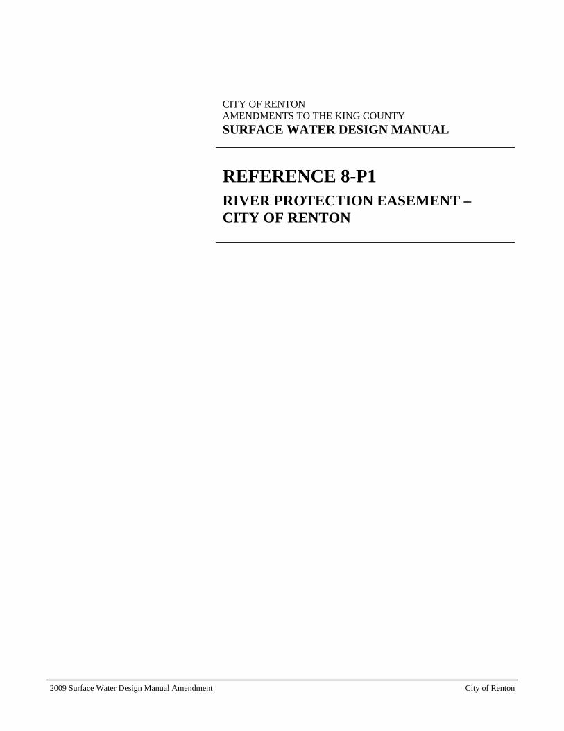
2009 Surface Water Design Manual Amendment City of Renton
CITY OF RENTON AMENDMENTS TO THE KING COUNTY
SURFACE WATER DESIGN MANUAL
REFERENCE 8-P1 RIVER PROTECTION EASEMENT – CITY OF RENTON

RETURN ADDRESS: CITY CLERK’S OFFICE CITY OF RENTON 1055 SOUTH GRADY WAY RENTON, WA 98057
Document Title: River Protection Easement Reference Number of Related Document: Grantor(s): Grantee(s): City of Renton Legal Description: Assessor’s Tax Parcel Number:
RIVER PROTECTION EASEMENT For valuable consideration, receipt of which is hereby acknowledged, the GRANTOR(S), owner(s) in fee of that certain parcel of land (the “Property”), legally described as follows: ____________________________________________________________________________________________________________________________________________________________________________________________________________________________________________________________________________________________________________________________ hereby grant(s) to CITY OF RENTON, a political subdivision of the State of Washington , its successors and assigns, agents and licensees (GRANTEE), a perpetual easement for the purposes of accessing and constructing, inspecting, monitoring, reconstructing, maintaining, repairing, modifying, and removing river bank protection and/or other flood related works, including installing, inspecting, maintaining and removing all vegetation and any other appurtenances thereto across, in, under, on, over and upon the following portions of the above described Property: All portions of the above described parcel that are riverward of a line that is
parallel to and thirty (30) feet landward of the stable top of the river bank on the _________ River (“Easement Area”), as constructed or reconstructed, together with reasonable ingress and egress upon the Property to access the Easement Area.
Grantee shall have the right at such time as may be necessary and at the Grantee’s sole discretion, to enter upon the Property and to have unimpeded access to, in and through the Easement Area for the purposes of exercising the Grantee’s rights as described herein. Grantor agrees not to plant non-native vegetation within the Easement Area and not to remove or otherwise alter any improvements installed by Grantee, including any native vegetation that may be planted and any flood protection works that may be constructed, within the Easement Area, without the prior approval of Grantee. Grantor further agrees not to use herbicides within the Easement Area without the prior approval of Grantee. Nothing contained herein shall be construed as granting any license, permit or right, otherwise required by law, to Grantor with respect to the Property and the Easement Area. For the purposes of this river protection easement, the term “native vegetation” shall mean vegetation comprised of plant species, other than noxious weeds (as identified on the State of Washington noxious weed list found at Washington Administrative Code Chapter 16-750, as amended from time to time), which are indigenous to the coastal region of the Pacific Northwest and which reasonably could have been expected to naturally occur at the site. Neither Grantor nor Grantee is hereby obligated to future maintenance, repair or other action related to the above-described exercise of easement rights. This river protection easement and/or any flood related works constructed or to be constructed within the Easement Area shall not be construed as granting any rights to any third person or entity, or as a guarantee of any protection from flooding or flood damage, and nothing contained herein shall be construed as waiving any immunity to liability granted to Grantee by any state statute, including Chapter 86.12 of the Revised Code of Washington, or as otherwise granted or provided for by law.
The rights, conditions, and provisions of this easement shall inure to the benefit of and be binding upon the heirs, executors, administrators, and successors in interest and assigns of Grantor and Grantee. GRANTOR GRANTOR STATE OF WASHINGTON ) ) ss. COUNTY OF KING ) On this _______ day of ____________, 20___, before me, the undersigned, a Notary Public in and for the State of Washington, duly commissioned and sworn, personally appeared _______________________, to me known to be the individual described in and who executed the foregoing instrument, and acknowledged to me that he/she signed and sealed the said instrument as ______ free and voluntary act and deed for the uses and purposes therein mentioned. Given under my hand and official seal the ________ day of ______________, 20___. NOTARY PUBLIC in and for the State of Washington, residing at My commission expires J\mi20-easement

2009 Surface Water Design Manual Amendment City of Renton
CITY OF RENTON AMENDMENTS TO THE KING COUNTY
SURFACE WATER DESIGN MANUAL
REFERENCE 8-Q LEACHABLE METALS COVENANT

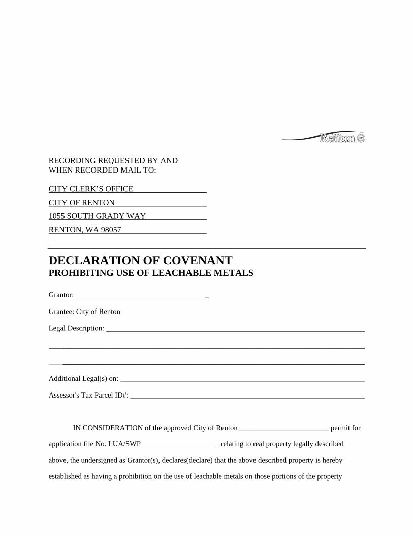
RECORDING REQUESTED BY AND WHEN RECORDED MAIL TO: CITY CLERK’S OFFICE
CITY OF RENTON
1055 SOUTH GRADY WAY
RENTON, WA 98057
DECLARATION OF COVENANT PROHIBITING USE OF LEACHABLE METALS
Grantor: _
Grantee: City of Renton
Legal Description:
_________________________________________________________________________________
_________________________________________________________________________________
Additional Legal(s) on:
Assessor's Tax Parcel ID#:
IN CONSIDERATION of the approved City of Renton ________________________ permit for
application file No. LUA/SWP relating to real property legally described
above, the undersigned as Grantor(s), declares(declare) that the above described property is hereby
established as having a prohibition on the use of leachable metals on those portions of the property
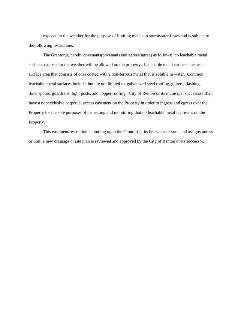
exposed to the weather for the purpose of limiting metals in stormwater flows and is subject to
the following restrictions.
The Grantor(s) hereby covenants(covenant) and agrees(agree) as follows: no leachable metal
surfaces exposed to the weather will be allowed on the property. Leachable metal surfaces means a
surface area that consists of or is coated with a non-ferrous metal that is soluble in water. Common
leachable metal surfaces include, but are not limited to, galvanized steel roofing, gutters, flashing,
downspouts, guardrails, light posts, and copper roofing. City of Renton or its municipal successors shall
have a nonexclusive perpetual access easement on the Property in order to ingress and egress over the
Property for the sole purposes of inspecting and monitoring that no leachable metal is present on the
Property.
This easement/restriction is binding upon the Grantor(s), its heirs, successors, and assigns unless
or until a new drainage or site plan is reviewed and approved by the City of Renton or its successor.

IN WITNESS WHEREOF, this Declaration of Covenant is executed this _____ day of ____________________, 20_____.
GRANTOR, owner of the Property
GRANTOR, owner of the Property
STATE OF WASHINGTON ) COUNTY OF KING )ss.
On this day personally appeared before me: _____________________________________________, to me known to be the individual(s) described in and who executed the within and foregoing instrument and acknowledged that they signed the same as their free and voluntary act and deed, for the uses and purposes therein stated. Given under my hand and official seal this _____ day of ____________________, 20_____.
Printed name Notary Public in and for the State of Washington, residing at My appointment expires

2009 Surface Water Design Manual Amendment City of Renton
CITY OF RENTON AMENDMENTS TO THE KING COUNTY
SURFACE WATER DESIGN MANUAL
REFERENCE 11 REFERENCE MAPS
11-A Flow Control Application Map
11-B Aquifer Protection Areas
11-C Soil Survey Map
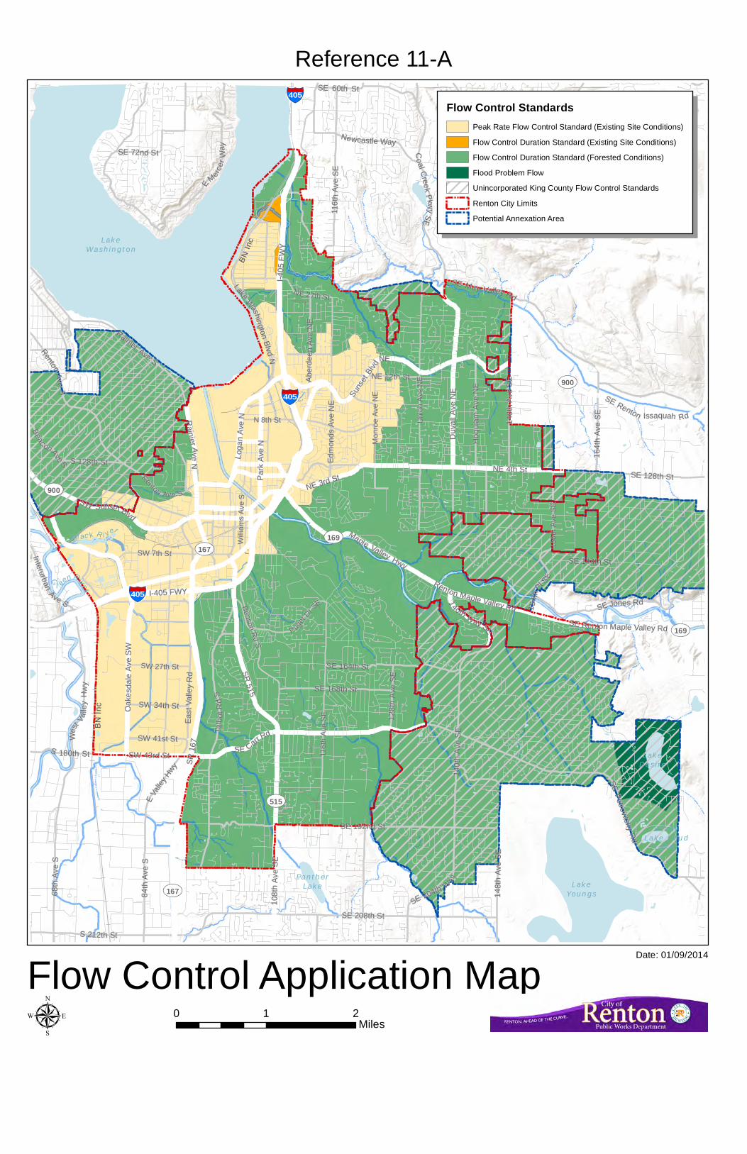
LakeDesire
ShadyLake (Mud
Lake)
PantherLake Lake
Youngs
LakeWashington
Bl ac k R i ver
G
r eenRiver C edar R i v er
UV900
UV167
UV515
UV169
UV900
UV169
UV167
BN
Inc
BN
Inc
BBNN
IInncc
SSEE RReennttoonn IIssssaaqquuaahh RRdd
RReenn ttoonn MMaappllee VVaalllleeyy RRdd
MMaappll ee VVaall lleeyy HHwwyy
1 10 08 8t t
h hA A
v ve eS S
E E
SSWW SSuunnsseett BBllvvdd
RRaa ii nn ii ee rr AAvv ee
NN
NE 3rd StNE 3rd St
SW 43rd StSW 43rd StSSEE CCaarrrr RR
dd
NE 4th StNE 4th St
SSEE RReennttoonn MMaappllee VVaalllleeyy RRdd
LLooggaa
nnAA
v veeNN
SR 515
SR 515
P Pa ar r
k kA A
v ve eN N
O Oa ak k
e es sd da a
l le eA A
v ve eS S
W W
SSuunnss
eettBBll
vvdd
NNEE
DDu uv v
a al ll lA A
v ve eN N
E E
I-405 FWYI-405 FWY
I I- -440055
FFWW
YY
SR 1
67SR
167
11 4400tthh WWaayy SSEE
NN EE 2277tthh SStt
1 15 56 6t t
h hA A
v ve eS S
E E
U Un ni i
o on nA A
v ve eN N
E E
1 11 16 6t t
h hA A
v ve eS S
E E
SW 7th StSW 7th St
N 8th StN 8th St
PPuuggeett
DDrr SSEE
RReenn tt oo nn AAvvee SS
SSWW 2277tthh SStt
BBee nn ss oo nn
RRdd
SS
W Wi il ll l
i ia am m
s sA A
v ve eS S
M Mo on n
r ro oe e
A Av ve e
N NE E
SE 128th StSE 128th St
II nn tt ee rr uu rr bb aa nnAA vvee SS
H Ho oq q
u ui ia am m
A Av ve e
N NE E
8 84 4t th h
A Av ve e
S SSS EE
PP ee tt rr oo vv ii tt ss kk yyRR
dd
EEVVaa
lllleeyy
HHwwyy
SE 192nd StSE 192nd St
SE 60th StSE 60th St
TTaal lbb
o ot tR R
ddSS
RReenn ttoo nnAA vvee
SS
1 16 64 4t t
h hA A
v ve eS S
E E
SE 208th StSE 208th St
SE 72nd StSE 72nd St
RRaaiinn iieerr AAvvee SS
1 11 16 6t t
h hA A
v ve eS S
E E
S 128th StS 128th St
NNeewwccaassttllee WWaayy
SS 221122tthh SStt
SS 118800tthh SStt
CCoo aa ll CC
rr ee ee kkPP kk ww
yySSEE
SW 41st StSW 41st St
114 40 0t t
h hA A
v ve eS S
E E
1 12 28 8t t
h hA A
v ve eS S
E E
6 68 8t th h
A Av ve e
S S
SSEE 116688tthh SStt
NE 12th StNE 12th St
BBee aa cc oonn AAvvee SS
FFoorreesstt DDrr SSEE
SSEE 116644tthh SStt
1 14 48 8t t
h hA A
v ve eS S
E E
SSEE MMaayy VVaalllleeyy RRdd
SSEE JJoonneess RRdd
SSEE 220044tthh WW
aayy
SW 34th StSW 34th St
SE 144th StSE 144th St
1 14 48 8t t
h hA A
v ve eS S
E E
115544tt
hhPPll SS
EE
LLaakkeeWW
aass hh ii nn gg tt oo nnBB ll vv dd
NN
E Ed dm m
o on nd ds s
A Av ve e
N NE E
A Ab be e
r rd de ee e
n nA A
v ve eN N
E E
EE
MMeerrccee
rrWW
aay y
W Weess
tt VVaal ll le e
y yH H
w wy y
East
Val
ley
Rd
East
Val
ley
Rd
,§-405
,§-405
,§-405
µ 0 1 2Miles
Flow Control Application Map
Reference 11-A
Date: 01/09/2014
Flow Control StandardsPeak Rate Flow Control Standard (Existing Site Conditions)
Flow Control Duration Standard (Existing Site Conditions)
Flow Control Duration Standard (Forested Conditions)
Flood Problem Flow
Unincorporated King County Flow Control Standards
Renton City Limits
Potential Annexation Area
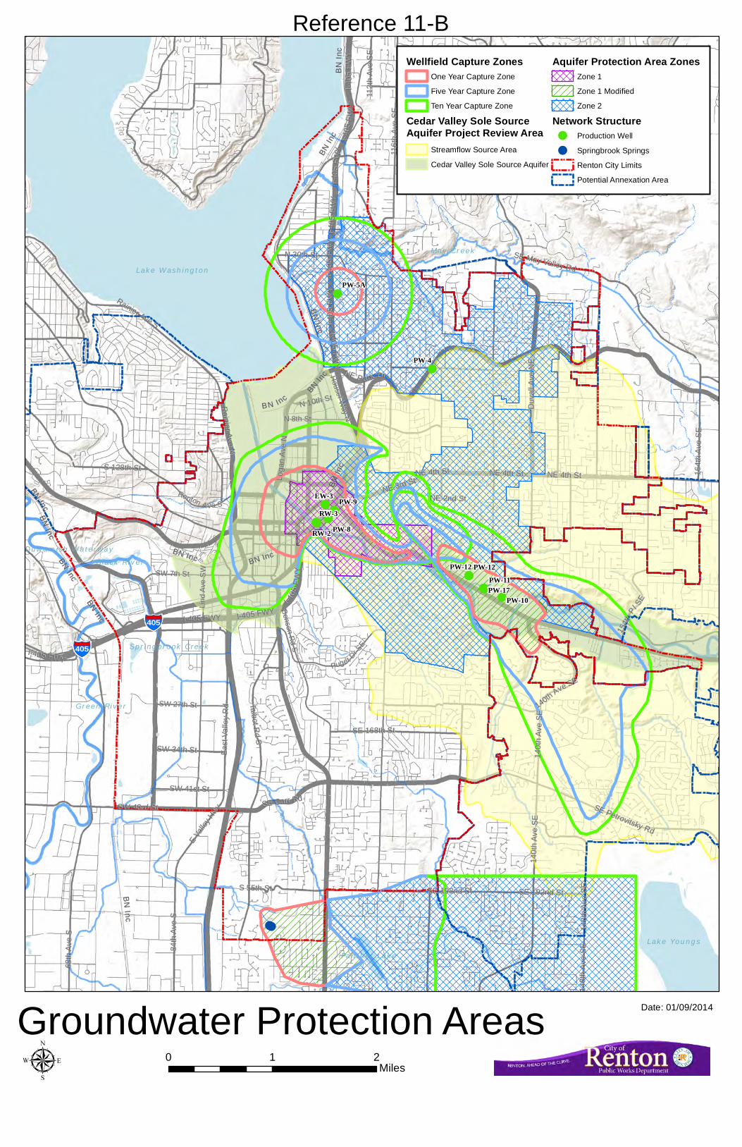
!!!
!
!
!!! !!
!
!
!!
!
!
!!!
!!
PW-12PW-11PW-17
PW-4
PW-9
PW-8RW-3
RW-2
EW-3
PW-5A
PW-12
PW-10
,§-405
,§-405
115544tt
hhPPll
SSEE
SW 34th StSW 34th St East
Val
ley
Rd
East
Val
ley
Rd
1 14 48 8t t
h hA A
v ve eS S
E E
140t
h Av
e SE
140t
h Av
e SE
164t
h Av
e SE
164t
h Av
e SE
Talbot Rd S
Talbot Rd S
N 30th StN 30th St
68th
Ave
S68
th A
ve S
Rainier Ave S
Rainier Ave S
SE 192nd StSE 192nd St
SE May Valley Rd
SE May Valley Rd
E Va
lley H
wy
E Va
lley H
wy SE Petrovitsky Rd
SE Petrovitsky Rd
Forest Dr SEForest Dr SE
S 128th StS 128th St
112t
h Av
e S
E11
2th
Ave
SE
84th
Ave
S84
th A
ve S
SE 168th StSE 168th St
S 55th StS 55th St
N 10th StN 10th St
NE 2nd StNE 2nd St
SW 41st StSW 41st St
116t
h Av
e S
E11
6th
Ave
SE
140t
h Av
e SE
140t
h Av
e SE
SE 192nd StSE 192nd St
148t
h Av
e SE
148t
h Av
e SE
114400tthhAAvvee SSEE
SW 27th StSW 27th St
Benson Rd S
Benson Rd S
Houser W
ay N
Houser W
ay N
Lind
Ave
SW
Lind
Ave
SW
N 8th StN 8th St
PPuuggee tt DDrr SSEE
RReennttoonn AA vvee SS
SW 7th StSW 7th St
I-405
FW
YI-4
05 F
WY
Rainier Ave N
Rainier Ave N
NNEE PP aarrkk DDrr
NE 4th StNE 4th St
SW 43rd StSW 43rd St SE Carr RdSE Carr Rd
NE 3rd StNE 3rd StLo
gan
Ave
NLo
gan
Ave
N
Duv
all A
ve N
ED
uval
l Ave
NE
I-405
FW
YI-4
05 F
WY
I-405 FWY
I-405 FWY
I-405 FWYI-405 FWY
I-405
FW
YI-4
05 F
WY
NE 4th StNE 4th St
I-405
FW
YI-4
05 F
WY
II--4400
55FF
WWY Y
I-405
FW
YI-4
05 F
WY
I-405 FWYI-405 FWY
I-405
FW
YI-4
05 F
WY
I-405 FWYI-405 FWY
NE 4th StNE 4th St
BN
IncB
N Inc
BN Inc
BN Inc
BN IncBN Inc
BN Inc
BN Inc
BN IncBN Inc
BN
Inc
BN
Inc
BN IncBN Inc
BN
IncB
N Inc
BB NN IInncc
BN IncBN Inc
BN In
cBN
Inc
BN IncBN Inc
BN In
cBN
Inc
Cedar River
Green River
Black River
May Creek
Duwamish Waterway
Springbrook Creek
Lake Washington
Lake YoungsPanther Lake
Lake Boren
Reference 11-BWellfield Capture Zones
One Year Capture Zone
Five Year Capture Zone
Ten Year Capture Zone
Cedar Valley Sole SourceAquifer Project Review Area
Streamflow Source Area
Cedar Valley Sole Source Aquifer
Aquifer Protection Area ZonesZone 1
Zone 1 Modified
Zone 2
Network Structure! Production Well
! Springbrook Springs
Renton City Limits
Potential Annexation Area
Groundwater Protection Areas Date: 01/09/2014
µ 0 1 2Miles

BeDBeD
BeC
AkF
AmC
KpD
AmB
AmB
AgC
AgC
AgCKpB
AgC
AkF
BeD
AgC
KpD
AgCKpBKpB AgDEvC
Bh BeC
AgB
KpBAgD UrEwC
EvB
AmC
Or
AgC
BeC
BeD
BeDBeC
AgC
KpD
BeC
KpCKpBSk
AmC BeC UrBeC Ur
AgD
KpBUr
AgC
EvCKpC
AgCOvD
SkAgB
AgB
AgD
EvCW
OvD
OvD
NoAgC
AgD
EvCRdC Sk
KpB
No
AgCRdEAgC EvC
BeC
InC
Bh
BeDRdC
AkF
AgDBeD
BhSm
AgC
RdEAgC AgDEvC
Sh
ShPITS
PyAgC
AgD
AgC EvC
PITSEvB
BeC
OvC
PITS
EvB AgCInAAgD
AgD
Ur
Bh
AgC
RdCEvC EvD
AmBAmC
AgDBeD
EvC
AkF
AgDAgC
Sm
AgD
AmC
EvB
AgD
Sm
AgC
EwC
PITSPu
BhBh
AgC
KpD
Tu
AgC
EvC
EvC
Ur
RdC
KpB
RdCRdE
W
AgD
AgD
No
AgB
AgC
No
An
AkF
EvBInD
AgDEvD
InCSk
BeC
PITS
UrWBeC W
BeDAn EvC
BeC
Pc EvC
RhAmC
BeCBeD BeD
Ur
BeC
Ur
W
W
Rh EvC
AkF
PITS
AgD
AmCPITSWo
Py
Tu
BeD
EvB
Py
AmC
PyAn
InC
Ng
AgC
AgC
W
EvB
AgD
AgCWo
Ur W
Ur RdC
Ur
Ur
EvC
Rh
Pc
PyPy
AgD
AmC
AgD MaRh
Pc
BeD PyNg AmC Ng
BeC
AgC
Rh
AgD
PyMa PyRh Rh
RhPu
Pu
UrPu
PITS
BeDRh
EvC
PyWo
Wo
AgC MaAgD
AgB
So
Ng
AgD
TuPy
AgC
AgC
AgC
AgC
Ng Ur
AgD
Sk AmB
AgB
AgDPuUr
Py
Sk
Ur
No
AgB
MaBeCW
AkFBeDPu
Py
NoNo
AmC
AgCEvC
Ma
Sk
EvC AgB
Py
InC SkAmCAmC
AgC
AgB SkAgBPITS
AgC
No
Pu AmB
EvC
PITS
AmB
AgB
AkFAkF
Ng
AgD
AgD
AgB
EvBAmBAmC
AmCWo
Ng
PITS
Nk AgDSkNk SkAgB
Ur AgD
WoAmC No
AgD
NoUr
AgB
UrBr
PyOs So
EvB
Ur
Nk WoAmB
WPc
OsRe
UrAmB
Sk
W
AmC
TuNo
Pu AgD AmBAkF AgC NoUrPk
AgB
AgC
Ur
AmBNoAmC
NoAmC
AmB PITS UrSk AgCAgB
AgC
Re
AgB
WInC No
AgC
Wo
EvC NoAmCWo
AgB
AgB
UrNg SkAmB
ReOs AgCNo
AgD
No
UrNo
InC
AgD EvC
Tu
AmB EvB
AgD
Pu InCEvCAmC NoEvC
UrEvB AkF
Br
Os
AgDAmC
AgB
AgDAmB
Os
OsNoAmC
Pk AkF NoAmC
EvCNoNo
AgDBr AgBAgCAgBAmC
Re ReKpBAmB NoPy Py SkNg AgB EvC
EvC Sk NoEvBNoPu BrPuOsOs Wo AmC
PantherLake
LakeYoungs
LakeWashington
Bl ac k R i ver
Gree n R i v er
Ced a r R ive
r
Duwam i sh Water w a y
UV167
UV900
UV515
UV169
UV900
UV167
BN
Inc
BN
Inc
BBNN
IInncc
SSEE RReenntt oonn IIssssaa qq uu aahh RRdd
S 2nd StS 2nd St
RReennttoonn MMaappllee VVaalllleeyy RRdd
MMaapp llee VVaall lleeyy HHwwyy
1 10 08 8t t
h hA A
v ve eS S
E E
MMa ai i
n nA A
v ve eS S
MMaarr tt ii nnLL
KK ii nn gg JJrr WWaayy SSSSWW SSuunnsseett BBll vvdd
RRaa ii nn ii ee rr AAvv ee
NN
NE 3rd StNE 3rd St
II--440055
FFWWYY
SW 43rd StSW 43rd StSSEE CCaarrrr
RRdd
NE 4th StNE 4th St
SS GGrraaddyy WWaayy
SSEE RReennttoonn MMaappllee VVaalllleeyy RRdd
LLo og ga a
nnAA
v ve eNN
SR 515
SR 515
P Pa ar r
k kA A
v ve eN N
BBee nn ss oo nn
DDrr SS
SSuunn
sseett BB
llvvddNN
OOa ak k
e es sd da a
l le eA A
v ve eS S
W W
SSuunnss
eettBBll
vvdd
NNEE
DDu uv v
a al ll lA A
v ve eN N
E E
SR 1
67SR
167
11 4400tthh WWaayy SSEE
WWaattee rrss AAvvee SS
NNEE 2277tthh SStt
HHoouu ss ee rr WWaa yy
NN
1 15 56 6t t
h hA A
v ve eS S
E E
U Un ni i
o on nA A
v ve eN N
E E
1 11 16 6t t
h hA A
v ve eS S
E E
SW 7th StSW 7th St
PPuuggeett
DDrr SSEE
RReenn tt oonn AAvvee SS
GGa ar r
d de en n
A Av ve e
N N
SSWW 2277tthh SStt
BB ee nn ss oo nnRR
ddSS
W Wi il ll l
i ia am m
s sA A
v ve eS S
M Mo on n
r ro oe e
A Av ve e
N NE E
II nn tt ee rr uu rr bb aa nnAA vv ee
SS
H Ho oq q
u ui ia am m
A Av ve e
N NE E
8 84 4t th h
A Av ve e
S S
SSEE PPeettrroovvii tt sskkyy RRdd
SSoouutthhcc ee nntteerr BBllvvdd
EEVVaa
lllleeyy
HHwwyy
SSh ha at t
t tu uc ck k
A Av ve e
S S
RRaaiinn iieerr AAvvee SS
TTaal lbb
o ot tR R
d dSS
RRee nn tt oonnAAvvee
SS1 16 6
4 4t th h
A Av ve e
S SE E
SE 208th StSE 208th St
SSWW LLaannggssttoonn RRdd
SE 72nd StSE 72nd St
SE 128th StSE 128th St
1 12 24 4t t
h hA A
v ve eS S
E E
S 128th StS 128th St
NNeewwccaassttllee WWaayy
SS 221122tthh SStt
SS 118800tthh SStt
CCooaall
CC rr eeee kkPP
kk wwyy
SSEE
SW 41st StSW 41st St
N 30th StN 30th St
Taylor Pl NW
Taylor Pl NW1 14 4
0 0t th h
A Av ve e
S SE E
1 12 28 8t t
h hA A
v ve eS S
E E
1 11 16 6t t
h hA A
v ve eS S
E E
6 68 8t th h
A Av ve e
S S
SSEE 116688tthh SStt
NE 12th StNE 12th St
BBeeaaccoonn AAvv eeSS
FFoorreesstt DDrr SSEE
UUn ni i
o on nA A
v ve eS S
E E
SE 164th StSE 164th St
N Ni il le e
A Av ve e
N NE E
1 14 48 8t t
h hA A
v ve eS S
E E
SSEE MMaayy VVaalllleeyy RRdd
SSEE 220044tthh WWaayy
SW 34th StSW 34th St
SSEE JJoonneess RRdd
SE 144th StSE 144th St
EEMM
eerrcc
eerrWW
aayy
1 14 48 8t t
h hA A
v ve eS S
E E
WW
MM
eerrccee
rr
WWaayy
115544tt
hhPPll
SSEE
E Ed dm m
o on nd ds s
A Av ve e
N NE E
A Ab be e
r rd de ee e
n nA A
v ve eN N
E E
W Weess
tt VVaal ll le e
y yH H
w wy y
East
Val
ley
Rd
East
Val
ley
Rd
,§-405
,§-405
Reference 11-CRenton City Limits
Potential Annexation Area
Groundwater Protection Area Boundary
Aquifer Protection Area Zone 1
Aquifer Protection Area Zone 1 Modified
Soil TypeAgB
AgC
AgD
AkF
AmB
AmC
An
BeC
BeD
Bh
Br
EvB
EvC
EvD
EwC
InA
InC
InD
KpB
KpC
KpD
Ma
Ng
Nk
No
Or
Os
OvC
OvD
PITS
Pc
Pk
Pu
Py
RdC
RdE
Re
Rh
Sh
Sk
Sm
So
Tu
Ur
W
Wo
Date: 01/09/2014
0 1 2Milesµ
Soil Survey