amd, amg, afg - АДАРА ИНЖЕНЕРИНГ · – atex 94/9/eg (amd, amg, afg, relä alr-20/a...
TRANSCRIPT
AMD, AMG, AFG
GRUNDFOS INSTRUCTIONS
Installation and operating instructions
Declaration of ConformityWe Grundfos declare under our sole responsibility that the products AMD, AMG and AFG, to which this declaration relates, are in conformity with the Council Directives on the approximation of the laws of the EC Member States relating to– Machinery (98/37/EC)
Standards used: EN ISO 12100: 2003 and EN 294: 1992.– Electrical equipment designed for use within certain voltage
limits (73/23/EEC)Standards used: EN 60034 and EN 60204.
– Electromagnetic compatibility (89/336/EEC)Standards used: EN 61000-6-2 and EN 61000-6-3.
– ATEX 94/9/EC (AMD, AMG, AFG, relay ALR-20/A Ex)Applies only to products intended for use in potentially explosive environments and equipped with the separate ATEX approval plate and EC-type examination certificate. Further information, see below.
KonformitätserklärungWir Grundfos erklären in alleiniger Verantwortung, dass die Produkte AMD, AMG und AFG, auf die sich diese Erklärung bezieht, mit den fol-genden Richtlinien des Rates zur Angleichung der Rechtsvorschriften der EG-Mitgliedstaaten übereinstimmen– Maschinen (98/37/EG)
Normen, die verwendet wurden: EN ISO 12100: 2003 und EN 294: 1992.
– Elektrische Betriebsmittel zur Verwendung innerhalb bestimm-ter Spannungsgrenzen (73/23/EWG)Normen, die verwendet wurden: EN 60034 und EN 60204.
– Elektromagnetische Verträglichkeit (89/336/EWG)Normen, die verwendet wurden: EN 61000-6-2 und EN 61000-6-3.
– ATEX 94/9/EG (AMD, AMG, AFG, Relais ALR-20/A Ex)Gilt nur für Produkte, die für den Gebrauch in potentiell explosiver Umgebung bestimmt und mit einem separaten ATEX-Typenschild und einem EG-Prüfzeugnis ausgestattet sind. Weitere Informatio-nen, siehe unten.
Déclaration de ConformitéNous Grundfos déclarons sous notre seule responsabilité que les pro-duits AMD, AMG et AFG auxquels se réfère cette déclaration sont conformes aux Directives du Conseil concernant le rapprochement des législations des Etats membres CE relatives à– Machines (98/37/CE)
Standards utilisés: EN ISO 12100: 2003 et EN 294: 1992.– Matériel électrique destiné à employer dans certaines limites
de tension (73/23/CEE)Standards utilisés: EN 60034 et EN 60204.
– Compatibilité électromagnétique (89/336/CEE)Standards utilisés: EN 61000-6-2 et EN 61000-6-3.
– ATEX 94/9/CE (AMD, AMG, AFG, relais ALR-20/A Ex)S'applique uniquement aux pompes utilisées dans des environne-ments potentiellement explosifs équipées d'une plaque séparée avec norme ATEX et d'un certificat d'examination type EC. Pour plus d'informations, voir ci-après.
Dichiarazione di ConformitàNoi Grundfos dichiariamo sotto la nostra esclusiva responsabilità che i prodotti AMD, AMG e AFG ai quali questa dichiarazione se riferisce sono conformi alle Direttive del Consiglio concernente il ravvicinamento delle legislazioni degli Stati membri CE relative a– Macchine (98/37/CE)
Standard usati: EN ISO 12100: 2003 e EN 294: 1992.– Materiale elettrico destinato ad essere utilizzato entro certi
limiti di tensione (73/23/CEE)Standard usati: EN 60034 e EN 60204.
– Compatibilità elettromagnetica (89/336/CEE)Standard usati: EN 61000-6-2 e EN 61000-6-3.
– ATEX 94/9/CE (AMD, AMG, AFG, rele’ ALR-20/A Ex)Si riferisce solo ai prodotti per uso in ambienti potenzialmente esplosivi con targa di approvazone ATEX a parte e certificato tipo EC. Per ulteriori informazioni, vedere oltre.
Declaración de ConformidadNosotros Grundfos declaramos bajo nuestra única responsabilidad que los productos AMD, AMG y AFG a los cuales se refiere esta declaración son conformes con las Directivas del Consejo relativas a la aproxima-ción de las legislaciones de los Estados Miembros de la CE sobre– Máquinas (98/37/CE)
Normas aplicadas: EN ISO 12100: 2003 y EN 294: 1992.– Material eléctrico destinado a utilizarse con determinadas lími-
tes de tensión (73/23/CEE)Normas aplicadas: EN 60034 y EN 60204.
– Compatibilidad electromagnética (89/336/CEE)Normas aplicadas: EN 61000-6-2 y EN 61000-6-3.
– ATEX 94/9/CE (AMD, AMG, AFG, relé ALR-20/A Ex)Se aplica sólo a productos concebidos para su utilización en entor-nos potencialmente explosivos equipados con una placa independiente de homologación ATEX y certificado de prueba tipo EC. Para información adicional, ver más abajo.
Declaração de ConformidadeNós Grundfos declaramos sob nossa única responsabilidade que os produtos AMD, AMG e AFG aos quais se refere esta declaração estão em conformidade com as Directivas do Conselho das Comunidades Europeias relativas à aproximação das legislações dos Estados Mem-bros respeitantes à– Máquinas (98/37/CE)
Normas utilizadas: EN ISO 12100: 2003 e EN 294: 1992.– Material eléctrico destinado a ser utilizado dentro de certos
limites de tensão (73/23/CEE)Normas utilizadas: EN 60034 e EN 60204.
– Compatibilidade electromagnética (89/336/CEE)Normas utilizadas: EN 61000-6-2 e EN 61000-6-3.
– ATEX 94/9/CE (AMD, AMG, AFG, relé ALR-20/A Ex)Aplica-se apenas a produtos cuja utilização é em ambientes poten-cialmente explosivos, Ex II 2G, equipados com uma chapa de aprovação ATEX e certificado tipo EC. Para mais informações con-sulte abaixo.
Product Certificate No Standards used
AMD, AMG, AFG SEV 05 ATEX 0109 XSEV 05 ATEX 0111 X
EN 1127-1: 1997, EN 50014: 1997, EN 50018: 2000, EN 50019: 2000, EN 50020: 2002, EN 13463-1: 2001, EN 13463-5: 2003 and EN 13463-8: 2003.
ALR-20/A Ex SEV 05 ATEX 0131 EN 1127-1: 1997, EN 50014: 1997 and EN 50020: 2002.
Notified body: Electrosuisse. No. 1258. Luppmenstrasse 1, CH-8320 Fehraltorf, Switzerland.Manufacturer: ARNOLD AG, A Grundfos Company, Industrie Nord 12, CH-6105 Schachen, Switzerland.
2
3
Δήλωση ΣυμμόρφωσηςΕμείς η Grundfos δηλώνουμε με αποκλειστικά δική μας ευθύνη ότι τα προιόντα AMD, AMG και AFG συμμορφώνονται με την Οδηγία του Συμβουλίου επί της σύγκλισης των νόμων των Κρατών Mελών της Ευρωπαικής Ενωσης σε σχέση με τα– Μηχανήματα (98/37/EC)
Πρότυπα που χρησιμοποιήθηκαν: EN ISO 12100: 2003 και EN 294: 1992.
– Ηλεκτρικές συσκευές σχεδιασμένες γιά χρήση εντός ορισμένων ορίων ηλεκτρικής τάσης (73/23/EEC)Πρότυπα που χρησιμοποιήθηκαν: EN 60034 και EN 60204.
– Ηλεκτρομαγνητική συμβατότητα (89/336/EEC)Πρότυπα που χρησιμοποιήθηκαν: EN 61000-6-2 και EN 61000-6-3.
– ATEX 94/9/EC (AMD, AMG, AFG, relέ ALR-20/A Ex) Ισχύει μόνο για προϊόντα που απευθύνονται για χρήση σε δυνητικά εκρηκτικά περιβάλλοντα εφοδιασμένα με τη χωριστή πινακίδα έγκρισης ATEX και πιστοποιητικό εξέτασης τύπου EC. Για περισσότερες πληροφορίες, βλέπε κατωτέñù.
OvereenkomstigheidsverklaringWij Grundfos verklaren geheel onder eigen verantwoordelijkheid dat de produkten AMD, AMG en AFG waarop deze verklaring betrekking heeft in overeenstemming zijn met de Richtlijnen van de Raad inzake de onderlinge aanpassing van de wetgevingen van de Lid-Staten betreffende– Machines (98/37/EG)
Normen: EN ISO 12100: 2003 en EN 294: 1992.– Elektrisch materiaal bestemd voor gebruik binnen bepaalde
spanningsgrenzen (73/23/EEG)Normen: EN 60034 en EN 60204.
– Elektromagnetische compatibiliteit (89/336/EEG)Normen: EN 61000-6-2 en EN 61000-6-3.
– ATEX 94/9/EG (AMD, AMG, AFG, relais ALR-20/A Ex)Is alleen van toepassing op pompen welke gebruikt worden in een explosie gevaarlijke omgeving met een afzonderlijke ATEX-goed-keurings plaatje en EC-type onderzoekscertificaat. Voor verdere informatie, zie onderstaand.
Försäkran om överensstämmelseVi Grundfos försäkrar under ansvar, att produkterna AMD, AMG och AFG, som omfattas av denna försäkran, är i överensstämmelse med Rådets Direktiv om inbördes närmande till EU-medlemsstaternas lag-stiftning, avseende– Maskinell utrustning (98/37/EC)
Använda standarder: EN ISO 12100: 2003 och EN 294: 1992.– Elektrisk utrustning avsedd för användning inom vissa
spänningsgränser (73/23/EC)Använda standarder: EN 60034 och EN 60204.
– Elektromagnetisk kompatibilitet (89/336/EC)Använda standarder: EN 61000-6-2 och EN 61000-6-3.
– ATEX 94/9/EG (AMD, AMG, AFG, relä ALR-20/A Ex) Gäller endast produkter avsedda att användas i exposionsfarlig miljö utrustade med separat ATEX-godkännandeskylt och EG-typkontroll-intyg. För ytterligare information, se nedan.
OverensstemmelseserklæringVi Grundfos erklærer under ansvar, at produkterne AMD, AMG og AFG, som denne erklæring omhandler, er i overensstemmelse med Rådets direktiver om indbyrdes tilnærmelse til EF medlemsstaternes lovgivning om– Maskiner (98/37/EF)
Anvendte standarder: EN ISO 12100: 2003 og EN 294: 1992.– Elektrisk materiel bestemt til anvendelse inden for visse
spændingsgrænser (73/23/EØF)Anvendte standarder: EN 60034 og EN 60204.
– Elektromagnetisk kompatibilitet (89/336/EØF)Anvendte standarder: EN 61000-6-2 og EN 61000-6-3.
– ATEX 94/9/EF (AMD, AMG, AFG, relæ ALR-20/A Ex)Gælder kun produkter til eksplosionsfarlige omgivelser med et sepa-rat ATEX-godkendelsesskilt og EF-typeprøvningscertifikat. Yderligere oplysninger, se nedenfor.
Deklaracja zgodnościMy, Grundfos, oświadczamy z pełną odpowiedzialnością, że nasze wyroby AMD, AMG oraz AFG, których deklaracja niniejsza dotyczy, są zgodne z następującymi wytycznymi Rady d/s ujednolicenia przepisów prawnych krajów członkowskich EG:– Maszyny (98/37/EG)
EN ISO 12100: 2003 and EN 294: 1992.– Wyposażenie elektryczne do stosowania w określonym
zakresie napięć (73/23/EWG)Zastosowane normy: EN 60034 i EN 60204,
– Zgodność elektromagnetyczna (89/336/EWG)Zastosowane normy: EN 61000-6-2 i EN 61000-6-3,
– ATEX 94/9/EG (AMD, AMG, AFG, przekaźnik ALR 20/A Ex)Dotyczy tylko produktów przeznaczonych do pracy w środowisku potencjalnie zagrożonym wybuchem wyposażonych w odzielną tabliczkę znamionową ATEX i certyfikat typu EC (examination certyficate) Więcej informacji na ten temat, patrz poni¿ej.
Декларация о соответствииМы, фирма Grundfos, со всей ответственностью заявляем, что изделия AMD, AMG и AFG, к которым и относится данное свидетельство, отвечают требованиям следующих указаний Совета ЕС об унификации законодательных предписаний стран-членов ЕС:– Машиностроение (98/37/ЕС)
Применявшиеся стандарты: EN ISO 12100: 2003 и EN 294: 1992.– Электрические машины для эксплуатации в пределах
определенного диапазона значений напряжения (73/23/ЕЭС)Применявшиеся стандарты: EN 60034 и EN 60204.
– Электромагнитная совместимость (89/336/ЕЭС)Применявшиеся стандарты: Евростандарт EN 61000-6-2 и EN 61000-6-3.
– ATEX 94/9/EC (AMD, AMG, AFG, pеле ALR-20/A Ex)Действительно только для изделий, разрешённых для использования в потенциально взрывоопасных условиях с маркировкой ATEX на фирменной табличке и Сертификатом (свидетельством) типовой проверки ЕС. Подробная информация представлена ниже.
Product Certificate No Standards used
AMD, AMG, AFG SEV 05 ATEX 0109 XSEV 05 ATEX 0111 X
EN 1127-1: 1997, EN 50014: 1997, EN 50018: 2000, EN 50019: 2000, EN 50020: 2002, EN 13463-1: 2001, EN 13463-5: 2003 and EN 13463-8: 2003.
ALR-20/A Ex SEV 05 ATEX 0131 EN 1127-1: 1997, EN 50014: 1997 and EN 50020: 2002.
Notified body: Electrosuisse. No. 1258. Luppmenstrasse 1, CH-8320 Fehraltorf, Switzerland.Manufacturer: ARNOLD AG, A Grundfos Company, Industrie Nord 12, CH-6105 Schachen, Switzerland.

4
Konformitási nyilatkozatMi, a Grundfos, egyedüli felelősséggel kijelentjük, hogy az AMD, AMG és AFG termékek, amelyekre jelen nyilatkozat vonatkozik, megfelelnek az Európai Unió tagállamainak jogi irányelveit összehangoló tanács alábbi irányelveinek:– Gépek (98/37/EK)
Alkalmazott szabványok: EN ISO 12100: 2003 és EN 294: 1992.– Meghatározott feszültség határokon belül használt elektromos
eszközök (73/23/EGK)Alkalmazott szabványok: EN 60034 és EN 60204.
– Elektromágneses összeférhetőség (89/336/EGK)Alkalmazott szabványok: EN 61000-6-2 és EN 61000-6-3.
– ATEX 94/9/EK (AMD, AMG, AFG, ALR-20A Ex relé)Azon szivattyú típusokra vonatkozik, melyek potencionálisan robbanásveszélyes környezetben telepíthetők és el vannak látva egy további ATEX jelzésű adattáblával, valamint rendelkeznek EC típusú vizsgálati bizonylattal is. További információ, lásd lejjebb.
Izjava o ustreznostiMi, Grundfos, pod polno odgovornostjo izjavljamo, da so izdelki AMD, AMG in AFG, na katere se ta izjava nanaša, v skladu z naslednjimi smernicami Sveta za uskladitev pravnih predpisov držav članic Evropske skupnosti:– Stroji (98/37/EG)
Uporabljeni normi: EN ISO 12100: 2003 in EN 294: 1992.– Električna pogonska sredstva za uporabo v določenih
napetostnih mejah (73/23/EWG)Uporabljeni normi: EN 60034 in EN 60204.
– Elektromagnetna kompatibilnost (89/336/EWG)Uporabljeni normi: EN 61000-6-2 in EN 61000-6-3.
– ATEX 94/9/EG (AMD, AMG, AFG, rele ALR-20/A Ex)Velja samo za proizvode namenjene uporabi v potencialno eksplozivnih okoljih opremljene z dodatno tipsko ploščico z ATEX odobritvijo in certifikatom ES o skladnosti tipa. Za več informacij glejte spodaj.
Izjava o usklađenostiMi, Grundfos, izjavljujemo uz punu odgovornost, da su proizvodi AMD, AMG i AFG, na koje se ova izjava odnosi, sukladni smjernicama Savjeta za prilagodbu propisa država-članica EZ:– Strojevi (98/37/EZ)
Korištene norme: EN ISO 12100: 2003 i EN 294: 1992.– Električni pogonski uređaji za korištenje unutar određenih
granica napona (73/23/EEZ)Korištene norme: EN 60034 i EN 60204.
– Elektromagnetska kompatibilnost (89/336/EEZ)Korištene norme: EN 61000-6-2 i EN 61000-6-3.
– ATEX 94/9/EZ (AMD, AMG, AFG, relej ALR-20/A Ex)Odnosi se samo na proizvode namijenjene uporabi u potencijalno eksplozivnom okružju opremljene s dodatnom ATEX pločicom i certifikatom EC o ispitivanju. Više informacija potražite niže u tekstu.
Izjava o konformitetuMi, Grundfos, izjavljujemo pod potpunom odgovornošću da su proizvodi AMD, AMG i AFG na koje se odnosi ova izjava u saglasnosti sa smernicama i uputstvima Saveta za usaglašavanje pravnih propisa članica Evropske unije:– Mašine (98/37/EG)
Korišćeni standardi: EN ISO 12100: 2003 i EN 294: 1992.– Električna oprema razvijena za korišćenje unutar određenih
naponskih granica (73/23/EWG)Korišćeni standardi: EN 60034 i EN 60204.
– Elektromagnetna usaglašenost (89/336/EWG)Korišćeni standardi: EN 61000-6-2 i EN 61000-6-3.
– ATEX 94/9/EG (AMD, AMG, AFG, relej ALR-20/A Ex)Primenjuje se samo na proizvode namenjene upotrebi u potencijalno eksplozivnim okolinama opremljene sa dodatnom ATEX pločicom i EC-tip ispitnim sertifikatom. Više informacija potražite u tekstu dole.
Declaraţie de conformitateNoi, Grundfos, declarăm asumându-ne întreaga responsabilitate că produsele AMD, AMG, AFG la care se referă această declaraţie sunt în conformitate cu Directivele Consiliului în ceea ce priveşte alinierea legislaţiilor Statelor Membre ale CE, referitoare la:– Utilaje (98/37/CE)
Korišćeni standardi: EN ISO 12100: 2003 şi EN 294: 1992.– Echipamente electrice destinate utilizării între limite exacte de
tensiune (73/23/CEE)Standarde aplicate: EN 60034 şi EN 60204.
– Compatibilitate electromagnetică (89/336/CEE)Standarde aplicate: EN 61000-6-2 şi EN 61000-6-3.
– ATEX 94/9/CE (AMD, AMG, AFG, releu ALR-20/A Ex) Se aplică doar produselor care se pot folosi în medii cu potenţial explozibil şi sunt conţin plăcuţă separată de certificare ATEX şi certificat de examinare de tip EC.Mai multe informaţii, vezi mai jos.
Prohlášení o konformitěMy firma Grundfos prohlašujeme na svou plnou odpovědnost, že výrobky AMD, AMG a AFG na něž se toto prohlášení vztahuje, jsou v souladu s ustanoveními směrnice Rady pro sblížení právních předpisů členských států Evropského společenství v oblastech:– Strojírenství (98/37/EG)
Použité normy: EN ISO 12100: 2003 a EN 294: 1992.– Provozování spotřebičů v toleranci napětí (73/23/EWG)
Použité normy: EN 60034 a 60204.– Elektromagnetická kompatibilita (89/336/EWG)
Použité normy: EN 61000-6-2 a EN 61000-6-3.– ATEX 94/9/EG (AMD, AMG, AFG, relé ALR-20/A Ex)
Platí pouze pro výrobky určené pro použití v potencionálně výbušném prostředí opatřené samostatným typovým štítkem s označením ATEX a certifikátem o zkoušce typu EC. Další informace jsou uvedeny níže.
Product Certificate No Standards used
AMD, AMG, AFG SEV 05 ATEX 0109 XSEV 05 ATEX 0111 X
EN 1127-1: 1997, EN 50014: 1997, EN 50018: 2000, EN 50019: 2000, EN 50020: 2002, EN 13463-1: 2001, EN 13463-5: 2003 and EN 13463-8: 2003.
ALR-20/A Ex SEV 05 ATEX 0131 EN 1127-1: 1997, EN 50014: 1997 and EN 50020: 2002.
Notified body: Electrosuisse. No. 1258. Luppmenstrasse 1, CH-8320 Fehraltorf, Switzerland.Manufacturer: ARNOLD AG, A Grundfos Company, Industrie Nord 12, CH-6105 Schachen, Switzerland.
5
Prehlásenie o konformiteMy firma Grundfos, na svoju plnú zodpovednost’ prehlasujeme, že výrobky AMD, AMG, AFG, na ktoré sa toto prehlásenie vzt’ahuje, sú v súlade s nasledovnými smernicami Rady pro zblíženie právnych predpisov èlenských zemí Európskej únie:– Stroje (98/37/EG)
Použité normy: EN ISO 12100: 2003 a EN 294: 1992.– Elektrické prevádzkové prostriedky, použité v určitom
napät’ovom rozsahu (73/23/EWG)Použité normy: EN 60034 a EN 60204.
– Elektromagnetická kompatibilita (89/336/EWG)Použité normy: EN 61000-6-2 a EN 61000-6-3.
– ATEX 94/9/EG (AMD, AMG, AFG, relé ALR-20/A Ex)Platí iba pre výrobky určené pre použitie v potenciálne výbušnom prostredí vybavené samostatným typovým štítkom s označením ATEX a certifikátom o skúške typu EC. Ïalšie informácie sú uvedené nižšie.
Vastavuse deklaratsioonMeie Grundfos deklareerime enda ainuvastutusel, et toode AMD, AMG ja AFG, mille kohta käesolev juhend käib, on vastavuses EL nõukogu Direktiividega EMÜ liikmesriikide seaduste ühitamise kohta, mis käsitlevad:– Masinad (98/37/EC)
Kasutatud standardit: EN ISO 12100: 2003 ja EN 294: 1992.– Madalapinge-elektriseadmed (73/23/EEC)
Kasutatud standardit: EN 60034 ja 60204.– Elektrimagnetilist ühilduvust (89/336/EEC)
Kasutatud standardit: EN 61000-6-2 ja EN 61000-6-3.– ATEX 94/9/EC (AMD, AMG, AFG, relee ALR-20/A Ex)
Kehtib ainult toodetele, mis on mõeldud kasutamiseks potentsiaalselt plahvatusohtlikus keskkonnas ja varustatud eraldi ATEX tunnustuse sildikuga ja EC-tüüpi kontrollsertifikaadiga. Täiendav info, vaata alla.
Bjerringbro, 15th December 2006
Peter Jungklas NyboTechnical Manager
Product Certificate No Standards used
AMD, AMG, AFG SEV 05 ATEX 0109 XSEV 05 ATEX 0111 X
EN 1127-1: 1997, EN 50014: 1997, EN 50018: 2000, EN 50019: 2000, EN 50020: 2002, EN 13463-1: 2001, EN 13463-5: 2003 and EN 13463-8: 2003.
ALR-20/A Ex SEV 05 ATEX 0131 EN 1127-1: 1997, EN 50014: 1997 and EN 50020: 2002.
Notified body: Electrosuisse. No. 1258. Luppmenstrasse 1, CH-8320 Fehraltorf, Switzerland.Manufacturer: ARNOLD AG, A Grundfos Company, Industrie Nord 12, CH-6105 Schachen, Switzerland.

6
AMD, AMG, AFG
Installation and operating instructions 8
Montage- und Betriebsanleitung 29
Notice d'installation et d'entretien 52
Istruzioni di installazione e funzionamento 74
Instrucciones de instalación y funcionamiento 95
Instruções de instalação e funcionamento 117
Οδηγίες εγκατάστασης και λειτουργίας 138
Installatie- en bedieningsinstructies 161
Monterings- och driftsinstruktion 182
Monterings- og driftsinstruktion 202
Instrukcja montażu i eksploatacji 222
Руководство по монтажу и эксплуатации 245
Szerelési és üzemeltetési utasítás 274
Navodila za montažo in obratovanje 296
Montažne i pogonske upute 317
Montažne i pogonske upute 339
Instrucţiuni de instalare şi utilizare 362
Montážní a provozní návod 383
Návod na montáž a prevádzku 405
Paigaldus- ja kasutusjuhend 428
7

CONTENTSPage
1. General description 81.1 Applications 81.2 Technical data 91.3 Potentially explosive environments 92. Type key and nameplates 102.1 Type key 102.2 Nameplate 102.3 Ex certification and classification 103. Safety 113.1 General safety instructions 113.2 Explosion-proof versions 114. Transportation and storage 124.1 Transportation 124.2 Storage 125. Installation 125.1 Positioning 125.2 Installation instructions 146. Electrical connection 166.1 Motor protection 176.2 Gearbox/shaft seal housing protection 176.3 Overload relays 186.4 Starting method 186.5 Wiring diagrams 196.6 Block diagram 206.7 Direction of rotation 206.8 Protection from electro-chemical corrosion 207. Frequency converter operation
(AMD.xx.45.xxx.E) 208. Start-up 229. Service 229.1 Explosion-proof mixers and flowmakers 229.2 Contaminated mixer or flowmaker 229.3 Service chart 239.4 Oil 249.5 Oil change 2510. Fault finding 2510.1 Fault finding chart 2611. Technical data 2811.1 Motor 2811.2 Gearbox 2811.3 Shaft seals 2811.4 Propeller 2811.5 Sound pressure level 2812. Disposal 28
1. General descriptionThis booklet includes instructions for installation, operation and maintenance of Grundfos AMD and AMG mixers and AFG flowmakers which are designed for applications involving the mixing, i.e. the homogenization and suspension, of liquids of low to medium viscosity (≤500 mPas).
The mixers are fitted with motors of 1.5 to 18.5 kW.The flowmakers are fitted with motors of 1.5 to 4.0 kW.This booklet also includes specific instructions for explosion-proof mixers and flowmakers.
AMD
Fig. 1
AMG, AFG
Fig. 2
1.1 ApplicationsGrundfos mixers and flowmakers are designed for mixing applications in:• municipal and industrial wastewater treatment,• industrial processes,• sludge treatment,• agriculture.
Prior to installation, read these installation and operating instructions. Installation and operation must comply with local regula-tions and accepted codes of good prac-tice.
TM03
031
4 48
04TM
02 4
934
1802
Pos. Description
2 Column profile tube
3 Depth blocker
4 Motor bracket
7 Motor housing
8 AMD: Shaft seal housingAMG, AFG: Gearbox
10 Propeller
11 Hub
2
4
7 8
10
11
3
2
4
7 8 10
11
3
8

In order not to overload the mixers and flowmakers and expose them to corrosion, the following liquid limitations must be observed.
For the mixing of liquids with a dry solids content (DS) exceeding the values stated below, please con-tact Grundfos.
Mixers:Mixers are suitable for applications involving sludge with a typical dry solids content as stated in the table below. Mixers are also suitable for a wide range of other applications involving similar liquids such as slurry and paper pulp.
Flowmakers:Flowmakers are suitable for activated sludge with a typical dry solids content of 0.5 to 1.0% and for other liquids with a dry solids content of maximum 1.5%.
1.2 Technical data
The mixers and flowmakers are designed for contin-uous operation (S1).
1.3 Potentially explosive environmentsUse explosion-proof Grundfos mixers or flowmakers in potentially explosive environments.
Liquid temperature 5 to 40°CpH value 4 to 10Maximum sludge index 125 ml/gMaximum dynamic viscosity 500 mPasMaximum density 1060 kg/m³
Chloride content ≤ 200 mg/l
(for stainless steel 1.4306)
Chloride content ≤ 1000 mg/l
(for stainless steel 1.4404)
Activated sludge 0.5% DS
Selector zones 0.5% DS
Anoxic zones 0.5% DS
Bivalent zones 0.5% DS
Anaerobic zones 0.5% DS
Primary sludge ≤ 3% DS
Secondary sludge ≤ 6% DS
Digested sludge ≤ 8% DS
Pump sump without screen ≤ 2% DS
Pump sump with sand ≤ 2% DS
Voltage tolerance+6/–10% of
nameplate valueEx-versions: ±5%
Enclosure class IP 68Insulation class F
Maximum installation depth 20 metres below liquid level
Maximum number of starts per hour 20
Supply cable length 8 metres (standard)Wire length on all winches 8 metres (standard)
The explosion protection classification of the mixer or flowmaker is EEx de IIC T4 or EEx e ck IIC T3. The classification of the installation must in each individual case be approved by the local authorities.
If the mixer or flowmaker is used in envi-ronments requiring temperature class T4, the mixer or flowmaker must not be dis-mantled until it has been off circuit for at least 30 minutes.
Type Ex class
AMD.15.45B.710.E
EEx de IIC T4
AMD.25.45B.690.E
AMD.35.45B.705.E
AMD.45.45B.675.E
AMD.20.45.700.E
AMD.30.45.710.E
AMD.40.45.695.E
AMG.15.40.340.E
EEx e ck IIC T3
AMG.22.45.336.E
AMG.30.47.338.E
AMG.40.52.334.E
AMG.55.50.344.E
AMG.75.58.343.E
AMG.110.68.342.E
AMG.150.73.355.E
AMG.185.78.356.E
AFG.15.130.79.E
AFG.22.130.78.E
AFG.30.130.95.E
AFG.40.130.94.E
AFG.13.180.30.E
AFG.18.180.34.E
AFG.24.180.39.E
AFG.37.180.46.E
AFG.15.230.23.E
AFG.22.230.26.E
AFG.30.230.30.E
AFG.40.230.34.E
9
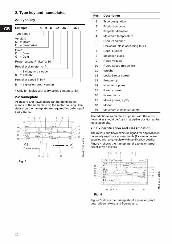
2. Type key and nameplates
2.1 Type key
* Only for liquids with a dry solids content ≤ 1.5%.
2.2 NameplateAll mixers and flowmakers can be identified by means of the nameplate on the motor housing. The details on the nameplate are required for ordering of spare parts.
Fig. 3
The additional nameplate supplied with the mixer/flowmaker should be fixed in a visible position at the installation site.
2.3 Ex certification and classificationThe mixers and flowmakers designed for application in potentially explosive environments (Ex versions) are supplied with a nameplate with certification details. Figure 4 shows the nameplate of explosion-proof direct-driven mixers.
Fig. 4
Figure 5 shows the nameplate of explosion-proof gear-driven mixers and flowmakers.
Example A M G .22 .45 .325
Type range
Version:M = MixerF = Flowmaker
Drive:D = DirectG = Gear
Power output, P2 [kW] x 10
Propeller diameter [cm]
B = Biology and sludgeB = Biology*
Propeller speed [min-1]
E = Explosion-proof versionTM
03 0
315
4804
Made in Switzerland
Type
P.c.
P1/P2
Cos.
Model
mm
A
ø
Hz
IN
°c
Pol
Tmax
Prod.No:
No:
IP Insul.class:
U V
Istart
Weight kg
A rpm
15 12
1 2 3 4 5 6 7
9
1018
17
16
19
11
14 13
8
kW
m
Pos. Description
1 Type designation
2 Production code
3 Propeller diameter
4 Maximum temperature
5 Product number
6 Enclosure class according to IEC
7 Serial number
8 Insulation class
9 Rated voltage
10 Rated speed (propeller)
11 Weight
12 Locked-rotor current
13 Frequency
14 Number of poles
15 Rated current
16 Power factor
17 Motor power, P1/P2
18 Model
19 Maximum installation depth
TM03
171
9 28
05SEV 05 ATEX 0109 X
Type
P.c.
Model
P1/P2
Cos. f
EEx
1258 II 2G
kW I
PolT
ø
CH-6105 Schachen
96257013
Prod. No.
mm No.IP°C
Hz
Insul. class:
A IStart
Weight
A nN
V
rpm
kg
NAT130°C
1 2 3 4 5 6 7
8
9
10
11
121314151617
22
21
20
19
18
10
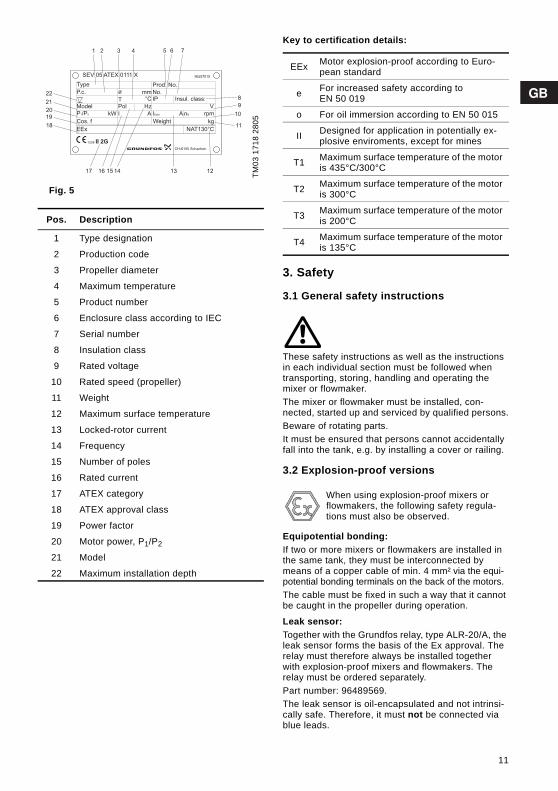
Fig. 5
Key to certification details:
3. Safety
3.1 General safety instructions
These safety instructions as well as the instructions in each individual section must be followed when transporting, storing, handling and operating the mixer or flowmaker.The mixer or flowmaker must be installed, con-nected, started up and serviced by qualified persons.Beware of rotating parts.It must be ensured that persons cannot accidentally fall into the tank, e.g. by installing a cover or railing.
3.2 Explosion-proof versions
Equipotential bonding:If two or more mixers or flowmakers are installed in the same tank, they must be interconnected by means of a copper cable of min. 4 mm² via the equi-potential bonding terminals on the back of the motors. The cable must be fixed in such a way that it cannot be caught in the propeller during operation.
Leak sensor:Together with the Grundfos relay, type ALR-20/A, the leak sensor forms the basis of the Ex approval. The relay must therefore always be installed together with explosion-proof mixers and flowmakers. The relay must be ordered separately.Part number: 96489569.The leak sensor is oil-encapsulated and not intrinsi-cally safe. Therefore, it must not be connected via blue leads.
TM03
171
8 28
05
Pos. Description
1 Type designation
2 Production code
3 Propeller diameter
4 Maximum temperature
5 Product number
6 Enclosure class according to IEC
7 Serial number
8 Insulation class
9 Rated voltage
10 Rated speed (propeller)
11 Weight
12 Maximum surface temperature
13 Locked-rotor current
14 Frequency
15 Number of poles
16 Rated current
17 ATEX category
18 ATEX approval class
19 Power factor
20 Motor power, P1/P2
21 Model
22 Maximum installation depth
SEV 05 ATEX 0111 X
Type
P.c.
Model
P1/P2
Cos. f
EEx
1258 II 2G
kW I
PolT
ø
CH-6105 Schachen
96257015
Prod. No.
mm No.IP°C
Hz
Insul. class:
A IStart
Weight
A nN
V
rpm
kg
NAT130°C
1 2 3 4 5 6 7
8
9
10
11
121314151617
22
21
20
19
18
EEx Motor explosion-proof according to Euro-pean standard
e For increased safety according to EN 50 019
o For oil immersion according to EN 50 015
II Designed for application in potentially ex-plosive enviroments, except for mines
T1 Maximum surface temperature of the motor is 435°C/300°C
T2 Maximum surface temperature of the motor is 300°C
T3 Maximum surface temperature of the motor is 200°C
T4 Maximum surface temperature of the motor is 135°C
When using explosion-proof mixers or flowmakers, the following safety regula-tions must also be observed.
11
Temperature monitoring:The motor temperature must always be monitored via the built-in PTC sensors.
Supply cable: The factory-fitted supply cable must not be short-ened.
Soft starter and frequency converter:Soft starters and frequency converters must not be used. The motor must only be operated on mains supply.
Accessories:The mixer or flowmaker must only be used together with accessories supplied and approved by Grund-fos.
Maintenance, service and repair:The mixer or flowmaker must only be dismantled by Grundfos or an authorized service workshop. This also applies to the cable entry.It is only allowed to use components produced by Grundfos for repair purposes.
Service logSpare parts etc. must be registered in a service log in order to have a 100 percent tracebility during the product life.
4. Transportation and storage
4.1 TransportationThe individual components of the mixer or flowmaker must be packed carefully to prevent any damage to the surface protection during transportation.
4.2 StorageMixers or flowmakers must be stored in a dry loca-tion in which the temperature is not subject to major fluctuations.If the mixer or flowmaker has to be stored for more than one year, the gearbox oil must be changed. The oil must be changed even if the unit has never been in use. This is necessary because of natural aging of mineral oil lubricants.
5. InstallationDuring installation, the mixer or flowmaker must only be lifted when using the suspension point.The lifting equipment supplied with the unit as well as the chain or wire used for lifting and lowering the mixer or flowmaker into the tank must not be used as universal lifting equipment.Note: Never hang the mixer or flowmaker by the supply cable. See section 11. Technical data for details about weight.
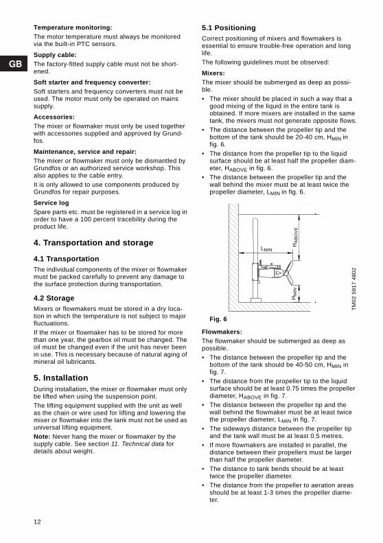
5.1 Positioning Correct positioning of mixers and flowmakers is essential to ensure trouble-free operation and long life.The following guidelines must be observed:
Mixers:The mixer should be submerged as deep as possi-ble.• The mixer should be placed in such a way that a
good mixing of the liquid in the entire tank is obtained. If more mixers are installed in the same tank, the mixers must not generate opposite flows.
• The distance between the propeller tip and the bottom of the tank should be 20-40 cm, HMIN in fig. 6.
• The distance from the propeller tip to the liquid surface should be at least half the propeller diam-eter, HABOVE in fig. 6.
• The distance between the propeller tip and the wall behind the mixer must be at least twice the propeller diameter, LMIN in fig. 6.
Fig. 6
Flowmakers:The flowmaker should be submerged as deep as possible.• The distance between the propeller tip and the
bottom of the tank should be 40-50 cm, HMIN in fig. 7.
• The distance from the propeller tip to the liquid surface should be at least 0.75 times the propeller diameter, HABOVE in fig. 7.
• The distance between the propeller tip and the wall behind the flowmaker must be at least twice the propeller diameter, LMIN in fig. 7.
• The sideways distance between the propeller tip and the tank wall must be at least 0.5 metres.
• If more flowmakers are installed in parallel, the distance between their propellers must be larger than half the propeller diameter.
• The distance to tank bends should be at least twice the propeller diameter.
• The distance from the propeller to aeration areas should be at least 1-3 times the propeller diame-ter.
TM02
591
7 48
02
HM
INH
AB
OV
E
LMIN
HA
BO
VE
LMIN
HM
IN
12

Fig. 7
• In round tanks, the flowmaker should be placed 30% of the tank radius, RTANK, from the wall and it should be turned 25° from the radius, RFLOW-MAKER, towards the centre, see fig. 8.
Fig. 8
TM02
541
7 48
02TM
02 5
422
3202
HM
IN
HA
BOV
E
LMINH
MIN
LMIN
HA
BO
VE
25˚
RTANK
RFLOWMAKERRFLOWMAKER
RTANK
13
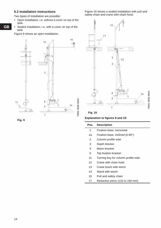
5.2 Installation instructionsTwo types of installation are possible:• Open installation, i.e. without a cover on top of the
tank.• Sealed installation, i.e. with a cover on top of the
tank.Figure 9 shows an open installation.
Fig. 9
Figure 10 shows a sealed installation with pull and safety chain and crane with chain hoist.
Fig. 10
Explanation to figures 9 and 10:
TM02
493
6 06
03
1
4
3
2
13
5
14
1a17
TM02
493
5 06
03
Pos. Description
1 Fixation base, horizontal
1a Fixation base, inclined (0-90°)
2 Column profile tube
3 Depth blocker
4 Motor bracket
5 Top fixation bracket
11 Turning key for column profile tube
12 Crane with chain hoist
13 Crane boom with winch
14 Stand with winch
15 Pull and safety chain
17 Reduction piece (120 to 100 mm)
1
4
3
12
515
2
11
1a
14

5.2.1 TorquesAll nuts and screws used for the installation must be in AISI 316L. All stainless steel threads must be greased in advance, e.g. by an ALU-paste. All stainless steel nuts and screws should be tight-ened to the following torques:
5.2.2 AMD and AMG mixersSee fig. 9 or 10 and section 5.2.1 Torques.Proceed as follows:1. Drill the holes for the mounting screws for the
top fixation bracket in the concrete.2. Fit the top fixation bracket. Insert the screws,
but leave loose.3. Place the fixation base in the right position using
a plummet.4. Drill the holes for the mounting screws for the
fixation base.5. Fit the fixation base. Insert the screws, but leave
loose.6. Position and align the column profile tube.
Shorten it to the correct length: In the case of an open installation with a railing and a crane boom with winch, cut the column profile tube approx. 600 mm above the railing.In the case of an open installation with a railing and a stand with winch, cut the column profile tube approx. 300 mm above the railing. In the case of a sealed installation, cut the col-umn profile tube so that the collar of the epoxy insulator does not touch the top fixation bracket. Adapt the outside of the square epoxy insulator to the inside of the column profile tube. The epoxy insulator must fit tightly inside the column profile tube.
7. Fasten the depth blocker in the right position.8. Tighten the screws for the top fixation bracket.9. Align the column profile tube and tighten the
screws for the fixation base.10. Position the turntable for the column profile
tube.It must be ensured that the mixer cannot be turned so much that the propeller touches the tank wall.
11. Position the crane over the column profile tube (open installation) or in the top fixation bracket (sealed installation).
12. Lift the complete mixer (motor bracket with motor) with the crane, slide it over the column profile tube and tighten the fixing screws. Check that the fixing screws and spacing pipes are fit-ted correctly and tightened, see fig. 11.
Fig. 11
Lifting equipment is absolutely essential for fitting the motor bracket onto the column profile tube. The weight of the individual unit can be found in the table on page 449.13. Slowly lower the mixer into the tank using the
crane and the pull and safety wire. Fit all the cable clamps and wire clamps one after the other. Attach the cable to the wire or chain at one-metre intervals. Attach the upper snap hook to the top fixation bracket.
Attach the supply cable to the wire or chain 800 mm above the mixer so that the cable cannot fall down and be caught in the propeller during operation.• On the drum of the winch at least three turns of
wire must remain, otherwise the wire may break loose from the drum fixation.
• The supply cable must under no circumstances be under tension. This also applies when the mixer is swung out.
• As a principle, the supply cable should be laid out in a large circle during installation to avoid sharp bends (breaking) of the cable.
• The pull and safety wire should be used as a relief for the supply cable. For this reason, it must always be pre-tensioned to approx. 250 N (~25 kg).
Fig. 12
Screws F-Class 70
Screws F-Class 80
M6 8.8 Nm 11.8 NmM8 21.4 Nm 28.7 Nm
M10 44 Nm 58 NmM12 74 Nm 100 NmM16 183 Nm 245 NmM20 370 Nm 494 Nm
TM02
553
0 35
02TM
02 4
938
1802
Sealed installation
Spacing pipes
Open installation
Supplycable
Wire clamp
Pull and safety wire
Snap hook
Cableclamp
15
14. When the motor bracket rests on the depth blocker, the distance between the propeller and the wall and the bottom of the tank must be checked. The mixer must under no circum-stances touch other installations, bottom or wall. This also applies when the mixer is swung out.
15. In the case of a sealed installation, position the mixer by fixing the turntable or tightening the screws of the clamp. For this installation type, 1.5 metres extra chain must be available for lift-ing the mixer.
5.2.3 AFG flowmakersSee fig. 9 or 10 and section 5.2.1 Torques.Proceed as follows:1. Drill the holes for the mounting screws for the
top fixation bracket in the concrete.2. Fit the top fixation bracket. Insert the screws,
but leave loose.3. Place the bottom plate in the right position using
a plummet.4. Drill the holes for the mounting screws for the
bottom plate in the bottom of the tank and insert the screws.
5. Shorten the column profile tube to the correct length so that the collar of the epoxy insulator does not touch the top fixation bracket. Adapt the outside of the square epoxy insulator to the inside of the column profile tube. The epoxy insulator must fit tightly inside the column profile tube.
6. Place the depth blocker in the right position and weld it on the column profile tube in a workshop.
7. Install the column profile tube.8. Tighten the screws for the top fixation bracket
and the bottom plate.9. Fit the top fixation bracket to the column profile
tube by means of the clamps. 10. Fit the relief wire for the supply cable to the
motor bracket.11. Position the crane in the top fixation bracket.12. Lift the complete flowmaker (motor bracket with
motor), slide it over the column profile tube and check that the fixing screws have been tight-ened.
Lifting equipment is absolutely essential for fitting the motor bracket onto the column profile tube. The weight of the individual unit can be found in the table on page 449.13. Slowly lower the flowmaker into the tank using
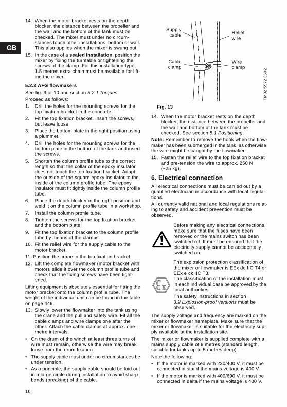
the crane and the pull and safety wire. Fit all the cable clamps and wire clamps one after the other. Attach the cable clamps at approx. one-metre intervals.
• On the drum of the winch at least three turns of wire must remain, otherwise the wire may break loose from the drum fixation.
• The supply cable must under no circumstances be under tension.
• As a principle, the supply cable should be laid out in a large circle during installation to avoid sharp bends (breaking) of the cable.
Fig. 13
14. When the motor bracket rests on the depth blocker, the distance between the propeller and the wall and bottom of the tank must be checked. See section 5.1 Positioning.
Note: Remember to remove the hook when the flow-maker has been submerged in the tank, as otherwise the wire might be caught by the flowmaker.15. Fasten the relief wire to the top fixation bracket
and pre-tension the wire to approx. 250 N (~25 kg).
6. Electrical connectionAll electrical connections must be carried out by a qualified electrician in accordance with local regula-tions.All currently valid national and local regulations relat-ing to safety and accident prevention must be observed.
The supply voltage and frequency are marked on the mixer or flowmaker nameplate. Make sure that the mixer or flowmaker is suitable for the electricity sup-ply available at the installation site. The mixer or flowmaker is supplied complete with a mains supply cable of 8 metres (standard length, suitable for tanks up to 5 metres deep).Note the following: • If the motor is marked with 230/400 V, it must be
connected in star if the mains voltage is 400 V.• If the motor is marked with 400/690 V, it must be
connected in delta if the mains voltage is 400 V.
TM02
557
2 35
02
Before making any electrical connections, make sure that the fuses have been removed or the mains switch has been switched off. It must be ensured that the electricity supply cannot be accidentally switched on.
The explosion protection classification of the mixer or flowmaker is EEx de IIC T4 or EEx e ck IIC T3.The classification of the installation must in each individual case be approved by the local authorities.The safety instructions in section 3.2 Explosion-proof versions must be observed.
Supplycable
Cableclamp
Relief wire
Wire clamp
16

Three-phase motors
Fig. 14
6.1 Motor protectionThe mixers and flowmakers are provided with the fol-lowing type of motor protection:Standard mixers incorporate three bimetallic PTO thermal switches (PTO = Protection Thermique á Ouverture), see fig. 18.Explosion-proof mixers and all flowmakers incor-porate three PTC sensors (temperature sensors) according to DIN 44 081, see fig. 19.
Function of thermal switches:The motor is protected against overheating by three thermal switches connected in series, one switch in each winding. When the maximum winding temperature is reached, the switch will open the circuit and stop the motor.When the windings have cooled to normal tempera-ture, the switch will close the circuit and the motor can be restarted. Manual restarting is necessary.See wiring diagram in fig. 18, section 6.5 Wiring dia-grams.F6: Thermal switches:• 2 leads (terminals 11 and 12).• Maximum operating voltage of switch: 250 V.• Maximum switching current: 2.5 A at cos ϕ = 1.• Cutting-out temperature: 130°C.
Function of PTC sensors:When overheated, the motor will stop. Automatic restarting is not permitted in such cases. This requires a thermistor trigger unit with a reconnection suppressor in the control circuit of the motor contac-tor.See wiring diagram in fig. 19, section 6.5 Wiring dia-grams.ϑ1, ϑ2, ϑ3: PTC sensors: • 2 leads (terminals 31 and 32). • Maximum voltage at the terminals: Umax. = 2.5 V
(AC/DC). • Resistance between terminals 31 and 32:
- at room temperature R = 300 to 750 Ω.- at cutting-out temperature R ≥ 4000 Ω.
Note: For transmission tests at terminals 31 and 32, the test voltage must not exceed 2.5 V (AC/DC). Use an ohmmeter for the test.
6.2 Gearbox/shaft seal housing protectionThe gearbox/shaft seal housing is monitored for the ingress of water by a leak sensor incorporated in the gearbox/shaft seal housing.If the monitoring function is required, the leak sensor must be connected to a Grundfos relay, type ALR-20/A. The ALR-20/A relay must be ordered sep-arately. Part number: 96489569.
Note: The cable between the relay and the mixer/flowmaker must be maximum 50 metres. An external alarm indicator, if any, must be connected to the potential-free output, terminals 1 and 3 or 4, respec-tively. Maximum load: 48 V, 1 A.When the ALR-20/A relay is connected, a current of up to 10 mA will flow through the leak sensor (termi-nals 21 and 22) in case water penetrates into the oil chamber. The relay triggers an alarm signal and/or switches off the motor.See wiring diagram in fig. 18 or 19, section 6.5 Wiring diagrams.B: Leak sensor:• 2 leads (terminals 21 and 22).• Maximum operating voltage: Approx. 8.6 V.• Maximum current: 1 to 10 mA.To adjust the sensitivity of the ALR-20/A relay, pro-ceed as follows:1. Turn the adjusting screw on the relay (pos. a)
until the indicator light (pos. b) illuminates.2. Turn the adjusting screw in the opposite direction
until the indicator light goes out.3. Continue to turn the adjusting screw 60° (same
direction as under point 2).
Fig. 15
TM02
495
3 20
02
Explosion-proof mixers must be protected against too high temperature by means of PTC sensors. The sensors must be con-nected to a certified signal converter.
W2
U1
U2
V1
V2
W1
L1 L2 L3
W2
U1
U2
V1
V2
W1
L1 L2 L3
Delta Star
Explosion-proof pumps must be connected to a Grundfos relay, type ALR-20/A Ex. Classification: EEx ib IIC.110 V: Part no. 96257430.230 V: Part no. 96257400.
TM02
886
6 09
04
ALR 20/A
5 7
Netz 230V 40-60Hz P3VARel. Ue 400V le 2.5A AC15
2 10 4 1 3A1 A2
NetzRel.
a
b
17

Fig. 16
Fig. 17
Note: Do not check the leak sensor with an ohmme-ter or other measuring instruments. The leak sensor is an electronic component.
6.3 Overload relaysThe motor must be protected against overload via a thermal delay relay according to local regulations. The relay must be adjusted to the rated current stated on the nameplate.In the case of star-delta starting, the adjustable value is to be IN x 0.58. In all six mains leads (U1, V1, W1 and U2, V2, W2), electro-thermal all-pole triggers are to be incorpo-rated.
6.4 Starting method
6.4.1 MixersContinuous operation:Direct starting can be used for motors of 1.5 to 3.0 kW.Star-delta starting is recommended for motors of 4.0 kW and up.
Intermittent operation:Star-delta starting is mandatory throughout the entire power range.
6.4.2 FlowmakersFlowmakers must be started via a softstarter.
TM03
206
0 35
05TM
02 4
954
2002
2 10 4 1 3
A1 A2
arnold ag
Lecksonden RelaisNetz 230V 50-60Hz P3VA
II (2)G [EEx ib] IIC nur für den Anschluss von Arnold AG
Lecksonden Typ AL05 Ex
Schaltpunkt Storung
ALR 20/A Ex
SEV 05 ATEX 0131
12585 7
Sonde
Rel.Netz
CH - 6105 Schachen
A Grundfos Company
Leak sensor ALR-20/A
18

6.5 Wiring diagramsThree thermal switches (PTO)
Fig. 18
Three PTC sensors
Fig. 19
TM02
494
0 18
02
Terminals Description
1, 2, 3, 4, 5, 6
Ends of the three stator windings (U1, U2, V1, V2, W1, W2)
11, 12 Thermal switches (F6)
21, 22 Leak sensor in gearbox (B)
B
TM02
493
2 20
02
Terminals Description
1, 2, 3, 4, 5, 6
Ends of the three stator windings (U1, U2, V1, V2, W1, W2)
31, 32 PTC sensors (according to DIN 44 081) (ϑ1, ϑ2, ϑ3)
21, 22 Leak sensor in gearbox (B)
19

6.6 Block diagram
Fig. 20
6.7 Direction of rotationWhen the electrical connections have been carried out, it must be ensured that the mixer or flowmaker propeller is rotating in the correct direction (when viewed from the motor, the propeller should rotate clockwise). An arrow on the motor housing shows the correct direction of rotation.If the mixer or flowmaker propeller rotates in the wrong direction, interchange two phases of the mains supply (L1, L2, L3).
6.8 Protection from electro-chemical corrosion
Two different metals or alloys cause electro-chemical corrosion if they are connected by an electrolyte. This applies if more than one mixer or flowmaker are installed in the same tank. The following additional protection is therefore recommended:• galvanic separation of the earth lead from the neu-
tral lead or• galvanic separation of the mains supply by means
of isolation transformer.
The earth lead must be separated in such a way as to ensure that no direct current can flow through it. It must still function as a protective lead. This can be achieved with a limiting unit (polarization cell or anti-parallel diode) or an isolation transformer.
Fig. 21
7. Frequency converter operation (AMD.xx.45.xxx.E)
Mixer types AMD.15.45B.710.E; AMD.35.45B.705.E; AMD.20.45.700.E and AMD.30.45.710.E can be con-trolled by frequency converters, provided the follow-ing conditions are observed:1. The motors are equipped with direct temperature
monitoring via PTC for protection against too high motor temperature in case of operating dis-turbances.The PTC sensors in the windings must be connected to a suitable relay. The relay must be incorporated in the mixer controller.
2. The motors may be connected to frequency con-verters with the settings and rated data stated in the following table.
3. Set the frequency converter according to the rated motor data, especially the values of cur-rent, voltage, frequency and power. See the nameplate of the motor.
4. The relation between voltage and frequency is selected lineary in the duty range from 30 to 50 Hz. At frequencies below the minimum oper-ating frequency (start-up), the voltage may devi-
TM02
494
1 20
02
Pos. Description
1 Sensor, e.g. level sensor
2 Star or star-delta starting device
3 PTO thermal switches or PTC sensors
4 Contact for alarm signal and/or switching off the motor
5 Leak sensor in gearbox, see 6.2 Gearbox/shaft seal housing protection
PE
, U, V
, W
11 ,
12
21 ,
22
1 2
3 5
4
PE
, U, V
, W
11, 1
2
21, 2
2
TM02
494
3 06
03
Pos. Description
1 Limiting unit
2 Earth lead
3 Isolation transformer
When using an isolation transformer, the ratio between starting current and rated current (IA/IN) must not be altered.
L1L2L3NPE
1
3
2
2
20
ate from the lineary relation, it may, however, not exceed value at the minimum operating fre-quency. At frequencies over 50 Hz, the voltage is constantly 400 V.
5. There must be no slip compensation.
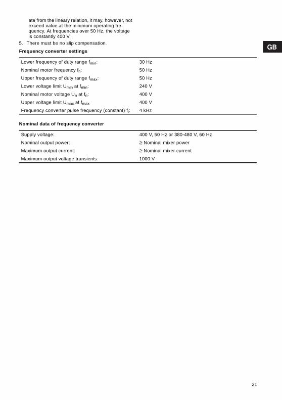
Frequency converter settings
Nominal data of frequency converter
Lower frequency of duty range fmin: 30 Hz
Nominal motor frequency fn: 50 Hz
Upper frequency of duty range fmax: 50 Hz
Lower voltage limit Umin at fmin: 240 V
Nominal motor voltage Un at fn: 400 V
Upper voltage limit Umax at fmax 400 V
Frequency converter pulse frequency (constant) ft: 4 kHz
Supply voltage: 400 V, 50 Hz or 380-480 V, 60 Hz
Nominal output power: ≥ Nominal mixer power
Maximum output current: ≥ Nominal mixer current
Maximum output voltage transients: 1000 V
21

8. Start-upBefore starting up the mixer or flowmaker, the oil level in the gearbox/shaft seal housing must be checked. Remove the oil level screw (pos. 3, fig. 22) and check the oil level.
If required, fill oil into the gearbox/shaft seal housing through the oil filling hole (pos. 2). For oil quality and quantity, see section 9.4 Oil.It is necessary to remove the impeller of AMD to check the oil level.If the mixer or flowmaker has been in stock for a period before start-up, see section 9.3 Service chart.
Fig. 22
Before start-up, • check that the propeller is rotating in the correct
direction, see section 6.7 Direction of rotation.• make sure that the mixer or flowmaker is com-
pletely submerged in the liquid to be mixed.Note: The mixer or flowmaker must always be submerged during operation.
• make sure that there are no solid objects in the tank.
• make sure that no persons can fall into the tank.
9. Service
Before starting any work on mixers or flowmakers used to handle liquids which could constitute a haz-ard to health, thorough cleaning/venting of mixer or flowmaker, tank, etc. must be carried out according to local regulations.
9.1 Explosion-proof mixers and flowmakers
Explosion-proof mixers or flowmakers must be serv-iced and repaired by Grundfos or by a service part-ner appointed by Grundfos.
9.1.1 Spare partsDamaged mixer/flowmaker parts should always be replaced by new approved parts. Motor parts must not be reconditioned by machining, retapping, weld-ing, etc.
9.2 Contaminated mixer or flowmakerNote: If a mixer or flowmaker has been used for a liquid which is injurious to health or toxic, the mixer will be classified as contaminated.If Grundfos is requested to service the mixer or flow-maker, Grundfos must be contacted with details about the liquid, etc. before the mixer or flowmaker is returned for service. Otherwise Grundfos can refuse to accept the mixer or flowmaker for service. Possible costs of returning the mixer or flowmaker are paid by the customer. However, any application for service (no matter to whom it may be made) must include details about the liquid if the mixer or flowmaker has been used for liquids which are injurious to health or toxic.
When slackening the oil level screw, note that pressure may have built up in the chamber. Do not remove the screw until the pressure has been fully relieved.
TM02
493
7 18
02
1 3
2
Before starting any work on mixers or flow-makers, make sure that the fuses have been removed or the mains switch has been switched off. It must be ensured that the electricity supply cannot be acciden-tally switched on.All rotating parts must have stopped mov-ing.
All regulations applying to mixers or flow-makers installed in potentially explosive environments must be observed.It must be ensured that no work is carried out in potentially explosive atmosphere.
22

9.3 Service chart
* Does not apply to AMD.xx.45.
Type Service instructions Lubrication Inspection
Electric motor All
Keep the motor housing clean (otherwise cooling is affected). The motor hous-ing may only be disman-tled by Grundfos.
The roller bearings are maintenance-free. They should be replaced if they get noisy.
The motors are filled with dielectric oil*. No oil level check and oil change are required.
Supply cable All
The supply cable must be checked twice a year for surface damage, strain, kinks, etc. If damaged, the cable must be replaced by Grundfos.
Shaft seal housing AMD
Change the oil every 8,000 operating hours. Minimum every two years.
Gearbox Allexcept AMD
Check the gearbox for leaks twice a year.
Change the oil after 500 operating hours.Then every 8,000 operat-ing hours or after one year of operation.
Check the oil level twice a year, see section 9.4.3 Oil quantity. If refilling is re-quired, see section 9.4.1 Gearbox and shaft seal housing – oil quality.
Propeller All
Check the propeller blades regularly for wear and tear. Remove any material wound around the blades, such as ropes, threads, etc. which may cause une-ven running and oscillation of the installation. In case of strong turbulence, cleaning is absolutely nec-essary.
Winch All
Spray the winch with a protective coating of oil at regular intervals (to pre-vent corrosion).
The gear teeth and the bearing bushes must be lubricated twice a year with an all-purpose grease.
Pull and safety wire
AllRegular oiling or greasing increases the life of the wire.
Check the wire regularly and always before using the winch. Replace the wire, if required.
Screws All
Always check that all screws in the motor bracket are properly tight-ened.Check the screws in the fixation base/bottom plate every time the tank is empty.
23

9.4 Oil
9.4.1 Gearbox and shaft seal housing – oil qualityGear oil, designation according to DIN 51 502.AMD: ISO VG 150.AMG, AFG: ISO VG 220.
9.4.2 Motor – oil qualityShell Fluid 4600.The motor oil should only be changed if the motor is dismantled for service or repair.
9.4.3 Oil quantityNon-explosion-proof mixers and flowmakers
Explosion-proof mixers and flowmakers
TypeGearbox/shaft seal housing
[l]
Motor[l]
AMD.18.32.9500.25 1.7
AMD.28.39.930
AMD.15.45B.710
0.3 -
AMD.25.45B.690
AMD.35.45B.705
AMD.45.45B.675
AMD.20.45.700
AMD.30.45.710
AMD.40.45.695
AMG.15.40.325
0.7
2.5AMG.22.45.325
AMG.30.47.3282.0
AMG.40.52.326
AMG.55.50.335
1.56.5
AMG.75.58.336
AMG.110.68.334 4.5
AMG.150.73.3542.5 7.0
AMG.185.78.351
AFG.15.130.76
1.0
2.5AFG.22.130.77
AFG.30.130.922.0
AFG.40.130.93
AFG.13.180.30
1.0
2.5AFG.18.180.34
AFG.24.180.392.0
AFG.37.180.46
AFG.15.230.22
1.9
2.5AFG.22.230.25
AFG.30.230.292.0
AFG.40.230.35
TypeGearbox/
shaft seal housing[l]
AMD.15.45B.710.E
0.3
AMD.25.45B.690.E
AMD.35.45B.705.E
AMD.45.45B.675.E
AMD.20.45.700.E
AMD.30.45.710.E
AMD.40.45.695.E
AMG.15.40.340.E
0.7AMG.22.45.336.E
AMG.30.47.338.E
AMG.40.52.334.E
AMG.55.50.344.E
1.5AMG.75.58.343.E
AMG.110.68.342.E
AMG.150.73.355.E2.5
AMG.185.78.356.E
AFG.15.130.79.E
1.0AFG.22.130.78.E
AFG.30.130.95.E
AFG.40.130.94.E
AFG.13.180.30.E
1.0AFG.18.180.34.E
AFG.24.180.39.E
AFG.37.180.46.E
AFG.15.230.23.E
1.9AFG.22.230.26.E
AFG.30.230.30.E
AFG.40.230.34.E
24
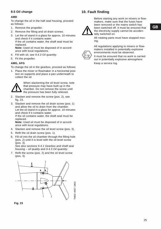
9.5 Oil changeAMDTo change the oil in the haft seal housing, proceed as follows:1. Remove the propeller.2. Remove the filling and oil drain screws.3. Let the oil stand in a glass for approx. 10 minutes
and check if it contains water. If the oil contains water, the shaft seal must be replaced.Note: Used oil must be disposed of in accord-ance with local regulations.
4. Fill with oil, see 9.4.3 Oil quantity.5. Fit the propeller.
AMG, AFGTo change the oil in the gearbox, proceed as follows:1. Place the mixer or flowmaker in a horizontal posi-
tion on supports and place a pan underneath to collect the oil.
2. Slacken and remove the screw (pos. 2), see fig. 23.
3. Slacken and remove the oil drain screw (pos. 1) and allow the oil to drain from the chamber.Let the oil stand in a glass for approx. 10 minutes and check if it contains water. If the oil contains water, the shaft seal must be replaced.Note: Used oil must be disposed of in accord-ance with local regulations.
4. Slacken and remove the oil level screw (pos. 3).5. Refit the oil drain screw (pos. 1).6. Fill oil into the oil chamber through the filling hole
(pos. 2) until it is level with the oil level screw (pos. 3).See also sections 9.4.1 Gearbox and shaft seal housing – oil quality and 9.4.3 Oil quantity.
7. Refit the screw (pos. 2) and the oil level screw (pos. 3).
Fig. 23
10. Fault finding
When slackening the oil level screw, note that pressure may have built up in the chamber. Do not remove the screw until the pressure has been fully relieved.
TM02
493
7 18
02
1 3
2
Before starting any work on mixers or flow-makers, make sure that the fuses have been removed or the mains switch has been switched off. It must be ensured that the electricity supply cannot be acciden-tally switched on.All rotating parts must have stopped mov-ing.
All regulations applying to mixers or flow-makers installed in potentially explosive environments must be observed.It must be ensured that no work is carried out in potentially explosive atmosphere.Keep a service log.
25
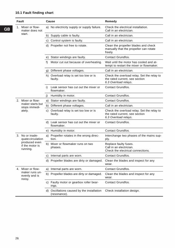
10.1 Fault finding chart
Fault Cause Remedy
1. Mixer or flow-maker does not start.
a) No electricity supply or supply failure. Check the electrical installation.Call in an electrician.
b) Supply cable is faulty. Call in an electrician.
c) Control system is faulty. Call in an electrician.
d) Propeller not free to rotate. Clean the propeller blades and check manually that the propeller can rotate freely.
e) Stator windings are faulty. Contact Grundfos.
f) Motor cut out because of overheating. Wait until the motor has cooled and at-tempt to restart the mixer or flowmaker.
g) Different phase voltages. Call in an electrician.
h) Overload relay is set too low or is faulty.
Check the overload relay. Set the relay to the rated current, see section 6.3 Overload relays.
i) Leak sensor has cut out the mixer or flowmaker.
Contact Grundfos.
j) Humidity in motor. Contact Grundfos.
2. Mixer or flow-maker starts but stops immedi-ately.
a) Stator windings are faulty. Contact Grundfos.
b) Different phase voltages. Call in an electrician.
c) Overload relay is set too low or is faulty.
Check the overload relay. Set the relay to the rated current, see section 6.3 Overload relays.
d) Leak sensor has cut out the mixer or flowmaker.
Contact Grundfos.
e) Humidity in motor. Contact Grundfos.
3. No or inade-quate circulation produced even if the motor is running.
a) Propeller rotates in the wrong direc-tion.
Interchange two phases of the mains sup-ply.
b) Mixer or flowmaker runs on two phases.
Replace faulty fuses.Call in an electrician.Check the electrical connections.
c) Internal parts are worn. Contact Grundfos.
d) Propeller blades are dirty or damaged. Clean the blades and inspect for any wear.
4. Mixer or flow-maker runs un-evenly and is noisy.
a) Internal parts are worn. Contact Grundfos.
b) Propeller blades are dirty or damaged. Clean the blades and inspect for any wear.
c) Faulty motor or gearbox roller bear-ings.
Contact Grundfos.
d) Oscillations caused by the installation (resonance).
Check installation design.
26

5. High current and power con-sumption.
a) Wrong voltage supply or supply fail-ure.
Check the electrical installation.Call in an electrician.
b) Supply cable is faulty. Call in an electrician.
c) Control system is faulty. Call in an electrician.
d) Propeller not free to rotate. Clean the propeller blades and check manually that the propeller can rotate freely.
e) Stator windings are faulty. Contact Grundfos.
f) Mixer or flowmaker runs on two phases.
Replace faulty fuses.Call in an electrician.Check the electrical connections.
g) Internal parts are worn. Contact Grundfos.
h) Faulty motor or gearbox roller bear-ings.
Contact Grundfos.
Fault Cause Remedy
27
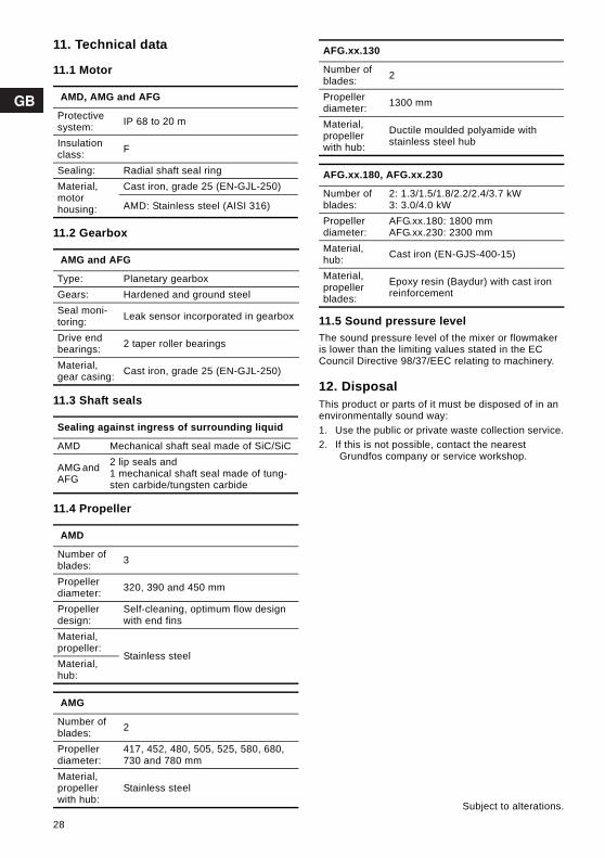
11. Technical data
11.1 Motor
11.2 Gearbox
11.3 Shaft seals
11.4 Propeller
11.5 Sound pressure levelThe sound pressure level of the mixer or flowmaker is lower than the limiting values stated in the EC Council Directive 98/37/EEC relating to machinery.
12. DisposalThis product or parts of it must be disposed of in an environmentally sound way:1. Use the public or private waste collection service.2. If this is not possible, contact the nearest
Grundfos company or service workshop.
AMD, AMG and AFG
Protective system: IP 68 to 20 m
Insulation class: F
Sealing: Radial shaft seal ringMaterial, motorhousing:
Cast iron, grade 25 (EN-GJL-250)
AMD: Stainless steel (AISI 316)
AMG and AFG
Type: Planetary gearboxGears: Hardened and ground steelSeal moni-toring: Leak sensor incorporated in gearbox
Drive end bearings: 2 taper roller bearings
Material, gear casing: Cast iron, grade 25 (EN-GJL-250)
Sealing against ingress of surrounding liquid
AMD Mechanical shaft seal made of SiC/SiC
AMG and AFG
2 lip seals and 1 mechanical shaft seal made of tung-sten carbide/tungsten carbide
AMD
Number of blades: 3
Propeller diameter: 320, 390 and 450 mm
Propeller design:
Self-cleaning, optimum flow design with end fins
Material, propeller:
Stainless steelMaterial, hub:
AMG
Number of blades: 2
Propeller diameter:
417, 452, 480, 505, 525, 580, 680, 730 and 780 mm
Material, propeller with hub:
Stainless steel
AFG.xx.130
Number of blades: 2
Propeller diameter: 1300 mm
Material, propeller with hub:
Ductile moulded polyamide with stainless steel hub
AFG.xx.180, AFG.xx.230
Number of blades:
2: 1.3/1.5/1.8/2.2/2.4/3.7 kW3: 3.0/4.0 kW
Propeller diameter:
AFG.xx.180: 1800 mmAFG.xx.230: 2300 mm
Material, hub: Cast iron (EN-GJS-400-15)
Material, propeller blades:
Epoxy resin (Baydur) with cast iron reinforcement
Subject to alterations.
28

DimensionsAMD
TM03
028
3 47
04
C
D
E
B
A
TypeNominel
rating [kW]
A[mm]
B[mm]
C[mm]
D[mm]
E[mm]
Weight incl.
bracket [kg]
AMD.18.32.950 1.8587 210 315 300
320 62
AMD.28.39.930 2.8 390 63
AMD.15.45B.710 1.5456
210
175
210 450
50AMD.25.45B.690 2.5
AMD.35.45B.705 3.5491 193 59
AMD.45.45B.675 4.5
AMD.20.45.700 2.0 456 175 50
AMD.30.45.710 3.0491 193 59
AMD.40.45.695 4.0
449

AMG, AFG
TM02
494
4 22
02
A
B C
D
E
TypeNominal
rating [kW]
A[mm]
B[mm]
C[mm]
D[mm]
E[mm]
Weight incl. bracket
[kg]
AMG.15.40.325 1.5 720
200 305 400
417 78
AMG.22.45.325 2.2 735 452 78
AMG.30.47.328 3.0 750 480 85
AMG.40.52.326 4.0 760 525 85
AMG.55.50.335 5.5 980
270
455
500
505 166
AMG.75.58.336 7.5 990 580 168
AMG.110.68.334 11.0 1010 680 177
AMG.150.73.354 15.0 1160315 630
730 275
AMG.185.78.351 18.5 1180 780 280
AFG.15.130.76 1.5
795 200 353 500 1300
100
AFG.22.130.77 2.2 100
AFG.30.130.92 3.0 105
AFG.40.130.93 4.0 105
AFG.13.180.30 1.3
1100 302 540 450 1800
190AFG.18.180.34 1.8
AFG.24.180.39 2.4198
AFG.37.180.46 3.7
AFG.15.230.22 1.5
1100 302 540 450 2300
200
AFG.22.230.25 2.2 200
AFG.30.230.29 3.0 233
AFG.40.230.35 4.0 233
450

InstallationSealed installation, AMD.xx.45 with chain hoist
TM0
3 48
01
280
6
451

Standard installation, AMD.xx.45 with winch
TM0
3 48
02
280
6
452

Standard installation, AMD.xx.45
TM0
3 48
03
280
6
453
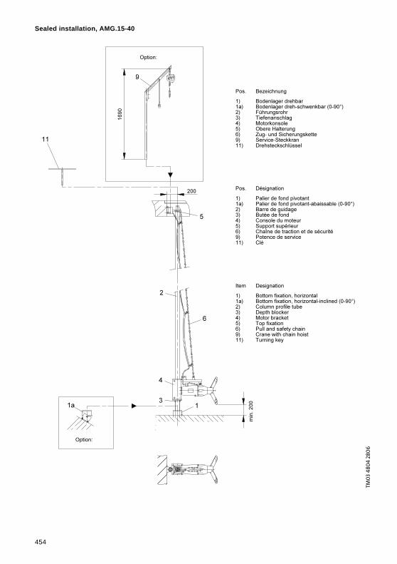
Sealed installation, AMG.15-40
TM0
3 48
04
280
6
454

Standard installation, AMG.15-40
TM0
3 48
05
280
6
455
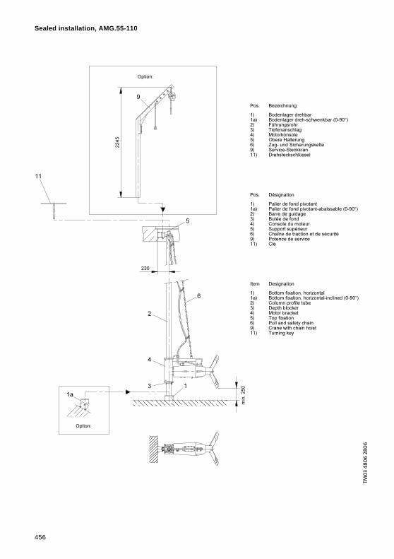
Sealed installation, AMG.55-110
TM0
3 48
06
280
6
456
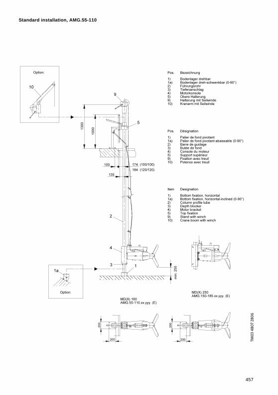
Standard installation, AMG.55-110
TM0
3 48
07
280
6
457
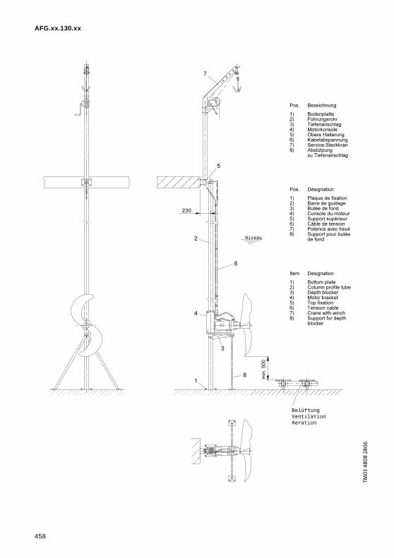
AFG.xx.130.xx
TM0
3 48
08
280
6
458

AFG.xx.180.xx
TM0
3 48
10 2
806
459
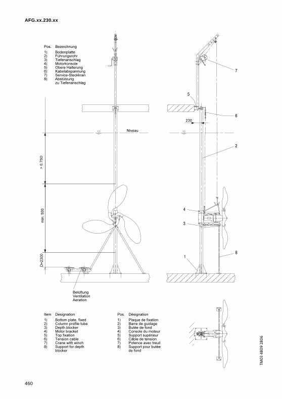
AFG.xx.230.xx
TM0
3 48
09
280
6
460

461

462
DenmarkGRUNDFOS DK A/S Martin Bachs Vej 3 DK-8850 Bjerringbro Tlf.: +45-87 50 50 50 Telefax: +45-87 50 51 51 E-mail: [email protected]/DK
ArgentinaBombas GRUNDFOS de Argentina S.A.Ruta Panamericana km. 37.500 Lote 34A1619 - GarinPcia. de Buenos AiresPhone: +54-3327 414 444Telefax: +54-3327 411 111
AustraliaGRUNDFOS Pumps Pty. Ltd. P.O. Box 2040 Regency Park South Australia 5942 Phone: +61-8-8461-4611 Telefax: +61-8-8340 0155
AustriaGRUNDFOS Pumpen Vertrieb Ges.m.b.H.Grundfosstraße 2 A-5082 Grödig/Salzburg Tel.: +43-6246-883-0 Telefax: +43-6246-883-30
BelgiumN.V. GRUNDFOS Bellux S.A. Boomsesteenweg 81-83 B-2630 Aartselaar Tél.: +32-3-870 7300 Télécopie: +32-3-870 7301
BelorussiaПредставительство ГРУНДФОС в Минске220090 Минск ул.Олешева 14 Телефон: (8632) 62-40-49Факс: (8632) 62-40-49
Bosnia/HerzegovinaGRUNDFOS SarajevoParomlinska br. 16,BiH-71000 SarajevoPhone: +387 33 713290Telefax: +387 33 231795
BrazilGRUNDFOS do Brasil Ltda.Rua Tomazina 106CEP 83325 - 040Pinhais - PRPhone: +55-41 668 3555Telefax: +55-41 668 3554
BulgariaGRUNDFOS Pumpen VertriebRepresentative Office - BulgariaBulgaria, 1421 SofiaLozenetz District105-107 Arsenalski blvd. Phone: +359 2963 3820, 2963 5653Telefax: +359 2963 1305
CanadaGRUNDFOS Canada Inc. 2941 Brighton Road Oakville, Ontario L6H 6C9 Phone: +1-905 829 9533 Telefax: +1-905 829 9512
ChinaGRUNDFOS Pumps (Shanghai) Co. Ltd.22 Floor, Xin Hua Lian Building755-775 Huai Hai Rd, (M)Shanghai 200020PRCPhone: +86-512-67 61 11 80Telefax: +86-512-67 61 81 67
CroatiaGRUNDFOS predstavništvo ZagrebCebini 37, BuzinHR-10000 ZagrebPhone: +385 1 6595 400 Telefax: +385 1 6595 499
Czech RepublicGRUNDFOS s.r.o.Čapkovského 21779 00 OlomoucPhone: +420-585-716 111Telefax: +420-585-716 299
EstoniaGRUNDFOS Pumps Eesti OÜPeterburi tee 4411415 TallinnTel: + 372 606 1690Fax: + 372 606 1691
FinlandOY GRUNDFOS Pumput AB Mestarintie 11 FIN-01730 Vantaa Phone: +358-3066 5650 Telefax: +358-3066 56550
FrancePompes GRUNDFOS Distribution S.A. Parc d’Activités de Chesnes 57, rue de Malacombe F-38290 St. Quentin Fallavier (Lyon) Tél.: +33-4 74 82 15 15 Télécopie: +33-4 74 94 10 51
GermanyGRUNDFOS GMBHSchlüterstr. 3340699 ErkrathTel.: +49-(0) 211 929 69-0 Telefax: +49-(0) 211 929 69-3799e-mail: [email protected] in Deutschland:e-mail: [email protected]
GreeceGRUNDFOS Hellas A.E.B.E. 20th km. Athinon-Markopoulou Av. P.O. Box 71 GR-19002 Peania Phone: +0030-210-66 83 400 Telefax: +0030-210-66 46 273
Hong KongGRUNDFOS Pumps (Hong Kong) Ltd. Unit 1, Ground floor Siu Wai Industrial Centre 29-33 Wing Hong Street & 68 King Lam Street, Cheung Sha Wan Kowloon Phone: +852-27861706 / 27861741 Telefax: +852-27858664
HungaryGRUNDFOS Hungária Kft.Park u. 8H-2045 Törökbálint, Phone: +36-23 511 110Telefax: +36-23 511 111
IndiaGRUNDFOS Pumps India Private Limited118 Old Mahabalipuram RoadThoraipakkamChamiers RoadChennai 600 096Phone: +91-44 2496 6800
IndonesiaPT GRUNDFOS Pompa Jl. Rawa Sumur III, Blok III / CC-1 Kawasan Industri, Pulogadung Jakarta 13930 Phone: +62-21-460 6909 Telefax: +62-21-460 6910 / 460 6901
IrelandGRUNDFOS (Ireland) Ltd. Unit A, Merrywell Business ParkBallymount Road LowerDublin 12 Phone: +353-1-4089 800 Telefax: +353-1-4089 830
ItalyGRUNDFOS Pompe Italia S.r.l. Via Gran Sasso 4I-20060 Truccazzano (Milano)Tel.: +39-02-95838112 Telefax: +39-02-95309290 / 95838461
JapanGRUNDFOS Pumps K.K.1-2-3, Shin MiyakodaHamamatsu CityShizuoka pref. 431-21Phone: +81-53-428 4760Telefax: +81-53-484 1014
KoreaGRUNDFOS Pumps Korea Ltd.6th Floor, Aju Building 679-5Yeoksam-dong, Kangnam-ku, 135-916Seoul, KoreaPhone: +82-2-5317 600Telefax: +82-2-5633 725
LatviaSIA GRUNDFOS Pumps Latvia Deglava biznesa centrsAugusta Deglava ielā 60, LV-1035, Rīga,Tālr.: + 371 714 9640, 7 149 641Fakss: + 371 914 9646
LithuaniaGRUNDFOS Pumps UABSmolensko g. 6LT-03201 VilniusTel: + 370 52 395 430Fax: + 370 52 395 431
MalaysiaGRUNDFOS Pumps Sdn. Bhd.7 Jalan Peguam U1/25Glenmarie Industrial Park40150 Shah AlamSelangor Phone: +60-3-5569 2922Telefax: +60-3-5569 2866
MéxicoBombas GRUNDFOS de México S.A. de C.V. Boulevard TLC No. 15Parque Industrial Stiva AeropuertoApodaca, N.L. 66600Phone: +52-81-8144 4000 Telefax: +52-81-8144 4010
NetherlandsGRUNDFOS Nederland B.V. Postbus 104 NL-1380 AC Weesp Tel.: +31-294-492 211 Telefax: +31-294-492244/492299
New ZealandGRUNDFOS Pumps NZ Ltd.17 Beatrice Tinsley CrescentNorth Harbour Industrial EstateAlbany, AucklandPhone: +64-9-415 3240Telefax: +64-9-415 3250
NorwayGRUNDFOS Pumper A/S Strømsveien 344 Postboks 235, Leirdal N-1011 Oslo Tlf.: +47-22 90 47 00 Telefax: +47-22 32 21 50
PolandGRUNDFOS Pompy Sp. z o.o.ul. Klonowa 23Baranowo k. PoznaniaPL-62-081 PrzeźmierowoPhone: (+48-61) 650 13 00Telefax: (+48-61) 650 13 50
PortugalBombas GRUNDFOS Portugal, S.A. Rua Calvet de Magalhães, 241Apartado 1079P-2770-153 Paço de ArcosTel.: +351-21-440 76 00Telefax: +351-21-440 76 90
RomâniaGRUNDFOS Pompe România SRLBd. Biruintei, nr 103 Pantelimon county IlfovPhone: +40 21 200 4100Telefax: +40 21 200 4101E-mail: [email protected]
RussiaООО ГрундфосРоссия, 109544 Москва, Школьная 39Тел. (+7) 095 737 30 00, 564 88 00Факс (+7) 095 737 75 36, 564 88 11E-mail [email protected]
Serbia and MontenegroGRUNDFOS Predstavništvo BeogradDr. Milutina Ivkovića 2a/29YU-11000 Beograd Phone: +381 11 26 47 877 / 11 26 47 496Telefax: +381 11 26 48 340
SingaporeGRUNDFOS (Singapore) Pte. Ltd. 24 Tuas West Road Jurong Town Singapore 638381 Phone: +65-6865 1222 Telefax: +65-6861 8402
SloveniaGRUNDFOS PUMPEN VERTRIEB Ges.m.b.H.,Podružnica LjubljanaBlatnica 1, SI-1236 TrzinPhone: +386 1 563 5338Telefax: +386 1 563 2098E-mail: [email protected]
SpainBombas GRUNDFOS España S.A. Camino de la Fuentecilla, s/n E-28110 Algete (Madrid) Tel.: +34-91-848 8800 Telefax: +34-91-628 0465
SwedenGRUNDFOS AB Lunnagårdsgatan 6 431 90 Mölndal Tel.: +46-0771-32 23 00 Telefax: +46-31 331 94 60
SwitzerlandGRUNDFOS Pumpen AG Bruggacherstrasse 10 CH-8117 Fällanden/ZH Tel.: +41-1-806 8111 Telefax: +41-1-806 8115
TaiwanGRUNDFOS Pumps (Taiwan) Ltd. 7 Floor, 219 Min-Chuan Road Taichung, Taiwan, R.O.C. Phone: +886-4-2305 0868Telefax: +886-4-2305 0878
ThailandGRUNDFOS (Thailand) Ltd. 947/168 Moo 12, Bangna-Trad Rd., K.M. 3,Bangna, PhrakanongBangkok 10260 Phone: +66-2-744 1785 ... 91Telefax: +66-2-744 1775 ... 6
TurkeyGRUNDFOS POMPA San. ve Tic. Ltd. Sti.Gebze Organize Sanayi Bölgesi Ihsan dede Caddesi,2. yol 200. Sokak No. 20441490 Gebze/ KocaeliPhone: +90 - 262-679 7979Telefax: +90 - 262-679 7905E-mail: [email protected]
UkraineТОВ ГРУНДФОС Украинаул. Владимирская, 71, оф. 45г. Киев, 01033, Украина,Тел. +380 44 289 4050Факс +380 44 289 4139
United Arab EmiratesGRUNDFOS Gulf DistributionP.O. Box 16768Jebel Ali Free ZoneDubaiPhone: +971-4- 8815 166Telefax: +971-4-8815 136
United KingdomGRUNDFOS Pumps Ltd. Grovebury Road Leighton Buzzard/Beds. LU7 8TL Phone: +44-1525-850000 Telefax: +44-1525-850011
U.S.A.GRUNDFOS Pumps Corporation 17100 West 118th TerraceOlathe, Kansas 66061Phone: +1-913-227-3400 Telefax: +1-913-227-3500
UsbekistanПредставительство ГРУНДФОС в Ташкенте700000 Ташкент ул.Усмана Носира 1-й тупик 5Телефон: (3712) 55-68-15Факс: (3712) 53-36-35
Addresses revised 10.11.2006

www.grundfos.com
Being responsible is our foundationThinking ahead makes it possible
Innovation is the essence
96498078 1206 191Repl. 96498078 0305