aluminum composite panel - pivotdecor.com acp.pdf · 4 connection design of curtain wall components...
TRANSCRIPT
Aluminum Composite Panel

ⅠIntroduction to the finished goods and production line about ACP………………1
ⅡAdvantages of ACP…………………….……………………………………………22
1 ACP, as advertising panels, compared with traditional advertising aterials …22
2 ACP, as curtain wall panels, compared with traditional curtain wall aterials …23
Ⅲ Flame-resistant panels and identification methods from common ACP ………24
Ⅳ Methods of testing Aluminum Composite Panels ……………………………...28
1 Test Method of PVDF fluorocarbon resin content……………………………..…28
2 Test method of folding life under cyclic deformation of Aluminum Composite
Panels ………………………………………………………………………….….…33
3 Test method of natural environmental exposure for Aluminum Composite
Panels ……………………………………………………………….………………35
4 Identification methods of common plastics ………………………………………39
5 Contrast table of different aluminum series ………………………………………40
6 Performance contrast table of different core materials……………………………42
ⅠManufacturing and fabrication ……………………………………………………44
1 Manufacturing method of Aluminum Composite Panels…………………………44
2 Fabrication method of Aluminum Composite Panels ……………………………48
ⅡMethods of installation ……………………………………………………………53
1 Construction and installation of curtain walls for Aluminum Composite Panels…53
2 Design of Aluminum Composite Panels …………………………………………59
3 Sealing materials ……………………………………………………………………71
4 Connection design of curtain wall components and main body tructures ……74
5 Endurance and safety performance ………………………………………………80
6 Relationship between bending deflection and panel dimension
(setting of reinforced rib) of Aluminum Composite Panels for curtain alls……84
Ⅲ Auxiliary materials for curtain walls of Aluminum Composite anels …………86
Ⅳ Production facilities…………………………………………………………………87
1 Processing method diagram ………………………………………………………87
2 Slotting process schematics of Aluminum Composite Panels …………………88
3 Slotting process schematics of Aluminum Composite Panels …………………90
4 Slotting, shearing and arcing process and equipment……………………………92
5 Hot-air welding………………………………………………………………………94
ⅠTransportation, storage and process considerations ……………………………96
ⅡProtection and cleaning of curtain walls for Aluminum Composite Panels ……98
ⅢRecycling of Aluminum Composite Panels………………………………………100
Contents
After Service of ACP
Methods of Manufacturing
and Installing ACP
Basic Knowledge about
Aluminum Composite Panels

Aluminum Composite Panel Introduction
Basic concept of aluminum
composite panel
Definition and structure of aluminum composite panel
Definition: Aluminum composite panel refers to the composite panel made of
aluminum and plastic. To be specific, it is a kind of composite panel that
aluminum panel and plastic core material were bonded together by special
adhesive under certain process conditions. The face of aluminum composite
panel was coated with ornamental coating and the back coated with protective
one.
Name: Aluminum composite panel is the name specified in national standard. It
is also called aluminum composite panel, aluminum composite material,
aluminum plastic panel and plastic aluminum panel etc.
Structure: As a ply of plastic core material was sandwiched between two layers
of aluminum panels, aluminum composite panel can be regarded as sandwich
structure. In fact, its actual structure is much more complex. The following
drawing shows the typical Aluminum composite panel structure.
Aluminum panel usually adopts pure aluminum or corrosion-resisting aluminum
alloy with a thickness of about 0.1-0.5mm. Panel brand and thickness is
different in variety. Plastic core material adopts PVC previously and now uses
PE in general. PE thickness is about 1.6-5.0mm. Chemical treatment layer is
also called invert film, which is formed in pretreatment process before painting.
Its function is to improve anticorrosion property of aluminum panel and to
enhance adhesive force between aluminum and coating. Bonding material is
made from high molecular material. Its function is to bond aluminum panel and
plastic composite material. The upper surface coating is to protect top panel
and for decoration. Coating brand varies according to different Aluminum
composite panel brand and purpose. Transparent coating protects surface coat.
Back protective coating mainly protects back aluminum panel.
Degreasing line production
process drawing
1、letkff2、paint degreasing3、paint degreasing4、paint washing
5、paint washing6、roller coating formation7、drying8、drive9、wrapup
01

1. Acid degreasing cleaning agent is extensively used at present. This
agent is prepared by mixed acid and aluminic acid degreaser. Mixed
acid can’t remove oil itself. It only takes increment effect on specific
surface area where aluminum panel and painting contacts with each
other (in favor of enhancing coating anti-adhesive force). In the mean
time, the gas it generates helps mix the solution. Aluminic acid
degreaser is a kind of high efficiency active agent, producing an
amount of foam in stirring. The foam takes wetting, filtration and
solving effects on oil stain and hence achieving cleaning and
degreasing. It is to control aluminum panel degreasing and oil
removal effects mainly by controlling solution concentration.
2、The main purpose of washing after degreasing is mainly to avoid
relic oil on aluminum panel being brought to the next work order.
Otherwise, it not only affects the next work order but also affects
painting adhesive force (it is not easy to control formation membrane
in chemical reaction in the next work order).
3、Use pure water for cleaning after washing. Pure water is also
called deionized water, which guarantees coating quality.
4、Conduct invert film treatment process after pure water cleaning.
Invert film treatment can improve wet ability of organic coating so as
to increase special surface area, which improves aluminum panel
anticorrosion property and coating adhesive property. It adopts mixed
coating method in this process to ensure that invert film uniformly
adheres to both upper and lower surface of aluminum panel. Invert
film shall not be too thick or too thin. Both may affect coating
adhesive force.
5、Conduct drying procedure after invert film treatment. Control
drying temperature to ensure that aluminum panel surface
temperature is under 100℃. If the temperature is too high, crystal
water of the invert film will decompose and cracks and micropores on
surface will increase, which will directly affect aluminum panel
anticorrosion property and increase surface roughness. This is in
favor of coating adhesive force, i.e. increasing coating adhesive force.
6、Cool it after drying and drive it for inspection. If qualified, wrap it
up as formation final product.
Aluminum Composite Panel Introduction
Basic concept of aluminum
composite panel
02

Major quality problems usually occurred in formation process:
03
Basic concept of aluminumBasic concept of aluminumBasic concept of aluminumBasic concept of aluminum
composite panelcomposite panelcomposite panelcomposite panel
Aluminum Composite Panel Introduction
1. Degreasing concentration is too low to clean up oil stain on aluminum panel surface and to affect
coating quality. It may easily occur depainting in regular inspection by boiling water after coating.
2 Formation invert film is too low and coating anticorrosion property poor or coating too thick, which
may easily end up in painting crack.
Painting production process drawing
1、letoff、tension adjustment2、three-wheel precise coating3、high temperature baking finish4、air cooling、water coolingv
5、water cooling cycle6、drive7、quality cceptance8、wrapup
1. Roller coating is using roller as coating carrier. As coating forms a layer of wet film of certain
thickness on roller surface, coating overlays on subject surface when roller is in contact with the
subject in rotation process. Our company adopts steel roller coating that is not apt to wear and
distort. Compared with rubber roller, the surface of steel roller is smoother and coating surface is
relatively fine. Small impurities will not cause roller deformation. As the surface presents rigidity,
deformation caused by small impurities will spread to aluminum panel backing material and cause
surface quality defect of Aluminum composite panel. On the contrary, rubber roller will appear
deformation and absorb partial energy. Its deformation possibility is bigger than that of Aluminum
composite panel. Therefore, small impurities will not affect surface quality of rubber roller coating.
Only when impurity is relative big, deformation will spread to aluminum panel backing material and
affect coating surface quality.
2. There are two kinds of baking method at present. One is strip lamp heating (infra-red lamp
heating) and the other is heated air circulation hardening heating method. The former is rapid and
no secondary pollution appears on panel surface. The latter uses heated air as heat carrier and
transfer heat to aluminum panel coating by convection to harden the
coating. Its characteristics include uniform heating, high precision of
temperature control and easy control. It is also agreeable for solution
volatilization and coating resin fusion or hardening rate of poly reaction
film. It is an ideal hardening method for high coating quality
requirements.
3. Cool it after baking and drive for inspection. Wrap it up as coating
final product.
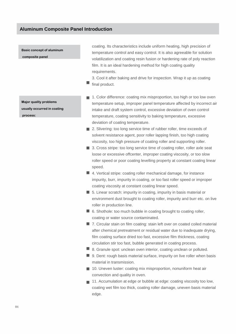
1. Color difference: coating mix misproportion, too high or too low oven
temperature setup, improper panel temperature affected by incorrect air
intake and draft system control, excessive deviation of oven control
temperature, coating sensitivity to baking temperature, excessive
deviation of coating temperature.
2. Slivering: too long service time of rubber roller, time exceeds of
solvent resistance agent, poor roller lapping finish, too high coating
viscosity, too high pressure of coating roller and supporting roller.
3. Cross stripe: too long service time of coating roller, roller axle seat
loose or excessive offcenter, improper coating viscosity, or too slow
roller speed or poor coating levelling property at constant coating linear
speed.
4. Vertical stripe: coating roller mechanical damage, for instance
impurity, burr, impurity in coating, or too fast roller speed or improper
coating viscosity at constant coating linear speed.
5. Linear scratch: impurity in coating, impurity in basis material or
environment dust brought to coating roller, impurity and burr etc. on live
roller in production line.
6. Shothole: too much bubble in coating brought to coating roller,
coating or water source contaminated.
7. Circular stain on film coating: stain left over on coated coiled material
after chemical pretreatment or residual water due to inadequate drying,
film coating surface dried too fast, excessive film thickness, coating
circulation stir too fast, bubble generated in coating process.
8. Granule spot: unclean oven interior, coating unclean or polluted.
9. Dent: rough basis material surface, impurity on live roller when basis
material in transmission.
10. Uneven luster: coating mix misproportion, nonuniform heat air
convection and quality in oven.
11. Accumulation at edge or bubble at edge: coating viscosity too low,
coating wet film too thick, coating roller damage, uneven basis material
edge.
04
Aluminum Composite Panel Introduction
Basic concept of aluminum
composite panel
Major quality problems
usually occurred in coating
process:
12. Surface blur: coating leveling uneven, nonuniform cooling usually for
PVDF FI-carbon coating.
13.Poor adhesive force: oil left over after pretreatment, invert film too
thick or uneven etc., inadequate baking, coating problem.
05
1.Plastic extruding machine is mainly composed of adjustable-speed
motor, reduction gear, screw, heating board and electrical apparatus
control part. Its function is to heat and melt plastic particle, which is
extruded by threaded rod and forms panel primarily. The panel is then
cooled and molded to plastic core panel as required by special three
roller evener. It includes material blender, particle feeding and drying
system, feed port chilled water system, threaded rod air cooling system
and Gas-axis system etc. (ratio of rod length to diameter shall be better
≧32).
2.Screw temperature control: screw is mainly divided into three
sections, feeding section, compressing section and plasticizing section.
Temperature control range shall usually be within 40-200℃.
3.Evacuating equipment: As PE particle itself contains water or may
be exposed to water in transportation and as water will absorb enough
amount of heat in threaded rod extrusion process, if there is no vacuum
evacuating equipment to boil off and to evacuate water, the water will
not get vaporized under high pressure inside the screw and will be
extruded together with plastic. As a result that the pressure of extruded
plastic rapidly drops from high pressure inside the screw to normal
pressure in air, water contained will immediately vaporize. At feeding
port of model and
Aluminum Composite Panel Introduction
Major quality problems
usually occurred in coating
process:
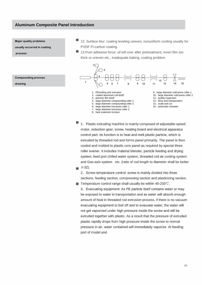
1、PEmelting and extrusion2、coated aluminum coil letoff3、polvmer film letoff4、large diameter compounding roller 15、large diameter compounding roller 26、large diameter hot-press roller 17、large diameter hot-press roller 28、heat treatment furnace
9、large diameter cold-press roller 110、large diameter cold-press roller 212、quality inspection13、drive and transporation14、scale and cut15、automatic unloader
1.Plastic extruding machine is mainly composed of adjustable-speed
motor, reduction gear, screw, heating board and electrical apparatus
control part. Its function is to heat and melt plastic particle, which is
extruded by threaded rod and forms panel primarily. The panel is then
cooled and molded to plastic core panel as required by special three
roller evener. It includes material blender, particle feeding and drying
system, feed port chilled water system, threaded rod air cooling system
and Gas-axis system etc. (ratio of rod length to diameter shall be better
≧32).
2.Screw temperature control: screw is mainly divided into three
sections, feeding section, compressing section and plasticizing section.
Temperature control range shall usually be within 40-200℃.
3.Evacuating equipment: As PE particle itself contains water or may
be exposed to water in transportation and as water will absorb enough
amount of heat in threaded rod extrusion process, if there is no vacuum
evacuating equipment to boil off and to evacuate water, the water will
not get vaporized under high pressure inside the screw and will be
extruded together with plastic. As a result that the pressure of extruded
plastic rapidly drops from high pressure inside the screw to normal
pressure in air, water contained will immediately vaporize. At feeding
port of model and
Compounding process
drawing
three rollers, vapor will pile up with water vapor continuously entering
to form larger bubble and then break up, which will leave many small
pits on trimmed core board surface. This will end up in failure of
normal compounding.
4.Three rollers: Based on preset clearance among three rollers,
grind, roll, cool and mold the molten plastic extruded out of forming
die to form panel of certain thickness. Core panel surface shall be
bright, flat without bubble and stripe. Panel thickness shall be uniform
and in close tolerance.
5.Polymer film: Polymer is directly used to bond plastic core board
and aluminum coil. It shall be flat when unwrapped. Tension control
shall be proper (it is required that rough side is in contact with
aluminum material).
6.Hot pressing compounding roller: Aluminum composite panel is
compounded in rolling process conducted by 1-3 group pressing-
heating roller. Heating roller transfers heat to aluminum panel by
close contact with two sides of aluminum panel. Aluminum panel
temperature rises and transfers heat to bonding material and core
board so that the latter both temperature rises rapidly to achieve
bonding of aluminum panel and core board. If roller temperature is
too high, the temperature on aluminum panel surface will also be too
high to affect coating quality. As FI-carbon coating is thermoplastic
resin and sensitive to temperature, it will be “scalded” and generate
blackspot on panel surface. That is the reason to choose roller of
larger diameter, which has enough heat capacity to ensure small
temperature variation and uniform heat exposure on panel surface.
Panel thickness shall be primarily formed at the first group of
compounding roller. Default clearance is generally 0.1-0.5mm larger
than panel thickness. Too big clearance will result in obvious panel
waveness, which is adverse to evenness in cold pressing and lowers
peel strength. Too small clearance will result in great elastic
deformation of core material. In this case, residual stress will also
affect panel shape and lower local peel strength.
7.Heating furnace: It is mainly used to remove residual stress and
adjust panel shape. The temperature shall be 20-50℃ higher than
panel temperature.
8.Cooling and forming roller group: It is mainly used to adjust panel
shape. The panel just compounded is at high temperature. At this
moment, glue between each layer is not cold set yet and bond
strength is still low. The glue need slow cooling. Otherwise, upper
and lower aluminum panel will shrink too fast to form lengthwise wave.
06
Aluminum Composite Panel Introduction
Compounding process
drawing

9.Cooling section: The section uses several groups of cooling fans up
and down, which not only guarantees cooling effects but also satisfies arc
scale requirement. Final panel temperature shall be controlled at 50 c
lower (included) than surface temperature.
10.Multiple groups of straightening machine: i.e. evener, which is
composed of three rollers. Panel shape can be adjusted by adjusting
clearance between upper and lower roller.
11.Quality inspection: Check and control product quality according to
national and enterprise standard.
12.Cut aluminum panel after driving. Size can be determined according
to order requirements.
13.Final product of Aluminum composite panel: Final product of
Aluminum composite panel, compounded and bonded with protective film
on the surface, can be warehoused for delivery after acceptance.
07
1.Inadequate peel strength: The major reasons include inadequate
technique temperature and heating time, improper clearance among
rollers, poor or polluted aluminum surface quality and poor polymer film
quality.
2.Bubbling: The major reasons include poor partial aluminum panel
surface quality, poor polymer film quality, infusible particle on core board
surface, inadequate temperature or air in material layers.
a.Press mark: The major reasons include that roller surface is
unclean and PE surplus material is carried to compounding rollers.
3.Scratch: The major reasons include unclean roller surface or
improper transportation.
4.Press pit and uneven panel surface: The major reasons include
impurities in PE material or inadequate temperature of roller of roller trio
machine.
5.Shell tuck: The major reasons include shell tuck on raw aluminum
coil, tension out of control or difference on both sides.
Aluminum Composite Panel Introduction
Compounding process
drawing
Major quality problems usually occurred in compounding
line:

08
It is usually classified according to its purpose, product function and
surface decorative effect.
(1) Classified by purpose
a) Aluminum composite panel for building curtain wall
Minimum thickness of upper and lower aluminum panel shall be no less
than 0.50mm and total thickness no less than 4mm. Aluminum material
shall conform to requirements of GB/T3880. It usually adopts 3000 and
5000 series of aluminum alloy panel and FI-carbon resin coating.
Thickness of the second coating layer shall be greater than or equal to
25um and that of the third layer 30um.
b) Aluminum composite panel for external wall decoration and ad.
Upper and lower aluminum panel shall be anticorrosive. Each thickness
no less than 0.50mm and total thickness no less than 4mm. It usually
adopts FI-carbon or polyester coating. Thickness of polyester coating
film shall be greater than or equal to 16um.
c) Aluminum composite panel for indoor decoration
Thickness of upper and lower aluminum panel is usually 0.50mm and
minimum thickness no less than 0.10mm and total thickness usually
3mm. It usually adopts polyester or crylic acid coating.
(2) Classified by product function
a) Common panel
This kind of panel has no special functional requirement and is used for
decoration in general cases. Performance index conforms to Aluminum
composite panel technical indicators other than special indicators.
b) Fireproof panel
Fire panel uses low smoke halogen-free inflaming retarding
polyethylene as core material. According to GB8624-1997, Building
Material Performance Classification Method, its fire safety performance
grade shall reach flame resisting grade (B1 grade) or non-inflammable
grade (A grade). Other performance indicators shall also conform to
Aluminum composite panel technical indicators. A grade refers to non-
inflammable material. B1 refers to flame resisting material. B2 refers to
flammable material. And B3 combustible material.
c) Antistatic panel
Antistatic panel uses antistatic coating to coat Aluminum composite
panel. Surface resistivity is under 109Ω, which is lower than that of
common aluminum panel. Accumulation of static electricity and dust
accumulation is
Aluminum composite panel
class and specification:
Aluminum Composite Panel Introduction
09
hard to appear on its surface. It has the effect of antistatic, dust proof
and self-cleaning and can avoid electric shock and fire due to static
electricity.
d) Antibiotic and mould proof Aluminum composite panel
This kind of panel uses antibiotic and mould proof coating to coat
Aluminum composite panel, which can control microbial activity and
growth and finally kill bacteria. It can restrain microbial activity and
growth and kill microbe to create a clean environment.
e) Chameleon Aluminum composite panel
Chameleon Aluminum composite panel has three layers of coating,
primer, top coat and clear lacquer. It is provided with all kinds of
superior physical mechanics performance of FI-carbon Aluminum
composite panel and ensures that no obvious chalking and color fading
appears on coating surface in 15 years. It adopts hi-tech coating
technology in baking to add imported flash pearly luster aluminum
powder in clear lacquer, which forms into a layer of film after high
temperature hardening. Post-coating surface has special decorative
effects. This product makes use of natural optical interference principle.
In the same illuminant and from different angles, Aluminum composite
panel surface will present different flash effect with multi colors and high
brightness. It is extensively used in indoor and exterior locations to be
specially represented in recreation places and marketplaces. The
surface effect cambered chameleon panel is more impressive.
f) Nanometer FI carbon Aluminum composite panel
At the same time of bearing all superior performance of FI carbon
Aluminum composite panel, the hi-tech nanometer coating technology
enables the product to have advantages of multiple performances over
traditional FI carbon Aluminum composite panel, like pollution resistance,
self cleaning and acid-alkali proof. It is a new type of building material
replacing the older generation. Compared with traditional FI carbon
Aluminum composite panel, the coating surface of this product has
perfect self-cleaning performance. Usually, external wall of Aluminum
composite panel is seriously polluted by dust and rain in half a year later.
Especially, the silicone sealant used in project, sometimes without strict
quality assurance, creates lots of black stain at seam location, which is
not only hard to be cleaned but also affects wall appearance. Now
nanometer FI carbon Alumi
Aluminum composite panel
class and specification:
Aluminum Composite Panel Introduction
09

10
num composite panel resolves this problem. Because of the low tensile force of coating itself,
worm mark is hard to adhere to its surface. Slight worm mark can be washed by rain to achieve
self cleaning. A large sum of cleaning and maintenance cost will be save every year. The simplest
identification method is to use oily marking chalk to scribble on the surface. No marks shall be left
on real product. Marks on common panel will be hard to be wiped out. The product can be
extensively used in top grade building curtain wall, and indoor and exterior decoration at star hotel,
conference center, airport and public utilities etc.
(3) Classified by surface decorative effect
a) Coating decorating board
It covers all kinds of decorative coating on aluminum panel surface, usually FI-carbon, polyester
and crylic acid coating etc.
b) Oxidation colored Aluminum composite panel
It uses anodic oxidation technology to treat aluminum alloy panel. Color includes rose red and
bronze etc.
c) Film decorating board
It is to adhere color stripe film to aluminum panel painted with primer or directly to degreasing
treated aluminum panel by bond under certain process conditions. Major brands include hill stripe
board and wooden stripe board etc.
d) Drawing block
The surface of aluminum alloy panel is wire drawing treated, usually including golden wire drawing
and silver wire drawing.
e) Mirror board
The surface of aluminum alloy panel is polished as it were a mirror.
Aluminum Composite Panel Introduction
Aluminum composite panel
class and specification:
Characteristics of Aluminum composite panel
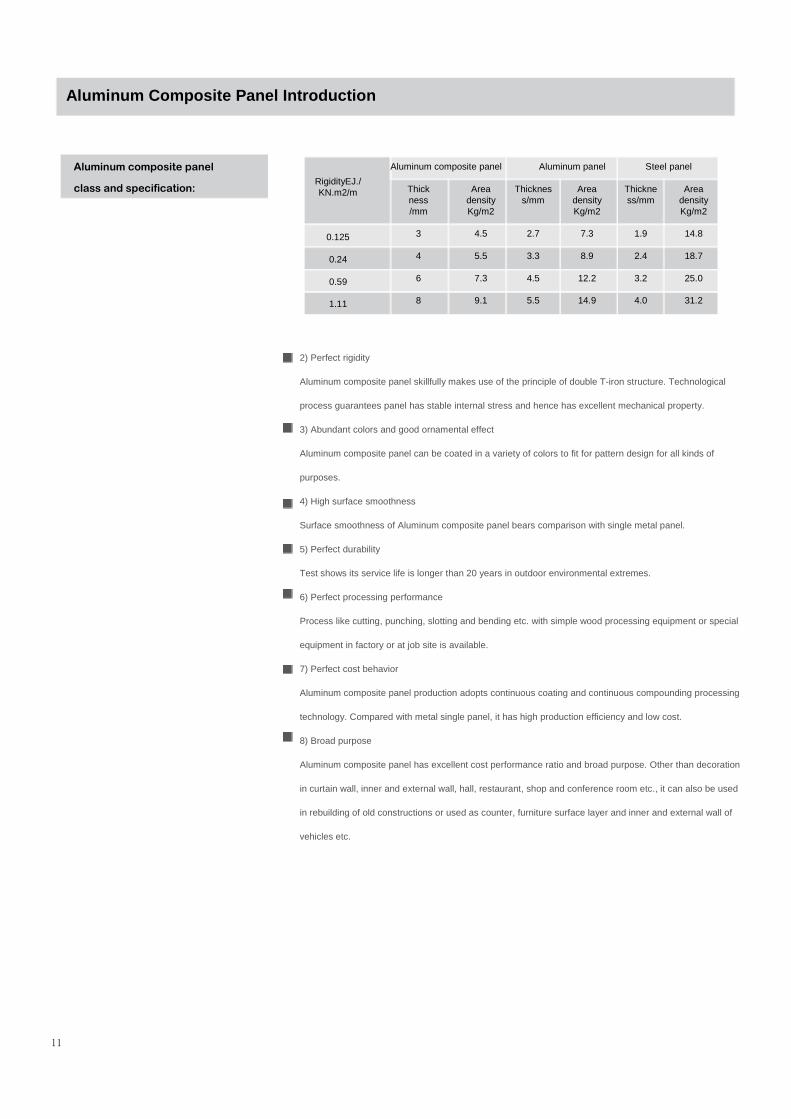
1) Light mass
Compared with aluminum (or other metals) of same rigidity or thickness, Aluminum composite panel
has lighter mass, thus greatly lowering architecture load.
Compare of rigidity, thickness and area density of different materials
Specification:
Common specifications of Aluminum
composite panel are:
Total thickness
2mm
3mm
4mm
5mm
6mm
Width
800mm
1220mm
1250mm
1500mm
1570mm
Length
1000mm
2440mm
3000mm
4000mm
6000mm
Other specifications and sizes can be arranged.
Aluminum composite panel of 1220mm×2440mm is called standard
panel in the trade.
Aluminum Composite Panel Introduction
11
Aluminum composite panel
class and specification:
2) Perfect rigidity
Aluminum composite panel skillfully makes use of the principle of double T-iron structure. Technological
process guarantees panel has stable internal stress and hence has excellent mechanical property.
3) Abundant colors and good ornamental effect
Aluminum composite panel can be coated in a variety of colors to fit for pattern design for all kinds of
purposes.
4) High surface smoothness
Surface smoothness of Aluminum composite panel bears comparison with single metal panel.
5) Perfect durability
Test shows its service life is longer than 20 years in outdoor environmental extremes.
6) Perfect processing performance
Process like cutting, punching, slotting and bending etc. with simple wood processing equipment or special
equipment in factory or at job site is available.
7) Perfect cost behavior
Aluminum composite panel production adopts continuous coating and continuous compounding processing
technology. Compared with metal single panel, it has high production efficiency and low cost.
8) Broad purpose
Aluminum composite panel has excellent cost performance ratio and broad purpose. Other than decoration
in curtain wall, inner and external wall, hall, restaurant, shop and conference room etc., it can also be used
in rebuilding of old constructions or used as counter, furniture surface layer and inner and external wall of
vehicles etc.
RigidityEJ./KN.m2/m
0.125
0.24
0.59
1.11
Thickness/mm
3
4
6
8
Area densityKg/m2
4.5
5.5
7.3
9.1
Area density Kg/m2
7.3
8.9
12.2
14.9
Thickness/mm
1.9
2.4
3.2
4.0
Area density Kg/m2
14.8
18.7
25.0
31.2
Thickness/mm
2.7
3.3
4.5
5.5
Aluminum composite panel Aluminum panel Steel panel
Raw material and technical
requirements
Aluminum material
Aluminum Composite Panel Introduction
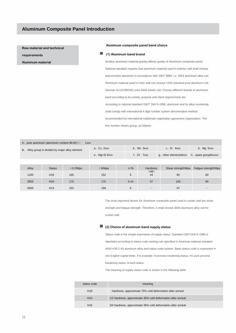
Aluminum composite panel band choice
(1) Aluminum band brand
Surface aluminum material greatly affects quality of Aluminum composite panel.
National standard requires that aluminum material used in exterior wall shall choose
anticorrosion aluminum in accordance with GB/T 3880, i.e. 3003 aluminum alloy coil.
Aluminum material used in inner wall can choose 1100 industrial pure aluminum coil.
German ALUCOBOND uses 5005 Aludur coil. Choose different brands of aluminum
band according to its variety, purpose and client requirements etc.
According to national standard GB/T 16474-1996, aluminum and its alloy numbering
shall comply with international 4 digit number system denomination method
recommended by international trademark registration agreement organization. The
first number means group, as follows:
The most important factors for Aluminum composite panel used in curtain wall are shear
strength and fatigue strength. Therefore, it shall choose 3003 aluminum alloy coil for
curtain wall.
(2) Choice of aluminum band supply status
Status code is the simple expression of supply status. Standard GB/T16474-1996 is
stipulated according to status code naming rule specified in American national standard
ANSI H35.1-93 aluminum alloy and status code system. Basic status code is expressed in
one English capital letter. For example: H-process hardening status, H1-pure process
hardening status, 8-hard status.
The meaning of supply status code is shown in the following table:
A、pure aluminum (aluminum content 99.00%) 1xxx
B、 Alloy group is divided by major alloy elementa、Cu 2xxx b、Mn 3xxx c、Si 4xxx d、Mg 5xxx
e、Mg+Si 6xxx f、Zn 7xxx g、other elements8xxx h、spare group9xxxvv
Alloy
1100
3003
5005
Status
H18
H16
H14
б0.2/Mpa
165
175
152
бb/Mpa
152
175
159
φ/%
5
5-14
6
Hardness(HB)
44
47
--
Shear strength/Mpa
90
105
97
Fatigue strength/Mpa
60
69
--
status code
H18
H24
H16
meaning
Hardness, approximate 75% cold deformation after anneal
1/2 hardness, approximate 35% cold deformation after anneal
3/4 hardness, approximate 35% cold deformation after anneal
12

13
(3) Dimensional deviation of aluminum band
Raw material and technical
requirements
Aluminum material
Aluminum Composite Panel Introduction
Product brand, status and specification for Aluminum composite panel are shown in the
following table:
Number Status
1100
3003
5005
H18
H16、H14、H28、H24
H16、H14、H26、H24
Thickness/mm
0.20~1.00
0.20~1.00
0.20~1.00
Width/mm
1000~1580
1000~1580
1000~1580
Inside diameter of paper tube/mm
400or500
Specification
Dimensional deviation of aluminum band is shown in the following table:
Thickness/mm
0.20~0.30
>0.30~0.50
>0.50~1.00
Thickness deviation/mm
±0.015
±0.020
±0.025
Width deviation/mm
±1.5
(4) Aluminum band quality requirements:
Except for satisfying mechanical properties and supply status etc., aluminum band shall also
satisfy the following requirements:
(1) Paper sleeve length shall not be less than width of the band but no greater than 10mm.
(2) Side camber in 2m section at random of the band shall be no greater than 3mm.
(3) When spread on platform as desired, clearance between band and plane shall be no greater
than 3mm and ripple marks in every one meter no more than 3.
(4) At band end face, string of coils is no greater than 2mm and tower-shaped no greater than
5mm (except for 5 circles on both ends).
(5) Appearance quality
a.Band surface shall be well processed and texture uniform, flat and smooth. Cracks,
perforated pore, crack leak, pinch mark, corrosion, press pit, pine branched pattern, metal or
nonmetal press-in are not allowed on surface.
b.No defects like obvious across grain, black stripe, dark and light stripe, obvious oil stain,
serious scratch and periodic print etc. that may affect its service are allowed on band surface.
c.Band shall be wrapped tight and tidy without cracked edge, burr and knocking damage.
d.Coil-down are not allowed.
e.No joints on band are allowed.
Note: Visually inspect aluminum band appearance quality. Magnifier is unnecessary.
Aluminum Composite Panel Introduction
Raw material and technical
requirements
Aluminum material
14
Raw material and technical
requirements
Core material
Core material of Aluminum composite panel formerly uses PVC and now PE. The latter is provided
with many advantages, such as non toxicity, good factory behavior, wide molding technology
scope, extremely low water absorption, perfect chemical stability, low density, low price and
extensive raw material source etc.
Low density PE is produced by high-pressure method, hence also called high-pressure
polyethylene. It is to compress ethane under 150-300Mpa high-pressure conditions and to use
oxygen or peroxide as initiator to polymerize ethane at 180-200℃ temperature according to free
radical polymerization reaction mechanism. The molecule has long and short branched chain in low
density, which usually is 0.910-0.925g/cm3. Crystallinity is 55-65%. Thereby it is called low density
polyethene, LDPE for short. Among all kinds of PE, LDPE is the one only that contains long
branched chain. Its processability, flexibility and transparency are superior to all other kinds of PE.
Its melting point is 105-115℃ and breaking elongation 300-600%.
In PE production process, it is to mainly check items like density, cleanness, solution index,
molecular weight distribution, vicat softening point and crystallinity etc.
Density inspection usually adopts weight method and gradient tube method. The latter is specified
in national standard GB 1033-1986.
Cleanness has two indexes, color particle and impurity. Usually visual inspection will do.
Solution index inspection makes use of solution flow rate meter. Heat solution to 190℃. Check
mass of solution passing moedel in every 10 minutes (8/10 minutes) under 2.16kg pressure.
vicat softening point inspection is conducted by vicat softening point gauge.
Performance inspection:

Aluminum Composite Panel Introduction
Raw material and technical
requirements
Core material
It is to measure the temperature when piercing depth is 1mm under specified conditions. The unit is
℃. Sample requirements: thickness 3-6mm and length and width greater than 10mm each.
Molecular weight distribution and crystallinity are usually skipped at factory.
Most factory uses recycled PE to lower production cost, which is called processing scrap.
Processing scrap is leftover material of other products, such as cutting edge of film and panel
material etc. The processing scrap, though heated several times, has not been exposed in outdoor
sunlight for long time. Its solution index has no much change. The strength retention rate is
generally above 90%. It can directly go into production only by adding 0.2% antioxidant. Tests show
that it can also be directly used without adding any antioxidant.
1、PE for common Aluminum composite panel
Test method
(1) Appearance and color
Sample 200g from product at random and conduct visual inspection in natural light.
(2) Solution index and density
Set up temperature and pressure. Raise temperature until relatively stable and add in sample
material. Choose range and enter into waiting state. Use cutter to take sample according to
specified time interval and weigh the sample. Calculate solution index (MFR) and solution density
(ρ) by the following formula: MFR=600×m÷t(g/10min)
In which: MFR—solution flow rate (g/10min)
m—sample average mass (g)
t—time that the sample flow out of model (s)
ρ=14×m÷L(g/cm3)
In which: ρ—solution density (g/cm3)
m—sample average mass (g)
L—travel 5.4/6.35/(3.17mm)
(3) Water content
Put PE material in weighing bottle. Take 5g samples by analytic balance with 0.1mg truth. Dry it in
100-105±2℃ constant temperature oven for 2 hours. Remove the sample to drier and cool to
room temperature for weighing.
15
Aluminum Composite Panel Introduction
Type, performance and
application of Aluminum
composite panel
A=(W1-W2)÷W1×100%
In which:
A—water content, %
W1—sample mass before drying, g
W2—sample mass after drying, g
(4) Vicat softening point
Use vicat gauge to measurevicat softening point, which is usually controlled at about 97 c
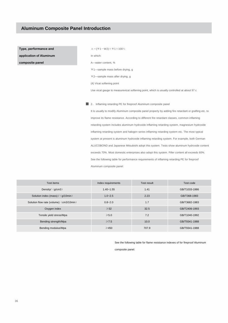
2、 Inflaming retarding PE for fireproof Aluminum composite panel
It is usually to modify Aluminum composite panel property by adding fire retardant or grafting etc. to
improve its flame resistance. According to different fire retardant classes, common inflaming
retarding system includes aluminum hydroxide inflaming retarding system, magnesium hydroxide
inflaming retarding system and halogen series inflaming retarding system etc. The most typical
system at present is aluminum hydroxide inflaming retarding system. For example, both German
ALUCOBOND and Japanese Mitsubishi adopt this system. Tests show aluminum hydroxide content
exceeds 70%. Most domestic enterprises also adopt this system. Filler content all exceeds 60%.
See the following table for performance requirements of inflaming retarding PE for fireproof
Aluminum composite panel:
16
Test items
Density/(g/cm3)
Solution index (mass) /(g/10min)
Solution flow rate (volume)(cm3/10min)
Oxygen index
Tensile yield stress/Mpa
Bending strength/Mpa
Bending modulus/Mpa
Index requirements
1.40~1.55
1.0~2.5
0.8~2.0
≥32
≥5.0
≥7.5
≥450
Test result
1.41
2.23
1.7
32.5
7.2
10.0
707.9
Test code
GB/T1033-1986
GB/T368-1983
GB/T3682-1983
GB/T2406-1993
GB/T1040-1992
GB/T9341-1988
GB/T9341-1988
See the following table for flame resistance indexes of for fireproof Aluminum
composite panel:

Aluminum Composite Panel Introduction
Type, performance and
application of Aluminum
composite panel
Decorative surface of Aluminum composite panel is to cover different coating on aluminum
panel surface to satisfy demands of different users. At present, domestic Aluminum composite
panel production mainly employs three kinds of coating systems, polyester, crylic acid and FI-
carbon coating, which are used as primer, final coating, black out paint and back paint for
Aluminum composite panel.
(1) Primer
Key function of primer is to improve finish coating adhesive force on aluminum panel. Therefore
it is required that primer paint film is perfectly adhesive to both base material and finish coating
film. Film thickness is usually 7-10μm. Except for good mechanical properties, paint film shall
also be of excellent corrosion protection. Primer usually uses epoxy coating. Else varieties
include polyester and polyurethane as well as FI-carbon resin coatings.
(2) Finish coating
Finish coating has multiple colors to suit for customer individuality. Different types of coatings
have different colors and properties. For example, PE has good brightness and vivid colors.
PVDF is fadeless for as long as 20 years. Nanometer board is of good brightness in addition to
all PVDF properties. Its self-cleaning function is the most important and a new technology to
Aluminum composite panel.
Polymer film uses American Du pont raw material. Polymer content is usually above 70%, which
guarantees fastness of aluminum and PE core material. External wall service life is normally
about 15-20 years.
17
Raw material and technical
requirements
Coating
Raw material and technical
requirements
Polymer film
Test items
Minimum value of burning residue length/mm
Average value of burning residue length /mm
Flue gas temperature, ℃
Flame tip height /mm
Smoke density grade
Detection standard
GB/T8625-88
GB/T8625-88
GB/T8625-88
GB/T8626-88
GB/T8625-88
Technical requirements
>0
≥150
≤200
<150
≤75

18
Aluminum Composite Panel Introduction
Type, performance and
application of Aluminum
composite panel
1. Type: Aluminum composite panel is a generic term, including many types. It is usually classified
by purpose, surface coating, color, surface pattern, specification and size, special function, surface
treatment method and overcoating etc., which has been discussed in the foregoing.
2. Performance
Aluminum composite panel is a kind of laminar composite material, which compound precoated
aluminum panel and plastic core material together by polymer binding material under high
temperature and certain pressure conditions. It not only keeps main characteristics of raw
components like aluminum panel and plastic etc. but also bears new characteristics that raw
components lacks. The integral performance of Aluminum composite panel is not a simple sum or
average of the performance its components. It involves composition effect, which is virtually the
result that component materials and the interface these materials formed interact, mutually depend
and complement with each other.
Composite material has the following interface effect:
1) Transmission effect. Interface can transfer force, i.e. transfer external force to every composite
material as a bridge among basis materials.
2) Blocking effect. Combination interface can prevent cracks from expanding, stop material damage
and reduce stress concentration.
3) Discontinuity effect. Discontinuity of physical properties and boundary friction will occur on
interface, behaving as electricity resistance, heat tolerance and dimensional stability etc. properties
of composite material.
4) Scattering and absorption effect. Light wave, sound wave, thermoelastic wave and shock wave
are scattered or absorbed by interface, behaving as heat insulation, sound insulation, mechanical
shock resistance and thermal shock resistance etc. properties of composite material.
5) Inductive effect. The phenomenon occurs when contact surface of two kinds of composite
materials changes because of inductive effect, such as strong elasticity, low expansibility, impact
resistance and heat resistance etc.
The interface performance generated by the above interface effect and the material property of
aluminum and plastic, which are the two main composite materials of Aluminum composite panel,
as well as surface coating performance, form excellent characteristics of Aluminum composite
panel, such as flatness, rigidity and processability etc.
Aluminum Composite Panel Introduction
Type, performance and
application of Aluminum
composite panel
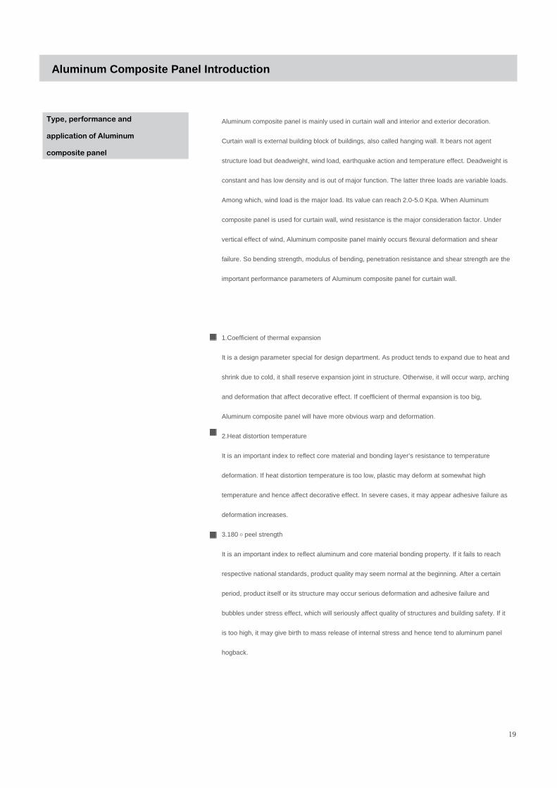
Aluminum composite panel is mainly used in curtain wall and interior and exterior decoration.
Curtain wall is external building block of buildings, also called hanging wall. It bears not agent
structure load but deadweight, wind load, earthquake action and temperature effect. Deadweight is
constant and has low density and is out of major function. The latter three loads are variable loads.
Among which, wind load is the major load. Its value can reach 2.0-5.0 Kpa. When Aluminum
composite panel is used for curtain wall, wind resistance is the major consideration factor. Under
vertical effect of wind, Aluminum composite panel mainly occurs flexural deformation and shear
failure. So bending strength, modulus of bending, penetration resistance and shear strength are the
important performance parameters of Aluminum composite panel for curtain wall.
1.Coefficient of thermal expansion
It is a design parameter special for design department. As product tends to expand due to heat and
shrink due to cold, it shall reserve expansion joint in structure. Otherwise, it will occur warp, arching
and deformation that affect decorative effect. If coefficient of thermal expansion is too big,
Aluminum composite panel will have more obvious warp and deformation.
2.Heat distortion temperature
It is an important index to reflect core material and bonding layer’s resistance to temperature
deformation. If heat distortion temperature is too low, plastic may deform at somewhat high
temperature and hence affect decorative effect. In severe cases, it may appear adhesive failure as
deformation increases.
3.180оpeel strength
It is an important index to reflect aluminum and core material bonding property. If it fails to reach
respective national standards, product quality may seem normal at the beginning. After a certain
period, product itself or its structure may occur serious deformation and adhesive failure and
bubbles under stress effect, which will seriously affect quality of structures and building safety. If it
is too high, it may give birth to mass release of internal stress and hence tend to aluminum panel
hogback.
19

20
Aluminum Composite Panel Introduction
Type, performance and
application of Aluminum
composite panel
4.Penetration resistance and shear strength
It is one of the important parameters for designer’s structural design. It mainly reflects key
properties of raw material and the value is determined by raw material.
5.Bending strength and modulus of bending
Bending is one of the major stress patterns of Aluminum composite panel. It basically means its
fatigue resistance and wind load received when aluminum panel is bent. The better the bending
strength and modulus of bending are, the stronger its wind pressure resistance and longer its
service life.
Bond area of aluminum panel and plastic material is the weak link of shear damage. Therefore
180оpeel strength is an important performance index of Aluminum composite panel.
Characteristics of face panel coating include coating thickness, hardness, brightness, impact
toughness, adhesive force, attrition resistance, boiling water resistance and chemical stability etc.
Therein chemical stability includes resistance to soiling, oil resistance, acid and alkaline resistance,
solvent resistance and wash resistance etc. Resistance to soiling reflects its self-cleaning capability
in application. Oil resistance, acid and alkaline resistance reflects its resistance to corrosion.
Solvent resistance presents coating hardening degree, which affects coating quality and service life.
Wash resistance index guarantees that product will not be adversely affected by cleaning after
application.
Atmospheric exposure test can be divided into two test methods, outdoor insolation test and
accelerated aging test.
Durability is an important property of aluminum plastic panel, which includes saltfog resistance
and weathering resistance. Saltfog resistance index guarantees product employment in coastal
area. Weathering resistance means how the product can resist weathering destructiveness.
Durability of aluminum plastic panel mainly relies on its surface coating performance. There are
lots of elements to affect surface coating performance, including coating technology and
thickness except for its brands
Durability

Aluminum Composite Panel Introduction
Type, performance and
application of Aluminum
composite panel
and quality. To ensure its durability satisfies requirements, external wall coating shall adopt FI-
carbon resin with 70% FI-carbon contents. Coating thickness of inner and external wall shall be
greater than 16μm and 25μm accordingly.
Weathering resistance test include two methods, outdoor insolation test and accelerated aging test.
Application area of Aluminum composite panel
Aluminum composite panel is extensively used in many fields, including the following major aspects.
1) Building curtain wall
2) Exterior decoration
3) Interior decoration
4) Old building external wall refitting and revamping
5) Signboard, designation panel and ad signboard
6) Fence wall, balcony, device cell and indoor compartment
7) Vehicle interior and exterior decoration
21

20
Aluminum Composite Panel Introduction
The excellence of
aluminum-plastic signboard
1、Smooth Surface, Rich Texture, Various Color : We can provide the RAL and Pantone colors,
including the high gloss, matt gloss, brushed, mirror, wooden finished board and customized as
your requirement.
2、Various Designs and Length : Width is from 1000mm to 1550mm. Length could be customized
as your requirement beyond the standard size accord with the processing techniques, no need to
piece together.
3、Simple Processing, Various Modalities : It could be processed to various forms and has much
process such as cutting, bending, punching, sticking and painting.
4、Lowest Rate of Expand and Shrink : Dimensions stable, does not expand and shrink
under the adverse circumstance, with wide temperature resistance (-50℃~80℃)
5、High adhesive intensity : The American DuPont technology could insure the board would not
distortion, cockle, shelling during the cutting and bending.
6、Environment friendly : It is the green building material, no radiation and pollution.
7、Superior weather-resistance and rub-resistance: Surface treatment with high-grade
ultraviolet-resistant polyester paint (ECCA) request, guarantee 8-10 years; if use the KYNar500
PVDF paint, guarantee 15-20 years.
8、Superior Rigidity : Unbelievable light with amazing hardness.
IBOND Signboard Technical Data
Panel thickessThickness of AluminiumLayersWeight
Technical Properties:
Section ModulusRigidity(POsson’rationµ =0.3)Alloy of Aluminium LayersModulus of ElasticityTensile Strength of Aluminum0.2% Proof StressElongationLinear Thermal EXpansion
Thermal Prope rties:
Thermal ResisanceHeat Transition CoetticientRange of Application
WE.1
E
RU
(mm)(kg/m2)
(cm3/m)(KNcm3/m)
(N/mm2)(N/mm2)(N/mm2)(%)
(m2K/m)(w/m2k)oC
2mm 3mm 4mm 6mm 0.30
2.90 3.80 4.75 6.60
0.51 0.81 1.11 1.71 345 865 1620 3840
Rm:145-185Rp0,2: 110 - 175A50>3%2. 0mm/m (100. C temperture difference)
0.0047 0.0080 0.0113 0.0180 5.72 5.61 5.50 5.30
-50~+80
Time Color Variation Chalking
5 year
7 year
10 year
ECCA/T3 ASTMD-2244-89
dE
3
3
4
ASTMD-659-86
Index: 1-10
8
7
7
dE 3= Very Good Index 10= No ChalkingdE 4= Good Index 1= Strong ChalkingdE 5= Satisfactory
Gewicht (kg/m2)WeightPaids
Rigidity(mm)

Aluminum Composite Panel Introduction
Feature 1、Weather-resistance:Superior weather-resistance and ultraviolet(UV) resistance, acid-resistance
and alkali-resistance, suitable for all natural environments. It can be guaranteed 15 years without
change of color, its temperature range from-40 to 80;
Quality
The fully automatic coil coating process is computer controlled throughout all the stages. Coating
quality is tested according to the standards established by the ECCA . The long-term durability of
coatings can be compared by measuring
·Color change ·Gloss retention ·Chalking
The superiority of PIVOT Ultra-cote UV resistant lacquer systems (PVdF) is shown in the three
graphs. The values indicated are taken from tests conducted by the American Coil Coating
Association (NCCA) on lacquered surfaces which were exposed to the extreme climatic conditions
of South Florida for several year
2、Economic:The ACP use high quality aluminum sheet and plastic core, it's light to transport,
saving the project time.
3、Light weight:No pollution, is green building decorative material; Can be easily processed and
installed; Light weight, good
strength and flexibility
4、Environment: Superior aging resistance, no coating change, no pollution, anti-acid, and anti-
alkali, solvent resistance.
5、Color:We can provide 50 kinds of color for your choose. but any color and size are available
according to your need.
6、Strength:The ACP use high quality aluminum, has greatly enhanced the strength of ACP,
ensuring that the curtain wall wind pressure resistance, prevention of leakage, and the shock effect.
7、Surface smooth:The fire-resist ACP provide superior and smooth surface, satisfying the
modern building on the pursuit of high-perception. The ACP's surface is much more smooth than
aluminum sheet.
23
IBOND compared with the solid aluminum panel
Required thickness and actual weights of panels with same rigidity
Rigidity Section Modulus Thickness Weight
E.J W
125 kn cm2/m 1.25 cm3/m 3 mm 4.5 kg/m2
2400 kn cm2/m 1.75 cm3/m 4 mm 5.5 kg/m2
Aluminu
Weight Thickness
2.7 mm 7.3 kg/m2
3.3 mm 8.9 kg/m2
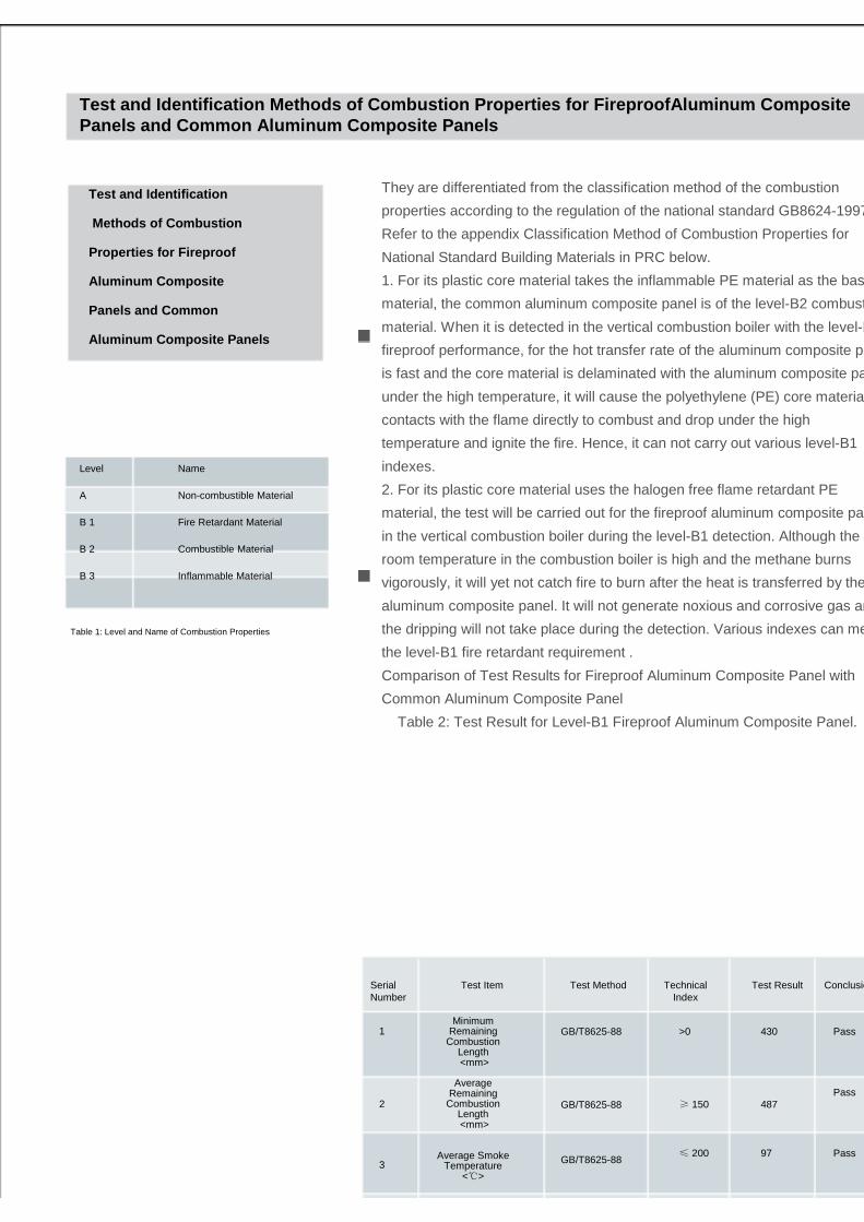
They are differentiated from the classification method of the combustion
properties according to the regulation of the national standard GB8624-1997.
Refer to the appendix Classification Method of Combustion Properties for
National Standard Building Materials in PRC below.
1. For its plastic core material takes the inflammable PE material as the base
material, the common aluminum composite panel is of the level-B2 combustible
material. When it is detected in the vertical combustion boiler with the level-B1
fireproof performance, for the hot transfer rate of the aluminum composite panel
is fast and the core material is delaminated with the aluminum composite panel
under the high temperature, it will cause the polyethylene (PE) core material
contacts with the flame directly to combust and drop under the high
temperature and ignite the fire. Hence, it can not carry out various level-B1
indexes.
2. For its plastic core material uses the halogen free flame retardant PE
material, the test will be carried out for the fireproof aluminum composite panel
in the vertical combustion boiler during the level-B1 detection. Although the
room temperature in the combustion boiler is high and the methane burns
vigorously, it will yet not catch fire to burn after the heat is transferred by the
aluminum composite panel. It will not generate noxious and corrosive gas and
the dripping will not take place during the detection. Various indexes can meet
the level-B1 fire retardant requirement .
Comparison of Test Results for Fireproof Aluminum Composite Panel with
Common Aluminum Composite Panel
Table 2: Test Result for Level-B1 Fireproof Aluminum Composite Panel.
Test and Identification Methods of Combustion Prope rties for FireproofAluminum Composite Panels and Common Aluminum Composite Panels
Test and Identification
Methods of Combustion
Properties for Fireproof
Aluminum Composite
Panels and Common
Aluminum Composite Panels
Level Name
A Non-combustible Material
B 1 Fire Retardant Material
B 2 Combustible Material
B 3 Inflammable Material
Table 1: Level and Name of Combustion Properties
Serial Number
Test Item Test Method Technical Index
Test Result Conclusion
1
2
3
Minimum Remaining
Combustion Length<mm>
Average Remaining
Combustion Length <mm>
Average Smoke Temperature
<℃>
GB/T8625-88
GB/T8625-88
GB/T8625-88
>0
≥ 150
≤ 200
Pass
Pass
Pass
Pass
430
487
97

From the perspective of the color for the aluminum composite panel core
material, the color of the Real level-B1 Fireproof Aluminum Composite Panel is
usually white for its core material uses the halogen free flame retardant PE
material and includes a large number of inorganic fire retardants after the
activation processing. From the perspective of the appearance, the peel surface
and section of the Real level-B1 Fireproof Aluminum Composite Panel are
white, while the peel surface and section of the counterfeit level-B1 Fireproof
Aluminum Composite Panel are gray white and dark white. The common
Aluminum Composite Panel usually uses the black core material. However, the
vicious competition in the whole Aluminum Composite Panel industry causes
various manufacturers use a large number of PE film recycling materials
(regenerated materials) for reducing their cost in recent years. Hence, some PE
material in the current market is white, which makes the common Aluminum
Composite Panel with white peel surface and section of the core material
counterfeit the fireproof Aluminum Composite Panel.
Type of Fireproof Aluminum Composite Panel in Current Market
1. Counterfeit Level-B1 Fireproof Aluminum Composite Panel: The core
material is halogen flame retardant, whose color is usually dark gray white
Test and Identification
Methods of Combustion
Properties for Fireproof
Aluminum Composite
Panels and Common
Aluminum Composite Panels
Table 3: Test Result for Level-B2 Common Aluminum Composite Panel
Serial Numbe
r
1
2
3
4
5
Test Item
Minimum Remaining Combustion Length
<mm>
Average Remaining Combustion Length
<mm>
Average Smoke Temperature
<℃>
Height of Flame<mm>
Smoke Density Rating(SDR)
Test Method
GB/T8625-88
GB/T8625-88
GB/T8625-88
GB/T8626-88
GB/T8627-1999
Technical Index
>0
≥150
≤200
<150
≤75
Test Result
0
0
620
15
28
Conclusion
Failed
Failed
Failed
Failed
Failed
Differentiating Fireproof Aluminum Composite Panel,
Counterfeit Fireproof Aluminum Composite Panel and
Common Aluminum Composite Panel from Appearance Color
Test and Identification Methods of Combustion Prope rties for FireproofAluminumComposite Panels and Common Aluminum Composite Pane ls

and the density is rather lower, so it can not meet the requirement for the
fireproof and environmental protection of the building material in the market.
2. Real Level-B1 Fireproof Aluminum Composite Panel: The core material is
halogen free flame retardant, whose color is usually white and the density is
rather higher, so it can meet the requirement for the fireproof and
environmental protection of the building material in the market.
The halogen flame retardant material refers to add the polymers with the
halogen or halogen flame retardants into the PE plastics and be equipped
with the noxious antimony compound, and then produce this material by
simple physical mixing method. Halogen – The antimony can provide
obvious flame retardant effect. However, once the fire hazard takes place, it
is easy to generate a large number of noxious carbon monoxide and
hydrogen halide gas with strong corrosion for the high temperature
decomposition and combustion, and cause the secondary pollution for the
environment and is disadvantage of the environment requirement for current
building material.
The halogen free flame retardant material refers to the flame retardant
composite material that is produced by adding the halogen free flame
retardant and other flame retardant intensifier without halogens into the
grafting modified PE, and using special patent technology and high efficient
plasticized mixing technique. Once the fire hazard takes place, the speed of
catching fire to burn is slow, it will not decompose the noxious gas and the
melting material will not drip. In this way, it will provide the personnel in the
fire hazard field with enough escaping time and doesn’t pollute the field.
Hence, the personnel in the fire hazard field will not be choked to die for the
absorption of much noxious gas.
To judge the Fireproof Aluminum Composite Panel, people like to burn its
core material by the lighter. During the slow combustion of the core material,
you will detect the combustion time is short for the core material of the
counterfeit level-B1 Fireproof Aluminum Composite Panel. However, it will
generate a large number of black smoke accompanying with fierce pungent
smell, and the melting material will cause the dripping.
For the halogen free core material of the Real level-B1 Fireproof Alumi
Test and Identification Methods of Combustion Prope rties for FireproofAluminumComposite Panels and Common Aluminum Composite Pane ls
Test and IdentificationTest and IdentificationTest and IdentificationTest and Identification
Methods of Combustion Methods of Combustion Methods of Combustion Methods of Combustion
Properties for Fireproof Properties for Fireproof Properties for Fireproof Properties for Fireproof
Aluminum Composite Aluminum Composite Aluminum Composite Aluminum Composite
Panels and Common Panels and Common Panels and Common Panels and Common
Aluminum Composite PanelsAluminum Composite PanelsAluminum Composite PanelsAluminum Composite Panels
num Composite Panel, the halogen free material will not generate dense smoke
and the smoke is slight, there is not any pungent smell, and the combustion
speed is slow. There is no the dripping phenomenon during the combustion.
Furthermore, its surface will generate dense oxide to cover the combustion
surface of the core material and isolate it from the oxide in the air during the
combustion. At the same time, it will generate the moisture by the reaction
during the combustion, to reduce the combustion temperature and achieve the
flame retardant and self extinguishing.
Test and IdentificationTest and IdentificationTest and IdentificationTest and Identification
Methods of Combustion Methods of Combustion Methods of Combustion Methods of Combustion
Properties for Fireproof Properties for Fireproof Properties for Fireproof Properties for Fireproof
Aluminum Composite Aluminum Composite Aluminum Composite Aluminum Composite
Panels and Common Panels and Common Panels and Common Panels and Common
Aluminum Composite PanelsAluminum Composite PanelsAluminum Composite PanelsAluminum Composite Panels
Test and Identification Methods of Combustion Prope rties for FireproofAluminumComposite Panels and Common Aluminum Composite Pane ls
As is well known that for the ingredient of the super weather resistance
fluorocarbon coats, the PVDF content in the total coats must be equal to or
greater than 70 percent. It can ensure the quality of the fluorocarbon coats and
the long beauty of the buildings only when above conditions are met. However,
there are some PVDF coats with low cost and poor quality in the market.
Although it is hard to differentiate these coats from Hylar5000 coats in the short
run, the weather resistance of these coats can not match with Hylar5000 coats
and it will also loss the beauty and shorten the life of buildings as well as
increase the cost for the recoating and maintenance. Hence, it draws the
construction industry’s attention.
In this case, Solvay researches on various ingredients of the fluorocarbon coats
in depth and puts forward three different methods to determinate the content of
PVDF in coatss, so as to protect the benefit of its customers. These methods
include the traditional quantitative determination – solubility, the fusion point
quantitative determination – using the Differential Scanning Calorimeter
(DSC),and the pyrolytic quantitative determination in the inert gas – using the
Thermogravimetric Analysis (TGA).
There are some advantages and disadvantages of three determination methods,
so they can be combined with each other to obtain an accurate result. The
following will describe three determination methods in details.
Test Method of PVDF Fluorocarbon Resin Content
Test Method of PVDF
Fluorocarbon Resin
Content
Traditional Quantitative
Determination MethodIn addition to two resin ingredients such as PVDF and PE, the PVDF
fluorocarbon coats also include the pigment for the beauty and some additives
for changing the operation performance. These ingredients have different
solubility in the organic solvents.
The pigment is not dissolved in the organic solvents fully.
PVDF is only dissolved in N-methylpyrolidone, dimethylsulfoxide, N, N-
dimethylacetamide and N, N-dimethylfornmmide.
The Polyacrylate (PA) can be dissolved in PVDF as well as other common
organic solvents.
The traditional quantitative determination method is to determine the content
according to different solubility of various coat ingredients. Fig.4-15 shows the
flow chart of traditional quantitative determination method, which has been used
for a long time. The main source of error is the
(1) Traditional Quantitative Determination Method

insoluble polymer PE. Furthermore, the use of the organic pigment may also
generate the error. The disadvantage of this method is that it needs a large
number of coats and is hard to collect the sample and determine the ingredient
for a long time.
Test Method of PVDF Fluorocarbon Resin Content
Traditional Quantitative
Determination Method
Fig.4-15 Flow Chart of Traditional Quantitative Determination Method
(2) Fusion Point Quantitative Determination Method
In general, the fusion point of the crystal will reduce with the content of the
soluble matter, and the reduced degree can be evaluated by the
thermodynamic formula. The crystallization behavior of the polymer is more
complex than general crystals for the possibility of inter-solubility with other
polymers will reduce greatly with the increasing of the molecular weight. The
basic principle of the inter-solubility for the polymer is the same as that of
common matters, and the basic thermodynamic formula is shown as follows:
Fusion Point Quantitative
Determination Method
The free energy (ΔGmix) must be the negative value and ΔSmix is usually the
negative value. Hence, it will generate negative free energy only when the
mixed heat is high. Under the condition of inter-solubility with the coplasticizer
the fusion point of the crystal plastics can be expressed by the fusion point
reduction formula of the Flory.
This formula is derived to apply to two soluble plastics and the modified fusion
point reduction formula is used to evaluate the fusion point of PVDF in the inter
soluble mixture of its PE. This principle is simplified as follows:
Non-solvent of PVDF PVDF+Aoxiliary Agent
Solvent,NMP PVDF+PA+Auxiliary Agemt
Coats
Filtering
PA SolutionFiltering
Pigment

Where,V1 is the volume ingredient of the non-crystal plastics in the inter-
soluble mixture.
Tm0 is the fusion point of the pure crystal plastics.
Tm is the fusion point of the crystal plastics in the inter-soluble mixture.
V1u is the mole volume of the non-crystal plastics unit.
V2u is the mole volume of the crystal plastics unit.
ΔH2u is the full crystallization heat of the crystal plastics.
χ12 –s the Flory-Huggins parameters.
The ΔH2u of PVDF is determined to be 1.6kcal/mole (25cal/g or 104.2j/g)
by using the fusion point reduction principle of original Flory. Under the
temperature 160℃, the parameter B is equal to -2.98 cal/cm3. After the Tm0
and Tm are determined, the content of PVDF in coats can be obtained.
To verify the reliability of the fusion point quantitative determination method,
Fig.4-16 collects the material of PVDF fusion point reduction from the
literature. The fusion point of the original PVDF is higher than that of Hylar
5000 in the literature. However, Fig.4-16 demonstrates the fusion point
reduction principle is practicable. To make the determination method simple,
Fig.4-17 provides the relationship between the fusion point reduction degree
of PVDF (ΔTm= Tm0- Tm) and the content. You can evaluate the ingredient
of coats if only you determine the fusion point for two times.
The fusion heat of PVDF in the inter-soluble mixture can also assist in the
fusion point determination method. The DSC can both determine the fusion
point and crystal point and provide the fusion heat. Fig.4-18 shows the
relationship between the relative fusion heat and the ingredient of PVDF in
coats. The relative fusion heat is equal to the fusion heat of PVDF in the
inter-soluble mixture divided by the fusion heat of the pure PVDF.
The principle of the fusion point quantitative determination method is based
on two inter-soluble plastics, and the PVDF is inter-soluble with several
plastics, for example, the PE with high content of the methyl methacrylate
unit. Some manufacturers add the coagulated PE to improve the hardness or
change other properties. Hence, this may reduce its inter-solubility with
PVDF. In this case, the fusion point of PVDF may be high,
Test Method of PVDF Fluorocarbon Resin Content
The content of PVDF in the plastics.%
Fig.4-16 Effect of PE Content on Fusion Point of
PVDF in Mutual Mixture
● PVDF/PMMA Tempering Mixture
▲ PVDF/PMMA Melting Mixture;
◆ PVDF/PMMA Solution Dry Mixture;
■ PVDF/PEMA Tempering Mixture;
X PVDF/PMMA Tempering Mixture
Fig. 4-3-10 Relationship between Fusion Point Reduction Degree of PVDF (ΔTm= Tm0- Tm) and Its Content
and it will not be used individually if the fusion point is reduced, so the fusion
specific heat becomes a necessary determination tool. Especially, if the coats
consist of plastics that are not inter-soluble with PVDF fully (such as polymers)
and the fusion point is close to the pure PVDF, the determination of fusion
specific heat becomes a necessary tool.
Traditional Quantitative
Determination Method
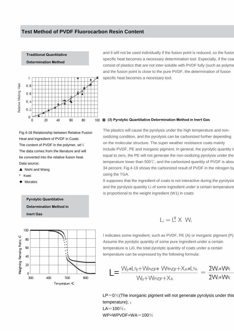
The plastics will cause the pyrolysis under the high temperature and non-
oxidizing condition, and the pyrolysis can be carbonized further depending
on the molecular structure. The super weather resistance coats mainly
include PVDF, PE and inorganic pigment. In general, the pyrolytic quantity is
equal to zero, the PE will not generate the non-oxidizing pyrolysis under the
temperature lower than 500℃, and the carbonized quantity of PVDF is about
34 percent. Fig.4-19 shows the carbonized result of PVDF in the nitrogen by
using the TGA.
It supposes that the ingredient of coats is not interactive during the pyrolysis
and the pyrolysis quantity Li of some ingredient under a certain temperature
is proportional to the weight ingredient (W1) in coats:
I indicates some ingredient, such as PVDF, PE (A) or inorganic pigment (P).
Assume the pyrolytic quantity of some pure ingredient under a certain
temperature is Li0, the total pyrolytic quantity of coats under a certain
temperature can be expressed by the following formula:
Test Method of PVDF Fluorocarbon Resin Content
(3) Pyrolytic Quantitative Determination Method in Inert Gas
LP=0%(The inorganic pigment will not generate pyrolysis under this
temperature); ;
LA=100%;
WP+WPVDF+WA=100%
Pyrolytic Quantitative
Determination Method in
Inert Gas
Fig.4-18 Relationship between Relative Fusion
Heat and Ingredient of PVDF in Coats
The content of PVDF in the polymer, wt%
The data comes from the literature and will
be converted into the relative fusion heat.
Data source:
▲ Nishi and Wang
* Kwei
◆ Morales

WP can be determined by the air pyrolysis. Certainly, the use of the organic
pigment will cause serious error. In general, the organic pigment is high cost
and not weather resistance. To reduce the cost and the content of PVDF in
coats, the use of the expensive organic pigment may not be rational. L is
determined by TGA, and then WPVDF can be obtained by the calculation.
To verify the reliability of this determination method, we get the coats with
different PVDF contents, where the content of the pigment (TiO2/Shepherd
Blue#3=1/1) is 33.3%. It will cause the pyrolysis in the inert gas under the
temperature 760℃. The pyrolytic quantity of PVDF itself under this
temperature is 66.6±1.8%. Fig.4-20 demonstrates this principle is
practicable. In this experiment, the PE and pure PVDF coats provide 32.1%
and 34.0% of the pigment content respectively by using the linear relation,
which are close to the expected value 33.3%. It demonstrates this
determination method can be used to carry out the quick quantitative
analysis of the PVDF content in coats reliably.
Test Method of PVDF Fluorocarbon Resin Content
Pyrolytic Quantitative
Determination Method in
Inert Gas
Fig.4-20 Reliability Determination of
Pyrolytic Quantitative Analysis Method
in Inert Gas
Conclusion(4) Conclusion
Above describes two micro-determination methods for the reference.
These two methods can be used together with each other. However,
the investment of instruments and the maintenance cost are high. In
face, DSC and TGA are used in the some institutes.

This method simulates the bending fatigue condition of slotting and bending
system for Aluminum Composite Panels under the continuous inward (positive
wind pressure) and outward (negative wind pressure) action of the wind load,
and it is applicable to evaluate the capacity of the folding life under the cyclic
deformation of Aluminum Composite Panels.
Test Method of Folding Life Test Method of Folding Life Test Method of Folding Life Test Method of Folding Life
under Cyclic Deformation under Cyclic Deformation under Cyclic Deformation under Cyclic Deformation
of Aluminum Composite of Aluminum Composite of Aluminum Composite of Aluminum Composite
PanelsPanelsPanelsPanels
Test Instruments and Equipments:
The folding life performance test machine under cyclic deformation consists
of frames, pneumatic actuation parts, fixture clamping parts and operation
control parts as shown in Fig.1. The instrument simulates the deformation of
Aluminum Composite Panels under the wind load by controlling the central
stress of Aluminum Composite Panels.
1.Determine the range of swing and the expansion/contraction frequency:
connect the control parts to the 220V power supply and determine the
swing by adjusting the position of magnetic switches according to the
requirement of test. Adjust the supply pressure and the displacement of
compressed air to determine the expansion/contraction frequency.
2.Sampling: Feed the material according to the dimension in the sampling
installation diagram (Fig.2), slot and manufacture rivet holes with the
diameter Ф5.2~Ф5.5. Bend the sample according to the test solution and
rivet it with the supporting part by the Ф5 rivet.
3.Fixture: Loose the positioning device of fixture parts, and place the
prepared sampling on instruments, and use the Φ5 rivet to fix samplings in
the sample bed. Drill holes with Ф6.5 in samplings by the gun drill
according to the hole on the clamp of fixture parts. Use M6 screws to fix
clamp plates, samplings and clamps.
4. Press the Reset button of control parts and clear the counter. Press the
Start button to start the test. When the length of crack at the right corner of
the sampling can meet the requirement, press the Stop button and record
the expansion/contraction times of samplings and then complete the test.
Test Method of Folding Life under Cyclic Deformatio n of Aluminum Composite Panels
B.1 General Regulation
Fig.B.2 Test Installation Diagram
Fig.B.1 Schematic Diagram of Angular
Strength Test Machine
4X Magnifier
Steel ruler with the accuracy 1mm
B.2 Determination Method
B0.3 Evaluation Method
If the cracking of any part for Aluminum Composite Panels at the slotting and bending point of Aluminum
Composite Panels is up to 50mm, the vibration times are the test times of the dynamic fatigue strength of
Aluminum Composite Panels.
Test Method of Folding Life
under Cyclic Deformation
of Aluminum Composite
Panels
Test Method of Folding Life under Cyclic Deformatio n of Aluminum Composite Panels

Test and Identification Methods of Combustion Properties for Fireproof
Aluminum Composite Panels and Common Aluminum Composite Panels
C.1 Scope
This specification specifies the exposure field, test bed, test sampling and test steps for the test method of the
natural environmental exposure for Aluminum Composite Panel coatings.
This specification is applicable to the open natural environmental exposure test, and used for evaluating the
weather resistance of coatings for the exposure under the outdoor natural condition.
Test Method of Natural
Environmental Exposure
for Aluminum Composite
Panels
C.2 References
The clauses in the following documents that were cited by this Standard became clauses of this Standard. For cited
documents with a date, all their subsequent modifications (excluding the errata content) or revisions do not apply to
this Standard. However, parties having reached an agreement based on cited standards are encouraged to study
whether the latest versions of the cited documents are applicable.
GB/T 1766-1995 Paint and Varnish -- Rating schemes of degradation of coats (ISO 4628-1: 1980 NEQ)
GB/T 9754 Paints and Varnishes -- Measurement of Specular Gloss of Non-metallic Paint Films at 20°, 60°and
85° (GB/T 9754-1988 ISO 2813: 1978 EQV)
GB/T 4957 (All parts) Non-conductive Coats on Non-magnetic Metal Substrates -- Measurement of Coats Thickness
-Eddy Current Method (GB/T 4957-2003 ISO 2360: 1982 EQV)
GB/T 11186.2-1989 Methods for Measuring Color of Paint Films - Part 2: Color Measurement (EQV ISO7724.2:
1984)
C.3 Definition
This standard adopts the following definitions:
C.3.1 Weather Resistance
The endurance of Aluminum Composite Panels under the action of natural weather factors
C.3.2 Natural Environmental Exposure
The test used to observe the change of performance for the test piece by placing Aluminum Composite
Panels into the natural environment to imple
Test Method of Folding Life under Cyclic Deformatio n of Aluminum Composite Panels

ment the integrated action of various weather factors
C.3.3 Open Exposure
The exposure method that places samples into the ventilated air and there is no cover on it or pad under it
C.4 Exposure Test Field
C.4.1 The exposure test field should be selected to establish at the most rigorous district that represents
various types of climates or under the actual use environment of products to be tested.
C.4.2 The exposure test field should be even, spacious, without accumulated water, and the height of grasses
should not exceed 0.3m.
C.4.3 There should not be the factory chimneys and facilities that can emit a large number of corrosive gases
around the exposure plant, to prevent from the effect of local serious pollution.
C.4.4 The exposure test field should be equipped with the meteorological observation instrument, which is
located around the national weather station to make use of much observation material of this station directly.
The meteorological data mainly includes the air temperature and humidity, sunshine duration, solar radiation,
rainfall, wind speed and wind direction.
Test Method of Natural
Environmental Exposure
for Aluminum Composite
Panels
C.5 Exposure Test Bed
C.5.1 The exposure test bed is the support used for the exposure test sample within the exposure field, which
should be made of the inert materials that don’t affect the test result, such as the wood, reinforced concrete,
aluminum alloy or the steel with the anticorrosive coats. The structure should be firm as soon as possible to
endure local maximal wind power.
C.5.2 Samples within the exposure test bed should be isolated from the metal and should not contact with the
wood or the porous material as much as possible. It is recommended to use the porcelain isolators to fix
samples.
C.5.3 The placement of the exposure test bed should ensure the free ventilation between test beds. In order
to prevent the sunshine shield and provide the convenience for work, the row spacing should not be less than
1m.
Test Method of Folding Life under Cyclic Deformatio n of Aluminum Composite Panels

Test and Identification Methods of Combustion Properties for Fireproof
Aluminum Composite Panels and Common Aluminum Composite PanelsTest Method of Folding Life under Cyclic Deformation of Aluminum
Composite Panels
Test Method of Natural
Environmental Exposure
for Aluminum Composite
Panels
C.6 Test Samples
The sample size for the natural weather exposure test is specified as 300mm×300mm. At the same time, it
will prepare three exposure samples and one standard sample for the contrast. The distance from the plate
edge for cutting should not be less than 50mm.The standard samples should be stored in the place that
provides excellent indoor ventilation, drying and without the lighting radiation.
Test Method of Natural
Environmental Exposure
for Aluminum Composite
Panels
C.7 Test Steps
C.7.1 You should observe the appearance of coating films for samples, such as the gloss, color and physical
and mechanical performance to be tested, and carry out the original record, mainly including the name of
manufacturers, original gloss, thickness of paint film coats, surface status of paint films as well as the test
date.
C.7.2 The result of the exposure test will vary depending on the test season. However, this effect will be
reduced with the increasing of the exposure time. In general, the exposure test season is specified at the end
of spring and at the beginning of summer.
C.7.3 Year and month are taken as the time unit of the exposure test. Unless special otherwise stated, it will
be checked once every month within 1 year of the use, and then it will be checked for once every three
months after 1 years. It can also take a certain sun radiation that the sample surface suffers from as the
exposure period. When the weather changes suddenly, it should be checked at any time. If any abnormity
takes place, it should be recorded or taken photo.
C.7.4 The exposure term of samples may comply with the requirement of product standards or put forward
the forecasted time (month and year), or
C.5.4 The distance from the bottom of the exposure test bed to the ground should not be less than 0.5m.
C.5.5 The exposure test bed is oriented to the equatorial and is 45º with the horizontal line to expose
samples. To make the surface of samples suffer from the maximal sun radiation, the exposure test bed
should be placed in local latitude angle with the horizontal line.
Test Method of Folding Life under Cyclic Deformatio n of Aluminum Composite Panels

take the sun radiation the samples suffer from as the exposure term, or specify the duration as the exposure
term when the exposure samples reach some aging damage degree.
C.7.5 The gloss and color of the exposure Aluminum Composite panel samples should be measured
according to GB/T 9754 and GB/T 11186.2, and the rating of degradation for paint film coats should be
carried out according to GB/T 9277.
Test Method of Natural
Environmental Exposure
for Aluminum Composite
Panels
Test Method of Folding Life under Cyclic Deformatio n of Aluminum Composite Panels
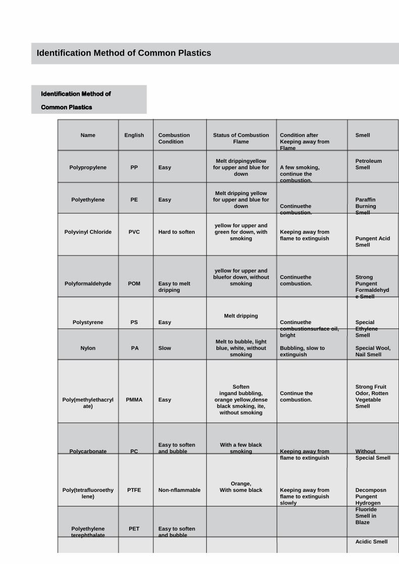
Identification Method of Common Plastics
Identification Method of Identification Method of Identification Method of Identification Method of
Common PlasticsCommon PlasticsCommon PlasticsCommon Plastics
Name
Polypropylene
Polyethylene
Polyvinyl Chloride
Polyformaldehyde
Polystyrene
Nylon
Poly(methylethacrylate)
Polycarbonate
Poly(tetrafluoroethylene)
Polyethylene terephthalate
English
PP
PE
PVC
POM
PS
PA
PMMA
PC
PTFE
PET
Combustion Condition
Easy
Easy
Hard to soften
Easy to melt dripping
Easy
Slow
Easy
Easy to soften and bubble
Non-nflammable
Easy to soften and bubble
Status of Combustion Flame
Melt drippingyellowfor upper and blue for
down
Melt dripping yellow for upper and blue for
down
yellow for upper and green for down, with
smoking
yellow for upper and bluefor down, without
smoking
Melt dripping
Melt to bubble, light blue, white, without
smoking
Softeningand bubbling,
orange yellow,denseblack smoking, ite, without smoking
With a few black smoking
Orange, With some black
Condition after Keeping away from Flame
A few smoking, continue the combustion.
Continuethecombustion.
Keeping away from flame to extinguish
Continuethecombustion.
Continuethecombustionsurface oil, bright
Bubbling, slow to extinguish
Continue the combustion.
Keeping away from flame to extinguish
Keeping away from flame to extinguish slowly
Smell
Petroleum Smell
Paraffin Burning Smell
Pungent Acid Smell
Strong Pungent Formaldehyde Smell
Special Ethylene Smell
Special Wool, Nail Smell
Strong Fruit Odor, Rotten Vegetable Smell
Without Special Smell
DecomposnPungent Hydrogen Fluoride Smell in Blaze
Acidic Smell

5005
Al-Mg Alloy
45
7
159
97
Antirust aluminum with excellent weather
resistance and anti-corrosive performance, the
back of Aluminum Composite Panels needs not to
carry out the paint baking process
Internal and external decoration
3003
Aluminum-manganese Alloy
47
6 - 14
175
105
More smooth panel and optimal rigidity
Be more applicable to the exhibition show, panel printing and screen printing
1000
Pure Aluminum
44
5
152
90
Smooth panel surface and light mass
Internal and external decoration, as well as advertisement
ItemSeriesAlloy Components
Surface Hardness, HB
Extension and Manufacturing Characteristics (%)
Bending Strength (MPa)
Shearing Strength (MPa)
Advantages
Key Scope of Application
Aluminum Alloy
1100 Aluminum Alloy
3003 Aluminum Alloy
5005 Aluminum Alloy
Contrast
Thickness of Aluminum
50
50
50
Total Thickness
4
4
4
Coats
PVDF2
PVDF3
Double Faced
PET
Bending Strength (MPa)
127.91
161.11
133.59
Fig.1
Bending Elastic Modulus (MPa)
30666.97
33550.41
31387.73
Fig.2
Perforation Resistance (KN)
8.38
9.69
8.71
Fig.3
Shearing Strength(MPa)
26.01
30.29
27.75
Fig.4
Contrast Table of Different Aluminum Series
Contrast Table of Different Aluminum Series
Effect of Different Aluminum Alloys on Mechanical Properties of Aluminum Composite Panels
Characteristics:
The 1100 Aluminum Alloy can provide products stably, the 3003 Aluminum Alloy can provide high hardness
and excellent anti-deformation capacity, and the 5005 Aluminum Alloy can provide high toughness and
excellent bending performance.
Classification of Use:
The 3003 (or 3105) Aluminum Alloy is taken as the advertisement panel and can provide excellent surface
smoothness and anti-deformation performance. The 5005 Aluminum Alloy is taken as the high-level buildings,
and the folding edge will improve its service life greatly.
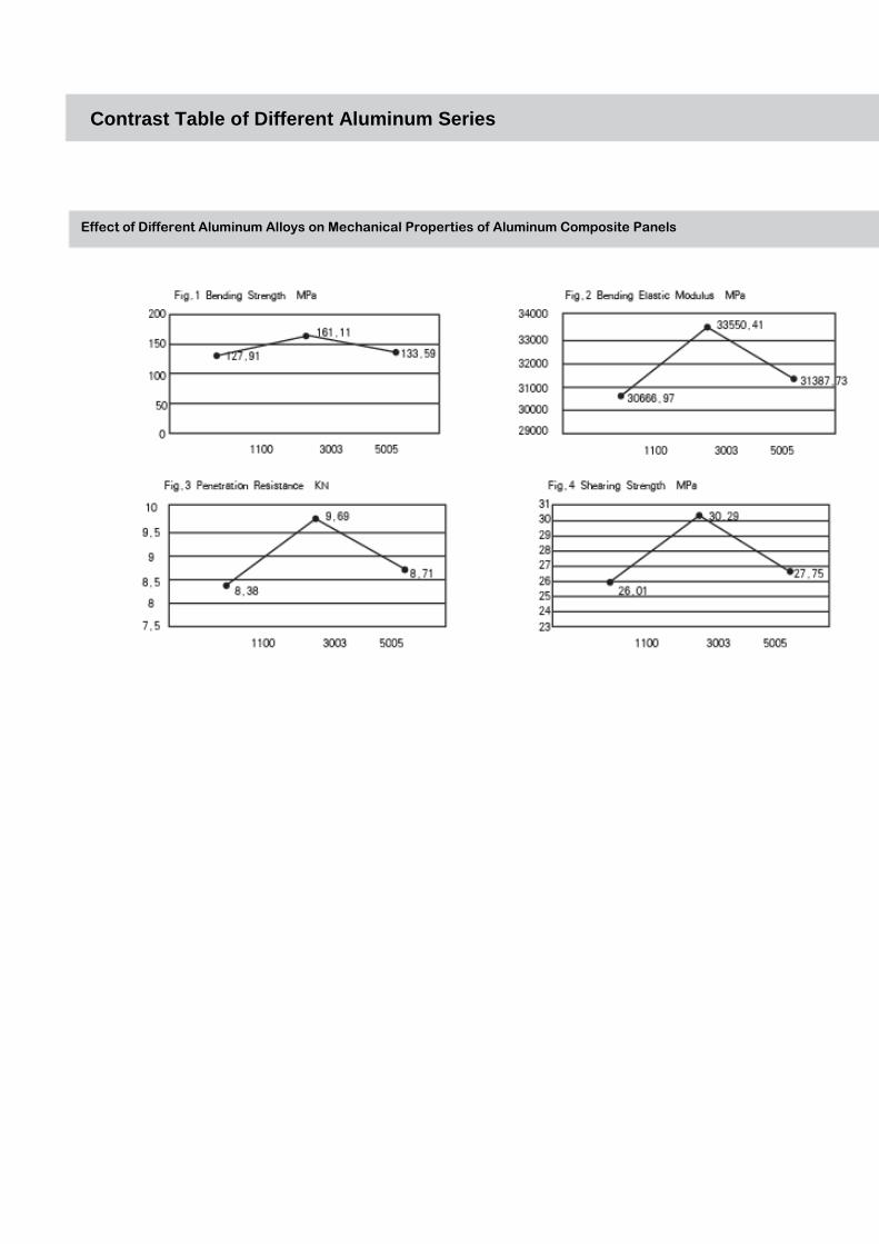
Contrast Table of Different Aluminum Series
Effect of Different Aluminum Alloys on Mechanical Properties of Aluminum Composite Panels

Item Classification
Main Components
Environmental ProtectionPerformance
Specific Gravity (㎏/㎡(4mm))
Advantages
Key Scope of Application
LDPE
High Pressure and Low Density PE
Recyclable and in-noxious
5.7
Easy to bend and deform, excellent toughness and
multiple forms
Indoor and outdoor decoration, advertisement ID and curtain
wall application
PP
Polypropylene
Recyclable and in-noxious
5.4
High hardness, a new composite material, the weight is reduced by 60 percent than that of
the steel plate. The weight is reduced by about 30 percent. Furthermore, it can provide
excellent ratio of mass to rigidity.
Plane advertisement, printing, screen printing, internal and external decoration and isolation plate of container, steamboat, automobile and
train
Flame Retardant Core Material
Magnesium Hydroxide Flame Retardants
Recyclable and in-noxious
6.7
Fireproof and flame retardant
For the site with high requirement for the fireproof performance, the fireproof level can be
up to level A or level B according to the difference of requirements.v
Thickness of Aluminum
30
30
Plastics
PEPlastics
PP Plastics
Contrast
Total Thickness
2
2
Perforation Resistance (KN)
4.71
5.51
Fig.3
Coats
Double-sidePET
Double-sidePET
Bending Strength (MPa)
95.54
107.48
Fig.1
Bending Elastic Modulus (MPa)
24643.84
26922.42
Fig.2
Shearing Strength (MPa)
27.21
31.83
Fig.4
Characteristics:The PE product is mature.PP can provide high hardness and excellent anti-deformation capacity.Classification of Use:The advertisement board can use PP.
Performance Contrast Table of Different Core Materi als
Performance Contrast Table of Different Core Materials
Effect of Different Plastic Core Panels on Mechanical Properties of Aluminum Composite Panels

Effect of Different Plastic Core Panels on Mechanical Properties of Aluminum Composite
Panels
Performance Contrast Table of Different Core Materi als

Manufacturing Method of Aluminum Composite Panels
Manufacturing Method of Aluminum Composite Panels
Aluminum Composite Panels are simple to manufacture and convenient to fabricate. Furthermore, it can carry out several manufacturing operations as follows:
1 Trimming:
Trimming: The trimming of Aluminum Composite Panels must be
carried out on the trimming equipment designed for the metal plate. It
should ensure the flatness of Aluminum Composite Panels during the
manufacturing, and there should not be the impurity and foreign
matter on the platform of trimming machines. It should ensure the
cleanliness for the platform of trimming machines. During the
trimming, refer to the table below for reserved appropriate machining
allowance and the front angle of inclination for the trimming machine.
3mm Aluminum Composite Panels
Panel MaterialsSpecification of Aluminum Composite
AllowanceMachining
4mm Aluminum Composite Panels
4mm Aluminum Composite Panels
0.04 mm
0.04 mm
0.2mm
1°
1°302
1°302
for trimming Machine
Test Tools and Methods: Visual inspection by steel ruler.
Sawing: The sawing of Aluminum Composite Panels must be carried
out on the sawing equipment designed for the metal plate. It should
ensure the flatness of Aluminum Composite Panels during the
manufacturing. It should use the plate to fix and manufacture in the
cutting saw movement way during the sawing, to ensure the flatness
of the manufacturing edge and the linearity of the manufacturing plate.
The blade of the sawing machine is dedicated manufacturing saw for
the metal plate. The rotation speed of the machining equipment
should not be less than 3000 rpm, and the machining movement
speed should not be greater than 5m/min.The movement of the saw
must feed against the linear rolling guide, and the saw should move
smoothly. After the cutting of Aluminum Composite Panels, there
should not be the burr and foreign matter of the plate sandwich for the
machining edge.
44
2 Slotting:
The molding process of the curtain wall for Aluminum Composite
Panels doesn't allow machine the folding edge directly. It should carry
out the slotting and prepare for the folding edge before the bending.
The slotting depth must be controlled for 0.3mm of plastic core
material after the frontal Aluminum Composite Panel, to ensure
enough toughness of Aluminum Composite Panels and prevent the
aluminum fracture at the folding edge.
The slotting of Aluminum Composite Panels must be carried out on
the dedicated machine equipment. It should use flat base plates at the
back of Aluminum Composite Panels during the manufacturing, to
ensure the flatness of Aluminum Composite Panels for the slotting
process. It should use plates to fix and manufacture in the slotting saw
movement way during the slotting, to ensure the slotting size and the
linearity of the manufacturing slots. The saws of machining
equipments are dedicated slotting saw for the metal plate. The rotation
speed of the machining equipment should not be less than 3000 rpm,
and the machining movement speed should not be greater than
5m/min.The movement of saws must feed against the linear rolling
guide and the saw should move smoothly.
3 Bending
It should use the tool with handles to bend the folding edge for one
time during the bending. It should not be bent or deformed for several
times. The contact placement between the bending tools and
Aluminum Composite Panels should be equipped with the soft
material (felt, plastics and rubber pad). It should make the force
distributed evenly during the bending, to prevent the deformation of
Aluminum Composite Panels.
During the second bending, the pad should be placed on Aluminum
Composite Panels (Material requirement: wood block and hard plastic
block). The platform should be placed at the bottom of the concave
right edge folding (there is no impurity for the platform). It is required
to place the pad at the folding edge during the second folding edge.
45
Manufacturing Method of Aluminum Composite Panels
Manufacturing Method of Aluminum Composite Panels
4 Rolling
Vertical and parallel rolling refers to the relationship between the
bending direction and the extension texture of Aluminum Composite
Panels. The bending radius of Aluminum Composite Panels without
the surface process refers to the minimal bending radius under the
condition that the surface of Aluminum Composite Panels doesn't
show obvious wrinkle. The bending radius of Aluminum Composite
Panels for the coats is the minimal bending radius. However, not any
abnormity such as the crack and broken mark can almost be detected
at the bending point.
For the rolling process, the bending angle depends on the diameter
and space of the axis. It will always show the flat part of the start point
and end point during the bending (the flat part should be 5 times of the
thickness for Aluminum Composite Panels at least). If it is required
that there is no the flat part for the project design, it should cut the flat
part before the bending process.
For the rolling process, the rubber pad or the material with the
hardness lower than Aluminum Composite Panels should be placed at
the mould mouth, to prevent the extension of Aluminum Composite
Panels. The surface of the bending equipment axis should be clean
and there should not be the dent or impurity, to prevent the concave
and convexity of Aluminum Composite Panels and twisting of
Aluminum Composite Panels surface during the bending process.
46
5 Drilling
The drilling of Aluminum Composite Panels complies with the
mechanic drilling process. It doesn't allow the drilling process of
Aluminum Composite Panels on the non-mechanic equipments.
6 Punching
The punching of Aluminum Composite Panels complies with the
mechanic punching process. It doesn't allow the punching process of
Aluminum Composite Panels on the non-mechanic equipments.
Manufacturing Method of Aluminum Composite Panels
Manufacturing Method of Aluminum Composite Panels

The punching shear loss will take place on Aluminum Composite
Panels during the punching, so the size of holes (in general, the
diameter should be greater than 4mm) should not be too large,
otherwise, it will cause the deformation of the hole edge.
The allowance of holes for the punching should be as small as
possible, and it is usually applicable to be 5 percent of the thickness
for Aluminum Composite Panels (This data is only for the reference).
The punch should not use the direct column one. It is suggested to
use the trapezoidal punch to carry out the separate punching shear
during the punching.
7 Other process types, such as the surface treatment, including the
screen printing and plane printing.
47
Manufacturing Method of Aluminum Composite Panels
Manufacturing Method of Aluminum Composite Panels

Fabrication Method of Aluminum Composite Panels
Fabrication Method of Aluminum Composite Panels
1. The specification and color of Aluminum Composite Panels should
meet the requirement of the project design.
2. The manufacturing allowance of Aluminum Composite Panels
should comply with the regulation in Table 1.
48
3. Deep Processing of Aluminum Composite Panels:
The attention should be paid to the surrounding environment and the
metal scraping from the cutting should be cleaned in time, to prevent
from scratching the surface of Aluminum Composite Panels during the
processing. The manufacturing and storage of Aluminum Composite
Panels should not be carried out in the damp environment, and there
should not be water accumulation around the manufacturing field. It is
strictly prohibited to cause the water accumulation on Aluminum
Composite Panels. If Aluminum Composite Panels are in the rain
during the transportation and shipment, they should not be placed
together immediately, but be placed only after Aluminum Composite
Panels are dried completely.
a、Cutting: Aluminum Composite Panels can use the circular saw
cutting, wire saw cutting and punching shear cutting.
Table 1 Manufacturing Allowance of Aluminum Composite Panels (MM)
Test
Edge Length
Allowance Test Tools
2000
>2000
±2.0
±2.5
Steel Tape and Steel Ruler
Steel Tape and Steel Ruler
2000
>2000
2.5
3.0
Steel Tape and Steel Ruler
Steel Tape and Steel Ruler
Opposite-side Size
Diagonal Length2000
>2000
2.5
3.0
Steel Tape and Steel Ruler
Steel Tape and Steel Ruler
Bending Height 1.0 Steel Tape and Steel Ruler
Center Space of Holes ±1.5 Steel Tape and Steel Ruler
Flatness 2/1000 Steel Tape and Flat Ruler
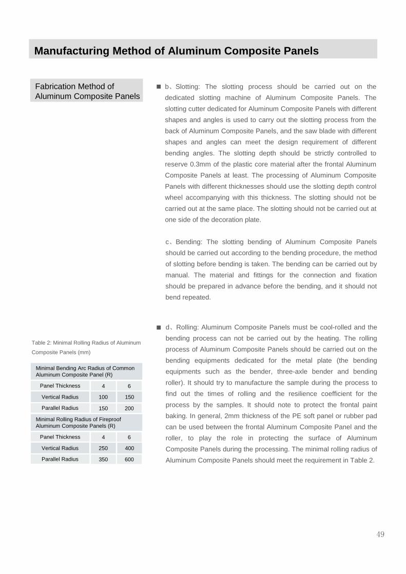
b、Slotting: The slotting process should be carried out on the
dedicated slotting machine of Aluminum Composite Panels. The
slotting cutter dedicated for Aluminum Composite Panels with different
shapes and angles is used to carry out the slotting process from the
back of Aluminum Composite Panels, and the saw blade with different
shapes and angles can meet the design requirement of different
bending angles. The slotting depth should be strictly controlled to
reserve 0.3mm of the plastic core material after the frontal Aluminum
Composite Panels at least. The processing of Aluminum Composite
Panels with different thicknesses should use the slotting depth control
wheel accompanying with this thickness. The slotting should not be
carried out at the same place. The slotting should not be carried out at
one side of the decoration plate.
c、Bending: The slotting bending of Aluminum Composite Panels
should be carried out according to the bending procedure, the method
of slotting before bending is taken. The bending can be carried out by
manual. The material and fittings for the connection and fixation
should be prepared in advance before the bending, and it should not
bend repeated.
Manufacturing Method of Aluminum Composite Panels
Fabrication Method of Aluminum Composite Panels
49
d、Rolling: Aluminum Composite Panels must be cool-rolled and the
bending process can not be carried out by the heating. The rolling
process of Aluminum Composite Panels should be carried out on the
bending equipments dedicated for the metal plate (the bending
equipments such as the bender, three-axle bender and bending
roller). It should try to manufacture the sample during the process to
find out the times of rolling and the resilience coefficient for the
process by the samples. It should note to protect the frontal paint
baking. In general, 2mm thickness of the PE soft panel or rubber pad
can be used between the frontal Aluminum Composite Panel and the
roller, to play the role in protecting the surface of Aluminum
Composite Panels during the processing. The minimal rolling radius of
Aluminum Composite Panels should meet the requirement in Table 2.
Panel Thickness
Minimal Bending Arc Radius of Common Aluminum Composite Panel (R)
4 6
Parallel Radius 150 200
Vertical Radius 100 150
Panel Thickness
Minimal Rolling Radius of Fireproof Aluminum Composite Panels (R)
4 6
Parallel Radius 350 600
Vertical Radius 250 400
Table 2: Minimal Rolling Radius of Aluminum
Composite Panels (mm)

e、Drilling: The drilling of Aluminum Composite Panels can be carried
out on common metal processing equipments by common twist drill,
and the three-side incline core drill and the flat-bottom reaming drill
can be used to carry out the conical port enlarging process on
Aluminum Composite Panels. The distance from the center of holes to
the edge of the center-to-center distance should not be less than 2
times of the aperture, and the center-to-center distance of holes
should not be less than 3 times of the aperture. During the drilling,
there should not be the impurity and uneven surface of the drilling
platform, to prevent the concave and convex of Aluminum Composite
Panels and twisting Aluminum Composite Panels surface.
50
g、Corner Combining: The combining of Aluminum Composite Panels
into the box shape should cut four corners before the folding. The
seam at the corner during the folding should be tight and smooth, and
it should be punched by using dedicated punching machines. During
the corner combining, the Aluminum Composite Panels with the
thickness not less than 1.5mm should be placed by at the back of the
seam, and the rivets should be used to connect Aluminum Composite
Panels with the lining plate.
4. Assembly of Curtain Wall for Aluminum Composite Panels:
The assembly of Aluminum Composite Panels refers to fabricate into
the box-shaped plate after the slotting. The assembly technique
includes the folding, corner combining and the connection with the
reinforced
f、Punching: The common plate severing machine can be used to
carry out the punching process, the punching diameter should be
greater than 4mm, and the distance from the center of holes to the
edge of the panel should not be less than 2 times of the aperture, and
the center-to-center distance of holes should not be less than 3 times
of the aperture. There should not be the impurity and uneven surface
of the drilling platform, to prevent the concave and convex of
Aluminum Composite Panels and twisting Aluminum Composite
Panels surface.
Fabrication Method of Aluminum Composite Panels
Fabrication Method of Aluminum Composite Panels

aluminum material at the edge. For the curtain wall application, the
connection will use the bulbed rivet. Some design uses the structural
two-sided tape to assist in connecting the reinforced aluminum
material and the aluminum plate at the back.
b、Bolt Connections:
-- Aluminum Composite Panels should be connected by the stainless
steel bole with the sealed washer.
-- During the connection, it should reserve a 0.3mm of seam between
the hole and the bolt, to prevent Aluminum Composite Panels from the
deformation by the extrusion.
-- The washer and nut should not extrude the protection film of
Aluminum Composite Panels. It should remove the protection film
around the rivet.
[Description] The hot air can be used to weld plastics or connect
Aluminum Composite Panels. It is not recommended to use the hot air
method to connect during the fabrication of curtain walls for Aluminum
Composite Panels.
51
a、Rivet Connection:
The curtain wall of Aluminum Composite Panels should use the
bulbed rivet with the stainless steel core material, and the countersunk
rivet should not be used to the curtain wall.
-- For the rivet connection, it should reserve the seam no more than
0.3mm between the hole and the rivet, to prevent Aluminum
Composite Panels from the deformation by the extrusion.
-- The rivet should not extrude the protection film of Aluminum
Composite Panels. It should remove the protection film around the
rivet.
-- Use the rivet connection to prevent the electric corrosion for the
metal with different materials, and a layer of insulated material pad
should be placed at the connection point of different metal layers.
5. Fabrication of Reinforced Rib for Curtain Wall of Aluminum
Composite Panels
a、Assembly of Reinforced Rib: The structural assembly method
should be used to reinforce the back of Aluminum Composite Panels.
Both sides of the reinforced rib should be connected with the
reinforced material at the edge of panels effectively.
Fabrication Method of Aluminum Composite Panels
Fabrication Method of Aluminum Composite Panels

b、The materials and coats of the reinforced rib should be compatible
with the structural adhesive or tape.
52
c、The assembly method should meet the requirement of the
construction specification for the structural adhesive when the
reinforced rib and the back of Aluminum Composite Panels use the
structural adhesive to carry out the structure assembly.
d、For the component after the structure assembly and connection,
there should not be degumming and separation between the back of
Aluminum Composite Panels and the reinforce rib.
e、If the structural bonding tape is used, it should apply enough
pressure and maintain the time up to the bonding force between the
bonded parts.
[Description] If the size of panel is large, it should be reinforced in the
structural assembly way at the back of Aluminum Composite Panels
according to the design wind load value of the project. The reinforced
material should use the aluminum alloy (may be U-shape, C-shape or
square tube). The reinforced rib and the back of Aluminum Composite
Panels should use the structural adhesive or tape to connect
effectively. It is required that the structural adhesive or structural tape
be compatible with the reinforced rib and the back of Aluminum
Composite Panels (or the surface of naked aluminums after the
chemical processing).
6. The fittings and connector of curtain walls for Aluminum Composite
Panels should comply with the following regulation:
a、The hanging and supporting parts used for curtain walls of the unit
Aluminum Composite Panel should use the aluminum alloy or
stainless steel and provide the adjustable range.
b、The connection between the hanging parts and the embedded
parts of the unit curtain wall should use the penetration bolt.
c、When the screw connection is used between the panel and the
skeleton or among the skeletons, the local wall thickness of the
aluminum material connection parts should not be less than nominal
diameter of screws.
[Description]
3 If the thickness of the aluminum material is less than the nominal
diameter of screws, it can be reinforced at the connection part locally.
Fabrication Method of Aluminum Composite Panels
Fabrication Method of Aluminum Composite Panels

Construction and Installation of Curtain Walls for Aluminum Composite Panels
Construction and Installation of Curtain Walls for Aluminum Composite Panels
1. The installation of the fitting steel and the aluminum angle ruler
should be determined by calculating the load and action for Aluminum
Composite Panels under the most unfavorable working condition.
2. The installation of curtain wall columns for Aluminum Composite
Panels should comply with the following regulation:
1 The allowance of the column installation axis is ±2mm.
2 The allowance of the installation elevation for two adjacent
columns is ±3mm, the allowance of the maximal elevation for the
same layer of columns is ±5mm, and the allowance of the distance
between two adjacent columns is ±2mm.
3 The column should be fixed in time after it is installed in place and
adjusted.
[Description] The installation accuracy and quality of curtain walls
column for Aluminum Composite Panels will have an effect on the
installation quality of the whole curtain wall, and is a critical factor of
the installation and construction of curtain walls. Hence, this regulation
should control the difference between the axis of curtain walls plane
and the outer plane axis by the 3D adjustment of the connection parts.
Especially for curtain walls whose building plane is the arc, round and
surrounding closure, special care should be taken to the installation
and construction for the distance between the internal and external
axis has an effect on the perimeter of curtain walls and the closure of
the metal and stone plate.
The length of the column is usually determined according to the
building requirement, force condition, construction and transportation
condition. In general, one floor height of the building is a whole column
and there should be some slot greater than 15mm. The core column
connection method can be used between the columns, to
accommodate to and eliminate the effect of the deformation of the
building for the force and temperature difference.
3. The installation of curtain walls beam for Aluminum Composite
Panels should comply with the following regulation:
1 The beam should be installed fixed and the seam should be tight.
If there is the extension/contraction seam between the beam and the
column, the design requirement should be met. When the sealed
53
Construction and Installation of Curtain Walls for Aluminum Composite Panels
Construction and Installation of Curtain Walls for Aluminum Composite Panels
adhesive seam is used, the construction of the adhesive seam should
be even, tight and continuous.
2 The allowance of both ends for the same beam or the horizontal
elevation of two adjacent beams is ±1mm. For the allowance of the
elevation for the same layer of beam, when the width of one curtain
wall is not greater than 35m, it can get 5mm, and when the width of
one curtain wall is greater than 35m, it can get 7mm.
3 After one layer of the height is installed completely, the check,
correction and fixation should be carried out in time.
[Description] In general, for the connection between the beam section
and column, enough gap should be reserved between two beams, or
the elastic rubber pad with enough compressed deformation capacity
(no lower than 20 – 35% usually) is used, to accommodate the
possible deformation of the structure or the extension/contraction
deformation caused by the temperature change of the beam. In
general, the bolt connection can be used between both ends of the
aluminum beam and the column, or the connection method of the
beam extension deformation may be used at one end. The welding
connection can be used between the steel beam and the column.
4. The installation of other main attachments for curtain walls should
comply with the following requirements.
1 The fireproof and insulation material should be placed smoothly
and fixed reliably, and there should not be seam at the connection
point.
2 The condensation water outlet pipe and its attachments should be
connected with the reserved hole of the horizontal elements tightly,
and the connection point with the drainage hole of the internal liner
panel should take the sealing measure.
3 Other ventilation slot, hole and rain outlet port should be
constructed according to the design requirement and should not be
neglected.
4 The sealing process should be taken at the sealing point.
5 The temporary bolts used for the installation and construction
should be removed in time after curtain walls is fixed.
[Description] The fireproof and insulation material should be placed
smoothly and fixed reliably, and there should not be seam at the
connec
54
Construction and Installation of Curtain Walls for Aluminum Composite Panels
Construction and Installation of Curtain Walls for Aluminum Composite Panels
tion point, and the design requirement should be met. If the
condensation water outlet pipe and its attachments are not connected
with the reserved hole of the horizontal elements tightly, or the
connection point with the drainage hole of the internal liner panel
doesn’t take the sealing measure, the condensation water may enter
into the internal curtain wall and cause the internal immersion and
corrosion, and have an effect on the performance and service life of
curtain walls.
5. The installation of curtain walls for Aluminum Composite Panels
should comply with the following regulation:
a Should check, measure and adjust the horizontal and vertical
connection parts, and reduce the installation error of Aluminum
Composite Panels.
b The installation of curtain walls for Aluminum Composite Panels
should be in the same direction as noted in the protection film.
c The seam between the panels should be 8mm at least.
d When Aluminum Composite Panels are riveted, it is suggested to
be fixed in the sequence from the middle to both ends of the panel.
Taking the extension/contraction of Aluminum Composite Panels
caused by the temperature change into account, the aperture on
Aluminum Composite Panels should be 1mm greater than the
diameter of rivets, to ensure the flatness of Aluminum Composite
Panels.
e For the rivet which carries out the structural fixation outdoors, the
diameter of stems should be 5mm and the diameter of rivet headers
should be 11mm~14mm.
f When the curtain wall seam of Aluminum Composite Panels is filled
with the silicone sealant for buildings (wet-process sealing hidden
panel seam), the width and thickness of Aluminum Composite Panels
should comply with the technical parameters of the silicone weather-
resistant sealant and meet the requirement of the calculated result.
g The shell nosing of curtain walls should take reliable waterproof
sealing measure.
h The protection film on the panel surface should be removed within
the date noted in the protection film.
55
Construction and Installation of Curtain Walls for Aluminum Composite Panels
[Description]
1 This clause specifies related regulation on curtain walls installation
of Aluminum Composite Panels:
2 For the coating process of Aluminum Composite Panels is the roll
coating, there are some difference of the color in the horizontal and
vertical direction, and it is specially obvious for the coats with the
metal color. Hence, to ensure the color consistence of curtain walls for
Aluminum Composite Panels, the same installation direction should
be ensured.
3 Enough deformation seams between the panels should be reserved,
to prevent the extrusion caused by the deformation of the main body
structure.
4 The edge of curtain walls should use Aluminum Composite Panels
or aluminum material to seal or take the waterproof and sealing
measure.
5 The protection film should be removed in time after the construction
is completed, to reduce the possibility that it is hard to remove, miss
the sealing adhesive or cause serious surface pollution of Aluminum
Composite Panels by the degradation of the protection film.
6 The Aluminum Composite Panels block should be installed
according to the design requirement and fixed after the adjustment is
completed.
7 The installation allowance of curtain walls for Aluminum Composite
Panels should comply with the regulation in Table 1 and 2.
56
Construction and Installation of Curtain Walls for Aluminum Composite Panels

Construction and Installation of Curtain Walls for Aluminum Composite Panels
Table 1: Assembly Allowance of Vertical and Horizontal Panel Material for
Curtain Walls of Aluminum Composite Panels (mm)
Spacing Size between Two Adjacent Vertical Panel Materials (Fixed End)
Item Size Scope Allowance Test Method
--
--
±2.0
±1.5
Steel Tape
measure tapeSteel
Steel Tape
Composite PanelTwo Adjacent Aluminum
Spacing Size between Two Adjacent Horizontal Panel
Materials
Difference of Division Diagonal
Horizontal Elevation Difference of Two Adjacent Horizontal Panel Materials
Horizontal Degree of Horizontal Panel Material
MaterialLinearity of Vertical Panel
If the spacing is less than or equal to 2000,
If the spacing is greater than 2000,
If the diagonal length is less than or equal
to 2000,
If the diagonal length is greater than 2000,
----
f the length of the component is less
than or equal to 2000,
If the length of the component is greater
than 2000,
----
±1.5
±2.0
≤3.0
≤3.5
≤2
≤2
≤3
2.5
Steel Tape or Extension/Cont
raction Ruler
Steel Tape or Gradienter
Gradienter or Level Ruler
2.0m Steel tape measureand Steel Tapev
Item Allowance Test Method
Vertical Seam and Vertical Degree of
Curtain Walls
Height of Curtain
Walls (H)
H≤30m
30m<H≤60m
60m<H≤90m
H>90m
≤10mm
≤15mm
≤20mm
≤25mm
Laser Theodolite or Theodolite
Flatness of Curtain Walls
Linearity of Vertical Seam
Linearity of Horizontal Seam
Width of Seam (Compare with the design value)
Difference of Seams between Two Adjacent Panels
≤2.5mm/2m
≤2.5mm/2m
≤2.5mm/2m
±2.0mm
≤1.0mm
2m Steel tape measure and Steel
Tape
2m Steel tape measure and Steel
Tape
Tapeand Steel measuretape 2m
Steel
Depth Indicator
Callipers
Table 2: Allowance of Curtain Walls Installation
57
Construction and Installation of Curtain Walls for Aluminum Composite Panels

Construction and Installation of Curtain Walls for Aluminum Composite Panels
8. In curtain walls of Aluminum Composite Panels, the silicone sealant
for buildings should not be constructed in rain. The sealant injected
temperature should comply with the product and design requirement.
Furthermore, the sealant injected surface should be cleaned and dried
before the sealant is injected.
[Description] The construction of the silicone sealant for buildings
should strictly comply with the construction process. The sealant
should not be injected if the lighting is not enough at night or the seam
is damp for rain. If it is necessary to construct for various reasons,
necessary protection measure should be taken, and the sealant
injected temperature should comply with the design requirement and
the product requirement, and should be within the specified
temperature range of products. Furthermore, the sealant injected
surface should be cleaned and dried before the sealant is injected.
The construction thickness of the silicone sealant for buildings
between the frame supporting curtain wall panel materials should be
usually controlled within 3.5mm~4.5mm. If the material is too thin, the
sealing quality can not be ensured and the rain leakage can not be
prevented. At the same time, it is disadvantage of the deformation
caused by the hot-swelling and cold-shrinkage of the aluminum alloy
frame. When it suffers from the tensile stress, it is easy to be broken
or damaged and lose the sealing and anti-leakage function if the
sealant seam is too large. The construction thickness of the silicone
sealant for buildings should not be less than two times of the thickness
or should be determined according to the actual calculated thickness.
The construction thickness and width of the sealant for the narrow
seam stone material curtain walls should comply with the design
requirement, the deep sealant seam bottom should be filled by the PE
foamed material, to ensure the design and construction position of the
silicone sealant for buildings.
The silicone sealant for buildings should be pasted at two opposite
sides within the seam and should not be pasted at three sides.
Otherwise, the sealant is easy to be torn down and will lose the
sealing and anti-leakage function when it is pulled and pushed. To
prevent the three sides paste, the tape without the paste can be
placed at the bottom of the sealant seam (at the bottom of the seam)
to separate the seam bottom and the sealant before the construction
of the silicone sealant for buildings.
58
Construction and Installation of Curtain Walls for Aluminum Composite Panels

Design of Curtain Wall Panel for Aluminum Composite Panels
General Requirement
1. The design of curtain walls panel for Aluminum Composite Panels
should use the surrounding folding method. Furthermore, it should not
contact with the surface layer Aluminum Composite Panel during the
slotting. The thickness of the remaining plastic core material should
not be less than 0.3mm after the slotting. The core material of
Aluminum Composite Panels should not expose to the atmosphere
directly. Aluminum Composite Panels without folding should use the
aluminum material inlay to fix around it or use the weather-resistant
sealants to seal.
[Description] Aluminum Composite Panels usually increases its rigidity
by the surrounding folding, and can prevent the core material of
Aluminum Composite Panels to expose the atmosphere. At present,
some projects also use Aluminum Composite Panels without folding
and adding of aluminum material method. At this time, Aluminum
Composite Panels should be embedded into the aluminum frame or
use the sealant to seal the core material. It should be noted to take
some measure to prevent the panel core from exposing the
atmosphere directly when it adopts the open curtain walls.
2. The folding of Aluminum Composite Panels can set the reinforced
frame and mid rib according to the requirement. Curtain walls panel of
Aluminum Composite Panels for the high-level building should not
take the aluminum angle ruler as the frame. The aluminum material
should be taken as the reinforced frame and middle rib. The reinforced
frame or rib can take the metal square tube, slot-shape or angle-
shape material. The reinforced frame or rib should be connected with
the panel reliably and should take the anti-corrosive measure. The
connection between the frame and the folding of Aluminum Composite
Panels can use the aluminum rivet, both ends of the middle rib should
be connected with the frame reliably, and its connection should meet
the requirement of the load transfer to connect reliably.
[Description] The folding of Aluminum Composite Panels can not be
taken as the frame of curtain walls panel for Aluminum Composite
Panels, and the frame and middle rib should be set according to the
requirement. For the intensity of the wind load that the high-level
building suffered is large, it is detected that the aluminum angle ruler
will be damaged before the panel of Aluminum Composite Panels is
I. General Requirement
59

General Requirement damaged if the amplitude is large during the folding life test under the
cyclic deformation of Aluminum Composite Panels. Hence, curtain
walls panel of Aluminum Composite Panels for the high-level building
should not take the aluminum angle ruler as the frame, but select the
aluminum material.
3. In addition to test curtain walls of Aluminum Composite Panels
according to the specified physical performance test items, the folding
life test under the cyclic deformation should be carried out for the
panel of the super high-level building and important project, to verify
the reliability of the panel design.
[Description] The folding life test under the cyclic deformation for
Aluminum Composite Panels is to simulate the action of the wind load,
fix Aluminum Composite Panels in the aluminum frame keel, and
make it generate inward (positive wind pressure action) and outward
(negative wind pressure action) bending continuously, and then test
the times of the final damages.
The connection method of Aluminum Composite Panels in curtain
walls is mainly divided into two types, the one is continuous folding
method, and the other is the slotted folding method. At present, the
most broadly used one is the slotted folding method. Aluminum
Composite Panels must remain 0.3mm of the core layer and 0.5mm of
Aluminum Composite Panel after the slotting. In this way, the self
weight of Aluminum Composite Panels and the positive and negative
wind load pressure of curtain walls will be undertaken by four 0.3mm
core layers and 0.5mm Aluminum Composite Panels. Hence, it is the
most weakened part of curtain wall panels for Aluminum Composite
Panels and the first damaged part under the wind load at the slotted
folding. Hence, understanding the folding life of Aluminum Composite
Panels under the cyclic deformation can evaluate the service life of
curtain wall panels for Aluminum Composite Panels according to local
meteorological information, and provide effective reference foundation
for the application of Aluminum Composite Panels in the high-level
curtain walls.
60
Design of Curtain Wall Panel for Aluminum Composite Panels
General Requirement II. Curtain Wall Panel Design
1. Curtain walls panel division formed in the reinforced frame can be
considered as the simply-supported edge along the surrounding edge
of curtain walls panel material, and the supporting line of the middle
rib can be considered as the fixed edge.
2. The maximal bending stress standard value under the wind load or
earthquake that is vertical to curtain wall panels of Aluminum
Composite Panels can be calculated by the geometric non-linear finite
element method or by the following formulas:
Where,σwk and σEk are the maximal bending stress standard
values generated under the wind load or the earthquake action in the
vertical direction
3. Under appropriate condition, the setting of the reinforced rib for
curtain walls panel can be designed by referring to the method in this
specification.
[Description] The anti-wind pressure design for curtain walls of
Aluminum Composite Panels is one of the critical factors that affect
the use of Aluminum Composite Panels on
Wk is the standard value of the wind load (N/mm2);
qEK is the standard value of the earthquake action in the direction
vertical to
curtain wall panels(N/mm2) ;
lx is the calculated side length of the panel division(mm),
m is the moment coefficient of curtain wall panels.
E is the elastic modulus of curtain wall panels(N/mm2) ;
t is the thickness of curtain wall panels (mm);
Weis the equivalent section modulus of Aluminum Composite Panels
(mm3/mm) ;
De is the equivalent bending rigidity of Aluminum Composite
Panels(Nmm2/mm) ;
is the reduced coefficient.
61
Design of Curtain Wall Panel for Aluminum Composite Panels
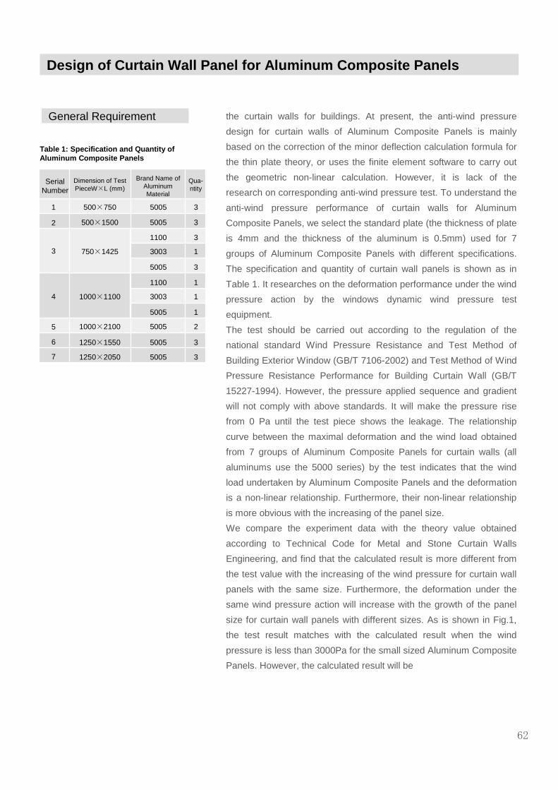
General Requirement the curtain walls for buildings. At present, the anti-wind pressure
design for curtain walls of Aluminum Composite Panels is mainly
based on the correction of the minor deflection calculation formula for
the thin plate theory, or uses the finite element software to carry out
the geometric non-linear calculation. However, it is lack of the
research on corresponding anti-wind pressure test. To understand the
anti-wind pressure performance of curtain walls for Aluminum
Composite Panels, we select the standard plate (the thickness of plate
is 4mm and the thickness of the aluminum is 0.5mm) used for 7
groups of Aluminum Composite Panels with different specifications.
The specification and quantity of curtain wall panels is shown as in
Table 1. It researches on the deformation performance under the wind
pressure action by the windows dynamic wind pressure test
equipment.
The test should be carried out according to the regulation of the
national standard Wind Pressure Resistance and Test Method of
Building Exterior Window (GB/T 7106-2002) and Test Method of Wind
Pressure Resistance Performance for Building Curtain Wall (GB/T
15227-1994). However, the pressure applied sequence and gradient
will not comply with above standards. It will make the pressure rise
from 0 Pa until the test piece shows the leakage. The relationship
curve between the maximal deformation and the wind load obtained
from 7 groups of Aluminum Composite Panels for curtain walls (all
aluminums use the 5000 series) by the test indicates that the wind
load undertaken by Aluminum Composite Panels and the deformation
is a non-linear relationship. Furthermore, their non-linear relationship
is more obvious with the increasing of the panel size.
We compare the experiment data with the theory value obtained
according to Technical Code for Metal and Stone Curtain Walls
Engineering, and find that the calculated result is more different from
the test value with the increasing of the wind pressure for curtain wall
panels with the same size. Furthermore, the deformation under the
same wind pressure action will increase with the growth of the panel
size for curtain wall panels with different sizes. As is shown in Fig.1,
the test result matches with the calculated result when the wind
pressure is less than 3000Pa for the small sized Aluminum Composite
Panels. However, the calculated result will be
Table 1: Specification and Quantity of Aluminum Composite Panels
SerialNumber
1
2
3
4
5
6
7
Dimension of Test PieceW×L (mm)
500×750
500×1500
750×1425
1000×1100
1000×2100
1250×1550
1250×2050
Brand Name of Aluminum Material
5005
5005
3003
3003
5005
5005
5005
1100
5005
1100
5005
3
3
1
1
2
3
3
3
3
1
1
Qua-ntity
62
Design of Curtain Wall Panel for Aluminum Composite Panels

General Requirement different from the test result much more with the increasing of the wind
pressure. For Aluminum Composite Panels with large curtain wall
panel size, the wind pressure deformation obtained by the
specification JGJ133-2001 will be different from the result by the test.
Hence, we can come to a conclusion that the calculation formula used
by JGJ133-2001 after the correction of the reduced coefficient is
applicable to calculate the deflection for the small sized curtain wall
panel under the wind pressure action, but not applicable for the large
sized curtain wall panel and large wind pressure situation.
Furthermore, it will increase the materials greatly and cause the
waste. For above reasons, we put forward another design method to
set the reinforced rib in the appendix in Specification for Construction
and Acceptance of Aluminum Composite Panel Curtain Walls
Engineering. Namely, it will refer to the relationship of the bending
deflection and the curtain wall panel size (setting of the reinforced rib)
for Aluminum Composite Panels in Appendix A.
4. The bending stress standard value on the supporting line of the
middle rib can use the average of the calculated result for two sides of
curtain wall panels.
5. The maximal stress standard value generated under various loads
and actions in curtain wall panels should be combined according to
the regulation, and the obtained maximal stress design value should
not exceed the design value of the curtain wall strength.
63
[Description] Regardless of the side rib, the perimeter of the metal
plate can cause the rotation, so it can be considered as the simply-
supported edge for the calculation. The wind load and earthquake
action is even distributed for curtain wall panels, and the panel division
at both sides of the middle rib undertakes the force. If the spans are
equal to or close to for each other, it will not cause obvious panel
rotation, so it can be considered as the fixed edge for the calculation.
When the non-linear finite element method is used to calculate the
panels with ribs, the constraint condition of the side rib can consider
the line displacement in the direction vertical to panels as zero.
0 1000 2000 3000 4000 5000 60000
1
2
3
4
5
6
7
8
9
10
最大变形
(m
m)
风压 (Pa)
试验结果 JGJ133-2001计算结果
0 1000 2000 3000 4000 5000 60000
5
10
15
20
25
30
35
40
45
最大变
形 (
mm
)
风压 (Pa)
试验结果 JGJ133-2001计算结果
0 1000 2000 3000 4000 5000 60000
20
40
60
80
100
120
140
160 试验结果 JGJ133-2001计算结果
最大
变形
(m
m)
a.500×750mm,5005series
b.750×1425mm,5005series
c.1250×1550mm, 5005series
Fig.1 Comparison of Test Result with
JGJ133 Calculated Result
风压 (Pa)
Table 2: Reduced Coefficient
5
1.00
10
0.95
20
0.90
40
0.81
60
0.74
80
0.69
100
0.64
120
0.61
150
0.54
200
0.50
250
0.46
300
0.43
350
0.41
400
0.40
Design of Curtain Wall Panel for Aluminum Composite Panels

General Requirement The calculation formula of the elastic thin panel is as follows:
64
Table 1: Specification and Quantity of Aluminum Composite Panels
SerialNumber
1
2
3
4
5
6
7
Dimension of Test PieceW×L (mm)
500×750
500×1500
750×1425
1000×1100
1000×2100
1250×1550
1250×2050
Brand Name of Aluminum Material
5005
5005
3003
3003
5005
5005
5005
1100
5005
1100
5005
3
3
1
1
2
3
3
3
3
1
1
Qua-ntity
Above formula supposes the deformation of panels is the small
deflection, and panels only undertake the bending action and generate
the bending stress, but the film stress within the surface is neglected.
Hence, the scope of application for the formula is that the deflection is
not greater than the thickness of panels (namely, ≤t). When the
deflection of panels is greater than the thickness of panels, this
calculation formula will generate obvious error, namely the calculated
stress and deflection are greater than that in the actual condition.
With the increasing of the deflection and the thickness of panels, the
calculated stress and deflection will be so great that it can not be
accepted by the project, so it is meaningless for the calculation. The
design of panels by the larger calculated result will increase the
materials greatly, and make the specified stress and deflection control
condition meaningless.
In general, the deflection of the metal plate is allowed to be 1/60 of the
side length. For the aluminum plate with the section division side
length 500mm and thickness 3mm, the allowed 8mm of the deflection
value exceeds 2 times of the panel thickness. At this time, the
calculated value of the deflection is 50 – 80 percent greater than the
actual value. The control is stricter than the anticipated control value
by letting the calculated deflection less than 1/60 of the side length.
There is the similar situation for the calculation of the bearing
capacity.
For above reason, the calculation of the metal plate should take
appropriated reduction of the calculated result for the stress and
deflection under current small deflection condition (Table 2).
The calculation of large deflection panels is a rather complicated non-
linear elastic mechanic problem and it is hard to be expressed by a
simple formula, so it is necessary to use the dedicated calculation
method and software for the calculation on the concrete problem.
Obviously, it is not convenient to be used in curtain walls engineering
design generally.
Design of Curtain Wall Panel for Aluminum Composite Panels

General Requirement Englisher B.Aalami and D.G.williams systematically calculate the
rectangular thin plate with different borders and issue the Thin Plate
Design for Transverse Loading. We appropriately simplify and merge
the content according to a large number of calculated resulted for the
convenience of the actual application, and select the parameter that
is directly related to the deflection as the main variant, and compile
with Table 3 of this specification. The dimension of the parameter is
the ratio of the deflection to the thickness:
65
As is shown in Table 2, the modified coefficient η will be reduced
quickly with the . Namely, the stress and deflection calculated by the
small deflection formula will be reduced much. For the sake of
security, we get the value with large result in Table 3 to remain
enough margin. At the same time, similar reduced coefficient η
(Table 2) should be taken into account when we calculate the
deflection d f of panels.
For the effect of the Poisson ratio on the stress and deflection
calculation of panels is limited, the reduced coefficient is applicable
to calculate the stress and deflection of different metal plates in
principle.
Table 3: Reduced Coefficient η of Stress σ Calculated Result for Elastic Small Deflection Formula
0=qa4
Et4
Calculated Result of B.Aalami and D.G.williams, Side Length Ratio
≤≤≤≤l
10
20
40
120
200
300
≥≥≥≥400
1.000
0.975
0.965
0.803
0.480
0.350
0.285
0.241
1.000
0.904
0.814
0.619
0.333
0.235
0.175
0.141
1.000
0.910
0.820
0.643
0.363
0.260
0.195
0.155
1.00
0.95
0.90
0.8l
0.6l
0.50
0.43
0.40
1.0 1.5 2.0
Value in Table 7.1.3 of This Specification
Design of Curtain Wall Panel for Aluminum Composite Panels

General Requirement Table 4: Reduced Coefficient η of Stress σ Calculated Result for Elastic
Small Deflection Formula
Aluminum Composite Panels is the three-layer sandwich panel and
the mechanic performance for various layers of materials is different,
so the mechanical characteristics of panels is expressed by the
equivalent section modulus We and the equivalent rigidity De for the
calculation of the stress and deflection. The equivalent section
modulus We and equivalent rigidity De are obtained from the bend
test of sandwich panels.
When we calculate its parameter , the denominator in the formula 7.3-
3 should use or appropriately use instead. Where, v gets
0.25.
0=qa4
Et4
Calculated Result of B.Aalami and D.G.williams, Side Length Ratio is
≤≤≤≤l
10
20
40
120
200
300
≥≥≥≥400
1.000
0.955
0.965
0.803
0.482
0.375
0.304
0.201
1.000
0.906
0.814
0.619
0.394
0.304
0.245
0.209
1.000
0.916
0.820
0.643
0.417
0.322
0.252
0.211
1.00
0.95
0.90
0.8l
0.6l
0.50
0.43
0.40
1.0 1.5 2.0
Value in Table 7.1.3 of This Specification
66
6. The calculation of deflection for curtain wall panels of Aluminum
Composite Panels under the wind load:
The span center deflection of Aluminum Composite Panels can be
calculated by the geometric non-linear finite element method or by the
following formula:
Where, is the equivalent bending rigidity .
Under the action of the standard wind load value, the limit value of the
panel deflection should use 1/60 of the side length for the
section division calculation.
Design of Curtain Wall Panel for Aluminum Composite Panels

General Requirement III. Design of Reinforced Rib
67
1. The load applied to the curtain wall panel block of Aluminum
Composite Panels can be transferred to the rib by the triangle or
trapezoid distribution. It can be converted into the equivalent even
distributed load by the equal moment rule for the calculation of ribs.
2. The side rib section size of Aluminum Composite Panels can be
designed according to the structural requirement. The single span
middle rib can be designed by the simply-supported beam. The
multiple-span middle rib can be analyzed by the beam series of
calculation software.
3. The reinforced middle rib should be equipped with enough rigidity,
and it can use the metal square tube, slotted or angle material. The
section thickness of the reinforce rib should not be less than 1.5mm.
Furthermore, the maximal deflection value under the wind load
standard value should not be greater than 1/120 of the distance for its
supporting point.
Connection Design of Middle Ribs and Curtain Wall Panels
IV. Connection Design of Middle Ribs and Curtain
Wall Panels
1. The silicone structure sealant is used to carry out the bonding
connection for middle ribs and curtain wall panels. The connection
structure and calculation should meet the requirement for the use of
silicone structure sealants.
2. The structural bonding tape is used to carry out the bonding
connection for middle ribs and curtain wall panels. The connection
structure and calculation should meet the requirement for the use of
structural bond tapes.
V. Installation Design of Curtain Wall Panels
1. Curtain wall panels of Aluminum Composite Panels can use the bolt,
flange or hook to fix in the beam or column. The diameter of fixing
bolts should not be less than 4mm, and the quantity of bolts should be
determined by the calculation according to the wind load and
earthquake action undertaken by the curtain wall panels. The hook
should be equipped with the anti-noise gasket.
[Description] Curtain wall panels of Aluminum Composite Panels can
take the bolt or flange connection method to fix in the beam or column
along
Installation Design of Curtain Wall Panels
Design of Curtain Wall Panel for Aluminum Composite Panels

Installation Design of Curtain Wall Panels
1. The width of the connection panel seam for curtain walls block for
Aluminum Composite Panels should meet the requirement of
necessary spacing during the installation and construction. At the
same time, it should be applicable to the deformation of curtain walls
themselves and buildings under various forces. The width of the
curtain wall panel seam should not be less than 8mm. The depth of
the curtain wall panel seam should be determined according to the
operability of the construction and the spacing required for the filling
material.
2. The injected sealing panel seam and the sealing should meet the
following requirements:
1 The bottom of the curtain wall panel seam should be filled by the
foam strip. The curtain wall panel seam should use the silicone
sealant fillet for buildings, the thickness of the sealant should not be
less than 3.5mm, and the width should not be less than 2 times of the
thickness.
68
the perimeter, or take the hook connection method to fix in the beam
or column along both sides. The diameter of fixing bolts should not be
less than 4mm, and the quantity of bolts should be determined by the
calculation according to the wind load and earthquake action
undertaken by curtain wall panels. The hook should be equipped with
the anti-noise gasket.
2. The thickness of hanging parts or angle rulers for curtain wall
panels for Aluminum Composite Panels should not be less than 3mm,
and the material can select the aluminum ally or steel that complies
with current national standard. The rivet or anchor bolt for the
connection of hanging parts or angle rulers with curtain wall panels
should use the stainless steel material, and the diameter and quantity
of the rivet, screw or bolt should be determined by the calculation. The
distance from the center of the rivet, screw or bolt holes to the edge of
the curtain wall panels should not be less than 2 times of the aperture,
and the center distance of the hole should not be less than 3 times of
the aperture.
VI. Curtain Wall Panel Seam and Seal DesignCurtain Wall Panel Seam and Seal Design
Design of Curtain Wall Panel for Aluminum Composite Panels

69
2. The silicone sealant for buildings of the coats surface should
carry out the compatibility test, and paint the primer if necessary.
[Description] The injected sealing panel seam is a common used fillet
format for it can provide reliable air tightness and water tightness.
Various contractors are familiar with it and the construction quality can
be ensured. The general project may take priority for the injected
panel seam.
The bond performance of the silicone buildings sealant for the
fluorocarbon coats of Aluminum Composite Panels is related to the
manufacturer and brand name of sealants. Hence, the bonding
performance should be tested in advance. Furthermore, the coating of
primers is a measure to improve the seal bonding performance of
some brand name. However, it is not necessary for each sealant and
is not certain to play a role in each sealant. So it should be determined
by the test.
3. The embedded sealing panel seam and the sealing should meet the
following requirements:
1 The contact of the sealing piece and sealing panel seam should
be tight, or corresponding clamp is designed to prevent the peeling of
the sealant strip. The crossing point of sealant strips should use
sealants with special design to seal, or take other methods to ensure
the reliability of the sealing.
2 Use the embedded sealing. It should carry out the multi-cavity
and multi-channel sealing waterproof design according to the rain
curtain principle, and set the drainage structure.
[Description] The water tightness of the embedded panel seam
depends on the quality of the embedded panel seam and rational
design of the equal pressure cavity. The embedded panel seam
should provide enough elasticity and endurance. In general, we use
two or three embedded panel seams to form one or two equal
pressure cavities, sp as to prevent the rain penetration.
4 The open panel seam should comply with the following
requirements:
1 The back of the open panel seam should prevent the water
accumulation, and necessary drainage structure should be set to
ensure the smooth drainage.
2 The insulating material of the buildings main body wall should
take the waterproof and moisture proof measure, and it can take the
zinc coated
Curtain Wall Panel Seam and Seal Design
Design of Curtain Wall Panel for Aluminum Composite Panels

steel plate or aluminum plate as the waterproof lining plate.
3 The back space of the decoration layer for Aluminum Composite
Panels should keep ventilation to discharge the damp water vapor
smoothly.
4 The supporting structure and metal connector should take
effective anti-corrosive measure.
[Description] The open panel seam without sealing measure will make
rain penetrate into the back space of the plate. Hence, it is necessary
to take several measures to get rid of the effect. For instance, the
drainage channel is used to discharge the accumulated water as soon
as possible, increase the rear ventilation to make the remaining water
content vapor and use the additional metal plate waterproof layer. For
there is some water content and damp inevitably, the rear steel
structure should take the anti-corrosive measure.
5. Aluminum Composite Panels with the open panel seam should use
the aluminum alloy folding edge, to prevent the core material exposes
to the external atmosphere directly, or use the embedded Aluminum
Composite Panel edge of the aluminum alloy frame, and take the
flange to fix it in the beam and column.
Curtain Wall Panel Seam and Seal Design
70
Design of Curtain Wall Panel for Aluminum Composite Panels

Sealing Material
Sealing Material Sealing Material
1. The rubber product for curtain walls of Aluminum Composite
Panels should use the EPDM, chloroprene rubber and silicone
rubber.
[Description] At present, the sealing of domestic dry seam curtain
wall mainly uses the rubber sealing strip to play the sealing role in
the slotting depending on the elasticity of the rubber strip itself. The
rubber strip is required to provide the characteristics of the
ultraviolet resistance, degradation resistance and small permanent
deformation and stain resistance. Several domestic large-scale
projects use the rubber strip sealing and not any problem takes
place up to now. However, if the quality of materials is not
controlled strictly, some rubber interface may result in the quality
problem within 1 or 2 years. For example, it may cause the
degradation and cracking or even peeling to make the water and air
leakage from curtain walls, and the panel may also peel and cause
the hidden hazard for curtain walls. Hence, the unqualified sealing
rubber strip is not allowed to use for curtain walls. Using the
silicone rubber with excellent weather resistance and small
permanent deformation as the sealing rubber strip is a
development direction.
2. The sealing rubber strip should comply with the regulation of
current national standard Rubber Building Gaskets--Materials for
Preformed Solid Vulcanized Structural Gaskets Specification HB/T
3099 and Industrial Rubber Sheet GB/T 5574.
The curtain walls of Aluminum Composite Panels should use the
neutral weather resistance sealant, whose performance should
comply with the regulation of current national standard Silicone
Sealants for Building GB/T 14683.
[Description] The weather resistance sealant for curtain walls of
Aluminum Composite Panels should use the neutral silicone
weather resistance sealant for its super ultraviolet resistance
performance and excellent compatibility with the silicone structural
sealant. The acidic silicone sealant should not be used for it will
release the acetic acid during the curing and play the corrosive role
in the aluminum plate and film layer and react with the calcium
carbonate in the neutral silicone structural sealant.
■
■
71
■

Sealing Material
Silicone Structural Sealant Silicone Structural Sealant
1. The performance of the neutral silicone structural sealant for
curtain walls should comply with the regulation of current national
standard Structural Silicone Sealants for Building GB 16776.
[Description] The silicone structural sealant is an important factor
that will affect the safety of curtain walls. Our nation issued the
national standard about the silicone structural sealant Structural
Silicone Sealants for Building GB 16776 in 1997. GB 16776 is
worked out on the basis of ASTM C1184 and specifies the most
basic requirement of the silicone structural sealant. In 2002, GB
16776 was revised and the requirement of the elastic modulus and
maximal extension ratio was added according to the use condition
of the silicone structural sealant in recent years.
2. Before the use of the silicone structural sealant, the compatibility
with its contact material and adhesion-in-peel test should be carried
out by the national recognized test institution.
[Description] Before the use of the silicone structural sealant, the
adhesion-in-peel of Aluminum Composite Panels and metal frame
test and the compatibility with the spacing strip, sealing gasket,
positioning block and other contact sealant test should be carried
out. It can be used only when the adhesion-in-peel and
compatibility test is qualified. If the material used is not compatible
with the structural sealant, it may cause the reduction or loss of the
bonding strength and bonding performance for the structural
sealant, and remain a large number of hidden hazards.
To ensure the performance of structural sealants meets the
standard requirement and prevent the counterfeit product from
entering into the field, this clause specifies to carry out the re-
examination for partial performance of the structural sealant. The
re-examination should be carried out after the material enters into
the field by the test institution with corresponding qualification. Only
the qualified product can be used.
3. The silicone structural sealant manufacturer should provide the
position change bearing capacity of the structural sealant and the
quality certificate.
[Description] The position change bearing capacity of the silicone
structural sealant is the assistant basis of its intensity index with the
same importance, and is an important guarantee of the relative
displacement
■
■
■
72
■

Sealing Material
Silicone Structural Sealant Silicone Structural Sealant
capacity and reliability for curtain walls. Furthermore, it is also an
important parameter for the calculation of the structural sealant
seam thickness in this specification. In main domestic and foreign
products, this index is usually greater than 0.15.
Other Materials
1. Other materials used for curtain walls of Aluminum Composite
Panels should comply with various requirements of JGJ 133
Technical Code for Metal and Stone Curtain Walls Engineering and
related material standard. The bonding performance of the
structural dual-side bonding tape should meet the design
requirement.
[Description] This specification specifies the requirement of the
main material for curtain walls of Aluminum Composite Panels.
Other general materials of curtain walls, such as the aluminum
material, steel, fittings, insulating material, should meet
corresponding requirement in JGJ 133 Technical Code for Metal
and Stone Curtain Walls Engineering.
■
■
73

Sealing Material
Connection Design of Curtain
Wall Components and Main
Body Structures
1. The main body structure or structural component should be able
to undertake the load and action transferred by curtain walls. The
design value of the anchoring bearing capacity for the connection
component and main body structure should be greater than the
design value of the bearing capacity for the connection component
itself.
[Description] The connection and anchoring of curtain walls should
be reliable, and the bearing capacity should be determined by the
calculation or the real test, and some margin should be maintained
to prevent the sudden damage by the accidental factor. The
anchoring bearing capacity of the connection component and main
body structure should be greater than that of the connection
component itself. In any case, the anchoring is not allowed to be
damaged.
The main body structure for the curtain wall installation should
provide the capacity to undertake various actions transferred from
curtain walls, which should be taken into account fully for the
design of the main body structure. If the main body structure is the
concrete structure, the intensity of the concrete is related to the
reliable work of the anchoring component. In addition to improve
the management of the project quality for the concrete construction,
it also puts forward for the minimal intensity level of the concrete.
To ensure the connection reliability of the main body structure, the
intensity of the main body structure concrete for connection parts
should not be less than C20.
2. The design of the connector, weld bead, bolt and rivet at the
connection point of curtain wall components should comply with
related regulation of current national standard Code for Design of
Steel Structures GB50017, Technical Code for Design of Cold-
formed Thin-wall Steel Structures GB50018 and Technical
Specification for Steel Structure of Tall Buildings JGJ99. The bolt
and rivet undertaken the force at the connection point should not be
less than 2.
[Description] The connection between the beam and column of
curtain walls and the connection between the column and
anchoring component or the main body structure steel beam and
steel material are usually implemented by the bolt, weld bead or
rivet. At the same time, and the tension and shearing design should
be carried out for the tensile and sheared bolt.
■
■
74

Connection Design of Curtain Wall Components and Ma in Body Structures
Connection Design of Curtain
Wall Components and Main
Body Structures
5. For the stressed embedded parts that consist of the anchor plate
and the anchoring steel bar in the symmetric position, it can be
designed according to the regulation of JGJ133.
[Description] JGJ133 puts forward general regulation for the
embedded part design of curtain walls. The requirement for the
embedded parts mainly complies with related research outcomes
and existing national standard Code for Design of Concretes
GB50010.
1. The shearing bearing capacity of the shearing embedded parts is
related to the intensity level, the strength, the arrangement method
and diameter of steel bars.
2. For the embedded parts that suffer from the normal tensile force,
the anchoring bar undertakes both the tensile force and the internal
shearing force caused by the bending deformation of the steel plate,
to make the anchoring bar be in the combined stress status when
the steel plate bends and deforms. Hence, the reduced coefficient
of the anchoring plate bending and deformation is introduced into
the calculation formula.
3. For the embedded parts that undertake the bending moment, the
test indicates that the resultant force point at the stressed area
usually exceeds the edge bar at the stressed area. For the
convenience and safety, the bending force arm gets the distance
between the center lines of the external anchoring bars.
Furthermore, the reduced coefficient of the anchoring plate bending
and deformation is introduced into the calculation formula.
4. For the embedded parts that undertake the tensile force,
shearing force, or tensile force and bending moment, their bearing
capacities are supposed to be linear interrelated.
5. For the embedded parts that undertake the shearing force and
bending moment, when V/Vu0>0.7, the shearing bearing capacity
is linear interrelated with the bending bearing capacity, and when
V/Vu0≤0.7, the shearing bearing capacity is not interrelated with
the bending bearing capacity according to the test result. Where,
Vu0 is the shearing bearing capacity when the embedded part
undertakes the shearing action individually.
■
75
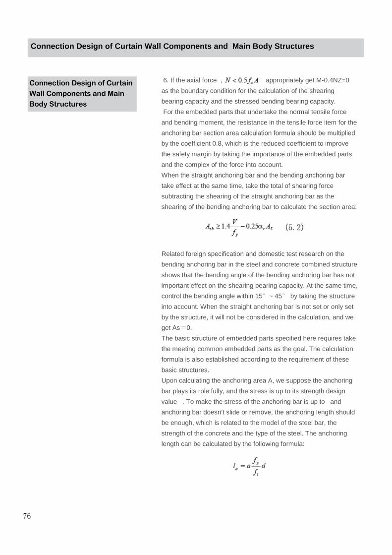
Connection Design of Curtain
Wall Components and Main
Body Structures
6. If the axial force , appropriately get M-0.4NZ=0
as the boundary condition for the calculation of the shearing
bearing capacity and the stressed bending bearing capacity.
For the embedded parts that undertake the normal tensile force
and bending moment, the resistance in the tensile force item for the
anchoring bar section area calculation formula should be multiplied
by the coefficient 0.8, which is the reduced coefficient to improve
the safety margin by taking the importance of the embedded parts
and the complex of the force into account.
When the straight anchoring bar and the bending anchoring bar
take effect at the same time, take the total of shearing force
subtracting the shearing of the straight anchoring bar as the
shearing of the bending anchoring bar to calculate the section area:
Related foreign specification and domestic test research on the
bending anchoring bar in the steel and concrete combined structure
shows that the bending angle of the bending anchoring bar has not
important effect on the shearing bearing capacity. At the same time,
control the bending angle within 15°~ 45° by taking the structure
into account. When the straight anchoring bar is not set or only set
by the structure, it will not be considered in the calculation, and we
get As=0.
The basic structure of embedded parts specified here requires take
the meeting common embedded parts as the goal. The calculation
formula is also established according to the requirement of these
basic structures.
Upon calculating the anchoring area A, we suppose the anchoring
bar plays its role fully, and the stress is up to its strength design
value . To make the stress of the anchoring bar is up to and
anchoring bar doesn’t slide or remove, the anchoring length should
be enough, which is related to the model of the steel bar, the
strength of the concrete and the type of the steel. The anchoring
length can be calculated by the following formula:
76
Connection Design of Curtain Wall Components and Ma in Body Structures

Connection Design of Curtain
Wall Components and Main
Body Structures
5. For the stressed embedded parts that consist of the anchor plate
and the anchoring steel bar in the symmetric position, it can be
designed according to the regulation of JGJ133.
[Description] JGJ133 puts forward general regulation for the
embedded part design of curtain walls. The requirement for the
embedded parts mainly complies with related research outcomes
and existing national standard Code for Design of Concretes
GB50010.
1. The shearing bearing capacity of the shearing embedded parts is
related to the intensity level, the strength, the arrangement method
and diameter of steel bars.
2. For the embedded parts that suffer from the normal tensile force,
the anchoring bar undertakes both the tensile force and the internal
shearing force caused by the bending deformation of the steel plate,
to make the anchoring bar be in the combined stress status when
the steel plate bends and deforms. Hence, the reduced coefficient
of the anchoring plate bending and deformation is introduced into
the calculation formula.
3. For the embedded parts that undertake the bending moment, the
test indicates that the resultant force point at the stressed area
usually exceeds the edge bar at the stressed area. For the
convenience and safety, the bending force arm gets the distance
between the center lines of the external anchoring bars.
Furthermore, the reduced coefficient of the anchoring plate bending
and deformation is introduced into the calculation formula.
4. For the embedded parts that undertake the tensile force,
shearing force, or tensile force and bending moment, their bearing
capacities are supposed to be linear interrelated.
5. For the embedded parts that undertake the shearing force and
bending moment, when V/Vu0>0.7, the shearing bearing capacity
is linear interrelated with the bending bearing capacity, and when
V/Vu0≤0.7, the shearing bearing capacity is not interrelated with
the bending bearing capacity according to the test result. Where,
Vu0 is the shearing bearing capacity when the embedded part
undertakes the shearing action individually.
■
77
Connection Design of Curtain Wall Components and Ma in Body Structures

Connection Design of Curtain
Wall Components and Main
Body Structures
Where, is the anchoring length of the tensile steel bar (mm).
is the design value of the tensile strength for the concrete axis
center, it gets the value according to existing national standard
Code for Design of Concretes 50010. When the strength of
concretes is higher than C40, we get C40.
is the nominal diameter of anchoring bars (mm).
is the shape coefficient of anchoring bars. We get 0.16 for the
round steel bar and 0.14 for the steel bar with ribs.
Sometimes, it is hard to use curtain wall embedded parts for the
value is too large. Hence, we use the low stress design method,
namely, increase the area of the anchoring bar and reduce the
actual stress of the anchoring bar, to shorten the anchoring length.
However, the anchoring length should not be less than 15 times of
the steel bar diameter.
6. The embedded steel plate of the slotted embedded parts and
other connection measures should be designed according to
related regulation of existing national standard Code for Design of
Steel Structures GB50017.
7. The anchor bolt connection for curtain walls frame and main
body structure should comply with the following regulation:
1 The products should be equipped with the leave-factory
certificate.
2 The anti-corrosion processing should be carried out for the
anchoring bolt of the carbon steel.
3 The field test of the bearing capacity should be carried out, and
the pull-out test should be carried out, if required.
4 Each connection node should not be equipped with the anchor
bolts less than 2.
5 The diameter of anchor bolts should be determined by the
calculation of the bearing capacity and should not be less than
10mm.
6 The welding operation should not be carried out on the
connector that contacts with the chemical anchor bolts.
7 The design value of the bearing capacity for anchor bolts
should not be greater than 50 percent of its limit bearing capacity.
[Description] If no embedded part is set and the embedded part is
missed in civil engineering, or the embedded part offsets the design
position too
■
■
78
Connection Design of Curtain Wall Components and Ma in Body Structures

Connection Design of Curtain
Wall Components and Main
Body Structures
much, or the design is changed, or the old building is added with
curtain walls, it is usually necessary to be connected by the post
anchor bolt. When the post anchor bolt (mechanical or chemical
anchor bolt) is used, several measures should be taken to ensure
the reliability of connection.
8. When curtain walls are connected with the masonry structure,
the steel bar concrete or steel structural beam and column should
be set on the main body structure of connection parts. The light
filling wall should not be taken as the supporting structure of curtain
walls.
[Description] The bearing capacity outside of the masonry structure
plane is low and it is hard to be connected directly. Hence, the
concrete structure or steel structure connection component should
be added. The bearing capacity and deformation capacity of the
light partition wall is low and should not be taken as the supporting
structure of curtain walls.
■
79
Connection Design of Curtain Wall Components and Ma in Body Structures

Endurance and Safety Performance
Endurance and Safety
Performance
1. The color of the paint baking for Aluminum Composite Panels is
allowed to change with the time, and it will show slight and even
change in the same facade. However, the long term performance
test should be carried out according to the nation standard of the
fluorocarbon paint and customers should be provided with 10 years
or more quality assurance (For the details on the test method and
index requirement, refer to the clause 3.2.3 in athis specification).
[Description] The surface endurance performance of curtain walls
for Aluminum Composite Panels mainly depends on the color of
products, the use location, environment and direction. The variation
of effect factors causes the slight difference of the degradation
speed of curtain wall panels. However, the degradation condition
should be same under the same factor, and the change condition
(such as fading) should be even.
2. The fireproof design of curtain walls for Aluminum Composite
Panels should comply with related regulation of existing national
standard Code of Design on Building Fire Protection and
Prevention GB50016, and the curtain wall fireproof of tall buildings
should comply with related regulation of existing national standard
Code for Fire Protection Design of Tall Buildings GB 50045.
[Description] The curtain wall fireproof of Aluminum Composite
Panels is not specified in the Code of Design on Building Fire
Protection and Prevention GB 50016 definitely. However, it puts
forward some fireproof regulation for the building material and
different parts of the building. When curtain walls are in these parts,
related requirement should be met.
It specified the building curtain wall in the Code for Fire Protection
Design of Tall Buildings GB 50045 definitely, and it should be
complied with.
3. The fireproof sealing design should be designed for the seam
between the curtain wall and surrounding fireproof partition
members, the seam between the curtain wall panel or partition wall
outer space and the seam between the real wall surface opening
edges.
[Description] Although curtain walls of Aluminum Composite Panels
themselves don’t provide special fireproof capacity, it is a part of
the whole building as the external envelope structure. Some
important parts should provide a certain fire resistance, and comply
with the whole fireproof requirement of the building.
■
■
■
80

Endurance and Safety
PerformanceThe fireproof sealing is a fire protection and smoke isolated method
with broad application for current building design, which is formed
by filling the material that is not inflammable or fire resistant in the
seam, to reach the goal that prevents the flame and high
temperature flue gas and noxious gas from spreading in buildings.
4. The smoke protection and fireproof sealing structural system of
curtain walls should provide the sealing and endurance. If it
catches fire, the integrity should be maintained within the specified
fire resistance limit.
[Description] The endurance, adaptable capacity of the deformation
and stability is the basic requirement of the fireproof sealing
material or system, which should be integrated considered and
rationally selected according to the width amd property of the seam
(for example, whether the extension/contraction deformation takes
place), material quality of adjacent members, other surrounding
environment factors and design requirements. In general, the larger
of the seam, the larger of the extension/contraction and the higher
the fireproof level, the higher the requirement of the fireproof
sealing material or system is.
5. The fireproof sealing system should use the non-inflammable or
fire retardant material that complies with the requirement.
[Description] The fireproof sealing structural system of curtain walls
provides several effective fabrication methods. Regardless of any
methods, the material made of the system should provide the fire
resistance performance specified in the design.
6. The seam between the curtain wall and floor slab compartment
can use the rock wool or mineral wool sealing. The thickness of the
rock wool and mineral wool should not be less than 100mm, and
should be filled tightly. The thickness of the rock wool and mineral
wool between the floors should use the zinc coated steel sheet with
the thickness no less than 1,5mm, and the seam between the
bearing board and other structures should be filled with the
fireproof sealing material.
[Description] The bearing board of the fireproof sealing should use
the anti-corrosive processing steel plate with the thickness no less
than 1.5mm, but not use the single aluminum plate or Aluminum
Composite Panels.
■
■
■
81
Endurance and Safety Performance

Endurance and Safety
Performance
7. The lightning protection design of curtain walls for Aluminum
Composite Panels should comply with related regulation of existing
national standard Code for Protection of Structures against
Lightning GB 50057 and Code for Electrical Design of Civil
Buildings JGJ/T 16. The member as the lightning protection
network in the metal frame of curtain walls should be connected
with the lightning protection system of the main body structure
reliably. For the building with the requirement of the
electromagnetic shield or using the common grounding protection,
the lightning design of its curtain walls should comply with related
requirement of Protection against Lightning Electromagnetic
Impulse - Part 1: General principles GB/T 19271.1.
[Description] Existing national standard Code for Protection of
Structures against Lightning GB 50057 doesn’t put forward the
regulation on the curtain wall lightning protection concretely and
definitely.
The curtain wall of Aluminum Composite Panels is the envelope
structure that is attached to the main building. The metal frame of
curtain walls is usually not taken as the lightning protection
grounding, but makes use of the lightning protection system of the
main body structure and combines with the lightning protection
design of the building itself. Hence, it is required to be connected
with the lightning protection system of the main body structure
reliably, and keep the conduction smooth.
In general, the column of curtain walls should use the flexible cable
to connect with each other. For the floor whose main building has
the horizontal grading ring, the embedded parts or fittings of the
column should use the circular steel or flat steel to connect with the
horizontal grading ring welding, to form the conduction path. The
welding seam and the connection cable should be coated with the
antirust paint. The section area of the flat steel should not be less
than 5mm×40mm, and the diameter of the circular steel should not
be less than 12mm.
The curtain wall key roof stratum with the lightning protection
function should be made by using the aluminum alloy plate with the
thickness no less than 3mm, the section area of the key roof
stratum should not be too small. The curtain wall key roof stratum
system should be effectively connected with the lightning protection
system of the main body structure roof.
82
Endurance and Safety Performance
Endurance and Safety
PerformanceFor the building with the electromagnetic protection requirement,
the Protection against Lightning Electromagnetic Impulse - Part 1:
General principles GB/T 19271.1 requires the metal members with
large size, such as the metal window, carry out the equi-potential
connection with the lightning protection system (LPS), and the
protection network formed by the metal member should not be too
large. For the equi-potential connection, this standard puts forward
a certain requirement that should be met for the lightning protection
design of curtain walls.
8. For the endurance of curtain walls for open Aluminum Composite
Panels, in addition to above-mentioned whole endurance
performance, it should be noted to take the long-term surface
treatment quality, the matching with the surface paint baking of
Aluminum Composite Panels and preventing the rust from affecting
the performance into account. Furthermore, it should also be noted
to consider the endurance of the internal fixation for the curtain
walls, connection and installation of assistant fittings. If the
surrounding environment of buildings is special, such as the
seaside and corrosive air (such as the building within the industrial
pollution area), it is necessary to use the material with superior
endurance.
■
83
Endurance and Safety Performance
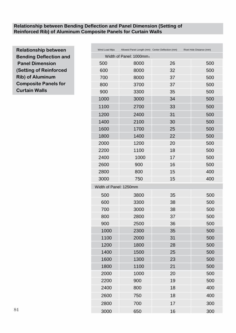
Relationship between Bending Deflection and Panel D imension (Setting of Reinforced Rib) of Aluminum Composite Panels for Cu rtain Walls
Relationship between
Bending Deflection and
Panel Dimension
(Setting of Reinforced
Rib) of Aluminum
Composite Panels for
Curtain Walls
Wind Load Mpa Allowed Panel Length (mm) Center Deflection (mm) Rivet Hole Distance (mm)
Width of Panel: 1000mm:
500 8000 26 500
600 8000 32 500
700 8000 37 500
800 3700 37 500
900 3300 35 500
1000 3000 34 500
1100 2700 33 500
1200 2400 31 500
1400 2100 30 500
1600 1700 25 500
1800 1400 22 500
2000 1200 20 500
2200 1100 18 500
2400 1000 17 500
2600 900 16 500
2800 800 15 400
3000 750 15 400
500 3800 35 500
600 3300 38 500
700 3000 38 500
800 2800 37 500
900 2500 36 500
1000 2300 35 500
1100 2000 31 500
1200 1800 28 500
1400 1500 25 500
1600 1300 23 500
1800 1100 21 500
2000 1000 20 500
2200 900 19 500
2400 800 18 400
2600 750 18 400
2800 700 17 300
3000 650 16 30084
Width of Panel: 1250mm
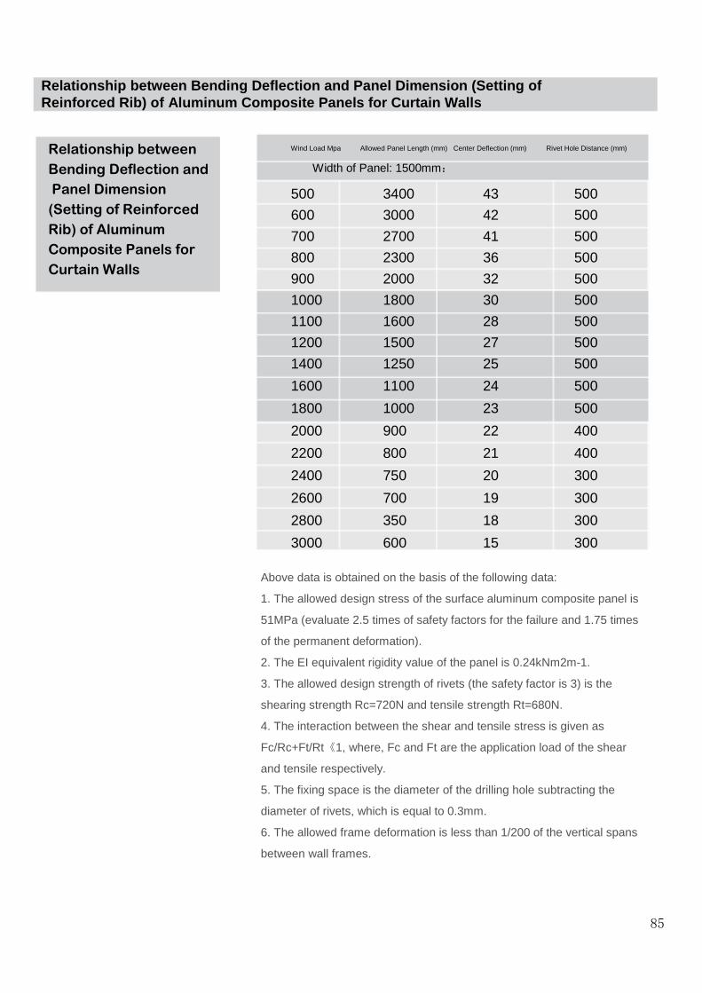
Relationship between
Bending Deflection and
Panel Dimension
(Setting of Reinforced
Rib) of Aluminum
Composite Panels for
Curtain Walls
Wind Load Mpa Allowed Panel Length (mm) Center Deflection (mm) Rivet Hole Distance (mm)
Width of Panel: 1500mm:
500 3400 43 500
600 3000 42 500
700 2700 41 500
800 2300 36 500
900 2000 32 500
1000 1800 30 500
1100 1600 28 500
1200 1500 27 500
1400 1250 25 500
1600 1100 24 500
1800 1000 23 500
2000 900 22 400
2200 800 21 400
2400 750 20 300
2600 700 19 300
2800 350 18 300
3000 600 15 300
Above data is obtained on the basis of the following data:
1. The allowed design stress of the surface aluminum composite panel is
51MPa (evaluate 2.5 times of safety factors for the failure and 1.75 times
of the permanent deformation).
2. The EI equivalent rigidity value of the panel is 0.24kNm2m-1.
3. The allowed design strength of rivets (the safety factor is 3) is the
shearing strength Rc=720N and tensile strength Rt=680N.
4. The interaction between the shear and tensile stress is given as
Fc/Rc+Ft/Rt《1, where, Fc and Ft are the application load of the shear
and tensile respectively.
5. The fixing space is the diameter of the drilling hole subtracting the
diameter of rivets, which is equal to 0.3mm.
6. The allowed frame deformation is less than 1/200 of the vertical spans
between wall frames.
85
Relationship between Bending Deflection and Panel D imension (Setting of Reinforced Rib) of Aluminum Composite Panels for Cu rtain Walls

The following is the common specification:
Main Body Connection: For Aluminum composite panel : M12X10
Chemical Bolt
For Glass: M12X160 Flat-head Bolt
Connection Bolt: M12X160
Aluminum Plate: Vertical Main Channel 100X50X3 Aluminum Square
Tube or Zinc Coated Square Tube
60X60X3
Horizontal Channel 25X38X3
Aluminum Angle Ruler: 25X20X3
Self-tapping Screw: M5X12
Foam Bar: 6XL
Al Screws: 5X16
Description of Auxiliary Materials for Curtain Wall s of Aluminum Composite Panels
Description of AuxiliaryMaterials for Curtain Walls ofAluminum Composite Panels
86

Slotting Process Schematics of Aluminum Composite P anels
Processing Method Diagram
87

Slotting Process Schematics of Aluminum Composite P anels
Slotting Process Schematics of Aluminum Composite Panels
During the folding construction, Aluminum Composite Panels
should be slotted at the folding. According to the folding
requirement, it may be the V-shaped or U-shaped slo t. Several
typical slotting methods are shown as in the figure A. The
slotting mechanics dedicated for Aluminum Composite Panels
should be used to ensure the slotting depth doesn't damage the
opposite Al material and reserve the plastics layer with 0.3mm
thickness. It can take such reinforced measure at t he slotting
according to the requirement, such as the addition of side ribs.
Fig. 1 Several Typical Processing slotting Schemati cs Connection
88

89
Slotting Process Schematics of Aluminum Composite Panels
Connection
Fig.2 Schematics of Two Common Connection Methods
Slotting Process Schematics of Aluminum Composite P anels

90
Bending Processing of Aluminum Composite Panels Right Concave
Bending Scheme 1
Bending Ruler (the bending ruler with handles should be provided with the protection pad of the soft material with Aluminum Composite Panels, to prevent from scratching Aluminum Composite Panels under the bending action force).
Bight ConcaveBending Scheme 2
Slotting Process Schematics of Aluminum Composite P anels

91
Bending Processing of Aluminum Composite Panels
Right ConcaveBending Scheme
Pad Block
Fig.3 Right Concave Bending Diagram
Slotting Process Schematics of Aluminum Composite P anels

92
Slotting, Shearing and Arcing Process and Equipment s
I. Slotting
Portable Slotting Equipments PC Desktop Slotting Machine
Slotting BladePortableArcing Slotting Machine
Vertical Slotting Machine

93
Slotting, Shearing and Arcing Process and Equipment s
II. Shearing
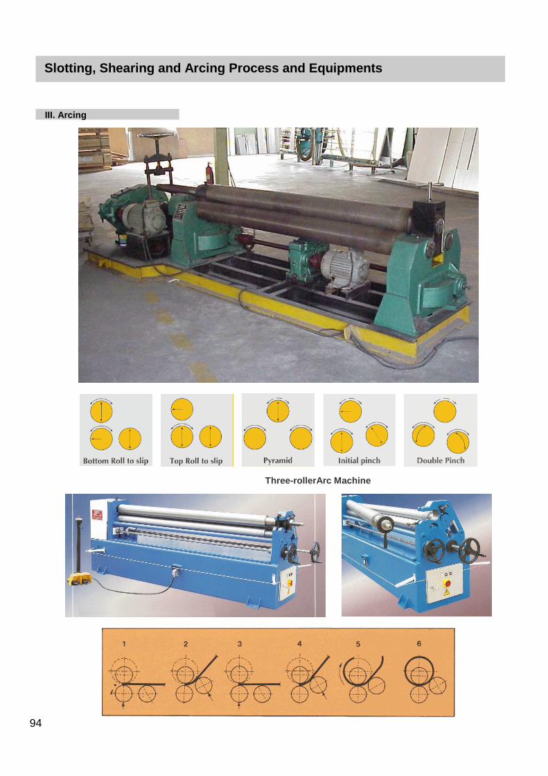
94
Slotting, Shearing and Arcing Process and Equipment s
III. Arcing
Three-rollerArc Machine

95
Hot Air Welding
Hot Air Welding

Transportation, Storage and Process Considerations
Transportation, Storage and
Process Considerations
(1) It should be prevented from installing in the abnormal environment
such as the flue dust, dust storm, radiation, noxious gas and chemicals.
(2) The products should be placed horizontally regardless during the
transportation or in the warehouse. If it is necessary to be placed
vertically, the panel should be placed vertical to the plane. The panels
should be placed compactly with each other, and the storage limit
should not exceed 6 months. When single or multiple panel materials
are transported, four sides of the panel should be raised up. Don't drag
and pull the single side of the panel.
(3) The sawing, trimming, edge cutting, riveting, slotting, bending and
lacquering can be carried out for this product.
(4) The slotting should use the flat header V-shaped cutting tools. The
width of the slotting bottom is 2.5-4mm, and the blade should be sharp,
the rotation speed is 2000-3000 rpm and the feeding speed is 3-5m/min,
to prevent from peeling of the Aluminum Composite Panels by the
melting of the bonding agent for too high temperature during the slotting.
The plastic core material with the thickness 0.2-0.4 mm should be
reserved between the lowest point of the slotting and the Al plate. The
distance between the slotting central line and the edge of the Aluminum
Composite Panels should be greater than 20 mm.
If the slotting is too shallow, it is hard for the folding process, and if the
slotting is too deep, the paint crack phenomenon will take place for the
panel surface coating after the folding process, and the whole strength
of the Aluminum Composite Panels can not be ensured. Only the
standardized slotting construction can meet the processing requirement.
(5) It is necessary to apply the force evenly during the folding for the
primary molding. Don't apply the force suddenly or bend it repeatedly. It
had better fabricate simple folding calipers for the field operation, to
ensure the requirement of the processing quality and improve the
process rate.
■
■
96
■
■
■
Transportation, Storage and Process Considerations
Transportation, Storage and
Process Considerations
(6) Don't fill in the silicone gels in rain. During injecting the silicone
gel, pay attention to prevent the bubble and the coating of the
silicone gels should be even. After the silicone gel is coated at the
seam, use the knife with the arc surface to scratch the seam into
the arc surface.
(7) For the arc surface decoration, the bending equipment should
be used for the processing, gently apply force to make the bending
of the Aluminum Composite Panels up to required curved surface,
and the curvature radius should not be less than 20cm.
(8) The installation should be carried out according to the arrow
direction. Prevent the visual color difference caused by the ray
reflection, especially for the Aluminum Composite Panels with the
metal particles.
(9) Don't remove the protective film before the construction is
completed, to prevent from scratching the surface painting film. The
protective film should be removed within 45 days after the
construction is completed.
(10) The resin or hardened glue should not be used for the
installation of the internal wall board. Otherwise, it will not be flat. It
had better take the plywood or other related materials as the floor
of Aluminum Composite Panels for the installation of the internal
wall. Don't paste the Aluminum Composite Panels in the cement
wall directly.
(11) After the folding for Aluminum Composite Panels, the channel
dimension of corresponding lining dimension should not be greater
than 600mm*600mm, to ensure the requirement of the panel
strength is met.
From the above mentioned, it is necessary to improve the field
management, pay attention to the field environmental sanitation
and carry out the standardized construction by the standard, to
meet the quality requirement and achieve the installation effect.
■
■
97
■
■
■
■

Protection and Cleaning of Curtain Walls for Alumin um Composite Panels
Protection and Cleaning of
Curtain Walls for Aluminum
Composite Panels
1. The protective measure should be taken for curtain wall
members and panels of Aluminum Composite Panels, and such
phenomena as the deformation, discoloration and pollution should
not take place.
2. The sealants on the curtain wall surface should be cleaned in
time during the curtain wall construction.
3. After the curtain wall engineering is completed, the protective
film should be removed within the specified date on the protective
film. The cleaning solution should be worked out to prevent from
damaging the surface for the cleaning.
[Description] The protective film of Aluminum Composite Panels
plays the role in preventing the panel surface from damaging during
the construction. After the construction is completed, the protective
film should be removed in time, to reduce the probability that
causes it hard to remove the protective film for the degradation,
serious sealant missing or pollution of the Aluminum Composite
Panels surface.
4. The flexible cleaning shoul be carried out for curtain walls of
Aluminum Composite Panels by the neutral cleaner without the
corrosion and pollution of the plate surface. Before the cleaning,
consult the plate manufacturers for related considerations. The
Aluminum Composite Panels should be cleaned and serviced for
one time every year at least and the surface defect and hazardous
substances should be removed, to maintain the surface clean and
ensure the normal service life of products.
[Description] The surface paint baking of Aluminum Composite
Panels should be carried out with professional cleaning and
maintenance periodically, and the hazardous filth for the paint
baking on its surface should be removed, to ensure long-term
quality of the paint baking. When the curtain wall is cleaned, it is
suggested to clean the external wall of buildings one time every
year at least. The surface cleaning should be carried out for the
indoor wall depending on the actual dirt degree.
■
98
■
■
■
Protection and Cleaning of Curtain Walls for Alumin um Composite Panels
Protection and Cleaning of
Curtain Walls for Aluminum
Composite Panels
The cleaning of the building walls should be carried out by manual
or appropriate cleaning equipment from the top to bottom. Don't
use any goods with corrosion to wipe and clean the surface of the
paint baking.
The concrete cleaning steps are shown as follows:
1. Use a large amount of clean water to rinse the surface of
panel firstly.
2. Use the soft cloth dipped with the detergent diluted by water to
wipe the surface of panel gently.
3. Then use a large amount of clean water to rinse the surface of
panel again to remove the dirt.
4. Check the surface of panel, and pay attention to clean the
place at which is not cleaned completely by the detergent.
5. Use the clean water to rinse the surface of panel until all of the
detergents are removed.
Note: Don't clean the hot surface (when the temperature exceeds
40 ¡ãC) for it is harm to the paint baking of the panel surface if the
water content is volatilized too quickly. Special attention should be
paid to select appropriate detergents. One basic principle is to
select the neutral detergents. Don't use the detergents with strong
alkali, such as potassium hydrate, sodium hydroxide or sodium
carbonate, the detergents with strong acid, the detergents with
corrosion or the detergents with soluble paint baking.
Furthermore, you had better select a small area to clean before
cleaning for a large area, and then begin the formal cleaning after it
is confirmed to be safe.
99
The Aluminum Composite Panels are the complex of the PE core
material and the dual-side aluminum panel. In general, the
aluminum material in the panel is about 50 percent of the weight for
the plate. Hence, the Aluminum Composite Panels provide superior
rigidity and light weight, and it is easy to process and install in
buildings.
For various components of Aluminum Composite Panels are the
recyclable resources, the waste material generated during the
manufacturing should be recycled fully. In general, we use the
aluminum panel heating method to carry out the separation and
recycling.
Heating Recycling Method
The waste panel generated during the manufacturing is cut into the
strip by the cutter, and the small-sized waste material may not be
cut. The side strip is placed into the heating furnace to heat up and
bake, to melt the hot-melt sealant for the bonding, and then peel
the surface aluminum and plastics. In general, the heating of
Aluminum Composite Panels takes the electric furnace or steam
heating method.
1. The recycling reprocessing will be carried out for the aluminum
panel after the separation by the aluminum processing plant.
2. The reprocessing will be carried out for the plastic core plate
after the separation. And it can be used for other aspects of the
plastic processing.
■
100
Recycling of Aluminum Composite Panels
Recycling of Aluminum
Composite Panels
■
Connection Design of Curtain Wall Components and Ma in Body Structures
Connection Design of Curtain
Wall Components and Main
Body Structures
6. If the axial force , appropriately get M-0.4NZ=0
as the boundary condition for the calculation of the shearing
bearing capacity and the stressed bending bearing capacity.
For the embedded parts that undertake the normal tensile force
and bending moment, the resistance in the tensile force item for the
anchoring bar section area calculation formula should be multiplied
by the coefficient 0.8, which is the reduced coefficient to improve
the safety margin by taking the importance of the embedded parts
and the complex of the force into account.
When the straight anchoring bar and the bending anchoring bar
take effect at the same time, take the total of shearing force
subtracting the shearing of the straight anchoring bar as the
shearing of the bending anchoring bar to calculate the section area:
Related foreign specification and domestic test research on the
bending anchoring bar in the steel and concrete combined structure
shows that the bending angle of the bending anchoring bar has not
important effect on the shearing bearing capacity. At the same time,
control the bending angle within 15°~ 45° by taking the structure
into account. When the straight anchoring bar is not set or only set
by the structure, it will not be considered in the calculation, and we
get As=0.
The basic structure of embedded parts specified here requires take
the meeting common embedded parts as the goal. The calculation
formula is also established according to the requirement of these
basic structures.
Upon calculating the anchoring area A, we suppose the anchoring
bar plays its role fully, and the stress is up to its strength design
value . To make the stress of the anchoring bar is up to and
anchoring bar doesn’t slide or remove, the anchoring length should
be enough, which is related to the model of the steel bar, the
strength of the concrete and the type of the steel. The anchoring
length can be calculated by the following formula:
76

Connection Design of Curtain Wall Components and Ma in Body Structures
Connection Design of Curtain
Wall Components and Main
Body Structures
5. For the stressed embedded parts that consist of the anchor plate
and the anchoring steel bar in the symmetric position, it can be
designed according to the regulation of JGJ133.
[Description] JGJ133 puts forward general regulation for the
embedded part design of curtain walls. The requirement for the
embedded parts mainly complies with related research outcomes
and existing national standard Code for Design of Concretes
GB50010.
1. The shearing bearing capacity of the shearing embedded parts is
related to the intensity level, the strength, the arrangement method
and diameter of steel bars.
2. For the embedded parts that suffer from the normal tensile force,
the anchoring bar undertakes both the tensile force and the internal
shearing force caused by the bending deformation of the steel plate,
to make the anchoring bar be in the combined stress status when
the steel plate bends and deforms. Hence, the reduced coefficient
of the anchoring plate bending and deformation is introduced into
the calculation formula.
3. For the embedded parts that undertake the bending moment, the
test indicates that the resultant force point at the stressed area
usually exceeds the edge bar at the stressed area. For the
convenience and safety, the bending force arm gets the distance
between the center lines of the external anchoring bars.
Furthermore, the reduced coefficient of the anchoring plate bending
and deformation is introduced into the calculation formula.
4. For the embedded parts that undertake the tensile force,
shearing force, or tensile force and bending moment, their bearing
capacities are supposed to be linear interrelated.
5. For the embedded parts that undertake the shearing force and
bending moment, when V/Vu0>0.7, the shearing bearing capacity
is linear interrelated with the bending bearing capacity, and when
V/Vu0≤0.7, the shearing bearing capacity is not interrelated with
the bending bearing capacity according to the test result. Where,
Vu0 is the shearing bearing capacity when the embedded part
undertakes the shearing action individually.
■
77

Connection Design of Curtain Wall Components and Ma in Body Structures
Connection Design of Curtain
Wall Components and Main
Body Structures
Where, is the anchoring length of the tensile steel bar (mm).
is the design value of the tensile strength for the concrete axis
center, it gets the value according to existing national standard
Code for Design of Concretes 50010. When the strength of
concretes is higher than C40, we get C40.
is the nominal diameter of anchoring bars (mm).
is the shape coefficient of anchoring bars. We get 0.16 for the
round steel bar and 0.14 for the steel bar with ribs.
Sometimes, it is hard to use curtain wall embedded parts for the
value is too large. Hence, we use the low stress design method,
namely, increase the area of the anchoring bar and reduce the
actual stress of the anchoring bar, to shorten the anchoring length.
However, the anchoring length should not be less than 15 times of
the steel bar diameter.
6. The embedded steel plate of the slotted embedded parts and
other connection measures should be designed according to
related regulation of existing national standard Code for Design of
Steel Structures GB50017.
7. The anchor bolt connection for curtain walls frame and main
body structure should comply with the following regulation:
1 The products should be equipped with the leave-factory
certificate.
2 The anti-corrosion processing should be carried out for the
anchoring bolt of the carbon steel.
3 The field test of the bearing capacity should be carried out, and
the pull-out test should be carried out, if required.
4 Each connection node should not be equipped with the anchor
bolts less than 2.
5 The diameter of anchor bolts should be determined by the
calculation of the bearing capacity and should not be less than
10mm.
6 The welding operation should not be carried out on the
connector that contacts with the chemical anchor bolts.
7 The design value of the bearing capacity for anchor bolts
should not be greater than 50 percent of its limit bearing capacity.
[Description] If no embedded part is set and the embedded part is
missed in civil engineering, or the embedded part offsets the design
position too
■
■
78

Connection Design of Curtain Wall Components and Ma in Body Structures
Connection Design of Curtain
Wall Components and Main
Body Structures
much, or the design is changed, or the old building is added with
curtain walls, it is usually necessary to be connected by the post
anchor bolt. When the post anchor bolt (mechanical or chemical
anchor bolt) is used, several measures should be taken to ensure
the reliability of connection.
8. When curtain walls are connected with the masonry structure,
the steel bar concrete or steel structural beam and column should
be set on the main body structure of connection parts. The light
filling wall should not be taken as the supporting structure of curtain
walls.
[Description] The bearing capacity outside of the masonry structure
plane is low and it is hard to be connected directly. Hence, the
concrete structure or steel structure connection component should
be added. The bearing capacity and deformation capacity of the
light partition wall is low and should not be taken as the supporting
structure of curtain walls.
■
79

Endurance and Safety Performance
Endurance and Safety
Performance
1. The color of the paint baking for Aluminum Composite Panels is
allowed to change with the time, and it will show slight and even
change in the same facade. However, the long term performance
test should be carried out according to the nation standard of the
fluorocarbon paint and customers should be provided with 10 years
or more quality assurance (For the details on the test method and
index requirement, refer to the clause 3.2.3 in athis specification).
[Description] The surface endurance performance of curtain walls
for Aluminum Composite Panels mainly depends on the color of
products, the use location, environment and direction. The variation
of effect factors causes the slight difference of the degradation
speed of curtain wall panels. However, the degradation condition
should be same under the same factor, and the change condition
(such as fading) should be even.
2. The fireproof design of curtain walls for Aluminum Composite
Panels should comply with related regulation of existing national
standard Code of Design on Building Fire Protection and
Prevention GB50016, and the curtain wall fireproof of tall buildings
should comply with related regulation of existing national standard
Code for Fire Protection Design of Tall Buildings GB 50045.
[Description] The curtain wall fireproof of Aluminum Composite
Panels is not specified in the Code of Design on Building Fire
Protection and Prevention GB 50016 definitely. However, it puts
forward some fireproof regulation for the building material and
different parts of the building. When curtain walls are in these parts,
related requirement should be met.
It specified the building curtain wall in the Code for Fire Protection
Design of Tall Buildings GB 50045 definitely, and it should be
complied with.
3. The fireproof sealing design should be designed for the seam
between the curtain wall and surrounding fireproof partition
members, the seam between the curtain wall panel or partition wall
outer space and the seam between the real wall surface opening
edges.
[Description] Although curtain walls of Aluminum Composite Panels
themselves don’t provide special fireproof capacity, it is a part of
the whole building as the external envelope structure. Some
important parts should provide a certain fire resistance, and comply
with the whole fireproof requirement of the building.
■
■
■
80

Endurance and Safety Performance
Endurance and Safety
PerformanceThe fireproof sealing is a fire protection and smoke isolated method
with broad application for current building design, which is formed
by filling the material that is not inflammable or fire resistant in the
seam, to reach the goal that prevents the flame and high
temperature flue gas and noxious gas from spreading in buildings.
4. The smoke protection and fireproof sealing structural system of
curtain walls should provide the sealing and endurance. If it
catches fire, the integrity should be maintained within the specified
fire resistance limit.
[Description] The endurance, adaptable capacity of the deformation
and stability is the basic requirement of the fireproof sealing
material or system, which should be integrated considered and
rationally selected according to the width amd property of the seam
(for example, whether the extension/contraction deformation takes
place), material quality of adjacent members, other surrounding
environment factors and design requirements. In general, the larger
of the seam, the larger of the extension/contraction and the higher
the fireproof level, the higher the requirement of the fireproof
sealing material or system is.
5. The fireproof sealing system should use the non-inflammable or
fire retardant material that complies with the requirement.
[Description] The fireproof sealing structural system of curtain walls
provides several effective fabrication methods. Regardless of any
methods, the material made of the system should provide the fire
resistance performance specified in the design.
6. The seam between the curtain wall and floor slab compartment
can use the rock wool or mineral wool sealing. The thickness of the
rock wool and mineral wool should not be less than 100mm, and
should be filled tightly. The thickness of the rock wool and mineral
wool between the floors should use the zinc coated steel sheet with
the thickness no less than 1,5mm, and the seam between the
bearing board and other structures should be filled with the
fireproof sealing material.
[Description] The bearing board of the fireproof sealing should use
the anti-corrosive processing steel plate with the thickness no less
than 1.5mm, but not use the single aluminum plate or Aluminum
Composite Panels.
■
■
■
81

Endurance and Safety Performance
Endurance and Safety
Performance
7. The lightning protection design of curtain walls for Aluminum
Composite Panels should comply with related regulation of existing
national standard Code for Protection of Structures against
Lightning GB 50057 and Code for Electrical Design of Civil
Buildings JGJ/T 16. The member as the lightning protection
network in the metal frame of curtain walls should be connected
with the lightning protection system of the main body structure
reliably. For the building with the requirement of the
electromagnetic shield or using the common grounding protection,
the lightning design of its curtain walls should comply with related
requirement of Protection against Lightning Electromagnetic
Impulse - Part 1: General principles GB/T 19271.1.
[Description] Existing national standard Code for Protection of
Structures against Lightning GB 50057 doesn’t put forward the
regulation on the curtain wall lightning protection concretely and
definitely.
The curtain wall of Aluminum Composite Panels is the envelope
structure that is attached to the main building. The metal frame of
curtain walls is usually not taken as the lightning protection
grounding, but makes use of the lightning protection system of the
main body structure and combines with the lightning protection
design of the building itself. Hence, it is required to be connected
with the lightning protection system of the main body structure
reliably, and keep the conduction smooth.
In general, the column of curtain walls should use the flexible cable
to connect with each other. For the floor whose main building has
the horizontal grading ring, the embedded parts or fittings of the
column should use the circular steel or flat steel to connect with the
horizontal grading ring welding, to form the conduction path. The
welding seam and the connection cable should be coated with the
antirust paint. The section area of the flat steel should not be less
than 5mm×40mm, and the diameter of the circular steel should not
be less than 12mm.
The curtain wall key roof stratum with the lightning protection
function should be made by using the aluminum alloy plate with the
thickness no less than 3mm, the section area of the key roof
stratum should not be too small. The curtain wall key roof stratum
system should be effectively connected with the lightning protection
system of the main body structure roof.
82

Endurance and Safety Performance
Endurance and Safety
PerformanceFor the building with the electromagnetic protection requirement,
the Protection against Lightning Electromagnetic Impulse - Part 1:
General principles GB/T 19271.1 requires the metal members with
large size, such as the metal window, carry out the equi-potential
connection with the lightning protection system (LPS), and the
protection network formed by the metal member should not be too
large. For the equi-potential connection, this standard puts forward
a certain requirement that should be met for the lightning protection
design of curtain walls.
8. For the endurance of curtain walls for open Aluminum Composite
Panels, in addition to above-mentioned whole endurance
performance, it should be noted to take the long-term surface
treatment quality, the matching with the surface paint baking of
Aluminum Composite Panels and preventing the rust from affecting
the performance into account. Furthermore, it should also be noted
to consider the endurance of the internal fixation for the curtain
walls, connection and installation of assistant fittings. If the
surrounding environment of buildings is special, such as the
seaside and corrosive air (such as the building within the industrial
pollution area), it is necessary to use the material with superior
endurance.
■
83

Relationship between Bending Deflection and Panel D imension (Setting of Reinforced Rib) of Aluminum Composite Panels for Cu rtain Walls
Relationship between
Bending Deflection and
Panel Dimension
(Setting of Reinforced
Rib) of Aluminum
Composite Panels for
Curtain Walls
Wind Load Mpa Allowed Panel Length (mm) Center Deflection (mm) Rivet Hole Distance (mm)
Width of Panel: 1000mm:
500 8000 26 500
600 8000 32 500
700 8000 37 500
800 3700 37 500
900 3300 35 500
1000 3000 34 500
1100 2700 33 500
1200 2400 31 500
1400 2100 30 500
1600 1700 25 500
1800 1400 22 500
2000 1200 20 500
2200 1100 18 500
2400 1000 17 500
2600 900 16 500
2800 800 15 400
3000 750 15 400
500 3800 35 500
600 3300 38 500
700 3000 38 500
800 2800 37 500
900 2500 36 500
1000 2300 35 500
1100 2000 31 500
1200 1800 28 500
1400 1500 25 500
1600 1300 23 500
1800 1100 21 500
2000 1000 20 500
2200 900 19 500
2400 800 18 400
2600 750 18 400
2800 700 17 300
3000 650 16 30084
Width of Panel: 1250mm

Relationship between Bending Deflection and Panel D imension (Setting of Reinforced Rib) of Aluminum Composite Panels for Cu rtain Walls
Relationship between
Bending Deflection and
Panel Dimension
(Setting of Reinforced
Rib) of Aluminum
Composite Panels for
Curtain Walls
Wind Load Mpa Allowed Panel Length (mm) Center Deflection (mm) Rivet Hole Distance (mm)
Width of Panel: 1500mm:
500 3400 43 500
600 3000 42 500
700 2700 41 500
800 2300 36 500
900 2000 32 500
1000 1800 30 500
1100 1600 28 500
1200 1500 27 500
1400 1250 25 500
1600 1100 24 500
1800 1000 23 500
2000 900 22 400
2200 800 21 400
2400 750 20 300
2600 700 19 300
2800 350 18 300
3000 600 15 300
Above data is obtained on the basis of the following data:
1. The allowed design stress of the surface aluminum composite panel is
51MPa (evaluate 2.5 times of safety factors for the failure and 1.75 times
of the permanent deformation).
2. The EI equivalent rigidity value of the panel is 0.24kNm2m-1.
3. The allowed design strength of rivets (the safety factor is 3) is the
shearing strength Rc=720N and tensile strength Rt=680N.
4. The interaction between the shear and tensile stress is given as
Fc/Rc+Ft/Rt《1, where, Fc and Ft are the application load of the shear
and tensile respectively.
5. The fixing space is the diameter of the drilling hole subtracting the
diameter of rivets, which is equal to 0.3mm.
6. The allowed frame deformation is less than 1/200 of the vertical spans
between wall frames.
85