althykex* excitation system 3s7931sa412 - 416 series ... · 3s7931sa412 - 416 series ... by...
TRANSCRIPT
GEK-36430
INSTRUCTIONS
ALTHYkEX* EXCITATION SYSTEM
3S7931SA412 - 416 SERIES
3S7931SA420 - 424 SERIES I - i I 1
. i I r
GENERAL ELECTRIC AUGUST, 1973
*Trademark of General Electric Co., USA
GEK-36430
TABLE OF CONTENTS Page No.
INTRODUCTION ................................................................ 3
RECEIVING, HANDLING AND STORAGE .......................................... 3
DESCRIPTION ..................................................................
INSTALLATION ................................................................ Location and Mounting ..................................................... Connections ...............................................................
INITIAL OPERATION ........................................................... Preliminary Checks ........................................................ Settings Before Operating Generator .......................................... Off Line Tests, Generator Running .......................................... Exciter AC Regulator Stabilizing ........................................... Generator AC Regulator Stabilizing .......................................... On-Line Tests, Generator Running .......................................... Under-excited Reactive Ampere Limit Adjustment ............................. Current Limit Adjustment ................................................... Fault Suppression Adjustment ................................................ Maximum Excitation Limit Adjustment ......................................
3
4 4 5
5 5 5 7 7 8 9
i 10 10
OPERATION .................................................................... Preliminary Checks ....................................................... Operating Sequence .......................................................
10 10 11
PRINCIPLES OF OPERATION .................................................... Exciter Field Bridge ......................................................
Thyristor Bridge Circuit .............................................. Diode Rectifier Circuit - Current Boost .................................
Generator Field Thyristor Bridge ........................................... Firing Circuit ............................................................
Master Firing Circuit ................................................ Trigger Circuit .....................................................
Generator AC Voltage Regulator ............................................. Phase Back Limit ....................................................
Exciter Voltage Regulators .................................................. DC Voltage Regulator (Manual) ............................................... Maximum Excitation Limit ................................................ Under-Frequency Limit .................................................... Maximum Current Limit ................................................... Fault Suppression Circuit ................................................. Reactive Current Compensator (RCC) ........................................ Active-Reactive Current Compensator (ARCC) ................................ Under-Excited Reactive Ampere Limit (U. R. A. L. ) ........................... Power System Stabilizer .................................................... Relay and Control Circuit .................................................. Sequence of Operations .................................................... Miscellaneous Functions ....................................................
MAINTENANCE ................................................................ Procedure for Installing SCRs ...............................................
11 14 14 16 19 19 20 23 24 28 28 28 30 30 30 30 30 33 33 33 33
i”6
TROUBLESHOOTING ............................................................
36 36
37
RENEWAL PARTS ............................................................. 37
These instrucfrons do not purport fo cover o/l defoils or variations in equipment nor to provide for every possible confingency fo be met m connection with insfdofion, operafwn or maintenance Should further information be desired or houkf purficukr problems orrse whkh ore not covered sufficrenfly for the purchaser’s purposes, fhe moffer should be referred fo Geneml Elecfric Company
2

GEK- 36430
ALTHYREX EXCITATION SYSTEM
INTRODUCTION This Excitation System controls the voltage (or re- active volt-amperes) of an AC generator by control- ling its excitation. This system uses a smaller AC generator as a power source for excitation. The AC voltage from this smaller AC generator is controlled by parallel banks of the thyristors (SCRs) to furnish DC current for the main generator field. For clarity, the small AC generator will be called the Exciter and the larger AC generator will be called the Generator.
The exciter terminal voltage, or generator excitation source voltage, is maintained at a constant value by a static voltage regulator. A portion of the exciter output is fed back to a thyristor bridge to supply ex- citer field current excitation. The exciter field cur- rent is varied by controlling the exciter thyristor bridge output by a static voltage regulator, The ex- citer regulator automatically maintains a constant voltage at the exciter terminals.
The generator field current is also varied by control- ling the generator thyristor bridge output by a static voltage regulator. The generator regulator includes both Auto and Manual control functions to regulate generator terminal voltage or generator field voltage respectively.
This Excitation System is completely static, with the exception of the exciter, which is a small AC genera- tor. No moving parts or vacuum tubes are used to perform the regulating function. Relays are used only for start-up, changing mode of operation, and protective functions. The regulator voltage adjustor potentiometer may be motor driven in some installa- tions. The system may also include various limit circuits, compensator circuits, start-up circuits, and relaying.
RECEIVING, HANDLING AND STORAGE RECEIVING AND HANDLING
Immediately upon receipt, the equipment should be carefully unpacked to avoid damage. Particular care should be exercised to prevent small parts from being mislaid or thrown away in the packing material.
As soon as the equipment is unpacked, it should be examined for any damage that might have been sus- tained in transit. If injury or rough handling is evident, a damage claim should be filed immediately with the transportation company and the nearest General Electric Sales Office should be notified promptly.
STORAGE
If the equipment is not to be used as soon as it is un- packed, it should be stored in a clean, dry place and protected from accidental damage. Particular care should be exercised to avoid storing the equipment in locations where construction work is in progress. If the equipment is to be stored for more than three months, it should be kept heated to at least 5°C above ambient temperature to keep out moisture.
DESCRIPTION
The 3S7931SA412 and 3S7931SA420 are exciter regu- lator cubicles furnished with tandem compound tur- bine generators and may include the following:
1 337932CD147
1 3S7932CD148
1 3S7932FA106
2 3S7932FA107
1 44C318148
2 3S7932JAlll
1 3S7932JA112
1 3S7932LA202
1 357932MA265
2 397932MA268
1 387932MA280
2 3S7932MA282
1 357932MA283
1 357932MA284
1 3S7932MA285
1 3S7932MA3 18
1 3S7932MD200
2 357932MD125
Control Panel
Protective Panel
Disconnect Panel
Fuse Panel
Exciter Master Firing Power Circuit
Volts per Hertz Regulator
Maximum Excitation Limit Panel
Power System Stabilizer
Volts per Hertz Protection Panel
AC Voltage Regulator
Exciter Master Firing Panel
Resistor Panel
Filter Panel
Potential Transformer Panel
Test Panel
AC Voltage Regulator Failure Alarm
Meter Panel
Shaft Voltage Suppressor Panel
Althyrex Excitation System GEK-36430
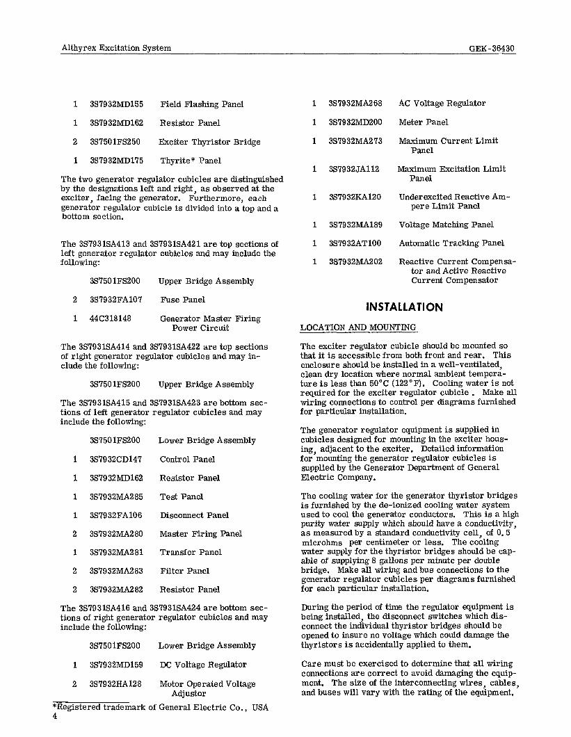
1 3S7932MD155 Field Flashing Panel
1 3S7932MD162 Resistor Panel
2 3S7501FS250 Exciter Thyristor Bridge
1 387932MD175 Thyrite* Panel
The two generator regulator cubicles are distinguished by the designations left and right, as observed at the exciter, facing the generator. Furthermore, each generator regulator cubicle is divided into a top and a bottom section.
The 3S7931SA413 and 3S7931SA421 are top sections of left generator regulator cubicles and may include the following :
3S7501FS200 Upper Bridge Assembly
2 3S7932FA107 Fuse Panel
1 44C318148 Generator Master Firing Power Circuit
The 3S7931SA414 and 3S7931SA422 are top sections of right generator regulator cubicles and may in- clude the following:
3S7501FS200 Upper Bridge Assembly
The 3S7931SA415 and 3S7931SA423 are bottom sec- tions of left generator regulator cubicles and may include the following:
3S7501FS200 Lower Bridge Assembly
1 3S7932CD147 Control Panel
1 387932MD162 Resistor Panel
1 3579 32MA2 85 Test Panel
1 3S7932FA106 Disconnect Panel
2 387932MA280 Master Firing Panel
1 357932MA281 Transfer Panel
2 357932MA283 Filter Panel
2 3S7932MA282 Resistor Panel
The 3S7931SA416 and 357931SA424 are bottom sec- tions of right generator regulator cubicles and may include the following:
3S7501FS200 Lower Bridge Assembly
1 3S7932MD159 DC Voltage Regulator
2 3S7932HA128 Motor Operated Voltage Adjustor
*Registered trademark of General Electric Co., USA 4
1 3S7932MA268
1 3S7932MD200
1 3S7932MA273
1 3S7932JA112
1 387932KA120
1 3S7932MA189
1 3S7932ATlOO
1 3S7932MA202
AC Voltage Regulator
Meter Panel
Maximum Current Limit Panel
Maximum Excitation Limit Panel
Under excited Reactive Am- pere Limit Panel
Voltage Matching Panel
Automatic Tracking Panel
Reactive Current Compensa- tor and Active Reactive Current Compensator
INSTALLATION
LOCATION AND MOUNTING
The exciter regulator cubicle should be mounted so that it is accessible from both front and rear. This enclosure should be installed in a well-ventilated, clean dry location where normal ambient tempera- ture is less than 50°C (122°F). Cooling water is not required for the exciter regulator cubicle . Make all wiring connections to control per diagrams furnished for particular installation.
The generator regulator equipment is supplied in cubicles designed for mounting in the exciter hous- ing, adjacent to the exciter. Detailed information for mounting the generator regulator cubicles is supplied by the Generator Department of General Electric Company.
The cooling water for the generator thyristor bridges is furnished by the de-ionized cooling water system used to cool the generator conductors, This is a high purity water supply which should have a conductivity, as measured by a standard conductivity cell, of 0.5 microhms per centimeter or less. The cooling water supply for the thyristor bridges should be cap- able of supplying 8 gallons per minute per double bridge. Make all wiring and bus connections to the generator regulator cubicles per diagrams furnished for each particular installation.
During the period of time the regulator equipment is being installed, the disconnect switches which dis- connect the individual thyristor bridges should be opened to insure no voltage which could damage the thyristors is accidentally applied to them.
Care must be exercised to determine that all wiring connections are correct to avoid damaging the equip- ment. The size of the interconnecting wires, cables, and buses will vary with the rating of the equipment.

Althvrex Excitation System GEK-36430
CONNECTIONS
1. Wire check all external connections to all regulator equipmen%ubicles.
2. Check CT and PT polarities (on generator out- put) connecting to the generator regulator. RCC current transformer must be in proper phase. The PT burden is approximately 300 VA maximum total. The CT burden is approximately 500 VA maximum.
3. Check all connections from the BR terminal board in the exciter regulator cubicle to 4CT, 5CT, 6CT, and the exciter armature output.
4. Check generator and exciter phase sequence.
5. Check all clamp on type thyristors with ohm- meter (in exciter and generator field circuits).
6. Check all thyristor gate leads for connection to the proper trigger circuits.
7. Check all trigger circuit disconnect plugs for connection.
8. Check wire size of interconnecting wiring per diagram furnished with control.
ALL THYRISTOR HEAT SINKS ARE AT “ABOVE GROUND” POTENTIAL. ANY WIRING OR CIRCUITS TO BE HI-POTTED MUST FIRST BE DISCONNECTED FROM THE REGULATOR CUBICLES. DO NOT HI-POT ANY CIRCUITS IN CONTROL OR THYRISTOR CUBICLE.
INITIAL OPERATION
All controls have been preset at the factory. If any of the calibration procedures described below are not performed following installation, the factory sting of the pertinent control should be retained. The factory setting should be recorded in Figure 1 for future reference.
Except in unusual operating circumstances, the factory setting should agree with that obtained in the calibration procedures described below,
PRELIMINARY CHECKS
The following steps must be performed before run- ning the generator or exciter:
a. Energize DC for relay power. Check polarity.
b. Check operation of exciter field breaker.
c.
d.
e.
f.
!&
h.
1.
J.
Check operation of motor operated voltage adjustors -- generator manual control and auto control.
Check operation of 43CS switch and all asso- ciated relays. (See Principles of Operation -- Relay and Control Circuit.)
Check that flashing circuit will apply DC to exciter field circuit.
Check operation of all protective relays.
Check field ground detecting relays.
Check operation of over-temperature circuits (lights, relays, and alarms).
If ventilation fans are provided, check fan operation and air flow alarm circuit.
Perform dummy load tests on all exciter and generator thyristor bridges.
SETTINGS BEFORE OPERATING GENERATOR
a.
b.
c.
d.
e.
f.
is
Turn water flow ON for generator thyristor bridges. Open generator field thyristor bridge disconnect switches.
Turn exciter cubicle ventilation fans ON. Close exciter field thyristor bridge disconnect switches.
Set exciter auto voltage adjustor (Alp) fully CCW. Set A2P VOLTAGE RANGE at mid- point. Set A3P VOLTAGE LEVEL fully CCW. Set A4P GAIN at midpoint. Set A5P STABlLIZ- ING at midpoint. On terminal board 2TB, use metal jumpers supplied to jumper terminals B-C, D-E, and G-H. Set A6P PHASE BACK LIMIT fully CW. Set generator auto voltage adjustor (A201P) fully CCW (full lower if motorized). Set A204P VOLTAGE RANGE at midpoint. Set A205P VOLT- AGE LEVEL fully CCW. Set A203P GAIN fully CCW (minimum gain). Set A202PSTABILIZING at midpoint. On terminal board 2TB, use metal jumpers suppliedto jumper terminals B-C, D-E, and G-H. Set A206P PHASE BACK LIMIT fully cw. Set generator manual control voltage adjustor (D2OlP) in full LOWER position. Adjust regulator pre-position limit switches LS5 and I LS6 as required. Set D262P fully CCW.
Leave all other adjustments per factory setting.
Disconnect and isolate lead to terminal Bll, output of U. R. A. L. panel.
Althyrex Excitation System GEK-36430
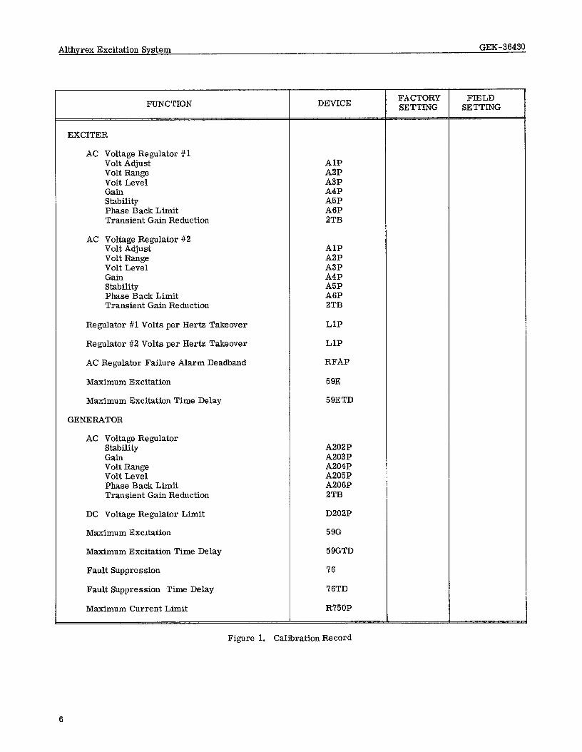
FUNCTION
EXCITER
AC Voltage Regulator #l Volt Adjust Volt Range Volt Level Gain Stability Phase Back Limit Transient Gain Reduction
AC Voltage Regulator #2 Volt Adjust Volt Range Volt Level Gain Stability Phase Back Limit Transient Gain Reduction
Regulator #l Volts per Hertz Takeover
Regulator #2 Volts per Hertz Takeover
AC Regulator Failure Alarm Deadband
Maximum Excitation
Maximum Excitation Time Delay
GENERATOR
AC Voltage Regulator Stability Gain Volt Range Volt Level Phase Back Limit Transient Gain Reduction
DC Voltage Regulator Limit
Maximum Excitation
Maximum Excitation Time Delay
Fault Suppression
Fault Suppression Time Delay
Maximum Current Limit
DEVICE
AlP A2P A3P A4P A5P A6P 2TB
AlP A2P A3P A4P A5P A6P 2TB
LlP
LlP
RFAP
59E
59ETD
A202P A203P A204P A205P A206P 2TB
D202P
59G
59GTD
76
76TD
R750P
FACTORY SETTING
FIELD SETTING
Figure 1. Calibration Record

Althyrex Excitation System GEK-36430
h. Apply all auxiliary power to excitation system; DC relay power, and all AC power for lights, relays, etc.
OFF LINE TESTS, GENERATOR RUNNING
a.
b.
C.
d.
e.
f.
g.
h.
Set 43CS to MANUAL position.
Set excitation control to START. 1.
Close exciter field breaker. Exciter voltage should build up to a voltage proportional to the generator speed (if below rated speed).
Set excitation control to MANUAL. Operating exciter AC regulator RAISE-LOWER CONTROL (70E) should raise and lower exciter output voltage. Be careful not to exceed an output voltage of 1.0 per unit volts/hertz below rated speed.
m. Before synchronizing the generator with the system, record all potentiometer settings for future reference,
EXCITER AC REGULATOR STABlLIZING
The exciter thyristor bridge output can be monitored by connecting an oscilloscope across the exciter field voltmeter. All six thyristors should fire as shown in Figure 4. There should be no jitter or instability.
a.
Operate 43PB to transfer from DC to AC reg- ulator. The voltage range can be adjusted using A2P and the level can be adjusted using A3P. If stabilizing is required, see Exciter AC Regulator Stabilizing. b.
Set excitation control to STOP and close all generator thyristor bridge disconnect switches.
C. Set excitation control to START. Close ex- citer field breaker. Exciter terminal voltage and generator terminal voltage should build up to a low value, or a value proportional to speed if not at rated speed.
d. If the exciter fails to maintain voltage after field flashing, increase the exciter setting, Care should be taken not to exceed an output voltage of 1.0 per unit volts/hertz below rated speed on the generator or exciter.
e.
With the excitation control set to MANUAL, the generator DC voltage I: egulator RAISE-LOWER control should raise and lower the generator field voltage.
f.
At rated speed only, the generator can be transferred to the generator AC regulator. With the generator at rated terminal voltage and the excitation control in TEST, zero the 2VM transfer voltmeter by using the generator AC regulator RAISE -LOWER control. It should be possible to obtain a meter deflection to either side of zero. If the meter deflection cannot be obtained, adjust A204P, A205P, and A203P. Do not attempt initial transfer with 2VM at a meter reading other than zero.
k. Setting the excitation control to AUTO transfers the generator from the DC to the AC regulator. The generator and the exciter voltage should remain as before. The voltage range can be adjusted using A204P and the level can be ad- justed using A205P. If stabilizing is required, see Generator AC Regulator Stabilizing.
To transfer back to manual control, zero the 2VM transfer voltmeter using the generator DC regulator RAISE-LOWER control. Setting the excitation control to either TEST or MANUAL transfers control from the AC regulator to the DC regulator.
Set A2P VOLTAGE RANGE fully CW for maxi- mum voltage range adjustment. Set A3P VOLTAGE LEVEL fully CCW for minimum voltage level. Set A4P GAIN at midpoint. Re- sistor A18R on amplifier board should not be shorted. On terminal board 2TB, use metal jumpers supplied to jumper termmals B-C, D-E, and G-H. Set A5P STABILIZING at mid- point.
Connect a normally open (NO) pushbutton or switch across potentiometer A3P VOLTAGE LEVEL.
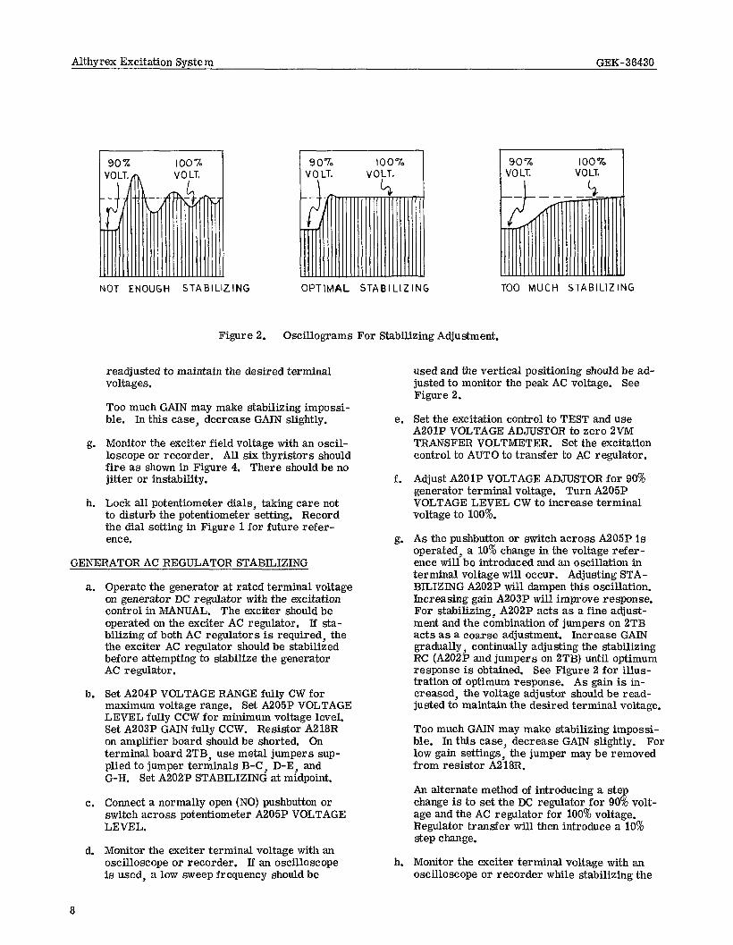
Monitor the exciter terminal voltage with an osciIloscope or recorder. If an oscilloscope is used, a low sweep frequency should be used and the vertical positioning should be adjusted to monitor the peak AC voltage. See Figure 2.
Set 43CS and use AlP VOLTAGE ADJUSTOR to zero 1OVM TRANSFER VOLTMETER. Operate 43PB to transfer to AC regulator.
Adjust AlP VOLTAGE ADJUSTOR for 90% ex- citer terminal voltage. Turn A3P VOLTAGE LEVEL CW to increase terminal voltage to 100%.
As the pushbutton or switch across A3P is operated, a 10% change in the voltage refer- ence will be introduced and an oscillation in terminal voltage will occur. Adjusting STA- BILIZING A5P will dampen this oscillation. IncreasingGAINA4P will improve response. For stabilizing, A5P acts as a fine adjustment and the combination of jumpers on 2TB acts as a coarse adjustment. Increase GAIN gradual- ly, continually adjusting the stabilizing RC (A5P and jumpers on 2TB) until optimum res- ponse is obtained. See Figure 2 for illustra- tion of optimum response. As gain is in- i creased, the voltage adjustor should be
7
Althyrex Excitation System GEK-36430
90% 100% VOLT.
\ vO\T.
90% 100% VOLT. VOLT
NOT ENOUGH STABILIZING OPTlMAL STABILIZING TOO MUCH STABILIZING
Figure 2. Oscillograms For Stabilizing Adjustment.
readjusted to maintain the desired terminal voltages.
Too much GAIN may make stabilizing impossi- ble. In this case, decrease GAIN slightly.
g. Monitor the exciter field voltage with an oscil- loscope or recorder. All six thyristor s should fire as shown in Figure 4. There should be no jitter or instability.
h. Lock all potentiometer dials, taking care not to disturb the potentiometer setting. Record the dial setting in Figure 1 for future refer- ence.
GENERATOR AC REGULATOR STABILIZING
a. Operate the generator at rated terminal voltage on generator DC regulator with the excitation control in MANUAL. The exciter should be operated on the exciter AC regulator, If sta- bilizing of both AC regulators is required, the the exciter AC regulator should be stabilized before attempting to stabilize the generator AC regulator .
b. Set A204P VOLTAGE RANGE fully CW for maximum voltage range. Set A205P VOLTAGE LEVEL fully CCW for minimum voltage level. Set A203P GAIN fully CCW. Resistor A218R on amplifier board should be shorted. On terminal board 2TB, use metal jumpers sup- plied to jumper terminals B-C, D-E, and G-H, Set A202P STABILIZING at midpoint.
c. Connect a normally open (NO) pushbutton or switch across potentiometer A205P VOLTAGE LEVEL.
d. Monitor the exciter terminal voltage with an oscilloscope or recorder. If an oscilloscope is used, a low sweep frequency should be
8
used and the vertical positioning should be ad- justed to monitor the peak AC voltage. See Figure 2.
e. Set the excitation control to TEST and use A201P VOLTAGE ADJUSTOR to zero 2VM TRANSFER VOLTMETER. Set the excitation control to AUTO to transfer to AC regulator.
f. Adjust A201P VOLTAGE ADJUSTOR for 90% generator terminal voltage. Turn A205P VOLTAGE LEVEL CW to increase terminal voltage to 100%.
g. As the pushbutton or switch across A205P is operated, a 10% change in the voltage refer- ence will be introduced and an oscillation in terminal voltage will occur. Adjusting STA- BILIZING A202P will dampen this oscillation. Increasing gain A203P will improve response. For stabilizing, A202P acts as a fine adjust- ment and the combination of jumpers on 2TB acts as a coarse adjustment. Increase GAIN gradually, continually adjusting the stabilizing RC (A202P and jumpers on 2TB) until optimum response is obtained, See Figure 2 for illus- tration of optimum response. As gain is in- creased, the voltage adjustor should be read- justed to maintain the desired terminal voltage.
Too much GAIN may make stabilizing impossi- ble. In this case, decrease GAIN slightly. For low gain settings, the jumper may be removed from resistor A218R.
An alternate method of introducing a step change is to set the DC regulator for 90% volt- age and the AC regulator for 100% voltage. Regulator transfer will then introduce a 10% step change.
h. Monitor the exciter terminal voltage with an oscilloscope or recorder while stabilizing the

Althyrex Excitation System GEK-36436
generator AC regulator, When a step change is introduced in the generator voltage, the exciter voltage should respond without instability. The main thyristor bridge firing will appear as com- mutation notches in the exciter terminal voltage. All six thyristor bridge legs should fire without jitter or instability.
i. Lock all potentiometer dials, taking care not to disturb the potentiometer setting. Record the dial setting in Figure 1 for future reference.
ON-LINE TESTS, GENERATOR RUNNING
a.
b.
C.
d.
e.
f.
With generator operating on TEST and synchro- nized with system, pick up as much as 10% load if possible.
Raise MANUAL control (D2OlP) to cause gen- erator to supply 5 or 10% of its rating as VARs (over-excited).
Set reactive current compensator (RCC) and active-reactive current compensator (ARCC) settings on zero (GlSW and G2SW).
Zero 2VM TRANSFER VOLTMETER using AC regulator voltage adjustor.
Turn GPSW COURSE on RCC to “5”. VM volt- age (AC regulator output) should decrease. If reading increases, short BlCT (generator current transformer) by opening CT switch at terminals 38-25 and 35-26, and reverse the wires to the compensator.
MAKE SURE THE PROPER TYPE OF SWITCH HAS BEEN SUPPLIED BE- FORE OPENING IT, IT SHOULD SHORT THE INCOMING TERMINALS BEFORE OPENING THE OUTGOING TERMINALS.
Final adjustment of the compensator can be made only after considerable experience with the generator operating under control of the regulator. It is desirable to keep the amount of compensation to the minimum required for proper division of VARs between generators to avoid excessive voltage regulation. As an initial adjustment, it is advisable to turn the fine-adjustment knob to position 5 with the coarse knob at zero., Adjustments may be made with the compensator current transfer - mer energized (CT switch closed).
Turn G2SW COURSE on ARCC to “5”. VM voltage (AC regulator output) should increase, If reading decreases, short BlCT (generator current transformer) by opening CT switch at
terminals 38-25 and 38-26 and reverse R and X on ARCC by reversing leads to terminals G x R and G x X. Return the reactance-adjusting knob to zero, and turn the resistance-adjusting knob, GlRH, to the right to increase resis- tance; this should also increase the AlVM volt- age.
Final adjustment of the compensator must be made on the basis of experience. Preliminary adjustment may be made in accordance with the known values of resistance and reactance for that portion of the system over which compensa- tion is desired. If the voltage at the point which is to be compensated decreases as the power factor becomes more lagging and increases as the power factor becomes less lagging, more reactance and possibly less resistance may be required.
Return generator excitation to desired VARs and zero the transfer voltmeter with the AC regulator voltage adjustor. Transfer to AC regulator by setting the excitation control to AUTO. Generator VARs should not change. The generator AC regulator should now control generator excitation and VAR output.
UNDER-EXCITED REACTIVE AMPERE LIMIT ADJUSTMENT
After satisfactory operation of the AC (AUTO) regu- lator has been obtained. the under-excited reactive ampere limit should be tested. Return the U. R. A. L. to service bv turning the URAL GAIN potentiometer to “0” (fully”CCW) aid reconnect the lead to terminal Bll. See separate instructions GEK-4’716 for adjust- ing the U. R. A. L. panel.
CURRENT LIMIT ADJUSTMENT
a. Operate generator on MANUAL control.
b. To set CURRENT LIMIT, first check calibra- tion of current limit circuit. Read generator field current at no load. Read voltage across R’75OC (terminals CL-7 and CL-8) at no load. Calculate calibration of current limit feedback circuit as follows:
K = ECL7-8 (NL) Volts ‘FLD (NL) Amp
c. Calculate generator field current limit ICL:
ICL = 1.6 x E Gen Rated Fld Volts Resistance at Gen Fld 125°C
d. Open current limit CT feedback switch at terminals 38-22, 23, 24. Connect a variable DC power supply (O-ZOO V DC) across termi- nals CL-7 and CL-8 (be sure to connect the
9

Althyrex Excitation System GEK-36430
positive side to terminal CL-7) and set for the following voltage:
ECL = KxICL
e. With this voltage across R’750C, set the excita- tion control to TEST, and zero the transfer voltmeter (2VM). Then turn the current limit potentiometer (R750P) until the current limit takes over. This will be indicated by the trans- fer voltmeter moving off zero. Lock R750P and record the dial settings. The current limit is now set at 160% AFFL (amperes field full load). Remove the power supply and close the CT feedback at terminals 39-22, 23, 24.
FAULT SUPPRESSION ADJUSTMENT
a.
b.
C.
d.
Open current limit CT feedback switch at ter- minals 38-22, 23 and 24. Open current limit power supply switch at terminals 35-20 and 3S-21. Remove the outgoing lead from termi- nal FA-4.
Connect a variable DC power supply (O-ZOO V DC) across terminals FA-4 and FA-5 (be sure to connect the positive side to terminal FA-4) and set for the following voltage:
EFS = 2xECL
Adjust the 76 relay per instruction GEI-30971 to pick up at the calculated voltage. The fault suppression is now set to sense a current twice the expected ceiling current.
Adjust the 76TD time delay relay, if required.
Remove the power supply and reconnect the lead to terminal FA-4, close all switches to the current limit circuit.
MAXIMUM EXCITATION LIMIT ADJUSTMENT
a.
b.
10
To set the maximum excitation limit first de- termine the maximum continuous voltage re- quired by the exciter or generator field:
VFD = IFD (Full Load) x RFD (Hot)
This can be determined from the exciter or generator data.
Calculate the maximum excitation relay pick up current.
ILIMIT = VFD x (Per Unit Ceiling Limit) R Series + 115
Where 100 ma< ILIMIT < 300 ma
The resistance in series with each relay can be determined by referring to the elementary diagram furnished with each installation. Ad- just the series resistance as required to keep
c.
d.
e.
f.
the pick up current between 100 and 300 ma.
To set the exciter maximum excitation limit, isolate the 59E relay by removing the outgoing lead from terminal 25-l. To set the generator maximum excitation limit isolate the 59G re- lay by removing the outgoing lead from termi- nal lJ-1.
THE MAXIMUM EXCITATION LIMIT CIRCUITS ARE CONNECTED DIRECTLY ACROSS THE EXCITER AND GENERATOR FIELD CIRCUIT. DO NOT INTERRUPT THE MAXIMUM EXCITATION LIMIT CIR- CUIT OR CONNECT A VARIABLE POWER SUPPLY ACROSS THE 59E OR 59G RELAY WHILE EXCITATION IS BEING APPLIED TO THE EXCITER OR GENERATOR FIELD.
Connect a variable DC power supply (O-30 V DC) across the maximum excitation relay (59E or 59G) with the negative lead on the side of the relay that has been interrupted and set for the following voltage:
ER elay = 115 x ILIMIT
Adjust the relay per instruction GEI-30971 to pick up at the calculated voltage. Remove the power supply.
Adjust the series resistance to the value re- quired to keep the pick up current between 100 and 300 ma at the limit voltage. Reconnect the lead to terminal 1.
Determine the permissible time at the per unit ceiling limit, at which the maximum excitation limit relay (59E or 59G) has been set, from the exciter or generator data. Adjust the time de- lay relay (59ETD on the exciter or 59GTD on the generator) for the required time delay.
OPERATION PRELIMINARY CHECKS
a.
b.
C.
d.
e.
f.
Apply all auxiliary and control power to excitation system.
Exciter field breaker open.
43CS on OFF.
Excitation system control on STOP.
All thyrietor bridge disconnect switches closed.
Cooling water on. Ventilation fans on.
Althyrex Excitation System GEK-36430
OPERATING SEQUENCE
a. When excitation is required, set 43CS to MANUAL.
b. Set excitation control to START.
c. Apply excitation by closing field breaker.
d. To adjust field voltage set excitation control to MANUAL. Adjust field voltages using DC regu- lator RAISE-LOWER control taking care not to exceed 1.0 per unit volts per hertz.
e. Bring generator voltage up to rated using gen- erator DC regulator voltage adjustor (D2OlP).
f. Set excitation control to TEST.
g. Zero 2VM TRANSFER VOLTMETER with gen- erator AC regulator voltage adjustor (A201P).
h. Set excitation control to AUTO. Then proceed with synchronizing procedure to put generator on the line.
i. When operating on AUTO, the generator AC regulator voltage adjustor, A201P is used to set level of generator terminal voltage; thus, it controls the reactive load on the generator.
Adjustor D2OIP can be changed as often as re- quired to keep 2VM reading zero volts, so that excitation will remain constant if the AUTO regulator should trip. Some users may desire to set DZOlP at some predetermined position while operating on AUTO regulator.
j. If it is necessary to operate on MANUAL, the generator DC regulator voltage adjustor, D201P, will control reactive load on the gen- erator . Potentiometer A201P should always be adjusted to zero 2VM before going to AUTO.
PRINCIPLES OF OPERATION This Excitation System controls the voltage (or re- active volt-amperes) of an AC generator by control- ling its excitation. This system uses a smaller AC generator as a power source for excitation. The AC voltage from this smaller AC generator is controlled by parallel banks of thyristors (SCRs) to furnish DC current for the main generator field. For clarity, the smaller AC generator will be called the Exciter and the large AC generator will be called the Generator.
The exciter terminal voltage, or generator excitation source voltage, is maintained at a constant value by a static voltage regulator. A portion of the exciter output is fed back to a thyristor bridge to supply ex- citer field current excitation, The exciter field cur- rent is varied by controlling the exciter thyristor
bridge output by a static voltage regulator. The regu- lator includes an AUTO control function to regulate exciter terminal voltage.
The generator field current is also varied by control- ling the generator thyristor bridge output by a static voltage regulator. The regulator includes both AUTO and MANUAL control functions to regulate generator terminal voltage or generator field voltage respec- tively.
The excitation system is illustrated by the block dia- gram, Figure 3. The exciter is self-excited since power is taken from its output terminals (through an anode transformer and thyristor bridge circuit) to furnish DC for its field. The DC field current flowing through the Diode Rectifier Bridge Circuit is normally more than the input AC current from the current- boost CTs so the Diode Rectifier Bridge Circuit develops no voltage. Exciter field current control is the result of phase-controlled output from the Exciter Thyristor Bridge Circuit.
The generator is separately excited since power is taken from the exciter output (through the generator thyristor bridge circuit). Generator field current control is the result of phase-controlled output from the Generator Thyristor Bridge Circuit,
When thyristors are used in parallel, as in the case of multiple bridges, the parallel thyristor s must be con- trolled from a common source. The purpose of the Master Firing Circuit is to generate a signal that will fire, or turn-on, each parallel thyristor simul- taneously, This simultaneous firing provides for good current division between the two parallel legs and also good voltage division across the series thy- ristors in the generator bridge.
The Generator Regulator Transfer panel selects the Master Firing Circuit controlled by the DC regulator which holds a constant machine field voltage or the Master Firing Circuit controlled by the AC regulator which holds a constant machine terminal voltage. A transfer voltmeter is used for matching signals to provide for smooth transfer between the two genera- tor regulators. Exciter regulator transfer is auto- matic.
The input to the DC Regulator on the generator is a filtered feedback signal from the machine field volt- age. The output is a control signal to the corres- ponding master firing circuit.
The input to the Exciter AC Regulator is a feedback signal from the exciter terminal voltage. The output is a control signal to the corresponding master firing circuit.
The inputs to the Generator AC Regulator include a feedback signal from generator terminal voltage, and compensating signals from the reactive current corn: pen&or (RCC) and the active-reactive current com- pensator (ARCC), if supplied. If a power system

FLAS
HING
---I+
FIEL
D AR
MAT
URE
MAS
TER
FlRl
NG
& RE
GULA
TOR
TRAN
SFER
Figu
re
3.
GENE
RATO
R
4 o-
lE
LO
ARM
ATUR
E
---T-
-r AC
DC
,” REGU
LATO
R RE
GULA
TOR
POW
ER
RCC
SYST
EM
- AN
D ST
AQIL
IZER
AR
CC
t L
LOAD
1

(A>
ADVA
NCED
FI
RING
AN
GLE.
AP
PROX
. (8
) AP
PROX
. l/2
M
AX.
POSI
TIVE
7/
S M
AX.
POSI
TIVE
D.
C.
VOLT
AGE
D.C.
TY
PICA
L OP
ERAT
ING
COND
I- FI
RING
AN
GLE
=
300
TION
. FI
RING
AN
GLE
=
600
TRAN
SFOR
MER
S
LOAD
(C)
DELA
YED
FIRI
NG
ANGL
E,
0 AV
ERAG
E D.
C.
VOLT
AGE.
FI
RING
AN
GLE
=
90"
I I -S
OURC
E VO
LTAG
E AN
D TH
YRIS
TOR
FIRI
NG
SEQU
ENCE
-
A-0;
A-
O
0-C
0-A
C-A
C-0
A-0
A-0
A-C
0-C
0-A
C-A
C-0
A-E
FU~;
%%
~ANG
L~
--DC
OUTP
UT
VOLT
AGE-
FULL
NE
G.
(FIR
ING
ANG
LE
= 13
0°,
NOT
FIRE
D:AT
AL
L)
IA
'0
c I
O-
1 R'
CD
1 R3
CD
x
ROCD
1
R6CD
1
RPCD
-LIN
E CU
RREN
TS,
OUTP
UT
CURR
ENT,
AN
D LE
G
CURR
ENTS
-
(D)
FURT
HER
DELA
YED
FIRI
NC
AN
GLE
AP
PAOX
. i/2
NE
G.
MAX
. D.
C.
VOLT
AGE
(INVE
RTIN
G)
FIRI
NC
AN
ME
= ,2
00
Figu
re
4.
3-Ph
ase
Full-
Wav
e Th
yris
tor
Brid
ge
Circ
uit
(Inve
rting
Ty
pe).

stabilizer is used, then a stabilizing signal is fed into the AC regulator. The output is a control signal to the corresponding master firing circuit,
The Underexcited Reactive Ampere Limit (URAL) provides a TURN-ON take-over signal to the master firing circuit controlled by the generator AC regula- tor if the underexcited reactive current increases beyond a safe value.
The input to the Maximum Current Limit circuit is a feedback signal from the exciter output current. The output is a TURN-OFF take-over signalto the master firing circuit controlled by the generator AC regulator.
The Fault Suppression Circuit senses a collector ring fault by comparing feedback signals from the genera- tor field voltage and generator field current. The output is a signal that trips the exciter master firing circuit power supply.
The Reactive Current Compensator (RCC) provides a signal to modify the generator voltage input signal as required to achieve good paralleling of the generator with the power system. The Active-Reactive Current Compensator (ARCC) provides a signal (to one or several generators) to modify the generator voltage input signal as required to compensate for line drop; thus, it regulates voltage at some remote point in the power system.
The Maximum Excitation Limit circuits will transfer regulator control from AC regulator to DC regulator if the field voltage is maintained in excess of the pick up voltage of the 59 relay. Regulator transfer occurs after a preset time delay. A maximum excitation limit is furnished for both the exciter and generator.
A volts/hertz relay circuit may be provided to re- move the AC regulators from service at 90% speed by transferring control to the DC regulators. A DC regulator voltage adjustor run back circuit may be included as a part of the excessive volts/hertz pro- tection.
EXCITER FIELD BRIDGE
The exciter field current is furnished by two parallel rectifier circuits, each including a 3-phase full wave Diode Bridge Circuit and a 3-phase full wave Thyris- tor Bridge Circuit. See typical elementary diagram, Figure 23. Either of the parallel rectifier circuits can be disconnected for maintenance during opera- tion, by an eight-pole switch. Either rectifier cir- cuit will provide full load exciter field current without limitations while the other circuit is out of service. The Thyristor Bridge Circuit normally provides con- trolled DC voltage for the exciter field while the Diode Bridge Circuit provides DC voltage only during transient conditions.
Each bridge circuit has a single element, diode or thyristor , between the AC source and the DC output. This type of bridge is usually referred to as a single
bridge. That is, each bridge has a single path in each leg.
Thyristor Bridge Circuit
The thyristor circuit operates as a phase-controlled variable DC voltage source to control exciter field current as required by the AC and DC regulator. Refer to Figure 4.
The input voltage to the thyristor circuit is taken from the exciter output through the anode transformers RlT, R2T, and R3T, which are connected delta-delta. Depending upon the secondary tap setting, the anode transformer supplies a source voltage that will allow an exciter field ceiling voltage from 120% to 200% of the exciter full load field voltage. Five secondary taps are provided for a 20% step in ceiling voltage adjustment, The 140% tap setting is normally used.
In Figure 4 the top waveforms illustrate the source voltage and thyristor firing sequence. The center waveforms illustrate the output DC voltage. The bottom waveforms indicate current flow in the vari- ous thyristor s.
The circuit used to turn-on, or FIRE the thyristors is covered in detail under Firing Circuit. Refer to Figure 4 (b), a typical steady-state operating condi- tion. Note that the positive (+) side of the circuit follows the solid line as it is switched from line B to C to line A, etc. The negative (-) side of the circuit follows the broken line as it is switched from line A to line B, etc. The three-phase source voltage (A- B-C) is referenced to a neutral (zero) voltage point. Arrows pointing up indicate thyristors firing to con- nect source voltages to the positive bus, while arrows pointing down indicate thyristors firing to connect source voltage to the negative bus.
Note that the neutral voltage point is not provided in an installation, and is usually not necessary for pur- poses other than discussion. If it is required to ob- tain this point, however, a small (low wattage or low VAR) balanced load may be wye-connected to the exciter output terminals,
The net DC output voltage is a plot of the difference between the positive and negative bus, as indicated by the center waveforms. This is the voltage that would be seen on an oscilloscope connected, “stand- ing on” the negative bus and “looking at” the positive bus. The bottom waveforms indicate instantaneous current as it flows from the AC lines, through the positive thyristors through the load (DC), back through the negative thyristors to the AC lines. The current is constant between commutation intervals because the large inductance of the load (the exciter field winding) will not allow current to change appre- ciably during a thyristor’s conducting interval.
Current does not transfer instantly from one thyristor to another but builds up in one thyristor while it de- cays in the previous conducting thyristor. This is
14

Althyrex Excitation System GEK-36430
due to the commutating reactance in the source pre- venting instantaneous changes in current. This same commutating reactance causes the notch in the output DC voltage, following thyristor firing.
The result is that while current is decaying in the thyristor being TURNED OFF and current is building up (to the constant load current value) in the thyristor which has just been FIRED, the voltage at this com- mutating bus is the average of the two thyristor voltages.
The firing angle of the thyristors can be measured from the fully phased-on condition (a ) or from the fully phased-off condition (p). In this discussion, the firing angle is measured from the fully phased-on condition (a ). For a = 0”, the thyristors are turned full-on and the output corresponds to that obtained from a diode rectifier bridge. This angle may also be referred to as the ANGLE OF DELAY in firing.
If the AC regulator error signal calls for more exci- tation, the thyristors will be phased-on (a decreases) to furnish more positive DC output voltage. See Figure 4 (a). If the AC regulator error signal calls for less excitation, the thyristors will be phased-off ( a increases) to furnish less positive DC output voltage, or even negative DC output voltage. See Figure 4 (c) and(d).
When the thyristor s are phased-off, the inductance of the load (exciter field winding) will force the instan- taneous output voltage to follow the connected source voltage negative until the next thyristor fires to con- nect a more positive phase source.
This “inverting” action causes the net output DC volt- age to swing negative transiently (as long as positive current is flowing in the inductive load). This invert- ing action provides both positive and negative voltage output from the thyristor circuit for forcing exciter field current both up and down. During normal opera- tion Figure 4 (b) - power is flowing from the source to the exciter field. During inverting operation Figure 4 (d) - power is flowing from the exciter field back into the source.
In actual operation, the exciter output voltage wave- form becomes distorted by commutation. For com- parison to the theoretical wave shapes of Figure 4, the actual exciter field voltage is shown in Figure 5. In this figure, the firing angle for the generator thy- ristor bridge is greater than the firing angle for the exciter thyristor bridge. Also, since the generator field resistance is much less than the exciter field resistance, the commutation period is much greater in the generator thyristor bridge. Thus, the gener- ator thyristor commutation shows up as a notch in the exciter field voltage wave&ape. The exciter terminal voltage is shown in Figure 6.
Figure 5. Exciter Field Voltage Oscillogram.
Vertical: 20.0 Volts/Division Horizontal: 1.0 Millisec/Division
Figure 6. Exciter Terminal Voltage Oscillogram.
Vertical: 50.0 Volts/Division Horizontal: 5.0 Millisec/Division
15

Althyrex Excitation System GEK-36430
For further comparison, Figure ‘7 is the exciter field voltage with the exciter operating no load, i. e. , not connected to the generator thyristor bridges. Since the field current requirement has decreased for no load operation, the thyristors have been phased back to a greater firing angle for the same exciter terminal voltage. Since the field inductance causes the instan- taneous voltage to follow the source voltage, the net DC output voltage is the difference of the areas under the positive and negative instantaneous voltages.
RC filter is to suppress voltage transients across the thyristor being commutated off.
Each bridge leg has a series reactor. The purpose of this reactor is to limit the rate of change of cur- rent during commutation (di/dt) and to assist in bridge paralleling.
To further assure good current division in the parallel bridges, current balancing CTs are used in the anode transformer primary.
Figure 7. No Load Exciter Field Voltage Oscillogram.
Vertical: 20.0 Volts/Division Horizontal: 2.0 Millisec/Division
Each thyristor has an indicating neon light connected between its anode and cathode. Normally both sides of the bulb should glow. Should a thyristor short or its fuse blow, the associated light will go out. When the firing angle is advanced, the electrode of the neon bulb connected to the thyristor anode will glow brighter than the other electrode. When the firing angle is retarded, the electrode of the neon bulb connected to the cathode of the thyristor will glow brighter.
The orientation of the lamp is such that when the top electrode is brighter, a positive voltage is being applied to the field. A single bridge leg (the section of the bridge from the AC source to the DC output) is shown in Figure 8.
There is an RC circuit across each phase (line-to- line) of source voltage. This RC filter absorbs or furnishes current sufficiently to prevent source voltage transients from occurring during thyristor commutation.
In addition to the RC line filter, each thyristor is paralleled by an RC filter. The purpose of this
16
Diode Rectifier Circuit - Current Boost
Current Boost is provided in order to prevent collapse of the excitation system during fault conditions. Ex- citer field power is taken from the exciter output terminals; however, exciter field current must be maintained even when exciter terminal voltage is low.
Shown in Figure 9 is a diagram illustrating the cur- rent boost function and the relationship between ex- citer field current and exciter line current for two limit conditions, One of these conditions is steady- state load represented by the generator field supplied through the main field rectifier from the exciter terminals. The other is a short circuit on the exciter output lines. There are, of course, an infinite num- ber of possible load conditions that would fall between the two shown in Figure 9.
Current transformers in the exciter output lines sup- ply power to the current boost diode bridge. The ratio of these transformers is selected such that for any point (such as point A) on the steady-state load curve of Figure 9, the current produced at the output of the current boost bridge (OD) is less than the field current required (OF) to supply the exciter line cur- rent (OE).
The current transformer ratio is selected so that in addition to meeting the requirements just described, the current produced under the short circuit condi- tion for the same exciter line current at the output of the current boost bridge (OD) is more than the field current required (OG) to supply the exciter line cur- rent (OE).
For steady-state load conditions, the current boost feedback at any particular line current is less than the field current required to produce that line cur- rent. In this case, however, there is exciter line voltage with the result that the thyristor regulator is in control and supplies the required field current which flows through the current boost diodes and on into the exciter field. The current boost current also flows in the current boost bridge. Since cur- rent boost current is less than field current, the ex- tra field current supplied from the thyristors flows across the current boost diode bridge. All six diodes in the current boost bridge are conducting continu- ously - the current transformer secondary line cur- rent modulates the steady exciter field current, divided among the three legs. Under this steady-state

AC
RliC
T kkl
NEG
ATIV
E LE
G
R31
FU
__
"a
1 R
IBC
D
HS
! f-0
-n
~,
RllC
D
1 R
12X
k-l.
I K
3
<<+
VI.
i /;x
- Lb
I 1
R4
'.A---
---
____
-
-----
POSI
TIVE
LE
G
----
BU
S
r';----
- TO
TR
IGG
ER
CIR
CU
IT
1'
(d
SIN
GLE
BR
IDG
E LE
G
240K
R
131
240K
R
I11
(R14
RI
--qiq
4 R
19SW
---(I
- R
36FU
R
14X
HSF
' R
14C
D
;' R
lZC
R
HS
I 25
0
R12
l
6-h
Qlp
24
0K
(e-f%
) D
OU
BLE
BRID
GE
LEG
Figu
re
8.
Typi
cal
Thyr
isto
r Br
idge
Le
g.
+ D
C B
US
TO
TRIG
GER
C
IRC
UIT

c
‘Exe
, Fld
. 1 ‘G
en.
Field
Excit
er
Line
curre
nt
E
Shor
t Ci
rcuit
On
Excit
er
/
C
----
--
1 il L!
I I
( /( I
’ I
/ A
-tead
y
Pres
ented
by
Ge
nera
tor
Field
Stat
e Lo
ad
G D
F Ex
citer
Fi
eld
Curre
nt
Figu
re
9.
Cur
rent
Bo
ost
Dia
gram
an
d Ex
cita
tion
Req
uire
men
ts.

Althyrex Excitation System GEK-36430
load condition, the voltage across the bridge is only the forward drop of two diodes in series. The thy- ristor bridge has control and is almost totally un- affected by the presence of the current boost bridge in the circuit.
For the short-circuit load condition, the current boost feedback at any particular line current is more than the field current required to produce that line current. During a short-circuit condition, voltage to the thyristor bridge is zero; thus, its output volt- age is zero, but the last thyristors to be conducting prior to the application of the short-circuit, will con- tinue to conduct. Because of the fact that current boost under the short circuit condition is regenera- tive, and since a thyristor path remains conducting, exciter field current will build up until the current transformers saturate. The transformers are de- signed so that at the point of saturation, the current boost circuit will be supplying rated full-load field current to the exciter field.
Depending on the actual ratio selected for the current boost current transformers, the current boost circuit will also take over control of the field, and maintain excitation for transient load conditions considerably less extreme than a short circuit.
GENERATOR FIELD THYRISTOR BRIDGE
The generator thyristor bridge operates as a phase- controlled variable DC voltage source to control gen- erator field current as required by the AC and DC regulator.
The input to the thyristor bridge is taken directly from the exciter output rather than being reduced by an anode transformer. The maximum DC output volt- age (generator field ceiling voltage) is determined directly by the exciter terminal voltage.
The theory of operation of the generator thyristor bridge is the same as that for the exciter thyristor bridge and has been covered in detail under Thyristor Bridge Circuit. For comparison, Figure 10 is the generator field voltage. The most significant differ- ence is the increased commutation period.
The physical arrangement differs from the exciter bridge in that the generator thyristor bridges are “Double Bridges”. That is, each bridge leg has a parallel thyristor path from the AC source to the DC output bus. In addition, each leg has two thyristors in series. Refer to Figure 8 (b).
As in the exciter bridges, each thyristor is paral- leled by an RC filter to suppress voltage transients during commutation. The divider circuit formed by the individual resistors across each thyristor forces equal division of reverse voltage across each thyris- tor during the negative (blocking portion) of the voltage cycle.
Figure 10. Generator Field Voltage Oscillogram.
Vertical: 200.0 Volts/Division Horizontal: 2.0 Millisec/Division
Line-to-line RC filters are used to suppress source voltage transients during commutation.
Fast clearing protective fuses are included in each thyristor path assembly. A fuse is connected in series with each path of each positive and each nega- tive leg to clear the leg in the event two thyristors in series in the leg fail by shorting.
FIRING CIRCUIT
A thyristor remains non-conductive until a firing pulse of current is applied through its gate-to- cathode junction. If the anode is positive with res- pect to the cathode when the pulse is applied, the thyristor will conduct and remain conducting until the anode voltage goes negative with respect to the cathode and the anode current goes to zero. By de- laying the firing pulse during the period when the anode to cathode voltage is positive, the thyristor is phase controlled as described in Figure 4.
For thyristors operating in series, it is essential to fire them simultaneously to assure transient voltage division across the thyristors. When operating thy- ristors in parallel, it is essential to fire them simul- taneously to assure transient current division among parallel paths. To provide simultaneous firing:, all four thyristors in the same leg of a double thyrlstor bridge unit are fired from a common pulse trans- former in the trigger circuit. In addition, all par- allel leg trigger circuits are pulsed from the same source, the master gating thyristors in the master firing circuit.
19

Althyrex Excitation System GEK-36430
The firing sequence for a thyristor bridge is shown in Figure 11. Both primary and secondary firing pulses are used during each thyristor conduction period. When the bridge is in an initial non-conducting state, the forward current path and the return current path must be fired simultaneously in order to get current build-up in the machine field. Referring to Figure 11, if the firing circuit is turned on at t = 0, the first firing pulse is the primary pulse for 1CD. A second- ary pulse also fires 4CD to complete the circuit through the field and back to the source voltage. Cur- rent build-up is then obtained and the bridge continues to function by firing each thyristor leg on the primary pulse.
The firing circuit for only one bridge leg will be ex- plained since the firing for all 6 bridge legs is iden- tical, but occurring at different times (Figure 11).
Master Firing Circuit
The master firing circuit uses a saturable reactor type firing and phase control circuit. This circuit is shown in Figure 12, which describes the firing of G21OCD. The supply voltage for G2lOCD is the volt- age at A with respect to B (A-B) as shown in Figure 12 (a) and indicated on Figure 12 (b). The supply voltage for the saturable firing reactor, D20lSX, is the voltage B’ - B as shown in Figure 12 (a), This phase shift in the saturable firing reactor circuit prevents the master gating thyristor from firing past full-on. That is, the phase shift furnishes a firing angle delay to assure a positive voltage across the bridge thyristor before firing.
In Figure 12 (a)-(h), consider the primary (phase- controlled) firing circuit formed by D2OlSX and re- sistors G2lOR and G212R. Numbers in circles indi- cate points in time. At the beginning of the cycle (positive voltage B’-B), the fir in g reactor D201SX is unsaturated @ ; thus its impedance is high and it allows only exciting current to flow throu h the resistors. This condition continues dur- ing 6 2 while the reactor is accumulating volt-seconds and its flux density B is increasing. At point @ the reactor will saturate so that its impedance will drop sharply and cause most of the supply voltage to appear across the resistors. The core material is a square-loop type, so the rising voltage across the resistor is uite steep. See Figure 12 (e). Before saturation 2 is , the voltage that does appear across G212R is blocked by G212REC and does not appear across the G2lOCD gate.
After D2OlSX saturates, the remainder of the positive half-cycle voltage appears across the voltage divider network formed by G21OR and G212R, Figure 12 (d). The voltage across G212R is limited by the zener diode G210ZD, and the blocking diode, G212REC, in order to prevent overvoltage on the G210CD gate, Figure I2 (e). when voltage appears across the gate- to-cathode junction, G2lOCD will fire and generate a pulse to fire a bridge thyristor. The RC network formed by G213R and G2lOC form a filter to bypass
high frequency noise that could cause erratic firing.
The foregoin explains the primary thyristor firing @ - @ - (%&) in Figure 12. After G210CD is fired
there is no c nge until @ when the supply voltage (phasor B’-B across G4T and G5T) swings negative, and rectifier G210REC disconnects the gate winding on D201SX from the supply voltage. The flux then returns to the BR point.
The regulator output applies a voltage to the control winding that causes exciting current to flow to pro- duce a flux in the opposite direction from that result- ing from the gate winding current, so the reactor be-
again transfers back which begins accumulating
positive volt-seconds - @ m
The volt-seconds that must be accumulated before DlOlSX again saturates at @ is determined bv how much the flux was driven down the B-H loo (reset) during the previous negative half-cycle - 6 5 .
If the regulator output (reset voltage) is small during the negative half-cycle, the flux will not be pushed far down the B-H loop so few volt-seconds need be accumulated during the next positive half-cycle before D2OlSX will saturate. See Figure 12 (I) - delayed firing angle. If the regulator output (reset voltage) is large during the negative half-cycle, the flux will be pushed far down the B-H loop, so more volt-seconds will need to be accumulated during the next positive half-cycle before D2OlSX will saturate. See Figure 12 (II) - advance firing angle.
Note in Figure 12 (b) that for a positive half-cycle of D2OlSX voltage, the area of the shaded portion (volt- seconds) must be equal to the preceding negative half- cycle volt-seconds. Thus, as regulator output in- creases, the firing angle of G210CD is advanced, and the output voltage from the thyristor bridge de- creases (phased back). The above and Figure 4 illustrate the primary (phase-controlled) firing of G2lOCD. The master firing circuits for all other thyristor bridge legs are identical. The regulator output (reset voltage) is applied equally to all six firing reactors (D201SX through D206SX) so that all six thyristor legs in each thyristor bridge are firing at the same respective angle (balanced firing).
The inverting capabilities of a full-wave thyristor bridge depends upon delayed thyristor firing. See Figure 4 (d). If a high negative voltage is maintained on the control winding of the firing reactors, the master gating thyristors may be phased completely off. If a large reset voltage is applied during the negative half-cycle, the firing reactor may not saturate during the positive half-cycle. If this happens, the master gating thyristors would not fire and no thyristor bridge firing pulse would be gen- erated, The load inductance would force the last thyristor that fires to continue to conduct current
20

Althyrex Excitation System GEK-36430
A PHASE
6 PHASE
C PHASE
cat) THYRISTOR BRtDGE
VOLTS
I 3CD
I
I
I
5CD t
I
I
I
6CD 1
I I t> TIME
A=0 c-L> THYRISTOR TRIGGER PULSE
VOLTS
A PHASE
B PHASE
C PHASE I ;t=O
t-+ LINE CURRENT
Figure 11, Thyristor Firing Sequence.

Althyrex Excitation System GEK-36430
‘I IL” ‘“‘“I 3 0611 h GPlOAEC. F---q-
I WI I
. SUPPLY VOLTAGE
(4 :Ws”E SUPPLY VOLTAGE, VS’-S
DZOISX DZOlSX SATURATES
/’ \ \ //
,’ /-\ ‘1 ’
(9 VOLTAGE lCROSS / ‘1 km/’
061, PillMARY ,I \ SUPPLY VOLTAGE, vA-S
A
\,J \ ,
SUPPLY VOLTAGE, VS,-G
ZIOCD FIRES
J--f I. DELAYED FIRING ANGLE
PLY VOLTAGE,VS,-G
SX SATURATES
I-. / \
@q ,I’ _d,
1’
\ ,s$PPLY VOLTAGE, VA-S
\ \ \ I- , , G61T /
I SlT”RATES /
/
0212REC. REMOVES THIS,,
2 - ADYANCED FI RIN ANGLE d
Figure 12. Thyristor Master Firing Circuit.
22
Althyrex Excitation System GEK-36430
and the output voltage will follow the AC supply volt- age, resulting in a zero average output voltage. The secondary (not phased controlled) firing circuit, G61T, is used to maintain control of the thyristors by supply- ing a reliable firing pulse during transient conditions of negative voltage forcing.
Transformer G61T has a limited volt-second capacity and reaches saturation during the first 15” of the sup- ply voltage half-cycle, Figure 12 (c). The secondary winding of G61T is phased so that a positive voltage pulse will occur at the end of the primary gate pulse, Figure 12 (f). The positive voltage pulse is clamped by zener diode GZlOZD and the negative pulse is blocked by G2llREC. The resultant gate pulse from both the primary and secondary firing circuits is shown in Figure 12 (g). If the firing reactor does not saturate and generate a primary firing pulse, the secondary pulse from G61T will fire G2lOCD and generate a firing pulse to the thyristor bridge leg. Thus, it maintains bridge inversion until the regulator output reset voltage decreases, or until the field current goes to zero. The RC filter removes noise from the supply voltage to G61T.
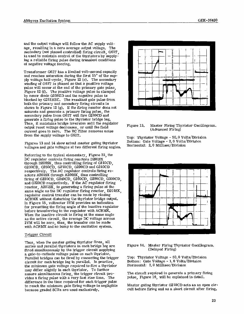
Figures I3 and 14 show actual master gating thyristor voltages and gate voltages at two different firing angles.
Referring to the typical elementary, Figure 23, the DC regulator controls firing reactors D2OlSX through D206SX, thus controlling firing of G2lOCD, G23OCD G25OCD G27OCD, G29OCD and GSlOCD respectibely. Thi AC regulator controls firing re- actors A2OlSX through A206SX, thus controlling firing of G22OCD, G240CD, G260CD, G280CD, G300CD, and G320CD respectively. If the AC regulator firing reactor, ABOlSX, is generating a firing pulse at the same angle as the DC regulator firing reactor, D201SX, regulator control transfer can be made by closing ACRMX without disturbing the thyristor bridge output. In Figure 15, voltmeter 5VM provides an indication for presetting the firing angle of the inactive regulator before transferring to the regulator with ACRMX. When the inactive circuit is firing at the same angle as the active circuit, the average DC voltage across 2VM will be zero, thus, the transfer can be made with ACRMX and no bump to the excitation system.
Trigger Circuit
Thus, when the master gating thyristor fires, all series and parallel thyristors in each bridge leg are fired simultaneously by the trigger circuit supplying a gate-to-cathode voltage pulse on each thyristor. Parallel bridges can be fired by connecting the trigger circuit for each bridge leg in parallel. ln practice, the minimum gate voltage required to fire a thyristor may differ slightly in each thyristor. To further assure simultaneous firing, the trigger circuit pro- vides a firing pulse with a very fast rise time. The difference in the time required for each trigger pulse to reach the minimum gate firing voltage is negligible because graded SCRs are used exclusively.
I I i i i i i i i 1 7
Figure 13. Master Firing Thyristor Oscillogram. (Advanced Firing)
Top: Thyristor Voltage - 50.0 Volts/Division Bottom: Gate Voltage - 2.0 Volts/Division Horizontal: 2.0 Millisec/Division
Figure 14. Master Firing Thyristor Oscillogram. (Delayed Firing)
Top: Thyristor Voltage - 50.0 Volts/Division Bottom: Gate Voltage - 1.0 Volts/Division Horizontal: 1.0 Millisec/Division
The circuit required to generate a primary firing pulse, Figure 16, will be explained in detail.
Master gating thyristor G210CD acts as an open cir- cuit before firing and as a short circuit after firing.
23

Althyrex Excitation System GEK-36430
G170R 470a G171R
4
470a
G4T
Figure 15. Regulator Transfer Circuit.
Refer to I - small firing angle, Figure 16 (b). The series capacitor, ZlC, assures that initially almost all of the supply voltage appears across the primary windings of G216T. Transformer G216T is a pulse transformer with only a small volt-second capacity. After approximately 100 micro-seconds G216T will saturate and the remainder of the supply voltage half- cycle will appear across Z201R. Transformer G216T thus provides a 100 microsecond pulse on all four secondaries when G210CD or G220CD fires. Zener diodes G215ZD, G216ZD, G217ZD, and G218ZD clamp the secondary voltage to produce a square pulse and to prevent gate overvoltage, Figure 16 (d).
If the firing angle is delayed, capacitor Z2C will charge to the peak AC supply voltage, Figure 16 (b), II - large firing angle. Without Z2C the voltage source for delayed firing would be so low that the pulse transformer could not deliver a substantial pulse to the bridge thyristors. With Z2C, firing can be maintained for bridge inversion even into the nega- tive half-cycle of the master firing supply voltage.
During each bridge thyristor conduction period, Figure 11 shows a secondary gate pulse occurring at the same time as a primary pulse in another bridge thyristor leg. Pulse transformers are paralleled in each trigger circuit, Figure 17, to obtain secondary pulses. Transformer G216T supplies a primary
24
pulse to RllCD and transformer G296T supplies a secondary pulse to the return path, R25CD. The top waveform in Figure 18 is the voltage across one bridge thyristor. The bottom waveform in Figure 18 is the gate to cathode voltage of this same thyristor.
GENERATGRACVOLTAGEREGULATOR
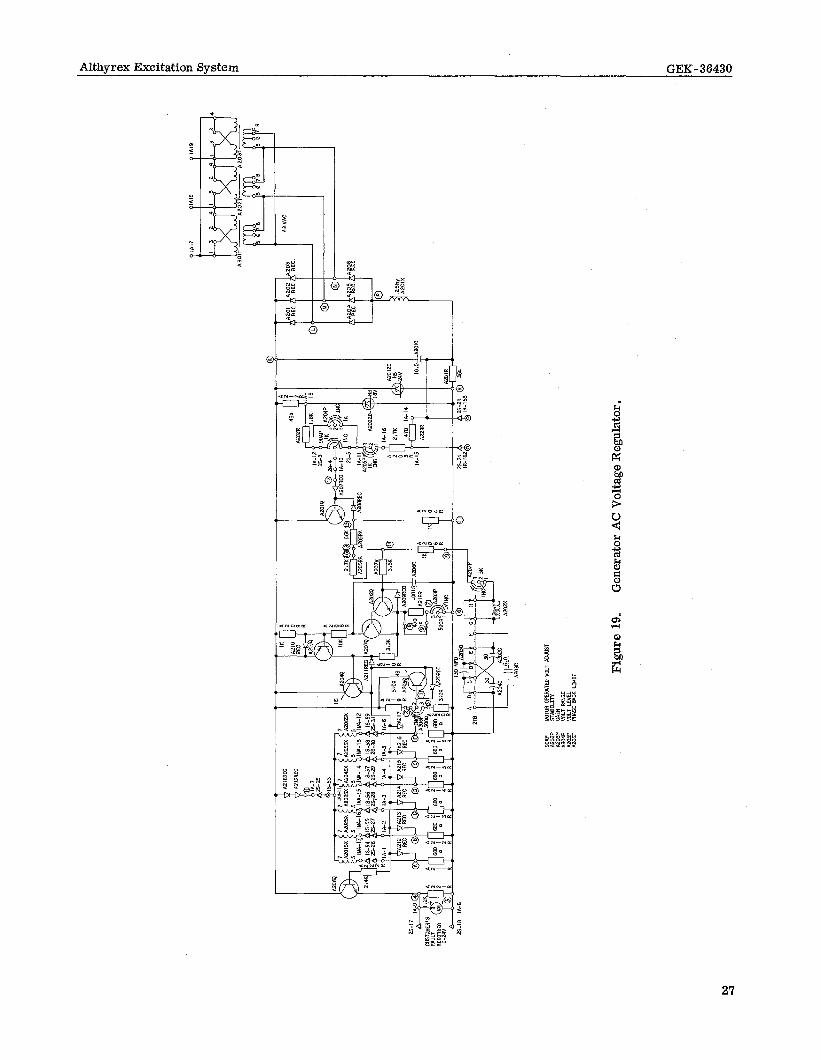
The AC regulator provides automatic operation by controlling firing of the thyristor bridges to hold constant machine terminal voltage. Figure 19 shows the generator AC regulator.
The input to the AC regulator must be 3-phase with a line-to-line voltage between 100 and 125 volts AC, The exciter AC regulator has voltage step down trans- formers connected to the exciter terminals. The generator AC regulator must be supplied from poten- tial transformers at the generator terminals. The input voltage to the generator AC regulator also con- tains a small component of voltage proportional to generator line current.
The regulator supply transformers, A201T, A202T, and A203T, reduce the input AC voltage to approxi- mately 42 volts (at 120 volts input}. Secondary trans- former taps are provided for regulator range adjust- ment, if required. The transformer secondaries supply a three-phase full-wave diode rectifier bridge

Althyrex Excitation System GEK-36430
G4T
A) VOLTAGE
fsoss
B) VOLTAGE ACROSS G2lOCD
C) VOLTAGE ACROSS G216T
D) THYRISTOR GATE VOLTAGE
r------ -- Z3REC O-4 1.0
100
T Zl REC z2c
,Z202R z2iaR I ----e-
1 OOK
L---,
G229REC
15m
2201R F
d
621 OCD
1 .O
1c
.---
1
62 16T G225REC Z225R
G227REC C227R
- -_----__--- -I L G220CD
I-THYRI STIRS FIRE
I. DELAYED FIRING ANGLE 2. ADVANCED FI RI NG ANGLE
iI-- ZENER CLAMPS
-1 sTORS FI RE
Figure 16. Bridge Thyristor Trigger Circuit (Primary Trigger Pulse).
25

Althyrex Excitation System GEK-36430
Rl ICD
G215T POSITIVE LEG “A” PHASE
G216T
RllCD GATE hG215T
G295T
R25CD
NEGATIVE LEG
G296T “B” PHASE
Figure 17. Bridge Thyristor Trigger Circuit. (Primary and Secondary Trigger Pulse)
consisting of rectifiers ABOlREC through A206REC. The DC output of this bridge is used (1) to provide DC power for the transistor circuits, (2) to provide reference voltage for the AC voltage regulator by supplying power to zener diode A202ZD, and (3) to supply voltage feedback proportional to the generator terminal voltage (modified by the line current com- pensation signal).
The current compensation signal can be combined with the generator voltage feedback signal so as to add to it or to subtract from it, depending on whether it is desired to make the regulator decrease terminal voltage or to increase it, as a function of generator line current.
The bridge output is filtered by reactor A201X and capacitor A201C to supply a DC voltage proportional to generator terminal voltage to the sensing circuit and to the zener diodes APOlZD and A202ZD. Zener A201ZD provides a 24 V DC regulated supply and zener A202ZD provides a reference voltage for the voltage regulator. The zener diodes have a very low temperature coefficient so this regulated voltage will not drift.
The sensing circuit consists of resistors A202R, A203R, and A223R, potentiometers 90AP, A204P,
26
and A205P, and zener A202ZD. The difference be- tween the reference voltage and the feedback voltage produces an error current that flows through the base-to-emitter of A201Q. This error current is
Figure 18. Bridge Thyristor Oscillogram.
Top: Thyristor Voltage - 200.0 Volts/Division Bottom: Gate Voltage - 5.0 Volts/Division Horizontal: 2.0 Millisec/Division
Figu
re
19.
Gen
erat
or
AC V
olta
ge
Reg
ulat
or.

amplified by A201Q; thus, any small change in A2OlQ base current produces a larger change in A2OlQ col- lector current. This amplified error current pro- duces an amplified error signal across A204R. The voltage at the emitter of A2OlQ is applied through re- sistors A205RA, A205RB and A207R to the base of a second amplifier stage consisting of transistors AZOZQ, A207Q and A203Q. Components A205RA, A205RB, A206R, A202P, A202X, A202C A203C, A204C, and A205C constitute a lag-lead network in series between the output of the first stage amplifier and the input of the second stage amplifier. The values of the lag- lead network components and A20’7R are selected so that they are low in resistance compared to the input impedance of the second stage. This allows the input impedance to be neglected in calculating the behavior of the network.
Since the three-transistor second stage amplifier em- ploys feedback from the third transistor A203Q into the emitter of the first transistor AZOZQ, the overall gain of this stage is very stable and is relatively un- affected by changes in the current gain of the indivi- dual transistors. Resistor A218R and potentiometer A203P provide a gain adjustment. The use of A218R decreases the gain sensitivity. The collector of A203Q is supplied to the base of A204Q in an emitter follower arrangement in which the emitter load is the control windings of the thy- ristor firing reactors (ASOlSX through AZOSSX). The voltage at the emitter of A204Q determines the reset voltage applied to the reactor control windings and thereby establishes the firing angle of the thyristors, as previously described.
The emitter of A204Q is also applied to the base of A206Q which is an emitter follower for regulator out- put metering. The output metering is in the same sense as the regulator action. If the voltage across the emitter of A204Q increases (becomes more nega- tive) with respect to R, the reset voltage across the firing reactor control windings decreases, the thy- ristor firing angle decreases (thyristors turn-on) and the field voltage increases.
During a sample case of the generator terminal volt- age dropping, such as due to an increase in load, the diode rectifier bridge output will decrease. The volt- age at the wiper of 9OAP will then decrease, causing the emitter voltage of A2OlQ to increase. This in- creased voltage is applied to the base of AZOZQ, causing the emitter voltage of A204Q to increase. This decreases the reset voltage across the firing reactors, which in turn decreases the thyristor firing angle. As the thyristor firing angle decreases (phase- on), generator field voltage will rise, and generator terminal voltage will rise to correct the original error. During a change such as just described, the stabilizing circuit will transiently oppose the initial voltage error and allow the system to return to nor- mal voltage smoothly without oscillating. Should the generator terminal voltage rise due to load rejection, the opposite of the above action would take place.
Phase Back Limit
The phase back limit, potentiometer A206P, can be used to limit the degree to which the thyristor bridge will invert, when it is supplying reverse output voltage during those times when the regulator acts to reduce the excitation rapidly. Resistors A219R and A220R and potentiometer A206P form an adjustable voltage divider for the base of transistor A205Q. If the regu- lator “turns off” the voltage from ‘7 to 16 will decrease. The emitter of A205Q is tied to point 16 so that if the emitter becomes negative with respect to the base A205Q will conduct and prevent point 16 from going more negative. If A206P is turned fully clockwise (dial setting ten) full negative ceiling will be attained.
EXCITER VOLTAGE REGULATORS
The exciter voltage regulator consists of two AC volt- age regulators and two Volts per Hertz regulators. The operation of the Volts per Hertz regulators is explained in instruction book GEK-15021. The opera- tion of the exciter AC voltage regulator is similar to that of the generator AC voltage regulator. The cir- cuitry of an exciter AC voltage regulator differs from a generator AC voltage regulator in that: (1) there is provision for a Volts per Hertz Regulator, and (2) no equivalent of A20’iQ exists in the exciter.
The exciter’s master firing circuit differs from the generator’s master firing circuit in that transfer be- tween regulators is accomplished electronically. The generator requires a relay, ACRM, to accomplish this function. The exciter master firing circuit ex- amines the terminal voltage each AC voltage regu- lator attempts to hold, then selects the regulator which will maintain the lower voltage. Should either AC voltage regulator go above or below the range set by potentiometer RFAP, then the exciter AC Voltage Regulator Failure Alarm would be activated.
DC VOLTAGE REGULATOR (MANUAL)
The DC voltage regulator provides manual control by controlling firing of the thyristor bridges to hold con- stant machine field voltage. The DC voltage regula- tor provides constant excitation by regulating the average DC voltage to the machine field, regardless of AC line voltage changes. Figure 20 shows the generator DC regulator.
The output voltage from the thyristor bridge is fed into the DC regulator through seven reactors. This voltage is applied through D20l.R to D201ZD, setting the regulator reference voltage at 12.0 volts. The filtering action of reactors D201X, D202X, D203X, D204X, D205X, D206X, and D20’7X and potentiometers D201P and D202P produces a DC voltage across D201P that is proportional to the average DC field voltage.

i0
SH.
2 LO
C.
E-7
fDC
-DC
TO S
H.
13
LOC
. D
-S
JZO
IX
D20
2X
D20
3X
D20
4X
DZO
SX
DZO
SX
D20
7X
IMD
.2
IMD
-5
c7
0 ZI
HY.
E
l H
Y.
ZIH
Y.
21 H
Y.
21H
Y.
ZIH
Y.
ZIH
Y.
I “i%
db
K-33
IG-5
‘$
1552
IMD
-6
olG
-3
OIM
D-l
SE
E 6
”. 9
FOR
PRIM
ARY
WIN
DIN
GS
IMD
-7
J
J-3
J
MA
X.
EXC
ITAT
ION
90
MP
MO
TOR
OPE
RAT
ED V
OLT
AD
JUST
LI
MIT
Figu
re
20.
Gen
erat
or
DC V
olta
ge
Regu
lato
r .

Althyrex Excitation System GEK-36430
The firing reactor control windings are connected from the cathode of the reference zener, D2OlZD to D201P, which acts as a voltage divider. If the voltage from the anode of the reference zener point lMD-7, to the anode of D2OlREC point lMD-3 (which is pro- portional to field voltage), is too high, an error reset voltage will appear across the reactor control windings to reduce excitation. The DC regulator thus is a bridge type circuit.
The series resistor-rectifier, such as D204R and D202REC, equalize the reset voltage across each reactor control winding so that each master gating thyristor will be firing at the same respective angle (balanced firing).
Potentiometer D202P can be used to limit the ceiling field voltage of the DC regulator. Clockwise rotation of D202P increases the voltage across D2OlP and consequently its control range.
MAXIMUM EXCITATION LIMIT
The exciter and the generator both have maximum excitation limit circuits to protect the respective fields against sustained over-excitation while the field is controlled from the AC regulator.
Over-excitation is detected by a voltage sensitive relay (relay 59E on the exciter and 59G on the gen- erator), with series voltage dropping resistors, that is connected across the field circuit. If the field voltage exceeds the proportional relay pick-up volt- age, a time delay relay (relay 59ETD on the exciter and 59GTD on the generator) will be energized. Jf the over-excitation condition persists, the time de- lay relay will time out and excitation control will be transferred from the AC regulator (Auto) to the DC regulator (Manual).
The series voltage dropping resistors serve as a coarse adjustment for a voltage sensitive relay that has a pick-up voltage much less than the expected field voltage. The low voltage relay permits a closer setting of the pick-up point with a small dif- ferential between the pick-up and drop-out voltages.
The maximum excitation limits are independent and either the exciter field limit or the generator field limit may operate alone.
UNDER-FREQUENCY LIMIT
The AC regulators sense voltage and are insensitive to changes in frequency. A 14 frequency relay is used to provide protection from excessive volts/hertz on excitation equipment (such as power transformers) for underfrequency operation in AC regulator (Auto). If the generator is operated at reduced speeds., the 14 frequency relay will prevent operation in either the exciter or the generator AC regulator by trans- ferring field control to the DC regulator,
MAXIMUM CURRENT LIMIT
The maximum current limit provides a ceiling or top limit to the DC current that can be applied to the gen- erator field, and also protects the excitation system by limiting the current that can be supplied by the thyristor bridges when in generator AC regulator (Auto) control. See Figure 21.
A current transformer in each AC line to the thyris- tor bridge circuits provides a voltage proportional to current due to its fixed load resistor (R750R, R751R and R752R). This voltage is rectified by a three-phase full wave bridge (rectifiers R754REC through R759- REC). Capacitor R750C holds the bridge output volt- age to near peak voltage of the highest single phase input. The voltage across R750C is thus nearly pro- portional to the highest AC phase current into the generator thyristor bridge circuits.
The DC voltage across R750C is also applied across R750P, which acts as a voltage divider, so that the voltage at point k is proportional to current. Lf this voltage exceeds the 6.8 volt level of R750ZD, current will flow from base-to-emitter through R750Q. This causes a larger current flow from collector-to emitter through R750Q. This emitter follower action of R750Q applies reset voltage to the firing reactor control wind- ings (A201SX through A206SX) to decrease excitation, thereby reducing the overcurrent.
A separate power supply, R750T, allows R750P re- sistance to be high enough not to add extra burden on the CTs. Transformer R750T supplies a single-phase bridge, R750REC through R753REC, and the DC output is filtered by R753R and R751C. Zener R751ZD main- tains a constant 36 volt supply.
FAULT SUPPRESSION CIRCUIT
In the event of a fault condition, such as a generator collector ring fault, the excessive field current will be sensed by the 76 relay. If the excessive field cur- rent is sustained, 76TD will operate to trip the master firing circuit on the exciter thyristor bridge. If the excessive current is a result of field forcing, 59GTD/ X will will sense field voltage and operate to pick up 76X to lock out 76TD.
The 76 relay is connected across the R750C capacitor in the maximum current limit circuit. The relay then senses a voltage proportional to the highest single phase input,
REACTIVE CURRENT COMPENSATOR (RCC)
The RCC is used to equalize division of reactive kva between generators when two or more generators with individual regulators are operating in parallel. As shown in Figure 22, the adjustable reactor winding (GlT) is connected to the secondary of a current transformer in one of the generator lines, while the insulating winding is connected in one phase of the
30
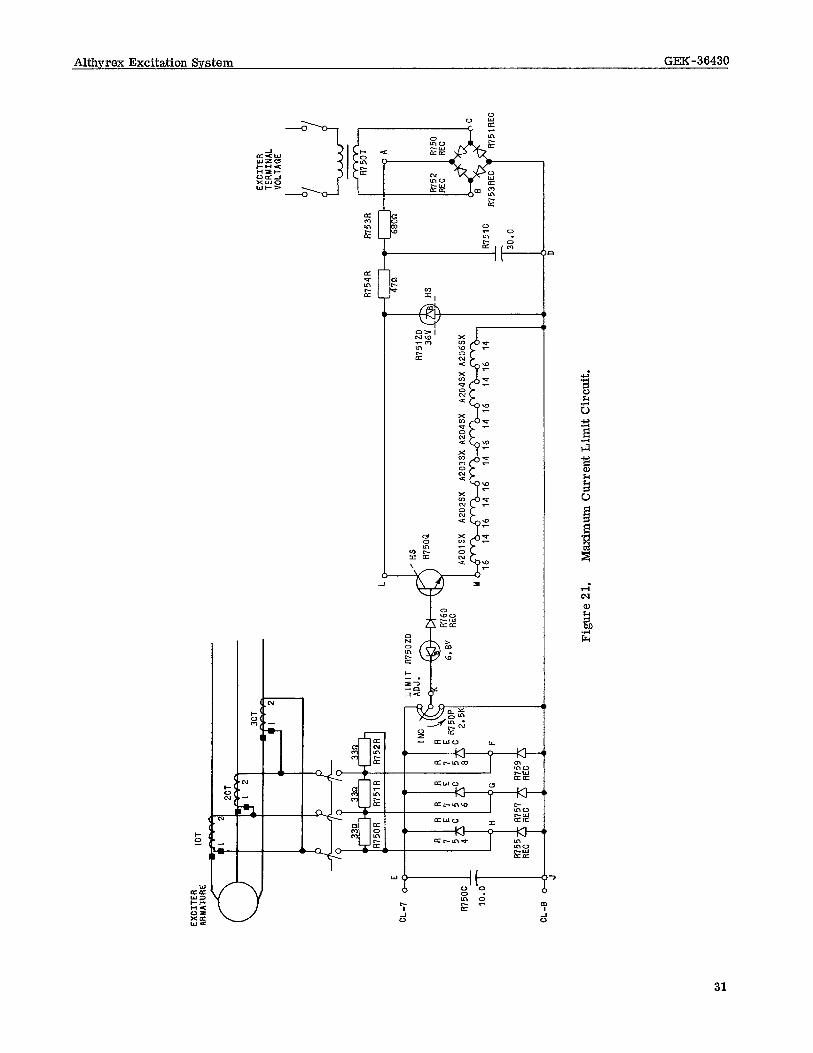
EXCI
TER
ARM
ATU
RE
ICT I
I 33
n
k R75
0R R R
I : c’
4
H
LIM
IT
R75
0ZD
Figu
re
21.
Max
imum
C
urre
nt
Lim
it C
ircui
t.
EXC
ITER
TE
RM
INAL
VO
LTAG
E
d b
L&J
R75
3R
m

Althyrex Excitation System GM-36430
/--
r-- -,
9 I r~-~----------- ~ , ,r---- ---- ------ --- 1 1 I '
; to' NI , Ii-1 I I I ' 14C' I InI , I I ̂ 5 I
7i )chcu I 1 129 I 1 I ’ ,I ; E I ! r--l
32

three-phase AC regulator feedback voltage.
IT IS ESSENTIAL THAT BOTH WINDINGS OF THE COMPENSATOR BE CONNECTED IN THE SAME GENERATOR PHASE - USUALLY PHASE 2.
The compensator will vary the AC regulator feedback voltage mainly as a function of the reactive current. See Figure 22-I. If overexcited reactive current in- creases, the average three-phase feedback voltage supplied to the AC regulator will increase. The regu- lator will act to decrease excitation, thereby de- creasing the overexcited reactive current. If underexcited reactive current increases, the aver- age three-phase feedback supplied to the AC regulator will decrease, The regulator will act to increase ex- citation, thereby decreasing the underexcited reactive current. The effect of the compensator can be in- creased by increasing the reactance in the current- transformer secondary circuit with tap switches GlSW and GOSW.
If two generators are connected through transformers, one’s winding may be reversed to obtain the opposite effect of that described above. This makes it possible to adjust the apparent transformer impedance to an optimum value (@to 6 percent) improving system voltage regulation. The compensator is adjustable in one-volt steps, on the basis of five amperes in the current-transformer secondary, by means of two manually operated tap switches. One of the tap switches gives coarse ad- justment and the other gives fine adjustment. The voltage across this winding in the AC regulator feed- back circuit is proportional to the current in the cur- rent transformer secondary winding. With five am- peres flowing through the compensator and with the reactance all cut in, the total drop is 24 volts. This is equivalent to about 36 percent line-to-neutral volt- age drop in one signal lead to the regulator, or an average effect of approximately 12 percent line-to neutral voltage drop on a three-phase basis (at zero power factor).
The compensator is built with two independent wind- ings, as shown in Figure 22, so that the current and potential transfomer secondaries are electrically separate and both may be grounded. ACTIVE -REACTIVE CURRENT COMPENSATOR b%RCC)
In certain special applications, an active-reactive current compensator is used to reproduce in minia- ture at the regulator, the resistance and reactance between the generator and some predetermined point in the system. The function of the compensator is to lower the signal voltage to the AC regulator as the generator load increases, thereby causing the regu- lator to maintain normal voltage at some predeter- mined point in the system, regardless of changes in the voltage drop over the system impedance between the generator and this point. See Figure 22-H.
Where line-drop compensation is required on several generators in a station, provision can be made to pre- vent interference between the compensators. This is accomplished by special connections of the current transformer and compensators.
The reactance of the compensator is divided into a number of equal sections. Taps are brought out from these sections and connected to independently adlust- able tap switches, one having coarse adjustment and the other having fine adjustment. The reactance is variable in one-volt steps based on five amperes in the current. transformer. It has a total of 24 steps, and will introduce a maximum of 24 volts total drop in the AC regulator signal voltage circuit, with five amperes in the current-transformer secondary. This voltage drop is proportional to the current flowing in the compensator. The resistance portion of the com- pensat@n is a 5 ohm rheostat which produces 25 volts drop in the regulator signal with five amperes in the CT secondary. Figure 22 shows the connections for this device when used with a single generator. Insulating windings are provided for both the reactor and resistor to permit grounding the current and potential-transformer sec- ondaries separately. It is essential that the current transformer be in the same phase as the single-volt- age line in which the compensator is connected. UNDER-EXCITED REACTIVE AMPERE LIMIT (U. R. A. L. ) This accessory is described by separate instructions GEK-4716.
POWER SYSTEM STABILIZER
This accessory is described by separate instructions GEK-36416.
RELAY AND CONTROL CIRCUIT
All essential relaying and control circuits are oper- ated on a DC power source for maximum reliability. This DC is usually 125 volts DC. In some applica- tions, the relaying may be at 250 volts DC. A typi- cal application is illustrated in Figure 23. Most applications require different circuits to fit the user’s practice; however, the general mode of operation is similar to the following description.
All essential relays are latched relays. Loss of DC control power will not disturb the mode of excitation system operation. During loss of DC power, the exciter field breaker can be tripped mechanically at the breaker.
SEQUENCE OF OPERATIONS
A typical sequence of operations for each of the four states Start, Manual, Automatic and Stop follows. It is assumed that the progression of states is from Start to Manual, Manual to Automatic, and Automatic to stop.
Start
1. Turn SBM switch to Start.
33

Althyrex Excitation System GEK-36430
2. Assume break before make operation of SBM switch.
3. Break
a. E opens.
b. Relay 5 drops out.
(1) N. 0. contacts of 5 open, causing Stop light to go out.
(2) N.O. contacts of 5 open, relay 5X2 drops out.
4. Make
a 43cs closes. l start
b. Relay 1 picks up.
c. Relay 435 picks up.
(1)
(2)
(3)
N.O. contacts of 43s close, Start light illuminates.
N. C. contacts of 43s open, removing power from 90AR, 9OAL, 90MR and 90ML.
N.O. contacts of 43s close, relay 9CR picks up.
(a) N. 0. contacts of 9CR close to apply power to 9OMR and 90ML to pre-position the manual voltage adjustor to AFNL.
d. Pre-positioning of the manual voltage ad- justor causes OCRM to pick up.
(1)
(2)
(3)
(4)
Contacts of OCRM cause relay OCRMX to pick up.
N.O. contacts of OCRM close, relay OCR picks up.
N.O. contacts of OCRM close, apply- ing power to the Breaker Ready light through a normally closed contact of 41E AUX.
N.O. contacts of OCRM close, relay OCR picks up.
(a) Contacts of OCR cause relay OCRX to pick up.
(b) N. 0. contacts of OCR close, relay OCRY picks up.
e. Operator closes exciter field breaker 41E.
(1) N. C. contacts of 41E AUX open, caus- ing Breaker Ready light to go out.
(2) N.O. contacts of 41E AUX close, re- lays 53 and 53TD pick up.
(a) N.O. contacts of 53 close, the ex- citer field is flashed until relay 53TD times out.
(b) N. C. contacts of 53TD open, relay 53 drops out.
f. Operator should now transfer to Manual.
Manual
1. Turn SBM switch to Manual.
2. Assume break before make operation of the SBM switch.
3. Break
43cs a. Start owns.
b. Relay 435 drops out. (1). N. 0. contacts of 43s open, causing
Start light to go out.
(2) N. C. contacts of 43s restore power to 9OAR, 9OAL, 9OMR and 90ML.
(3) N. 0. contacts of 43s open and drop out 9CR.
(a) Power is removed from 9OMR and 90ML, via N. 0. contacts of 9CR. (Power remains applied to 9OAR, 9OAL, 90MR and 90ML through N. C. contacts of 435. )
4. Make
a, 43cs closes. Manual
b. Relay 43M picks up.
(1) N.O. contacts of 43M close. As a result, relay 43TR is picked up,
(2) N.O. contacts of 43M close, Manual light illuminates.
c. The manual raise-lower pushbuttons can now be used to control the generator ter- minal voltage by operating the DC voltage adjustor. The AC voltage adjustor may also be operated, but since the control is in Manual, operation of the AC voltage ad- justor will have no effect on terminal voltage.
34

Althyrex Excitation System GEK-36430
d. Exciter terminal voltage will build up pro- portional to frequency under the control of the Volts/Hertz regulators until 57 Hz.
e. Exciter AC regulators control exciter ter- minal voltage above 5’7 Hz.
f. Relay 14 picks up above 5’7 Hz.
(1) N.O. contacts of 14 close, relay 14 AUX picks up.
(a) N. 0. contacts of 14 AUX close, relay 5CR picks up.
g. Before transferring to Automatic, the AC regulator should be adjusted to match the DC regulator as indicated by a null condi- tion of the transfer voltmeter.
Automatic
1. Turn SBM switch to Automatic.
2. Assume break before make operation of SBM switch.
3. Break
a, 43cs ~ opens. MZUlU3.l
b. Relay 43M drops out.
(1) N.O. contacts of 43M open, causing Manual light to go out.
4. Make
a.
b.
c.
stop
43cs - closes. Auto Relay 43A picks up.
(1) N.O. contacts of 43A close, Auto- matic light illuminates.
(2) N.O. contacts of 43A close. As a result, relay ACRM is picked up.
The AC regulator automatically adjusts the generator field voltage to obtain a constant terminal voltage. When in Automatic, the DC regulator should be tracked to keep the transfer voltmeter at zero. To transfer back to Manual, the DC regulator should be balanced to the AC regulator in order to avoid a system disturbance.
1. Turn SBM switch to Stop.
2. Assume break before make operation of SBM switch.
3. Break
43cs a Auto Opens. b. Relay 43A drops out.
(1) N.O. contacts of 43A open, causing Automatic light to go out.
(2) N.O. contacts of 43A open. As a re- sult, relay ACRM drops out.
4. Make
a. 43cs closes. stop
.
b. Relay 5 picks up.
(1)
(2)
(3)
(4)
(5)
N.O. contacts of 5 close, Stop light illuminates.
N.C. contacts of 5 open, relay 43TR drops out.
N.O. contacts of 5 close, 1 trip coil is energized and relay 1 drops out.
N.O. contacts of 5 close, OCRM trip coil is energized and relay OCRM drops out.
(a) Contacts of OCRM cause relay OCRMX to drop out.
N.O. contacts of 5 close, relay 5X2 picks up.
(a) N. 0. contacts of 5X2 close, OCR trip coil is energized and relay OCR drops out.
(1) Contacts of OCR cause relay OCRX to drop out.
(2) N.O. contacts of OCR open, relay 53TD drops out.
(b) N. 0. contacts of 5X2 close, OCRY trip coil is energized and relay OCRY drops out.
c. Relay 14 drops out below 5’7 Hz.
(1) N.O. contacts of 14 open, relay 14 AUX drops out.
(a) N.O. contacts of 14 AUX open, relay 5CR drops out.
d. Operator should now open exciter field breaker 41E.
The following chart summarizes the preceding se- quence of operations and is valid only for the pre- viously specified progression of states.
35

Althyrex Excitation System GEK-36430
RELAY
1 43s Start Light 90AR 90AL 90MR 90ML 9CR OCRM OCRMX OCR Breaker
Ready Light OCRX OCRY 41E 53 53TD 43M 43TR Manual Light 14 14 AUX 5CR 43A ACRM Auto Light 5 Stop Light 5x2
PICKED UP IN
START START START MANUAL MANUAL START, MANUAL START, MANUAL START START START START
START START START START START START MANUAL MANUAL MANUAL MANUAL MANUAL MANUAL AUTO AUTO AUTO STOP STOP STOP
DROPPED OUT IN
STOP MANUAL MANUAL START START STARTMANUAL STARTMANUAL MANUAL STOP STOP STOP
START STOP STOP STOP START STOP AUTO STOP AUTO STOP STOP STOP STOP STOP STOP START START START
MISCELLANEOUS FUNCTIONS
Shaft voltage suppressor circuits are provided across exciter and generator field circuits to provide a ground path for AC currents. This prevents the ripple component of the field rectifier output voltage from inducing voltage in the rotor shaft. Shaft volt- age tends to cause current flow across bearings, which could shorten bearing life.
Generator and exciter field ground detector relay panels are provided, These are described by sep- arate instructions GEK-36424.
1 WARNING 1
WHEN REPLACING GENERATOR OR EXCITER SLIP RING BRUSHES, DIS- CONNECT GROUND (TERMINAL 1TB-C) FROM FIELD GROUND DETECTOR RELAY PANEL AND DISCONNECT GROUND FROM SHAFT VOLTAGE SUPPRESSION CIRCUIT.
Transducers may be provided to transmit an isolated low power level signal to indicate generator field current and voltage.
Control switches and a transfer voltmeter may be provided for mounting on the user’s control board.
MAINTENANCE
This excitation system is static, having no moving parts except for relays and instruments, so little maintenance should be required. All cubicles should be cleaned regularly with a vacuum cleaner.
DO NOT USE A METAL NOZZLE ON THE VACUUM CLEANER. A METAL NOZZLE CAN CAUSE COMPONENT DAMAGE. USE A RUBBER NOZZLE.
If excessive vibration is present, then all screw con- nections should be checked periodically. Space heaters should be used to prevent an accumulation of moisture.
In some high ambient temperature applications, some cubicles may be equipped with ventilation fans. In unusually dusty conditions, ventilation filters may be used. If ventilation filters are supplied, they should be periodically cleaned by washing in warm, not hot, sudsy water.
All thyristors should be checked weekly. All neon lights on each thyristor bridge must be lit. A neon light out indicates a faulty thyristor, blown fuse or faulty lamp. The thyristors used in the bridges are of the silicon controlled rectifier type and are not known to age. Therefore, they are either good or faulty and if faulty they should be removed. Thyris- tors normally fail by short circuit and will have a very low and approximately equal forward and re- verse resistance. No exact values can be given as different ohmmeters use different battery voltages and will, therefore, give different readings, The best way to obtain a calibration of what the forward and reverse resistance should be for a given meter is to actually measure these values on a thyristor known to be good.
When replacing or checking thyristors, no more than one bridge should be disconnected at a time. If a thyristor is to be replaced, care should be taken to insure the replacement is of an identical grade as the removed thyristor,
PROCEDURE FOR INSTALLING SCRs
The procedure for installing replacement clamp-on type SCRs is as follows:
1. Clean the heat sink surface and the rectifier base. Use alcohol, then wipe with a clean cloth.,
2. Lightly coat the heat sink surface and the rectifier base with Dow Corning #3 silicon grease.
36

Althyrex Excitation System GEK-36430
3. Using approximately eight light strokes, lightly buff the heat sink surface and the rectifier base with a clean fine wire brush.
4; Re-apply a smaller amount of silicon grease to the heat sink and the rectifier.
5. Place SCR on its heat sink, Place clamp on rectifier, insert S/16” bolts, apply 3 drops of light machine oil (3 in 1 - SAE 20) to threads, and loosely attach clamp. Do not use lockwashers.
6. Attach the pigtail loosely to its terminal. This allows the pigtail to assume its natural lie, which should cause the cell to rotate to its preferred posi- tion. The cell, thus aligned! should be free from undue stress, pigtail distortion and header distortion.
7. Tighten the clamping bolts finger tight. Do not cock the clamp on the cell. Then, using a torque wrench, tighten each bolt alternately, one-half turn at a time.
8. Tighten each bolt to 352 inch-pounds of torque. Bo not exceed 35 inch-pounds.
9. Do not pull the clamp past flat,
If the generator thyristor bridges are to be out of service with the ambient temperature below freezing, the cooling water should be drained from the heat sinks and piping. A drain plug is provided in the lowest point in each bridge cooling water circuit. Care should be taken to replace drain plugs and res- tore water flow before the thyristor bridges are again energized.
The field breaker trip circuit indicating light should be checked weekly to indicate integrity of trip coil. Field ground detecting relays should be tested weekly. Alarm circuit relays, such as bridge overtempera- We, have test pushbuttons to test relay pick-up and remote alarm and should be tested weekly.
The generator should be transferred to DC (manual) regulator periodically, to check circuit operation. This transfer should be smooth and control on MAR- UAL operation should be smooth. The transfer back to AC (Auto) regulator should also be smooth.
The U. R. A. L. output meter (BlVM) should be checked weekly. It should normally read slightly negative.
User may choose to operate generator in the under- excited region periodically to check U. R. A. L. operation.
Magnetically operated contact-making devices should be ins petted regularly in accordance with applicable instructions. Brushes in motors (for all motor- driven adjustments), all open rheostats, potentiome- ters and variable transformers should be inspected every six months under normal operating conditions. Where unusually dusty or other abnormal atmospheric conditions exist, they should be inspected every six weeks. If arcing occurs or if the brushes are badly worn, they should be replaced.
For planned outages, the following maintenance should be performed:
1. General cleaning--blower or vacuum cleaner.
2. Check all brushes, motors, and rheostats.
3. Inspect all relays--operation and contacts.
4. Check for any loose connections on large wire, bus, and large thyristors.
5. Check all large thyristors and rectifiers (those requiring heat sinks) and all large fuses with an ohm- meter.
TROUBLESHOOTING
The best aid for troubleshooting is a thorough study of the particular circuit in the “Principles of Operation. ’
RENEWAL PARTS
When ordering renewal parts, the following informa- tion should be given:
1. Catalog number stamped on the part, with com- plete description including use and location.
2. Complete nameplate data appearing on the assembly that included the component.
3. If possible, data on original order on which equipment was first supplied including all numerical references.
37/38

Altlyrex Excitation System GEK-36430
Drive Systems Product DepartmenteGeneraI Electric Company,
Waynesboro, Virginia 22980
8-73 (600) GENERAL @ ELECTRIC
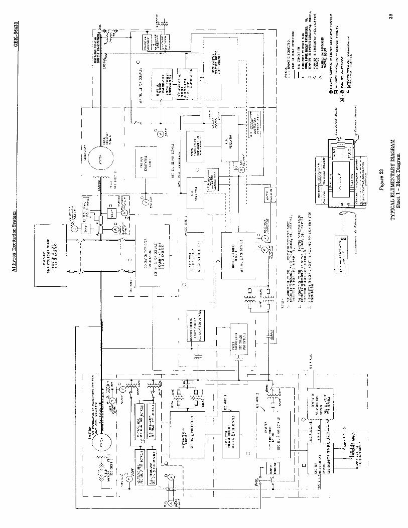
Alth
vrex
Ex
citat
ion
Svst
em
GEK-
3643
0
r .~
--
- -
- -.
--
- -
-8
r- Lsf-
-- l r
I I
__---
--..J
Figu
re 2
3
TYPI
CAL
ELEM
ENTA
RY
DIAG
RAM
Sh
eet 1
- Bl
ock
Diag
ram
39

t N
+..-.-------
I I
I
L------l -1


I L ---- -------__- I C$ ~----~--T--1, ,
; ,‘. 3 -, - 1 @ \\ _:
I- I
I’ L----- ---- :

Alth
vrex
Ex
citat
ion
Svst
em
GEK-
3043
0
L-*--
-----
-l-+-
-[L---
-cui
-----
-----A
L A2
C
____
--_---
------
- I
Figu
re 2
3
TYPI
CAL
ELEM
ENTA
RY
DIAG
RAM
Sh
eet 5
- Ex
citer
Reg
ulato
r #l
43

rei=7----
r
-i I
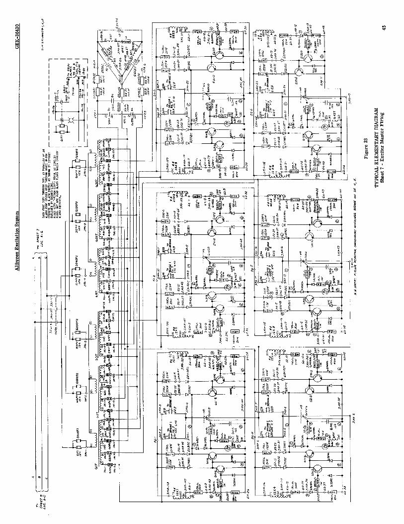

Alth
~rex
Ex
citat
ion
Svste
m
GEK-
3643
0
I I I I I I I I I I I
Figu
re
23
TYPI
CAL
ELEM
ENTA
RY
DIAG
RAM
Sh
eet
8 -
Excit
er
Thyr
istor
Br
idge
46

,
:I
---
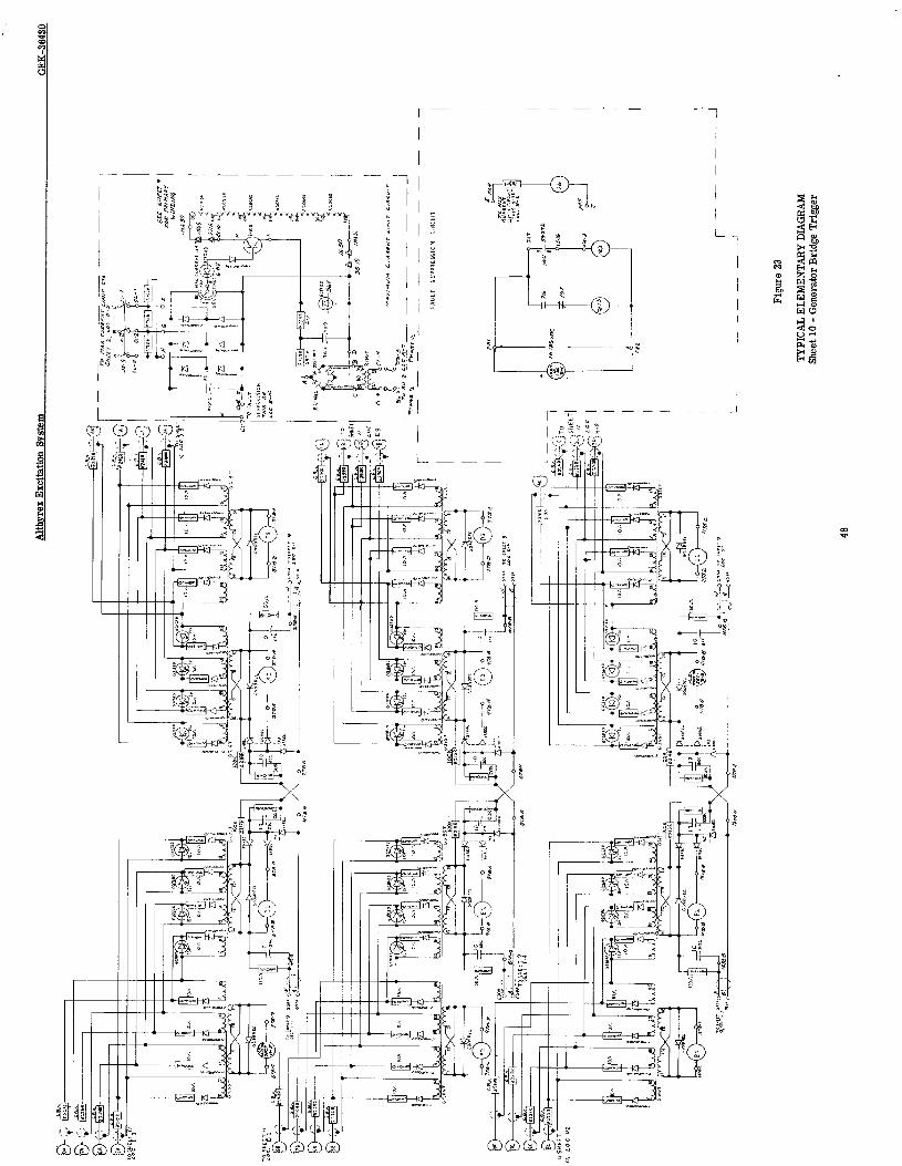
r
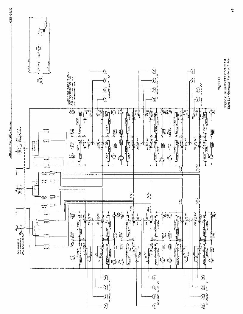
r
-- - I
I


m
/ I I I I I I I I I I I I I
/ I I I I I I I I I
I I I
! g [-q---t I $
I Y I .

Alth
yrex
Ex
citat
ion
Syste
m
GEK-
3643
0
Lx---
- I--
,:&
$+J
CUEl
Ci
E CU
EiCL
E L,
CHTS
Ll
LiHT
S Fi
gure
23
TYPI
CAL
ELEM
ENTA
RY
DIAG
RAM
Sh
eet
14 -
Gen
erat
or
Cont
rol
52


Althv
rex
Excit
ation
Sy
stem
GEK-
3643
0
Figur
e 23
TYPI
CAL
ELEM
ENTA
RY
DIAG
RAM
Shee
t 16
- P
ower
Sy
stem
Stab
ilizer
54
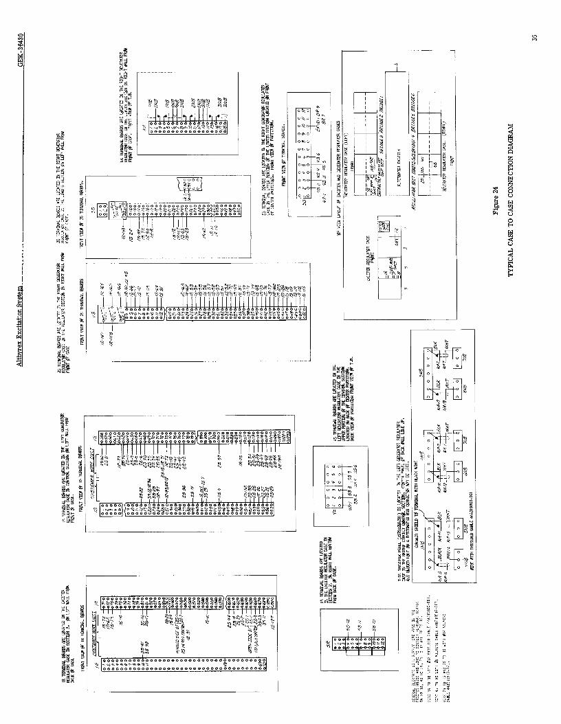
WVlIW
Ia NOIJXINN03
3SV3 OsL3SV3
W31dhL

AltlI
YreX
Ex
cita
tion
Syst
em
GEK-
3643
0
r-
Figu
re 2
5
TYPI
CALC
ASE
TOCU
STO
MER
CONN
ECTI
OND
IAG
RAM
56
Altlwrex Excitation System GEK-36430 --
Drive Systems Product Department@ General Electric Company,
Waynesboro, Virginia 22980
H-73 (GO01 GENERAL @ ELECTRIC . . . . ;.