alternator identification · pdf filealternator identification alternators six different...
TRANSCRIPT
ALTERNATOR IDENTIFICATION
ALTERNATORS
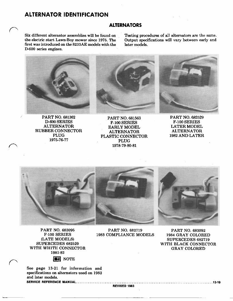
Six different alternator assemblies will be found on , Testing procedures of all alternators are the same. the electric start Lawn-Boy mower since 1975. The Output specifications will vary between early and first was introduced on the 8233AE models with the later models. D-600 series engines.
PART NO. 681362 PART NO. 681563 PART NO. 682529
ALTERNATOR EARLY MODEL LATER MODEL RUBBER CONNECTOR ALTERNATOR ALTERNATOR
PLUG PLASTIC CONNECTOR 1982 AND LATER
D-600 SERIES F-100 SERIES F-100 SERIES
1975-76-77 PLUG 1978-79-80-81
PART NO. 683095 PART NO. 682719 PART NO. 683092
(LATE MODELS) SUPERCEDES 682719 SUPERCEDES 682529 WITH BLACK CONNECTOR
F-100 SERIES 1983 COMPLIANCE MODELS 1984 GRAY COLORED
WITH WHITE CONNECTOR GRAY COLORED 1981-82
NOTE
See page 13-21 for information and specifications on alternators used on 1983 and later models. SERVICE REFERENCE MANUAL. .13-19
REVISED 1983
ALTERNATOR TESTING
ALTERNATOR TESTING PROCEDURES
NOTE
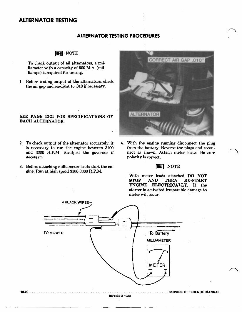
To check output of all alternators, a mil- liameter with a capacity of 500 M.A. (mil- liamps) is required for testing.
1. Before testing output of the alternators, check the air gap and readjust to .010 if necessary.
SEE PAGE 13-21 FOR SPECIFICATIONS OF EACH ALTERNATOR.
2.
3.
To check output of the alternator accurately, it is necessary to run the engine between 3100 and 3300 R.P.M. Readjust the governor if necessary.
Before attaching milliameter leads start the en- gine. Run at high speed R.P.M. 3100-3300
4. With the engine running disconnect the plug from the battery. Reverse the plugs and recon- nect as shown. Attach meter leads. Be sure polarity is correct.
NOTE
With meter leads attached DO NOT
ENGINE ELECTRICALLY. If the starter is activated irreparable damage to meter will occur.
STOP AND THEN RE-START
4 BLACK WIRES
TO MOWER To Battery
\ MILLIAMETER
13-20. .SERVICE REFERENCE MANUAL REVISED 1983
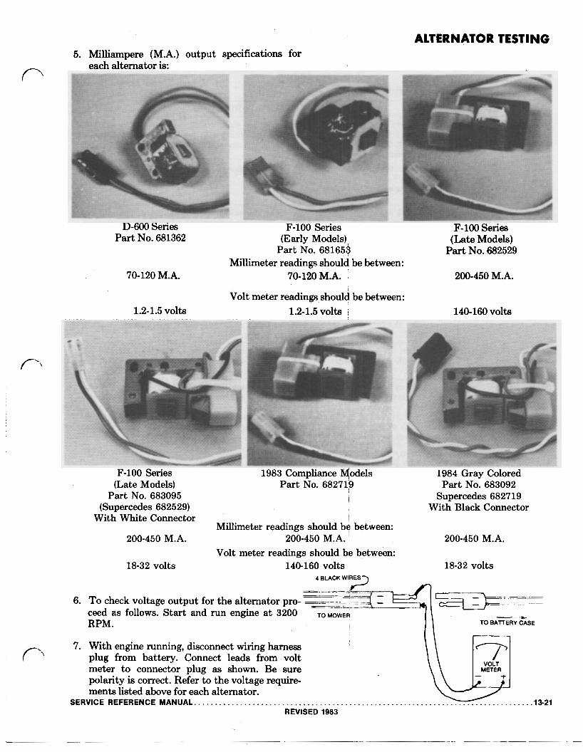
ALTERNATOR TESTING 5. Milliampere (M.A.) output specifications for
each alternator is:
D-600 Series Part No. 681362
F-100 Series (Early Models),
Part No. 681653
F-100 Series (Late Models)
Part No. 682529 Millimeter readings should be between:
70-120 M.A. 70-120 M.A. 200-450 M.A.
Volt meter readings should be between: 1.2-1.5 volts 1.2-1.5 volts 140-160 volts
F-100 Series 1983 Compliance Models 1984 Gray Colored (Late Models) Part No. 682719 Part No. 683092
Part No. 683095 Supercedes 682719 (Supercedes 682529) With Black Connector
With White Connector Millimeter readings should be between:
Volt meter readings should be between: 200-450 M.A. 200-450 M.A. 200-450 M.A.
18-32 volts 140-160 volts 18-32 volts 4 BLACK WURES
6. To check voltage output for the alternator pro- ceed as follows. Start and run engine at 3200 TO MOWER RPM. TO BATTERY CASE
7. With engine running, disconnect wiring harness plug from battery. Connect leads from volt meter to connector plug as shown. Be sure METER
polarity is correct. Refer to the voltage require- ments listed above for each alternator.
SERVICE REFERENCE MANUAL REVISED 1983
TROUBLE SHOOTING THE ALTERNATOR PART NO. 681 362 CHARGING SYSTEM
MODEL 8233AE, 8234AE & 8235AE D-600 SERIES
STARTER DOES NOT TURN ENGINE: BATTERY RUN DOWN BATTERY VOLTAGE BELOW 10 VOLTS Alternator Not Charging Battery run down. The resistance on the pins of plug “H” should read LOW
with V.O.M. leads in one direction and HIGH with leads reversed. (Meter on RX 1) . This checks for bad diodes. A low resistance or high resistance in both directions indicates defective diodes. The output voltage of plug “E” with the engine running on: Normal (high) speed 1.2 to 1.5 Volts (Using a 20,000 ohms per volt meter)
Ground Wire “M” Open Check resistance at plug “E”. With the’ self-propelled handle in neutral, and or Loose the key switch in the ‘START’ position, and plugs “G” & “H” disconnected,
the circuit reads: A GOOD CIRCUIT READS SHORTED A BAD CIRCUIT READS HIGH RESISTANCE (METER ON RX 1)
Key Switch Defective Key switch in the ‘START’ position. A good switch reads SHORTED on termi- nals 2 & 3. A bad switch will read 1 or more ohms. (Meter on RX 1 )
Starter Motor Defective Check voltage at starter plug “A” when key switch is in ‘START’ position. Voltage is to be above 10 volts. The resistance between the terminals on plug “B” should read approximately .3 ohms resistance for a good motor. (Meter on RX 1 ) Turn motor for lowest reading.
Self-propelled Interlock When the self-propelled handle is in neutral, the interlock switch should be Switch Open closed. A good switch reads SHORTED on the pins of plug “D”. (Meter on
RX 1 )
Short Circuit Battery run down. The resistance on pins of plug “E” (with all other plugs connected, self-propelled in neutral, and, key switch in “off” position) should read as follows:
With volt-ohmeter on RX 1 the low reading will be between 15 ohms and 20 ohms. With the volt-ohmeter on its highest setting, the high reading will be MEG ohms.
Alternator Diodes Battery run down. Disconnect plugs “A”, “C” and “J”. Connect a 20,000 Leaking ohms per volt volt meter as follows:
Use 15 volt D.C. scale (Min.). Disconnect plug “E”. Reconnect plug “E” so that the male pin of plug “E” and the female of plug “F” are not con- nected. Connect the positive lead of the volt meter to the male pin of plug ‘‘E”. Connect the negative lead of the volt meter to the female of plug “F”. The meter should read zero. A reading of more than one volt indicates excessive leakage which could run the. battery down during storage.
____-- __-
ENGINE STOPS WHEN KEY SWITCH IS IN ‘RUN’ POSITION: Key Switch Defective Key in ‘RUN’ position, the resistance between terminals 1 & 2 on plug “ K ”
reads less than 1 MEG ohm. ENGINE DOES NOT STOP IN KEY IN ’OFF’ POSITION:
Key Switch Defective Key on ‘OFF’ position, the resistance between terminals 1 & 2 on plug “ K ” reads INFINITE resistance. (Meter on RX 100)
Ground Lead “M” Open Check terminal 2 on plug “J” to engine. If the resistance reads INFINITE at Ground the ground is bad. (Meter on RX 100) Connection at “L” Open Lead disconnected.
13.22. .SERVICE REFERENCE MANUAL REVISED 1983

ELECTRIC START SERVICING D-600 SERIES WIRING DIAGRAM NICKEL CADMIUM BATTERY
LOCKOUT SWITCH STARTER
KEY SWITCH
FIGURE KEY IN “OFF” POSITION
LOCKOUT SWITCH STARTER
C.D.
FIGURE
LOCKOUT SWITCH
2 KEY IN ‘START’ POSITION
ST C.D.
IGNITION A
SERVICE REFERENCE FIGURE 3 KEY IN "RUN" POSITION
MANUAL 13-23 REVISED 1983
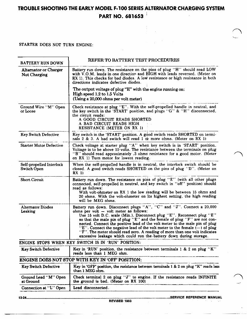
TROUBLE SHOOTING THE EARLY MODEL F - l o 0 SERIES ALTERNATOR CHARGING SYSTEM PART NO. 681653
STARTER DOES NOT TURN ENGINE:
BATTERY RUN DOWN
Alternator or Charger Not Charging
Ground Wire “ M ” Open or Loose
Key Switch Defective
Starter Motor Defective
Self-propelled Interlock Switch Open
Short Circuit
Alternator Diodes Leaking
REFER TO BATTERY TEST PROCEDURES
Battery run down. The resistance on the pins of plug “H” should read LOW with V.O.M. leads in one direction’ and HIGH with leads reversed. (Meter on RX 1). This checks for bad diodes. A low resistance or high resistance in both directions indicates defective diodes.
The output voltage of plug “E” with the engine running on: High speed 1.2 to 1.5 Volts (Using a 20,000 ohms per volt meter)
Check resistance at plug “E”. With the self-propelled handle in neutral, and the key switch in the ‘START’ position, and plugs “G” & “H” disconnected, the circuit reads:
A GOOD CIRCUIT READS SHORTED A BAD CIRCUIT READS HIGH RESISTANCE (METER ON RX 1)
Key switch in the ‘START’ position. A good switch reads SHORTED on termi- nals 2 & 3. A bad switch will read 1 or more ohms. (Meter on RX 1)
Check voltage at starter plug “A” when key switch is in ‘START’ position. Voltage is to be above 10 volts. The resistance between the terminals on plug “B” should read approximately .3 ohms resistance for a good motor. (Meter on RX 1) Turn motor for lowest reading. When the self-propelled handle is in neutral, the interlock switch should be closed. A good switch reads SHORTED on the pins of plug “D”. (Meter on RX 1) Battery run down. The resistance on pins of plug “E” (with all other plugs connected, self-propelled in neutral, and key switch in “off” position) should read as follows:
With volt-ohmeter on RX 1 the low reading will be between 15 ohms and 20 ohms. With the volt-ohmeter on its highest setting, the high reading will be MEG ohms.
Battery run down. Disconnect plugs “A” , “C” and “J”. Connect a 20,000 ohms per volt volt meter as follows:
Use 15 volt D.C. scale (Min.). Disconnect plug “E”. Reconnect plug “E” so that the male pin of plug “E” and the female of plug “F” are not con- nected. Connect the positive lead of the volt meter to the male pin of plug “E”. Connect the negative lead of the volt meter to the female (-) of plug “F”. The meter should read zero. A reading of more than one volt indicates excessive leakage which could run the. battery down during storage.
-___-
_I.__
ENGINE STOPS WHEN KEY SWITCH IS IN ‘RUN’ POSITION: Key Switch Defective Key in ‘RUN’ position, the resistance between terminals 1 & 2 on plug “K”
reads less than 1 MEG ohm.
ENGINE DOES NOT STOP WITH KEY IN ‘OFF’ POSITION: Key Switch Defective
Lead disconnected. Connection at “L” Open the ground is bad. (Meter on RX 100) at Ground Check terminal 2 on plug “J” to engine. If the resistance reads INFINITE Ground Lead “M” Open
Key in ‘OFF’ position, the resistance between terminals 1 & 2 on plug “K” reads less than 1 MEG ohm.
-I--
13-24 ;SERVICE REFERENCE MANUAL REVISED 1983

STARTER WIRING DIAGRAM
(USING 681653 ALTERNATOR) (LOW OUTPUT) F-100 SERIES (EARLY MODELS)
LOCKOUT SWITCH STARTER
C.D. IGNITION
WHT-BRN
FIGURE 1 KEY IN "OFF" POSITION
LOCKOUT SWITCH STARTER C.D.
ONLY
ALTERNATOR
FIGURE 2 KEY IN "STAR'T" POSITION
RED-BLK KEY SWITCH
WHT-BRN
RED-BLK
KEY SWITCH
LOCKOUT SWITCH STARTER C.D.
ONLY
ALTERNATOR RED-ELK
KEY SWITCH
FIGURE 3 KEY IN "RUN" POSITION
SERVICE REFERENCE MANUAL 13-25 REVISED 1983

TROUBLE SHOOTING THE LATER MODEL F-100 SERIES
PART NO. 682529 HIGH OUTPUT ALTERNATOR CHARGING SYSTEM
STARTER DOES NOT TURN ENGINE:
BATTERY RUN DOWN
Alternator or Charger Not Charging
Ground Wire “M” Open or Loose
Key Switch Defective
Starter Motor Defective
Self-propelled Interlock Switch Open
Short Circuit
Alternator Diodes Leaking
REFER TO BATTERY TEST PROCEDURES
Battery run down. The resistance on the pins of plug “H” should read LOW with V.O.M. leads in one direction and HIGH with leads reversed. (Meter on RX 1). This checks for bad diodes. A low resistance or high resistance in both directions indicates defective diodes. The output voltage of plug “E” with the engine running on: High speed 140 Volts 160 Volts (Using a 20,000 ohms per volt meter)
Check resistance at plug “E”. With the self-propelled handle in neutral, and the key switch in the ‘START’ position, and plugs “G” & “H” disconnected, the circuit reads:
A GOOD CIRCUIT READS SHORTED A BAD CIRCUIT READS HIGH RESISTANCE (METER ON RX 1)
Key switch in the ‘START’ position. A good switch reads SHORTED on termi- nals 2 & 3. A bad switch will read 1 or more ohms. (Meter on RX 1)
Check voltage at starter plug “A”’when’ key switch is in ‘START’ position. Voltage is to be above 10 volts. The resistance between the terminals on plug “B” should read approximately .3 ohms ‘resistance for a good motor. (Meter on RX 1) Turn motor for lowest reading. When the self-propelled handle is in neutral, the interlock switch should be closed. A good switch reads SHORTED on the pins of plug “D”. (Meter on RX 1)
Battery run down. The resistance on pins of plug “E” (with all other plugs connected, self-propelled in neutral, and key switch in “off” position) should read as follows:
With volt-ohmeter on RX 1 the low reading will be between 15 ohms and 20 ohms. With the volt-ohmeter on its highest setting, the high reading will be MEG ohms.
Battery run down. Disconnect plugs “A”, “C” and “J” Connect a 20,000 ohms per volt volt meter as follows:
Use 15 volt D.C. scale (Min.). Disconnect plug “E”. Reconnect plug “E” so that the male pin of plug “E” and the female of plug “F” are not con- nected. Connect the positive lead of the volt meter to the male pin of plug “E”. Connect the negative lead of the’ volt meter to the female ( - ) of plug “F”. The meter should read zero. A reading of more than one volt indicates excessive leakage which could run the. battery down during storage.
ENGINE STOPS WHEN KEY SWITCH IS IN ‘RUN’ POSITION: Key Switch Defective Key in ‘RUN’ position, the resistance between terminals 1 & 2 on plug “K”
reads less than 1 MEG ohm. I ENGINE DOES NOT STOP WITH KEY IN ‘OFF‘ POSITION:
terminals 1 & 2 on plug “K”
resistance reads INFINITE
13-26 SERVICE REFERENCE MANUAL REVISED 1983

STARTER WIRING DIAGRAM
F-100 SERIES (LATER MODELS THRU (USING 682529 ALTERNATORS) (HIGH
LOCKOUT,
1982) OUTPUT)
SWITCH STARTER C.D.
SELF PROPELLED. ONLY
ALTERNATOR
FIG FIGURE 1 KEY IN "OFF." POSITION
LOCKOUT SWITCH STARTER C.D.
SELF
ALTERNATOR
FIGURE 2 KEY IN "START" POSITION
LOCKOUT SWITCH STARTER C.D.
SELF PROPELLED ONLY
ALTERNATOR
FIGURE 3 KEY IN -RUN- POSITION
WHT-BRN
RED-BLK
KEY SWITCH
WHT-BRN
RED-BLK
KEY SWITCH
WHT-BRN
RED-BLK
KEY SWITCH
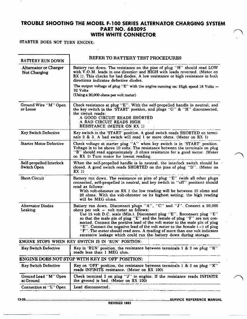
TROUBLE SHOOTING-THE MODEL F-100 SERIES ALTERNATOR CHARGING SYSTEM PART NO. 683095
WITH WHITE CONNECTOR STARTER DOES NOT TURN ENGINE:
BATTERY RUN DOWN
Alternator or Charger Not Charging
Ground Wire “M” Open or Loose
Key Switch Defective
Starter Motor Defective
Self-propelled Interlock Switch Open
Short Circuit
Alternator Diodes Leaking
REFER TO BATTERY TEST PROCEDURES
Battery run down. The resistance on the pins of plug “H” should read LOW with V.O.M. leads in one direction and HIGH with leads reversed. (Meter on RX 1). This checks for bad diodes. A low resistance or high resistance in both directions indicates defective diodes.
(Using a 20,000 ohms per volt meter)
Check resistance at plug “E”. With the self-propelled handle in neutral, and the key switch in the ‘START’ position, and plugs “G” & “H” disconnected, the circuit reads:
A GOOD CIRCUIT READS SHORTED
RESISTANCE (METER ON RX 1) A BAD CIRCUIT READS HIGH
Key switch in the ‘START’ position. A good switch reads SHORTED on termi- nals 2 & 3. A bad switch will read 1 or more ohms. (Meter on RX 1)
Check voltage at starter plug “A” when key switch is in ‘START’ position. Voltage is to be above 10 volts. The resistance between the terminals on plug “B” should read approximately .3 ohms resistance for a good motor. (Meter on RX 1) Turn motor for lowest reading. When the self-propelled handle is in neutral, the interlock switch should be closed. A good switch reads SHORTED on the pins of plug “D”. (Meter on RX 1)
Battery run down. The resistance on pins of plug “E” (with all other plugs connected, self-propelled in neutral, and key switch in “off” position) should read as follows:
With volt-ohmeter on RX 1 the low reading will be between 15 ohms and 20 ohms. With the volt-ohmeter on ‘its highest setting, the high reading will be MEG ohms.
Battery run down. Disconnect plugs “A”, “C” and “J”. Connect a 20,000 ohms per volt volt meter as follows:
Use 15 volt D.C. scale (Min.). Disconnect plug “E”. Reconnect plug “E” so that the male pin of plug “E” and the female of plug “F” are not con- nected. Connect the positive lead of the volt meter to the male pin of plug “E”. Connect the negative lead of the volt meter to the female (-) of plug “F”. The meter should read zero. A reading of more than one volt indicates excessive leakage which could run the. battery down during storage.
ENGINE STOPS WHEN KEY SWITCH IS IN ‘RUN’ POSITION:. Key Switch Defective Key in ‘RUN’ position, the resistance between terminals 1 & 2 on plug “K”
reads less than 1 MEG ohm.
ENGINE DOES NOT STOP WITH KEY IN ‘OFF’ POSITION: 1 & 2 on plug “ K ”
resistance reads INFINITE
13-28 SERVICE REFERENCE MANUAL REVISED 1983
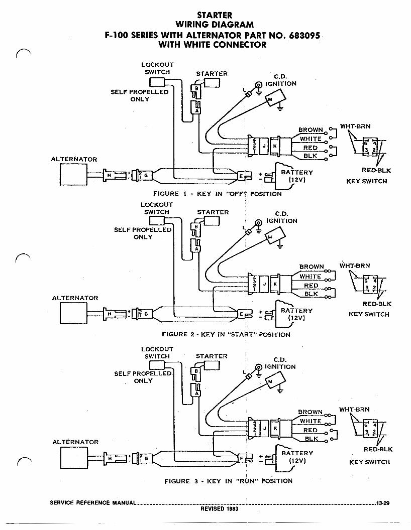
STARTER WIRING DIAGRAM
F-100 SERIES WITH ALTERNATOR PART NO. 683095 WITH WHITE CONNECTOR
.LOCKOUT SWITCH
ALTERNATOR
KEY SWITCH
FIGURE 1 KEY IN "OFF'” POSITION
LOCKOUT SWITCH STARTER C.D.
IGNITION
ONLY
ALTERNATOR
fIGURE 2 KEY IN "START" POSITION
ALTERNATOR
LOCKOUT SWITCH STARTER C.D.
ONLY
WHT-BRN
RED-BLK KEY SWITCH
WHT-BRN
RED-BLK
KEY SWITCH
SERVICE REFERENCE MANUAL 13-29 REVISED 1983

TROUBLE SHOOTING THE MODEL F-100 SERIES ALTERNATOR CHARGING SYSTEM PART NO. 6,83092
WITH BLACK CONNECTOR STARTER DOES NOT TURN ENGINE:
BATTERY RUN DOWN Alternator or Charger Not Charging
Ground Wire “M” Open or Loose
Key Switch Defective
Starter Motor Defective
Self-propelled Interlock Switch Open
Short Circuit
Alternator Diodes Leaking
ENGINE STOPS WHEN
REFER TO BATTERY TEST PROCEDURES
Battery run down. The resistance on the’ pins of plug “H” should read LOW with V.O.M. leads in one direction and HIGH with leads reversed. (Meter on RX 1). This checks for bad diodes. A low resistance or high resistance in both directions indicates defective diodes. The output voltage of plug “E” with the engine running on: High speed 18 Volts 32 Volts (Using a 20,000 ohms per volt meter)
Check resistance at plug “E”. With the self-propelled handle in neutral, and the key switch in the ‘START’ position, and plugs “G” & “H” disconnected, the circuit reads:
A GOOD CIRCUIT READS SHORTED A BAD CIRCUIT READS HIGH RESISTANCE (METER ON RX 1)
Key switch in the ‘START’ position. A good switch reads SHORTED on termi- nals 2 & 3. A bad switch will read 1 or more ohms. (Meter on RX 1) Check voltage at starter plug “A” when key switch is in ‘START’ position. Voltage is to be above 10 volts. The resistance between the terminals on plug “B” should read approximately .3 ohms resistance for a good motor. (Meter on RX 1) Turn motor for lowest reading. When the self-propelled handle is in neutral, the interlock switch should be closed. A good switch reads SHORTED on the pins of plug “D”. (Meter on RX 1)
Battery run down. The resistance on pins of plug “E” (with all other plugs connected, self-propelled in neutral, and key switch in “off” position) should read as follows:
With volt-ohmeter on RX 1 the low reading will be between 15 ohms and 20 ohms. With the volt-ohmeter on its highest setting, the high reading will be MEG ohms.
Battery run down. Disconnect plugs “A”, “C” and “J”. Connect a 20,000 ohms per volt volt meter as follows:
Use 15 volt D.C. scale (Min.). Disconnect plug “E”. Reconnect plug “E” so that the male pin of plug “E” and the female of plug “F” are not con- nected. Connect the positive lead of the volt meter to the male pin of plug “E”. Connect the negative lead of the volt meter to the female (-) of plug “F”. The meter should read zero. A reading of more than one volt indicates excessive leakage which could run the. battery down during storage.
KEY SWITCH IS IN ‘RUN’ POSITION: Key Switch Defective Key in ‘RUN’ position, the resistance between terminals 1 & 2 on plug “K”
reads less than 1 MEG ohm. I ENGINE DOES NOT STOP WITH KEY IN ‘OFF’ POSITION:
1 & 2 on plug “K”
resistance reads INFINITE at Ground
13-30 SERVICE REFERENCE MANUAL REVISED 1983
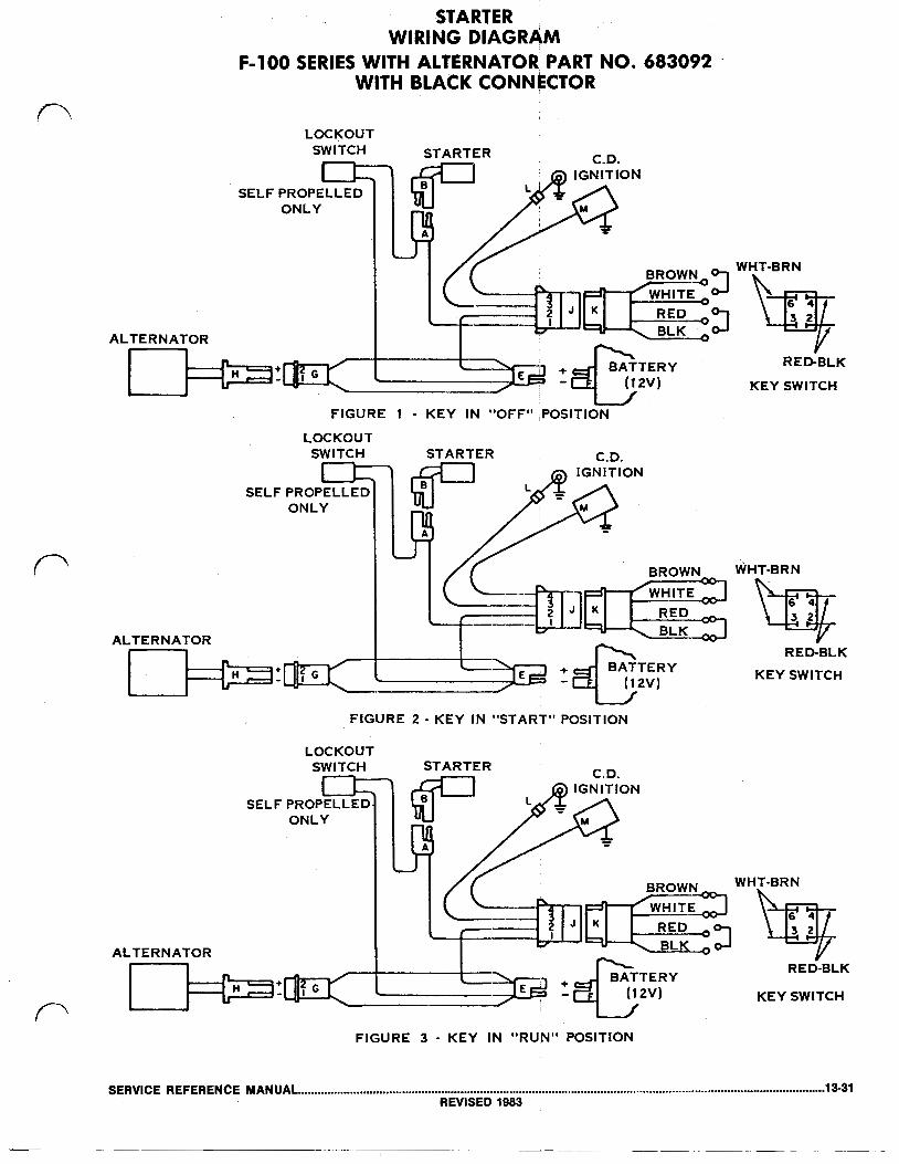
STARTER WIRING DIAGRAM
WITH BLACK CONNECTOR F-100 SERIES WITH ALTERNATOR, PART NO. 683092
ALTERNATOR
LOCKOUT SWITCH STARTER
C.D.
SELF
ALTERNATOR
FIGURE 1 - KEY IN "OFF" ,POSITION
LOCKOUT SWITCH STARTER C.D.
ONLY
I BROWN
ALTERNATOR BLK
FIGURE 2 KEY IN “START” POSITION
LOCKOUT SWITCH STARTER
WHT-BRN
RED-BLK
KEY SWITCH
WHT-BRN
RED-BLK KEY SWITCH
C.D.
WHT-BRN
ALTERNATOR RED-BLK
KEY SWITCH
FIGURE 3 KEY IN "RUN" POSITION
SERVICE REFERENCE MANUAL 13-31 REVISED 1983