alternative articulation systems in cable-stayed …
TRANSCRIPT

ALTERNATIVE ARTICULATION SYSTEMS IN
CABLE-STAYED BRIDGES
A DISSERTATION
Submitted in partial fulfilment of the requirements for the award of the degree
of MASTER OF ENGINEERING
in CIVIL ENGINEERING
(With Specialization in Structural Engineering)..... ...• --.)EtKk.. -,'-.. AC k....4.4;;;...
: 4t. ' -218031 # \ .*. k
Acc. N • 1 '.
\ ;
Date? t ..5.21 6E) ..,.,,, .,...,), ,,..„ v\ ..„4-/
MANOJ KUMAR GUPTA,ri."1.-IL
DEPARTMENT OF CIVIL ENGINEERING UNIVERSITY OF ROORKEE
ROORKEE — 247 667 (INDIA)
MARCH, 1998
By

CANDIDATE'S DECLARATION
I hereby certify that the work which is being presented in the dissertation
entitled "ALTERNATIVE ARTICULATION SYSTEMS IN CABLE-STAYED
BRIDGES" in partial fulfilment of the requirements for the award of the degree of
MASTER OF ENGINEERING in Civil Engineering with specialization in STRUCTURAL
ENGINEERING submitted in the Department of Civil Engineering , University of Roorkee,
Roorkee, is an authentic record of my own work carried out for a period of _7. month
(From August I99qto March 1990 under the supervision and guidance of Dr. Krishen
Kumar and Dr. Preen Krishna, both Professors in Department of Civil Engineering,
University of Roorkee, Roorkee (India).
The matter embodied in this dissertation has not been submitted by me for any other
degree or diploma.
Dated : March 1997 (MANOJ KUMAR GUPTA)
PLACE : Roorkee
This is to certify that. the above
best of my knowledge.
(Dr. KRISHEN KUMAR) Professor Structural Engineering Section Department of Civil Engineering University of Roorkee Roorkee - 247 667 (U.P.), India
statement made by the candidate is correct to the
(Dr. PREM KRISHNA) Professor Structural Engineering Section Department of Civil Engineering University of Roorkee Roorkee - 247 667 (U.P.), India
(i)

ACKNOWLEDGEMENT
First and foremost, I wish to express my deep sense of gratitude to Dr. Krishen
Kumar and Dr. Prem Krishna, both Professors in Department of Civil Engineering,
University of Roorkee, Roorkee for their valuable guidance, suggestions and continuous
encouragement at every stage in the preparation of this dissertation . The immense care
taken by Prof. Krishen Kumar in going through the manuscript and critical suggestions
tOr its improvement is gratefully acknowledged.
I express my deep indebtedness to my parents for their constant encouragement and
blessing for accomplishing this higher academic goal of my life. c
Finally, I bow before The Almighty God for giving me the strength of mind to
complete the work in time.
- • III■11/8=1"
(MANOJ KUMAR GUPTA)

ABSTRACT
The inherent. many-fold advantages associated with a modern day cable-stayed
bridge are being realized increasingly by the design and practising engineers in the
field of bridge engineering world over. Analytical studies and design of cable-stayed
bridges for static and dynamic loads have been carried out by many investigators.
Different parameters have been taken by them to find out the best possible
design. One of them is the various alternative articulations at the supports.
In the present work the analysis of the proposed 4-lane cable stayed bridge at.
NAINI, ALLFIABAD has been done taking four different articulations at the supports, using
STAAD3 general purpose engineering software package. The results obtained are the
horizontal shears at the top of piers and pylons, forces in cables and in the deck, for
the four different articulations alternatives at the supports.

LIST OF FIGURES
No. Description
2.1,2.2,2.3 Fundamental load bearing elements
Page No.
37
2.4 Transverse cable arrangement 38
2.5 Longitudinal Cable arrangements 39
2.6 Matrix of longitudinal configurations 39
2.7 Various types of stay cables 40
2.8 Typical Saddle 41
2.9 Alternate tower types 42
2.10 Second Hooghly Bridge at Calcutta 43
3.1 Various articulations at the supports • 44
4.1 Cable-stayed Bridge, Naini-Member Numbers 45
4.2 Cable-stayed Bridge, Naini-Member Numbers 46
4.3 Cable-stayed Bridge, Naini-Joint Numbers 47
4.4 Cable-stayed Bridge, Naini-Joint. Numbers 48
4.5 Sections at Different Levels 49
4.6 Longitudinal Selection in main and side span 50
4.7 Typical details of Pylons 51
4.8 Details of anchorage of cable stay 52
4.9 Pylon-Member Numbers 53
4.10 Pylon-Joint Numbers 54
(iv)

LIST OF TABLES No.
1(a),1(b
1(c)
Description
Some Important Small and Medium Span Structures.
Page No.
4.1 Horizontal earthquake motion in longitudinal direction of bridge 20
(response spectrum method).
4.2 Horizontal earthquake motion in transverse direction of bridge. 20
4.3 Horizontal shears (in kn) in piers and pylons in the direction
of the earthquake motion (seismic coefficient method).
30
4.4. Horizontal earthquake motion in transverse direction of bridge. 30
4.5 Forces in some typical cables due to Seismic Load. 31
4.6 Forces in Cable due to dead and live loads. 32
4.7 Forces in some typical deck members. 33
(v)

CONTENTS Page No.
CANDIDATE'S DECLARATION (i) ACKNOWLEDGEMENT ABSTRACT (iii) LIST OF FIGURES & TABLES (iv-v)
CHAPTER - I INTRODUCTION
1
.1 General
1.2 Objective of the Literature 3
CHAPTER - 2 REVIEW OF LITERATURE
4
2.1 General
4
2.2 Cable Systems 5
2.3 Types of Cable 7
2.4 Anchorages 9
2.5 Connections II
2.6 Saddles 12
2.7 Towers or Pylons 13
2.8 Energy Dissipation Devices 14
2.9 Indian Economic of Cable-Stayed Bridges 14
2.10 Details of Cable Stayed Bridges in India 15
CHAPTER - 3 ANALYSIS USING SOFTWARE "STAAD-III"
17
3. I General
17
3.2 Input Data 17
(vi)

CHAPTER - 4 RESULTS AND DISCUSSION
22
4.1 Bridge Statistics
4.2 Structural Idealization for Analysis 22
4.3 Material Properties and Cross-Section 23
4.4 Seismic Load for Analysis 24
4.5 Computation of Elastic Soil Stiffness for Pylons and Piers 25
4.6 Alternative Articulations at the Supports 27
4.7 Method of Analysis 27
4.8 Comparative Study of Horizontal Shears at piers 27
and Pylons in the Direction of Earthquake Motion
4.9 Analysis of Cable Forces clue to Seismic Load
31
4.10 Analysis of Deck Forces clue to Seismic Load 33
CHAPTER 5 CONCLUSION 35
5.1 General 35
5.2 Scope for Future Work 36
FIGURES 37-54
REFERENCES 55-56
APPENDIX A 57-59

CHAPTER - 1
INTRODUCTION
1.1 GENERAL
The subject of cable stayed bridges is comparatively new on the Indian bridge
building scenario. From the considerations of navigability on the rivers or seas bridges
with spans longer than 150m are seldom required in India. However, for some of our
mighty rivers with alluvium strata and acute problems of scour, foundation construction
becomes difficult and cost-prohibitive. For such cases and also for sites where long
span requirement is dictated by hydraulic considerations, construction of cable stayed
bridges with main span of the order of 250 in and above might become economically viable.
The first one - a pedestrion bridge at ROORKEE, U.P., India, having been completed in
1987 and the first major cable-stayed bridge in the country has been constructed over
river Hooghly at Calcutta having a central span of 457m. The necessary capabilities and
know-how exist within the country for design and construction of cable stayed bridges.
The recent increase in the range of aplication of cable stayed structure is closely
related with the development of high capacity stay-cables with reliable oncharges, made
of advanced construction materials and based on computer aided design. Also the
aesthetically most satisfactory appearance of a great number of cable stayed structures
in various parts of the world contributed to the wide acceptance of this type of
construction. Some of the most important small and medium span structures built to
date are shown in Table la, lb, lc in Appendix A The scope of applicatiOn of cable stayed
structure embraces:
Large railway and highway bridges with main spans from about 100m to 500m,
1

closing the gap between free cantilevering construction and suspension bridges.
Sky-scraper communication towers, large chimneys, antennas and wind power
stations.-
Large tent roofs grand stands, stadiums, light weight wide span strctures
Structures of smaller size such as pedestrian bridges, parking decks suspension
and hanger roofs.
Among these applications, long span cable-stayed bridges can be considered the most
spectacular structures. The basic concept is elegantly simple in that evenly spaced
supports of the bridge deck, which are provided by means of inclined tendons are tied
hack to pylons (towers). This allows long spans of slender bridge deck free of
intermediate columns. The most suitable construction procedure is the balanced
cantilevering method, whereby each and every second segment is suspended from one or a
pair of stay cables, while construction is starting from pylon towards the midspans.
Cable-stayed bridges can be constructed equally well in steel or concrete or both
materials combined.
There are an increasing number of cable-stayed bridges, recently completed and
currently under construction throughout the world. The increasing popularity of this
type of structure among structural engineers all over the world can be attributed to the
following possible reasons:-
(a) Appealing aesthetics
(b) The full and efficient utilization of structural materials particularly the
cables
(c) The increased stiffness over suspension bridges
(d) The efficient and fast mode of construction.
(e) The relatively small size of substructure
(f) Low maintenance cost.
2

(g) Lower initial cost.
1.2 OBJECTIVE OF THE STUDY :
The aim of the present study is to analyse a cable-stayed bridge with different
articulation systems for earthquake forces. The study tries to identity the best
alternative articulation conditions at deck support condition so as to get an optimum
value of the forces in the cables and also in other parts of the cable-stayed bridge
that is pylons, foundations due to seismic forces.
To establish a systematic procedure, analysis has been done for the proposed Naini
bridge over river Yamuna at Allahabad. •
3

CHAPTER - 2
REVIEW OF LITERATURE
2.1 GENERAL :
The basic load bearing elements of a cable-stayed bridge are cables, deck and
pylons. The interaction between the different parts is, in fact, very pronounced and it
is thus necessary to take them into account. Each of the three fundamental load bearing
elements contribute in a definite way to the structural behaviour of the whole. Three
cases of design approach are shown in Fig. 2.1, 2.2, 2.3, illustrating the inside range
of possible load bearing systems and the great. freedom of choice offered by the cable
stayed bridges.
The limit design shown in Fig. 2.1 contains a very stiff deck. It was adopted at
the start of modern development of cable-stayed bridges. Generally, a reduced number of
stays act as elastic intermediate supports in areas where it is not possible to provide
piers. The pylons are slender, since they are subjected to relatively small bending
moments.
• Limit design shown in Fig. 2.2 is characterised by very stiff pylons which must
take up the longitudinal moments due to live loads. The deck, in contrast is only
subjected to moderate moments, particularly if the cables are not spaced too for apart.
The result is a slender section, the minimum dimensions of which are governed by
transverse bending and direct forces. This solution is most suitable for multi-span
bridges.
Limit design shown in Fig.2.3 introduces the stays themselves as the determining
stabilizing elements of the structure. In order that the back-stay cables (which play a
major role in this case) shall not completely slacken off under live loads, the length
4

of side spans must be less than half the centre span. The resulting imbalance
introduces, under the permanent loads, major tensile forces in these cables. The use of
counter weights or tension piers is thus essential. This design leads to relatively
slender pylons and deck.
2.2. CABLE SYSTEMS :
2.2.1 There are five transverse arrangements of cables usually employed as shown in
the Fig.2.4. These are (a) single plane-vertical (b) single plane-vertical/lateral (c)
Double plane-vertical (d) double plane-sloping (e) double plane v-shaped.
Single plane system :
The single plane cable arrrangement is generally used with a divided road-way deck
with the cable passing through the median strip and anchored below the roadway. This
arrangement is not only economical but aesthetically pleasing as well.Very little width
of deck is required to accommodate the cables. Here, the possible disadvantage is the
fact that a relatively large concentrated cable force is transferred to the main super
structure girder, thereby requiring a larger connection and girder to support the cable
force.
Additional reinforcement requirement and stiffening of the deck web plates and
bottom flange will be normally required in order to distribute the concentrated load
uniformely throughout the cross sections of the superstructure members. In this
arrangement cables support vertical or gravity loads only. The torsional force that
develops because of asymmetric vechicular loading or wind forces must be resisted by a
torsionally stiff box girder in order to transmit the unbalanced forces to the piers.
Other provisions may he provided to resist the torsional force developed in the
superstructure.
5

Double plane system :
This system consists of the cable in two vertical planes situated at the two edges
of the deck. Sometimes, oblique cable arragement may also be located on the outside of
A-type frames. In this system, anchorages may be located either on the outside of the
deck structure or within the limits of the deck roadway. With the cable anchorages on
the outside of the deck an advantage is gained because, no portion of the deck roadway
is required for connection fittings No doubt, disadvantage lies in the fact that
additional reinforcement may be required to transmit the ecentric cable loading of shear
and moment into the main girders of superstructure. The additional width of the roadway,
required to accommodate the anchorage, may result in the increased cost.
Three plane system :
It consists of three vertical planes of cables, one in the median strip and the
other two on the exterior edges of the bridge deck. The concept is appropriate for the
use in urban areas where it may be necesseary to include mass transit lanes or special
bus lanes as well as three or four vehicular lanes in each direction.
2.2.2 Longitudinal cable arrangement :
There are four cable configurations in general used throughout the world today as
shown in Fig. 2.5. These basic systems are referred to as radiating, harp. fan and star
systems.
In the radiating or the converging system cables intersect or meet at a common
point at the top of the tower. In harp type, the cables are parallel and equidistant
from each other, the required number of cables are spaced uniformely along the tower
height and as a result, also connected to the roadway superstructure with equal spacing.
In fan type the cables emanate from the top of the tower with equal spacing and
6

connected with equal spacing along the superstructure. In star arrangement, cables
intersect the pylon at different heights and then converge on each side of the tower to
intersect the roadway structure at a common point.
The selection of cable configuration and number of cables is dependent on the
length of span, type of loadings, number of roadway lane, height of tower, economy and
the designer's individual sense of proportion and aesthetics.
Lesser number of cables result in the complicated and heavy anchorage system as
compared to larger number of cable system where the ordinary anchorages solve the
problem and the forces are more uniformely distributed throughout the deck structure
without major reinforcement to the existing girders and floor beams.
In radiating arrangement maximum angle of inclination to the bridge girder is
achieved and hence the cables are in an optimum position to support the gravity dead and
live loads. A summary of various cable arrangements is shown in Fig.2.6.
2.3. TYPES OF CABLES :
The suspension systems of bridges at present in service fall into the following
categories. These are shown in figure 2.7.
a. Parallel bar cables
b. Parallel wire cables
c. Stranded cables
d. Locked coil cables
The choice of these types depends on the mechanical properties required such as
modulus of elaSticity, ultimate tensile strength, durability etc.
a. Parallel wire cables :
These are formed if steel rods or bars, parallel to each other and in metal ducts
7

kept in position by polyethylene spacers. The bars can slide in longitudinal direction
which simplifies the process of tensioning them individually. Injection of cement grout,
carried out after erection makes sure that the duct plays its part in resisting the •
stresses due to live loads. if length is 15-20 m, continuity then has to be provided by
the use of couplers, which considerably reduces the fatigue strength of the stay.
b. Parallel wire cables : In the 19th century, J Roebling developed a technique of spinning parabolic cables
for suspension bridges. It consits of drawing between two towers a group of small
diameter, mild steel wires, using a carriage running on those members already stretched
across.
Today, they are of high strength drawn steel and are placed in metal or
polyethylene ducts. The ducts are generally injected with a cement grout after erection.
Their fatigue strength is satisfactory mainly because of their good mechanical
properties.
c. Stranded cables :
These have been recently used, mainly for economic reasons. Each strand consists
of seven twisted wires, with an external diameter of 12.7 mm or 17.78 mm. When the
cables are stressed, the lateral stresses which are produced have a bad effect on their
fatigue resistance. Also their sensitivity of corrosion is increased since for a given
cross-sectional area, the perimeter of a section made up of many wires is greater than
that of a single circular member. However techincal progress associated with effective
protection measures has made it possible to overcome these problems in a satisfactary
manner.
8

d. Locked - coil cables :
In these types of cables the wires are arranged in successive layers, wound around
a central core which consists of circular parallel wires. On the outside, elongated S-
sections are used and in view of the extent of their overlapping, these form an envelope
which is more or less watertight (Hence the name locked coil cable). This effect is even
more emphasised by the action of the lateral stresses produced during tensioning. Units
are thus obtained which consist of eight or nine layers of 4.7 mm dia wires.
The advantages of locked-coil cables lie in the ease of placing, the economy arising
from the fact that ducts and grouting are unnecessary, the reduced anchorage space and
the great flexibility which makes it possible to use guiding saddles at the pylons
instead of intermediate anchorages.
2.4. ANCHORAGES :
Cable stays have end anchorages by which they can be connected to other parts of a
structure. These fittings vary in shape, size and weight depending upon the diameter of
the cables to which they are attached. The anchorages should lie designed, manufactured
and attached to the cables so that they are capable of transferring the breaking
strength of the cable without exceeding the yield strength of the fittings.
An important criteria for cable stay end anchorages is that they should he
accessible for inspection and retensioning during the life of structure. Some of the
anchorage systems are enumerated in brief as below.
2.4.1 The swaged and the zinc-poured type :
The swaged sockets are used for small diameters of strands (12-66 mm.) and (10-50
mm.) for rope cables. The poured zinc type of fitting had been an accepted method for
the large strand sizes. Cable diameter range from 12 to 100mm. for strand and 10 to 100
9

mm for rope. The limitation with zinc poured sockets is their low fatigue strength and
it is highly temperature susceptible.
2.4.2 Ain Anchorages :
It is high Amplitude (Hi Am) anchorage. It can develop full fatigue capacity of the
element wires and is not influenced by the same temperatures that are developed in zinc
poured sockets.
2.4.3 VSL Anchorages :
VSL anchorages are an adaption of the VSL post tensioning systems used in
prestressed concrete construction. Its main characteristic is the cable stay which is
composed of parallel 7 wire prestressing strands. It is a modular system that enables
any desired stay to be fabricated from standard units.
2.4.4 Stronghold Anchorages :
Anchorages used in conventional prestressed concrete construction are designed to
resist cyclic loads directly related to the maximum allowable tendon forces. Such
criteria are inadequate for cable stay structures. Specifications governing cable- stay
bridges require a higher cyclic performance both in amplitude and frequency. The fact
that mechanical anchorages are not able to meet these rigid requirements led to the
development of an anchorage known as type B stronghold anchorage.
2.4.5 Fressinet anchorages :
It consists of a trumpet, which accommodates the flare of the strands within the
anchorage, a heavy steel pipe trumpet extension, a bearing plate; an anchorage block;
and epoxy cement, or other compound grout filler material.
10

2.5 CONNECTIONS :
The cable stays are either individually anchored at the top of pylon or pass
through the pylon on saddles. The saddle if used may be fixed to prevent translation
with respect to pylons or it is supported on rollers to allow translation.
If the structural intent is to fix the saddle, then the friction between the
stays must be sufficient to overcome the net horizontal force of the stay on each side
of the pylon. If the friction is not sufficient to overcome this force then the stays
must be clamped to the saddle to provide increased frictional capacity. Where a saddle
is on rollers and allowed to translate, the translation is a self equilibrium mechanism
that equalizes the stress in the stay on either side of the pylon.
The advantage of a saddle is that it automatically reduces the number of
expensive stay anchorages by one half. However, the disadvantages are that the stay
being continuous must be sized for the larger forces coming from one side of the pylon
and there is an inefficiency in meterial usage in the stay on the opposite side of the
pylon.
2.5.1.Connection of Cable Stays to Pylon :
Basically, cable stays are either individually anchored as the top of the pylon or
pass through the pylon on saddles. Where saddles are used there are two options : the
saddle is fixed to prevent translation with respect to the pylon. or it is supported on
rollers to allow translation. If the structural intent is to fix the saddle, them the
friction between the stays must be sufficient to overcome the net horizontal force of
the stay on each side of the pylon. If friction is not sufficient to overcome this force
then the stays must be clamped to the saddle to provide increased frictional capacity.
Where a saddle is on rollers and allowed to translate, the translation is a self-
equilibrium mechanism that equalize s the stress in the stay on either side of the
11

pylon. The advantage of a saddle is that it automatically reduces the number of
expensive stay anchorages by one-half. However, the disadvantages are that the stay,
being continuous, must be sized for the larger force coming from one side of the pylon,
and there an inefficiency in material usage in the stay on the opposite side of the
pylon. Current criteria requires that a stay by replicable, for any unforseen event, and
thus requires that the continuous stay be replaced from girder anchorage, through the
pylon, and to the opposite corresponding girder anchorage.
2.5.2 Connection of cable stays to girder :
Cable stay connections require careful consideration and analysis with respect to
the distribution of the stay force into the superstructure girder.
There are basically three configurations
(i) A longitudinal spine box coinciding with the plane of stays in the case of a
single plane of stays.
(ii) Longituinal edge girders in case of a double plane of stays
(iii) In some instances, for the double plane system, the longitudinal girders are not
in the same plane as the cables and transverse anchorage girders must be provided
to transfer the cable force to the primary longutudinal girders.
2.6 SADDLES :
Saddles are grooved cable supports designed with due consideration of the bearing
pressures, band radia , and groove diameters . All surfaces in contact with the cables
should be smooth to aviod nicks in the wires. To avoid stress concentration and minimize
excessive bending at the end of grooves, a generous contour is provided , which
eliminates cable chafing.
In order to ensure proper seating of the individual cables or strands, a zinc or
12

aluminium filler may be used in the groove . These soft matertials will flow plastically
and provide a smooth surface for the cables to rest upon.
The radius of the saddle grooves must provide a contact area between cable and
saddle that results in permissible bearing pressures on the cables and the saddle. The
radius must be selected to maintain the bending stresses in the outer fibers of the
cables within allowable limits. When movment of the saddle is not provided in the design
and construction , the unbalanced forces at the saddle must be resisted by friction and
shear on the plates between layers of strands or cables. Additional clamping force may
be provided by a clamp over the top of the cables that holds them in a fixed position.
A typical saddle is shown in Fig. 2.8.
2.7. TOWERS OR PYLONS :
The cable towers are often referred to as pylons. Similar to the cable systems ,
the towers are of many shapes and varities to accomodate different cable arrangements,
bridge site conditions , design requirements, aesthetics and economics.
In their simplest form, the towers may be a single cantilever to support a
single-plane arrangement of cables or two cantilever towers to support the double plane
cable system. The towers may be hinged or fixed at the base depending upon the magnitude
of vertical loads and distribution of cable forces along the tower height.
Other forms suitable for cable-stayed bridges are the portal form and A -frame
types. The decision to use a fixed or hinged base for the tower connection either to the
pier or the superstructure must be based on the magnitude and relationship of the
vertical and horizontal forces acting on the tower. A fixed base induces large bending
moments at the base of the tower whereas a hinged base does not and may be preferred,
However, the increased rigidity of the total structure resulting from the fixed base of
the towers may offset the disadvantage of the large bending moments. Another
13

consideration is that a fixed base may be more practical to erect and may be less costly
than inserting a heavy pinned bearing which requirs the tower to be externally supported
untill the cables are connected. The selection of a specific type of tower entails
consideration of sereral factors. For example, when a large clearance is required below
the superstructure, the A-frame has a decided disadvantage as larger pier width is
required to accommodate the legs of the frames in some instances a modified A-frame
with a short top cross member may be the best solution considering all - the factors
involved.
Some of the alternative tower-types are shown in Fig 2.9 (a) (b) & (c).
The towers are normally constructed of cellular section and are fabricated of
structural or reinforced concrete. The concrete towers may be built where the steel is
in short supply.The trend recently has been towards concrete towers with a structural
steel super structure deck because of the inherent qualities of concrete in compression.
2.8. ENERGY DISSIPATION DEVICES :
These are the devices which arc provided on the supports of deck and permit slow
long term movenents between the structures with negligible resistance yet is capable, of
acting as a rigid link between the structure, dissipating the energy due to short.
duration shock or impact forces. Recentely some viscous materials like, silicon putty
are being used which leave onluy a small part of the incoming shock force to be resisted
by the bridge structure.ure.
2.9 INDIAN ECONOMICS OF CABLE-STAYED BRIDGES (Ref-6) :
A clear picture regarding the interrelationship and sensitivity of parameter
influencing the economic viability of constructing cable-stayed bridges in a, developing
country like INDIA is expected to emerge after a few such projects are completed.
14

It is observed that price ratio of steel to concrete in Indian conditions largely
infenences the choice in favour of concrete cable-stayed bridges. The construction of
steel box gerder with orthotropic deck in India faces certain problems. As a result,
cable stayed bridges with either all concrete or composite construction are being
currently favoured. The present unit prices of the major construction materials
manufactured in India are indicated below.
CONSTRUCTION MATERIAL Cost in Rs. per Tonne
(a) portland cement
(b) Structural mild steel
(c) Torsteel Reinforecment
(d) Prestressing wire
(e) Prestressing strand
(t) Stay cables (Parallel wire)
3,000
25,000
20,000
60,000
80,000
300,000
2.10. DETAILS OF SECOND HOOGHLY CABLE-STAYED BRIDGES
AT CALCUTTA, INDIA (Ref- 4) :
1. Second Hooghly Bridge at calcutta (Fig 2.10) :
General arrangement and salient features of this bridge is furnished in Fig. 2.10.
The pylon and girders are of rivetted steel construction and deck is of 230 mm thick RC
slab composite with girders.
Some of the features of the stay-cable used are given below:
Total quantity of stay cables: 1250 tonnes
MaximUm design load in cable: 7670 KN (in back stays)
Maximum stressing force in cable : 5644 KN
15

Maximum outer dia of HDPE tube : 200 mm
Maximum no of wires per cable:277 of dia 7 mm
Maximum size of forced Hi-Am socket : 360 mm dia & 650 mm long.
I6

CHAPTER - 3
ANALYSIS USING SOFTWARE `STAAD - III'
3.1 GENERAL :
The analysis of the cable stayed portion of the Naini bridge at Allahabad is
carried out using the STAAD 3 general purpose structural Engineering Software. The
analysis of the 3-Dimensional space structure has been carried out using the matrix
displacement method for the various alternative articulations at the supports. Dynamic
response for the seismic loading has been obtained by the Response spectrum analysis.
Response spectrum has been used and modal responses have been combined using square root
of sum of squares (SRSS) method to obtain the resultant response .
3.2 INPUT DATA :
The preparation of input data is done in the following sequence. The structure is
sketched and joints are numbered in such a way that members having same properties are
numbered in sequence so as to enable easy interpretation of the output.
The input data and program using STAAD 3 commands is attached here for the case of
deck connected only to one pier (P-I5) in longitudinal-direction, with rollers at pylons
and other piers.
The articulation conditions that are taken for the present study are shown in
figure 3.1.
17

1. STAAD SPACE CABLE STAYED DRIDGE--YANUNA
2. * DECK CONNECTED ONLY TO ONE PIER (P-15) IN X- DIRN 3. * WITH ROLLERS AT PYLONS AND OTHER PIERS 4. * R.O. T11 X- is V oimi 5. INPUT WIDTH 72
' 6. UNIT METER KNS
7. JOINT COORDINATES
8. 1 0. 0. 18.2; 2 30. 0. 3.8.2; 3 50. 0. 18.2; 4 60. 0. 18.2; 5 70. 0. 10.2 9, 6'80. 0. 10.2; 7 90. 0. 10.2; U 100. U. 10.2; 9 110. 0. 18.2 10. 10 120. 0. 18.2; 11 130. 0. 10.2/ 12 0. 10.2/ 13 1DO.
1.40. U. 10.2 11. 14 160. 0. 10.2; 15 170. 0. 3.0.2; 16 3i10, U. 10.2 0. 10.21 1'! 190 , 12, 10 200. U. 18.2; 19 210. 0. 10.2; 20 220. 0. 0. 10.2; 21 230. 10.2 13. 22 240. 0. 18.2; 23 250, 0. 18.2; 24 260. 0, 0. 10.2; 25 270. 10.2 14. 26 200. 0. 10.2; 27 290, 0. 10.2; 28 300. 0. 0. 18.2; 29 310. 18.2 15. 30 320. 0. 18.2; 31 330. 0. 18.2; 32 0. 18.2; 33 350. 18.2
340. 0. 16. 34 360. 0. 18.2; 35 370 0. 18.2; 36 380. 0. 0. 18.2; 37 390. 18.7. 17. 30 400. 0. 18.2; 40 39 410. 0. 18.2; 420. 0. 18.2; 41 430, 0. 10.2 10, 42 440, 0. 10.2; 44 43 450. 0. 10.2; 460. 0. 10.2; 45 470. 0. 10.2 19.'46 480. 0. 18.2; 48 47 490; 0, 18.2; 500, 0. 18.2; 49 510. 0. 10.2 20. 50 520. 0. 10.2; 52 51 530. 0. 10.2; 540. 0. 18.2; 53 550. 0. 10.2 '21. 560. 0. 18.2; 54 55 580. 0. 18.2; 56 610. 0. 10.2; 57 0. 0. 0. 22. 30, 0. 0.; 59 58 50. 0. 0.; 60 60. 0. 0.; 61 70..0, 0.; 62 00. 0. 0. 23. 90. 0. 0.; 64 63 100. 0. 0.; 65 110. 0. 0.; 66,120, 0. 0.; 67 130 , 0. 0. 24, 140, 0. 0.; G9 150. 68 0. 0.; 70 160. 0, 0,; 71 170. 0 , 0 , 25. 180. 0. 0.; 73 190. 72 0. 0.; 74 200. 0. 0.; 75 210. 0. 0.
76 0 , 0.; 78 240. 0. 0.; 79 250. 0. 0. 26, 220. 0. 0.; 77 230, 27. 260. 0. 0.; Al270. 00 0. 0.; 02 280. 0. 0.; 83 290. 0. 0. 28 300. 0. 0.; 85 310. 84 0. 0.; 86 320. 0. 0.; 87 330. 0. 0. 29. 88 340. 0. 0.; 89 350. 0. 0.; 90 360. 0. 0.; 91 370. 0. 0. 30, 92 280. 0, 0.; 93 390. 0. 0.; 94 400. 0. 0.; 95 410. 0. 0. 31. 96 420. 0. 0.; 97 430. 0. 0.; 98 440. 0. 0.; 99 450. 0. 0. 32: 100 460. 0. 0.; 101 470. 0. 0.; 102 480. 0. 0.; 103 490. 0. 0. 33. 104 500. 0. 0.; 105 510. 0. 0.; 106 520. 0. 0.; 107 530. 0, 0. 34. 108 540. 0, 0.; 109 550.'0, 0.; 110 560. 0. 0.; 111 1100. 0. 0, 35. 112 610. 0. 0.; 113 175. -29.9 15.6; 114 175. -2.9 24.1 36. 115 175. 22.1 21.15; 116 175. 47.1 18.2; 117 175. 50,6 10.2 37. 118 175. 53.6 18.2; 119 175. 56.6 18.2; 120 175. -2.9 18.2 38. 121 175. -2.9 0.; 122 175. -29.9 2.6; 123 175. -2.9 -5.9 39. 124 175. 22.1 -2.95; 125 175. 47.1 0. 40. 126 175. 50.6 0.; 127 175. 53.6 0. 41. 120 175. 56.6 0.; 129 175, 0. 18.2; 130 175. 0. 0.; 131 435. -29.9 15.6
18

CABLE STAYED BRIDGE--YAMUNA * DECK CONNECTED ONLY TO ONE PIER (P-15) IN 42, 132 435. -2.9 24.1; 133 435. 22.1 21.15; 134 435. 47.1 18.2 43. 135 435. 50.6 18.2; 136 435. 53.6 18.2; 137 435. 56.6 18.2 44. 138 435. -2.9 18.2; 139 435. -2.9 0.; :40 435. -29.9.2.6 45. 141 435. -2.9 -5.9; 142 435. 22.1 -2.95; 143 435. 47.1 0. 46. 144 435. 50.6 0..; 145 435. 53.6 0.; 146 435. 56.6 0. 47. 147 435. 0. 18.2; 148 435. 0. 0.; 149 -10. 0. 18.2; 151 10. 0. 18.2 48. 153 20. O. 18.2; 155 40. 0. 18.2; 157 570, 0. 18.2; 159 590 0. 18.2 49. 161 600. 0. 18.2; 163 620. 0. 18.2; 153 -10. 0. 0.; 152 10. 0. 0. 50. 154 20. 0. 0.; 156 40. 0. 0.; 158 570..0. 0.; 160 590. O. 0. 51. 162 600. 0. 0.; 164 620. 0. 0.; 165 173. -29.9 9.1 52. 166 175. -66.9 9.1; 167 435. -29.9 9.1; 168 435. -66.9 9.1 53. 169 0. -10.7 18.2; 170 0. -66.9 18.2; 171 0. -10.7 0. 54. 172 0. -66.9 0.; 173 60. -25.2 18.2; 174 60. -66.9 18.2 55. 175 60. -25.2 0.; 176 60. -66.9 0.; 171 550. -25.2 18.2 56. 178 550, -66.9 18.2; 179 550. -25.2 0.; 180 550. -66.9 0 57. 181 610. -25.2 18.2; 182 610. -66.9 1E.2; 183 610. -25.2 0. 58. 184 610. -66.9 0. 59. * COORDINATES OF DECK POINTS 60. * COORDINATES OF POINTS ON PYLON 61. MEMBER INCIDENCES 62. 1 1 101; 2 165 3; 3 3 4; 4 4 0; 5 5 6; 6 6 7 63. 7 7 8; 8 8 9; 9 9 10; 10 10 11 64. 11 11 12; 12 12 13; 13 13 14; 14 14 15; 15 15 129; 16 16 17; 17 17 18 65. 18 18 19; 19 19 20; 20 20 21; 21 21 22; 22 22 23; 23 23 24; 24 24 25 66. 25 25 26; 2626 27; 27 27 28; 28 28 29; 29 29 30; 30 30 31; 31 31 32 67. 32 32 33; 33 33 34; 34 34 35; 35 35 36; 36 36 37; 37 37 38; 38 38 39 68. 39 39 40; 40 40 41; 41 41 147; 42 42 43; 43 43 44; 44 44 45; 45 45 46 69. 46 46 47; 47 47'48; 48 48 49; 49 49 50; 50 50 51; 51 51 52; 52 52 53 70. 53 53 54; 54 54 157; 55 161 56 71. 56 57 152; 57 156 59; 58 59 60; 59 60 61 72. 60 61 62; 61 62 63; 62 63 64; 63 G4 65; 64 65 66; 65 66 67; 66 67 68 73. 67 68 69; 68 69 70; 69 70 71; 70 71 130; 71 72 73; 72 73 74; 73 74 75 74. 74 75 76; 75 76 77; 76 77 78; 77 78 79; 78 79 00; 79 00 81; 80 81 82 75. 81 82 83; 82 83 84; 83 84 85; 84 85 86; 85 86 87; 86 87 88; 87 88 89 76. 88 89 90; 89 90 91; 90 91 92; 91 92 93; 92 93 94; 93.94 95; 94 95 96 77. 95 96 97; 96 97 148; 97 98 99; 98 99 100; 99 100 101; 100 101 102 78. 101 102 103; 102 103 104/ 103 104 105; 104 105106; 105 106 107 79. 106 107 106; 107 108 109; 106 109 110; 109 110 150; 110 162 112 80. 111 1 57; 112 2 58; 113 3 59; 114 4 60; 115 5 61; 116 6 62; 117 7 63 81, 118 8 64; 119 9 65; 120 10 66; 121. 11 67; 122 12 68; 123 13 G9 82. 124 14 70; 125 15 71; 126 16 72; 127 17 73; 128 18 74; 129 19 75 83. 130 20 76; 131 21 77; 132 22 78; 133 23 79;. 134 24 80; 135 25 81 84. 136 26 82; 137 27 83; 138 28 84; 139 29 85; 140 30 86; 141 31 87 85. 142 32 88; 143 33 89; 144 34 90; 145 35 91; 146 36 92; 147 37 93 86. 148 38 94; 149 39 95; 150 40 96; 151 41 97; 152 42 98; 153 43 99 87. 154 44 100; 155 45 101; 156 46 102; 157 47 103; 158 48 104; 159 49 105 88. 160 50 106; 161 51 107; 162 52 108; 163 53 109; 164 54 110; 165 55 111 89. 166 56 112; 167 113 114; 168 114 115; 169 115 116; 170 116 117 90. 171 117 118; 172 118 119; 173 122 123; 174 123 124; 175 124 125 91. 176 125 126; 17.7 126 127; 178 127 128; 179 120 114; 18.0 121 120 92. 181 123 121; 182 130 129; 183 125 116; 184 119 3; 185 119 4; 186 119 5 93. 187 118 6; 188 118 7; 189 118 8; 190 117 9; 191 117 10; 192 117 11 94. 193 116 12; 194 116 13; 195 116 14; 196 116 15; 197 116 16; 198 116 17 95. 199 116 18; 200 116 19; 201 117 20; 202 117 21; 203 117 22; 204 110 23 96, 205 118 24; 206 118 25; 207 119 26; 208 119 27; 209 119 28; 210 128 59
97. 211 128 60; 212 120 61; 213 127 62; 214 127 63; 215 127 64; 216 126 65
19

CABLE STAYED BRIDGE--YAMUVA
* DECK CONNECTED ONLY TO ONE PIER (P-15) IN
98. 217 126 66; 218 126 67; 219 125 68; 220 125 69; 221 125 70; 222 125 71
99. 223 125 72; 224 125 73; 225 125 74; 226 125 75; 227 126 76; 228 126 77
100. 229 126 78; 230 127 79; 231 127 80; 232 127 81; 233 128 02; 234 120 83
101. 235 128 84; 236 120 129; 237 121 130; 238 131 132; 239 132 133
102. 240 133 134; 241 134 135; 242 135 136; 243 136 137; 244 140 141
103. 245 141 142; 246 142 143; 247 143 144; 248 144 143; 249 145 146
104. 250 138 .32; 251 139 138; 252 141 139;253 148 147 105. 254 143 134;255 138 147;256 139 148; 257 137 29 106, 250 137 30; 259 137 31; 260 136 32; 261 136 33; 262 136 34; 263 135 35 107. 264 135 36; 265 135 37; 266 134 38; 267 134 39; 268 134 40; 269 134 41 108. 270 134 42; 271 134 43; 272 134 44; 273 134 45; 274 135 46; 275 135 47 109. 276 135 48; 277 136 49; 278 136 50; 279 136 51; 280 137 52; 281 137 53 110. 282 137 54; 283 146 85; 284 146 86; 285 146 87; 286 145 88; 287 145 89 111. 288 145 90; 289 144 91; 290 144 92; 291 144 93; 292 143 94; 293 143 95 112. 294 143 96; 295 143 97; 296 143 98; 297 143 99; 2'98 143 100; 299 143 101 113. 300 144 102; 301 144 103; 302 144 104; 303 145 105; 304 145 106 114. 305 145 107; 306 146 108; 307 146 109; 308 146 110; 309 149 1 115. 310 151 153; 311 153 2; 312 2 155; 313 129 16; 314 147 42; 315 157 55 116. 316 55 159; 317 159 161; 318 56 163; 319 150 57; 320 152 154 117. 321 154 58; 322 58 156; 323 130 72; 324 148 98; 325 158 111 118. 326 111 160; 327 160 162; 328 112 164; 329 149 150; 330 151 152 119. 331 153 154; 332 155 156; 333 157 158; 334 159 160; 335 161 162 120. 336 163 164; 337 122 165; 338 165 113; 339 165 166 121. 340 140 167; 341 167 131; 342 167 168
122. 343 1 169; 344 57 171; 345 4 173; 346 60 175; 347 53 177; 348 109 179 123: 349 56 181; 350 112 183; 351 169 170; 352 171 172; 353 173 174 124. 354 175 176; 355 177 170; 35G 179 180; 357 181 182; 358 183 184 125. MEMBER PROPERTY INDIAN
12d. 1 TO 3 56 TO 58 PRI AX 7.938 IX 2.429 IY 489.7 IZ 7.49 127. 53 TO 55 108 TO 110 PRI AX 7.9 IX 2.4 IY 489.7 IZ 7.49 128. 309 TO 312 319 TO 322 PRI AK 7.930 IX 2.429 1Y 409.7 1Z 7,49 129. 315 TO 310 325 TO 328 PRI AX 7.9 IX 2 4 IY 489.7 IZ 7.49 130. 4 TO 52 59 TO 107 PRI AX 4.706 IX 0.475 IY 222.968 IZ 0.473 131. 313 314 323 324 PRI AX 4.706 IX 0.475"IY 222.968 IZ 0.473 132. 182 253 PRI AX 0.924 IX 0.363 IY 1E6 IZ 0.258 133. 111 114 163 166 PRI AX 9.268 IX 3.175 IY 1E6 IZ 10.792 134. 112 113 115 TO 162 329 TO 332 PRI AX 3.5 IX 0.09 IY 1E6 IZ 0.45 135. 164 165 333 TO 336 PRI AX 3.5 1X 0.09 1Y 1E6 IZ 0.45 136. 196 197 222 223 269 270 295 296 PRI AX 4.242E-3 137. 195 198 221 224 268 271 294 297 PRI AX 4.242E-3 138. 194 199 220 225 267 272 293 298 PRI AX 4.794E-3 139. 193 200 219 226 266 273 292 299 PRI AX 5.164E-3 140: 192 201 218 227 265 274 291 300 PRI AX 5.685E-3 141. 191 202 217 228 264 275 290 301 PRI AX 6.375E-3 142. 190 203 216 229 263 276 289 302 PRI AX 6.758E-3 143. 189 204 215 230 262 277 288 303 PRI AX 7.510E-3 144. 188 205 214 231 261 278 207 304 PRI AX 7.982E-3 145. 187 206 213 232 260 279 286 305 PRI AX 8.466E-3 146. 207 233 259 285 PRI AX 9.129E-3
147, 208 234 250 284 PRI AX 9.01UE-3 140. 209 235 257 203 PRI AX 10.187E-3 149. 186 212 280 306 PRI AX 10.187E-3 150. 185 211 281 307 PRI AX 10.187E-3 151. 184 210 282 308 PRI AX 10.736E-3 152. 167 173 238 244 PRI AX 12.63 IX 30.065 II 17.65 IZ 15.21 153. 168 169 174 175 PRI AX 7.15 IX 6.61 IY 6.293 IZ 2.887
20

CABLE STAYED BRIDGE--YAMUNA * DECK CONNECTED ONLY TO ONE PIER (P-15) IN
154. 239 240 245 24G PRI AX 7.15 1X 6.61 IY 6.293 IZ 2.884 155. 170 TO 172 176 TO 178 PRI AX 5.5 IX 3.966 IY 2.865 IZ 2.218 156. 241 TO 243 247 TO 249 PRI AX 5.5 IX 3.966 IY 2.865 IZ 2.218 157. 179 TO 181 250 TO 252 PRI AX 10.24 IX 27.41 IY 18.57 IZ 18.57 158. 183 254 PRI AX 8. IX 7.296 IY 2.667 IZ 10.67 159. 236 217 255 256 PRI AX 0.01 IX 1E-4 IY 1E-4 IZ 100. 160. 337 338 340 341 PRI AX 1E4 IX 1E6 IY 1E6 IZ 1E5
.161. 339 342 PRI AX 102.26 IX 5000. IY 3567. IZ 1116. 162. 343 TO 350 PRI AX 7.314 IX 8.599 TY 4.295 IZ ..304 163. 351 TO 358 PRI AX 31.61 IX 285.5 IY 142.75 IZ 142.75 164. MEMBER TRUSS 165. 184 TO 235 257 TO 308 166. MEMBER RELEASE 167. 343 344 START MX MY MZ 168. 345 TO 350 START FY MX MY MZ 169. 236 237 255 256 END FY MX MY MZ 170. CONSTANT 171. E 40304956. MEMB 1 TO 183 236 TO 256 309 TO 358 172. DENSITY 25. MEMB 1 TO 110 167 TO 183 236 TO 256 309 TO 328 173. DENSITY 25. MEMB 339 342 TO 358 174. DENSITY 0, MEMB 337 338 340 341 175. DENSITY 7.12 MEMB 112 113 115 TO 124 127 TO 150 153 TO 162 164 165 176. DENSITY 7.12 MEMO 329 TO 336 177. DENSITY 18.26 MEMB 111 114 163 166 178, DENSITY 25. MEMB 125 126 151 152 179. POISSON 0.15 MEMO 1 TO 183 23G TO 256 309 TU 358 180. E 1.600E8 MEMO 184 TO 235 257 TO 308 161.•DENSITY 78.43 MEMO 184 TO 235 257 TO 308 182. SUPPORT 183. 170 172 174 176 178 180 182 184 FIXED BUT KMX 13.2E7 KMZ 13,2E7 184. 166 168 FIXED BUT KMX 28.2E7 KMZ 15.E7 185. LOAD 1 SEISMIC LOAD SPECTRUM IN LONGITUDINAL DIRECTION 186. SELFWEIGHT X 1. 187. SELFWEIGHT Y 1. 188. SELFWEIGHT Z 1. 189. JOINT LOAD 190. 1 TO 112 151 TO 162 FX 370. FY 370. FZ 370. 191. 149 150 FX 1576. FY 1576. FZ 1576. 192. 163 164 FX 4972. FY 4972. FZ 4972. 193. SPECTRUM SRSS X 1. ACC SCALE 1.5 DAMP 0.05 194. O. 0.1; 0.05 0.18; 0.1 0.2; 0.35 0.2; 0.42 0.18; 0.67 0.14 195. 0.86 0.12; 1.1 0.10; 1.4 0.08; 1.8 0,06; 2.3 0.05; 3.0 0.04; 6.0 0.02 196. .LOAD 2 SEISMIC LOAD SPECTRUM IN VERTICAL DIRECTION 197. SPECTRUM SRSS Y 1.0 ACC SCALE .75 DAMP 0,05 198. 0. 0.1; 0.05 0.18; 0.1 0.2; 0.35 0.2; 0.42 0 18; 0.67 0.14 199. 0.86 0.12; 1.1 0.10; 1.4 0.08; 1.8 0.06; 2.3 0.05; 3.0 0.04; 6.0 0.02 200. LOAD COMBINATION SRSS 3 SEISMIC X PLUS Y 201. 1 1.0 2 1.0 • 202. CUT OFF MODE SHAPE 60 203. PERFORM ANALYSIS
21

CHAPTER - 4
RESULTS AND DISCUSSION
4.1 BRIDGE STATISTICS :-
A 4-lane road bridge is to be constructed over the river Yamuna at Naini,
Allahabad. The proposed bridge has a total length of 1505m divided into 3 modules. The
4-lane bridge is having a 1.5m wide cycle track and another 1.5m wide footpath on either
side. It has a central verge of 1.2m width.
The bridge module-1 which is the cable stayed part over the deep channel, is 630m
long and includes a 260m long main span, two side spons of 115m and two 60m long end
spans with further 10m contilevers to support adjacent spans of bridge modules 2 and 3.
The cable stayed portion has 4-pier supports P- I5, P-I6, P-19 and P-20 and two pylons
P-17 and P-18. The module is symmetrical about the centre line. Each pylon supports 26
cables in each of two planes to support the deck. The general arrangement of the bridge
including those of cables, pylons, piers and foundation is given in the Fig.4.1, 4.2,
4.3, 4.4, 4.5, 4.6, 4.7, 4.8, 4.9, and 4.10.
The cables have hinge connection at the tower top at the deck level. Spacing at the
cables is adopted as 10m center to center. The tower is rigidly connected with the pier
cap. The pylon on Allahabad side is of 127m !tight and that on Naini side 128.626 in
highty.
4.2 STURCTURAL IDEALIZTION FOR ANALYSIS :
For the purpose of dynamic analysis the structure has been idealized into a three
dimensional space structure considered as an assemblage of beam and truss type of
member. The cables hve been idealized as truss type of element, and have been grouped
22

appropriately. These are assumed to be connected at the pylons at four levels as shown
in Figures 4.1, 4.2, 4.3 and 4.4.
The pylon has been idealized as an assemblage of beam type of members as shown in
figures 4.9 and 4.10. The well foundation supporting the pylon has been idealized as a
single beam type of member connected to the pylon with a rigid cap idealized by two
rigid beam type members with large cross-sectional area and moment of inertia. To take
into account the effect of surrounding soil around the well foundations, springs of
appropriate stiffnesses have been added at the foundation level.
The deck has been idealized as an assemblage of beam type of members forming a grid
made of longitudinal and cross beams. For this analysis, each pair of (two) cross beam
have been grouped into one.
The piers with well foundation have been idealized by two beam type of members, one
representing the pier, and the other representing the well foundation below it. In the
case of well foundation below the pier, spring of appropriate elastic stiffnesses have
been added at the foundation level to take into consideration the effect of surrounding
soil, as done for the pylon. It can be seen that the deck is connected to the pylon
through cables and is also supported on piers and on pylons.
For the purpose of assigning member properties the various members have been
suitably grouped. The relevant properties are given in the computer input data appended
herewith.
4.3 MATERIAL PROPERTIES AND CROSS-SECTION
CONCRETE PROPERTIES
28-day cube strength :
for Bridge deck and pylons: M 50
for Pier, abutment and foundation : M35 -
23

Modulus of elasticity : 20,0000 Mpa for steel
Modular ratio (m) : 10
Cross sectional area of
Deck : 2.49 1112
pylons 18 tn2
moment of inertia of
Deck : 7.177 m4
Tower : 25.5 m4
Allowable stress in cables = 70,000 t/m2
4.4 SEISMIC LOAD FOR ANALYSIS :
The dynamic analysis has been carried out for seismic loading. The bridge is
located in seismic zone 11 of the IS. 1893-1984 for which the basic horizontal seismic
coefficient apt is 0.02 and the seismic zone factor, Fo for average acceleration spectra,
is 0.10. The importance factor for the bridge is 1.5 and the soil foundation factor 13 is
1.0.
Thus the design horizontal seismic coefficient, ah, for use in the response
spectrum method is given by:
ah = (31F0--=:
S, S. = 1.0x1.5x0.10 x = 0.15 -2
The average spectral acceleration coefficient., ., depends on the damping in the
system and has a maximum value of 0.20 for 5% of the critical damping, considered in the
design of the bridge.
The spectral acceleration is given as a function of the time period of vibration of
24

any mode of the structure, which has been digitised as follows for the analysis.
T (sec.) 0.0 0.05 0.10 0.35 0.42 0.67 0.86 1.1 1.4 1.8 2.3 3.0 6.0
Sa/g
0.10 0.18 0.20 0.20 0.18 0.14 0.12 0.10 0.08 0.06 0.05 0.04 0.02
Vertical ground motion has also been considered in the analysis for which the
spectral values have been taken as 50% of these for the horizontal direction.
Obviously, for structure/mode having longer time-period of vibration the spectral
accleration will be small thus resulting in smaller design earthquake forces. In the
present structure the fundamental mode of vibration has a time period of more than 3
seconds in the longitudinal direction.
4.5. COMPUTATION OF ELASTIC SOIL STIFFNESS
FOR PYLONS AND PIERS
The elastic resistance to the well foundations from the surrounding soil is
computed by transferring the resistance from the sides of the foundation to the base,
thus obtaining a single rotational spring constant at the base of the well in each plane
of vibration-longidudinal and transerse. This approach is based on the work of Bannerjee
and Gangopadhyay (1960) and Terzaghi (1955). The soil modulus values (coefficient of
horizontal subgrade reactions) proposed by Terzaghi (1955) are rather conservative
(small) so that the soil constants proposed by Johnson and Kavangah (1968) have been
used in the analysis.
The soils at site are very dense sandy deposits with very high standard penetration
(N) values and depth of embedment of well foundations below the deepest scour level, 11,
is 19m. The N values at pylon location are about 100 and those at the piers are greater
than 50.
The soil constant nh for submerged sandy soil is nearly 12,000 kN/m3 and 11,400
kN/m3 respectively. The vertical resistance of the soil is very high and the
25

foundations may thus be treated as restrained in vertical direction.
Also the foundations are classified as 'heavy' foundation with point of rotation at
the base of the well-foundation. It may thus be reasonable to assume in the numerical
models that the base of the foundation is also restrained in either horizontal
directions.
The expression for the ratational spring constant KQ is given as:
Ko nh x I-14 x D3
12 12 Since Kci =nh.H
x K0 — ' 12 (1-13+D3) where k. = modulus of vertical subgrade reaction at the base of the foundation
assumed equal to the modulus of horizontal subgrade reaction
H = depth of embedment of foundation
D = Dimension of foundation in plan normal to the direction in which load is
appl ied
(A) PYLON FOUNDATION
(i) Load acting in the longitudinal direction of bridge i.e. along the bridge axis
D = 10m, = 19m Ko _ 12,000 x 19
12 (193 + 103)
= 150 x 106 kN-in/radian
(ii) Load acting normal to the bridge axis.
D = 20m, H = 19m
Ko = 12'000 x 19 (193 + 203) = 282x106 kN-m/radian 12 (B) PIER FOUNDATIONS
These are axi-symmetric so that the base spring stiffness in either direction will
be same.
26

D = 7.5m, Ko = 11400/12(193 + 7.53) = 132 x 106 kN-m/radian
4.6 ALTERNATIVE ARTICULATIONS AT THE SUPPORTS :
The dynamic analysis for earthquake motion in the longitudinal direction of the
bridge has been carried out for the following articulation alternatives at the support.
CASE A - Deck restrained longitudinally at all piers and pylons
CASE B - Deck restrained longitudinally at all pylons but not restrained at piers
CASE C - Deck restrained longitudinally at pier P-15 only and not restrained at any
other pylon/pier.
CASE D - Deck restrained at 4-piers (8 supports) only.
CASES A, B, C and D are analysed for 3D.
4.7 METHOD OF ANALYSIS :
The analysis has been carried out using the matrix diplacement method. Dynamic
response for the seismic loading has been obtained by the response spectrum analysis.
Response spectrum corresponding to IS:1893-1984 has been used and modal responses have
been combind using SRSS (Square root of sum of squares) method to obtain the resultant
responses.
STAAD-III general purpose structural Engineering software, which incorporates the
above methods, has been used for analysis. The package is equipped with powerful
analysis, design, graphics and visualization capabilities.
4.8 COMPARATIVE STUDY OF HORIZONTAL SHEARS AT PIERS :AND
PYLONS IN THE DIRECTION OF EARTHQUAKE MOTION
The STAAD.3 general purpose structural engineering software is used for the dynamic
analysis of the three dimensional idealized space structure by Response spectrum method.
27

These cases are also analysed by seismic coefficient method as per IS:1893.
The values of horizontal shears at articulation and the reactions at the base of
the foundation for the first four cases are compared in Table-4.1. The case-A is also
analysed for the earthquake direction in transverse and vertical direction unlike the
first three cases in which direction of earthquake motion is longitudinal and vertical.
The same cases are taken for analysis by seismic- coefficient method and the
corresponding values are given in Table-4.2.
TABLE 4.1 1. Horizontal earthquake motion in longitudinal direction of bridge
(response spectrum method)
Articulatio ii P15 P16 • P17 P18 P19 P20 condition (Pylon) (Pylon)
A.All a 249 161 430 434 158 145 fixed 250 161 431 434 158 ,' 145*
b 378 449 1028 1039 395 265
378 448 394 265 B. Pylon a 0 0 473 475 0 0 fixed 0 0 473 475 0 0
b 393 480 1072 1075 480 480
393 480 480 480
816 0 0 0 0 0 C. Pier a 817 0 0 0 0 0 P-15 fixed 905 486 320 435 490 467
b 906 486 484 464 D. Deck 122 122 122 122 coMiected to 4 piers a 122 122 122 122 only 174 166 164 168 (8supports) b 172 163 169 172
TABLE 4.2
2. Horizontal earthquake motion in transverse director of bridge
P15 P16 P17 P18 P19 P20
All fixed 509 410 646 584 517 624 All free 394 481 1053 875 481 480
28

The response spectrum method gives the following results for the shears at the
bottom of piers and pylons :
In the case of deck connected to 4-piers (case D) all the piers have equal shear
developed at their bottom.
When only P-15 is fixed the pylons do not take much shear and even smaller shear
is developed at the bottom of pylons than that at the bottom of piers .
In this case the pier P-15 takes the highest shear.
In case of fixity of the deck only at the pylons (case B) as well as fixity at
all the piers and pylons (Case A) maximum shear is in the pylons while the piers
have nearly equal shears developed in them except for pier P-20, which in the
case of fixity at all the piers and pylons (case A) relatively lower shear .
The horizontal shears at the bottom of piers and pylons, as shown in Table 4.2,
clearly indicate that :
- In case of fixity at all the articulations (Case A), pylon P-17 develops the
highest shear even more than P-18. All other piers develop nearly equal shear.
In the seismic coefficient analysis, the results obtained are shown below in Tables
4.3 and 4.4:
29
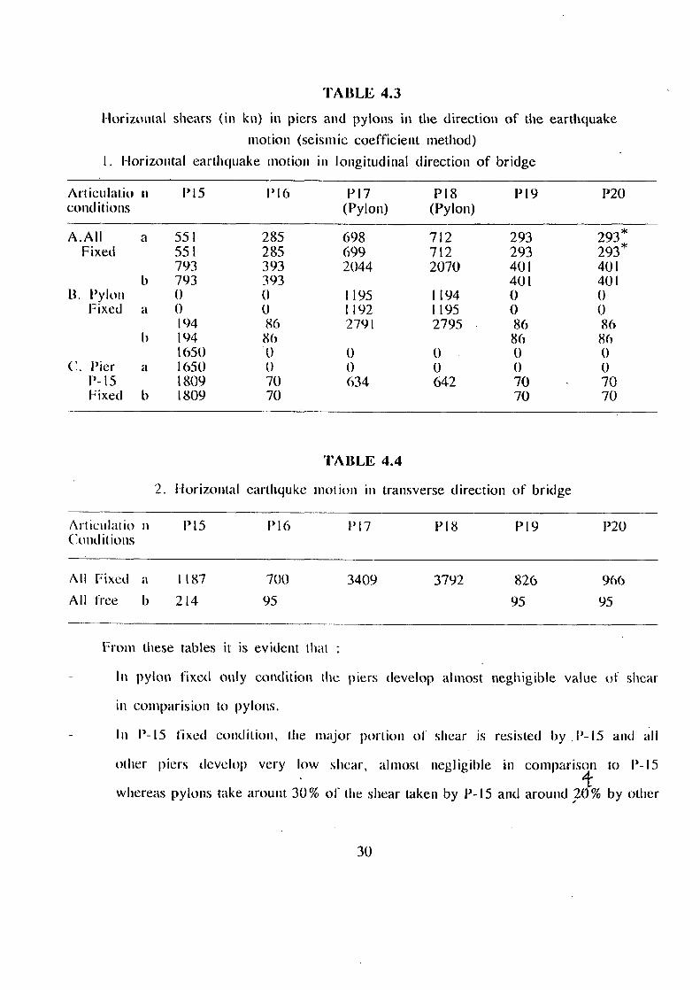
TABLE 4.3
Horiamtal shears (in kn) in piers and pylons in the direction of the earthquake motion (seismic coefficient method)
I. Horizontal earthquake motion in longitudinal direction of bridge
Artieulatio n conditions
I'15 P16 1317 (Pylon)
P18 (Pylon)
P19 I'20
A.AIl a 551 285 698 712 293 293* Fixed 551 285 699 712 293 293*
793 393 2044 2070 40 I 401 793 393 401 401
B. Pylon 0 0 1195 1194 0 0 Fixed a 0 0 1192 1195 0 0
94 86 2791 2795 86 86 b 94 86 86 86
650 0 0 0 0 0 C. l'ier a 650 0 0 0 0 0
P-15 809 70 634 642 70 70 Fixed b 809 70 70 70
TABLE 4.4
2. Horizontal earthquke motion in transverse direction of bridge
Art ieulatio n P15 P16 P17 P18 P19 P20 Conditions
All Fixed a 1187 700 3409 3792 826 966 All free b 214 95 95 95
From these tables it is evident that
In pylon fixed only condition the piers develop almost neghigible value of shear
in comparision to pylons.
In P-15 fixed condition, the major portion of shear is resisted by .P-15 and all
other piers develop very low shear, almost negligible in comparison to P-15
whereas pylons take arount 30% of the shear taken by P-15 and around ?0% by other
30

piers.
For transverse direction, the piers P-15, P- I6, P-I9 & P-20 have 33%, 20%, 25% and
30% of the shear taken by each pylon, respectively.
If the bridge is located in zone Ill, the seismic coefficient and therefore the
seismic forces get doubled.
4.9 ANALYSIS OF CABLE FORCES DUE TO SEISMIC LOAD :
The axial forces in the cables have been obtained for the four different
articulation systems considered at the supports. The forces in some typical cables,
which have been chosen as the representative ones, are given in Table 4.5.
Table 4.5
Forces in some typical cables (Inc to Seismic Load
Cable No.
Axial forces (kNS) • FOR Articulation condition A B C D
184 25 57 77 65 190 24 30 29 28 196 7 6 6 3 197 6 3 3 3 203 28 43 42 43 209 21 40 54 45 257 22 40 55 45 263 29 43 42 44 269 6 4 3 4 270 6 4 4 5 276 25 30 29 29 282 22 57 76 65
Cases A, B, C and D are same as explained in article 4.6.
31

Table 4.6.
Forces in Cable doe to dead and live loads
Cable No. DI. (t) L.L. (t) Total force (t)
85 454.1 207.3 661.4 86 423.2 280.9 704.1 87 392.6 124.9 517.5 88 362.9 91 453.9 89 334.3 62.2 396.5 90 306.8 77.3 384.1 91 280.4 79.4 359.8 92 256.2 74.1 330.3 93 234.5 55.1 289.9 94 216.2 47.4 263.6 95 202.1 29.4 231.5 96 193.I 15.3 208.4 97 203.5 15.9 219.4 98 214.1 31.3 245.4 99 230.3 47.8 278.1
200 251.4 50.1 301.5 201 276.2 60.2 336.4 202 303.8 60.4 364.2 203 333.3 82.0 415.3 204 364.6 84.0 448.6 205 397.1 84.3 481.4 206 430.1 100 530.1 207 464.4 91.2 555.6 208 499.0 78.5 577.5
From the Table 4.5 it is evident that the axial forces in the cables near the
pylons are very small compared to those away from the pylons. The 14ces in the cables
due to dead loadS and live loads are also calculated and arc given in Table 4.6. It can
he seen from Table 4.5 that higher forces are developed in case of fixity at pier V-15
(case C) in the cables farthest from the pylons. The axial forces developed in the
cables due to seismic forces are much smaller than the axial forces due to dead and live
loads. Hence it is only dead loads and live loads which govern the design of cables and
not the seismic forces.
32

U
0) E
ftf U
0)
II--- -- 1-... 1--.. ktr-l_tr:I.,_, -1- -t In cr) 1-- kr.1 a' (+1 c-,1■CD 2:-_,___Lc-t_______I
--4 M O t-- II--__In
In CD
rn CN --. ei .--. .--.
r I c--1 ri
00 (--.1 ,--- 1 lin
rfl ,--, oo
r I C) oo oo
e-t oo CD 'D c--1 c-i_____ r I i--
-t a' V) a)
-1- 00 —. —
fri CA •--,
C) CD CD 00
(--1 tn ct. ---.
Cl. cf; --,_=!
00 00 r- oo 1- -- in ---. Ch In CD ■0 •--. 00
Ch 00 0, 1'7::
— 00 v.D -1
.-- 1--- c•-■ r I --, •--. in t•-■ -- In
In --1- --ia■ L'1 --4
___rn_r.:1-______roin_ vD C) CD C,
CD CD 'n 'n ____CA.171_ x100 cri (r) ffi_in_
tri In CD CD t11rr1
tn r--I I sx:)_
-- r- in r I --. ---4___ N to f,-) C) •-■ ,-,
CD I-- t- I I---- M N-1-
I-- C) a' (41 C.Il 'Mt
rn oo vzo
--, rn In ri
I-- --I cr) el --. •"."'•4
--, CD I-- cs1 --..______
VD N N vp
vD =__.... ____Coo •7t r•-) CT --. .--+ CA 00 I----
•.--. CD t---- ,--, I-- ■CD r-i tn_e-t a' --, If) 00 •-■ CD ._._1n
- tr ,""4 N
0c0 N ," •-'1
r.-ftl. rl • • - ' . 00
c a •-• ""-.--.1"2A
c T ,-.
-0I C CI% t-i •-• .1D----1-C11._
33

4.10 DECK FORCES :
The deck forces are calculated by STAAD 3 for the seismic force. The various forces
are compared for the four articulations at the supports as given in the Table 4.7 as
shown on previous page.
From the table 4.7, it is evident that :
Very high axial forces are developed in case of fixity at pier P-15 only (Case
C), nearly 25 times of that in case of fixity at all piers (Case D). Near the
pylon P-17 this difference reduces slightly. In case of the fixity at all piers
the axial forces developed are minimum.
Higher moments about Y-axis are developed in case of fixity at pylons only.
In all the four conditions the moment about the z-axis is nearly equal except in
the case of member 2, which develops relatively lower value in case of fixicity
at pylons only (Case B).
34

CHAPTER - 5
CONCLUSIONS
5.1 GENERAL :
In the present work, the evaluation of proposed cable-stayed bridge at Naini,
Allahabad has been done for different articulations at the supports.
From the results obtained it can be concluded.
That pier P-I5 is developing higher forces except for the fixity at pylons only
(case B) condition. So it should be made much stronger than other piers.
The forces in the cables farther away from the pylons are more in comparison to
the forces near the pylons.
The pylons are developing higher forces in comparison to piers.
The forces in the cables due to seismic load are negligible as compared to forces
in cables due to dead and live loads.
In all the four cases, the moment about the z-ax is is nearly equal except in the
case of member no.2, which develops relatively lower values of forces in case of
fixicity at pylons only (Case 13).
The shears developed in case of fix ity at P- I 5 only (Case C) are much higher at
the top and bottom of pier P-I5 except pylons which develop around 30% of shear
taken by pier P-l5.
As the bridge site is located in zone 111, the seismic coefficient and hence
forces in cables get. doubled but still they are small as compared to forces due to dead
and live loads and hence are not the governing criteria for the design of cables.
35

5.2. SCOPE FOR FUTURE WORK :
Unfortuanately, due to large output data and a large number of alternative
articulation systems at the supports, it was quite tedious to select the best
alternative with respect to different support conditions. Also various other cable
stayed bridges, so far proposed and constructed, can he analysed on the same guidelines
which have been used in my work. The deformations pattern should also be analysed an the
effect of that and pylon inertia on the moments and forces in the deck can be analysed.
36

Z (a)
2.2 (b)
2,3 (c)
Fig. 2' Fundamental load-bearing elements
37

•
• •
(a)
(b)
(c)
(d) Ce)!
FIGURE 2.4 Transverse cable arrangement. (a) single-plane vertical, (b) single-plane verti- cal/lateral, (c) double-plane vertical, (d) clouble-plane (c) double-plane V-shaped,
38

(a) (b)
(c) td)
Fig. 2.5 Longitudinal cable arrangements (a) Radiating (b ) Hasp (t ) Fan (d ) Star
S.y% rit Stir/IP/wry
FICIME 2 .6
39

Para1101 bats rarallel wires Pat anal strands I lolical/tucked-coil strands
FIGURE 2.7 Various types of stay calks.

(al
Grind smooth
Syria about 1,
(b)
Cover plate
Cable Intel section
Saddle
castings
Stif lener plates
FIGURE 2 -.8 Typical (a) lower satitlic and (b) saddle. casting.

(a) (b) (c)
FIGUItE 2.'1 Alle■Itair lowrr types: (ri) midilied (b) dintilf111(1, (r) uirnlilirrl (1'1111110ml (or (kiln.
42

a
in
0 0
0
Cro
ss-
sec
tion
0
cv
C 0
a
C 0
a
43

1(1
.. a.
(0 0
0 0
0 0
(-1() 0
(-0 C
Whe
re A
rrow
sho
ws
the
free
dom
in
the
dire
ctio
n
x--0 0
4-0 0
44

4+
a., bA
Qo
C t)111 •
C
•
0
o a4
Whe
re A
rrow
sho
ws
the
free
dom
in
the
dire
ctio
n
<-0 0
k--0

jj I —
O N
s6t In 1/40 0 o
t.0 L tt A.. Cs.-b.f.- t:. .1 co -
c-i rn -•-•.---••,..t
'1 N im
9 6 (in 1,.42 PI
------,
Z1
a
tD
to N 10
utt
911 u, to
vo- 01+—e- —41 N
of
O r0
tn
In 4
-a •
to
0444
10
rr.
Eli
N N n/ N rn rn
ZEE ,
N
•
• O to
,,s O III •
tt,
Cl 0 (V ( sl ir, N'1 1... In
• 1—...'' ..". ...'.1 .4 10 N 10 tn >4 In
>. --.. ----- *---N. --wt. t
A 111 cn .- c., cn In GZE
0
LA C.
to 111 0
6E1 co co
N
9E1 4, CO N
tU
„ N
0E1 0, N
tO
9
R lD
_
(11
Va V1
0

IV tt: r.„1. )(1 •
NV, t tn In
SCE ri
N N
to N 1.3
S91 tc■ 0 ID vi
N
9 EEC
(91 n; U-
tD 0
CO 0
tf)
fU ea 2
Ez
co
UJ 0 0 Ct
LSI
0
hs1
N Ol
■0
U)
tr,
•— ec N
tc, 4
0
Oh
671
N 61
tr)
971
oD ID In
UJ .J CO
V
■zt, 7
to
0 0 e•-•
. to
0 "
U-
7
6E1 0
9El
46
N
IS I 0

NAIN
I-J O
I NT
NUMB
ERS
4 . 3
CAB
LE-S
TAYE
D BR
IGE
,
47

--i
48

u J
001111
St1.90 (C110 000 StUl
UlIrt a —
CO_
0U0 (14
11/0 la 000 C111
00U-SCV MK U0 01Z
U00 aft tolls
NI
0001t0 00100
000(1 9 00010
WO 0.0 011'10
t(0 0
Sr.'.
iba
WM UPI 0a'(°
•
0000(.
QUO 091 Ulla V UUCOU
0
r A
z 5 a. j
13 \ 4
. 8
U0 ke •••1
000(9 CIS 00 t11 114
000 S ouclu
000 SS. VOS'00 111“ 000 Oa' 00 SO 051 00
000 Sl• VIC SO 095 50
00000;. S111-111 0111,1 000 St1- 1111,10 0490u
0000S1- OSC IV
000SLI- 91111
000 00t- tttli 00440
000V.(- 00410 00( 011 000 051- (trill 0055
000 SI 4- 0(5 05 occ i
U1)0.00t. C0C114 004(0
000 Stt• VC( (I0 0491
OoTOSC- ClICGO 19449 !
49
H. 44-
0
N. •

23 0 5000 0. 115000
50
's,, ., r< 6
41112
. 3 \ 4 3 s 7 \ 8 10 12 13 r
LO 26 0 5000 130000
LONGITUDINAL SECTION IN MAIN SPAN (HALF SPAN) SCALE 1:500
12 b 5000-60000
or ANCIllFt PIER LONGITUDINAL SECTION IN SIDE SPAN
SCALE 1:500
. .x.
/ I
203 ,_. 1563 1500 ,7,00 1:70
1 1 o ,
vz ' 2 ..011
I 6201500
-i 1
500
2000 INTERNEENATE CROSS BEAM 0 SEGO CE3FTRES
( 618
. — 1 150 20020C .7 i--6
7500
2.5%
VARIM 1E200 AT PI 6/P19. 16600 AT P15/P20
600.600
VAMES. 26009 AT P I C/P g. 24400 AT P15/P20
1
LNORWAL CROSS BEAU PER 5m)
. 7500
250 LI 4: 15 • , '3E° 200
:18 1.4450
vAR. ,200 1500
(500 600
3;22
1500
•
200
HALF SECTION A—A • ' SCALE 1:100
HALF SECTION B—B SCALE 1:100
FIG. 4.6
CROSS BEND/ ABOVE PIERS
3200
75 ASPHALTIC CONCRETE
2.5=
OF PYLON
1

2 Li
. 2 z 0 .
- 000c
00(31 (JUl19 0001
— 0000C
• H
c e.
0 • LI Ill 6, Vt
Soc
WC 2 9 VIIJ Huruiro UY0tIy lI
(.I:
1
E .. - r __
- -
0001:
••••-•. 1..10
1.41 11 --- trt
(1 Ct . • :
I O. ;.1. • . 41: tl
— — — t 41 I , 0
.... ...r. ... o
[1:L77 212 0;:i
000 9 11)11 110030v 01,0 )
.
T E-..- .. ..... ..... • 1 • , v / • ( ),..01,---(... - - - -7 111,
t
't -1,1- -E- -IL'il- . .
r .
1 IA v. .-.1 0 1...
. (.; 01 5 1.1
1.1
I 1,—, 1/1
1 11 ________::› ___..i o ..)
Ikii CV
ri 1
r' I'll il :
Ir- el
..,.. .._ ..-
I'
".3 ..,, ru b.il 13: ri)i
c.. 1(1 q :,I '' —11 cs Duo 1------ '- LI $3 1.4 V' VI
ZZ r e 41.
•il ti ./I 1, it:, I ! 1.. ■ ;1 ::
n to us, , :. I: :: ■.i
:-... ••_. :.,. • t) • ii 0
4. 0 .., 9 •Il
tl
■ Z!
1p,'■ - a 1
•-I I' I
.
,.: it
( ,.. ....--....-1 -,-----__ ......_, z........................
, .- ,1,......-- • ;.i 1
.......... -___ . -.-,-.--........... „.._::.,.......<.....______ I , ........_._ ..._,
_ ._, .., .v.
CI g
..- ,-.." . ..".../ --..._„. ......"'. ......'s ...:;.<,,.,,,'.—
'.......-; :"' '.5>'-' ::•''---.. -...'
.-...r. ,..,'-
hoc
WOO —
00060 ( 0(91111 11011.1 H11111 )
othli CI -14111, twAyliVI
51

IG G
r
t.
•
In
5 2 11
1626
1 -----iT-
L 8 7no
'I ( I
r. z 0
t4 ('ci t inq ••• —0 in -.1
Cl)
tit
13
A -1
U
3500
. •
IcC
111
11
375G i■rj
tll
4(0
II I
II
,
/ , I I II
/
H
52

18.2
172/ 24 3
171/242
170/241
370 3.0 3.5 -r
178/249
177/248 176/247
183/254
25.0
236 182/253 T
?L 255
25.0 169/240 175/246
16t / 230 174/245
179/250 180/251
181/252
27.0 167/238 173/244
37.0
338 341
337 340
339/342
AL L ABAD/ NAINI
1 4 ' 13.0 -14
8.5
FIG 4.9 C.S. B. NAM) PYLON MEMBER NUMBERS
53

5.0
29 , 114/132
27.0
37, 0
To 3.0 35 -r
1-- 119/137 12 8/146 1181135 127/145 117/135 126/144 116/134 125 /1 43
18.2
25.0
115/133 124/142
130/148
123/141
121 139
122/140
ALL AHABA0/ NAINI
166/1686 8.5 13.0
8.5
165 167
FIG. A-'1:0 C. S. B. NA I NI PYLON JOINT NUMBERS

REFERENCES
1 Agarwal, T.P., (1979), "Analysis of Concrete Cable-Stayed Bridges", Phi) Thesis,
University of Roorkee, Roorkee (India).
2. Agarwal, T.P., Krishna, P., Arya, A.S., (Nov. 1987), " Cantilever Construction
of Cable-Stayed Bridges", Proc. International Conference on Cable-Stayed
Bridgtes, Proc. International Conference on Cable-Satyed Bridges, Bangkok, PP.
902 - 916.
3. Ahamad, Suhail, (1977), "Influence of Horizontal Subgrade Reaction on Dynamic
Behavious of Cable-Stayed Bridges", M.E. Thesis, Department of Earthquake
Engineering, University of Roorkee (India).
4. Arora, H.C., (1993), "Soil Structure interaction and Cable Tension Adjustment
studies of a predestrian Cable-Satyed Bridge", M.E. Thesis, Department of Civil
Engineering, University of Roorkee (India).
5. Chakraborty, S.S., and Sengupta, S., (1987), "Cable-Stayed Bridges- Indian
Experience", 'Proc. International Conference on Cable-Stayed Bridges, Bangkok,
PP. 125-136.
6. Gimsing , NJ., (1983), "Cable Supported Structures", John Wiley and Sons Ltd.,
Norwich.
7
Krishna, P. and Kumar, Krishen, (1987), "Cable-Stayed Bridges in India", Proc.
International Conference on Cable-Stayed Bridges, Bangkok, PP. 111-124.
8. Lee, David., (1987), "The Place of Innovation in Cable-Stayed Bridges ", Proc.
International Conference on Cable-Stayed Bridges , Bangkok, PP. 34-42.
9. Martin, H.C., (1966), "Introduction to Matrix Methods of Structure Analysis",
McGraw-H ill Book Company, New-York.
Podolny, W. and Scalzi, J., (1986), "Construction and Design of Cable-Stayed
55

Bridges ", John Wiley and Sons, USA.
11. Podo W.J., (1971), "Static Modulus of Elasticity of Concrete as Affected by
Density", ACI Journal Vol. 57, No. - 6, PP. 679-687.
12. Razdan, K.K., (1993), "Parametric Study of a Pedestrian Cable-Stayed Bridge",
M.E. Thesis, Department of Civil Engineering, University of Roorkee (India).
13. Stipanic, Bratislay., (1987), "Some Specific analysis Problems Related to Design
of Cable-Stayed Bridges", Proc. International Conference on Cable-Stayed
bridges, Bangkok, PP. 150-163.
14. Troitsky, M.S., (1988), "Cable Stayed Bridges ", BSP Professional Books.
15. The American Society of Civil Engineer, (May 1977), "Tentative Recommendation
for Cable-Stayed Bridge Structures", ASCE J. Struct. Divn. Proc, 103, No. ST5,
PP. 929-939.
16. Taylor, Peter, R., (1987), "Recent Developments in the Technology of Cable-
Stayed Bridges", Proc. International Conference on Cable Stayed Bridges,
Bangkok, PP. 51-62.
17. Walther, R. et. al., (1988), "Cable-Stayed Bridges ", Thomas Telford, London.
18. Priestlely, M.J.N., Seible, F., Calvi, G.M., Seismic Design and Retrofit of
. Bridges , John Wiley and Sons.
19. 11ffi World Conference on Earthquake Engineering, Acapulco, Mexico, June /3-18,
1996..
20. Earthquake Engineering, Tenth World Conference, 1992 Balkema, Rotterdam.
56

APPENDIX — A
Name and country Oper- ational date Type of cable Deck --depth material
Pylons material System On) Longitudinal Transverse
1
-- 2 --..
Tempul Aqueduct, Spain 1925 Twisted 2.10 in Concrete Concrete _1‘1 - .: • - A/ III
- s -. :r. .- 11 1;11,111 I I 71) II) .1. .1 llochenatter Bridge, 1956 Locked-coil 1.50 in
Composite Steel
_Li_nu; . Is ./ . r,...... ,.., --- ■ 1
I. .4
.• .1 ...It Ulf i 1.1111 j 3 l'HG Exhibition llall, Brussels, Belgium) 1958 Locked-coil 1.30 to Steel Steel ....in
inn 1
1 !oo i 8.2.1
4 Schillastrasse footbridge, FRG 1961 Parallel wires 0.50 as Steel Steel l:
eiliiii ,74.1 V.1.1 1 14 2.2
S
-- liilicherstrasse Bridge, FRG 1963 Locked-coil I-25- 1:65 in
Stccl
Steel --..-- I r
..."--.. 71*-0 ,. "I'-----...,N.1
. ._ . _..., 1 '41 al I WOO 1 • 74--
8.3.1 L Al 1111
6
7 ..---1
Dnieper Bridge, Kiev, USSR 190 Locked-coil 1-1B1 in Concrete Conctete r
- , ,,,, %!111 j
1.] I, 11'., 9n I 14401 .I.
Centre Canal, Obourg, Belgium 1966 Twisted 0.60 as Concrete •
Concrete .
-- '' 7 r I '',....- -. -. 20o1 K2.)
I 11/ 01 J.
, 11/.1 J 8 Tiber Bridge, fdagliana, Italy
1967 Parallel wires 343 4:0 in Ccatcrett
Concrete 1 .1.1 no
I _ a 11h, I, Lts..oxt .i. s. ■ !•%1 ,
9
10
Neckar Railway Bridge, FRG 1968 Strengthened It SJ 2.5 3.2 in Concrete / steel 0.90 in Concrete
01111:1 etc 1 no., I r 11 SA.1
L '100 A t; so j
Pretoria Aqueduct, South Aft ica 1968 Parallel wires Concrete 1;!,0 A 8.5.1 L' MIMI :11.n1 i
II Harmsen Bridge, liollancl 1968 Locked-coil 1401 in Steel Steel 1 ''''''—'-*-- kl, "4'4' 1 r I ill s. itrl gr.'L in11.40 1470 .1
12 Pontde la Bourse, Le flavre, France 1969 Twisted 1.07 to Steel Steel k ii.—t— s: -:-----?- • 7 1 .1 1111
71104 j 142.4
13 Aqueduct and footbridge over the Riser Barwon, Australia 1969 Strands 1 0 2,3 in Concrete Concrete -r„._ ,. ,,„ _. , __ T. 1 8.5.2
I !wl MI 1 Os MI .L, !.... 1 14 Footbridge over she nundesallte, FRG 1971 Locked-coil 0.65 m Steel Steel I
.--- i\ X.2.5
man ,. tool. tool t 5 Footbridge at Villingen, FRG 1972 Parallel wires 060 to Concrete Steel 'itIIM; I 8.2,6
cioal _!650., ..t TABLE -1(a)
57

]976 I\
System (m)
Longitudinal Transverse §
641.1." 6750 -6 r _ um tor
o'irn 11.2.7
35 SO _36 7.0
L 4701 1 61 so 1.21300_
cgs() 140 00 69
la '7o er:' ;---..,........ 1
15101 SO 00
I
8.2.8
8.2.9
• 16141 n. 41600 •
19160 8.3.2
1. 4110 176 30 4117
1145 1
1 6671r 110141 65.10
7" ,-".I N
i L 13? Pr 46 CS
\\ 3c1
1rn
R.7.3
8.2.11)
1_6660_ 4 17950
8.5.4 71 00
eo ns
!41
arm i .13100 13400.
36144 1111
.
_01.,0_...L4065 ,1
A APPENDIX
Name and °per- Type of cable
beck Pylons —material country rational
date —depth
—material
16 !)ridge over the htnine, llochst, FRG
1972 Parallel bars 2.70 m Concrete
Concrete
17 Footbridge over Mount Street, Australia
1972 Locked-coil 0.60 no Concrete
18 Canal bridge over the Nero, Italy
1977 Parallel wires 1.74 to Steel
Concrete
19 'fridge hoer the Rio Magdalena, Colombia
1974 Prestressed concrete
2.80 m Concrete
'encrere
20 Footbridge at Diekirch, Lusenobourg
1974 Parallel wires 0.60 m Concrete
21 Stadium footbridge at Wilmerstlorf, FRG
1914 Locked-coil 1 .00 to Steel
Steel
22 Frankliotrasse Midge, 1. R(1
1974 1.ocked-coil (I 8 -17 1 Steel
Steel
CWIC1 elf
Sled
Steel
17 Midge over Ore Danube Canal, Austria
1975 Locked-coil 2.80 no Concrete
24
25
Silks Harbor Ilridge, (ISA
1973 twisted 2110 no Ccullrlos ire
11 ..r.r.ge over the Meuse, Ileer-
lllll nt„ hdgiunt
1915 Locked-coil 1 .90 or Composite
6 Footbridge over the Neckar at hlannlitim, FRG
1915 Parallel wires 0.60 to (-macre
Concre t e
27
28
Aqueduct and footbridge over the Reuss, Swiiretland
1975 Parallel wires Steel Steel
.4Incr ere K wang- hr. taiwan
1977 tirrands I.K0 in Concrete
29 Matorgayama, Japan
1918 Parallel bars 1.80 Concrete
Concrete
30 K awasakillashi footbridge, Japan
1918 1.ocked-coil 134m Steel
Steel
TABLE — .1( b)
5$3

Pylons - material
Concrete
Conerele
.01111eif
723x1 I --
- • .
•10 1 1.-1 110 j
Concrete
70411 ; r \::."--- ...
---.2.1-4-.- ---\--'"---'---.-----1 1 -11-17- 01.01/
(700 ,
1.
•
71110 76 (11
I 0
APPENDIX - A
Name and country
Oper-ational date
1979
1980
1980
type of 1)eck cable —depth
— martini,
System lint
Longitudinal Transverse 31 Railway bridge
over the 13125 motorway, England
Parallel wires 2.80 in Concrele
8.4.2
11
32 Bridge over the Danube at Mellen, ERG
Prestressed 4-20 in
concrete Concrete
Locked-coil 2-10 m Concrete
8.3.4 AA NI
61'.1111
33 Rio Ebro (bridge, Spain
34 Pipe-bridges over the Sete, Italy
1980 Locked-coil 0 1 -60 nu Steel pipe
8.5.5
Meylnn footbridge, France
1980 35 Strands 1.50 in Concrete
Coricr etc 8.2.12
I1001 1 100or
111hor footbridge, France
Prestressing f 1511 m cables. I Concrete stranded
19811 tuncrele 8.2.13
37 Footbridge over the Neckar near Ludwigshurg. FRG
1980 Locked-coil 0.75 m Steel
Sleet 8.2.14
38 Ube footbridge, /apart
Parallel wires 0.50 m Concrete
1980 Concrete
Concrete
Steel
Steel
Concrete
Concrete
Concrete
Concrete
1100 is,
• 17 110 111111 1)110 •
39 Katsomoto 'Bridge, Japan
1981 'wisted 070 m Concrete
40 Ileinrich Ehrhardt Bridge, FRG
3981 Locked-coil 1.77 m
Steel v.:7P
.1?°e°1 00 00 I 30100. j
Bridge over the River Tartans, Italy
41 1983 Locked-coil 2.30 in Steel ..11 tat . 8.3.5
5 -101 L- A0 00 1 I/ JO
Diepoldstor Bridge, Switzerland
42 1985 l'arallel wires 0-55 nt Concrete • Oro
AO y 97 00
Napoleon Bridge, Switzerland
1980 Parallel wires It-) 1 3 in Concrete
mien —7,7!
non liz.17.1
▪
9920 A 9970 1^1« 7.60
8.3.6
Bridge over the Moine at Levey, Switzerland
1982 Parallel wires I 0 39 in 1 ....
—or*.
8.3.7 Concrete
Bridge over the /thane at St• Maurice, Switzerland
Parallel wires I I. 10 1%1 1987 8.3.13 Composite
TABLE — (C)