alteon os 20.0 command reference-layer 2-7 gbe switch...
TRANSCRIPT

���������������
��������� ��
Part Number: 25K9199, October 2004
TM
Layer 2-7 GbE Switch Modulefor IBM BladeCenter
4655 Great America ParkwaySanta Clara, CA 95054
www.nortelnetworks.comReference: 215655-C

Alteon OS 20.2 Command Reference
225K9199, October 2004
Copyright © 2004 Nortel Networks, Inc., 4655 Great America Parkway, Santa Clara, California, 95054, USA. All rights reserved. Part Number: 25K9199.
This document is protected by copyright and distributed under licenses restricting its use, copying, distribution, and decompilation. No part of this document may be reproduced in any form by any means without prior written authorization of Nortel Networks, Inc. Documentation is provided “as is” without warranty of any kind, either express or implied, including any kind of implied or express warranty of non-infringement or the implied warranties of merchantability or fitness for a particular purpose.
U.S. Government End Users: This document is provided with a “commercial item” as defined by FAR 2.101 (Oct. 1995) and contains “commercial technical data” and “commercial software documentation” as those terms are used in FAR 12.211-12.212 (Oct. 1995). Government End Users are authorized to use this documentation only in accordance with those rights and restrictions set forth herein, consistent with FAR 12.211- 12.212 (Oct. 1995), DFARS 227.7202 (JUN 1995) and DFARS 252.227-7015 (Nov. 1995).
Nortel Networks, Inc. reserves the right to change any products described herein at any time, and without notice. Nortel Networks, Inc. assumes no responsibility or liability arising from the use of products described herein, except as expressly agreed to in writing by Nortel Networks, Inc. The use and purchase of this product does not convey a license under any patent rights, trademark rights, or any other intellectual property rights of Nortel Networks, Inc.
Originated in the USA.
Alteon OS, and Alteon are trademarks of Nortel Networks, Inc. in the United States and certain other countries. Cisco® and EtherChannel® are registered trademarks of Cisco Systems, Inc. in the United States and certain other countries. Any other trademarks appearing in this manual are owned by their respective companies.
25K9199, October 20043
Contents
Preface 13Who Should Use This Book 13How This Book Is Organized 13Typographic Conventions 15How to Get Help 16
Chapter 1: The Command Line Interface 17Connecting to the Switch 18
Management Module Setup 18Factory-Default vs. MM assigned IP Addresses 18Default Gateway 19Configuring the Management Module for Switch Access 19
Connecting to the Switch via Telnet 21Running Telnet 21Using a BOOTP Server 22
Establishing an SSH Connection 22Running SSH 23
Accessing the Switch 24Setup Versus CLI 26Command Line History and Editing 26Idle Timeout 26
Chapter 2: First-Time Configuration 27Using the Setup Utility 27
Information Needed For Setup 27Starting Setup When You Log In 28Stopping and Restarting Setup Manually 29
Stopping Setup 29Restarting Setup 29
Setup Part 1: Basic System Configuration 29

Alteon OS 20.2 Command Reference
4 � Contents25K9199, October 2004
Setup Part 2: Port Configuration 31Setup Part 3: VLANs 33Setup Part 4: IP Configuration 34
IP Interfaces 34Default Gateways 35IP Routing 36
Setup Part 5: Final Steps 37Optional Setup for SNMP Support 38Optional Setup for Telnet Support 38
Setting Passwords 39Changing the Default Administrator Password 39Changing the Default User Password 41Changing the Default Layer 4 Administrator Password 42
Chapter 3: Menu Basics 45The Main Menu 45Menu Summary 46Global Commands 47Command Line History and Editing 49Command Line Interface Shortcuts 50
Command Stacking 50Command Abbreviation 50Tab Completion 50
Chapter 4: The Information Menu 51Information Menu 51System Information 53General System Information 54Show Last 30 Syslog Messages 55FDB Information Menu 57
Show All FDB Information 59Clearing Entries from the Forwarding Database 59
Link Aggregation Control Protocol menu 60Link Aggregation Control Protocol 60Spanning Tree Information 62Trunk Group Information 64VLAN Information 65IP Routing Information 68

Alteon OS 20.2 Command Reference
Contents � 525K9199, October 2004
Show All IP Route Information 69ARP Information 70
Show All ARP Entry Information 71ARP Address List Information 72
BGP Information Menu 73BGP Peer information 73BGP Summary information 74Dump BGP Information 74
OSPF Information 75OSPF General Information 76OSPF Interface Information 77OSPF Database Information 78OSPF Information Route Codes 79
IGMP Multicast Group Information 80IGMP Multicast Router Port Information 80IGMP Multicast Router Port Information 81IP Information 82VRRP Information 82SLB Information 84
Session Table Information 85Samples of Session Dumps for Different Applications 87
Session dump information in Alteon OS 88Show All Layer 4 Information 90
Link Status Information 91Port Information 92Information Dump 93
Chapter 5: The Statistics Menu 95Statistics Menu 95Port Statistics Menu 97
Bridging Statistics 98Ethernet Statistics 99Interface Statistics 102Interface Protocol Statistics 104Link Statistics 105RMON Statistics 105
FDB Statistics 109LACP Statistics 110

Alteon OS 20.2 Command Reference
6 � Contents25K9199, October 2004
OSPF Statistics Menu 112OSPF Global Statistics 113
IP Statistics 117Route Statistics 119ARP statistics 120VRRP Statistics 121DNS Statistics 122ICMP Statistics 122IGMP Statistics 124Interface Statistics 125TCP Statistics 127UDP Statistics 129Load Balancing Statistics Menu 130
Server Load Balancing SP statistics Menu 132SP Real Server Statistics 133
Real Server SLB Statistics 135Per Service Octet Counters 135
Real Server Group Statistics 136Virtual Server SLB Statistics 137Filter SLB Statistics 137SLB Layer7 Statistics Menu 138
Layer7 Redirection Statistics 138Layer 7 SLB String Statistics 139Layer 7 SLB Maintenance Statistics 140
SLB Secure Socket Layer Statistics 142File Transfer Protocol SLB and Filter Statistics Menu 143
Active FTP SLB Parsing and Filter Statistics 143Passive FTP SLB Parsing Statistics 144FTP SLB Maintenance Statistics 144FTP SLB Statistics Dump 145
RTSP SLB Statistics 146DNS SLB Statistics 146WAP SLB Statistics 148SLB TCP Rate Limiting Statistics 150SLB Maintenance Statistics 150Clearing the SLB Statistics 152
Management Processor Statistics 153MP Packet Statistics 154
Alteon OS 20.2 Command Reference
Contents � 725K9199, October 2004
TCP Statistics 155UCB Statistics 155MP-Specific SFD Statistics 156CPU Statistics 156SP Specific Statistics Menu 156
SNMP Statistics 158NTP Statistics 161Statistics Dump 162
Chapter 6: The Configuration Menu 163Configuration Menu 163Viewing, Applying, and Saving Changes 164
Viewing Pending Changes 165Applying Pending Changes 165Saving the Configuration 165
System Configuration 167System Host Log Configuration 169SSH Server Configuration Menu 170RADIUS Server Configuration 171TACACS+ Server Configuration Menu 172NTP Server Configuration 174System SNMP Menu 176System Access Menu 178User Access Control Configuration 179
Port Configuration 181Port Link Configuration 183Temporarily Disabling a Port 184
Port Mirroring Menu 184Port-Mirroring Menu 185
Layer 2 Menu 186Spanning Tree Configuration 188Bridge Spanning Tree Configuration 189Spanning Tree Port Configuration 191Trunk Configuration 192IP Trunk Hash menu 193
Layer 2 IP Trunk Hash menu 193Layer 3 IP Trunk Hash menu 194
Link Aggregation Control Protocol menu 196
Alteon OS 20.2 Command Reference
8 � Contents25K9199, October 2004
LACP Port menu 196VLAN Configuration 198
Layer 3 Menu 200IP Interface Configuration 202Default Gateway Configuration 203
Default Gateway Metrics 204IP Static Route Configuration 205IP Forwarding Configuration 206
Local Network Route Caching Definition 206Defining IP Address Ranges for the Local Route Cache 207Network Filter Configuration 208Routing Map Configuration 209
IP Access List Configuration Menu 211Autonomous System Filter Path 212
Routing Information Protocol Configuration 213Open Shortest Path First Configuration 215
Area Index Configuration Menu 216OSPF Summary Range Configuration Menu 218OSPF Interface Configuration Menu 219OSPF Virtual Link Configuration Menu 220OSPF Host Entry Configuration Menu 222OSPF Route Redistribution Configuration Menu. 223OSPF MD5 Key Configuration Menu 224
Border Gateway Protocol Configuration 224BGP Peer Configuration Menu 226BGP Redistribution Configuration Menu 228BGP Aggregation Configuration 229
IGMP Configuration 230IGMP Snooping Configuration 231IGMP Static Multicast Router Configuration 232IP Port Configuration 233Domain Name System Configuration 234Bootstrap Protocol Relay Configuration 235
VRRP Configuration 236Virtual Router Configuration 237
Virtual Router Priority Tracking Configuration 240Virtual Router Group Configuration 242
Virtual Router Group Priority Tracking Configuration 244

Alteon OS 20.2 Command Reference
Contents � 925K9199, October 2004
VRRP Interface Configuration 246VRRP Tracking Configuration 247Default Gateway Metrics 248
Setup 249Dump 249Saving the Active Switch Configuration 250Restoring the Active Switch Configuration 250
Chapter 7: The SLB Configuration Menu 251SLB Configuration 251
Filtering and Layer 4 (Server Load Balancing) 254Real Server SLB Configuration 254
Real Server Layer 7 Configuration 258Real Server Group SLB Configuration 259
Server Load Balancing Metrics 262Virtual Server SLB Configuration 264
Virtual Server Service Configuration 266Virtual Server RTSP Configuration 270Cookie-Based Persistence 271
SLB Filter Configuration 272Defining IP Address Ranges for Filters 276Advanced Filter Configuration 277
Advanced Filter TCP Configuration 279IP Advanced Menu 280Layer 7 Advanced Menu 281ICMP Message Types 282
Port SLB Configuration 283Layer 7 SLB Resource Definition Menu 285
Web Cache Redirection Configuration 286Server Load Balance Resource Configuration Menu 287
WAP Configuration 288Synchronize Peer Switch Configuration 289
Peer Switch Configuration 290Advanced Layer 4 Configuration 291
SYN Attack Detection Configuration 293Scriptable Health Checks Configuration 295WAP Health Check Configuration 296Proxy IP Address Configuration Menu 297
Alteon OS 20.2 Command Reference
10 � Contents25K9199, October 2004
SLB Peer Proxy IP Address Configuration Menu 298
Chapter 8: The Operations Menu 299Operations Menu 299Operations-Level Port Options 301Operations-Level SLB Options 302Operations-Level VRRP Options. 303Operations-Level IP Options 303
Operations-Level BGP Options 304
Chapter 9: The Boot Options Menu 305Boot Menu 305Updating the Switch Software Image 306
Downloading New Software to Your Switch 306Selecting a Software Image to Run 307Uploading a Software Image from Your Switch 308
Selecting a Configuration Block 309Resetting the Switch 310
Chapter 10: The Maintenance Menu 311Maintenance Menu 311System Maintenance Options 313Forwarding Database Options 313Debugging Options 315ARP Cache Options 316IP Route Manipulation 317IGMP Configuration 319IGMP Multicast Router Port Information 320IGMP Multicast Router Port Information 321Uuencode Flash Dump 321TFTP System Dump Put 322Clearing Dump Information 322Panic Command 323Unscheduled System Dumps 323

Alteon OS 20.2 Command Reference
Contents � 1125K9199, October 2004
Appendix A: Alteon OS Syslog Messages 325LOG_WARNING 325LOG_ALERT 326LOG_CRIT 326LOG_ERR 327LOG_NOTICE 333LOG_INFO 335
Appendix B: Alteon OS SNMP Agent 337Working with Switch Images and Configuration Files 340
Loading a new switch image 341Loading a saved switch configuration 341Saving the switch configuration 342Saving a switch dump 342Saving a switch image 343
Glossary 345
Index 349

Alteon OS 20.2 Command Reference
12 � Contents25K9199, October 2004

25K9199, October 200413
Preface
The Alteon OS 20.2 Command Reference describes how to configure and use the Alteon OS software with your GbE Switch Module.
For documentation on installing the switches physically, see the Installation Guide for your GbE Switch Module.
Who Should Use This Book
This Command Reference is intended for network installers and system administrators engaged in configuring and maintaining a network. The administrator should be familiar with Ethernet concepts, IP addressing, the IEEE 802.1d Spanning Tree Protocol, and SNMP configuration parameters.
How This Book Is Organized
Chapter 1 “The Command Line Interface,” describes how to connect to the switch and access the information and configuration menus.
Chapter 2 “First-Time Configuration,” describes how to use the Setup utility for initial switch configuration and how to change the system passwords.
Chapter 3 “Menu Basics,” provides an overview of the menu system, including a menu map, global commands, and menu shortcuts.
Chapter 4 “The Information Menu,” shows how to view switch configuration parameters.
Chapter 5 “The Statistics Menu,” shows how to view switch performance statistics.
Chapter 6 “The Configuration Menu,” shows how to configure switch system parameters, ports, VLANs, Spanning Tree Protocol, SNMP, Port Mirroring, IP Routing, Port Trunking, and more.

Alteon OS 20.2 Command Reference
14 � Preface25K9199, October 2004
Chapter 7 “The SLB Configuration Menu,” shows how to configure Server Load Balancing, Filtering, Global Server Load Balancing, and more.
Chapter 8 “The Operations Menu,” shows how to use commands which affect switch per-formance immediately, but do not alter permanent switch configurations (such as temporarily disabling ports). The menu describes how to activate or deactivate optional software features.
Chapter 9 “The Boot Options Menu,” describes the use of the primary and alternate switch images, how to load a new software image, and how to reset the software to factory defaults.
Chapter 10 “The Maintenance Menu,” shows how to generate and access a dump of critical switch state information, how to clear it, and how to clear part or all of the forwarding database.
Appendix A, “Alteon OS Syslog Messages,” shows a listing of syslog messages.
Appendix B, “Alteon OS SNMP Agent,” lists the Management Interface Bases (MIBs) sup-ported in the switch software.
“Glossary” includes definitions of terminology used throughout the book.
“Index” includes pointers to the description of the key words used throughout the book.
Alteon OS 20.2 Command Reference
Preface � 1525K9199, October 2004
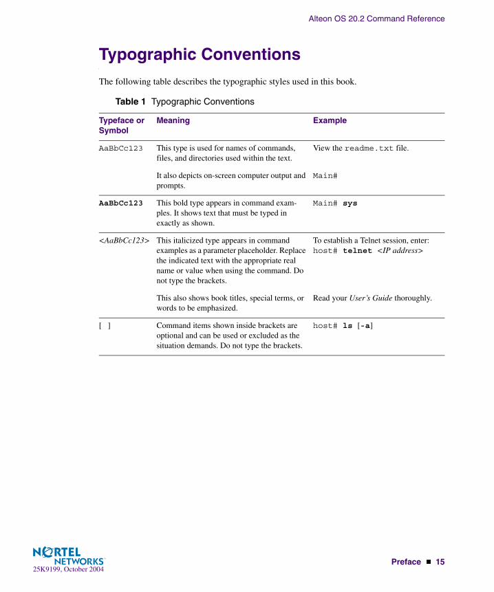
Typographic Conventions
The following table describes the typographic styles used in this book.
Table 1 Typographic Conventions
Typeface or Symbol
Meaning Example
AaBbCc123 This type is used for names of commands, files, and directories used within the text.
View the readme.txt file.
It also depicts on-screen computer output and prompts.
Main#
AaBbCc123 This bold type appears in command exam-ples. It shows text that must be typed in exactly as shown.
Main# sys
<AaBbCc123> This italicized type appears in command examples as a parameter placeholder. Replace the indicated text with the appropriate real name or value when using the command. Do not type the brackets.
To establish a Telnet session, enter:host# telnet <IP address>
This also shows book titles, special terms, or words to be emphasized.
Read your User’s Guide thoroughly.
[ ] Command items shown inside brackets are optional and can be used or excluded as the situation demands. Do not type the brackets.
host# ls [-a]

Alteon OS 20.2 Command Reference
16 � Preface25K9199, October 2004
How to Get Help
If you need help, service, or technical assistance, see the “Getting help and technical assis-tance” appendix in the Nortel Networks Layer 2-7 GbE Switch Module for IBM eServer Blade-Center Installation Guide on the IBM BladeCenter Documentation CD.
25K9199, October 200417
CHAPTER 1The Command Line Interface
Your GbE Switch Module is ready to perform basic switching functions right out of the box. Some of the more advanced features, however, require some administrative configuration before they can be used effectively.
The extensive Alteon OS switching software included in your switch provides a variety of options for accessing and configuring the switch:
� A built-in, text-based command line interface and menu system for access via a Telnet ses-sion
� SNMP support for access through network management software such as IBM Director or HP OpenView
� Alteon OS Browser-Based Interface (BBI)
The command line interface is the most direct method for collecting switch information and performing switch configuration. Using a basic terminal, you are presented with a hierarchy of menus that enable you to view information and statistics about the switch, and to perform any necessary configuration.
This chapter explains how to access the Command Line Interface (CLI) for the switch.
Alteon OS 20.2 Command Reference
18 � Chapter 1: The Command Line Interface25K9199, October 2004
Connecting to the Switch
You can access the command line interface in any one of the following ways:
� Using a Telnet via the management module
� Using a Telnet connection over the network
� Using a SSH connection to securely log into another computer over a network
Management Module SetupThe BladeCenter GbE Switch Module is an integral subsystem within the overall BladeCenter system. The BladeCenter chassis includes a management module (MM) as the central element for overall chassis management and control.
You can use the 100-Mbps Ethernet port on the Management Module to configure and manage the GbE Switch Module. The GbE Switch Module communicates with the management mod-ule through port MGT1 and port MGT2, which you can access through the 100 Mbps Ethernet port on the management module. The factory default settings will only permit management and control access to the switch module through the 10/100 Mbps Ethernet port on the manage-ment module. You can use the four external 10/100/1000 Mbps Ethernet ports on the switch module for management and control of the switch by selecting this mode as an option through the management module configuration utility program (see the applicable BladeCenter Instal-lation and User’s Guide publications on the IBM BladeCenter Documentation CD for more information).
Factory-Default vs. MM assigned IP Addresses
Each GbE Switch Module must be assigned its own Internet Protocol address, which is used for communication with an SNMP network manager or other transmission control protocol/Internet Protocol (TCP/IP) applications (for example, BootP or TFTP). The factory-default IP address is 10.90.90.9x, where x corresponds to the number of the bay into which the GbE Switch Module is installed. For additional information, see the Installation Guide). The man-agement module assigns an IP address of 192.168.70.1xx, where xx corresponds to the number of the bay into which each GbE Switch Module is installed, as shown in Table 1-1:

Alteon OS 20.2 Command Reference
Chapter 1: The Command Line Interface � 1925K9199, October 2004
Default Gateway
The default Gateway IP address determines where packets with a destination address outside the current subnet should be sent. Usually, the default Gateway is a router or host acting as an IP gateway to handle connections to other subnets of other TCP/IP networks. If you want to access the GbE Switch Module from outside your local network, use the management module to assign a default Gateway address to the GbE Switch Module. Choose I/O Module Tasks > Management from the navigation pane on the left, and enter the default Gateway IP address (for example, 192.168.70.125). Click Save.
Configuring the Management Module for Switch Access
Complete the following initial configuration steps:
1. Connect the Ethernet port of the management module to a 10/100 Mbps network (with access to a management station) or directly to a management station.
2. Access and log on to the management module, as described in the BladeCenter Manage-ment Module User’s Guide on the IBM BladeCenter Documentation CD. The management module provides the appropriate IP addresses for network access (see the applicable Bla-deCenter Installation and User’s Guide publications on the IBM BladeCenter Documenta-tion CD for more information).
Table 1-1 GbE Switch Module IP addresses, based on switch-module bay numbers
Bay number Factory-default IP address IP address assigned by MM
Bay 1 10.90.90.91 192.168.70.127
Bay 2 10.90.90.92 192.168.70.128
Bay 3 10.90.90.94 192.168.70.129
Bay 4 10.90.90.97 192.168.70.130

Alteon OS 20.2 Command Reference
20 � Chapter 1: The Command Line Interface25K9199, October 2004
3. Select Management on the I/O Module Tasks menu on the left side of the BladeCenter Management Module window. See Figure 1.
Figure 1 Switch management on the BladeCenter management module
4. You can use the default IP addresses provided by the management module, or you can assign a new IP address to the switch module through the management module. You can assign this IP address through one of the following methods:
� Manually through the BladeCenter management module.
� Automatically through the IBM Director Configuration Wizard (when it becomes available)
NOTE – If you change the IP address of the GbE Switch Module, make sure that the switch module and the management module both reside on the same subnet. Both management module ports (Ethernet 0 and Ethernet 1) must reside on the same subnet.
Alteon OS 20.2 Command Reference
Chapter 1: The Command Line Interface � 2125K9199, October 2004
5. Enable the following features in the management module (Switch Tasks > Management > Advanced Management):
� External Ports
� External management over all ports (required if you want to access the management net-work through the four external ports on the GbE Switch Module)
The default value is Disabled for both features. If these features are not already enabled, change the value to Enabled, then Save.
NOTE – In the switch management Advanced Setup, enable “Preserve new IP configuration on all switch resets,” to retain the switch’s IP interface when you restore factory defaults. This set-ting preserves the management port’s IP address in the management module’s memory, so you maintain connectivity to the management module after a reset.
You can now start a Telnet session, Browser-Based Interface (Web) session, or a Secure Shell session to the GbE Switch Module.
Connecting to the Switch via TelnetUse the management module to access the GbE Switch Module through Telnet. Choose I/O Module Tasks > Management from the navigation pane on the left. Select a bay number and click Advanced Management > Start Telnet/Web Session > Start Telnet Session. A Telnet window opens a connection to the Switch Module.
Once that you have configured the GbE Switch Module with an IP address and gateway, you can access the switch from any workstation connected to the management network. Telnet access provides the same options for user and administrator access as those available through the management module, minus certain Telnet and management commands.
To establish a Telnet connection with the switch, run the Telnet program on your workstation and issue the Telnet command, followed by the switch IP address:
Running Telnet
Once the IP parameters on the GbE Switch Module are configured, you can access the CLI using a Telnet connection. From the management module, you can establish a Telnet connection with the switch.
You will then be prompted to enter a password as explained on page 22.
telnet <switch IP address>

Alteon OS 20.2 Command Reference
22 � Chapter 1: The Command Line Interface25K9199, October 2004
Using a BOOTP Server
If you have a BOOTP server on your network, add the MAC address of the switch to the BOOTP configuration file located on the BOOTP server. The MAC address can be found on a small white label on the back panel of the switch. The MAC address can also be found in the System Information menu (see “System Information” on page 54).
Establishing an SSH ConnectionAlthough a remote network administrator can manage the configuration of a GbE Switch Module via Telnet, this method does not provide a secure connection. The SSH (Secure Shell) protocol enables you to securely log into another computer over a network to execute commands remotely. As a secure alternative to using Telnet to manage switch configuration, SSH ensures that all data sent over the network is encrypted and secure.
The switch can do only one session of key/cipher generation at a time. Thus, a SSH/SCP client will not be able to login if the switch is doing key generation at that time or if another client has just logged in before this client. Similarly, the system will fail to do the key generation if a SSH/SCP client is logging in at that time.
The supported SSH encryption and authentication methods are listed below.
� Server Host Authentication: Client RSA-authenticates the switch in the beginning of every connection.
� Key Exchange: RSA
� Encryption: 3DES-CBC, DES
� User Authentication: Local password authentication, Radius
Alteon OS 20.2 Command Reference
Chapter 1: The Command Line Interface � 2325K9199, October 2004
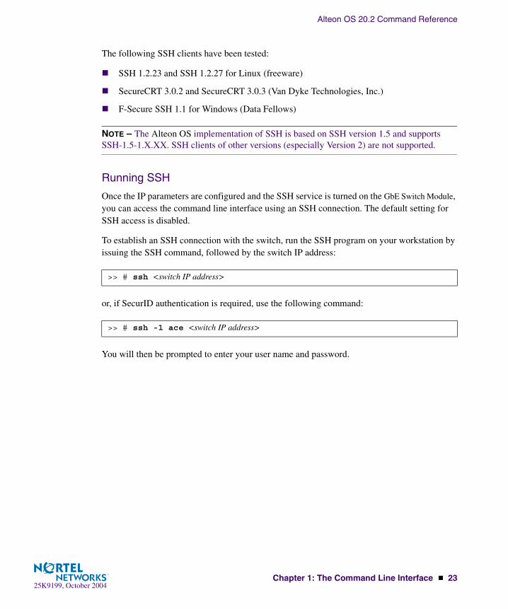
The following SSH clients have been tested:
� SSH 1.2.23 and SSH 1.2.27 for Linux (freeware)
� SecureCRT 3.0.2 and SecureCRT 3.0.3 (Van Dyke Technologies, Inc.)
� F-Secure SSH 1.1 for Windows (Data Fellows)
NOTE – The Alteon OS implementation of SSH is based on SSH version 1.5 and supports SSH-1.5-1.X.XX. SSH clients of other versions (especially Version 2) are not supported.
Running SSH
Once the IP parameters are configured and the SSH service is turned on the GbE Switch Module, you can access the command line interface using an SSH connection. The default setting for SSH access is disabled.
To establish an SSH connection with the switch, run the SSH program on your workstation by issuing the SSH command, followed by the switch IP address:
or, if SecurID authentication is required, use the following command:
You will then be prompted to enter your user name and password.
>> # ssh <switch IP address>
>> # ssh -1 ace <switch IP address>

Alteon OS 20.2 Command Reference
24 � Chapter 1: The Command Line Interface25K9199, October 2004
Accessing the Switch
To enable better switch management and user accountability, seven levels or classes of user access have been implemented on the GbE Switch Module. Levels of access to CLI, Web man-agement functions, and screens increase as needed to perform various switch management tasks. Conceptually, access classes are defined as follows:
� User interaction with the switch is completely passive—nothing can be changed on the GbE Switch Module. Users may display information that has no security or privacy implica-tions, such as switch statistics and current operational state information.
� Operators can only effect temporary changes on the GbE Switch Module. These changes will be lost when the switch is rebooted/reset. Operators have access to the switch man-agement features used for daily switch operations. Because any changes an operator makes are undone by a reset of the switch, operators cannot severely impact switch opera-tion.
� Administrators are the only ones that may make permanent changes to the switch configu-ration—changes that are persistent across a reboot/reset of the switch. Administrators can access switch functions to configure and troubleshoot problems on the GbE Switch Module. Because administrators can also make temporary (operator-level) changes as well, they must be aware of the interactions between temporary and permanent changes.
Access to switch functions is controlled through the use of unique surnames and passwords. Once you are connected to the switch via local Telnet, remote Telnet, or SSH, you are prompted to enter a password. The default user names/password for each access level are listed in the following table.
NOTE – It is recommended that you change default switch passwords after initial configuration and as regularly as required under your network security policies. For more information, see “Setting Passwords” on page 39.
Table 1-2 User Access Levels
User Account Description and Tasks Performed Password
User The User has no direct responsibility for switch management. He or she can view all switch status information and statistics, but cannot make any configuration changes to the switch.
user

Alteon OS 20.2 Command Reference
Chapter 1: The Command Line Interface � 2525K9199, October 2004
NOTE – With the exception of the “admin” user, access to each user level can be disabled by setting the password to an empty value. All user levels below “admin” will (by default) be ini-tially disabled (empty password) until they are enabled by the “admin” user. This is done in order to avoid inadvertently leaving the switch open to unauthorized users.
SLB Operator The SLB Operator manages Web servers and other Internet ser-vices and their loads. In addition to being able to view all switch information and statistics, the SLB Operator can enable/disable servers using the Server Load Balancing operation menu.
slboper
Layer 4 Operator The Layer 4 Operator manages traffic on the lines leading to the shared Internet services. This user currently has the same access level as the SLB operator. and the access level is reserved for future use, to provide access to operational com-mands for operators managing traffic on the line leading to the shared Internet services.
l4oper
Operator The Operator manages all functions of the switch. In addition to SLB Operator functions, the Operator can reset ports or the entire switch.
oper
SLB Administrator The SLB Administrator configures and manages Web servers and other Internet services and their loads. In addition to SLB Operator functions, the SLB Administrator can configure parameters on the Server Load Balancing menus, with the exception of not being able to configure filters or bandwidth management.
slbadmin
Layer 4Administrator
The Layer 4 Administrator configures and manages traffic on the lines leading to the shared Internet services. In addition to SLB Administrator functions, the Layer 4 Administrator can configure all parameters on the Server Load Balancing menus, including filters and bandwidth management.
l4admin
Administrator The superuser Administrator has complete access to all menus, information, and configuration commands on the GbE Switch Module, including the ability to change both the user and administrator passwords.
admin
Table 1-2 User Access Levels
User Account Description and Tasks Performed Password

Alteon OS 20.2 Command Reference
26 � Chapter 1: The Command Line Interface25K9199, October 2004
Setup Versus CLI
Once the administrator password is verified, you are given complete access to the switch. If the switch is still set to its factory default configuration, the system will ask whether you wish to run Setup (see Chapter 2, “First-Time Configuration”), a utility designed to help you through the first-time configuration process. If the switch has already been configured, the Main Menu of the CLI is displayed instead.
The following table shows the Main Menu with administrator privileges.
NOTE – If you are accessing a user account or Layer 4 administrator account, some menu options will not be available.
Command Line History and Editing
For a description of global commands, shortcuts, and command line editing functions, see “Menu Basics” on page 45.”
Idle Timeout
By default, the switch will disconnect your Telnet session after five minutes of inactivity. This function is controlled by the idle timeout parameter, which can be set from 1 to 60 minutes. For information on changing this parameter, see “System Configuration” on page 167.
[Main Menu] info - Information Menu stats - Statistics Menu cfg - Configuration Menu oper - Operations Command Menu boot - Boot Options Menu maint - Maintenance Menu diff - Show pending config changes [global command] apply - Apply pending config changes [global command] save - Save updated config to FLASH [global command] revert - Revert pending or applied changes [global command] exit - Exit [global command, always available]

25K9199, October 200427
CHAPTER 2First-Time Configuration
To help with the initial process of configuring your switch, the Alteon OS software includes a Setup utility. The Setup utility prompts you step-by-step to enter all the necessary information for basic configuration of the switch. This chapter describes how to use the Setup utility and how to change system passwords. Before you run Setup, you must first connection to the switch (see Chapter 1, “Connecting to the Switch”).
Using the Setup Utility
Whenever you log in as the system administrator under the factory default configuration, you are asked whether you wish to run the Setup utility. Setup can also be activated manually from the command line interface any time after login.
Information Needed For SetupSetup requests the following information:
� Basic system information
� Date & time
� Whether to use BOOTP or not
� Whether to use Spanning Tree Group or not
� Optional configuration for each port
� Speed, duplex, flow control, and negotiation mode (as appropriate)
� Whether to use VLAN tagging or not (as appropriate)
� Optional configuration for each VLAN
� Name of VLAN
� Which ports are included in the VLAN
Alteon OS 20.2 Command Reference
28 � Chapter 2: First-Time Configuration25K9199, October 2004
� Optional configuration of IP parameters
� IP address, subnet mask, and VLAN for each IP interface
� IP addresses for up to four default gateways
� Destination, subnet mask, and gateway IP address for each IP static route
� Whether IP forwarding is enabled or not
� Whether the RIP supply is enabled or not
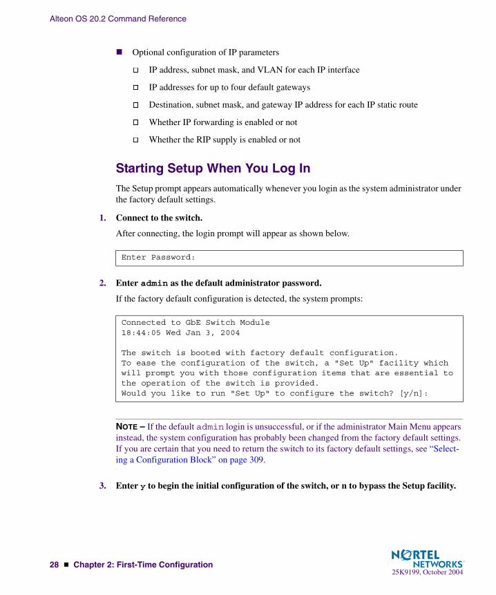
Starting Setup When You Log InThe Setup prompt appears automatically whenever you login as the system administrator under the factory default settings.
1. Connect to the switch.
After connecting, the login prompt will appear as shown below.
2. Enter admin as the default administrator password.
If the factory default configuration is detected, the system prompts:
NOTE – If the default admin login is unsuccessful, or if the administrator Main Menu appears instead, the system configuration has probably been changed from the factory default settings. If you are certain that you need to return the switch to its factory default settings, see “Select-ing a Configuration Block” on page 309.
3. Enter y to begin the initial configuration of the switch, or n to bypass the Setup facility.
Enter Password:
Connected to GbE Switch Module18:44:05 Wed Jan 3, 2004
The switch is booted with factory default configuration.To ease the configuration of the switch, a "Set Up" facility whichwill prompt you with those configuration items that are essential to the operation of the switch is provided.Would you like to run "Set Up" to configure the switch? [y/n]:
Alteon OS 20.2 Command Reference
Chapter 2: First-Time Configuration � 2925K9199, October 2004
Stopping and Restarting Setup Manually
Stopping SetupTo abort the Setup utility, press <Ctrl-C> during any Setup question. When you abort Setup, the system will prompt:
Enter n to abort Setup, or y to restart the Setup program at the beginning.
Restarting SetupYou can restart the Setup utility manually at any time by entering the following command at the administrator prompt:
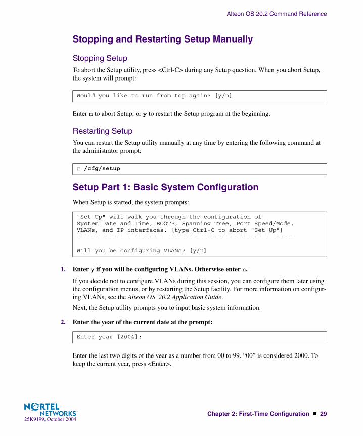
Setup Part 1: Basic System ConfigurationWhen Setup is started, the system prompts:
1. Enter y if you will be configuring VLANs. Otherwise enter n.
If you decide not to configure VLANs during this session, you can configure them later using the configuration menus, or by restarting the Setup facility. For more information on configur-ing VLANs, see the Alteon OS 20.2 Application Guide.
Next, the Setup utility prompts you to input basic system information.
2. Enter the year of the current date at the prompt:
Enter the last two digits of the year as a number from 00 to 99. “00” is considered 2000. To keep the current year, press <Enter>.
Would you like to run from top again? [y/n]
# /cfg/setup
"Set Up" will walk you through the configuration ofSystem Date and Time, BOOTP, Spanning Tree, Port Speed/Mode,VLANs, and IP interfaces. [type Ctrl-C to abort "Set Up"]------------------------------------------------------------
Will you be configuring VLANs? [y/n]
Enter year [2004]:

Alteon OS 20.2 Command Reference
30 � Chapter 2: First-Time Configuration25K9199, October 2004
NOTE – When the GbE Switch Module is reset, the date and time to revert to default values. Use /cfg/sys/date and /cfg/sys/time to reenter the current date and time.
The system displays the date and time settings:
3. Enter the month of the current system date at the prompt:
Enter the month as a number from 1 to 12. To keep the current month, press <Enter>.
4. Enter the day of the current date at the prompt:
Enter the date as a number from 1 to 31. To keep the current day, press <Enter>.
5. Enter the hour of the current system time at the prompt:
Enter the hour as a number from 00 to 23. To keep the current hour, press <Enter>.
6. Enter the minute of the current time at the prompt:
Enter the minute as a number from 00 to 59. To keep the current minute, press <Enter>.
7. Enter the seconds of the current time at the prompt:
Enter the seconds as a number from 00 to 59. To keep the current second, press <Enter>.
The system displays the date and time settings:
System clock set to 18:55:36 Wed Jan 3, 2004.
System Date:Enter month [1]:
Enter day [3]:
System Time:Enter hour in 24-hour format [18]:
Enter minutes [55]:
Enter seconds [37]:
System clock set to 8:55:36 Wed Jan 3, 2004.
Alteon OS 20.2 Command Reference
Chapter 2: First-Time Configuration � 3125K9199, October 2004
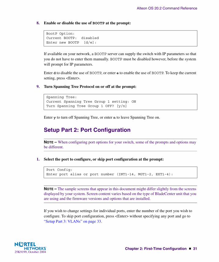
8. Enable or disable the use of BOOTP at the prompt:
If available on your network, a BOOTP server can supply the switch with IP parameters so that you do not have to enter them manually. BOOTP must be disabled however, before the system will prompt for IP parameters.
Enter d to disable the use of BOOTP, or enter e to enable the use of BOOTP. To keep the current setting, press <Enter>.
9. Turn Spanning Tree Protocol on or off at the prompt:
Enter y to turn off Spanning Tree, or enter n to leave Spanning Tree on.
Setup Part 2: Port Configuration
NOTE – When configuring port options for your switch, some of the prompts and options may be different.
1. Select the port to configure, or skip port configuration at the prompt:
NOTE – The sample screens that appear in this document might differ slightly from the screens displayed by your system. Screen content varies based on the type of BladeCenter unit that you are using and the firmware versions and options that are installed.
If you wish to change settings for individual ports, enter the number of the port you wish to configure. To skip port configuration, press <Enter> without specifying any port and go to “Setup Part 3: VLANs” on page 33.
BootP Option:Current BOOTP: disabledEnter new BOOTP [d/e]:
Spanning Tree:Current Spanning Tree Group 1 setting: ONTurn Spanning Tree Group 1 OFF? [y/n]
Port Config:Enter port alias or port number (INT1-14, MGT1-2, EXT1-4):

Alteon OS 20.2 Command Reference
32 � Chapter 2: First-Time Configuration25K9199, October 2004
2. Configure Gigabit Ethernet port flow parameters.
If you selected a port that has a Gigabit Ethernet connector, the system prompts:
Enter rx to enable receive flow control, tx for transmit flow control, both to enable both, or none to turn flow control off for the port. To keep the current setting, press <Enter>.
3. Configure Gigabit Ethernet port autonegotiation mode.
If you selected a port that has a Gigabit Ethernet connector, the system prompts:
Enter on to enable port autonegotiation, off to disable it, or press <Enter> to keep the current setting.
4. If configuring VLANs, enable or disable VLAN tagging for the port.
If you have selected to configure VLANs back in Part 1, the system prompts:
Enter d to disable VLAN tagging for the port or enter e to enable VLAN tagging for the port. To keep the current setting, press <Enter>.
5. The system prompts you to configure the next port:
When you are through configuring ports, press <Enter> without specifying any port. Other-wise, repeat the steps in this section.
Gig Link Configuration:Port Flow Control:Current Port EXT1 flow control setting: bothEnter new value ["rx"/"tx"/"both"/"none"]:
Port Auto Negotiation:Current Port EXT1 autonegotiation: onEnter new value ["on"/"off"]:
Port VLAN tagging config (tagged port can be a member of multiple VLANs)Current TAG support: disabledEnter new TAG support [d/e]:
Enter port alias or port number (INT1-14, MGT1-2, EXT1-4):

Alteon OS 20.2 Command Reference
Chapter 2: First-Time Configuration � 3325K9199, October 2004
Setup Part 3: VLANsIf you chose to skip VLANs configuration back in Part 1, skip to “Setup Part 4: IP Configura-tion” on page 34.
1. Select the VLAN to configure, or skip VLAN configuration at the prompt:
If you wish to change settings for individual VLANs, enter the number of the VLAN you wish to configure. To skip VLAN configuration, press <Enter> without typing a VLAN number and go to “Setup Part 4: IP Configuration” on page 34.
2. Enter the new VLAN name at the prompt:
Entering a new VLAN name is optional. To use the pending new VLAN name, press <Enter>.
3. Configure jumbo frame support for the VLAN:
4. Enter the VLAN port numbers:
Enter each port, by port number or port alias, and confirm placement of the port into this VLAN. When you are finished adding ports to this VLAN, press <Enter> without specifying any port.
5. Configure Spanning Tree Group membership for the VLAN:
VLAN Config:Enter VLAN number from 2 to 4095, NULL at end:
VLAN is newly created.Pending new VLAN name: VLAN 2Enter new VLAN name:
VLAN Jumbo Frame Support:Current jumbo frame support: disabledEnter new jumbo frame support [d/e]:
Define Ports in VLAN:Current VLAN 2: emptyEnter ports one per line, NULL at end:
Spanning Tree Group membership:Enter new Spanning Tree Group index [1-16]:
Alteon OS 20.2 Command Reference
34 � Chapter 2: First-Time Configuration25K9199, October 2004
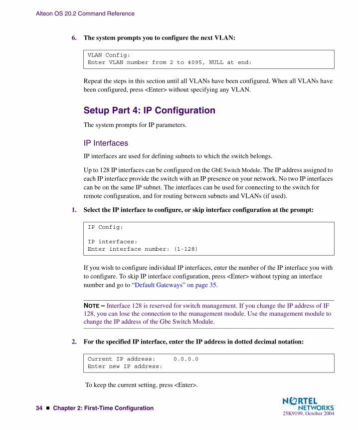
6. The system prompts you to configure the next VLAN:
Repeat the steps in this section until all VLANs have been configured. When all VLANs have been configured, press <Enter> without specifying any VLAN.
Setup Part 4: IP ConfigurationThe system prompts for IP parameters.
IP Interfaces
IP interfaces are used for defining subnets to which the switch belongs.
Up to 128 IP interfaces can be configured on the GbE Switch Module. The IP address assigned to each IP interface provide the switch with an IP presence on your network. No two IP interfaces can be on the same IP subnet. The interfaces can be used for connecting to the switch for remote configuration, and for routing between subnets and VLANs (if used).
1. Select the IP interface to configure, or skip interface configuration at the prompt:
If you wish to configure individual IP interfaces, enter the number of the IP interface you with to configure. To skip IP interface configuration, press <Enter> without typing an interface number and go to “Default Gateways” on page 35.
NOTE – Interface 128 is reserved for switch management. If you change the IP address of IF 128, you can lose the connection to the management module. Use the management module to change the IP address of the Gbe Switch Module.
2. For the specified IP interface, enter the IP address in dotted decimal notation:
To keep the current setting, press <Enter>.
VLAN Config:Enter VLAN number from 2 to 4095, NULL at end:
IP Config:
IP interfaces:Enter interface number: (1-128)
Current IP address: 0.0.0.0Enter new IP address:

Alteon OS 20.2 Command Reference
Chapter 2: First-Time Configuration � 3525K9199, October 2004
3. At the prompt, enter the IP subnet mask in dotted decimal notation:
To keep the current setting, press <Enter>.
4. If configuring VLANs, specify a VLAN for the interface.
This prompt appears if you selected to configure VLANs back in Part 1:
Enter the number for the VLAN to which the interface belongs, or press <Enter> without spec-ifying a VLAN number to accept the current setting.
5. At the prompt, enter y to enable the IP interface, or n to leave it disabled:
6. The system prompts you to configure another interface:
Repeat the steps in this section until all IP interfaces have been configured. When all interfaces have been configured, press <Enter> without specifying any interface number.
Default Gateways
1. At the prompt, select a default gateway for configuration, or skip default gateway config-uration:
Enter the number for the default gateway to be configured. To skip default gateway configura-tion, press <Enter> without typing a gateway number and go to “IP Routing” on page 36.
Current subnet mask: 0.0.0.0Enter new subnet mask:
Current VLAN: 1Enter new VLAN:
Enable IP interface? [y/n]
Enter interface number: (1-128)
IP default gateways:Enter default gateway number: (1-132)

Alteon OS 20.2 Command Reference
36 � Chapter 2: First-Time Configuration25K9199, October 2004
2. At the prompt, enter the IP address for the selected default gateway:
Enter the IP address in dotted decimal notation, or press <Enter> without specifying an address to accept the current setting.
3. At the prompt, enter y to enable the default gateway, or n to leave it disabled:
4. The system prompts you to configure another default gateway:
Repeat the steps in this section until all default gateways have been configured. When all default gateways have been configured, press <Enter> without specifying any number.
IP Routing
When IP interfaces are configured for the various subnets attached to your switch, IP routing between them can be performed entirely within the switch. This eliminates the need to send inter-subnet communication to an external router device. Routing on more complex networks, where subnets may not have a direct presence on the GbE Switch Module, can be accomplished through configuring static routes or by letting the switch learn routes dynamically.
This part of the Setup program prompts you to configure the various routing parameters.
1. At the prompt, enable or disable forwarding for IP Routing:
Enter y to enable IP forwarding. To disable IP forwarding, enter n and proceed to Step 2.To keep the current setting, press <Enter>.
2. At the prompt, enable or disable the RIP supply:
Current IP address: 0.0.0.0Enter new IP address:
Enable default gateway? [y/n]
Enter default gateway number: (1-132)
Enable IP forwarding? [y/n]
Enable RIP supply? [y/n]

Alteon OS 20.2 Command Reference
Chapter 2: First-Time Configuration � 3725K9199, October 2004
Setup Part 5: Final Steps
1. When prompted, decide whether to restart Setup or continue:
Enter y to restart the Setup utility from the beginning, or n to continue.
2. When prompted, decide whether you wish to review the configuration changes:
Enter y to review the changes made during this session of the Setup utility. Enter n to continue without reviewing the changes. We recommend that you review the changes.
3. Next, decide whether to apply the changes at the prompt:
Enter y to apply the changes, or n to continue without applying. Changes are normally applied.
4. At the prompt, decide whether to make the changes permanent:
Enter y to save the changes to flash. Enter n to continue without saving the changes. Changes are normally saved at this point.
5. If you do not apply or save the changes, the system prompts whether to abort them:
Enter y to discard the changes. Enter n to return to the “Apply the changes?” prompt.
NOTE – After initial configuration is complete, it is recommended that you change the default passwords as shown in “Setting Passwords” on page 39.
Would you like to run from top again? [y/n]
Review the changes made? [y/n]
Apply the changes? [y/n]
Save changes to flash? [y/n]
Abort all changes? [y/n]

Alteon OS 20.2 Command Reference
38 � Chapter 2: First-Time Configuration25K9199, October 2004
Optional Setup for SNMP Support
NOTE – This step is optional. Perform this procedure only if you are planning on using SNMP-based tools.
1. Enable SNMP and select one of the options.
2. Set SNMP read or write community string. By default, they are public and private respectively.
3. Apply and save configuration if you are not configuring the switch with Telnet support. Otherwise apply and save after “Optional Setup for Telnet Support” on page 38.
Optional Setup for Telnet Support
NOTE – This step is optional. Perform this procedure only if you are planning on connecting to the GbE Switch Module through a remote Telnet connection.
1. Telnet is enabled by default. To change the setting, use the following command:
2. Apply and save SNMP and /or telnet configuration(s).
If your network uses Routing Interface Protocol (RIP), enter y to enable the RIP supply. Other-wise, enter n to disable it. When RIP is enabled, RIP listen is set by default.
>> # /cfg/sys/snmp dis|read|write
>> # /cfg/snmp/rcomm|wcomm
>> System# apply>> System# save
>> # /cfg/sys/tnet
>> System# apply>> System# save

Alteon OS 20.2 Command Reference
Chapter 2: First-Time Configuration � 3925K9199, October 2004
Setting Passwords
It is recommended that you change the user and administrator passwords after initial configu-ration and as regularly as required under your network security policies.
To change both the user password and the administrator password, you must login using the administrator password. Passwords cannot be modified from the user command mode.
NOTE – If you forget your administrator password, call your technical support representative for help using the password fix-up mode.
Changing the Default Administrator PasswordThe administrator has complete access to all menus, information, and configuration com-mands, including the ability to change both the user and administrator passwords.
The default password for the administrator account is admin. To change the default password, follow this procedure:
1. Connect to the switch and log in using the admin password.
2. From the Main Menu, use the following command to access the Configuration Menu:
The Configuration Menu is displayed.
3. From the Configuration Menu, use the following command to select the System Menu:
Main# /cfg
[Configuration Menu] sys - System-wide Parameter Menu port - Port Menu pmirr - Port Mirroring Menu l2 - Layer 2 Menu l3 - Layer 3 Menu slb - Server Load Balancing (Layer 4-7) Menu setup - Step by step configuration set up dump - Dump current configuration to script file ptcfg - Backup current configuration to tftp server gtcfg - Restore current configuration from tftp server
>> Configuration# sys

Alteon OS 20.2 Command Reference
40 � Chapter 2: First-Time Configuration25K9199, October 2004
The System Menu is displayed.
4. From the System Menu, use the following command to select the System Access Menu:
The System Access Menu is displayed.
5. Select the administrator password.
[System Menu] syslog - Syslog Menu sshd - SSH Server Menu radius - RADIUS Authentication Menu tacacs - TACACS+ Authentication Menu ntp - NTP Server Menu ssnmp - System SNMP Menu access - System Access Menu date - Set system date time - Set system time idle - Set timeout for idle CLI sessions notice - Set login notice bannr - Set login banner smtp - Set SMTP host hprompt - Enable/disable display hostname (sysName) in CLI prompt bootp - Enable/disable use of BOOTP cur - Display current system-wide parameters
>> System# access
[System Access Menu] user - User Access Control Menu (passwords) http - Enable/disable HTTP (Web) access wport - Set HTTP (Web) server port number mnet - Set management network mmask - Set management netmask snmp - Set SNMP access control tnet - Enable/disable Telnet access tnport - Set Telnet server port number cur - Display current system access configuration
System Access# user/admpw

Alteon OS 20.2 Command Reference
Chapter 2: First-Time Configuration � 4125K9199, October 2004
6. Enter the current administrator password at the prompt:
NOTE – If you forget your administrator password, call your technical support representative for help using the password fix-up mode.
7. Enter the new administrator password at the prompt:
8. Enter the new administrator password, again, at the prompt:
9. Apply and save your change by entering the following commands:
Changing the Default User PasswordThe user login has limited control of the switch. Through a user account, you can view switch information and statistics, but you can’t make configuration changes.
The default password for the user account is user. This password cannot be changed from the user account. Only the administrator has the ability to change passwords, as shown in the fol-lowing procedure.
1. Connect to the switch and log in using the admin password.
2. From the Main Menu, use the following command to access the Configuration Menu:
3. From the Configuration Menu, use the following command to select the System Menu:
Changing ADMINISTRATOR password; validation required...Enter current administrator password:
Enter new administrator password:
Re-enter new administrator password:
System# applySystem# save
Main# cfg
>> Configuration# sys

Alteon OS 20.2 Command Reference
42 � Chapter 2: First-Time Configuration25K9199, October 2004
4. From the System Menu, use the following command to select the System Access Menu:
5. Select the user password.
6. Enter the current administrator password at the prompt.
Only the administrator can change the user password. Entering the administrator password confirms your authority.
7. Enter the new user password at the prompt:
8. Enter the new user password, again, at the prompt:
9. Apply and save your changes:
Changing the Default Layer 4 Administrator PasswordThe Layer 4 administrator has limited control of the switch. Through a Layer 4 administrator account, you can view all switch information and statistics, but can configure changes only on the Server Load Balancing menus.
The default password for the Layer 4 administrator account is l4admin. To change the default password, follow this procedure:
1. Connect to the switch and log in using the administrator account.
To change any switch password, you must login using the administrator password. Passwords cannot be modified from the Layer 4 administrator account or the user account.
>> System# access
System# user/usrpw
Changing USER password; validation required...Enter current administrator password:
Enter new user password:
Re-enter new user password:
System# applySystem# save

Alteon OS 20.2 Command Reference
Chapter 2: First-Time Configuration � 4325K9199, October 2004
2. From the Main Menu, use the following command to access the System Menu:
3. Select the Layer 4 administrator password:
4. Enter the current administrator password (not the Layer 4 administrator password) at the prompt:
NOTE – If you forget your administrator password, call your technical support representative for help using the password fix-up mode.
5. Enter the new Layer 4 administrator password at the prompt:
6. Enter the new administrator password, again, at the prompt:
7. Apply and save your change by entering the following commands:
Main# /cfg/sys/access/user
System# l4apw
Changing L4 ADMINISTRATOR password; validation required...Enter current administrator password:
Enter new L4 administrator password:
Re-enter new L4 administrator password:
System Access# applySystem Access# save

Alteon OS 20.2 Command Reference
44 � Chapter 2: First-Time Configuration25K9199, October 2004
25K9199, October 200445
CHAPTER 3Menu Basics
The GbE Switch Module’s Command Line Interface (CLI) is used for viewing switch informa-tion and statistics. In addition, the administrator can use the CLI for performing all levels of switch configuration.
To make the CLI easy to use, the various commands have been logically grouped into a series of menus and sub-menus. Each menu displays a list of commands and/or sub-menus that are available, along with a summary of what each command will do. Below each menu is a prompt where you can enter any command appropriate to the current menu.
This chapter describes the Main Menu commands, and provides a list of commands and short-cuts that are commonly available from all the menus within the CLI.
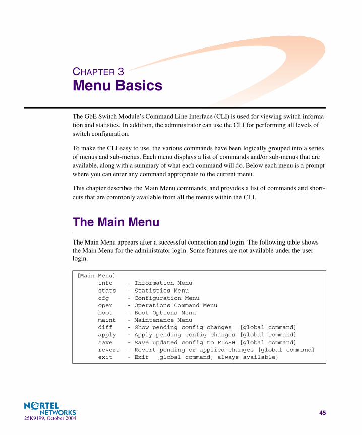
The Main Menu
The Main Menu appears after a successful connection and login. The following table shows the Main Menu for the administrator login. Some features are not available under the user login.
[Main Menu] info - Information Menu stats - Statistics Menu cfg - Configuration Menu oper - Operations Command Menu boot - Boot Options Menu maint - Maintenance Menu diff - Show pending config changes [global command] apply - Apply pending config changes [global command] save - Save updated config to FLASH [global command] revert - Revert pending or applied changes [global command] exit - Exit [global command, always available]

Alteon OS 20.2 Command Reference
46 � Chapter 3: Menu Basics25K9199, October 2004
Menu Summary
� Information Menu
Provides sub-menus for displaying information about the current status of the switch: from basic system settings to VLANs, Layer 4 settings, and more.
� Statistics Menu
Provides sub-menus for displaying switch performance statistics. Included are port, IF, IP, ICMP, TCP, UDP, SNMP, routing, ARP, DNS, VRRP, and Layer 4 statistics.
� Configuration Menu
This menu is available only from an administrator login. It includes sub-menus for config-uring every aspect of the switch. Changes to configuration are not active until explicitly applied. Changes can be saved to non-volatile memory.
� Operations Command Menu
Operations-level commands are used for making immediate and temporary changes to switch configuration. This menu is used for bringing ports temporarily in and out of ser-vice, performing port mirroring, and enabling or disabling Server Load Balancing func-tions. It is also used for activating or deactivating optional software packages.
� Boot Options Menu
This menu is used for upgrading switch software, selecting configuration blocks, and for resetting the switch when necessary.
� Maintenance Menu
This menu is used for debugging purposes, enabling you to generate a dump of the critical state information in the switch, and to clear entries in the forwarding database and the ARP and routing tables.
Alteon OS 20.2 Command Reference
Chapter 3: Menu Basics � 4725K9199, October 2004
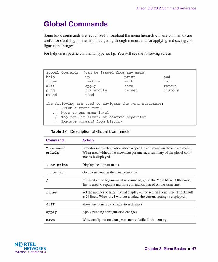
Global CommandsSome basic commands are recognized throughout the menu hierarchy. These commands are useful for obtaining online help, navigating through menus, and for applying and saving con-figuration changes.
For help on a specific command, type help. You will see the following screen:
.
Global Commands: [can be issued from any menu]help up print pwdlines verbose exit quitdiff apply save revertping traceroute telnet historypushd popd
The following are used to navigate the menu structure: . Print current menu .. Move up one menu level / Top menu if first, or command separator ! Execute command from history
Table 3-1 Description of Global Commands
Command Action
? command or help
Provides more information about a specific command on the current menu. When used without the command parameter, a summary of the global com-mands is displayed.
. or print Display the current menu.
.. or up Go up one level in the menu structure.
/ If placed at the beginning of a command, go to the Main Menu. Otherwise, this is used to separate multiple commands placed on the same line.
lines Set the number of lines (n) that display on the screen at one time. The default is 24 lines. When used without a value, the current setting is displayed.
diff Show any pending configuration changes.
apply Apply pending configuration changes.
save Write configuration changes to non-volatile flash memory.

Alteon OS 20.2 Command Reference
48 � Chapter 3: Menu Basics25K9199, October 2004
revert Remove pending configuration changes between “apply” commands. Use this command to restore configuration parameters set since last “apply” com-mand.
exit or quit Exit from the command line interface and log out.
ping Use this command to verify station-to-station connectivity across the net-work. The format is as follows: ping <host name>|<IP address> [tries (1-32)> [msec delay]] [-m|-mgmt|-d|-data]Where IP address is the hostname or IP address of the device, tries (optional) is the number of attempts (1-32), msec delay (optional) is the number of mil-liseconds between attempts. By default, the -d or -data option for net-work ports is in effect. If the management port is used, specify the -m or-mgmt option. The DNS parameters must be configured if specifying host-names (see “Domain Name System Configuration” on page 234).
traceroute Use this command to identify the route used for station-to-station connectiv-ity across the network. The format is as follows:
traceroute <host name>| <IP address> [<max-hops (1-32)> [msec delay]] [-m|-mgmt|-d|-data]Where IP address is the hostname or IP address of the target station, max-hops (optional) is the maximum distance to trace (1-16 devices), and delay (optional) is the number of milliseconds for wait for the response. By default, the -d or -data option for network ports is in effect. If the management port is used, specify the -m or -mgmt option. As with ping, the DNS parameters must be configured if specifying hostnames.
pwd Display the command path used to reach the current menu.
verbose n Sets the level of information displayed on the screen:0 =Quiet: Nothing appears except errors—not even prompts.1 =Normal: Prompts and requested output are shown, but no menus.2 =Verbose: Everything is shown.When used without a value, the current setting is displayed.
telnet This command is used to telnet out of the switch. The format is as follows:<hostname>|<IP address> [port] [-m|-mgmt|-d|-data].Where IP address is the hostname or IP address of the device. By default, the -d or -data option for network ports is in effect. If the management port is used, specify the -m or -mgmt option.
history This command brings up the history of the last 10 commands.
Table 3-1 Description of Global Commands
Command Action
Alteon OS 20.2 Command Reference
Chapter 3: Menu Basics � 4925K9199, October 2004
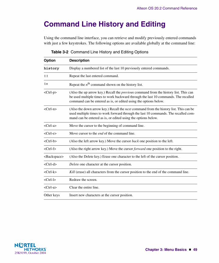
Command Line History and Editing
Using the command line interface, you can retrieve and modify previously entered commands with just a few keystrokes. The following options are available globally at the command line:
Table 3-2 Command Line History and Editing Options
Option Description
history Display a numbered list of the last 10 previously entered commands.
!! Repeat the last entered command.
!n Repeat the nth command shown on the history list.
<Ctrl-p> (Also the up arrow key.) Recall the previous command from the history list. This can be used multiple times to work backward through the last 10 commands. The recalled command can be entered as is, or edited using the options below.
<Ctrl-n> (Also the down arrow key.) Recall the next command from the history list. This can be used multiple times to work forward through the last 10 commands. The recalled com-mand can be entered as is, or edited using the options below.
<Ctrl-a> Move the cursor to the beginning of command line.
<Ctrl-e> Move cursor to the end of the command line.
<Ctrl-b> (Also the left arrow key.) Move the cursor back one position to the left.
<Ctrl-f> (Also the right arrow key.) Move the cursor forward one position to the right.
<Backspace> (Also the Delete key.) Erase one character to the left of the cursor position.
<Ctrl-d> Delete one character at the cursor position.
<Ctrl-k> Kill (erase) all characters from the cursor position to the end of the command line.
<Ctrl-l> Redraw the screen.
<Ctrl-u> Clear the entire line.
Other keys Insert new characters at the cursor position.

Alteon OS 20.2 Command Reference
50 � Chapter 3: Menu Basics25K9199, October 2004
Command Line Interface Shortcuts
Command StackingAs a shortcut, you can type multiple commands on a single line, separated by forward slashes (/). You can connect as many commands as required to access the menu option that you want. For example, the keyboard shortcut to access the Spanning Tree Port Configuration Menu from the Main# prompt is as follows:
Command AbbreviationMost commands can be abbreviated by entering the first characters which distinguish the com-mand from the others in the same menu or sub-menu. For example, the command shown above could also be entered as follows:
Tab CompletionBy entering the first letter of a command at any menu prompt and hitting <Tab>, the CLI will display all commands or options in that menu that begin with that letter. Entering additional letters will further refine the list of commands or options displayed. If only one command fits the input text when <Tab> is pressed, that command will be supplied on the command line, waiting to be entered. If the <Tab> key is pressed without any input on the command line, the currently active menu will be displayed.
Main# cfg/stg/port
Main# c/st/p

25K9199, October 200451
CHAPTER 4The Information Menu
You can view configuration information for the switch in both the user and administrator command modes. This chapter discusses how to use the command line interface to display switch infor-mation.
/infoInformation Menu
The information provided by each menu option is briefly described in Table 4-1 on page 51, with pointers to where detailed information can be found.
[Information Menu] sys - System Information Menu l2 - Layer 2 Information Menu l3 - Layer 3 Information Menu slb - Layer 4-7 Information Menu link - Show link status port - Show port information dump - Dump all information
Table 4-1 Information Menu Options (/info)
Command Syntax and Usage
sys
Displays the System Information Menu. For details, see page 53.
l2
Displays the Layer 2 Information Menu. For details, see page 56.
l3
Displays the Layer 3 Information Menu. For details, see page 66.
slb
Displays the Layer 4 Information Menu. For details, see page 84.

Alteon OS 20.2 Command Reference
52 � Chapter 4: The Information Menu25K9199, October 2004
link
Displays configuration information about each port, including:
� Port alias� Port speed (10, 100, 10/100, or 1000)� Duplex mode (half, full, or auto)� Flow control for transmit and receive (no, yes, or auto)� Link status (up or down)For details, see page 91.
port
Displays port status information, including:
� Port alias� Whether the port uses VLAN Tagging or not � Port VLAN ID (PVID)� Port name� VLAN membershipFor details, see page 92.
dump
Dumps all switch information available from the Information Menu (10K or more, depending on your configuration).
If you want to capture dump data to a file, set your communication software on your workstation to capture session data prior to issuing the dump commands.
Table 4-1 Information Menu Options (/info)
Command Syntax and Usage

Alteon OS 20.2 Command Reference
Chapter 4: The Information Menu � 5325K9199, October 2004
/info/sysSystem Information
The information provided by each menu option is briefly described in Table 4-2 on page 53, with pointers to where detailed information can be found.
[System Menu] general - Show general system information log - Show last 30 syslog messages dump - Dump all system information
Table 4-2 System Menu Options (/info/sys)
Command Syntax and Usage
general
Displays system information, including:
� System date and time� Switch model name and number� Switch name and location� Time of last boot� MAC address of the switch management processor� IP address of IP interface #1� Hardware version and part number� Software image file and version number� Configuration name� Log-in banner, if one is configuredFor details, see page 54.
log
Displays 30 most recent syslog messages. For details, see page 55.
dump
Dumps all switch information available from the Information Menu (10K or more, depending on your configuration).

Alteon OS 20.2 Command Reference
54 � Chapter 4: The Information Menu25K9199, October 2004
/info/sys/generalGeneral System Information
NOTE – The display of temperature will come up only if the temperature of any of the sensors exceeds the temperature threshold. There will be a warning from the software if any of the sen-sors exceeds this temperature threshold. The switch will shut down if the power supply over-heats.
System information includes:
� System date and time
� Switch model
� Switch name and location
� Time of last boot
� MAC address of the switch management processor
� IP address of IP interface #1
� Hardware version and part number
� Software image file and version number
� Configuration name
� Log-in banner, if one is configured
System Information at 0:57:36 Thu Jul 1, 2004
Layer 2-7 Gigabit Ethernet Switch Module for IBM eServer BladeCenter
Switch is up 5 days, 1 hour, 1 minute and 21 seconds.Last boot: 0:01:03 Thu Jul 1, 2004 (power cycle)
MAC Address: 00:09:97:ec:e6:00 Management IP Address (if 128): 10.90.90.97Software Version 20.2.0 (FLASH image1), active configuration.
PCBA Part Number: 316210-AFAB Number: 86 Serial Number: YJIRTK3510Manufacturing Date: 5120Hardware Revision: 48PLD Firmware Version: 3.4

Alteon OS 20.2 Command Reference
Chapter 4: The Information Menu � 5525K9199, October 2004
/info/sys/logShow Last 30 Syslog Messages
Each syslog message has a criticality level associated with it, included in text form as a prefix to the log message. One of eight different prefixes is used, depending on the condition that the administrator is being notified of, as shown below.
� EMERG: indicates the system is unusable
� ALERT: Indicates action should be taken immediately
� CRIT: Indicates critical conditions
� ERR: indicates error conditions or errored operations
� WARNING: indicates warning conditions
� NOTICE: indicates a normal but significant condition
� INFO: indicates an information message
� DEBUG: indicates a debut-level message
Date Time Criticality level MessageJul 8 17:25:41 NOTICE system: link up on port INT1Jul 8 17:25:41 NOTICE system: link up on port INT8Jul 8 17:25:41 NOTICE system: link up on port INT7Jul 8 17:25:41 NOTICE system: link up on port INT2Jul 8 17:25:41 NOTICE system: link up on port INT1Jul 8 17:25:41 NOTICE system: link up on port INT4Jul 8 17:25:41 NOTICE system: link up on port INT3Jul 8 17:25:41 NOTICE system: link up on port INT6Jul 8 17:25:41 NOTICE system: link up on port INT5Jul 8 17:25:41 NOTICE system: link up on port EXT4Jul 8 17:25:41 NOTICE system: link up on port EXT1Jul 8 17:25:41 NOTICE system: link up on port EXT3Jul 8 17:25:41 NOTICE system: link up on port EXT2Jul 8 17:25:41 NOTICE system: link up on port INT3Jul 8 17:25:42 NOTICE system: link up on port INT2Jul 8 17:25:42 NOTICE system: link up on port INT4Jul 8 17:25:42 NOTICE system: link up on port INT3Jul 8 17:25:42 NOTICE system: link up on port INT6Jul 8 17:25:42 NOTICE system: link up on port INT5Jul 8 17:25:42 NOTICE system: link up on port INT1Jul 8 17:25:42 NOTICE system: link up on port INT6

Alteon OS 20.2 Command Reference
56 � Chapter 4: The Information Menu25K9199, October 2004
/info/l2Layer 2 Menu
The information provided by each menu option is briefly described in Table 4-3 on page 56, with pointers to where detailed information can be found.
[Layer 2 Menu] fdb - Forwarding Database Information Menu lacp - Link Aggregation Control Protocol Menu stg - Show STG information trunk - Show Trunk Group information vlan - Show VLAN information dump - Dump all layer 2 information
Table 4-3 Layer 2 Menu Options (/info/l2)
Command Syntax and Usage
fdb
Displays the Forwarding Database Information Menu. For details, see page 57.
lacp
Displays the Link Aggregation Control Protocol Menu. For details, see page 60.
stg
In addition to seeing if STG is enabled or disabled, you can view the following STG bridge infor-mation:
� Priority� Hello interval� Maximum age value� Forwarding delay� Aging timeYou can also see the following port-specific STG information:
� Port alias and priority� Cost� StateFor details, see page 62.
trunk
When trunk groups are configured, you can view the state of each port in the various trunk groups. For details, see page 64.

Alteon OS 20.2 Command Reference
Chapter 4: The Information Menu � 5725K9199, October 2004
/info/l2/fdbFDB Information Menu
The forwarding database (FDB) contains information that maps the media access control (MAC) address of each known device to the switch port where the device address was learned. The FDB also shows which other ports have seen frames destined for a particular MAC address.
vlan
Displays VLAN configuration information, including:
� VLAN Number� VLAN Name� Status� Port membership of the VLANFor details, see page 65.
dump
Dumps all switch information available from the Layer 2 menu (10K or more, depending on your configuration).
If you want to capture dump data to a file, set your communication software on your workstation to capture session data prior to issuing the dump commands.
[Forwarding Database Menu] find - Show a single FDB entry by MAC address port - Show FDB entries on a single port trunk - Show FDB entries on a single trunk vlan - Show FDB entries on a single VLAN refpt - Show FDB entries referenced by a single port dump - Show all FDB entries
Table 4-3 Layer 2 Menu Options (/info/l2)
Command Syntax and Usage
Alteon OS 20.2 Command Reference
58 � Chapter 4: The Information Menu25K9199, October 2004
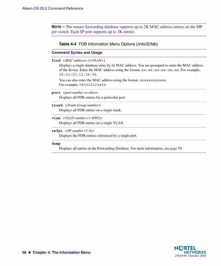
NOTE – The master forwarding database supports up to 2K MAC address entries on the MP per switch. Each SP port supports up to 1K entries.
Table 4-4 FDB Information Menu Options (/info/l2/fdb)
Command Syntax and Usage
find <MAC address> [<VLAN>]Displays a single database entry by its MAC address. You are prompted to enter the MAC address of the device. Enter the MAC address using the format, xx:xx:xx:xx:xx:xx. For example, 08:00:20:12:34:56.
You can also enter the MAC address using the format, xxxxxxxxxxxx. For example, 080020123456.
port <port number or alias>Displays all FDB entries for a particular port.
trunk <Trunk Group number>Displays all FDB entries on a single trunk.
vlan <VLAN number (1-4095)>Displays all FDB entries on a single VLAN.
refpt <SP number (1-4)>Displays the FDB entries referenced by a single port.
dump
Displays all entries in the Forwarding Database. For more information, see page 59.
Alteon OS 20.2 Command Reference
Chapter 4: The Information Menu � 5925K9199, October 2004
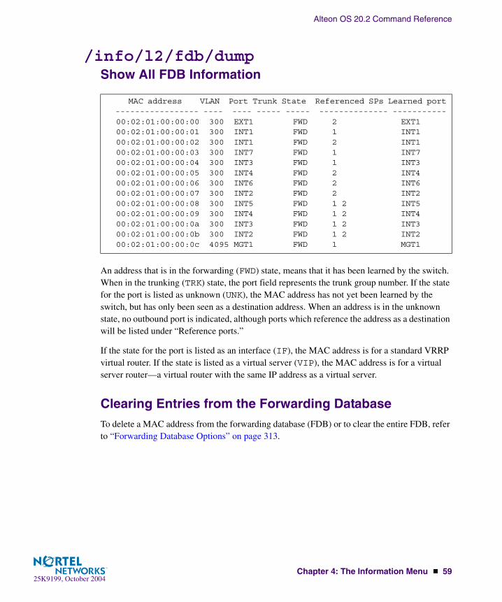
/info/l2/fdb/dumpShow All FDB Information
An address that is in the forwarding (FWD) state, means that it has been learned by the switch. When in the trunking (TRK) state, the port field represents the trunk group number. If the state for the port is listed as unknown (UNK), the MAC address has not yet been learned by the switch, but has only been seen as a destination address. When an address is in the unknown state, no outbound port is indicated, although ports which reference the address as a destination will be listed under “Reference ports.”
If the state for the port is listed as an interface (IF), the MAC address is for a standard VRRP virtual router. If the state is listed as a virtual server (VIP), the MAC address is for a virtual server router—a virtual router with the same IP address as a virtual server.
Clearing Entries from the Forwarding DatabaseTo delete a MAC address from the forwarding database (FDB) or to clear the entire FDB, refer to “Forwarding Database Options” on page 313.
MAC address VLAN Port Trunk State Referenced SPs Learned port ----------------- ---- ---- ----- ----- -------------- ----------- 00:02:01:00:00:00 300 EXT1 FWD 2 EXT1 00:02:01:00:00:01 300 INT1 FWD 1 INT1 00:02:01:00:00:02 300 INT1 FWD 2 INT1 00:02:01:00:00:03 300 INT7 FWD 1 INT7 00:02:01:00:00:04 300 INT3 FWD 1 INT3 00:02:01:00:00:05 300 INT4 FWD 2 INT4 00:02:01:00:00:06 300 INT6 FWD 2 INT6 00:02:01:00:00:07 300 INT2 FWD 2 INT2 00:02:01:00:00:08 300 INT5 FWD 1 2 INT5 00:02:01:00:00:09 300 INT4 FWD 1 2 INT4 00:02:01:00:00:0a 300 INT3 FWD 1 2 INT3 00:02:01:00:00:0b 300 INT2 FWD 1 2 INT2 00:02:01:00:00:0c 4095 MGT1 FWD 1 MGT1

Alteon OS 20.2 Command Reference
60 � Chapter 4: The Information Menu25K9199, October 2004
/info/l2/lacpLink Aggregation Control Protocol menu
Use these commands to display LACP status information about each port on a GbE Switch Mod-
ule.
/info/l2/lacp/dumpLink Aggregation Control Protocol
LACP dump includes the following information for each external port in the GbESM:
� lacpDisplays the port’s LACP mode (active, passive, or off)
� adminkeyDisplays the value of the port’s adminkey.
[LACP Menu] aggr - Show LACP aggregator information for the port port - Show LACP port information dump - Show all LACP ports information
Table 4-5 Link Aggregation Control Protocol (/info/l2/lacp)
Command Syntax and Usage
aggr
Displays detailed information of the LACP aggregator used by the selected port.
port
Displays LACP information about the selected port.
dump
Displays a summary of LACP information. For details, see page 60.
port lacp adminkey operkey selected prio attached trunk aggr--------------------------------------------------------------EXT1 active 30 30 y 128 17 19EXT2 active 30 30 y 128 17 19EXT3 off 19 19 n 128 -- --EXT4 off 20 20 n 128 -- --
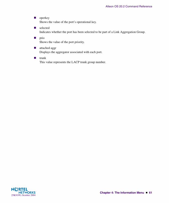
Alteon OS 20.2 Command Reference
Chapter 4: The Information Menu � 6125K9199, October 2004
� operkeyShows the value of the port’s operational key.
� selectedIndicates whether the port has been selected to be part of a Link Aggregation Group.
� prioShows the value of the port priority.
� attached aggrDisplays the aggregator associated with each port.
� trunkThis value represents the LACP trunk group number.
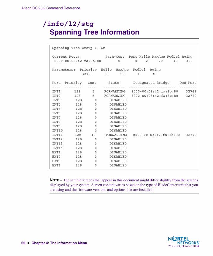
Alteon OS 20.2 Command Reference
62 � Chapter 4: The Information Menu25K9199, October 2004
/info/l2/stgSpanning Tree Information
NOTE – The sample screens that appear in this document might differ slightly from the screens displayed by your system. Screen content varies based on the type of BladeCenter unit that you are using and the firmware versions and options that are installed.
Spanning Tree Group 1: On
Current Root: Path-Cost Port Hello MaxAge FwdDel Aging 8000 00:03:42:fa:3b:80 0 0 2 20 15 300
Parameters: Priority Hello MaxAge FwdDel Aging 32768 2 20 15 300
Port Priority Cost State Designated Bridge Des Port---- -------- ---- ---------- ---------------------- --------INT1 128 5 FORWARDING 8000-00:03:42:fa:3b:80 32769INT2 128 5 FORWARDING 8000-00:03:42:fa:3b:80 32770INT3 128 0 DISABLEDINT4 128 0 DISABLEDINT5 128 0 DISABLEDINT6 128 0 DISABLEDINT7 128 0 DISABLEDINT8 128 0 DISABLEDINT9 128 0 DISABLEDINT10 128 0 DISABLEDINT11 128 10 FORWARDING 8000-00:03:42:fa:3b:80 32779INT12 128 0 DISABLEDINT13 128 0 DISABLEDINT14 128 0 DISABLEDEXT1 128 0 DISABLEDEXT2 128 0 DISABLEDEXT3 128 0 DISABLEDEXT4 128 0 DISABLED

Alteon OS 20.2 Command Reference
Chapter 4: The Information Menu � 6325K9199, October 2004
The switch software uses the IEEE 802.1d Spanning Tree Protocol (STP). In addition to seeing if STG is enabled or disabled, you can view the following STG bridge information:
� Priority
� Hello interval
� Maximum age value
� Forwarding delay
� Aging time
You can also see the following port-specific STG information:
� Slot number
� Port alias and priority
� Cost
� State
The following table describes the STG parameters.
Table 4-6 Spanning Tree Parameter Descriptions
Parameter Description
Priority (bridge) The bridge priority parameter controls which bridge on the network will become the STG root bridge.
Hello The hello time parameter specifies, in seconds, how often the root bridge transmits a configuration bridge protocol data unit (BPDU). Any bridge that is not the root bridge uses the root bridge hello value.
MaxAge The maximum age parameter specifies, in seconds, the maximum time the bridge waits without receiving a configuration bridge protocol data unit before it reconfigure the STG network.
FwdDel The forward delay parameter specifies, in seconds, the amount of time that a bridge port has to wait before it changes from learning state to forwarding state.
Aging The aging time parameter specifies, in seconds, the amount of time the bridge waits without receiving a packet from a station before removing the station from the Forwarding Database.
priority (port) The port priority parameter helps determine which bridge port becomes the designated port. In a network topology that has multiple bridge ports con-nected to a single segment, the port with the lowest port priority becomes the designated port for the segment.

Alteon OS 20.2 Command Reference
64 � Chapter 4: The Information Menu25K9199, October 2004
/info/l2/trunkTrunk Group Information
When trunk groups are configured, you can view the state of each port in the various trunk groups.
NOTE – If Spanning Tree Protocol on any port in the trunk group is set to forwarding, the remaining ports in the trunk group will also be set to forwarding.
Cost The port path cost parameter is used to help determine the designated port for a segment. Generally speaking, the faster the port, the lower the path cost. A setting of 0 indicates that the cost will be set to the appropriate default after the link speed has been auto negotiated.
State The state field shows the current state of the port. The state field can be either BLOCKING, LISTENING, LEARNING, FORWARDING, or DISABLED.
Trunk group 1, failover ena, port state: 1: STG 1 forwarding 2: STG 1 forwarding
Table 4-6 Spanning Tree Parameter Descriptions (Continued)
Parameter Description

Alteon OS 20.2 Command Reference
Chapter 4: The Information Menu � 6525K9199, October 2004
/info/l2/vlanVLAN Information
NOTE – The sample screens that appear in this document might differ slightly from the screens displayed by your system. Screen content varies based on the type of BladeCenter unit that you are using and the firmware versions and options that are installed.
This information display includes all configured VLANs and all member ports that have an active link state. Port membership is represented in slot/port format.
VLAN information includes:
� VLAN Number
� VLAN Name
� Status
� Jumbo frame support
� Port membership of the VLAN
VLAN Name Status Jumbo Ports---- -------------------------------- ------ ----- ----------------1 Default VLAN ena n EXT1 EXT32 pc03p ena n INT27 pc07f ena n INT711 pc04u ena n INT1114 8600-14 ena n INT1415 8600-15 ena n INT516 8600-16 ena n INT617 8600-17 ena n INT818 35k-1 ena n INT919 35k-2 ena n INT1020 35k-3 ena n INT1221 35k-4 ena n INT1322 pc07z ena n INT624 redlan ena n INT7300 ixiaTraffic ena n EXT1 INT12 INT134000 bpsports ena n INT3-INT64095 Mgmt VLAN ena n MGT1 MGT2

Alteon OS 20.2 Command Reference
66 � Chapter 4: The Information Menu25K9199, October 2004
/info/l3Layer 3 Menu
The information provided by each menu option is briefly described in Table 4-7 on page 66, with pointers to where detailed information can be found.
[Layer 3 Menu] route - IP Routing Information Menu arp - ARP Information Menu bgp - BGP Information Menu ospf - OSPF Routing Information Menu igmp - IGMP Information Menu ip - Show IP information vrrp - Show Virtual Router Redundancy Protocol information dump - Dump all layer 3 information
Table 4-7 Layer 3 Menu Options (/info/l3)
Command Syntax and Usage
route
Displays the IP Routing Menu. Using the options of this menu, the system displays the following for each configured or learned route:
� Route destination IP address, subnet mask, and gateway address� Type of route� Tag indicating origin of route� Metric for RIP tagged routes, specifying the number of hops to the destination (1-15 hops, or 16
for infinite hops)� The IP interface that the route usesFor details, see page 68.
arp
Displays the Address Resolution Protocol (ARP) Information Menu. For details, see page 70.
bgp
Displays BGP Information Menu. To view menu options, see page 73.
ospf
Displays OSPF routing Information Menu. For details, see page 75.
igmp
Displays IGMP Information Menu. For details, see page 80.

Alteon OS 20.2 Command Reference
Chapter 4: The Information Menu � 6725K9199, October 2004
ip
Displays IP Information. For details, see page 82.
IP information, includes:
� IP interface information: Interface number, IP address, subnet mask, VLAN number, and opera-tional status.
� Default gateway information: Metric for selecting which configured gateway to use, gateway number, IP address, and health status
� IP forwarding information: Enable status, lnet and lmask� Port status
vrrp
Displays the VRRP Information Menu. For details, see page 82.
dump
Dumps all switch information available from the Layer 3 Menu (10K or more, depending on your configuration).
If you want to capture dump data to a file, set your communication software on your workstation to capture session data prior to issuing the dump commands.
Table 4-7 Layer 3 Menu Options (/info/l3)
Command Syntax and Usage

Alteon OS 20.2 Command Reference
68 � Chapter 4: The Information Menu25K9199, October 2004
/info/l3/routeIP Routing Information
Using the commands listed below, you can display all or a portion of the IP routes currently held in the switch.
[IP Routing Menu] find - Show a single route by destination IP address gw - Show routes to a single gateway type - Show routes of a single type tag - Show routes of a single tag if - Show routes on a single interface dump - Show all routes
Table 4-8 Route Information Menu Options (/info/l3/route)
Command Syntax and Usage
find <IP address (such as 192.4.17.101)>Displays a single route by destination IP address.
gw <default gateway address (such as 192.4.17.44)>Displays routes to a single gateway.
type indirect|direct|local|broadcast|martian|multicast
Displays routes of a single type. For a description of IP routing types, see Table 4-9 on page 69.
tag fixed|static|addr|rip|ospf|bgp|broadcast|martian|vip
Displays routes of a single tag. For a description of IP routing types, see Table 4-10 on page 70.
if <interface number (1-128)>Displays routes on a single interface.
dump
Displays all routes configured in the switch. For more information, see page 68.

Alteon OS 20.2 Command Reference
Chapter 4: The Information Menu � 6925K9199, October 2004
/info/l3/route/dumpShow All IP Route Information
The following table describes the Type parameters.
Status code: * - best Destination Mask Gateway Type Tag Metr If --------------- --------------- --------------- --------- --------- ---- --* 11.0.0.0 255.0.0.0 11.0.0.1 direct fixed 211* 11.0.0.1 255.255.255.255 11.0.0.1 local addr 211* 11.255.255.255 255.255.255.255 11.255.255.255 broadcast broadcast 211* 12.0.0.0 255.0.0.0 12.0.0.1 direct fixed 12* 12.0.0.1 255.255.255.255 12.0.0.1 local addr 12* 12.255.255.255 255.255.255.255 12.255.255.255 broadcast broadcast 12* 13.0.0.0 255.0.0.0 11.0.0.2 indirect ospf 2 211* 47.0.0.0 255.0.0.0 47.133.88.1 indirect static 24* 47.133.88.0 255.255.255.0 47.133.88.46 direct fixed 24* 172.30.52.223 255.255.255.255 172.30.52.223 broadcast broadcast 2* 224.0.0.0 224.0.0.0 0.0.0.0 martian martian* 224.0.0.5 255.255.255.255 0.0.0.0 multicast addr
Table 4-9 IP Routing Type Parameters (/info/l3/route/dump/type)
Parameter Description
indirect The next hop to the host or subnet destination will be forwarded through a router at the Gateway address.
direct Packets will be delivered to a destination host or subnet attached to the switch.
local Indicates a route to one of the switch’s IP interfaces.
broadcast Indicates a broadcast route.
martian The destination belongs to a host or subnet which is filtered out. Packets to this destination are discarded.
multicast Indicates a multicast route.

Alteon OS 20.2 Command Reference
70 � Chapter 4: The Information Menu25K9199, October 2004
The following table describes the Tag parameters.
/info/l3/arpARP Information
The ARP information includes IP address and MAC address of each entry, address status flags (see Table 4-11 on page 70), VLAN and port for the address, and port referencing information.
Table 4-10 IP Routing Tag Parameters (info/l3/route/tag)
Parameter Description
fixed The address belongs to a host or subnet attached to the switch.
static The address is a static route which has been configured on the GbE Switch Module.
addr The address belongs to one of the switch’s IP interfaces.
rip The address was learned by the Routing Information Protocol (RIP).
ospf The address was learned by Open Shortest Path First (OSPF).
bgp The address was learned via Border Gateway Protocol (BGP)
broadcast Indicates a broadcast address.
martian The address belongs to a filtered group.
vip Indicates a route destination that is a virtual server IP address. VIP routes are needed to advertise virtual server IP addresses via BGP.
[Address Resolution Protocol Menu] find - Show a single ARP entry by IP address port - Show ARP entries on a single port vlan - Show ARP entries on a single VLAN refpt - Show ARP entries referenced by a single port dump - Show all ARP entries help - Show help on the fields of ARP entries addr - Show ARP address list
Table 4-11 ARP Information Menu Options (/info/l3/arp)
Command Syntax and Usage
find <IP address (such as, 192.4.17.101>Displays a single ARP entry by IP address.

Alteon OS 20.2 Command Reference
Chapter 4: The Information Menu � 7125K9199, October 2004
/info/l3/arp/dumpShow All ARP Entry Information
Referenced ports are the ports that request the ARP entry. So the traffic coming into the refer-enced ports has the destination IP address. From the ARP entry (the referenced ports), this traf-fic needs to be forwarded to the egress port (port INT6 in the above example).
NOTE – If you have VMA turned on, the referenced port will be the designated port. If you have VMA turned off, the designated port will be the normal ingress port.
port <port alias or number>Displays the ARP entries on a single port.
vlan <VLAN number (1-4095)>Displays the ARP entries on a single VLAN.
refpt <port alias or number (1-4)>Displays the ARP entries referenced by a single port.
dump
Displays all ARP entries. including:
� IP address and MAC address of each entry� Address status flag (see below)� The VLAN and port to which the address belongs� The ports which have referenced the address (empty if no port has routed traffic to the IP
address shown)For more information, see page 72.
help
Displays Help information about ARP entries.
addr
Displays the ARP address list: IP address, IP mask, MAC address, and VLAN flags.
IP address Flags MAC address VLAN Port Referenced SPs --------------- ----- ----------------- ---- ---- --------------- 47.80.22.1 00:e0:16:7c:28:86 1 INT6 empty 47.80.23.243 P 00:03:42:fa:3b:30 1 1 2 47.80.23.245 00:c0:4f:60:3e:c1 1 INT6 empty 190.10.10.1 P 00:03:42:fa:3b:30 10 1 2
Table 4-11 ARP Information Menu Options (/info/l3/arp)
Command Syntax and Usage

Alteon OS 20.2 Command Reference
72 � Chapter 4: The Information Menu25K9199, October 2004
The Flag field is interpreted as follows:
/info/l3/arp/addrARP Address List Information
Table 4-12 ARP Dump Flag Parameters
Flag Description
P Permanent entry created for switch IP interface.
P 4 Permanent entry created for Layer 4 proxy IP address or virtual server IP address.
R Indirect route entry.
U Unresolved ARP entry. The MAC address has not been learned.
IP address IP mask MAC address VLAN Flags --------------- --------------- ----------------- ---- ----- 205.178.18.66 255.255.255.255 00:70:cf:03:20:04 P 205.178.50.1 255.255.255.255 00:70:cf:03:20:06 1 205.178.18.64 255.255.255.255 00:70:cf:03:20:05 1

Alteon OS 20.2 Command Reference
Chapter 4: The Information Menu � 7325K9199, October 2004
/info/l3/bgpBGP Information Menu
/info/l3/ip/bgp/peerBGP Peer informationFollowing is an example of the information that /info/l3/ip/bgp/peer provides.
[BGP Menu] peer - Show all BGP peers summary - Show all BGP peers in summary dump - Show BGP routing table
Table 4-13 BGP Peer Information Menu Options
Command Syntax and Usage
peer
Displays BGP peer information. See page 73 for a sample output.
summary
Displays peer summary information such as AS, message received, message sent, up/down, state. See page 74 for a sample output.
dump
Displays the BGP routing table. See page 74 for a sample output.
BGP Peer Information:
3: 2.1.1.1 , version 0, TTL 1 Remote AS: 0, Local AS: 0, Link type: IBGP Remote router ID: 0.0.0.0, Local router ID: 1.1.201.5 BGP status: idle, Old status: idle Total received packets: 0, Total sent packets: 0 Received updates: 0, Sent updates: 0 Keepalive: 0, Holdtime: 0, MinAdvTime: 60 LastErrorCode: unknown(0), LastErrorSubcode: unspecified(0) Established state transitions: 0
4: 2.1.1.4 , version 0, TTL 1 Remote AS: 0, Local AS: 0, Link type: IBGP Remote router ID: 0.0.0.0, Local router ID: 1.1.201.5 BGP status: idle, Old status: idle Total received packets: 0, Total sent packets: 0 Received updates: 0, Sent updates: 0 Keepalive: 0, Holdtime: 0, MinAdvTime: 60 LastErrorCode: unknown(0), LastErrorSubcode: unspecified(0) Established state transitions: 0

Alteon OS 20.2 Command Reference
74 � Chapter 4: The Information Menu25K9199, October 2004
/info/l3/ip/bgp/summaryBGP Summary informationFollowing is an example of the information that /info/l3/ip/bgp/summary provides.
/info/l3/ip/bgp/dumpDump BGP InformationFollowing is an example of the information that /info/l3/ip/bgp/dump provides.
BGP Peer Summary Information: Peer V AS MsgRcvd MsgSent Up/Down State --------------- - -------- -------- -------- -------- ---------- 1: 205.178.23.142 4 142 113 121 00:00:28 established 2: 205.178.15.148 0 148 0 0 never connect
>> BGP# dumpStatus codes: * valid, > best, i - internalOrigin codes: i - IGP, e - EGP, ? - incomplete Network Next Hop Metr LcPrf Wght Path --------------- --------------- ----- ---- ----- --------------*> 10.0.0.0 205.178.21.147 1 256 147 148 i*>i205.178.15.0 0.0.0.0 0 i* 205.178.21.147 1 128 147 i*> 205.178.17.0 205.178.21.147 1 128 147 i 13.0.0.0 205.178.21.147 1 256 147 {35} ?
The 13.0.0.0 is filtered out by rrmap; or, a loop detected.
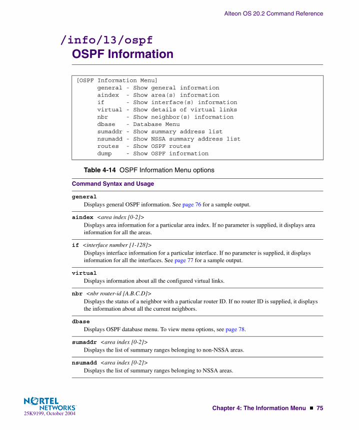
Alteon OS 20.2 Command Reference
Chapter 4: The Information Menu � 7525K9199, October 2004
/info/l3/ospfOSPF Information
[OSPF Information Menu] general - Show general information aindex - Show area(s) information if - Show interface(s) information virtual - Show details of virtual links nbr - Show neighbor(s) information dbase - Database Menu sumaddr - Show summary address list nsumadd - Show NSSA summary address list routes - Show OSPF routes dump - Show OSPF information
Table 4-14 OSPF Information Menu options
Command Syntax and Usage
general
Displays general OSPF information. See page 76 for a sample output.
aindex <area index [0-2]>Displays area information for a particular area index. If no parameter is supplied, it displays area information for all the areas.
if <interface number [1-128]>Displays interface information for a particular interface. If no parameter is supplied, it displays information for all the interfaces. See page 77 for a sample output.
virtual
Displays information about all the configured virtual links.
nbr <nbr router-id [A.B.C.D]>Displays the status of a neighbor with a particular router ID. If no router ID is supplied, it displays the information about all the current neighbors.
dbase
Displays OSPF database menu. To view menu options, see page 78.
sumaddr <area index [0-2]>Displays the list of summary ranges belonging to non-NSSA areas.
nsumadd <area index [0-2]>Displays the list of summary ranges belonging to NSSA areas.
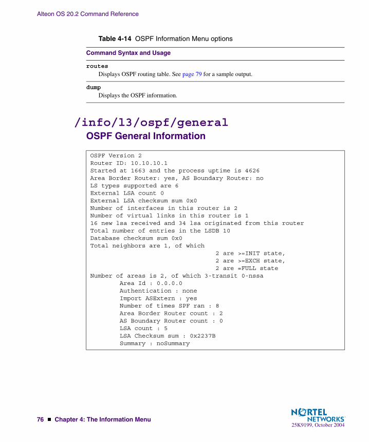
Alteon OS 20.2 Command Reference
76 � Chapter 4: The Information Menu25K9199, October 2004
/info/l3/ospf/generalOSPF General Information
routes
Displays OSPF routing table. See page 79 for a sample output.
dump
Displays the OSPF information.
OSPF Version 2Router ID: 10.10.10.1Started at 1663 and the process uptime is 4626Area Border Router: yes, AS Boundary Router: noLS types supported are 6External LSA count 0External LSA checksum sum 0x0Number of interfaces in this router is 2Number of virtual links in this router is 116 new lsa received and 34 lsa originated from this routerTotal number of entries in the LSDB 10Database checksum sum 0x0Total neighbors are 1, of which 2 are >=INIT state, 2 are >=EXCH state, 2 are =FULL stateNumber of areas is 2, of which 3-transit 0-nssa Area Id : 0.0.0.0 Authentication : none Import ASExtern : yes Number of times SPF ran : 8 Area Border Router count : 2 AS Boundary Router count : 0 LSA count : 5 LSA Checksum sum : 0x2237B Summary : noSummary
Table 4-14 OSPF Information Menu options
Command Syntax and Usage

Alteon OS 20.2 Command Reference
Chapter 4: The Information Menu � 7725K9199, October 2004
/info/l3/ospf/ifOSPF Interface Information
Ip Address 10.10.12.1, Area 0.0.0.1, Admin Status UP Router ID 10.10.10.1, State DR, Priority 1 Designated Router (ID) 10.10.10.1, Ip Address 10.10.12.1 Backup Designated Router (ID) 10.10.14.1, Ip Address 10.10.12.2 Timer intervals, Hello 10, Dead 40, Wait 1663, Retransmit 5, Poll interval 0, Transit delay 1 Neighbor count is 1 If Events 4, Authentication type none
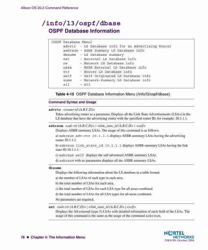
Alteon OS 20.2 Command Reference
78 � Chapter 4: The Information Menu25K9199, October 2004
/info/l3/ospf/dbaseOSPF Database Information
[OSPF Database Menu] advrtr - LS Database info for an Advertising Router asbrsum - ASBR Summary LS Database info dbsumm - LS Database summary ext - External LS Database info nw - Network LS Database info nssa - NSSA External LS Database info rtr - Router LS Database info self - Self Originated LS Database info summ - Network-Summary LS Database info all - All
Table 4-15 OSPF Database Information Menu (/info/l3/ospf/dbase)
Command Syntax and Usage
advrtr <router-id (A.B.C.D)>Takes advertising router as a parameter. Displays all the Link State Advertisements (LSAs) in the LS database that have the advertising router with the specified router ID, for example: 20.1.1.1.
asbrsum <adv-rtr (A.B.C.D)> | <link_state_id (A.B.C.D> | <self>Displays ASBR summary LSAs. The usage of this command is as follows:
a) asbrsum adv-rtr 20.1.1.1 displays ASBR summary LSAs having the advertising router 20.1.1.1.
b) asbrsum link_state_id 10.1.1.1 displays ASBR summary LSAs having the link state ID 10.1.1.1.
c) asbrsum self displays the self advertised ASBR summary LSAs.
d) asbrsum with no parameters displays all the ASBR summary LSAs.
dbsumm
Displays the following information about the LS database in a table format:
a) the number of LSAs of each type in each area.
b) the total number of LSAs for each area.
c) the total number of LSAs for each LSA type for all areas combined.
d) the total number of LSAs for all LSA types for all areas combined.
No parameters are required.
ext <adv-rtr (A.B.C.D)>|<link_state_id (A.B.C.D>|<self>Displays the AS-external (type 5) LSAs with detailed information of each field of the LSAs. The usage of this command is the same as the usage of the command asbrsum.
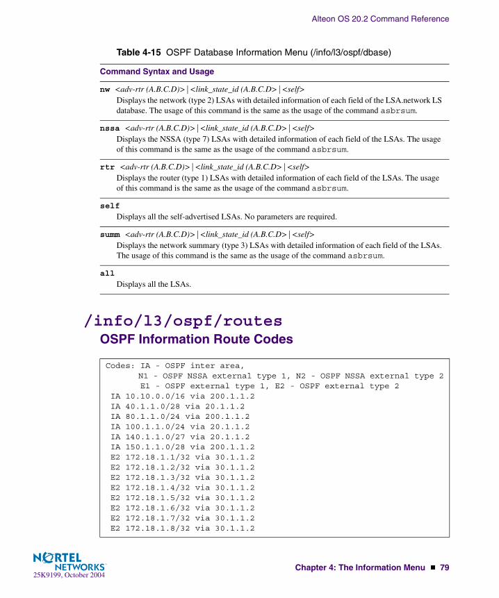
Alteon OS 20.2 Command Reference
Chapter 4: The Information Menu � 7925K9199, October 2004
/info/l3/ospf/routesOSPF Information Route Codes
nw <adv-rtr (A.B.C.D)>|<link_state_id (A.B.C.D>|<self>Displays the network (type 2) LSAs with detailed information of each field of the LSA.network LS database. The usage of this command is the same as the usage of the command asbrsum.
nssa <adv-rtr (A.B.C.D)>|<link_state_id (A.B.C.D>|<self>Displays the NSSA (type 7) LSAs with detailed information of each field of the LSAs. The usage of this command is the same as the usage of the command asbrsum.
rtr <adv-rtr (A.B.C.D)>|<link_state_id (A.B.C.D>|<self>Displays the router (type 1) LSAs with detailed information of each field of the LSAs. The usage of this command is the same as the usage of the command asbrsum.
self
Displays all the self-advertised LSAs. No parameters are required.
summ <adv-rtr (A.B.C.D)>|<link_state_id (A.B.C.D>|<self>Displays the network summary (type 3) LSAs with detailed information of each field of the LSAs. The usage of this command is the same as the usage of the command asbrsum.
all
Displays all the LSAs.
Codes: IA - OSPF inter area, N1 - OSPF NSSA external type 1, N2 - OSPF NSSA external type 2 E1 - OSPF external type 1, E2 - OSPF external type 2 IA 10.10.0.0/16 via 200.1.1.2 IA 40.1.1.0/28 via 20.1.1.2 IA 80.1.1.0/24 via 200.1.1.2 IA 100.1.1.0/24 via 20.1.1.2 IA 140.1.1.0/27 via 20.1.1.2 IA 150.1.1.0/28 via 200.1.1.2 E2 172.18.1.1/32 via 30.1.1.2 E2 172.18.1.2/32 via 30.1.1.2 E2 172.18.1.3/32 via 30.1.1.2 E2 172.18.1.4/32 via 30.1.1.2 E2 172.18.1.5/32 via 30.1.1.2 E2 172.18.1.6/32 via 30.1.1.2 E2 172.18.1.7/32 via 30.1.1.2 E2 172.18.1.8/32 via 30.1.1.2
Table 4-15 OSPF Database Information Menu (/info/l3/ospf/dbase)
Command Syntax and Usage

Alteon OS 20.2 Command Reference
80 � Chapter 4: The Information Menu25K9199, October 2004
/info/igmpIGMP Multicast Group Information
Table 4-16 describes the commands used to display information about IGMP groups learned by the switch.
/info/igmp/snoopIGMP Multicast Router Port Information
Table 4-17 describes the commands used to display information about IGMP groups learned by the switch.
[IGMP Menu] snoop - Show IGMP Snooping Multicast Group Information mrouter - Show IGMP Snooping Multicast Router Port information
Table 4-16 IGMP Multicast Group Menu Options (/info/igmp)
Command Syntax and Usage
snoop
Displays a single IGMP multicast group information.
mrouter
Displays static Multicast Router information.
[IGMP Snooping Menu] find - Show a single group by IP group address vlan - Show groups on a single vlan port - Show groups on a single port dump - Show all groups
Table 4-17 IGMP Multicast Group Menu Options (/info/igmp/snoop)
Command Syntax and Usage
find <IP address>Displays a single IGMP multicast group by its IP address.
vlan <VLAN number>Displays all IGMP multicast groups on a single VLAN.

Alteon OS 20.2 Command Reference
Chapter 4: The Information Menu � 8125K9199, October 2004
/info/igmp/mrouterIGMP Multicast Router Port Information
Table 4-18 describes the commands used to display information about multicast routers learned through IGMP Snooping.
port <Port number or alias>Displays all IGMP multicast groups on a single port.
dump
Displays information for all multicast groups.
[IGMP Multicast Router Ports Menu] vlan - Show all learned multicast router ports on a single vlan dump - Show all learned multicast router ports versions - Show last detected multicast router IGMP versions
Table 4-18 IGMP Multicast Router Menu Options (/info/igmp/mrouter)
Command Syntax and Usage
vlan
Displays information for all multicast groups learned on the selected VLAN.
dump
Displays information for all multicast groups learned by the switch.
versions
Displays the IGMP version of the most recent multicast group learned by the switch.
Table 4-17 IGMP Multicast Group Menu Options (/info/igmp/snoop)
Command Syntax and Usage
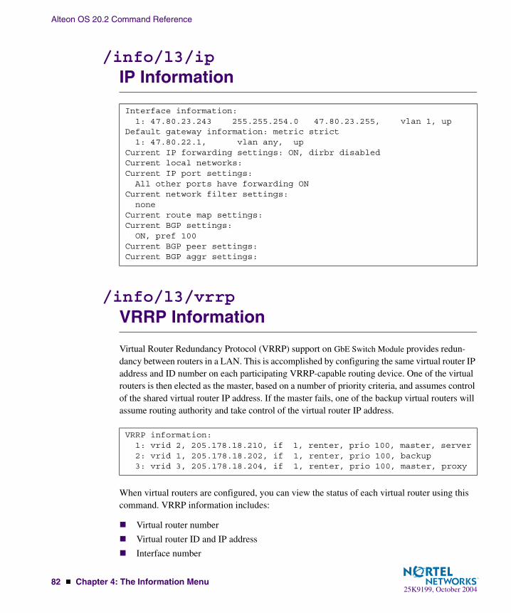
Alteon OS 20.2 Command Reference
82 � Chapter 4: The Information Menu25K9199, October 2004
/info/l3/ipIP Information
/info/l3/vrrpVRRP Information
Virtual Router Redundancy Protocol (VRRP) support on GbE Switch Module provides redun-dancy between routers in a LAN. This is accomplished by configuring the same virtual router IP address and ID number on each participating VRRP-capable routing device. One of the virtual routers is then elected as the master, based on a number of priority criteria, and assumes control of the shared virtual router IP address. If the master fails, one of the backup virtual routers will assume routing authority and take control of the virtual router IP address.
When virtual routers are configured, you can view the status of each virtual router using this command. VRRP information includes:
� Virtual router number
� Virtual router ID and IP address
� Interface number
Interface information: 1: 47.80.23.243 255.255.254.0 47.80.23.255, vlan 1, upDefault gateway information: metric strict 1: 47.80.22.1, vlan any, upCurrent IP forwarding settings: ON, dirbr disabledCurrent local networks:Current IP port settings: All other ports have forwarding ONCurrent network filter settings: noneCurrent route map settings:Current BGP settings: ON, pref 100Current BGP peer settings: Current BGP aggr settings:
VRRP information:1: vrid 2, 205.178.18.210, if 1, renter, prio 100, master, server2: vrid 1, 205.178.18.202, if 1, renter, prio 100, backup3: vrid 3, 205.178.18.204, if 1, renter, prio 100, master, proxy

Alteon OS 20.2 Command Reference
Chapter 4: The Information Menu � 8325K9199, October 2004
� Ownership status
� owner identifies the preferred master virtual router. A virtual router is the owner when the IP address of the virtual router and its IP interface are the same.
� renter identifies virtual routers which are not owned by this device.
� Priority value. During the election process, the virtual router with the highest priority becomes master.
� Activity status
� master identifies the elected master virtual router.
� backup identifies that the virtual router is in backup mode.
� init identifies that the virtual router is waiting for a startup event. Once it receives a startup event, it transitions to master if its priority is 255, (the IP address owner), or transitions to backup if it is not the IP address owner.
� Server status. The server state identifies virtual routers that support Layer 4 services. These are known as virtual server routers: any virtual router whose IP address is the same as any configured virtual server IP address.
� Proxy status. The proxy state identifies virtual proxy routers, where the virtual router shares the same IP address as a proxy IP address. The use of virtual proxy routers enables redundant switches to share the same IP address, minimizing the number of unique IP addresses that must be configured.

Alteon OS 20.2 Command Reference
84 � Chapter 4: The Information Menu25K9199, October 2004
/info/slbSLB Information
Layer 4 information includes the following:
[Server Load Balancing Information Menu] sess - Session Table Information Menu real - Show real server information virt - Show virtual server information filt - Show filter information port - Show port information idshash - Show IDS server selected by hash or minmisses metric bind - Show real server selected by hash or minmisses metric cookie - Decode the HEX value to get the VIP and RIP synatk - Show SYN attack detection information dump - Show all layer 4 information
Table 4-19 Layer 4 Information Menu Options (/info/slb)
Command Syntax and Usage
sess
Displays the Session Table Information Menu. To view menu options, see page 85.
real <real server number (1-63)>Displays Real server number, real IP address, MAC address, VLAN, physical switch port, layer where health check is performed, and health check result.
virt <virtual server number (1-64)>� Displays Virtual Server State: Virtual server number, IP address, virtual MAC address� Virtual Port State: Virtual service or port, server port mapping, real server group, group backup
server.
filt <filter ID (1-1024)>|list|allow|deny|redir|natDisplays the filter number, destination port, real server port, real server group, health check layer, group backup server, URL for health checks, and real server group, IP address, backup server, and status.
port <port alias or number>Displays the physical port number, proxy IP address, filter status, a list of applied filters, and client and/or server Layer 4 activity.
idshash <IP address 1> <IP address 2>Displays the Intrusion Detection System server selected by hash or minmisses metric.
bind <IP address> <mask> <group number>Displays the real server selected by hash or minmisses metric.

Alteon OS 20.2 Command Reference
Chapter 4: The Information Menu � 8525K9199, October 2004
/info/slb/sessSession Table Information
cookie <16 bytes cookie value in hexadecimal format as 0XXXXXXXXXXXXXXXXX>Decodes the hexadecimal value to get the virtual server IP address and real server IP address.
synatk
Displays SYN attack detection information. To identify whether or not the server is under SYN attack, the number of new half open sessions is examined within a set period of time, for example, every two seconds. This feature requires dbind to be enabled.
dump
Displays all Layer 4 information for the switch. For details, see page 90.
[Session Table Information Menu] cip - Show all session entries with source IP address cport - Show all session entries with source port dip - Show all session entries with destination IP address dport - Show all session entries with destination port pip - Show all session entries with proxy IP address pport - Show all session entries with proxy port filter - Show all session entries with matching filter flag - Show all session entries with matching flag port - Show all session entries with ingress port real - Show all session entries with real IP address sp - Show all session entries on sp dump - Show all session entries help - Session entry description
Table 4-20 Session Information Menu Options (/info/slb/sess)
Command Syntax and Usage
cip <IP address>Displays all session entries with client’s source IP address.
cport <real port>Displays all session entries with source (client) port.
dip <IP address>Displays all session entries with destination IP address.
Table 4-19 Layer 4 Information Menu Options (/info/slb)
Command Syntax and Usage
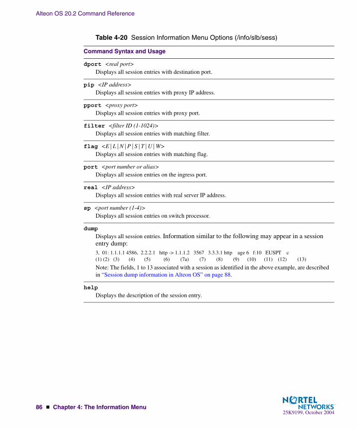
Alteon OS 20.2 Command Reference
86 � Chapter 4: The Information Menu25K9199, October 2004
dport <real port>Displays all session entries with destination port.
pip <IP address>Displays all session entries with proxy IP address.
pport <proxy port>Displays all session entries with proxy port.
filter <filter ID (1-1024)>Displays all session entries with matching filter.
flag <E|L|N|P|S|T|U|W>Displays all session entries with matching flag.
port <port number or alias>Displays all session entries on the ingress port.
real <IP address>Displays all session entries with real server IP address.
sp <port number (1-4)>Displays all session entries on switch processor.
dump
Displays all session entries. Information similar to the following may appear in a session entry dump:3, 01: 1.1.1.1 4586, 2.2.2.1 http -> 1.1.1.2 3567 3.3.3.1 http age 6 f:10 EUSPT c(1) (2) (3) (4) (5) (6) (7a) (7) (8) (9) (10) (11) (12) (13)
Note: The fields, 1 to 13 associated with a session as identified in the above example, are described in “Session dump information in Alteon OS” on page 88.
help
Displays the description of the session entry.
Table 4-20 Session Information Menu Options (/info/slb/sess)
Command Syntax and Usage

Alteon OS 20.2 Command Reference
Chapter 4: The Information Menu � 8725K9199, October 2004
Samples of Session Dumps for Different Applications
L4 HTTP
3,01: 172.21.12.19 1040, 39.2.2.1 http -> 47.81.24.79 http age 4
L4-L7 WCR HTTP
2,16: 172.21.8.200 44687, 172.21.8.51 http -> 192.168.1.11 wcr age 4 f:12 E 3,01: 172.21.12.19 1040, 39.2.2.1 http -> 47.81.24.79 urlwcr age 6 f:123 E
RTSP
L4-L7 RTSP
3,01: 172.21.12.19 4586, 39.2.2.1 rtsp -> 47.81.144.13 rtsp age 10 EU 3,01: 172.21.12.19 6970, 39.2.2.1 21220 -> 47.81.144.13 21220 age 10 P The first session is RTSP TCP control connection. The second session is RTSP UDP data connection.
3,01: 172.21.12.19 6970, 39.2.2.1 rtsp -> 47.81.144.13 0 age 10 P During client-server port negotiation, the destination port shows “rtsp” and server port shows “0”
L7 WCR RTSP
3,01: 172.21.12.19 4586, 39.2.2.1 rtsp -> 47.81.144.13 urlwcr age 10 f:100 EU 3,01: 172.21.12.19 6970, 39.2.2.1 21220 -> 47.81.144.13 21220 age 10 P
Filtering LinkLB
2,07: 10.0.1.26 1706, 205.178.14.84 http -> 192.168.4.10 linklb age 8 f:10 E
FTP
1,00: 172.31.4.215 80, 172.31.4.200 0 172.31.3.11 age 8 EP c:1 1,09: 172.31.4.215 4098, 172.31.4.200 ftp ->172.31.3.20 ftp age 10 EU 1,09: 172.31.4.215 4102, 172.31.4.200 ftp-data ->172.31.3.20 ftp-data age 10 E
NAT
2,05: 172.21.8.16 2559, 10.0.1.26 http NAT age 2 f:24 E
Persistent session
3,00: 237.162.52.123 160.10.20.30 age 4 EPS C:3 The destination port, real server IP and server port are not shown for persistent session.

Alteon OS 20.2 Command Reference
88 � Chapter 4: The Information Menu25K9199, October 2004
Session dump information in Alteon OS
Field Description
(1) SP number This field indicates the Switch Port number that created the ses-sion.
(2) Ingress port This field shows the physical port through which the client traffic enters the switch.
(3) Source IP address
This field contains the source IP address from the client’s IP packet.
(4) Source port This field identifies the source port from the client’s TCP/UDP packet.
(5) Destination IP address
This field identifies the destination IP address from the client’s TCP/UDP packet.
(6) Destination port
This field identifies the destination port from client’s TCP/UDP packet.
(7a) Proxy IP address
This field contains the Proxy IP address substituted by the switch. This field contains the real server IP address of the corresponding server that the switch selects to forward the client packet to, for load balancing. If the switch does not find a live server, this field contains the same as the destination IP address mentioned in field (5).
This field also shows the real server IP address for filtering. No address is shown if the filter action is Allow, Deny or NAT. It will show “ALLOW”, “DENY” or “NAT” instead.
(7) Proxy Port This field identifies the TCP/UDP source port substituted by the switch.
(8) Real Server IP Address
For load balancing, this field contains the IP address of the real server that the switch selects to forward client packet to. If the switch does not find live server, this field is the same as destination IP address(5).For example: 3,01: 1.1.1.1 1040, 2.2.2.1 http -> 3.3.3.1 http age 10 3,01: 1.1.1.1 6970, 2.2.2.1 rtsp -> 2.2.2.1 21220 age 10 PFor filtering, this field also shows the real server IP address. No address is shown if the filter action is Allow, Deny or NAT. It will show ALLOW, DENY or NAT instead.For example: 3,01: 1.1.1.1 1040, 2.2.2.1 http -> 3.3.3.1 http age 10 f:11 2,07: 1.1.1.1 1706, 2.2.2.1 http-> 192.168.4.10 linklb age 8 f:10 E

Alteon OS 20.2 Command Reference
Chapter 4: The Information Menu � 8925K9199, October 2004
(9) Server port This field is the same as the destination port (field 6) for load bal-ancing except for the RTSP UDP session. For RTSP UDP session, this server port is obtained from the client-server negotiation.
This field is the filtering application port for filtering. It is for internal use only. This field can be “urlwcr”, “wcr”, “idslb”, “link-slb” or “nonat”.
(10) Age This is the session timeout value. If no packet is received within the value specified, the session is freed.
(11) Filter number This field indicates the session created by filtering code as a result of the IP header keys matching the filtering criteria.
(12) Flag “E”: Indicates the session is in use and will be aged out if no traffic is received within session timeout value. “P”: Indicates the session is a persistent session and is not to be aged out. Fields (6), (7) and (8) cannot not have persistent session. “U”: Indicates the session is L7 delayed binding and the switch is trying to open TCP connection to the real server. “S”: Indicates the session is persistent session and the application is special SSL or Cookie Pbind. “T”: Indicates the session is TCP rate limiting per-client entry.
(13) Persistent session user count
This counter indicates the number of client sessions created to associate with this persistent session.
Field Description

Alteon OS 20.2 Command Reference
90 � Chapter 4: The Information Menu25K9199, October 2004
/info/slb/dumpShow All Layer 4 Information
Real server state: 1: 210.1.2.200, 00:01:02:c1:4b:48, vlan 1, port 1, health 3, up 2: 210.1.2.1, 00:01:02:70:4d:4a, vlan 1, port 8, health 3, up 26: 20.20.20.102, 00:03:47:07:a4:9e, vlan 1, port 6, health 3, up 27: 20.20.20.101, 00:01:02:71:9c:a6, vlan 1, port 7, health 3, up
Virtual server state: 1: 20.20.20.200, 00:60:cf:47:5c:1e virtual ports: http: rport http, group 88, backup none, dbind HTTP Application: urlslb real servers: 26: 20.20.20.102, backup none, 2 ms, up exclusionary string matching: disabled 1: any 2: urlone 27: 20.20.20.101, backup none, 1 ms, up exclusionary string matching: disabled 3: urltwo 4: urlthree
Redirect filter state:Action redirdport http, rport 3128, vlan any200: group 1, health 3, backup none proxy enabled, radius snoop disabled real servers: 1: 210.1.2.200, backup none, 3 ms, up 2: 210.1.2.1, backup none, 2 ms, up
Port state: 1: filt disabled, filters: 80 2: idslb filt enabled, filters: 200 3: idslb filt enabled, filters: 200 4: filt disabled, filters: 50 200

Alteon OS 20.2 Command Reference
Chapter 4: The Information Menu � 9125K9199, October 2004
/info/linkLink Status Information
NOTE – The sample screens that appear in this document might differ slightly from the screens displayed by your system. Screen content varies based on the type of BladeCenter unit that you are using and the firmware versions and options that are installed.
Use this command to display link status information about each port on an GbE Switch Module slot, including:
� Port alias
� Port speed (10, 100, 10/100, or 1000)
� Duplex mode (half, full, any, or auto)
� Flow control for transmit and receive (no, yes, or auto)
� Link status (up or down)
Alias Port Speed Duplex Flow Ctrl Link---- ----- ----- -------- --TX-----RX-- ------ INT1 1 1000 full yes yes up INT2 2 1000 full yes yes up INT3 3 1000 full yes yes up INT4 4 1000 full yes yes up INT5 5 1000 full yes yes down INT6 6 1000 full yes yes up INT7 7 1000 full yes yes up INT8 8 1000 full yes yes up INT9 9 1000 full yes yes up INT10 10 1000 full yes yes up INT11 11 1000 full yes yes up INT12 12 1000 full yes yes up INT13 13 1000 full yes yes up INT14 14 1000 full yes yes up MGT1 15 100 full yes yes up MGT2 16 100 full yes yes down EXT1 17 any any yes yes up EXT2 18 any any yes yes up EXT3 19 any any yes yes up EXT4 20 any any yes yes up

Alteon OS 20.2 Command Reference
92 � Chapter 4: The Information Menu25K9199, October 2004
/info/portPort Information
NOTE – The sample screens that appear in this document might differ slightly from the screens displayed by your system. Screen content varies based on the type of BladeCenter unit that you are using and the firmware versions and options that are installed.
Port information includes:
� Port alias
� Whether the port uses VLAN tagging or not (y or n)
� Port VLAN ID (PVID)
� Port name
� VLAN membership
� Whether RMON is enabled or disabled on the port
Alias Port Tag FAST RMON PVID NAME VLAN(s)----- ---- --- ---- ---- ---- -------------- -----------------INT1 1 y n d 1 INT1 1 4095INT2 2 y n d 1 INT2 1 4095INT3 3 y n d 1 INT3 1 4095INT4 4 y n d 1 INT4 1 4095INT5 5 y n d 1 INT5 1 4095INT6 6 y n d 1 INT6 1 4095INT7 7 y n d 1 INT7 1 4095INT8 8 y n d 1 INT8 1 4095INT9 9 y n d 1 INT9 1 4095INT10 10 y n d 1 INT10 1 4095INT11 11 y n d 1 INT11 1 4095INT12 12 y n d 1 INT12 1 4095INT13 13 y n d 1 INT13 1 4095INT14 14 y n d 1 INT14 1 4095MGT1 15 y n d 4095 MGT1 4095MGT2 16 y n d 4095 MGT2 4095EXT1 17 n n d 1 EXT1 1EXT2 18 n n d 1 EXT2 1EXT3 19 n n d 1 EXT3 1EXT4 20 n n d 1 EXT4 1
Alteon OS 20.2 Command Reference
Chapter 4: The Information Menu � 9325K9199, October 2004
/info/dumpInformation Dump
Use the dump command to dump all switch information available from the Information Menu (10K or more, depending on your configuration). This data is useful for tuning and debugging switch performance.
If you want to capture dump data to a file, set your communication software on your worksta-tion to capture session data prior to issuing the dump commands.

Alteon OS 20.2 Command Reference
94 � Chapter 4: The Information Menu25K9199, October 2004

25K9199, October 200495
CHAPTER 5The Statistics Menu
You can view switch performance statistics in both the user and administrator command modes. This chapter discusses how to use the command line interface to display switch statistics.
/statsStatistics Menu
[Statistics Menu] port - Port Stats Menu l2 - Layer 2 Stats Menu l3 - Layer 3 Stats Menu slb - Server Load Balancing (L4-7) Stats Menu mp - MP-specific Stats Menu sp - SP-specific Stats Menu pace - Packet Acceleration Stats Menu snmp - Show SNMP stats ntp - Show NTP stats dump - Dump all stats
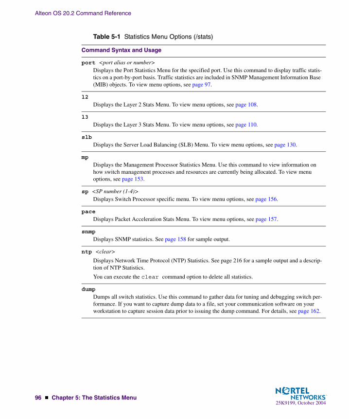
Alteon OS 20.2 Command Reference
96 � Chapter 5: The Statistics Menu25K9199, October 2004
Table 5-1 Statistics Menu Options (/stats)
Command Syntax and Usage
port <port alias or number>Displays the Port Statistics Menu for the specified port. Use this command to display traffic statis-tics on a port-by-port basis. Traffic statistics are included in SNMP Management Information Base (MIB) objects. To view menu options, see page 97.
l2
Displays the Layer 2 Stats Menu. To view menu options, see page 108.
l3
Displays the Layer 3 Stats Menu. To view menu options, see page 110.
slb
Displays the Server Load Balancing (SLB) Menu. To view menu options, see page 130.
mp
Displays the Management Processor Statistics Menu. Use this command to view information on how switch management processes and resources are currently being allocated. To view menu options, see page 153.
sp <SP number (1-4)>Displays Switch Processor specific menu. To view menu options, see page 156.
pace
Displays Packet Acceleration Stats Menu. To view menu options, see page 157.
snmp
Displays SNMP statistics. See page 158 for sample output.
ntp <clear>
Displays Network Time Protocol (NTP) Statistics. See page 216 for a sample output and a descrip-tion of NTP Statistics.
You can execute the clear command option to delete all statistics.
dump
Dumps all switch statistics. Use this command to gather data for tuning and debugging switch per-formance. If you want to capture dump data to a file, set your communication software on your workstation to capture session data prior to issuing the dump command. For details, see page 162.

Alteon OS 20.2 Command Reference
Chapter 5: The Statistics Menu � 9725K9199, October 2004
/stats/port <port alias or number>Port Statistics Menu
This menu displays traffic statistics on a port-by-port basis. Traffic statistics include SNMP Management Information Base (MIB) objects.
[Port Statistics Menu] brg - Show bridging ("dot1") stats ether - Show Ethernet ("dot3") stats if - Show interface ("if") stats ip - Show Internet Protocol ("IP") stats link - Show link stats rmon - Show RMON stats dump - Dump port stats clear - Clear all port stats
Table 5-2 Port Statistics Menu Options (/stats/port)
Command Syntax and Usage
brg
Displays bridging (“dot1”) statistics for the port. See page 98 for sample output.
ether
Displays Ethernet (“dot1”) statistics for the port. See page 99 for sample output.
if
Displays interface statistics for the port. See page 102 for sample output.
ip
Displays IP statistics for the port. See page 104 for sample output.
link
Displays link statistics for the port. See page 105 for sample output.
rmon
Displays RMON statistics for the port. See page 105 for sample output.
dump
Displays all the port statistics.
clear
This command clears all the statistics on the port.

Alteon OS 20.2 Command Reference
98 � Chapter 5: The Statistics Menu25K9199, October 2004
/stats/port <port alias or number>/brgBridging StatisticsThis menu option enables you to display the bridging statistics of the selected port.
Bridging statistics for port INT1:dot1PortInFrames: 63242584dot1PortOutFrames: 63277826dot1PortInDiscards: 0dot1TpLearnedEntryDiscards: 0dot1BasePortDelayExceededDiscards: NAdot1BasePortMtuExceededDiscards: NAdot1StpPortForwardTransitions: 0
Table 5-3 Bridging Statistics of a Port (/stats/port/brg)
Statistics Description
dot1PortInFrames The number of frames that have been received by this port from its seg-ment. A frame received on the interface corresponding to this port is only counted by this object if and only if it is for a protocol being processed by the local bridging function, including bridge management frames.
dot1PortOutFrames The number of frames that have been transmitted by this port to its seg-ment. Note that a frame transmitted on the interface corresponding to this port is only counted by this object if and only if it is for a protocol being processed by the local bridging function, including bridge management frames.
dot1PortInDiscards Count of valid frames received which were discarded (that is, filtered) by the Forwarding Process.
dot1TpLearnedEntry Discards
The total number of Forwarding Database entries, which have been or would have been learnt, but have been discarded due to a lack of space to store them in the Forwarding Database. If this counter is increasing, it indicates that the Forwarding Database is regularly becoming full (a con-dition which has unpleasant performance effects on the subnetwork). If this counter has a significant value but is not presently increasing, it indi-cates that the problem has been occurring but is not persistent.
dot1BasePortDelay ExceededDiscards
The number of frames discarded by this port due to excessive transit delay through the bridge. It is incriminated by both transparent and source route bridges.
dot1BasePortMtuExceededDiscards
The number of frames discarded by this port due to an excessive size. It is incremented by both transparent and source route bridges.
dot1StpPortForward Transitions
The number of times this port has transitioned from the Learning state to the Forwarding state.

Alteon OS 20.2 Command Reference
Chapter 5: The Statistics Menu � 9925K9199, October 2004
/stats/port <port alias or number>/etherEthernet StatisticsThis menu option enables you to display the ethernet statistics of the selected port
Ethernet statistics for port INT1:dot3StatsAlignmentErrors: 0dot3StatsFCSErrors: 0dot3StatsSingleCollisionFrames: 0dot3StatsMultipleCollisionFrames: 0dot3StatsSQETestErrors: NAdot3StatsDeferredTransmissions: 0dot3StatsLateCollisions: 0dot3StatsExcessiveCollisions: 0dot3StatsInternalMacTransmitErrors: NAdot3StatsCarrierSenseErrors: 0dot3StatsFrameTooLongs: 0dot3StatsInternalMacReceiveErrors: 0dot3CollFrequencies [1-15]: NA
Table 5-4 Ethernet Statistics for Port (/stats/port/ether)
Statistics Description
dot3StatsAlignmentErrors
A count of frames received on a particular interface that are not an inte-gral number of octets in length and do not pass the Frame Check Sequence (FCS) check.The count represented by an instance of this object is incremented when the alignmentError status is returned by the MAC service to the Logical Link Control (LLC) (or other MAC user). Received frames for which multiple error conditions obtained are, according to the conven-tions of IEEE 802.3 Layer Management, counted exclusively according to the error status presented to the LLC.
dot3StatsFCSErrors A count of frames received on a particular interface that are an integral number of octets in length but do not pass the Frame Check Sequence (FCS) check.The count represented by an instance of this object is incremented when the frameCheckError status is returned by the MAC service to the LLC (or other MAC user). Received frames for which multiple error con-ditions obtained are, according to the conventions of IEEE 802.3 Layer Management, counted exclusively according to the error status presented to the LLC.

Alteon OS 20.2 Command Reference
100 � Chapter 5: The Statistics Menu25K9199, October 2004
dot3StatsSingle-CollisionFrames
A count of successfully transmitted frames on a particular interface for which transmission is inhibited by exactly one collision.A frame that is counted by an instance of this object is also counted by the corresponding instance of either the ifOutUcastPkts, ifOutMul-ticastPkts, or ifOutBroadcastPkts, and is not counted by the corresponding instance of the dot3StatsMultipleCollision-Frame object.
dot3StatsMultiple-CollisionFrames
A count of successfully transmitted frames on a particular interface for which transmission is inhibited by more than one collision.A frame that is counted by an instance of this object is also counted by the corresponding instance of either the ifOutUcastPkts, ifOutMul-ticastPkts, or ifOutBroadcastPkts, and is not counted by the corresponding instance of the dot3StatsSingleCollision-Frames object.
dot3StatsSQETest-Errors
A count of times that the SQE TEST ERROR message is generated by the PLS sub layer for a particular interface. The SQE TEST ERROR message is defined in section 7.2.2.2.4 of ANSI/IEEE 802.3-1985 and its genera-tion is described in section 7.2.4.6 of the same document.
dot3StatsDeferred-Transmissions
A count of frames for which the first transmission attempt on a particular interface is delayed because the medium is busy.The count represented by an instance of this object does not include frames involved in collisions.
dot3StatsLate-Collisions
The number of times that a collision is detected on a particular interface later than 512 bit-times into the transmission of a packet.Five hundred and twelve bit-times corresponds to 51.2 microseconds on a 10 Mbit/s system. A (late) collision included in a count represented by an instance of this object is also considered as a (generic) collision for pur-poses of other collision-related statistics.
dot3StatsExcessiveCollisions
A count of frames for which transmission on a particular interface fails due to excessive collisions.
dot3StatsInternal-MacTransmitErrors
A count of frames for which transmission on a particular interface fails due to an internal MAC sub layer transmit error. A frame is only counted by an instance of this object if it is not counted by the corresponding instance of either the dot3StatsLateCollisions object, the dot3StatsExcessiveCollisions object, or the dot3Stats-CarrierSenseErrors object.The precise meaning of the count represented by an instance of this object is implementation-specific. In particular, an instance of this object may represent a count of transmission errors on a particular interface that are not otherwise counted.
Table 5-4 Ethernet Statistics for Port (/stats/port/ether)
Statistics Description

Alteon OS 20.2 Command Reference
Chapter 5: The Statistics Menu � 10125K9199, October 2004
dot3StatsCarrier-SenseErrors
The number of times that the carrier sense condition was lost or never asserted when attempting to transmit a frame on a particular interface.The count represented by an instance of this object is incremented at most once per transmission attempt, even if the carrier sense condition fluctu-ates during a transmission attempt.
dot3StatsFrameToo-Longs
A count of frames received on a particular interface that exceed the maxi-mum permitted frame size.The count represented by an instance of this object is incremented when the frameTooLong status is returned by the MAC service to the LLC (or other MAC user). Received frames for which multiple error condi-tions obtained are, according to the conventions of IEEE 802.3 Layer Management, counted exclusively according to the error status presented to the LLC.
dot3StatsInternal-MacReceiveErrors
A count of frames for which reception on a particular interface fails due to an internal MAC sub layer receive error. A frame is only counted by an instance of this object if it is not counted by the corresponding instance of either the dot3StatsFrameTooLongs object, the dot3Stats-AlignmentErrors object, or the dot3StatsFCSErrors object.The precise meaning of the count represented by an instance of this object is implementation-specific. In particular, an instance of this object may represent a count of received errors on a particular interface that are not otherwise counted.
dot3Coll-Frequencies
A count of individual MAC frames for which the transmission (successful or otherwise) on a particular interface occurs after the frame has experienced exactly the number of collisions in the associated dot3CollCount object. For example, a frame which is transmitted on interface 77 after experiencing exactly 4 collisions would be indicated by incrementing only dot3CollFrequencies. 77.4. No other instance of dot3CollFrequencies would be incremented in this example.
Table 5-4 Ethernet Statistics for Port (/stats/port/ether)
Statistics Description

Alteon OS 20.2 Command Reference
102 � Chapter 5: The Statistics Menu25K9199, October 2004
/stats/port <port alias or number>/ifInterface StatisticsThis menu option enables you to display the interface statistics of the selected port.
Interface statistics for port EXT1: ifHCIn Counters ifHCOut CountersOctets: 51697080313 51721056808UcastPkts: 65356399 65385714BroadcastPkts: 0 6516MulticastPkts: 0 0Discards: 0 0Errors: 0 21187
Table 5-5 Interface Statistics for Port (/stats/port/if)
Statistics Description
ifInOctets The total number of octets received on the interface, including framing characters.
ifInUcastPkts The number of packets, delivered by this sub-layer to a higher sub- layer, which were not addressed to a multicast or broadcast address at this sub-layer.
ifInBroadcastPkts The number of packets, delivered by this sub-layer to a higher sub- layer, which were addressed to a broadcast address at this sub-layer.
ifInMulticastPkts The total number of packets that higher-level protocols requested to be transmitted, and which were addressed to a multicast address at this sub-layer, including those that were discarded or not sent. For a MAC layer protocol, this includes both Group and Functional addresses.
ifInDiscards The number of inbound packets which were chosen to be discarded even though no errors had been detected to prevent their being delivered to a higher-layer protocol. One possible reason for discarding such a packet could be to free up buffer space.
ifInErrors For packet-oriented interfaces, the number of inbound packets that con-tained errors preventing them from being delivered to a higher-layer pro-tocol. For character-oriented or fixed-length interfaces, the number of inbound transmission units that contained errors preventing them from being deliverable to a higher-layer protocol.

Alteon OS 20.2 Command Reference
Chapter 5: The Statistics Menu � 10325K9199, October 2004
ifInUnknownProtos For packet-oriented interfaces, the number of packets received via the interface which were discarded because of an unknown or unsupported protocol. For character-oriented or fixed-length interfaces which support protocol multiplexing, the number of transmission units received via the interface which were discarded because of an unknown or unsupported protocol. For any interface which does not support protocol multiplexing, this counter will always be 0.
ifOutOctets The total number of octets transmitted out of the interface, including framing characters.
ifOutUcastPkts The total number of packets that higher-level protocols requested to be transmitted, and which were not addressed to a multicast or broadcast address at this sub-layer, including those that were discarded or not sent.
ifOutBroadcastPkts The total number of packets that higher-level protocols requested to be transmitted, and which were addressed to a broadcast address at this sub-layer, including those that were discarded or not sent. This object is a 64-bit version of ifOutBroadcastPkts.
ifOutMulticastPkts The total number of packets that higher-level protocols requested to be transmitted, and which were addressed to a multicast address at this sub-layer, including those that were discarded or not sent. For a MAC layer protocol, this includes both Group and Functional addresses. This object is a 64-bit version of ifOutMulticastPkts.
ifOutDiscards The number of outbound packets which were chosen to be discarded even though no errors had been detected to prevent their being transmitted. One possible reason for discarding such a packet could be to free up buffer space.
ifOutErrors For packet-oriented interfaces, the number of outbound packets that could not be transmitted because of errors. For character-oriented or fixed-length interfaces, the number of outbound transmission units that could not be transmitted because of errors.
Table 5-5 Interface Statistics for Port (/stats/port/if)
Statistics Description

Alteon OS 20.2 Command Reference
104 � Chapter 5: The Statistics Menu25K9199, October 2004
/stats/port <port alias or number>/ipInterface Protocol StatisticsThis menu option enables you to display the interface statistics of the selected port.
IP statistics for port INT1:ipInReceives: 0ipInAddrErrors: 0 ipForwDatagrams: 0ipInUnknownProtos: 0 ipInDiscards: 0ipInDelivers: 0ipTtlExceeds: 0ipLANDattacks: 0
Table 5-6 Interface Protocol Statistics (/stats/port/ip)
Statistics Description
ipInReceives The total number of input datagrams received from interfaces, including those received in error.
ipInAddrErrors The number of input datagrams discarded because the IP address in their IP header’s destination field was not a valid address to be received at this entity (the switch). This count includes invalid addresses (for example, 0.0.0.0) and addresses of unsupported Classes (for example, Class E). For entities which are not IP Gateways and therefore do not forward data-grams, this counter includes datagrams discarded because the destination address was not a local address.
ipForwDatagrams The number of input datagrams for which this entity (the switch) was not their final IP destination, as a result of which an attempt was made to find a route to forward them to that final destination. In entities which do not act as IP Gateways, this counter will include only those packets which were Source-Routed via this entity (the switch), and the Source- Route option processing was successful.
ipInUnknownProtos The number of locally-addressed datagrams received successfully but discarded because of an unknown or unsupported protocol.
ipInDiscards The number of input IP datagrams for which no problems were encoun-tered to prevent their continued processing, but which were discarded (for example, for lack of buffer space). Note that this counter does not include any datagrams discarded while awaiting re-assembly.
ipInDelivers The total number of input datagrams successfully delivered to IP user-protocols (including ICMP).
ipTtlExceeds The number of IP datagram for which an ICMP TTL exceeded mes-sage was sent.

Alteon OS 20.2 Command Reference
Chapter 5: The Statistics Menu � 10525K9199, October 2004
/stats/port <port alias or number>/linkLink StatisticsThis menu enables you to display the link statistics of the selected port.
/stats/port <port alias or number>/rmonRMON StatisticsThis menu option enables you to display the remote monitor statistics of the selected port.
Link statistics for port INT1:linkStateChange: 1
Table 5-7 Link Statistics (/stats/port/link)
Statistics Description
linkStateChange The total number of link state changes.
RMON statistics for port EXT1:etherStatsDropEvents: 0etherStatsOctets: 3727038769etherStatsPkts: 69869242etherStatsBroadcastPkts: 0etherStatsMulticastPkts: 0etherStatsCRCAlignErrors: 0etherStatsUndersizePkts: 0etherStatsOversizePkts: 0etherStatsFragments: 0etherStatsJabbers: 0etherStatsCollisions: 0etherStatsPkts64Octets: 102426etherStatsPkts65to127Octets: 6050515etherStatsPkts128to255Octets: 12293234etherStatsPkts256to511Octets: 24586063etherStatsPkts64Octets: 49171870etherStatsPkts1024to1518Octets: 47539775
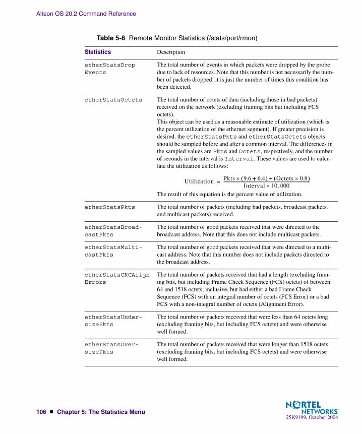
Alteon OS 20.2 Command Reference
106 � Chapter 5: The Statistics Menu25K9199, October 2004
Table 5-8 Remote Monitor Statistics (/stats/port/rmon)
Statistics Description
etherStatsDropEvents
The total number of events in which packets were dropped by the probe due to lack of resources. Note that this number is not necessarily the num-ber of packets dropped; it is just the number of times this condition has been detected.
etherStatsOctets The total number of octets of data (including those in bad packets) received on the network (excluding framing bits but including FCS octets).This object can be used as a reasonable estimate of utilization (which is the percent utilization of the ethernet segment). If greater precision is desired, the etherStatsPkts and etherStatsOctets objects should be sampled before and after a common interval. The differences in the sampled values are Pkts and Octets, respectively, and the number of seconds in the interval is Interval. These values are used to calcu-late the utilization as follows:
The result of this equation is the percent value of utilization.
etherStatsPkts The total number of packets (including bad packets, broadcast packets, and multicast packets) received.
etherStatsBroad-castPkts
The total number of good packets received that were directed to the broadcast address. Note that this does not include multicast packets.
etherStatsMulti-castPkts
The total number of good packets received that were directed to a multi-cast address. Note that this number does not include packets directed to the broadcast address.
etherStatsCRCAlign Errors
The total number of packets received that had a length (excluding fram-ing bits, but including Frame Check Sequence (FCS) octets) of between 64 and 1518 octets, inclusive, but had either a bad Frame Check Sequence (FCS) with an integral number of octets (FCS Error) or a bad FCS with a non-integral number of octets (Alignment Error).
etherStatsUnder-sizePkts
The total number of packets received that were less than 64 octets long (excluding framing bits, but including FCS octets) and were otherwise well formed.
etherStatsOver-sizePkts
The total number of packets received that were longer than 1518 octets (excluding framing bits, but including FCS octets) and were otherwise well formed.
Utilization Pkts 9.6 6.4�� �� Octets 0.8�� ��
Interval 10 000��--------------------------------------------------------------------------------------�

Alteon OS 20.2 Command Reference
Chapter 5: The Statistics Menu � 10725K9199, October 2004
etherStatsFrag-ments
The total number of packets received that were less than 64 octets in length (excluding framing bits but including FCS octets) and had either a bad Frame Check Sequence (FCS) with an integral number of octets (FCS Error) or a bad FCS with a non-integral number of octets (Align-ment Error).Note that it is entirely normal for etherStatsFragments to incre-ment. This is because it counts both runts (which are normal occurrences due to collisions) and noise hits. (A runt is a packet that is less than 64 bytes.)
etherStatsJabbers The total number of packets received that were longer than 1518 octets (excluding framing bits, but including FCS octets), and had either a bad Frame Check Sequence (FCS) with an integral number of octets (FCS Error) or a bad FCS with a non-integral number of octets (Alignment Error).Note that this definition of jabber is different than the definition in IEEE-802.3 section 8.2.1.5 (10Base-5) and section 10.3.1.4 (10Base-2). These documents define jabber as the condition where any packet exceeds 20 ms. The allowed range to detect jabber is between 20 milliseconds and 150 milliseconds.
etherStats-Collisions
The best estimate of the total number of collisions on this Ethernet seg-ment.The value returned will depend on the location of the RMON probe. Sec-tion 8.2.1.3 (10Base-5) and section 10.3.1.3 (10Base-2) of IEEE standard 802.3 states that a station must detect a collision, in the receive mode, if three or more stations are transmitting simultaneously. A repeater port must detect a collision when two or more stations are transmitting simul-taneously. Thus a probe placed on a repeater port could record more colli-sions than a probe connected to a station on the same segment would.Probe location plays a much smaller role when considering 10Base-T. 14.2.1.4 (10Base-T) of IEEE standard 802.3 defines a collision as the simultaneous presence of signals on the DO and RD circuits (transmitting and receiving at the same time). A 10Base-T station can only detect colli-sions when it is transmitting. Thus probes placed on a station and a repeater, should report the same number of collisions.Note also that an RMON probe inside a repeater should ideally report col-lisions between the repeater and one or more other hosts (transmit colli-sions as defined by IEEE 802.3k) plus receiver collisions observed on any coax segments to which the repeater is connected.
etherStatsPkts64-Octets
The total number of packets (including bad packets) received that were 64 octets in length (excluding framing bits but including Frame Check Sequence (FCS) octets).
Table 5-8 Remote Monitor Statistics (/stats/port/rmon)
Statistics Description
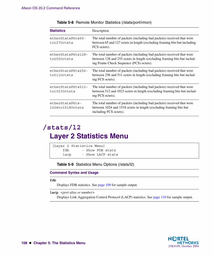
Alteon OS 20.2 Command Reference
108 � Chapter 5: The Statistics Menu25K9199, October 2004
/stats/l2Layer 2 Statistics Menu
etherStatsPkts65-to127Octets
The total number of packets (including bad packets) received that were between 65 and 127 octets in length (excluding framing bits but including FCS octets).
etherStatsPkts128-to255Octets
The total number of packets (including bad packets) received that were between 128 and 255 octets in length (excluding framing bits but includ-ing Frame Check Sequence (FCS) octets).
etherStatsPkts256-to511Octets
The total number of packets (including bad packets) received that were between 256 and 511 octets in length (excluding framing bits but includ-ing FCS octets).
etherStatsPkts512-to1023Octets
The total number of packets (including bad packets) received that were between 512 and 1023 octets in length (excluding framing bits but includ-ing FCS octets).
etherStatsPkts-1024to1518Octets
The total number of packets (including bad packets) received that were between 1024 and 1518 octets in length (excluding framing bits but including FCS octets).
[Layer 2 Statistics Menu] fdb - Show FDB stats lacp - Show LACP stats
Table 5-9 Statistics Menu Options (/stats/l2)
Command Syntax and Usage
fdb
Displays FDB statistics. See page 109 for sample output.
lacp <port alias or number>Displays Link Aggregation Control Protocol (LACP) statistics. See page 110 for sample output.
Table 5-8 Remote Monitor Statistics (/stats/port/rmon)
Statistics Description

Alteon OS 20.2 Command Reference
Chapter 5: The Statistics Menu � 10925K9199, October 2004
/stats/l2/fdbFDB Statistics
This menu option enables you to display statistics regarding the use of the forwarding data-base, including the number of new entries, finds, and unsuccessful searches.
FDB statistics are described in the following table:
FDB statistics: creates: 30503 deletes: 30420 current: 83 hiwat: 855 lookups: 511889 lookup fails: 1126 finds: 21801 find fails: 0 find_or_c’s: 36140 overflows: 0
Table 5-10 Forwarding Database Statistics (/stats/fdb)
Statistic Description
creates Number of entries created in the Forwarding Database.
current Current number of entries in the Forwarding Database.
lookups Number of entry lookups in the Forwarding Database.
finds Number of successful searches in the Forwarding Database.
find_or_c’s Number of entries found or created in the Forwarding Database.
deletes Number of entries deleted from the Forwarding Database.
hiwat Highest number of entries recorded at any given time in the Forwarding Database.
lookup fails Number of unsuccessful searches made in the Forwarding Database.
find fails Number of search failures in the Forwarding Database.
overflows Number of entries overflowing the Forwarding Database.

Alteon OS 20.2 Command Reference
110 � Chapter 5: The Statistics Menu25K9199, October 2004
/stats/l2/lacp <port alias or number>LACP Statistics
/stats/l3Layer 3 Statistics Menu
Port EXT1: -------------------------------------- Valid LACPDUs received: - 870 Valid Marker PDUs received: - 0 Valid Marker Rsp PDUs received: - 0 Unknown version/TLV type: - 0 Illegal subtype received: - 0 LACPDUs transmitted: - 6031 Marker PDUs transmitted: - 0 Marker Rsp PDUs transmitted: - 0
[Layer 3 Statistics Menu] ospf - OSPF Statistics Menu ip - Show IP stats route - Show route stats arp - Show ARP stats vrrp - Show VRRP stats dns - Show DNS stats icmp - Show ICMP stats igmp - Show IGMP stats if - Show IP interface ("if") stats tcp - Show TCP stats udp - Show UDP stats ifclear - Clear IP interface ("if") stats ipclear - Clear IP stats igmpclear - Clear IGMP stats dump - Dump layer 3 stats

Alteon OS 20.2 Command Reference
Chapter 5: The Statistics Menu � 11125K9199, October 2004
Table 5-11 Statistics Menu Options (/stats/l3)
Command Syntax and Usage
ospf
Displays OSPF statistics Menu. See page 112 for sample output.
ip
Displays IP statistics. See page 117 for sample output.
route
Displays route statistics. See page 119 for sample output.
arp
Displays Address Resolution Protocol (ARP) statistics. See page 120 for sample output.
vrrp
When virtual routers are configured, you can display the following protocol statistics for VRRP:
� Advertisements received (vrrpInAdvers)� Advertisements transmitted (vrrpOutAdvers)� Advertisements received, but ignored (vrrpBadAdvers)See page 121 for sample output.
dns
Displays Domain Name Server (DNS) statistics. See page 122 for sample output.
icmp
Displays ICMP statistics. See page 122 for sample output.
igmp
Displays IGMP statistics. See page 122 for sample output.
if <interface number (1-128)>Displays IP interface statistics. See page 125 for sample output.
tcp
Displays TCP statistics. See page 127 for sample output.
udp
Displays UDP statistics. See page 129 for sample output.
ifclear
Clears IP interface statistics. Use this command with caution as it will delete all the IP interface statistics.
ipclear
Clears IP statistics. Use this command with caution as it will delete all the IP statistics.
igmpclear
Clears IGMP statistics.

Alteon OS 20.2 Command Reference
112 � Chapter 5: The Statistics Menu25K9199, October 2004
/stats/l3/ospfOSPF Statistics Menu
dump
Dumps all Layer 3 statistics. Use this command to gather data for tuning and debugging switch performance. If you want to capture dump data to a file, set your communication software on your workstation to capture session data prior to issuing the dump command.
[OSPF stats Menu] general - Show global stats aindex - Show area(s) stats if - Show interface(s) stats
Table 5-12 OSPF Statistics Menu (/stats/l3/ospf)
Command Syntax and Usage
general
Displays global statistics. See page 113 for sample output.
aindex
Displays area statistics.
if
Displays interface statistics.
Table 5-11 Statistics Menu Options (/stats/l3)
Command Syntax and Usage

Alteon OS 20.2 Command Reference
Chapter 5: The Statistics Menu � 11325K9199, October 2004
/stats/l3/ospf/generalOSPF Global StatisticsThe OSPF General Statistics contain the sum total of all OSPF packets received on all OSPF areas and interfaces.
OSPF stats ---------- Rx/Tx Stats: Rx Tx -------- -------- Pkts 0 0 hello 23 518 database 4 12 ls requests 3 1 ls acks 7 7 ls updates 9 7
Nbr change stats: Intf change Stats: hello 2 hello 4 start 0 down 2 n2way 2 loop 0 adjoint ok 2 unloop 0 negotiation done 2 wait timer 2 exchange done 2 backup 0 bad requests 0 nbr change 5 bad sequence 0 loading done 2 n1way 0 rst_ad 0 down 1
Timers kickoff hello 514 retransmit 1028 lsa lock 0 lsa ack 0 dbage 0 summary 0 ase export 0

Alteon OS 20.2 Command Reference
114 � Chapter 5: The Statistics Menu25K9199, October 2004
Table 5-13 OSPF General Statistics (stats/l3/ospf/general)
Statistics Description
Rx/Tx Stats:
Rx Pkts The sum total of all OSPF packets received on all OSPF areas and inter-faces.
Tx Pkts The sum total of all OSPF packets transmitted on all OSPF areas and interfaces.
Rx Hello The sum total of all Hello packets received on all OSPF areas and inter-faces.
Tx Hello The sum total of all Hello packets transmitted on all OSPF areas and interfaces.
Rx Database The sum total of all Database Description packets received on all OSPF areas and interfaces.
Tx Database The sum total of all Database Description packets transmitted on all OSPF areas and interfaces.
Rx ls Requests The sum total of all Link State Request packets received on all OSPF areas and interfaces.
Tx ls Requests The sum total of all Link State Request packets transmitted on all OSPF areas and interfaces.
Rx ls Acks The sum total of all Link State Acknowledgement packets received on all OSPF areas and interfaces.
Tx ls Acks The sum total of all Link State Acknowledgement packets transmitted on all OSPF areas and interfaces.
Rx ls Updates The sum total of all Link State Update packets received on all OSPF areas and interfaces.
Tx ls Updates The sum total of all Link State Update packets transmitted on all OSPF areas and interfaces.

Alteon OS 20.2 Command Reference
Chapter 5: The Statistics Menu � 11525K9199, October 2004
Nbr Change Stats:
hello The sum total of all Hello packets received from neighbors on all OSPF areas and interfaces.
Start The sum total number of neighbors in this state (that is, an indication that Hello packets should now be sent to the neighbor at intervals of Hel-loInterval seconds.) across all OSPF areas and interfaces.
n2way The sum total number of bidirectional communication establishment between this router and other neighboring routers.
adjoint ok The sum total number of decisions to be made (again) as to whether an adjacency should be established/maintained with the neighbor across all OSPF areas and interfaces.
negotiation done The sum total number of neighbors in this state wherein the Master/slave relationship has been negotiated, and sequence numbers have been exchanged, across all OSPF areas and interfaces.
exchange done The sum total number of neighbors in this state (that is, in an adjacency’s final state) having transmitted a full sequence of Database Description packets, across all OSPF areas and interfaces.
bad requests The sum total number of Link State Requests which have been received for a link state advertisement not contained in the database across all interfaces and OSPF areas.
bad sequence The sum total number of Database Description packets which have been received that either:
a) Has an unexpected DD sequence number
b) Unexpectedly has the init bit set
c) Has an options field differing from the last Options field received in a Database Description packet.
Any of these conditions indicate that some error has occurred during adjacency establishment for all OSPF areas and interfaces.
loading done The sum total number of link state updates received for all out-of-date portions of the database across all OSPF areas and interfaces.
n1way The sum total number of Hello packets received from neighbors, in which this router is not mentioned across all OSPF interfaces and areas.
rst_ad The sum total number of times the Neighbor adjacency has been reset across all OPSF areas and interfaces.
down The total number of Neighboring routers down (that is, in the initialstate of a neighbor conversation.) across all OSPF areas and interfaces.
Table 5-13 OSPF General Statistics (stats/l3/ospf/general) (Continued)
Statistics Description
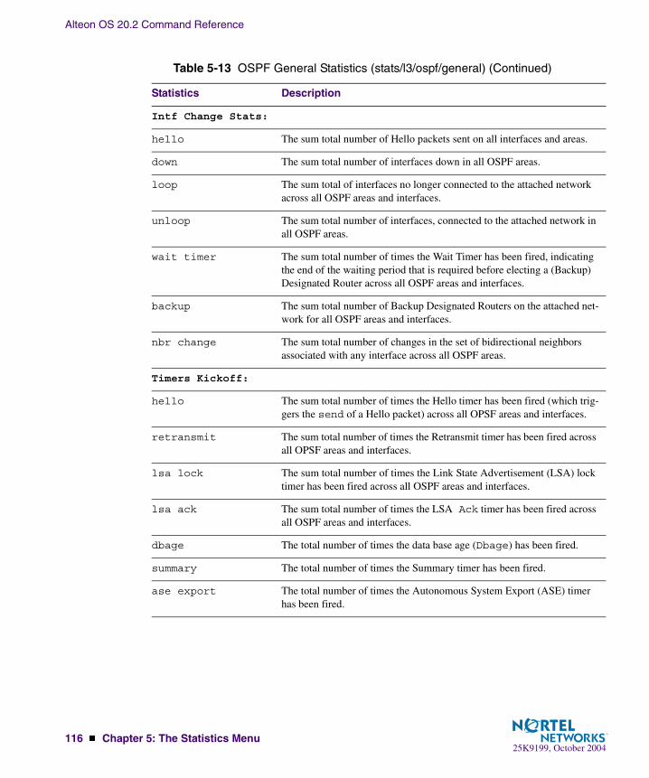
Alteon OS 20.2 Command Reference
116 � Chapter 5: The Statistics Menu25K9199, October 2004
Intf Change Stats:
hello The sum total number of Hello packets sent on all interfaces and areas.
down The sum total number of interfaces down in all OSPF areas.
loop The sum total of interfaces no longer connected to the attached network across all OSPF areas and interfaces.
unloop The sum total number of interfaces, connected to the attached network in all OSPF areas.
wait timer The sum total number of times the Wait Timer has been fired, indicating the end of the waiting period that is required before electing a (Backup) Designated Router across all OSPF areas and interfaces.
backup The sum total number of Backup Designated Routers on the attached net-work for all OSPF areas and interfaces.
nbr change The sum total number of changes in the set of bidirectional neighbors associated with any interface across all OSPF areas.
Timers Kickoff:
hello The sum total number of times the Hello timer has been fired (which trig-gers the send of a Hello packet) across all OPSF areas and interfaces.
retransmit The sum total number of times the Retransmit timer has been fired across all OPSF areas and interfaces.
lsa lock The sum total number of times the Link State Advertisement (LSA) lock timer has been fired across all OSPF areas and interfaces.
lsa ack The sum total number of times the LSA Ack timer has been fired across all OSPF areas and interfaces.
dbage The total number of times the data base age (Dbage) has been fired.
summary The total number of times the Summary timer has been fired.
ase export The total number of times the Autonomous System Export (ASE) timer has been fired.
Table 5-13 OSPF General Statistics (stats/l3/ospf/general) (Continued)
Statistics Description

Alteon OS 20.2 Command Reference
Chapter 5: The Statistics Menu � 11725K9199, October 2004
/stats/l3/ipIP Statistics
IP statistics:ipInReceives: 3115873 ipInHdrErrors: 1ipInAddrErrors: 35447 ipForwDatagrams: 0ipInUnknownProtos: 500504 ipInDiscards: 0ipInDelivers: 2334166 ipOutRequests: 1010542ipOutDiscards: 4 ipOutNoRoutes: 4ipReasmReqds: 0 ipReasmOKs: 0ipReasmFails: 0 ipFragOKs: 0ipFragFails: 0 ipFragCreates: 0ipRoutingDiscards: 0 ipDefaultTTL: 255ipReasmTimeout: 5
Table 5-14 IP Statistics (stats/l3/ip)
Statistics Description
ipInReceives The total number of input datagrams received from interfaces, including those received in error.
ipInHdrErrors The number of input datagrams discarded due to errors in their IP head-ers, including bad checksums, version number mismatch, other format errors, time-to-live exceeded, errors discovered in processing their IP options, and so forth.
ipInAddrErrors The number of input datagrams discarded because the IP address in their IP header’s destination field was not a valid address to be received at this entity (the switch). This count includes invalid addresses (for example, 0.0.0.0) and addresses of unsupported Classes (for example, Class E). For entities which are not IP Gateways and therefore do not forward data-grams, this counter includes datagrams discarded because the destination address was not a local address.
ipForwDatagrams The number of input datagrams for which this entity (the switch) was not their final IP destination, as a result of which an attempt was made to find a route to forward them to that final destination. In entities which do not act as IP Gateways, this counter will include only those packets, which were Source-Routed via this entity (the switch), and the Source- Route option processing was successful.
ipInUnknownProtos The number of locally addressed datagrams received successfully but dis-carded because of an unknown or unsupported protocol.

Alteon OS 20.2 Command Reference
118 � Chapter 5: The Statistics Menu25K9199, October 2004
ipInDiscards The number of input IP datagrams for which no problems were encoun-tered to prevent their continued processing, but which were discarded (for example, for lack of buffer space). Note that this counter does not include any datagrams discarded while awaiting re-assembly.
ipInDelivers The total number of input datagrams successfully delivered to IP user-protocols (including ICMP).
ipOutRequests The total number of IP datagrams which local IP user-protocols (includ-ing ICMP) supplied to IP in requests for transmission. Note that this counter does not include any datagrams counted in ipForwDatagrams.
ipOutDiscards The number of output IP datagrams for which no problem was encountered to prevent their transmission to their destination, but which were discarded (for example, for lack of buffer space). Note that this counter would include datagrams counted in ipForwDatagrams if any such packets met this (discretionary) discard criterion.
ipOutNoRoutes The number of IP datagrams discarded because no route could be found to transmit them to their destination. Note that this counter includes any packets counted in ipForwDatagrams, which meet this no-route crite-rion. Note that this includes any datagrams which a host cannot route because all of its default gateways are down.
ipReasmReqds The number of IP fragments received which needed to be reassembled at this entity (the switch).
ipReasmOKs The number of IP datagrams successfully re- assembled.
ipReasmFails The number of failures detected by the IP re- assembly algorithm (for whatever reason: timed out, errors, and so forth). Note that this is not nec-essarily a count of discarded IP fragments since some algorithms (notably the algorithm in RFC 815) can lose track of the number of fragments by combining them as they are received.
ipFragOKs The number of IP datagrams that have been successfully fragmented at this entity (the switch).
ipFragFails The number of IP datagrams that have been discarded because they needed to be fragmented at this entity (the switch) but could not be, for example, because their Don’t Fragment flag was set.
ipFragCreates The number of IP datagram fragments that have been generated as a result of fragmentation at this entity (the switch).
Table 5-14 IP Statistics (stats/l3/ip)
Statistics Description

Alteon OS 20.2 Command Reference
Chapter 5: The Statistics Menu � 11925K9199, October 2004
/stats/l3/routeRoute Statistics
ipRoutingDiscards The number of routing entries, which were chosen to be discarded even though they are valid. One possible reason for discarding such an entry could be to free-up buffer space for other routing entries.
ipDefaultTTL The default value inserted into the Time-To-Live (TTL) field of the IP header of datagrams originated at this entity (the switch), whenever a TTL value is not supplied by the transport layer protocol.
ipReasmTimeout The maximum number of seconds, which received fragments are held while they are awaiting reassembly at this entity (the switch).
Route statistics:ipRoutesCur: 7 ipRoutesHighWater: 7ipRoutesMax: 1024
RIP statistics:ripInPkts: 0 ripOutPkts: 0ripBadPkts: 0 ripRoutesAgedOut: 0
BGP statistics:bgpInPkts: 0 bgpOutPkts: 0bgpBadPkts: 0 bgpSessFailures: 0bgpRoutesAdded: 0 bgpRoutesRemoved: 0bgpRoutesCur: 0 bgpRoutesFailed: 0bgpRoutesIgnored: 0 bgpRoutesFiltered: 0
Table 5-15 Route Statistics (/stats/l3/route)
Statistics Description
ipRoutesCur The total number of outstanding routes in the route table.
ipRoutesHighWater The highest number of routes ever recorded in the route table.
ipRoutesMax The maximum number of routes that are supported.
RIP statistics:
ripInPkts The total number of good RIP advertisement packets received.
Table 5-14 IP Statistics (stats/l3/ip)
Statistics Description

Alteon OS 20.2 Command Reference
120 � Chapter 5: The Statistics Menu25K9199, October 2004
/stats/l3/arpARP statistics
This menu option enables you to display Address Resolution Protocol statistics.
ripOutPkts The total number of RIP advertisement packets sent.
ripBadPkts The total number of RIP advertisement packets received that were dropped.
ripRoutesAgedOut The total number of routes learned via RIP that has aged out.
BGP statistics:
bgpInPkts The total number of BGP packets received.
bgpOutPkts The total number of BGP packets sent.
bgpBadPkts The total number of BGP packets dropped.
bgpSessFailures The total number of failed sessions.
bgpRoutesAdded The total number of routes that were added to the routing table.
bgpRoutesRemoved The total number of routes that were removed from the routing table.
bgpRoutesCur The total number of current BGP routes.
bgpRoutesFailed The total number of BGP routes that failed to add in the routing table.
bgpRoutesIgnored The total number of routes ignored because the peer was not con-nected locally or multihop was not configured.
bgpRoutesFiltered The total number of routes dropped by the filter.
ARP statistics:arpEntriesCur: 3 arpEntriesHighWater: 4arpEntriesMax: 4096
Table 5-16 ARP Statistics (/stats/l3/arp)
Statistics Description
arpEntriesCur The total number of outstanding ARP entries in the ARP table.
Table 5-15 Route Statistics (/stats/l3/route)
Statistics Description

Alteon OS 20.2 Command Reference
Chapter 5: The Statistics Menu � 12125K9199, October 2004
/stats/l3/vrrpVRRP Statistics
Virtual Router Redundancy Protocol (VRRP) support on the GbE Switch Module provides redundancy between routers in a LAN. This is accomplished by configuring the same virtual router IP address and ID number on each participating VRRP-capable routing device. One of the virtual routers is then elected as the master, based on a number of priority criteria, and assumes control of the shared virtual router IP address. If the master fails, one of the backup virtual routers will assume routing authority and take control of the virtual router IP address.
When virtual routers are configured, you can display the following protocol statistics for VRRP:
� Advertisements received (vrrpInAdvers)
� Advertisements transmitted (vrrpOutAdvers)
� Advertisements received, but ignored (vrrpBadAdvers)
The statistics for the VRRP LAN are displayed:
arpEntriesHighWater The highest number of ARP entries ever recorded in the ARP table.
arpEntriesMax The maximum number of ARP entries that are supported.
VRRP statistics:vrrpInAdvers: 0 vrrpBadAdvers: 0vrrpOutAdvers: 0
Table 5-17 VRRP Statistics (/stats/l3/vrrp)
Statistics Description
vrrpInAdvers The total number of VRRP advertisements that have been received.
vrrpBadAdvers The total number of VRRP advertisements received that were dropped.
vrrpOutAdvers The total number of VRRP advertisements that have been sent.
Table 5-16 ARP Statistics (/stats/l3/arp)
Statistics Description
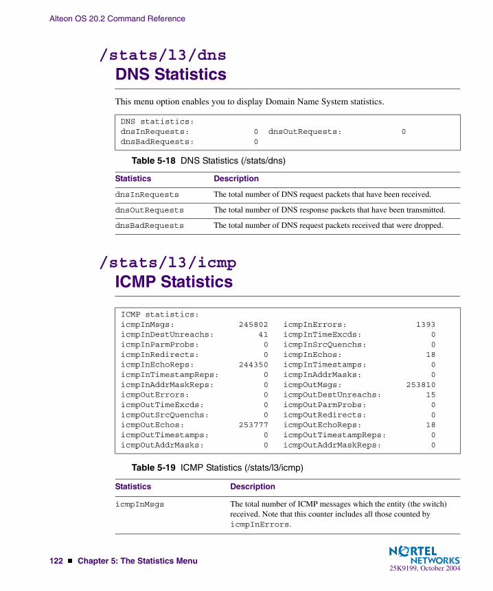
Alteon OS 20.2 Command Reference
122 � Chapter 5: The Statistics Menu25K9199, October 2004
/stats/l3/dnsDNS Statistics
This menu option enables you to display Domain Name System statistics.
/stats/l3/icmpICMP Statistics
DNS statistics:dnsInRequests: 0 dnsOutRequests: 0dnsBadRequests: 0
Table 5-18 DNS Statistics (/stats/dns)
Statistics Description
dnsInRequests The total number of DNS request packets that have been received.
dnsOutRequests The total number of DNS response packets that have been transmitted.
dnsBadRequests The total number of DNS request packets received that were dropped.
ICMP statistics:icmpInMsgs: 245802 icmpInErrors: 1393icmpInDestUnreachs: 41 icmpInTimeExcds: 0icmpInParmProbs: 0 icmpInSrcQuenchs: 0icmpInRedirects: 0 icmpInEchos: 18icmpInEchoReps: 244350 icmpInTimestamps: 0icmpInTimestampReps: 0 icmpInAddrMasks: 0icmpInAddrMaskReps: 0 icmpOutMsgs: 253810icmpOutErrors: 0 icmpOutDestUnreachs: 15icmpOutTimeExcds: 0 icmpOutParmProbs: 0icmpOutSrcQuenchs: 0 icmpOutRedirects: 0icmpOutEchos: 253777 icmpOutEchoReps: 18icmpOutTimestamps: 0 icmpOutTimestampReps: 0icmpOutAddrMasks: 0 icmpOutAddrMaskReps: 0
Table 5-19 ICMP Statistics (/stats/l3/icmp)
Statistics Description
icmpInMsgs The total number of ICMP messages which the entity (the switch) received. Note that this counter includes all those counted by icmpInErrors.
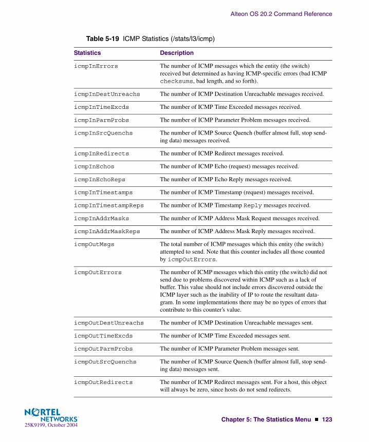
Alteon OS 20.2 Command Reference
Chapter 5: The Statistics Menu � 12325K9199, October 2004
icmpInErrors The number of ICMP messages which the entity (the switch) received but determined as having ICMP-specific errors (bad ICMP checksums, bad length, and so forth).
icmpInDestUnreachs The number of ICMP Destination Unreachable messages received.
icmpInTimeExcds The number of ICMP Time Exceeded messages received.
icmpInParmProbs The number of ICMP Parameter Problem messages received.
icmpInSrcQuenchs The number of ICMP Source Quench (buffer almost full, stop send-ing data) messages received.
icmpInRedirects The number of ICMP Redirect messages received.
icmpInEchos The number of ICMP Echo (request) messages received.
icmpInEchoReps The number of ICMP Echo Reply messages received.
icmpInTimestamps The number of ICMP Timestamp (request) messages received.
icmpInTimestampReps The number of ICMP Timestamp Reply messages received.
icmpInAddrMasks The number of ICMP Address Mask Request messages received.
icmpInAddrMaskReps The number of ICMP Address Mask Reply messages received.
icmpOutMsgs The total number of ICMP messages which this entity (the switch) attempted to send. Note that this counter includes all those counted by icmpOutErrors.
icmpOutErrors The number of ICMP messages which this entity (the switch) did not send due to problems discovered within ICMP such as a lack of buffer. This value should not include errors discovered outside the ICMP layer such as the inability of IP to route the resultant data-gram. In some implementations there may be no types of errors that contribute to this counter’s value.
icmpOutDestUnreachs The number of ICMP Destination Unreachable messages sent.
icmpOutTimeExcds The number of ICMP Time Exceeded messages sent.
icmpOutParmProbs The number of ICMP Parameter Problem messages sent.
icmpOutSrcQuenchs The number of ICMP Source Quench (buffer almost full, stop send-ing data) messages sent.
icmpOutRedirects The number of ICMP Redirect messages sent. For a host, this object will always be zero, since hosts do not send redirects.
Table 5-19 ICMP Statistics (/stats/l3/icmp)
Statistics Description

Alteon OS 20.2 Command Reference
124 � Chapter 5: The Statistics Menu25K9199, October 2004
/stats/l3/igmpIGMP Statistics
This menu option enables you to display statistics regarding the use of the IGMP Multicast Groups.
IGMP statistics are described in the following table:
icmpOutEchos The number of ICMP Echo (request) messages sent.
icmpOutEchoReps The number of ICMP Echo Reply messages sent.
icmpOutTimestamps The number of ICMP Timestamp (request) messages sent.
icmpOutTimestampReps The number of ICMP Timestamp Reply messages sent.
icmpOutAddrMasks The number of ICMP Address Mask Request messages sent.
icmpOutAddrMaskReps The number of ICMP Address Mask Reply messages sent.
IGMP Snoop vlan 1 statistics:------------------------------------------------------------------rxIgmpValidPkts: 0 rxIgmpInvalidPkts: 0rxIgmpGenQueries: 0 rxIgmpGrpSpecificQueries: 0rxIgmpLeaves: 0 rxIgmpReports: 0txIgmpReports: 0 txIgmpGrpSpecificQueries: 0txIgmpLeaves: 0Current Groups: 0 Current M-cast Routers: 1
Table 5-20 IGMP Statistics (/stats/igmp)
Statistic Description
rxIgmpValidPkts Total number of valid IGMP packets received
rxIgmpInvalidPkts Total number of invalid packets received
rxIgmpGenQueries Total number of General Membership Query packets received
rxIgmpGrpSpecificQueries Total number of Membership Query packets received from specific groups
Table 5-19 ICMP Statistics (/stats/l3/icmp)
Statistics Description

Alteon OS 20.2 Command Reference
Chapter 5: The Statistics Menu � 12525K9199, October 2004
/stats/l3/if <interface number>Interface Statistics
rxIgmpLeaves Total number of Leave requests received
rxIgmpReports Total number of Membership Reports received
txIgmpReports Total number of Membership reports transmitted
txIgmpGrpSpecificQueries Total number of Membership Query packets transmitted to specific groups
txIgmpLeaves Total number of Leave messages transmitted
Current Groups Total number of active IGMP groups learned through IGMP Snooping
Current M-Cast Routers Total number of static Multicast Routers configured on the switch
IP interface 1 statistics:ifInOctets: 48948386 ifInUcastPkts: 220553ifInNUCastPkts: 167895 ifInDiscards: 0ifInErrors: 0 ifInUnknownProtos: 0ifOutOctets: 27100789 ifOutUcastPkts: 441938ifOutNUcastPkts: 218652 ifOutDiscards: 0ifOutErrors: 0 ifStateChanges 1
Table 5-21 Interface Statistics (/stats/l3/if)
Statistics Description
ifInOctets The total number of octets received on the interface, including framing characters.
ifInUcastPkts The number of packets, delivered by this sub-layer to a higher (sub- layer), which were not addressed to a multicast or broadcast address at this sub-layer.
Table 5-20 IGMP Statistics (/stats/igmp)
Statistic Description
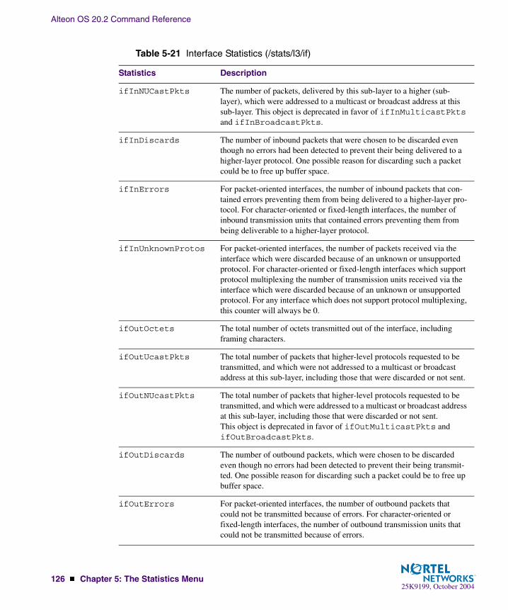
Alteon OS 20.2 Command Reference
126 � Chapter 5: The Statistics Menu25K9199, October 2004
ifInNUCastPkts The number of packets, delivered by this sub-layer to a higher (sub- layer), which were addressed to a multicast or broadcast address at this sub-layer. This object is deprecated in favor of ifInMulticastPkts and ifInBroadcastPkts.
ifInDiscards The number of inbound packets that were chosen to be discarded even though no errors had been detected to prevent their being delivered to a higher-layer protocol. One possible reason for discarding such a packet could be to free up buffer space.
ifInErrors For packet-oriented interfaces, the number of inbound packets that con-tained errors preventing them from being delivered to a higher-layer pro-tocol. For character-oriented or fixed-length interfaces, the number of inbound transmission units that contained errors preventing them from being deliverable to a higher-layer protocol.
ifInUnknownProtos For packet-oriented interfaces, the number of packets received via the interface which were discarded because of an unknown or unsupported protocol. For character-oriented or fixed-length interfaces which support protocol multiplexing the number of transmission units received via the interface which were discarded because of an unknown or unsupported protocol. For any interface which does not support protocol multiplexing, this counter will always be 0.
ifOutOctets The total number of octets transmitted out of the interface, including framing characters.
ifOutUcastPkts The total number of packets that higher-level protocols requested to be transmitted, and which were not addressed to a multicast or broadcast address at this sub-layer, including those that were discarded or not sent.
ifOutNUcastPkts The total number of packets that higher-level protocols requested to be transmitted, and which were addressed to a multicast or broadcast address at this sub-layer, including those that were discarded or not sent.This object is deprecated in favor of ifOutMulticastPkts and ifOutBroadcastPkts.
ifOutDiscards The number of outbound packets, which were chosen to be discarded even though no errors had been detected to prevent their being transmit-ted. One possible reason for discarding such a packet could be to free up buffer space.
ifOutErrors For packet-oriented interfaces, the number of outbound packets that could not be transmitted because of errors. For character-oriented or fixed-length interfaces, the number of outbound transmission units that could not be transmitted because of errors.
Table 5-21 Interface Statistics (/stats/l3/if)
Statistics Description
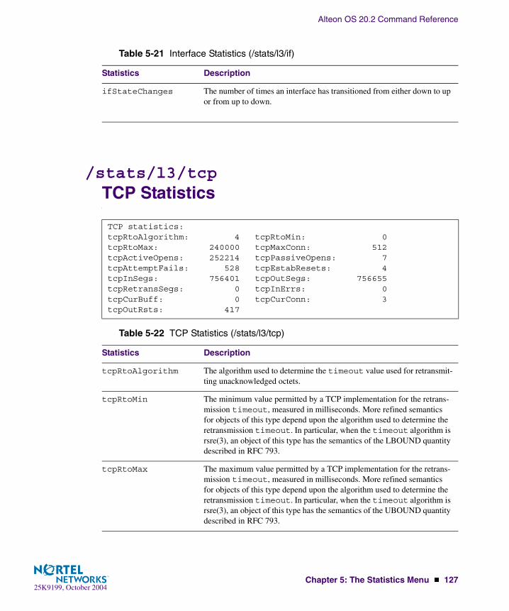
Alteon OS 20.2 Command Reference
Chapter 5: The Statistics Menu � 12725K9199, October 2004
/stats/l3/tcpTCP Statistics
ifStateChanges The number of times an interface has transitioned from either down to up or from up to down.
TCP statistics:tcpRtoAlgorithm: 4 tcpRtoMin: 0tcpRtoMax: 240000 tcpMaxConn: 512tcpActiveOpens: 252214 tcpPassiveOpens: 7tcpAttemptFails: 528 tcpEstabResets: 4tcpInSegs: 756401 tcpOutSegs: 756655tcpRetransSegs: 0 tcpInErrs: 0tcpCurBuff: 0 tcpCurConn: 3tcpOutRsts: 417
Table 5-22 TCP Statistics (/stats/l3/tcp)
Statistics Description
tcpRtoAlgorithm The algorithm used to determine the timeout value used for retransmit-ting unacknowledged octets.
tcpRtoMin The minimum value permitted by a TCP implementation for the retrans-mission timeout, measured in milliseconds. More refined semantics for objects of this type depend upon the algorithm used to determine the retransmission timeout. In particular, when the timeout algorithm is rsre(3), an object of this type has the semantics of the LBOUND quantity described in RFC 793.
tcpRtoMax The maximum value permitted by a TCP implementation for the retrans-mission timeout, measured in milliseconds. More refined semantics for objects of this type depend upon the algorithm used to determine the retransmission timeout. In particular, when the timeout algorithm is rsre(3), an object of this type has the semantics of the UBOUND quantity described in RFC 793.
Table 5-21 Interface Statistics (/stats/l3/if)
Statistics Description

Alteon OS 20.2 Command Reference
128 � Chapter 5: The Statistics Menu25K9199, October 2004
tcpMaxConn The limit on the total number of TCP connections the entity (the switch) can support. In entities where the maximum number of connections is dynamic, this object should contain the value -1.
tcpActiveOpens The number of times TCP connections have made a direct transition to the SYN-SENT state from the CLOSED state.
tcpPassiveOpens The number of times TCP connections have made a direct transition to the SYN-RCVD state from the LISTEN state.
tcpAttemptFails The number of times TCP connections have made a direct transition to the CLOSED state from either the SYN-SENT state or the SYN-RCVD state, plus the number of times TCP connections have made a direct tran-sition to the LISTEN state from the SYN-RCVD state.
tcpEstabResets The number of times TCP connections have made a direct transition to the CLOSED state from either the ESTABLISHED state or the CLOSE-WAIT state.
tcpInSegs The total number of segments received, including those received in error. This count includes segments received on currently established connec-tions.
tcpOutSegs The total number of segments sent, including those on current connec-tions but excluding those containing only retransmitted octets.
tcpRetransSegs The total number of segments retransmitted - that is, the number of TCP segments transmitted containing one or more previously transmitted octets.
tcpInErrs The total number of segments received in error (for example, bad TCP checksums).
tcpCurBuff The total number of outstanding memory allocations from heap by TCP protocol stack.
tcpCurConn The total number of outstanding TCP sessions that are currently opened.
tcpOutRsts The number of TCP segments sent containing the RST flag.
Table 5-22 TCP Statistics (/stats/l3/tcp)
Statistics Description

Alteon OS 20.2 Command Reference
Chapter 5: The Statistics Menu � 12925K9199, October 2004
/stats/l3/udpUDP Statistics
UDP statistics:udpInDatagrams: 54 udpOutDatagrams: 43udpInErrors: 0 udpNoPorts: 1578077
Table 5-23 UDP Statistics (/stats/l3/udp)
Statistics Description
udpInDatagrams The total number of UDP datagrams delivered to the switch.
udpOutDatagrams The total number of UDP datagrams sent from this entity (the switch).
udpInErrors The number of received UDP datagrams that could not be delivered for reasons other than the lack of an application at the destination port.
udpNoPorts The total number of received UDP datagrams for which there was no application at the destination port.

Alteon OS 20.2 Command Reference
130 � Chapter 5: The Statistics Menu25K9199, October 2004
/stats/slbLoad Balancing Statistics Menu
[Server Load Balancing Statistics Menu] sp - SLB Switch SP Stats Menu real - Show real server stats group - Show real server group stats virt - Show virtual server stats filt - Show filter stats layer7 - Show Layer 7 stats ssl - Show SSL SLB stats ftp - Show FTP SLB parsing and NAT stats rtsp - Show RTSP SLB stats dns - Show DNS SLB stats wap - Show WAP SLB stats tcp - Show TCP rate limiting stats maint - Show maintenance stats clear - Clear non-operational Server Load Balancing stats aux - Show auxiliary session table stats dump - Dump all SLB statistics
Table 5-24 SLB Statistics Menu Options (/stats/slb)
Command Syntax and Usage
sp <SP number (1-4)>Displays the server load balancing statistics menu. To view menu options, see page 132.
real <real server number (1-63)>Displays the following real server statistics:
� Number of times the real server has failed its health checks� Number of sessions currently open on the real server� Total sessions the real server was assigned� Highest number of simultaneous sessions recorded for each real server� Real server transmit/receive octetsSee page 133 for sample output.
group <real server group number (1-64)>Displays the following real server group statistics:
� Current and total sessions for each real server in the real server group.� Current and total sessions for all real servers associated with the real server group.� Highest number of simultaneous sessions recorded for each real server.� Real server transmit/receive octets. For per-service octet counters, see page 135.See page 136 for sample output.

Alteon OS 20.2 Command Reference
Chapter 5: The Statistics Menu � 13125K9199, October 2004
virt <virtual server number (1-64)>Displays the following virtual server statistics:
� Current and total sessions for each real server associated with the virtual server.� Current and total sessions for all real servers associated with the virtual server.� Highest number of simultaneous sessions recorded for each real server.� Real server transmit/receive octets. For per-service octet counters, see page 135.See page 137 for sample output.
filt <filter ID (1-1024)>Displays the total number of times any filter has been used. See page 137 for sample output.
layer7
Displays Layer 7 statistics. See page 138 for sample output.
ssl
Displays SSL server load balancing statistics. See page 142 for sample output.
ftp
Displays FTP SLB parsing and NAT statistics. See page 143 for sample output.
rtsp
Displays RTSP SLB statistics. See page 146 for sample output.
dns
Displays DNS SLB statistics. See page 146 for sample output.
wap
Displays WAP SLB statistics. See page 148 for sample output.
tcp
Displays statistics for TCP rate limiting. See page 150 for sample output.
maint
Displays SLB maintenance statistics. See page 150 for sample output.
clear [y|n]Clears all non-operating SLB statistics on the GbE Switch Module, resetting them to zero. This command does not reset the switch and does not affect the following counters:
� Counters required for Layer 4 and Layer 7 operation (such as current real server sessions).� All related SNMP counters.To view the statistics reset by this command, refer to Table 5-42 on page 152.
aux
Displays auxiliary session table statistics.
Table 5-24 SLB Statistics Menu Options (/stats/slb)
Command Syntax and Usage

Alteon OS 20.2 Command Reference
132 � Chapter 5: The Statistics Menu25K9199, October 2004
/stats/slb/spServer Load Balancing SP statistics Menu
dump
Dumps all switch SLB statistics. Use this command to gather data for tuning and debugging switch performance. To save dump data to a file, set your communication software on your workstation to capture session data prior to issuing the dump command.
[Server Load Balancing SP Statistics Menu] real - Show real server stats group - Show real server group stats virt - Show virtual server stats filt - Show filter stats maint - Show maintenance stats aux - Show auxiliary session table stats clear - Clear SP stats
Table 5-25 SP Statistics Menu options (/stats/slb/sp)
Command Syntax and Usage
real <real server number (1-63)>Displays real server statistics of the switch port. See page 133 for a sample output.
group <real server group number (1-64)>Displays real server group statistics of the switch port. See page 133 for a sample output.
virt <virtual server number (1-64)>Displays statistics of the virtual server. See page 133 for a sample output.
filt <filter ID (1-1024)>Displays statistics of the filter. See page 134 for a sample output.
maint
Displays the SP maintenance statistics. See page 134 for a sample output.
aux
Displays the statistics of the auxiliary session table.
clear
Deletes all the SP statistics.
Table 5-24 SLB Statistics Menu Options (/stats/slb)
Command Syntax and Usage

Alteon OS 20.2 Command Reference
Chapter 5: The Statistics Menu � 13325K9199, October 2004
/stats/slb/sp/real <real server number>SP Real Server Statistics
/stats/slb/sp <sp number>/group <real group server number>
SP Real Group Server Statistics
/stats/slb/sp <sp number>/virt <virtual server number>
SP Virtual Server Statistics
Port 1 Real server 1 stats:Current sessions: 3Total sessions: 3Octets: 24
Real server group 1 stats: Current Total HighestReal IP address Sessions Sessions Sessions Octets---- --------------- -------- ---------- -------- --------------- 1 200.100.10.14 20 60 9 480000 2 200.100.10.15 20 77 12 616000---- --------------- -------- ---------- -------- --------------- 40 137 21 1096000
Real server group 1 stats: Current Total HighestReal IP address Sessions Sessions Sessions Octets---- --------------- -------- ---------- -------- --------------- 1 200.100.10.14 20 60 9 480000 2 200.100.10.15 20 77 12 616000---- --------------- -------- ---------- -------- --------------- 200.100.10.100 40 137 21 1096000
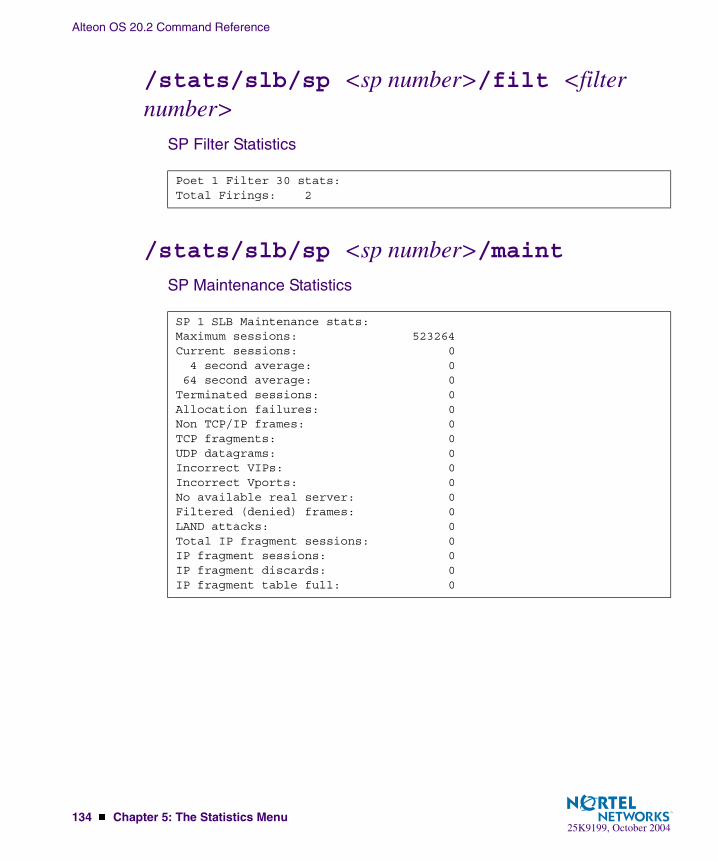
Alteon OS 20.2 Command Reference
134 � Chapter 5: The Statistics Menu25K9199, October 2004
/stats/slb/sp <sp number>/filt <filter number>
SP Filter Statistics
/stats/slb/sp <sp number>/maint
SP Maintenance Statistics
Poet 1 Filter 30 stats:Total Firings: 2
SP 1 SLB Maintenance stats:Maximum sessions: 523264Current sessions: 0 4 second average: 0 64 second average: 0Terminated sessions: 0Allocation failures: 0Non TCP/IP frames: 0TCP fragments: 0UDP datagrams: 0Incorrect VIPs: 0Incorrect Vports: 0No available real server: 0Filtered (denied) frames: 0LAND attacks: 0Total IP fragment sessions: 0IP fragment sessions: 0IP fragment discards: 0IP fragment table full: 0

Alteon OS 20.2 Command Reference
Chapter 5: The Statistics Menu � 13525K9199, October 2004
/stats/slb/real <real server number>Real Server SLB Statistics
NOTE – Octets are provided per server, not per service, unless configured as described in “Per Service Octet Counters” on page 135.
Per Service Octet Counters
For each load-balanced real server, the octet counters represent the combined number of trans-mit and receive bytes (octets). These counters are then added to report the total octets for each virtual server.
The octet counters are provided per server–not per service. If you need octet counters on a per-service basis, you can accomplish this through the following configuration:
1. Configure a separate IP address for each service on each server being load balanced.
For instance, you can configure IP address 10.1.1.20 for HTTP services, and 10.1.1.21 for FTP services on the same physical server.
Real server 1 stats:Health check failures: 0Current sessions: 129Total sessions: 65478Highest sessions: 4343Octets 523824000
Table 5-26 Real Server SLB Statistics (/stats/slb/real)
Statistics Description
Current sessions The total number of outstanding sessions that are established to the par-ticular real server.
Total sessions The total number of sessions that have been established to the particular real server.
Highest sessions The highest number of sessions ever recorded for the particular real server.
Octets The total number of octets sent by the particular real server.

Alteon OS 20.2 Command Reference
136 � Chapter 5: The Statistics Menu25K9199, October 2004
2. On the GbE Switch Module, configure a real server with a real IP address for each ser-vice above.
Continuing the example above, two real servers would be configured for the physical server (representing each real service). If there were five physical servers providing the two services (HTTP and FTP), 10 real servers would have to be configured: five for the HTTP services on each physical server, and five for the FTP services on each physical server.
3. On the GbE Switch Module, configure one real server group for each type of service, and group each appropriate real server IP address into the group that handles the specific service.
Thus, in keeping with our example, two groups would be configured: one for handling HTTP and one for handling FTP.
4. Configure a virtual server and add the appropriate services to that virtual server.
/stats/slb/group <real server group number>Real Server Group Statistics
Real server group statistics include the following:
� Current and total sessions for each real server in the real server group.
� Current and total sessions for all real servers associated with the real server group.
� Highest number of simultaneous sessions recorded for each real server.
� Real server transmit/receive octets. For per-service octet counters, see the procedure on “Per Service Octet Counters” on page 135.
Real server group 1 stats: Current Total HighestReal IP address Sessions Sessions Sessions Octets---- --------------- -------- ---------- -------- --------------- 1 200.100.10.14 20 60 9 480000 2 200.100.10.15 20 77 12 616000---- --------------- -------- ---------- -------- --------------- 40 137 21 1096000

Alteon OS 20.2 Command Reference
Chapter 5: The Statistics Menu � 13725K9199, October 2004
/stats/slb/virt <virtual server number>Virtual Server SLB Statistics
NOTE – The virtual server IP address is shown on the last line, below the real server IP addresses.
Virtual server statistics include the following:
� Current and total sessions for each real server associated with the virtual server.
� Current and total sessions for all real servers associated with the virtual server.
� Highest number of simultaneous sessions recorded for each real server.
� Real server transmit/receive octets. For per-service octet counters, see “Per Service Octet Counters” on page 135.
/stats/slb/filt <filter number>Filter SLB Statistics
You can obtain the total number of times any filter has been used.
Virtual server 1 stats: Current Total HighestReal IP address Sessions Sessions Sessions Octets---- --------------- -------- ---------- -------- --------------- 1 200.100.10.14 20 60 9 480000 2 200.100.10.15 20 77 12 616000---- --------------- -------- ---------- -------- --------------- 200.100.10.20 40 309 21 1096000
Filter 1 stats:Total firings: 1011

Alteon OS 20.2 Command Reference
138 � Chapter 5: The Statistics Menu25K9199, October 2004
/stats/slb/layer7SLB Layer7 Statistics Menu
/stats/slb/layer7/redirLayer7 Redirection Statistics
[Layer 7 Statistics Menu] redir - Show URL Redirection stats str - Show SLB String stats maint - Show Layer 7 Maintenance stats
Table 5-27 SLB Layer 7 Statistics Menu Options (/stats/slb/layer7)
Command Syntax & Usage
redir
Displays URL Redirection statistics. See page 138 for a sample output.
str
Displays SLB string statistics. See page 139 for a sample output.
maint
Displays Layer 7 maintenance statistics. See page 140 for a sample output.
Total URL based web cache redirection stats:Total cache server hits: 0Total origin server hits: 0Total straight to origin server hits: 0Total none-GETs hits: 0Total ’Cookie: ’ hits: 0Total no-cache hits: 0
Table 5-28 Layer 7 Redirection Statistics (/stats/slb/layer7/redir)
Statistics Description
Total cache server hits The total number of HTTP requests redirected to the cache server.
Total origin server hits The total number of HTTP requests forwarded to the origin server.
Total straight to ori-gin server hits
The total number of HTTP requests forwarded from straight to the origin server.
Total none-GETs hits The total number of none GET requests forwarded to the origin server.
Total ’Cookie:’ hits The total number of cookie requests forwarded to the origin server.

Alteon OS 20.2 Command Reference
Chapter 5: The Statistics Menu � 13925K9199, October 2004
/stats/slb/layer7/strLayer 7 SLB String Statistics
Total no-cache hits The total number of requests containing no-cache header forwarded to the origin server.
SLB String stats: ID SLB String Hits 1 any 1527115 2 www.[abcdefghijklm]*.com 0 3 www.[nopqrstuvwxyz]*.com 0 4 www.junk.com 0 5 www.abc.com 0 6 www.[abcdefjhijklm]*.org 0 7 www.[nopqrstuvwxyz]*.org 0
Table 5-29 Layer 7 SLB String Statistics (/stats/slb/layer7/str)
Statistics Description
ID SLB String The user-defined strings being used in URL matching.
Hits The total number of instances that are load-balanced due to matching of the particular URL ID.
Table 5-28 Layer 7 Redirection Statistics (/stats/slb/layer7/redir)
Statistics Description

Alteon OS 20.2 Command Reference
140 � Chapter 5: The Statistics Menu25K9199, October 2004
/stats/slb/layer7/maintLayer 7 SLB Maintenance Statistics
Clients reset by switch on server side: 0Connection Splicing to support HTTP/1.1: 0Half open connections: 0Switch retries: 0Random early drops: 0Requests exceeded 4500 bytes: 0Invalid 3-way handshakes: 0Current SP[1] memory units: 327 Lowest: 327Current SP[2] memory units: 327 Lowest: 327Current SP[3] memory units: 327 Lowest: 327Current SP[4] memory units: 327 Lowest: 327Current SP memory units: 1308Current SEQ buffer entries: 0 Highest: 0Current Data buffer use: 0 Highest: 0Current SP buffer entries: 0 Highest: 0Total Nonzero SEQ Alloc: 0Total SEQ Buffer Allocs: 0 Total SEQ Frees: 0Total Data Buffer Allocs: 0 Total Data Frees: 0Alloc Fails - Seq buffers: 0 Alloc Fails - Ubufs: 0Max sessions per bucket: 0 Max frames per session: 0Max bytes buffered (sess): 0
Table 5-30 SLB Layer 7 Maintenance Statistics (/stats/slb/layer7/maint)
Statistics Description
Clients reset by switch on server side
The number of reset frames sent to the server by the switch during server connection termination.
Connection Splicing to support HTTP/1.1
The total number of connection swapping between different real servers in supporting multiple HTTP/1.1 client requests.
Half open connections The total numbers of outstanding TCP connections that are half opened. It is incremented when the switch responds to TCP SYN packet and decremented upon receiving TCP SYN ACK packet from the requester.
Switch retries The total number of switch retries to connect to the real server.
Random early drops The total number of SYN frames dropped when the buffer is low.
Requests exceeded 4500 bytes
The total number of GET requests that exceeded 4500 bytes.
Invalid 3-way hand-shakes
The total number of dropped frames because of invalid 3-way hand shakes.
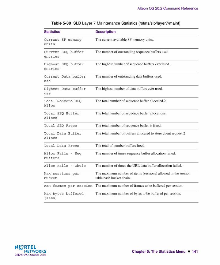
Alteon OS 20.2 Command Reference
Chapter 5: The Statistics Menu � 14125K9199, October 2004
Current SP memory units
The current available SP memory units.
Current SEQ buffer entries
The number of outstanding sequence buffers used.
Highest SEQ buffer entries
The highest number of sequence buffers ever used.
Current Data buffer use
The number of outstanding data buffers used.
Highest Data buffer use
The highest number of data buffers ever used.
Total Nonzero SEQ Alloc
The total number of sequence buffer allocated.2
Total SEQ Buffer Allocs
The total number of sequence buffer allocations.
Total SEQ Frees The total number of sequence buffer is freed.
Total Data Buffer Allocs
The total number of buffers allocated to store client request.2
Total Data Frees The total of number buffers freed.
Alloc Fails - Seq buffers
The number of times sequence buffer allocation failed.
Alloc Fails - Ubufs The number of times the URL data buffer allocation failed.
Max sessions per bucket
The maximum number of items (sessions) allowed in the session table hash bucket chain.
Max frames per session The maximum number of frames to be buffered per session.
Max bytes buffered (sess)
The maximum number of bytes to be buffered per session.
Table 5-30 SLB Layer 7 Maintenance Statistics (/stats/slb/layer7/maint)
Statistics Description

Alteon OS 20.2 Command Reference
142 � Chapter 5: The Statistics Menu25K9199, October 2004
/stats/slb/sslSLB Secure Socket Layer Statistics
SSL SLB maintenance stats:SessionId allocation fails: 0 Current Total Highest Sessions Sessions Sessions------------------------- -------- ---------- --------Unique SessionIds 0 0 0SSL connections 0 0 0Persistent Port Sessions 0 0 0
Table 5-31 SLB Secure Socket Layer Statistics (/stats/slb/ssl)
Statistics Description
SSL SLB maintenance stats
Debug stats for SSL SessionId based persistence.
SessionId allocation fails
The number of times allocation of a session table entry failed when attempting to store a SessionId in the table.
The table shows the Current Sessions, the total sessions seen on the switch since last reset and the high water mark of current sessions for the following:
Unique SessionIds Many SSL sessions can use the same SessionId, these should all bind to the same server. This number shows the number of unique SSL sessions seen on the switch.
SSL connections The number of different TCP connections using SSL service.
Persistent PortSessions
The number of SessionIds, to allow for persistence across differ-ent client ports.

Alteon OS 20.2 Command Reference
Chapter 5: The Statistics Menu � 14325K9199, October 2004
/stats/slb/ftpFile Transfer Protocol SLB and Filter Statistics Menu
/stats/slb/ftp/activeActive FTP SLB Parsing and Filter Statistics
[FTP SLB parsing and Filter Statistics Menu] active - Show active FTP NAT filter stats parsing - Show FTP SLB parsing server stats maint - Show FTP maintenance stats dump - Dump all FTP SLB/NAT stats
Table 5-32 FTP SLB Parsing and Filter Statistics Menu Options (/stats/slb/ftp)
Command Syntax and Usage
active
Shows active FTP SLB parsing and filter statistics. See page 143 for sample output.
parsing
Shows parsing statistics. See page 144 for sample output.
maint
Shows maintenance statistics. See page 144 for sample output.
dump
Shows all FTP SLB/NAT statistics. See page 145.
Total Active FTP NAT stats(PORT):Total FTP: 0Total New Active FTP Index: 0Active FTP NAT ACK/SEQ diff: 0
Table 5-33 Active FTP Slb Parsing and Filter statistics (/stats/slb/ftp/active)
Statistics Description
Total Active FTP NAT stats (PORT)
The number of times the switch receives the port command from the client.
Total FTP The number of times the switch receives both active and passive FTP connections.
Total New Active FTP Index
The number of times the switch creates a new index due to port command from the client.
Active FTP NAT ACK/SEQ diff
The difference in the numbers of ACK and SEQ that the Switch needs for packet adjustment.

Alteon OS 20.2 Command Reference
144 � Chapter 5: The Statistics Menu25K9199, October 2004
/stats/slb/ftp/parsingPassive FTP SLB Parsing Statistics
/stats/slb/ftp/maintFTP SLB Maintenance Statistics
Total FTP SLB Parsing Stats(PASV):Total FTP: 0Total New FTP SLB parsing Index: 0FTP SLB parsing ACK/SEQ diff: 0
Table 5-34 Passive FTP SLB Parsing Statistics (/stats/slb/ftp/parsing)
Statistics Description
Total FTP The number of times the switch receives both active and passive FTP connections.
Total New FTP SLB parsing Index
The number of times the switch creates a new index in response to the pasv command from the client.
FTP SLB parsing ACK/SEQ diff
The difference in the numbers of ACK and SEQ that the switch needs FTP SLB parsing.
FTP mode switch error: 0
Table 5-35 FTP SLB Maintenance Statistics (/stats/slb/ftp/maint)
Statistics Description
FTP mode switch error The number of times the switch is not able to switch modes from active to passive and vice versa.
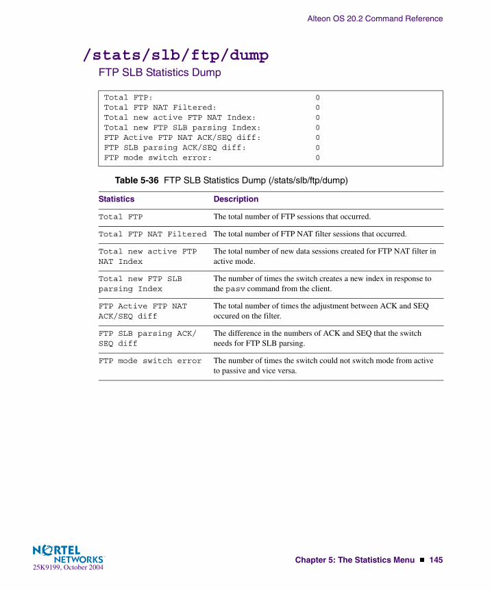
Alteon OS 20.2 Command Reference
Chapter 5: The Statistics Menu � 14525K9199, October 2004
/stats/slb/ftp/dumpFTP SLB Statistics Dump
Total FTP: 0Total FTP NAT Filtered: 0Total new active FTP NAT Index: 0Total new FTP SLB parsing Index: 0FTP Active FTP NAT ACK/SEQ diff: 0FTP SLB parsing ACK/SEQ diff: 0FTP mode switch error: 0
Table 5-36 FTP SLB Statistics Dump (/stats/slb/ftp/dump)
Statistics Description
Total FTP The total number of FTP sessions that occurred.
Total FTP NAT Filtered The total number of FTP NAT filter sessions that occurred.
Total new active FTP NAT Index
The total number of new data sessions created for FTP NAT filter in active mode.
Total new FTP SLB parsing Index
The number of times the switch creates a new index in response to the pasv command from the client.
FTP Active FTP NAT ACK/SEQ diff
The total number of times the adjustment between ACK and SEQ occured on the filter.
FTP SLB parsing ACK/SEQ diff
The difference in the numbers of ACK and SEQ that the switch needs for FTP SLB parsing.
FTP mode switch error The number of times the switch could not switch mode from active to passive and vice versa.
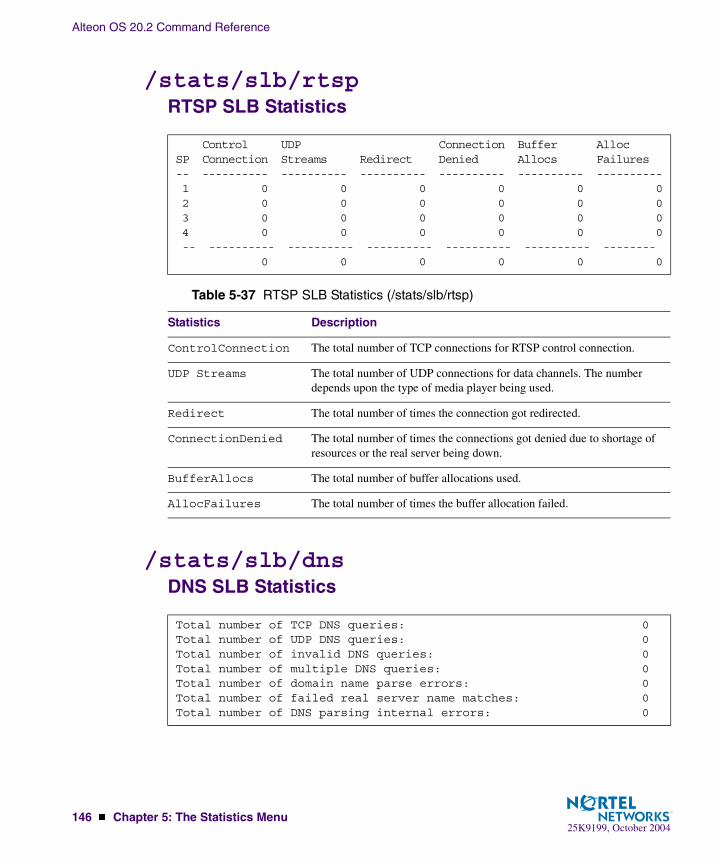
Alteon OS 20.2 Command Reference
146 � Chapter 5: The Statistics Menu25K9199, October 2004
/stats/slb/rtspRTSP SLB Statistics
/stats/slb/dnsDNS SLB Statistics
Control UDP Connection Buffer AllocSP Connection Streams Redirect Denied Allocs Failures-- ---------- ---------- ---------- ---------- ---------- ---------- 1 0 0 0 0 0 0 2 0 0 0 0 0 0 3 0 0 0 0 0 0 4 0 0 0 0 0 0 -- ---------- ---------- ---------- ---------- ---------- -------- 0 0 0 0 0 0
Table 5-37 RTSP SLB Statistics (/stats/slb/rtsp)
Statistics Description
ControlConnection The total number of TCP connections for RTSP control connection.
UDP Streams The total number of UDP connections for data channels. The number depends upon the type of media player being used.
Redirect The total number of times the connection got redirected.
ConnectionDenied The total number of times the connections got denied due to shortage of resources or the real server being down.
BufferAllocs The total number of buffer allocations used.
AllocFailures The total number of times the buffer allocation failed.
Total number of TCP DNS queries: 0Total number of UDP DNS queries: 0Total number of invalid DNS queries: 0Total number of multiple DNS queries: 0Total number of domain name parse errors: 0Total number of failed real server name matches: 0Total number of DNS parsing internal errors: 0
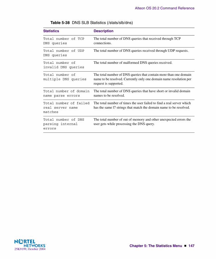
Alteon OS 20.2 Command Reference
Chapter 5: The Statistics Menu � 14725K9199, October 2004
Table 5-38 DNS SLB Statistics (/stats/slb/dns)
Statistics Description
Total number of TCP DNS queries
The total number of DNS queries that received through TCP connections.
Total number of UDP DNS queries
The total number of DNS queries received through UDP requests.
Total number of invalid DNS queries
The total number of malformed DNS queries received.
Total number of multiple DNS queries
The total number of DNS queries that contain more than one domain name to be resolved. Currently only one domain name resolution per request is supported.
Total number of domain name parse errors
The total number of DNS queries that have short or invalid domain names to be resolved.
Total number of failed real server name matches
The total number of times the user failed to find a real server which has the same l7 strings that match the domain name to be resolved.
Total number of DNS parsing internal errors
The total number of out of memory and other unexpected errors the user gets while processing the DNS query.

Alteon OS 20.2 Command Reference
148 � Chapter 5: The Statistics Menu25K9199, October 2004
/stats/slb/wapWAP SLB Statistics
WAP Maintenance stats: current sessions: 0 allocation failures: 0 incorrect VIPs: 0 incorrect Vports: 0 no available real server: 0 requests to wrong SP: 0------------------------------------------------------------------TPCP External Notification stats: add session reqs: 0 del session reqs: 0 req fails- q full: 0 req fails- q full: 0 req fails- SP dead: 0 req fails- SP dead: 0 entries in use: 0 entries in use: 0 max entries in use: 0 max entries in use: 0------------------------------------------------------------------RADIUS Snooping stats: acct reqs: 0 acct wrap reqs: 0 acct start reqs: 0 acct update reqs: 0 acct stop reqs: 0 acct bad reqs: 0 add session reqs: 0 del session reqs: 0 req fails- q full: 0 req fails- SP dead: 0 req fails- DMA: 0 max entries in use: 0
Table 5-39 WAP SLB Statistics (/stats/slb/wap)
Statistics Description
WAP Maintenance stats:
current sessions The number of session bindings currently in use.
allocation failures Indicates instances where the switch ran out of available bindings for a port.
incorrect VIPs Indicates the number of times the switch received a Layer 4 request for a virtual server which was not configured.
incorrect Vports This dropped frames counter indicates that the virtual server has received frames for TCP/UDP services that have not been configured. Normally this indicates a mis-configuration on the virtual server or the client.
no available real server
This dropped frames counter indicates that all real servers are either out of service or at their maxcon limit.
requests to wrong SP The number of session add/delete requests sent to the wrong SP.

Alteon OS 20.2 Command Reference
Chapter 5: The Statistics Menu � 14925K9199, October 2004
TPCP External Notification stats:
add session reqs The number of WAP session add requests via TPCP.
del session reqs The number of WAP session delete requests via TPCP.
req fails- q full The number of add-request failures due to request queue being full.
req fails- SP dead The number of add-request failures due to dead target SP.
entries in use The number of queue entries in use.
max entries in use The maximum number of queue entries in use at one time for session delete requests via TPCP.
RADIUS Snooping stats:
acct reqs The number of RADIUS Accounting frames received.
acct wrap reqs The number of wrapped RADIUS Accounting frames received.
acct start reqs The number of RADIUS Accounting Start frames received.
acct update reqs The number of RADIUS Accounting Update frames.
acct stop reqs The number of RADIUS Accounting Stop frames received.
acct bad reqs The number of bad RADIUS Accounting frames received.
add session reqs The number of WAP session add requests via RADIUS snooping.
del session reqs The number of WAP session delete requests via RADIUS snooping.
req fails- q full The number of add/delete requests failed due to request queue being full.
req fails- SP dead The number of add/delete request failures due to dead target SP.
req fails- DMA The number of add/delete requests failed due to DMA write failure.
max entries in use The maximum number of queue entries in use at a time for session add/delete requests via RADIUS snooping.
Table 5-39 WAP SLB Statistics (/stats/slb/wap)
Statistics Description

Alteon OS 20.2 Command Reference
150 � Chapter 5: The Statistics Menu25K9199, October 2004
/stats/slb/tcpSLB TCP Rate Limiting Statistics
/stats/slb/maintSLB Maintenance Statistics
TCP rate limiting stats: Total hold downs triggered: 0 Current per-client state entries: 0
Table 5-40 SLB TCP Rate Limiting Statistics (/stats/slb/tcp)
Statistics Description
Total hold downs triggered
The total number of hold downs that occurred since the last stats clear.
Current per-client state entries
The current number of per client state entries in the session table.
SLB Maintenance stats:Maximum sessions: 2093056Current sessions: 0 4 second average: 0 64 second average: 0Terminated sessions: 0Allocation failures: 0TCP fragments: 0UDP datagrams: 0Non TCP/IP frames: 0Incorrect VIPs: 0Incorrect Vports: 0No available real server: 0Backup server activations: 0Overflow server activations: 0Filtered (denied) frames: 0LAND attacks: 0Total IP fragment sessions: 0Current IP fragment sessions 0IP fragment discards: 0IP fragment table full: 0
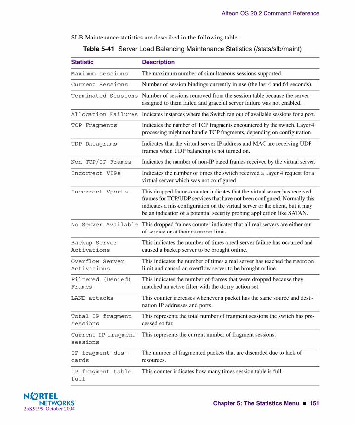
Alteon OS 20.2 Command Reference
Chapter 5: The Statistics Menu � 15125K9199, October 2004
SLB Maintenance statistics are described in the following table.
Table 5-41 Server Load Balancing Maintenance Statistics (/stats/slb/maint)
Statistic Description
Maximum sessions The maximum number of simultaneous sessions supported.
Current Sessions Number of session bindings currently in use (the last 4 and 64 seconds).
Terminated Sessions Number of sessions removed from the session table because the server assigned to them failed and graceful server failure was not enabled.
Allocation Failures Indicates instances where the Switch ran out of available sessions for a port.
TCP Fragments Indicates the number of TCP fragments encountered by the switch. Layer 4 processing might not handle TCP fragments, depending on configuration.
UDP Datagrams Indicates that the virtual server IP address and MAC are receiving UDP frames when UDP balancing is not turned on.
Non TCP/IP Frames Indicates the number of non-IP based frames received by the virtual server.
Incorrect VIPs Indicates the number of times the switch received a Layer 4 request for a virtual server which was not configured.
Incorrect Vports This dropped frames counter indicates that the virtual server has received frames for TCP/UDP services that have not been configured. Normally this indicates a mis-configuration on the virtual server or the client, but it may be an indication of a potential security probing application like SATAN.
No Server Available This dropped frames counter indicates that all real servers are either out of service or at their maxcon limit.
Backup Server Activations
This indicates the number of times a real server failure has occurred and caused a backup server to be brought online.
Overflow Server Activations
This indicates the number of times a real server has reached the maxcon limit and caused an overflow server to be brought online.
Filtered (Denied) Frames
This indicates the number of frames that were dropped because they matched an active filter with the deny action set.
LAND attacks This counter increases whenever a packet has the same source and desti-nation IP addresses and ports.
Total IP fragment sessions
This represents the total number of fragment sessions the switch has pro-cessed so far.
Current IP fragment sessions
This represents the current number of fragment sessions.
IP fragment dis-cards
The number of fragmented packets that are discarded due to lack of resources.
IP fragment table full
This counter indicates how many times session table is full.

Alteon OS 20.2 Command Reference
152 � Chapter 5: The Statistics Menu25K9199, October 2004
/stats/slb/clearClearing the SLB StatisticsThe following statistics are reset to zero when the clear command is given and confirmed:
Table 5-42 SLB Statistics Reset (/stats/slb/clear)
Statistics Description
Real server stats: Health check failuresTotal sessionsHighest sessionsOctets
Real server group stats:
Total sessionsHighest sessionsOctets
Virtual server stats
Total sessionsHighest sessionsOctets
Filter stats Total firings
SLB switch port stats, per port
Real server stats: Octets, Total sessionsReal server group: Octets, Total sessionsVirtual server: Octets, Total sessionsTotal firings: Octets
Global SLB stats Per real server:DNS handoffsHTTP redirects
Per server group:DNS handoffsHTTP redirects
URL SLB and Redi-rection stats
Redir:Total cache server hitsTotal origin server hitsTotal none-GETs hitsTotal ’Cookie: ’ hitsTotal no-cache hits
LB:ID SLB String hits
SSL SLB stats Total SessionsHighest Sessions

Alteon OS 20.2 Command Reference
Chapter 5: The Statistics Menu � 15325K9199, October 2004
/stats/mpManagement Processor Statistics
FTP SLB parsing and NAT stats
Total FTPTotal FTP NAT FilteredTotal new active FTP NAT IndexTotal new FTP SLB parsing IndexFTP Active FTP NAT ACK/SEQ diffFTP SLB parsing ACK/SEQ diff
Real server stats Health check failuresTotal sessionsHighest sessionsOctets
Real server group stats
Total sessionsHighest sessionsOctets
Virtual server stats
Total sessionsHighest sessionsOctets
[MP-specific Statistics Menu] pkt - Show Packet stats tcb - Show All TCP control blocks in use ucb - Show All UDP control blocks in use cpu - Show CPU utilization mem - Show memory stats
Table 5-43 Management Processor Statistics Menu Options (/stats/mp)
Command Syntax and Usage
pkt
Displays packet statistics, to check for leads and load. To view a sample output and a description of the stats, see page 154.
tcb
Displays all TCP control blocks that are in use. To view a sample output and a description of the stats, see page 155.
Table 5-42 SLB Statistics Reset (/stats/slb/clear)
Statistics Description

Alteon OS 20.2 Command Reference
154 � Chapter 5: The Statistics Menu25K9199, October 2004
/stats/mp/pktMP Packet Statistics
ucb
Displays all UDP control blocks that are in use. To view a sample output, see page 155.
sfd
Displays all Socket File Descriptors that are in use. To view a sample output, see page 156.
cpu
Displays CPU utilization for periods of up to 1, 4, and 64 seconds. To view a sample output and a description of the stats, see page 156.
mem
Displays memory statistics.
Packet counts: allocs: 1166996 frees: 1166996 mediums: 0 mediums hi-watermark: 7 smalls: 0 smalls hi-watermark: 7 failures: 0
Table 5-44 Packet Statistics (/stats/mp/pkt)
Statistics Description
allocs Total number of packet allocations from the packet buffer pool by the TCP/IP protocol stack.
frees Total number of times the packet buffers are freed (released) to the packet buffer pool by the TCP/IP protocol stack.
mediums Total number of packet allocations with size between 128 to 1536 bytes from the packet buffer pool by the TCP/IP protocol stack.
smalls Total number of packet allocations with size less than 128 bytes from the packet buffer pool by the TCP/IP protocol stack.
failures Total number of packet allocation failures from the packet buffer pool by the TCP/IP protocol stack.
frees Total number of packets freed from the packet buffer pool by the TCP/IP protocol stack.
Table 5-43 Management Processor Statistics Menu Options (/stats/mp)
Command Syntax and Usage
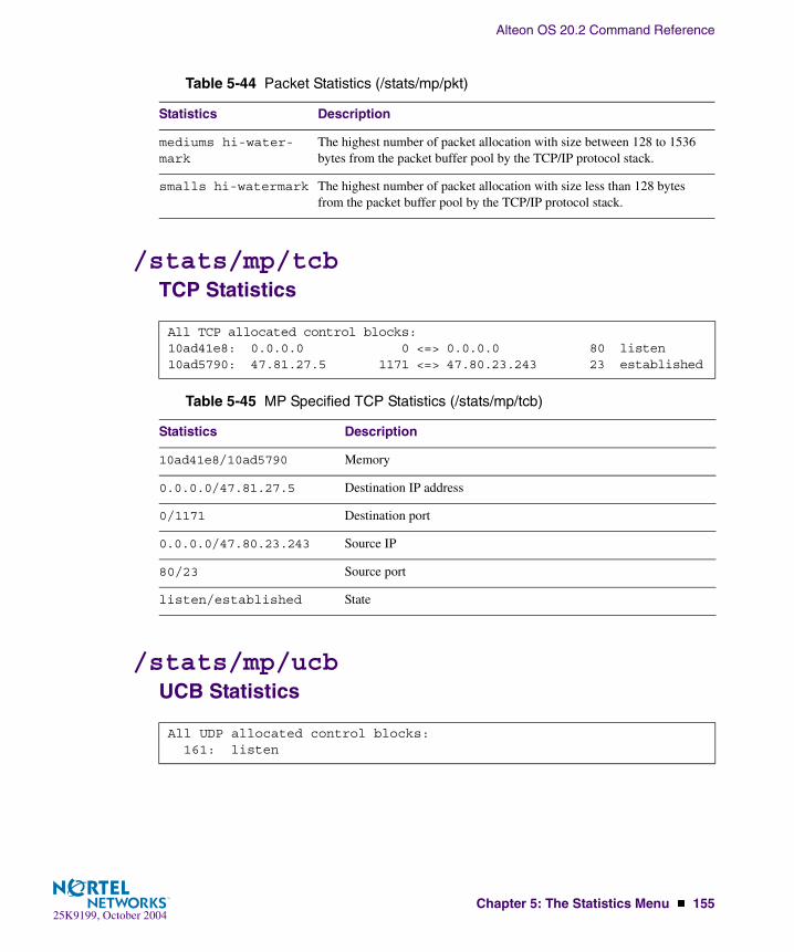
Alteon OS 20.2 Command Reference
Chapter 5: The Statistics Menu � 15525K9199, October 2004
/stats/mp/tcbTCP Statistics
/stats/mp/ucbUCB Statistics
mediums hi-water-mark
The highest number of packet allocation with size between 128 to 1536 bytes from the packet buffer pool by the TCP/IP protocol stack.
smalls hi-watermark The highest number of packet allocation with size less than 128 bytes from the packet buffer pool by the TCP/IP protocol stack.
All TCP allocated control blocks:10ad41e8: 0.0.0.0 0 <=> 0.0.0.0 80 listen10ad5790: 47.81.27.5 1171 <=> 47.80.23.243 23 established
Table 5-45 MP Specified TCP Statistics (/stats/mp/tcb)
Statistics Description
10ad41e8/10ad5790 Memory
0.0.0.0/47.81.27.5 Destination IP address
0/1171 Destination port
0.0.0.0/47.80.23.243 Source IP
80/23 Source port
listen/established State
All UDP allocated control blocks: 161: listen
Table 5-44 Packet Statistics (/stats/mp/pkt)
Statistics Description

Alteon OS 20.2 Command Reference
156 � Chapter 5: The Statistics Menu25K9199, October 2004
/stats/mp/sfdMP-Specific SFD Statistics
/stats/mp/cpuCPU StatisticsThis menu option enables you to display the CPU utilization statistics.
/stats/sp <SP Number>SP Specific Statistics Menu
All Socket FD allocated:max_fdi=2 fdi=0 fd=15 pfdi=-110c27fd8: 0.0.0.0 0<=>47.133.108.161 80 listen TCP serverfdi=1 fd=16 pfdi=-110b9564c: 0.0.0.0 0<=>47.133.108.161 23 listen TCP serverfdi=2 fd=17 pfdi=110c27c78: 47.129.153.150 5341<=>47.133.108.161 23 accept TCP server
CPU utilization:cpuUtil1Second: 53%cpuUtil4Seconds: 54%cpuUtil64Seconds: 54%
Table 5-46 CPU Statistics (stats/mp/cpu)
Statistics Description
cpuUtil1Second The utilization of MP CPU over 1 second. It shows the percentage.
cpuUtil4Seconds The utilization of MP CPU over 4 seconds. It shows the percentage.
cpuUtil64Seconds The utilization of MP CPU over 64 seconds. It shows the percentage.
[SP-specific Statistics Menu] maint - Show maintenance stats clear - Clear maintenance stats cpu - Show CPU utilization

Alteon OS 20.2 Command Reference
Chapter 5: The Statistics Menu � 15725K9199, October 2004
/stats/pacePacket Acceleration Statistics Menu
Table 5-47 SP Specific Statistics (/stats/sp)
Statistics Description
maint Indicates the total number of all the letter statistics received or sent from this SP.
clear Deletes all the maintenance statistics.
cpu Displays what percentage of the CPU has been utilized.
[Packet Acceleration Statistics Menu] error - PACE Error Stats info - PACE Informational Stats maint - PACE Maintenance Stats fp - PACE HFP Stats clear - Clear non-operational PACE stats dump - Dump all PACE statistics
Table 5-48 Packet Acceleration Statistics (/stats/pace)
Statistics Description
error Display error statistics on the PACE processor.
info Display general information about PACE performance.
maint Display session data about the utilzation of PACE resources.
fp Display hardware counts for data passed through the frame processor.
clear Clear non-operational PACE statistics.
dump Dump all PACE statistics.

Alteon OS 20.2 Command Reference
158 � Chapter 5: The Statistics Menu25K9199, October 2004
/stats/snmpSNMP Statistics
SNMP statistics:snmpInPkts: 54 snmpInBadVersions: 0snmpInBadC’tyNames: 0 snmpInBadC’tyUses: 0snmpInASNParseErrs: 0 snmpEnableAuthTraps: 0snmpOutPkts: 54 snmpInBadTypes: 0snmpInTooBigs: 0 snmpInNoSuchNames: 0snmpInBadValues: 0 snmpInReadOnlys: 0snmpInGenErrs: 0 snmpInTotalReqVars: 105snmpInTotalSetVars: 0 snmpInGetRequests: 2snmpInGetNexts: 52 snmpInSetRequests: 0snmpInGetResponses: 0 snmpInTraps: 0snmpOutTooBigs: 0 snmpOutNoSuchNames: 2snmpOutBadValues: 0 snmpOutReadOnlys: 0snmpOutGenErrs: 0 snmpOutGetRequests: 0snmpOutGetNexts: 0 snmpOutSetRequests: 0snmpOutGetResponses: 54 snmpOutTraps: 0
Table 5-49 SNMP Statistics (/stats/snmp)
Statistics Description
snmpInPkts The total number of Messages delivered to the SNMP entity from the transport service.
snmpInBadVersions The total number of SNMP Messages, which were delivered to the SNMP protocol entity and were for an unsupported SNMP version.
snmpInBadC’tyNames The total number of SNMP Messages delivered to the SNMP entity which used an SNMP community name not known to the said entity (the switch).
snmpInBadC’tyUses The total number of SNMP Messages delivered to the SNMP protocol entity which represented an SNMP operation which was not allowed by the SNMP community named in the Message.
snmpInASNParseErrs The total number of ASN.1 or BER errors encountered by the SNMP pro-tocol entity when decoding SNMP Messages received.Note: OSI’s method of specifying abstract objects is called ASN.1 (Abstract Syntax Notation One, defined in X.208), and one set of rules for representing such objects as strings of ones and zeros is called the BER (Basic Encoding Rules, defined in X.209). ASN.1 is a flexible nota-tion that allows one to define a variety of data types, from simple types such as integers and bit strings to structured types such as sets and sequences. BER describes how to represent or encode values of each ASN.1 type as a string of eight-bit octets.

Alteon OS 20.2 Command Reference
Chapter 5: The Statistics Menu � 15925K9199, October 2004
snmpEnableAuthTraps
An object to enable or disable the authentication traps generated by this entity (the switch).
snmpOutPkts The total number of SNMP Messages which were passed from the SNMP protocol entity to the transport service.
snmpInBadTypes The total number of SNMP Messages which failed ASN parsing.
snmpInTooBigs The total number of SNMP Protocol Data Units (PDUs) which were delivered to the SNMP protocol entity and for which the value of the error-status field is too big.
snmpInNoSuchNames The total number of SNMP Protocol Data Units (PDUs) which were delivered to the SNMP protocol entity and for which the value of the error-status field is noSuchName.
snmpInBadValues The total number of SNMP Protocol Data Units (PDUs) which were delivered to the SNMP protocol entity and for which the value of the error-status field is badValue.
snmpInReadOnlys The total number of valid SNMP Protocol Data Units (PDUs), which were delivered to the SNMP protocol entity and for which the value of the error-status field is ‘read-Only’. It should be noted that it is a protocol error to generate an SNMP PDU, which contains the value ‘read-Only’ in the error-status field. As such, this object is provided as a means of detecting incorrect implementations of the SNMP.
snmpInGenErrs The total number of SNMP Protocol Data Units (PDUs), which were delivered to the SNMP protocol entity and for which the value of the error-status field is genErr.
snmpInTotalReqVars The total number of MIB objects which have been retrieved successfully by the SNMP protocol entity as a result of receiving valid SNMP Get-Request and Get-Next Protocol Data Units (PDUs).
snmpInTotalSetVars The total number of MIB objects, which have been altered successfully by the SNMP protocol entity as a result of receiving valid SNMP Set-Request Protocol Data Units (PDUs).
snmpInGetRequests The total number of SNMP Get-Request Protocol Data Units (PDUs), which have been accepted and processed by the SNMP protocol entity.
snmpInGetNexts The total number of SNMP Get-Next Protocol Data Units (PDUs), which have been accepted and processed by the SNMP protocol entity.
snmpInSetRequests The total number of SNMP Set-Request Protocol Data Units (PDUs), which have been accepted and processed by the SNMP protocol entity.
Table 5-49 SNMP Statistics (/stats/snmp)
Statistics Description
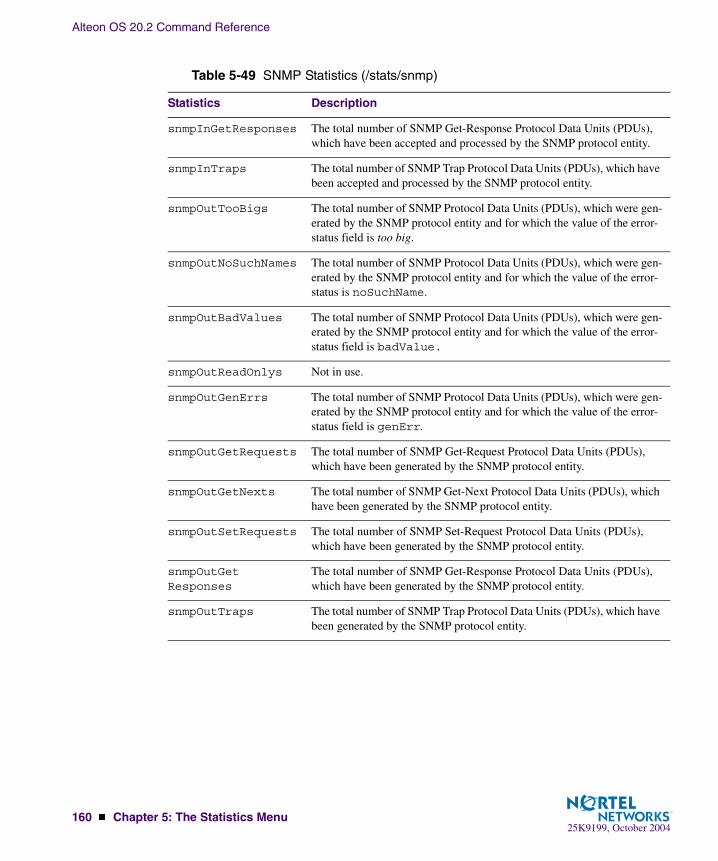
Alteon OS 20.2 Command Reference
160 � Chapter 5: The Statistics Menu25K9199, October 2004
snmpInGetResponses The total number of SNMP Get-Response Protocol Data Units (PDUs), which have been accepted and processed by the SNMP protocol entity.
snmpInTraps The total number of SNMP Trap Protocol Data Units (PDUs), which have been accepted and processed by the SNMP protocol entity.
snmpOutTooBigs The total number of SNMP Protocol Data Units (PDUs), which were gen-erated by the SNMP protocol entity and for which the value of the error-status field is too big.
snmpOutNoSuchNames The total number of SNMP Protocol Data Units (PDUs), which were gen-erated by the SNMP protocol entity and for which the value of the error-status is noSuchName.
snmpOutBadValues The total number of SNMP Protocol Data Units (PDUs), which were gen-erated by the SNMP protocol entity and for which the value of the error-status field is badValue.
snmpOutReadOnlys Not in use.
snmpOutGenErrs The total number of SNMP Protocol Data Units (PDUs), which were gen-erated by the SNMP protocol entity and for which the value of the error-status field is genErr.
snmpOutGetRequests The total number of SNMP Get-Request Protocol Data Units (PDUs), which have been generated by the SNMP protocol entity.
snmpOutGetNexts The total number of SNMP Get-Next Protocol Data Units (PDUs), which have been generated by the SNMP protocol entity.
snmpOutSetRequests The total number of SNMP Set-Request Protocol Data Units (PDUs), which have been generated by the SNMP protocol entity.
snmpOutGetResponses
The total number of SNMP Get-Response Protocol Data Units (PDUs), which have been generated by the SNMP protocol entity.
snmpOutTraps The total number of SNMP Trap Protocol Data Units (PDUs), which have been generated by the SNMP protocol entity.
Table 5-49 SNMP Statistics (/stats/snmp)
Statistics Description

Alteon OS 20.2 Command Reference
Chapter 5: The Statistics Menu � 16125K9199, October 2004
/stats/ntpNTP Statistics
Alteon OS uses NTP (Network Timing Protocol) version 3 to synchronize the switch’s internal clock with an atomic time calibrated NTP server. With NTP enabled, the switch can accurately update its internal clock to be consistent with other devices on the network and generates accu-rate syslogs. NTP statistics: Primary Server: Requests Sent: 17 Responses Received: 17 Updates: 1 Secondary Server: Requests Sent: 0 Responses Received: 0 Updates: 0
Table 5-50 NTP Statistics Parameters (/stats/ntp)
Field Description
Primary Server Requests Sent: The total number of NTP requests the switch sent tothe primary NTP server to synchronize time.
Responses Received: The total number of NTP responses receivedfrom the primary NTP server.
Updates: The total number of times the switch updated its timebased on the NTP responses received from the primary NTP server.
Secondary Server Requests Sent: The total number of NTP requests the switch sent tothe secondary NTP server to synchronize time.
Responses Received: The total number of NTP responses receivedfrom the secondary NTP server.
Updates: The total number of times the switch updated its timebased on the NTP responses received from the secondary NTPserver.

Alteon OS 20.2 Command Reference
162 � Chapter 5: The Statistics Menu25K9199, October 2004
/stats/dumpStatistics Dump
Use the dump command to dump all switch statistics available from the Statistics Menu (40K or more,
depending on your configuration). This data can be used to tune or debug switch performance.
If you want to capture dump data to a file, set your communication software on your worksta-tion to capture session data prior to issuing the dump commands.

25K9199, October 2004163
CHAPTER 6The Configuration Menu
This chapter discusses how to use the Command Line Interface (CLI) for making, viewing, and saving switch configuration changes. Many of the commands, although not new, display more or different information than in the previous version. Important differences are called out in the text.
To make finding information easier, the menu options under the Server Load Balancing Menu (/cfg/slb) are in Chapter 7.
/cfgConfiguration Menu
[Configuration Menu] sys - System-wide Parameter Menu port - Port Menu pmirr - Port Mirroring Menu l2 - Layer 2 Menu l3 - Layer 3 Menu slb - Server Load Balancing (Layer 4-7) Menu setup - Step by step configuration set up dump - Dump current configuration to script file ptcfg - Backup current configuration to tftp server gtcfg - Restore current configuration from tftp server
Table 6-1 Configuration Menu Options (/cfg)
Command Syntax and Usage
sys
Displays the System Configuration Menu. To view menu options, see page 167.
port <port alias or number>Displays the Port Configuration Menu. To view menu options, see page 181.

Alteon OS 20.2 Command Reference
164 � Chapter 6: The Configuration Menu25K9199, October 2004
Viewing, Applying, and Saving Changes
As you use the configuration menus to set switch parameters, the changes you make do not take effect immediately. All changes are considered “pending” until you explicitly apply them. Also, any changes are lost the next time the switch boots unless the changes are explicitly saved.
NOTE – Some operations can override the settings in the Configuration menu. Therefore, set-tings you view in the Configuration menu (for example, port status) might differ from run-time information that you view in the Information menu or on the management module. The Infor-mation menu displays current run-time information of switch parameters.
pmirr
Displays the Mirroring Configuration Menu. To view menu options, see page 184.
l2
Displays the Layer 2 Configuration Menu. To view menu options, see page 186.
l3
Displays the Layer 3 Configuration Menu. To view menu options, see page 200.
slb
Displays the Server Load Balancing Configuration Menu. To view menu options, see Chapter 7, “The SLB Configuration Menu”.
setup
Step-by-step configuration set-up of the switch. For details, see page 249.
dump
Dumps current configuration to a script file. For details, see page 249.
ptcfg <host name or IP address of TFTP server> <filename on host>Backs up current configuration to TFTP server. For details, see page 250.
gtcfg <host name or IP address of TFTP server> <filename on host>Restores current configuration from TFTP server. For details, see page 250.
Table 6-1 Configuration Menu Options (/cfg)
Command Syntax and Usage

Alteon OS 20.2 Command Reference
Chapter 6: The Configuration Menu � 16525K9199, October 2004
While configuration changes are in the pending state, you can do the following:
� View the pending changes
� Apply the pending changes
� Save the changes to flash memory
Viewing Pending ChangesYou can view all pending configuration changes by entering diff at the menu prompt.
NOTE – The diff command is a global command. Therefore, you can enter diff at any prompt in the CLI.
Applying Pending ChangesTo make your configuration changes active, you must apply them. To apply configuration changes, enter apply at any prompt in the CLI.
NOTE – The apply command is a global command. Therefore, you can enter apply at any prompt in the administrative interface.
NOTE – All configuration changes take effect immediately when applied, except for starting Spanning Tree Group. To turn STG on or off, you must apply the changes, save them (see below), and then reset the switch (see “Resetting the Switch” on page 310).
Saving the ConfigurationIn addition to applying the configuration changes, you can save them to flash memory on the GbE Switch Module.
NOTE – If you do not save the changes, they will be lost the next time the system is rebooted.
To save the new configuration, enter the following command at any CLI prompt:
# apply
# save

Alteon OS 20.2 Command Reference
166 � Chapter 6: The Configuration Menu25K9199, October 2004
When you save configuration changes, the changes are saved to the active configuration block. The configuration being replaced by the save is first copied to the backup configuration block. If you do not want the previous configuration block copied to the backup configuration block, enter the following instead:
You can decide which configuration you want to run the next time you reset the switch. Your options include:
� The active configuration block
� The backup configuration block
� Factory default configuration
You can view all pending configuration changes that have been applied but not saved to flash memory using the diff flash command. It is a global command that can be executed from any menu.
For instructions on selecting the configuration to run at the next system reset, see “Selecting a Configuration Block” on page 309.
# save n
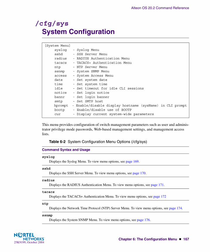
Alteon OS 20.2 Command Reference
Chapter 6: The Configuration Menu � 16725K9199, October 2004
/cfg/sysSystem Configuration
This menu provides configuration of switch management parameters such as user and adminis-trator privilege mode passwords, Web-based management settings, and management access lists.
[System Menu] syslog - Syslog Menu sshd - SSH Server Menu radius - RADIUS Authentication Menu tacacs - TACACS+ Authentication Menu ntp - NTP Server Menu ssnmp - System SNMP Menu access - System Access Menu date - Set system date time - Set system time idle - Set timeout for idle CLI sessions notice - Set login notice bannr - Set login banner smtp - Set SMTP host hprompt - Enable/disable display hostname (sysName) in CLI prompt bootp - Enable/disable use of BOOTP cur - Display current system-wide parameters
Table 6-2 System Configuration Menu Options (/cfg/sys)
Command Syntax and Usage
syslog
Displays the Syslog Menu. To view menu options, see page 169.
sshd
Displays the SSH Server Menu. To view menu options, see page 170.
radius
Displays the RADIUS Authentication Menu. To view menu options, see page 171.
tacacs
Displays the TACACS+ Authentication Menu. To view menu options, see page 172
ntp
Displays the Network Time Protocol (NTP) Server Menu. To view menu options, see page 174.
ssnmp
Displays the System SNMP Menu. To view menu options, see page 176.

Alteon OS 20.2 Command Reference
168 � Chapter 6: The Configuration Menu25K9199, October 2004
access
Displays the System Access Menu. To view menu options, see page 178.
date
Prompts the user for the system date. The date reverts to its default value when the switch is reset.
time
Configures the system time using a 24-hour clock format. The time reverts to its default value when the switch is reset.
idle <idle timeout in minutes Telnet>Sets the idle timeout for CLI sessions, from 1 to 60 minutes. The default is 5 minutes.
notice <max 1024 char multi-line login notice> <’-’ to end>Displays login notice immediately before the “Enter password:” prompt. This notice can contain up to 1024 characters and new lines.
bannr <string, maximum 80 characters>Configures a login banner of up to 80 characters. When a user or administrator logs into the switch, the login banner is displayed. It is also displayed as part of the output from the /info/sys com-mand.
smtp <SMTP host name or IP address>Sets the Simple Mail Transfer Protocol (SMTP) host, which is used for sending bandwidth man-agement history information.
hprompt disable|enable
Enables or disables displaying of the host name (system administrator’s name) in the Command Line Interface (CLI).
bootp disable|enable
Enables or disables the use of BOOTP. If you enable BOOTP, the switch will query its BOOTP server for all of the switch IP parameters. This command is disabled by default.
cur
Displays the current system parameters.
Table 6-2 System Configuration Menu Options (/cfg/sys)
Command Syntax and Usage
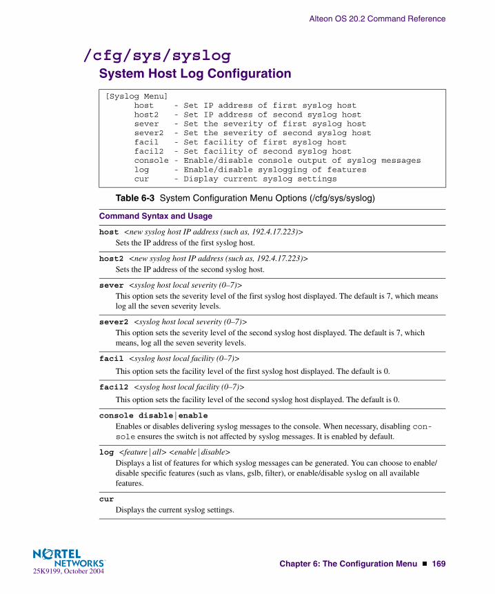
Alteon OS 20.2 Command Reference
Chapter 6: The Configuration Menu � 16925K9199, October 2004
/cfg/sys/syslogSystem Host Log Configuration
[Syslog Menu] host - Set IP address of first syslog host host2 - Set IP address of second syslog host sever - Set the severity of first syslog host sever2 - Set the severity of second syslog host facil - Set facility of first syslog host facil2 - Set facility of second syslog host console - Enable/disable console output of syslog messages log - Enable/disable syslogging of features cur - Display current syslog settings
Table 6-3 System Configuration Menu Options (/cfg/sys/syslog)
Command Syntax and Usage
host <new syslog host IP address (such as, 192.4.17.223)>Sets the IP address of the first syslog host.
host2 <new syslog host IP address (such as, 192.4.17.223)>Sets the IP address of the second syslog host.
sever <syslog host local severity (0–7)>This option sets the severity level of the first syslog host displayed. The default is 7, which means log all the seven severity levels.
sever2 <syslog host local severity (0–7)>This option sets the severity level of the second syslog host displayed. The default is 7, which means, log all the seven severity levels.
facil <syslog host local facility (0–7)>
This option sets the facility level of the first syslog host displayed. The default is 0.
facil2 <syslog host local facility (0–7)>
This option sets the facility level of the second syslog host displayed. The default is 0.
console disable|enable
Enables or disables delivering syslog messages to the console. When necessary, disabling con-sole ensures the switch is not affected by syslog messages. It is enabled by default.
log <feature|all> <enable|disable>Displays a list of features for which syslog messages can be generated. You can choose to enable/disable specific features (such as vlans, gslb, filter), or enable/disable syslog on all available features.
cur
Displays the current syslog settings.

Alteon OS 20.2 Command Reference
170 � Chapter 6: The Configuration Menu25K9199, October 2004
/cfg/sys/sshdSSH Server Configuration Menu
For the GbE Switch Module, this menu enables Secure Shell access from any SSH client. SSH scripts can be viewed by using the /cfg/dump command (see page 249).
NOTE – Except for cur, the commands of this menu are only accessible through the manage-ment module interface.
[SSHD Menu] intrval - Set Interval for generating the RSA server key scpadm - Set SCP-only admin password hkeygen - Generate the RSA host key skeygen - Generate the RSA server key sshport - Set SSH server port number ena - Enable the SCP apply and save dis - Disable the SCP apply and save on - Turn SSH server ON off - Turn SSH server OFF cur - Display current SSH server configuration
Table 6-4 System Configuration Menu Options (/cfg/sys/sshd)
Command Syntax and Usage
intrval <0 - 24>Set the interval for auto-generation of the RSA server key.
scpadm
Set the administration password for SCP access.
hkeygen
Generate the RSA host key.
skeygen
Generate the RSA server key.
sshport <TCP port number>Sets the SSH server port number.
ena
Enables the SCP apply and save.
dis
Disables the SCP apply and save.
on
Enables the SSH server.

Alteon OS 20.2 Command Reference
Chapter 6: The Configuration Menu � 17125K9199, October 2004
/cfg/sys/radiusRADIUS Server Configuration
offDisables the SSH server.
cur
Displays the current SSH server configuration.
[RADIUS Server Menu] prisrv - Set primary RADIUS server address secsrv - Set secondary RADIUS server address secret - Set RADIUS secret secret2 - Set secondary RADIUS server secret port - Set RADIUS port retries - Set RADIUS server retries timeout - Set RADIUS server timeout telnet - Enable or disable RADIUS backdoor for telnet on - Turn RADIUS authentication ON off - Turn RADIUS authentication OFF cur - Display current RADIUS configuration
Table 6-5 System Configuration Menu Options (/cfg/sys/radius)
Command Syntax and Usage
prisrv <IP address>Sets the primary RADIUS server address.
secsrv <IP address>Sets the secondary RADIUS server address.
secret <1-32 character secret>This is the shared secret between the switch and the RADIUS server(s).
secret2 <1-32 character secret>This is the secondary shared secret between the switch and the RADIUS server(s).
port <RADIUS port configure, default 1645>Enter the number of the UDP port to be configured, between 1500 - 3000. The default is 1645.
retries <RADIUS server retries (1-3)>Sets the number of failed authentication requests before switching to a different RADIUS server. The default is 3 requests.
Table 6-4 System Configuration Menu Options (/cfg/sys/sshd)
Command Syntax and Usage

Alteon OS 20.2 Command Reference
172 � Chapter 6: The Configuration Menu25K9199, October 2004
/cfg/sys/tacacs+TACACS+ Server Configuration MenuTACACS (Terminal Access Controller Access Control system) is an authentication protocol that allows a remote access server to forward a user’s logon password to an authentication server to determine whether access can be allowed to a given system. TACACS is an encryption protocol, and therefore less secure than TACACS+ and Remote Authentication Dial-In User Service (RADIUS) protocols. (Both TACACS and TACACS+ are described in RFC 1492.)
TACACS+ protocol is more reliable than RADIUS, as TACACS+ uses the Transmission Con-trol Protocol (TCP) whereas RADIUS uses the User Datagram Protocol (UDP). Also, RADIUS combines authentication and authorization in a user profile, whereas TACACS+ separates the two operations.
TACACS+ offers the following advantages over RADIUS as the authentication device:
� TACACS+ is TCP-based, so it facilitates connection-oriented traffic.
� It supports full-packet encryption, as opposed to password-only in authentication requests.
� It supports decoupled authentication, authorization, and accounting.
timeout <RADIUS server timeout seconds (1-10)>Sets the amount of time, in seconds, before a RADIUS server authentication attempt is considered to have failed. The default is 3 seconds.
telnet disable|enableEnables or disables the RADIUS backdoor for telnet. The telnet command also applies to SSH/SCP connections and the Browser-Based Interface (BBI). The default is disabled.
To obtain the RADIUS backdoor password for your GbESM, contact your IBM Service and Support line.
on
Enables the RADIUS server.
off
Disables the RADIUS server.
cur
Displays the current RADIUS server parameters.
Table 6-5 System Configuration Menu Options (/cfg/sys/radius)
Command Syntax and Usage

Alteon OS 20.2 Command Reference
Chapter 6: The Configuration Menu � 17325K9199, October 2004
[TACACS+ Server Menu] prisrv - Set primary TACACS+ server address secsrv - Set secondary TACACS+ server address secret - Set primary TACACS+ server secret secret2 - Set secondary TACACS+ server secret port - Set TACACS+ TCP port retries - Set TACACS+ server retries timeout - Set TACACS+ server timeout (seconds) telnet - Enable/disable TACACS+ backdoor for telnet cauth - Enable/disable TACACS+ command authorization clog - Enable/disable TACACS+ command logging on - Turn TACACS+ authentication ON off - Turn TACACS+ authentication OFF cur - Display current TACACS+ configuration
Table 6-6 TACACS+ Server Menu Options (/cfg/sys/tacacs)
Command Syntax and Usage
prisrv <IP address>Defines the primary TACACS+ server address.
secsrv <IP address>Defines the secondary TACACS+ server address.
secret <1-32 character secret>This is the shared secret between the switch and the TACACS+ server(s).
secret2 <1-32 character secret>This is the secondary shared secret between the switch and the TACACS+ server(s).
port <TACACS port configure, default 49>Enter the number of the TCP port to be configured, between 1 - 65000. The default is 49.
retries <TACACS server retries, 1-3>Sets the number of failed authentication requests before switching to a different TACACS+ server. The default is 3 requests.
timeout <TACACS server timeout seconds, 4-15>Sets the amount of time, in seconds, before a TACACS+ server authentication attempt is consid-ered to have failed. The default is 5 seconds.
telnet disable|enable
Enables or disables the TACACS+ back door for telnet. The telnet command also applies to SSH/SCP connections, and the Browser-Based Interface (BBI). The default is disabled.
To obtain the TACACS+ backdoor password for your GbESM, contact your IBM Service and Support line.

Alteon OS 20.2 Command Reference
174 � Chapter 6: The Configuration Menu25K9199, October 2004
/cfg/sys/ntpNTP Server Configuration
cauth disable|enable
Enables or disables TACACS+ command authorization.
clog disable|enable
Enables or disables TACACS+ command logging.
on
Enables the TACACS+ server. This is the default setting.
off
Disables the TACACS+ server.
cur
Displays current TACACS+ configuration parameters.
[NTP Server Menu] prisrv - Set primary NTP server address secsrv - Set secondary NTP server address intrval - Set NTP server resync interval tzone - Set NTP timezone offset from GMT dlight - Enable or disable NTP daylight savings time on - Turn NTP service ON off - Turn NTP service OFF cur - Display current NTP configuration
Table 6-6 TACACS+ Server Menu Options (/cfg/sys/tacacs)
Command Syntax and Usage

Alteon OS 20.2 Command Reference
Chapter 6: The Configuration Menu � 17525K9199, October 2004
This menu enables you to synchronize the switch clock to a Network Time Protocol (NTP) server. By default, this option is disabled.
Table 6-7 System Configuration Menu Options (/cfg/sys/ntp)
Command Syntax and Usage
prisrv <NTP Server IP address>Prompts for the IP addresses of the primary NTP server to which you want to synchronize the switch clock.
secsrv <NTP Server IP address>Prompts for the IP addresses of the secondary NTP server to which you want to synchronize the switch clock.
intrval <resync interval in minutes>Specifies the interval, that is, how often, in minutes (1-2880), to re-synchronize the switch clock with the NTP server.
tzone <timezone offset, in HH:MM>Prompts for the NTP time zone offset, in hours and minutes, of the switch you are synchronizing from Greenwich Mean Time (GMT).
dlight disable|enable
Disables or enables daylight savings time in the system clock. When enabled, the switch will add an extra hour to the system clock so that it is consistent with the local clock. By default, this option is disabled.
on Enables the NTP synchronization service.
off
Disables the NTP synchronization service.
cur
Displays the current NTP service settings.

Alteon OS 20.2 Command Reference
176 � Chapter 6: The Configuration Menu25K9199, October 2004
cfg/sys/ssnmpSystem SNMP Menu
The Alteon OS software supports SNMP-based network management. If you are running an SNMP network management station on your network, you can manage the switch using the following standard SNMP MIBs:
� MIB II (RFC 1213)
� Ethernet MIB (RFC 1643)
� Bridge MIB (RFC 1493)
[System SNMP Menu] name - Set SNMP "sysName" locn - Set SNMP "sysLocation" cont - Set SNMP "sysContact" rcomm - Set SNMP read community string wcomm - Set SNMP write community string trap1 - Set first SNMP trap host address trap2 - Set second SNMP trap host address t1comm - Set community string for first trap host t2comm - Set community string for second trap host timeout - Set timeout for the SNMP state machine auth - Enable/disable SNMP "sysAuthenTrap" linkt - Enable/disable SNMP link up/down trap cur - Display current system SNMP configuration

Alteon OS 20.2 Command Reference
Chapter 6: The Configuration Menu � 17725K9199, October 2004
SNMP parameters that can be modified include:
� System name
� System location
� System contact
� Use of the SNMP system authentication trap function
� Read community string
� Write community string
� Trap hosts
� Trap community strings
Table 6-8 System SNMP Menu Options (/cfg/sys/ssnmp)
Command Syntax and Usage
name <new string, maximum 64 characters>Configures the name for the system. The name can have a maximum of 64 characters.
locn <new string, maximum 64 characters>Configures the name of the system location. The location can have a maximum of 64 characters.
cont <new string, maximum 64 characters>Configures the name of the system contact. The contact can have a maximum of 64 characters.
rcomm <new SNMP read community string, maximum 32 characters>Configures the SNMP read community string. The read community string controls SNMP “get” access to the switch. It can have a maximum of 32 characters. The default read community string is public.
wcomm <new SNMP write community string, maximum 32 characters>Configures the SNMP write community string. The write community string controls SNMP “set” and “get” access to the switch. It can have a maximum of 32 characters. The default write commu-nity string is private.
trap1 <new SNMP trap host IP address (such as, 192.4.17.101)>Configures the IP address of the first SNMP trap host using dotted decimal notation. The SNMP trap host is the device that receives SNMP trap messages from the switch.
trap2 <new SNMP trap host IP address (such as, 192.4.17.101)>Configures the IP address of the second SNMP trap host using dotted decimal notation.
t1comm <new trap host community string, maximum 32 characters>Configures the community string for the first trap host. The default community string for the first trap host is public.
t2comm <new trap host community string, maximum 32 characters>Configures the community string for the second trap host. The default community string for the second trap host is public.

Alteon OS 20.2 Command Reference
178 � Chapter 6: The Configuration Menu25K9199, October 2004
cfg/sys/accessSystem Access Menu
timeout
Set the timeout value for the SNMP state machine.
auth disable|enable
Enables or disables the use of the system authentication trap facility. The default setting is dis-abled.
linkt <port> [disable|enable]Enables or disables the sending of SNMP link up and link down traps. The default setting is enabled.
cur
Displays the current SNMP configuration.
[System Access Menu] user - User Access Control Menu (passwords) http - Enable/disable HTTP (Web) access wport - Set HTTP (Web) server port number mnet - Set management network mmask - Set management netmask snmp - Set SNMP access control tnet - Enable/disable Telnet access tnport - Set Telnet server port number cur - Display current system access configuration
Table 6-9 System Configuration Menu Options (/cfg/sys/access)
Command Syntax and Usage
user
Displays the User Access Control Menu. To view menu options, see page 179.
http disable|enable
Enables or disables HTTP (Web) access to the Browser-Based Interface. It is enabled by default.
wport <TCP port number (1-65535)>Sets the switch port used for serving switch Web content. The default is HTTP port 80. If Global Server Load Balancing is to be used, set this to a different port (such as 8080).
Table 6-8 System SNMP Menu Options (/cfg/sys/ssnmp)
Command Syntax and Usage

Alteon OS 20.2 Command Reference
Chapter 6: The Configuration Menu � 17925K9199, October 2004
/cfg/sys/access/userUser Access Control Configuration
mnet <IP subnet (such as 192.4.17.0)>Sets the base source IP address that allows access to switch management through Telnet, SNMP, RIP, or the Alteon OS Browser-Based Interface. A range of IP addresses is produced when used with mmask (below). Specify an IP address in dotted-decimal notation.
mmask <IP subnet mask (such as 255.255.0.0)>This IP address mask is used with mnet to set a range of source IP addresses allowed access to switch management functions. Specify the mask in dotted-decimal notation.
snmp disable|read-only|read-write
Disables or provides read-only/write-read SNMP access.
tnet
Enables or disables telnet access.This command is enabled by default. You will see this command only if you are connected to the switch through the management module.
tnport <TCP port number>Sets an optional telnet server port number for cases where the server listens for telnet sessions on a non-standard port.
cur
Displays the current system access parameters.
[User Access Control Menu] usrpw - Set user password (user) sopw - Set SLB operator password (slboper) l4opw - Set L4 operator password (l4oper) opw - Set operator password (oper) sapw - Set Slb administrator password (slbadmin) l4apw - Set L4 administrator password (l4admin) admpw - Set administrator password (admin) cur - Display current user statistics
Table 6-9 System Configuration Menu Options (/cfg/sys/access)
Command Syntax and Usage

Alteon OS 20.2 Command Reference
180 � Chapter 6: The Configuration Menu25K9199, October 2004
NOTE – Passwords can be a maximum of 15 characters.
Table 6-10 User Access Control Menu Options (/cfg/sys/user)
Command Syntax and Usage
usrpw
Sets the user (user) password. The user has no direct responsibility for switch management. He or she can view switch status information and statistics, but cannot make any configuration changes.
sopw
Sets the SLB operator (slboper) password. The SLB operator manages Web servers and other Internet services and their loads. He or she can view all switch information and statistics and can enable/disable servers using the Server Load Balancing configuration menus.
Access includes “user” functions.
l4opw
Sets the Layer 4 operator (l4oper)password. The Layer 4 operator manages traffic on the lines leading to the shared Internet services. He or she can view all switch information and statistics.
Access includes “slboper” functions.
opw
Sets the operator (oper)password. The operator password can have a maximum of 15 characters. The operator manages all functions of the switch. He or she can view all switch information and statistics and can reset ports or the entire switch.
Access includes “l4oper” functions.
sapw
Sets the SLB administrator (slbadmin) password. Administrator who configures and manages Web servers and other Internet services and their loads. He or she can view all switch information and statistics, but can configure changes only on the Server Load Balancing menus. Note that the Filter Menu options are not accessible to the SLB administrator.
Access includes “l4oper” functions.
l4apw
Sets the Layer 4 administrator (l4admin) password. The Layer 4 administrator configures and manages traffic on the lines leading to the shared Internet services. He or she can view all switch information and statistics and can configure parameters on the Server Load Balancing menus, with the exception of not being able to configure filters.
Access includes “slbadmin” functions.

Alteon OS 20.2 Command Reference
Chapter 6: The Configuration Menu � 18125K9199, October 2004
/cfg/port <port alias or number>Port Configuration
The Port Menu enables you to configure settings for individual switch ports (except MGT1 and MGT2). This command is enabled by default.
admpw
Sets the administrator (admin) password. The super user administrator has complete access to all menus, information, and configuration commands on the GbE Switch Module, including the abil-ity to change both the user and administrator passwords.
Access includes “oper” and “l4admin” functions.
cur
Displays the current user status.
[Port INT1 Menu] gig - Gig Phy Menu pvid - Set default port VLAN id name - Set port name rmon - Enable/Disable RMON for port tag - Enable/disable VLAN tagging for port iponly - Enable/disable allowing only IP related frames fastfwd - Enable/disable Port Fast Forwarding mode ena - Enable port dis - Disable port cur - Display current port configuration
Table 6-11 Port Configuration Menu Options (/cfg/port)
Command Syntax and Usage
gig
If a port is configured to support Gigabit Ethernet, this option displays the Gigabit Ethernet Physi-cal Link Menu. To view menu options, see page 183.
pvid <VLAN number, 1-4095>Sets the default VLAN number which will be used to forward frames which are not VLAN tagged. The default number is 1 for non-management ports.
Table 6-10 User Access Control Menu Options (/cfg/sys/user)
Command Syntax and Usage

Alteon OS 20.2 Command Reference
182 � Chapter 6: The Configuration Menu25K9199, October 2004
name <64 character string>|noneSets a name for the port. The assigned port name appears next to the port number on some infor-mation and statistics screens. The default is set to None.
rmon disable|enable
Disables or enables RMON for this port. It is disabled by default.
tag disable|enable
Disables or enables VLAN tagging for this port. It is disabled by default.
iponly disable|enable
Disables or enables allowing only IP-related frames. It is disabled by default.
fastfwd disable|enable
Disables or enables Port Fast Forwarding, which permits a port that participates in Spanning Tree to bypass the Listening and Learning states and enter directly into the Forwarding state. While in the Forwarding state, the port listens to the BPDUs to learn if there is a loop and, if dictated by normal STG behavior (following priorities, etc.), the port transitions into the Blocking state. This feature permits the GbESM to interoperate well within Rapid Spanning Tree networks.
ena
Enables the port.
dis
Disables the port. (To temporarily disable a port without changing its configuration attributes, refer to “Temporarily Disabling a Port” on page 184.)
cur
Displays current port parameters.
Table 6-11 Port Configuration Menu Options (/cfg/port)
Command Syntax and Usage

Alteon OS 20.2 Command Reference
Chapter 6: The Configuration Menu � 18325K9199, October 2004
/cfg/port <port alias or number> gigPort Link Configuration
Use these menu options to set port parameters for the port link.
NOTE – Since the speed and mode parameters cannot be set for Gigabit Ethernet ports, these options do not appear on the Gigabit Link Menu.
Link menu options are described in Table 6-12 and appear on the gig port configuration menu for the GbE Switch Module. Using this configuration menu, you can set port parameters such as speed, flow control, and negotiation mode for the port link.
[Gigabit Link Menu] speed - Set link speed mode - Set full or half duplex mode fctl - Set flow control auto - Set auto negotiation cur - Display current gig link configuration
Table 6-12 Port Link Configuration Menu Options (/cfg/port <alias or number> gig)
Command Syntax and Usage
speed 10|100|any Sets the link speed. Not all options are valid on all ports. The choices include:
� “Any,” for automatic detection (default)� 10 Mbps� 100 Mbps
mode full|half|any
Sets the operating mode. The choices include:
� “Any,” for auto negotiation (default)� Full-duplex� Half-duplex
fctl rx|tx|both|none
Sets the flow control. The choices include:
� Receive flow control� Transmit flow control� Both receive and transmit flow control (default)� No flow control
auto on|off
Enables or disables auto negotiation for the port.

Alteon OS 20.2 Command Reference
184 � Chapter 6: The Configuration Menu25K9199, October 2004
Temporarily Disabling a PortTo temporarily disable a port without changing its stored configuration attributes, enter the fol-lowing command at any prompt:
Because this configuration sets a temporary state for the port, you do not need to use apply or save. The port state will revert to its original configuration when the GbE Switch Module is reset. See the “Operations Menu” on page 299 for other operations-level commands.
/cfg/pmirrPort Mirroring Menu
Port mirroring is disabled by default. For more information about port mirroring on the GbE Switch Module, see “Appendix A: Troubleshooting” in the Alteon OS Application Guide.
NOTE – Traffic on VLAN 4095 is not mirrored to the external ports.
cur
Displays current port parameters.
Main# /oper/port <port alias or number>/dis
[Port Mirroring Menu] mirror - Enable/Disable Mirroring monport - Monitoring Port based PM Menu cur - Display All Mirrored and Monitoring Ports
Table 6-12 Port Link Configuration Menu Options (/cfg/port <alias or number> gig)
Command Syntax and Usage

Alteon OS 20.2 Command Reference
Chapter 6: The Configuration Menu � 18525K9199, October 2004
The Port Mirroring Menu is used to configure, enable, and disable the monitored port. When enabled, network packets being sent and/or received on a target port are duplicated and sent to a monitor port. By attaching a network analyzer to the monitor port, you can collect detailed information about your network performance and usage.
/cfg/pmirr/monportPort-Mirroring Menu
Table 6-13 Port Mirroring menu options (/cfg/pmirr)
Command Syntax and Usage
mirror disable|enable
Enables or disables port mirroring
monport <port alias or number>Displays port-mirroring menu. To view menu options, see page 185.
cur
Displays current settings of the mirrored and monitoring ports.
[Port EXT1 Menu] add - Add "Mirrored" port and VLANs rem - Rem "Mirrored" port and VLANs delete - Delete this "Monitor" port cur - Display current Port Mirroring configuration

Alteon OS 20.2 Command Reference
186 � Chapter 6: The Configuration Menu25K9199, October 2004
/cfg/l2Layer 2 Menu
Table 6-14 Port-Based Port-Mirroring Menu Options (/cfg//pmirr/monport)
Command Syntax and Usage
add <mirrored port (port to mirror from)> <direction (in, out, or both)> <vlan index or Carriage Re-turn for all vlans>
Adds the port to be mirrored. This command also allows you to enter the direction of the traffic. It is necessary to specify the direction because:
If the source port of the frame matches the mirrored port and the mirrored direction is ingress or both (ingress and egress), the frame is sent to the mirrored port.
If the destination port of the frame matches the mirrored port and the mirrored direction is egress or both, the frame is sent to the monitoring port.
VLAN-based port mirroring allows the user to monitor traffic based on VLANs associated with a port. You can add specific VLAN(s) to a be monitored even if there are multiple VLANs associated with that port. If you do not specify a VLAN, all traffic on that port will be mirrored.
rem <mirrored port (port to mirror from)> <vlan index or Carriage Return for all vlans>Removes the mirrored port.
delete
Deletes this monitor port.
cur
Displays the current settings of the monitoring port.
[Layer 2 Menu] stg - Spanning Tree Menu trunk - Trunk Group Menu thash - IP Trunk Hash Menu lacp - Link Aggregation Control Protocol Menu vlan - VLAN Menu upfast - Enable/disable Uplink Fast update - UplinkFast station update rate cur - Display current layer 2 parameters
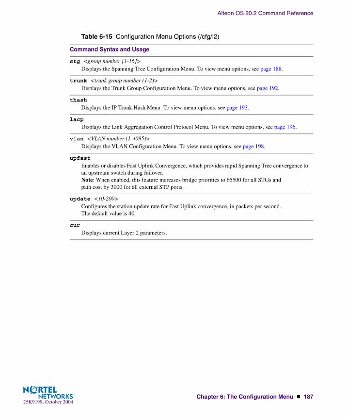
Alteon OS 20.2 Command Reference
Chapter 6: The Configuration Menu � 18725K9199, October 2004
Table 6-15 Configuration Menu Options (/cfg/l2)
Command Syntax and Usage
stg <group number [1-16]>Displays the Spanning Tree Configuration Menu. To view menu options, see page 188.
trunk <trunk group number (1-2)>Displays the Trunk Group Configuration Menu. To view menu options, see page 192.
thash
Displays the IP Trunk Hash Menu. To view menu options, see page 193.
lacp
Displays the Link Aggregation Control Protocol Menu. To view menu options, see page 196.
vlan <VLAN number (1-4095)> Displays the VLAN Configuration Menu. To view menu options, see page 198.
upfast
Enables or disables Fast Uplink Convergence, which provides rapid Spanning Tree convergence to an upstream switch during failover. Note: When enabled, this feature increases bridge priorities to 65500 for all STGs and path cost by 3000 for all external STP ports.
update <10-200> Configures the station update rate for Fast Uplink convergence, in packets per second. The default value is 40.
cur
Displays current Layer 2 parameters.

Alteon OS 20.2 Command Reference
188 � Chapter 6: The Configuration Menu25K9199, October 2004
/cfg/l2/stgSpanning Tree Configuration
Alteon OS supports the IEEE 802.1d Spanning Tree Protocol (STP). STG is used to prevent loops in the network topology. There are 16 spanning tree groups that can be configured on the switch (STG 16 is reserved for management). This command is turned on by default.
NOTE – When VRRP is used for active/active redundancy, STG must be enabled.
[Spanning Tree Group 1 Menu] brg - Bridge parameter menu port - Port parameter menu add - Add VLAN(s) to Spanning Tree Group remove - Remove VLAN(s) from Spanning Tree Group clear - Remove all VLANs from Spanning Tree Group on - Globally turn Spanning Tree ON off - Globally turn Spanning Tree OFF default - Default Spanning Tree and Member parameters cur - Display current bridge parameters
Table 6-16 Spanning Tree Configuration Menu (/cfg/l2/stg)
Command Syntax and Usage
brg
Displays the Bridge Spanning Tree Menu. To view menu options, see page 189.
port <port alias or number>Displays the Spanning Tree Port Menu. To view menu options, see page 191.
add <VLAN number (1-4095)>Associates a VLAN with a spanning tree and requires an external VLAN ID as a parameter.
remove <VLAN number (1-4095)>Breaks the association between a VLAN and a spanning tree and requires an external VLAN ID as a parameter.
clear
Removes all VLANs from a spanning tree.
on
Globally enables Spanning Tree Protocol.
off
Globally disables Spanning Tree Protocol.
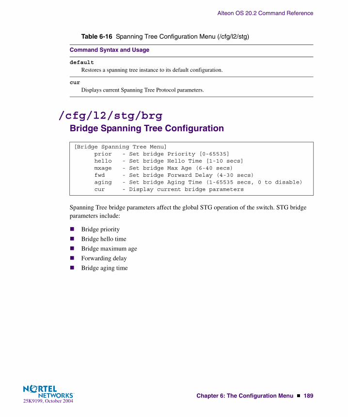
Alteon OS 20.2 Command Reference
Chapter 6: The Configuration Menu � 18925K9199, October 2004
/cfg/l2/stg/brgBridge Spanning Tree Configuration
Spanning Tree bridge parameters affect the global STG operation of the switch. STG bridge parameters include:
� Bridge priority
� Bridge hello time
� Bridge maximum age
� Forwarding delay
� Bridge aging time
default
Restores a spanning tree instance to its default configuration.
cur
Displays current Spanning Tree Protocol parameters.
[Bridge Spanning Tree Menu] prior - Set bridge Priority [0-65535] hello - Set bridge Hello Time [1-10 secs] mxage - Set bridge Max Age (6-40 secs) fwd - Set bridge Forward Delay (4-30 secs) aging - Set bridge Aging Time (1-65535 secs, 0 to disable) cur - Display current bridge parameters
Table 6-16 Spanning Tree Configuration Menu (/cfg/l2/stg)
Command Syntax and Usage

Alteon OS 20.2 Command Reference
190 � Chapter 6: The Configuration Menu25K9199, October 2004
When configuring STG bridge parameters, the following formulas must be used:
� 2*(fwd-1) > mxage
� 2*(hello+1) < mxage
Table 6-17 Bridge Spanning Tree Menu Options (/cfg/l2/stg/brg)
Command Syntax and Usage
prior <new bridge priority (0-65535)>Configures the bridge priority. The bridge priority parameter controls which bridge on the network is the STG root bridge. To make this switch the root bridge, configure the bridge priority lower than all other switches and bridges on your network. The lower the value, the higher the bridge pri-ority. The range is 0 to 65535, and the default is 32768.
hello <new bridge hello time (1-10 secs)>Configures the bridge hello time.The hello time specifies how often the root bridge transmits a configuration bridge protocol data unit (BPDU). Any bridge that is not the root bridge uses the root bridge hello value. The range is 1 to 10 seconds, and the default is 2 seconds.
mxage <new bridge max age (6-40 secs)>Configures the bridge maximum age. The maximum age parameter specifies the maximum time the bridge waits without receiving a configuration bridge protocol data unit before it re configures the STG network. The range is 6 to 40 seconds, and the default is 20 seconds.
fwd <new bridge Forward Delay (4-30 secs)>Configures the bridge forward delay parameter. The forward delay parameter specifies the amount of time that a bridge port has to wait before it changes from the listening state to the learning state and from the learning state to the forwarding state. The range is 4 to 30 seconds, and the default is 15 seconds.
aging <new bridge Aging Time (1-65535 secs, 0 to disable)>Configures the forwarding database aging time. The aging time specifies the amount of time the bridge waits without receiving a packet from a station before removing the station from the for-warding database. The range is 1 to 65535 seconds, and the default is 300 seconds. To disable aging, set this parameter to 0.
current
Displays the current bridge STG parameters.

Alteon OS 20.2 Command Reference
Chapter 6: The Configuration Menu � 19125K9199, October 2004
/cfg/l2/stg <STP Group Index>/port <port alias or number>
Spanning Tree Port Configuration
Spanning Tree port parameters are used to modify STG operation on an individual port basis. STG port parameters include:
� Port priority
� Port path cost
The port option of STG is turned on by default.
[Spanning Tree Port EXT1 Menu] prior - Set port Priority (0-255) cost - Set port Path Cost (1-65535, 0 for default) on - Turn port’s Spanning Tree ON off - Turn port’s Spanning Tree OFF cur - Display current port Spanning Tree parameters
Table 6-18 Spanning Tree Port Menu (/cfg/l2/stg/port)
Command Syntax and Usage
prior <new port Priority (0-255)>Configures the port priority. The port priority helps determine which bridge port becomes the des-ignated port. In a network topology that has multiple bridge ports connected to a single segment, the port with the lowest port priority becomes the designated port for the segment. The range is 0 to 255, and the default is 128.
cost <new port Path Cost (1-65535, 0 for default)>Configures the port path cost. The port path cost is used to help determine the designated port for a segment. Generally speaking, the faster the port, the lower the path cost. The range is 1 to 65535. The default is 10 for 100Mbps ports, and 1 for Gigabit ports. A value of 0 indicates that the default cost will be computed for an auto negotiated link speed.
on
Enables STG on the port.
off
Disables STG on the port.
cur
Displays the current STG port parameters.
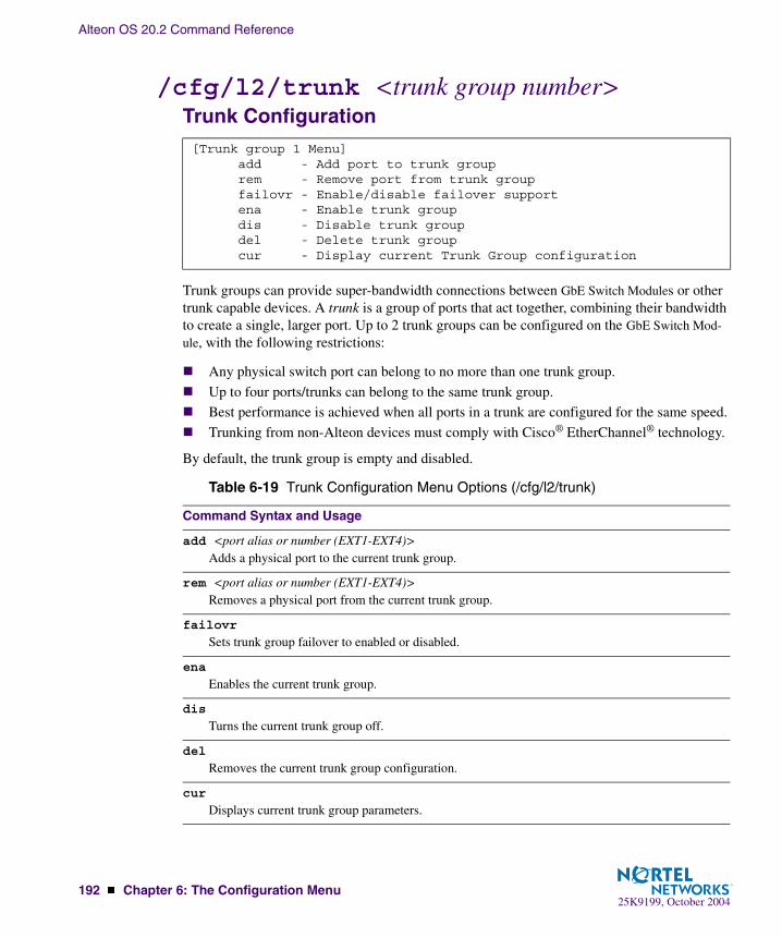
Alteon OS 20.2 Command Reference
192 � Chapter 6: The Configuration Menu25K9199, October 2004
/cfg/l2/trunk <trunk group number>Trunk Configuration
Trunk groups can provide super-bandwidth connections between GbE Switch Modules or other trunk capable devices. A trunk is a group of ports that act together, combining their bandwidth to create a single, larger port. Up to 2 trunk groups can be configured on the GbE Switch Mod-ule, with the following restrictions:
� Any physical switch port can belong to no more than one trunk group.
� Up to four ports/trunks can belong to the same trunk group.
� Best performance is achieved when all ports in a trunk are configured for the same speed.
� Trunking from non-Alteon devices must comply with Cisco® EtherChannel® technology.
By default, the trunk group is empty and disabled.
[Trunk group 1 Menu] add - Add port to trunk group rem - Remove port from trunk group failovr - Enable/disable failover support ena - Enable trunk group dis - Disable trunk group del - Delete trunk group cur - Display current Trunk Group configuration
Table 6-19 Trunk Configuration Menu Options (/cfg/l2/trunk)
Command Syntax and Usage
add <port alias or number (EXT1-EXT4)>Adds a physical port to the current trunk group.
rem <port alias or number (EXT1-EXT4)>Removes a physical port from the current trunk group.
failovr
Sets trunk group failover to enabled or disabled.
ena
Enables the current trunk group.
dis
Turns the current trunk group off.
del
Removes the current trunk group configuration.
cur
Displays current trunk group parameters.

Alteon OS 20.2 Command Reference
Chapter 6: The Configuration Menu � 19325K9199, October 2004
/cfg/l2/thashIP Trunk Hash menu
Use the following commands to configure IP trunk hash settings for the GbESM.
/cfg/l2/thash/l2Layer 2 IP Trunk Hash menu
Trunk hash parameters are set globally for the GbE Switch Module. You can enable one or two parameters, to configure any of the following valid combinations:
� SMAC (source MAC only)
� DMAC (destination MAC only)
� SIP (source IP only)
� DIP (destination IP only)
� SIP + DIP (source IP and destination IP)
[IP Trunk Hash Menu] l2 - L2 IP Trunk Hash Settings Menu l3 - L3 IP Trunk Hash Settings Menu cur - Display current IP trunk hash configuration
Table 6-20 IP Trunk Hash commands (/cfg/l2/thash)
Command Syntax and Usage
l2
Displays the layer 2 Trunk Hash Settings menu. To view menu options, see page 193.
l3
Displays the layer 3 Trunk Hash Settings menu. To view menu options, see page 194.
cur
Display current trunk hash configuration.
[l2 IP Trunk Hash Settings Menu] smac - Enable/disable smac hash dmac - Enable/disable dmac hash sip - Enable/disable sip hash dip - Enable/disable dip hash cur - Display current trunk hash setting
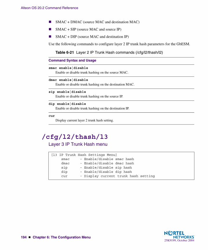
Alteon OS 20.2 Command Reference
194 � Chapter 6: The Configuration Menu25K9199, October 2004
� SMAC + DMAC (source MAC and destination MAC)
� SMAC + SIP (source MAC and source IP)
� SMAC + DIP (source MAC and destination IP)
Use the following commands to configure layer 2 IP trunk hash parameters for the GbESM.
/cfg/l2/thash/l3Layer 3 IP Trunk Hash menu
Table 6-21 Layer 2 IP Trunk Hash commands (/cfg/l2/thash/l2)
Command Syntax and Usage
smac enable|disable
Enable or disable trunk hashing on the source MAC.
dmac enable|disable
Enable or disable trunk hashing on the destination MAC.
sip enable|disable
Enable or disable trunk hashing on the source IP.
dip enable|disable
Enable or disable trunk hashing on the destination IP.
cur
Display current layer 2 trunk hash setting.
[l3 IP Trunk Hash Settings Menu] smac - Enable/disable smac hash dmac - Enable/disable dmac hash sip - Enable/disable sip hash dip - Enable/disable dip hash cur - Display current trunk hash setting

Alteon OS 20.2 Command Reference
Chapter 6: The Configuration Menu � 19525K9199, October 2004
Use the following commands to configure layer 3 IP trunk hash settings for the GbESM.
Table 6-22 Layer 3 IP Trunk Hash commands (/cfg/l2/thash/l3)
Command Syntax and Usage
smac enable|disable
Enable or disable trunk hashing on the source MAC.
dmac enable|disable
Enable or disable trunk hashing on the destination MAC.
sip enable|disable
Enable or disable trunk hashing on the source IP.
dip enable|disable
Enable or disable trunk hashing on the destination IP.
cur
Display current layer 3 trunk hash setting.
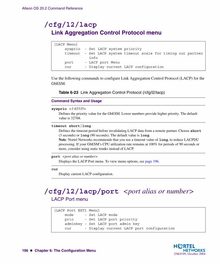
Alteon OS 20.2 Command Reference
196 � Chapter 6: The Configuration Menu25K9199, October 2004
/cfg/l2/lacpLink Aggregation Control Protocol menu
Use the following commands to configure Link Aggregation Control Protocol (LACP) for the GbESM.
/cfg/l2/lacp/port <port alias or number>LACP Port menu
[LACP Menu] sysprio - Set LACP system priority timeout - Set LACP system timeout scale for timing out partner info port - LACP port Menu cur - Display current LACP configuration
Table 6-23 Link Aggregation Control Protocol (/cfg/l2/lacp)
Command Syntax and Usage
sysprio <1-65535>Defines the priority value for the GbESM. Lower numbers provide higher priority. The default value is 32768.
timeout short|long
Defines the timeout period before invalidating LACP data from a remote partner. Choose short (3 seconds) or long (90 seconds). The default value is long. Note: Nortel Networks recommends that you use a timeout value of long, to reduce LACPDU processing. If your GbESM’s CPU utilization rate remains at 100% for periods of 90 seconds or more, consider using static trunks instead of LACP.
port <port alias or number>Displays the LACP Port menu. To view menu options, see page 196.
cur
Display current LACP configuration.
[LACP Port EXT1 Menu] mode - Set LACP mode prio - Set LACP port priority adminkey - Set LACP port admin key cur - Display current LACP port configuration

Alteon OS 20.2 Command Reference
Chapter 6: The Configuration Menu � 19725K9199, October 2004
Use the following commands to configure Link Aggregation Control Protocol (LACP) for the selected port.
Table 6-24 Link Aggregation Control Protocol (/cfg/l2/lacp/port)
Command Syntax and Usage
mode off|active|passive
Set the LACP mode for this port, as follows:
� off Turn LACP off for this port. You can use this port to manually configure a static trunk. The default value is off.
� active Turn LACP on and set this port to active. Active ports initiate LACPDUs.
� passive Turn LACP on and set this port to passive. Passive ports do not initiate LACPDUs, but respond to LACPDUs from active ports.
prio <1-65535>Sets the priority value for the selected port. Lower numbers provide higher priority. Default is 128.
adminkey <1-65535>Set the admin key for this port. Only ports with the same admin key and oper key (operational state) can form a LACP trunk group.
cur
Displays the current LACP configuration for this port.
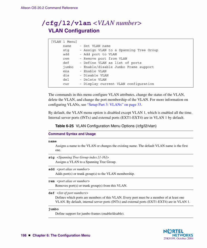
Alteon OS 20.2 Command Reference
198 � Chapter 6: The Configuration Menu25K9199, October 2004
/cfg/l2/vlan <VLAN number>VLAN Configuration
The commands in this menu configure VLAN attributes, change the status of the VLAN, delete the VLAN, and change the port membership of the VLAN. For more information on configuring VLANs, see “Setup Part 3: VLANs” on page 33.
By default, the VLAN menu option is disabled except VLAN 1, which is enabled all the time. Internal server ports (INTx) and external ports (EXT1-EXT4) are in VLAN 1 by default.
[VLAN 1 Menu] name - Set VLAN name stg - Assign VLAN to a Spanning Tree Group add - Add port to VLAN rem - Remove port from VLAN def - Define VLAN as list of ports jumbo - Enable/disable Jumbo Frame support ena - Enable VLAN dis - Disable VLAN del - Delete VLAN cur - Display current VLAN configuration
Table 6-25 VLAN Configuration Menu Options (/cfg/l2/vlan)
Command Syntax and Usage
name
Assigns a name to the VLAN or changes the existing name. The default VLAN name is the first one.
stg <Spanning Tree Group index [1-16]>Assigns a VLAN to a Spanning Tree Group.
add <port alias or number>Adds port(s) or trunk group(s) to the VLAN membership.
rem <port alias or number>Removes port(s) or trunk group(s) from this VLAN.
def <list of port numbers>Defines which ports are members of this VLAN. Every port must be a member of at least one VLAN. By default, internal server ports (INTx) and external ports (EXT1-EXT4) are in VLAN 1.
jumbo
Define support for jumbo frames (enable/disable).

Alteon OS 20.2 Command Reference
Chapter 6: The Configuration Menu � 19925K9199, October 2004
NOTE – All ports must belong to at least one VLAN. Any port which is removed from a VLAN and which is not a member of any other VLAN is automatically added to default VLAN 1. You cannot remove a port from VLAN 1 if the port has no membership in any other VLAN. Also, you cannot add a port to more than one VLAN unless the port has VLAN tagging turned on (see the tag command on page 181).
ena
Enables this VLAN.
dis
Disables this VLAN without removing it from the configuration.
del
Deletes this VLAN.
cur
Displays the current VLAN configuration.
Table 6-25 VLAN Configuration Menu Options (/cfg/l2/vlan)
Command Syntax and Usage

Alteon OS 20.2 Command Reference
200 � Chapter 6: The Configuration Menu25K9199, October 2004
/cfg/l3Layer 3 Menu
[Layer 3 Menu] if - Interface Menu gw - Default Gateway Menu route - Static Route Menu frwd - Forwarding Menu nwf - Network Filters Menu rmap - Route Map Menu rip1 - Routing Information Protocol Menu ospf - Open Shortest Path First (OSPF) Menu bgp - Border Gateway Protocol Menu igmp - IGMP Menu port - IP Port Menu dns - Domain Name System Menu bootp - Bootstrap Protocol Relay Menu vrrp - Virtual Router Redundancy Protocol Menu rtrid - Set router ID metrc - Set default gateway metric cur - Display current IP configuration
Table 6-26 Configuration Menu Options (/cfg/l3)
Command Syntax and Usage
if <interface number (1-128)>Displays the IP Interface Menu. To view menu options, see page 202.
gw <default gateway number (1-132)>Displays the IP Default Gateway Menu. To view menu options, see page 203.
route
Displays the IP Static Route Menu. To view menu options, see page 205.
frwd
Displays the IP Forwarding Menu. To view menu options, see page 206.
nwf <Network filter number [1-256]>Displays the Network Filter Configuration Menu. To view menu options see page 208.
rmap <route map number [1-32]>Displays the Route Map Menu. To view menu options see page 209.
rip1
Displays the Routing Interface Protocol version 1 Menu. To view menu options, see page 213.

Alteon OS 20.2 Command Reference
Chapter 6: The Configuration Menu � 20125K9199, October 2004
ospf
Displays the OSPF Menu. To view menu options, see page 215.
bgp
Displays the Border Gateway Protocol Menu. To view menu options, see page 224.
igmp
Displays the IGMP Menu. To view menu options, see page 230.
port <port alias or number>Displays the IP Port Menu. To view menu options, see page 233.
dns
Displays the IP Domain Name System Menu. To view menu options, see page 234.
bootp
Displays the Bootstrap Protocol Menu. To view menu options, see page 235.
vrrp
Displays the Virtual Router Redundancy Configuration Menu. To view menu options, see page 236.
rtrid <<IP address (such as, 192.4.17.101)>Sets the router ID.
metrc strict|roundrobinSets the default gateway metric for strict or roundrobin. The default gateway metric is strict. For more information on gateway metrics, see page 248.
cur
Displays the current IP configuration.
Table 6-26 Configuration Menu Options (/cfg/l3)
Command Syntax and Usage

Alteon OS 20.2 Command Reference
202 � Chapter 6: The Configuration Menu25K9199, October 2004
/cfg/l3/if <interface number>IP Interface Configuration
The GbE Switch Module can be configured with up to 128 IP interfaces. Each IP interface repre-sents the GbE Switch Module on an IP subnet on your network. The Interface option is disabled by default.
NOTE – To maintain connection between the management module and the GbE Switch Mod-ule, use the management module interface to change the IP address of the switch.
[IP Interface 1 Menu] addr - Set IP address mask - Set subnet mask vlan - Set VLAN number relay - Enable or disable BOOTP relay ena - Enable interface dis - Disable interface del - Delete interface cur - Display current interface configuration
Table 6-27 IP Interface Menu Options (/cfg/l3/if)
Command Syntax and Usage
addr <IP address (such as 192.4.17.101)>Configures the IP address of the switch interface using dotted decimal notation.
mask <IP subnet mask (such as 255.255.255.0)>Configures the IP subnet address mask for the interface using dotted decimal notation.
vlan <VLAN number (1-4095)>Configures the VLAN number for this interface. Each interface can belong to one VLAN, though any VLAN can have multiple IP interfaces in it.
relay disable|enable
Enables or disables the BOOTP relay on this interface. It is enabled by default.
ena
Enables this IP interface.
dis
Disables this IP interface.

Alteon OS 20.2 Command Reference
Chapter 6: The Configuration Menu � 20325K9199, October 2004
/cfg/l3/gw <gateway number>Default Gateway Configuration
NOTE – The switch can be configured with up to 132 gateways. Gateways one to four are reserved for default gateway load balancing. Gateway 132 is reserved for the management VLAN.
This option is disabled by default.
del
Removes this IP interface.
cur
Displays the current interface settings.
[Default gateway 1 Menu] addr - Set IP address intr - Set interval between ping attempts retry - Set number of failed attempts to declare gateway DOWN vlan - Set VLAN number arp - Enable/disable ARP only health checks ena - Enable default gateway dis - Disable default gateway del - Delete default gateway cur - Display current default gateway configuration
Table 6-28 Default Gateway Options (/cfg/l3/gw)
Command Syntax and Usage
addr <default gateway address (such as, 192.4.17.44)>Configures the IP address of the default IP gateway using dotted decimal notation.
intr <0-60 seconds>The switch pings the default gateway to verify that it’s up. The intr option sets the time between health checks. The range is from 1 to 120 seconds. The default is 2 seconds.
retry <number of attempts (1-120)>Sets the number of failed health check attempts required before declaring this default gateway inoperative. The range is from 1 to 120 attempts. The default is 8 attempts.
Table 6-27 IP Interface Menu Options (/cfg/l3/if)
Command Syntax and Usage

Alteon OS 20.2 Command Reference
204 � Chapter 6: The Configuration Menu25K9199, October 2004
Default Gateway Metrics
For information about configuring which gateway is selected when multiple default gateways are enabled, see page 204.
vlan <VLAN number (1-4095)>Sets the VLAN to be assigned to this default IP gateway.
arp disable|enable
Enables or disables Address Resolution Protocol (ARP) health checks. This command is disabled by default.
ena
Enables the gateway for use.
dis
Disables the gateway.
del
Deletes the gateway from the configuration.
cur
Displays the current gateway settings.
Table 6-28 Default Gateway Options (/cfg/l3/gw)
Command Syntax and Usage

Alteon OS 20.2 Command Reference
Chapter 6: The Configuration Menu � 20525K9199, October 2004
/cfg/l3/routeIP Static Route Configuration
Up to 128 static routes can be configured.
[IP Static Route Menu] add - Add static route rem - Remove static route cur - Display current static routes
Table 6-29 IP Static Route Configuration Menu Options (cfg/l3/route)
Command Syntax and Usage
add <destination> <mask> <gateway> <interface number>Adds a static route. You will be prompted to enter a destination IP address, destination subnet mask, and gateway address. Enter all addresses using dotted decimal notation.
rem <destination> <mask>Removes a static route. The destination address of the route to remove must be specified using dot-ted decimal notation.
cur
Displays the current IP static routes.

Alteon OS 20.2 Command Reference
206 � Chapter 6: The Configuration Menu25K9199, October 2004
/cfg/l3/frwdIP Forwarding Configuration
/cfg/l3/frwd/localLocal Network Route Caching Definition
[IP Forwarding Menu] local - Local network definition for route caching menu dirbr - Enable or disable forwarding directed broadcasts on - Globally turn IP Forwarding ON off - Globally turn IP Forwarding OFF cur - Display current IP Forwarding configuration
Table 6-30 IP Forwarding Configuration Menu Options (/cfg/l3/frwd)
Command Syntax and Usage
local
Displays the menu used to define local network for route caching. Up to five local networks (lnets) can be configured. To view menu options, see page 206.
dirbr disable|enable
Enables or disables forwarding directed broadcasts. This command is disabled by default.
on
Enables IP forwarding (routing) on the GbE Switch Module.
off
Disables IP forwarding (routing) on the GbE Switch Module. Forwarding is turned off by default.
cur
Displays the current IP forwarding settings.
[IP Local Networks Menu] add - Add local network definition rem - Remove local network definition cur - Display current local network definitions

Alteon OS 20.2 Command Reference
Chapter 6: The Configuration Menu � 20725K9199, October 2004
This menu is used for adding local networks by setting the local network address and netmask for the route cache, and to remove local networks.
Defining IP Address Ranges for the Local Route CacheThe Local Route Cache lets you use switch resources more efficiently, by reducing the size of the ARP table on the GbE Switch Module. The /cfg/l3/frwd/local/add parameters define a range of addresses that will be cached on the GbE Switch Module. The local network address is used to define the base IP address in the range which will be cached, and the local network mask is the mask which is applied to produce the range. To determine if a route should be added to the memory cache, the destination address is masked (bitwise AND) with the local network mask and checked against the local network address.
By default, the local network address and mask are both set to 0.0.0.0. This produces a range that includes all Internet addresses for route caching: 0.0.0.0 through 255.255.255.255.
Addresses to be cached are subnets that are directly connected and for which there is an inter-face configured on the GbE Switch Module. To limit the route cache to your local hosts, you could configure the parameters as shown in the examples in the following table.
Table 2 IP Local Networks Menu Options (/cfg/l3/frwd/local)
Command Syntax and Usage
add <Local Network Address> <Local Network Mask>Adds a definition for a local network. For details, see “Defining IP Address Ranges for the Local Route Cache” below.
rem <Local Network Address> <Local Network Mask>Removes a definition for a local network.
cur
Displays the current local network definitions.
Table 6-31 Local Routing Cache Address Ranges
Local Host Address Range Address Mask
0.0.0.0 - 127.255.255.255 0.0.0.0 128.0.0.0
128.0.0.0 - 255.255.255.255 128.0.0.0 128.0.0.0
205.32.0.0 - 205.32.255.255 205.32.0.0 255.255.0.0
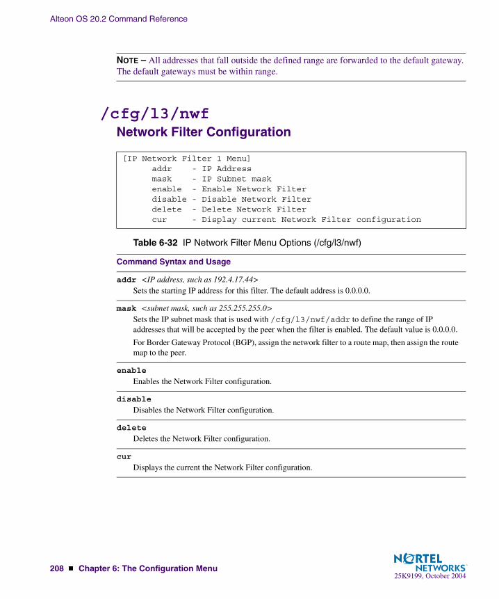
Alteon OS 20.2 Command Reference
208 � Chapter 6: The Configuration Menu25K9199, October 2004
NOTE – All addresses that fall outside the defined range are forwarded to the default gateway. The default gateways must be within range.
/cfg/l3/nwfNetwork Filter Configuration
[IP Network Filter 1 Menu] addr - IP Address mask - IP Subnet mask enable - Enable Network Filter disable - Disable Network Filter delete - Delete Network Filter cur - Display current Network Filter configuration
Table 6-32 IP Network Filter Menu Options (/cfg/l3/nwf)
Command Syntax and Usage
addr <IP address, such as 192.4.17.44>Sets the starting IP address for this filter. The default address is 0.0.0.0.
mask <subnet mask, such as 255.255.255.0>Sets the IP subnet mask that is used with /cfg/l3/nwf/addr to define the range of IP addresses that will be accepted by the peer when the filter is enabled. The default value is 0.0.0.0.
For Border Gateway Protocol (BGP), assign the network filter to a route map, then assign the route map to the peer.
enable
Enables the Network Filter configuration.
disable
Disables the Network Filter configuration.
delete
Deletes the Network Filter configuration.
cur
Displays the current the Network Filter configuration.

Alteon OS 20.2 Command Reference
Chapter 6: The Configuration Menu � 20925K9199, October 2004
/cfg/l3/rmap <route map number>Routing Map Configuration
NOTE – The map number (1-32) represents the routing map you wish to configure.
Routing maps control and modify routing information.
[IP Route Map 1 Menu] alist - Access List number aspath - AS Filter Menu ap - Set as-path prepend of the matched route lp - Set local-preference of the matched route metric - Set metric of the matched route type - Set OSPF metric-type of the matched route prec - Set the precedence of this route map weight - Set weight of the matched route enable - Enable route map disable - Disable route map delete - Delete route map cur - Display current route map configuration
Table 6-33 Routing Map Menu Options (/cfg/l3/rmap)
Command Syntax and Usage
alist <number 1-8>Displays the Access List menu. For more information, see page 211.
aspath <number 1-8>Displays the Autonomous System (AS) Filter menu. For more information, see page 212.
ap <AS number> [<AS number>] [<AS number>]|noneSets the AS path preference of the matched route. One to three path preferences can be configured.
lp <(0-4294967294)>|noneSets the local preference of the matched route, which affects both inbound and outbound direc-tions. The path with the higher preference is preferred.
metric <(0-4294967294)>|noneSets the metric of the matched route.

Alteon OS 20.2 Command Reference
210 � Chapter 6: The Configuration Menu25K9199, October 2004
type <value (1|2)>|noneAssigns the type of OSPF metric. The default is type 1.
� Type 1—External routes are calculated using both internal and external metrics. � Type 2—External routes are calculated using only the external metrics. Type 2 routes have
more cost than Type 2. � none—Removes the OSPF metric.
prec <value (1-256)>Sets the precedence of the route map. The smaller the value, the higher the precedence. Default value is 10.
weight <value (0-65534)>|noneSets the weight of the route map.
enable
Enables the route map.
disable
Disables the route map.
delete
Deletes the route map.
cur
Displays the current route configuration.
Table 6-33 Routing Map Menu Options (/cfg/l3/rmap) (Continued)
Command Syntax and Usage

Alteon OS 20.2 Command Reference
Chapter 6: The Configuration Menu � 21125K9199, October 2004
/cfg/l3/rmap <route map number/alist <access list number>
IP Access List Configuration Menu
NOTE – The route map number (1-32) and the access list number (1-8) represent the IP access list you wish to configure.
[IP Access List 1 Menu] nwf - Network Filter number metric - Metric action - Set Network Filter action enable - Enable Access List disable - Disable Access List delete - Delete Access List cur - Display current Access List configuration
Table 6-34 IP Access List Menu Options (/cfg/l3/rmap/alist)
Command Syntax and Usage
nwf <network filter number (1-256)> Sets the network filter number. See “/cfg/l3/nwf” on page 208 for details.
metric <(1-4294967294)>|noneSets the metric value in the AS-External (ASE) LSA.
action permit|deny
Permits or denies action for the access list.
enable
Enables the access list.
disable
Disables the access list.
delete
Deletes the access list.
cur
Displays the current Access List configuration.

Alteon OS 20.2 Command Reference
212 � Chapter 6: The Configuration Menu25K9199, October 2004
/cfg/l3/rmap <route map number> aspath <autonomous system path>
Autonomous System Filter Path
NOTE – The rmap number (1-32) and the path number (1-8) represent the AS path you wish to configure.
[AS Filter 1 Menu] as - AS number action - Set AS Filter action enable - Enable AS Filter disable - Disable AS Filter delete - Delete AS Filter cur - Display current AS Filter configuration
Table 6-35 AS Filter Menu Options (/cfg/l3/rmap/aspath)
Command Syntax and Usage
as <AS number (1-65535)> Sets the Autonomous System filter’s path number.
action <permit|deny (p|d)>Permits or denies Autonomous System filter action.
enable
Enables the Autonomous System filter.
disable
Disables the Autonomous System filter.
delete
Deletes the Autonomous System filter.
current
Displays the current Autonomous System filter configuration.
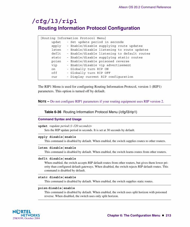
Alteon OS 20.2 Command Reference
Chapter 6: The Configuration Menu � 21325K9199, October 2004
/cfg/l3/rip1Routing Information Protocol Configuration
The RIP1 Menu is used for configuring Routing Information Protocol, version 1 (RIP1) parameters. This option is turned off by default.
NOTE – Do not configure RIP1 parameters if your routing equipment uses RIP version 2.
[Routing Information Protocol Menu] updat - Set update period in seconds spply - Enable/disable supplying route updates lsten - Enable/disable listening to route updates deflt - Enable/disable listening to default routes statc - Enable/disable supplying static routes poisn - Enable/disable poisoned reverse vip - Enable/disable vip advertisement on - Globally turn RIP ON off - Globally turn RIP OFF cur - Display current RIP configuration
Table 6-36 Routing Information Protocol Menu (/cfg/l3/rip1)
Command Syntax and Usage
updat <update period (1-120 seconds)>Sets the RIP update period in seconds. It is set at 30 seconds by default.
spply disable|enable
This command is disabled by default. When enabled, the switch supplies routes to other routers.
lsten disable|enable
This command is disabled by default. When enabled, the switch learns routes from other routers.
deflt disable|enable
When enabled, the switch accepts RIP default routes from other routers, but gives them lower pri-ority than configured default gateways. When disabled, the switch rejects RIP default routes. This command is disabled by default.
statc disable|enable
This command is disabled by default. When enabled, the switch supplies static routes.
poisn disable|enableThis command is disabled by default. When enabled, the switch uses split horizon with poisoned reverse. When disabled, the switch uses only split horizon.

Alteon OS 20.2 Command Reference
214 � Chapter 6: The Configuration Menu25K9199, October 2004
vip disable|enable
Enables or disables the advertisement of virtual IP addresses as Host Routes. If a VIP route exists in a routing table, it will always be advertised except when it is included in another network route that is already being advertised.
Note: If all real servers behind a VIP go down, the route gets removed from the routing table, and will not be advertised. If we disable all the real servers using operation command, the VIP route does not get eliminated from the routing table, and the switch will continue to advertise the route.
on
Globally turns RIP ON.
off
Globally turns RIP OFF.
cur
Displays the current RIP configuration.
Table 6-36 Routing Information Protocol Menu (/cfg/l3/rip1)
Command Syntax and Usage

Alteon OS 20.2 Command Reference
Chapter 6: The Configuration Menu � 21525K9199, October 2004
/cfg/l3/ospfOpen Shortest Path First Configuration
[Open Shortest Path First Menu] aindex - OSPF Area (index) menu range - OSPF Summary Range menu if - OSPF Interface menu virt - OSPF Virtual Links menu md5key - OSPF MD5 Key Menu host - OSPF Host Entry menu redist - OSPF Route Redistribute menu lsdb - Set the LSDB limit default - Originate default route information on - Globally turn OSPF ON off - Globally turn OSPF OFF cur - Display current OSPF configuration
Table 6-37 OSPF Configuration Menu Options (/cfg/l3/ospf)
Command Syntax and Usage
aindex <area index (0-2)>Displays the area index menu. This area index does not represent the actual OSPF area number. See page 216 to view menu options.
range <range number (1-16)>Displays summary routes menu for up to 16 IP addresses. See page 218 to view menu options.
if <interface number (1-128)>Displays the OSPF interface configuration menu. See page 219 to view menu options.
virt <virtual link (1-3)>Displays the Virtual Links menu used to configure OSPF for a Virtual Link. See page 220 to view menu options.
md5key <key ID [1-255>Assigns a string to MD5 authentication key. See
host <host entry number (1-128)>Displays the menu for configuring OSPF for the host routes. Up to 128 host routes can be config-ured. Host routes are used for advertising network device IP addresses to external networks to per-form server load balancing within OSPF. It also makes Area Border Route (ABR) load sharing and ABR failover possible. See page 222 to view menu options.
redist <fixed|static|rip|ebgp|ibgp>Displays Route Distribution Menu See page 223 to view menu options.

Alteon OS 20.2 Command Reference
216 � Chapter 6: The Configuration Menu25K9199, October 2004
/cfg/l3/ospf/aindexArea Index Configuration Menu
lsdb <LSDB limit (0-2000, 0 for no limit)>Sets the link state database limit.
default <metric [1-16777215]> <metric-type 1|2>|noneSets one default route among multiple choices in an area. Use none for no default.
on
Enables OSPF on the GbE Switch Module.
off
Disables OSPF on the GbE Switch Module.
cur
Displays the current OSPF configuration settings.
[OSPF Area (index) 1 Menu] areaid - Set area ID type - Set area type metric - Set stub area metric auth - Set authentication type spf - Set time interval between two SPF calculations enable - Enable area disable - Disable area delete - Delete area cur - Display current OSPF area configuration
Table 6-37 OSPF Configuration Menu Options (/cfg/l3/ospf)
Command Syntax and Usage
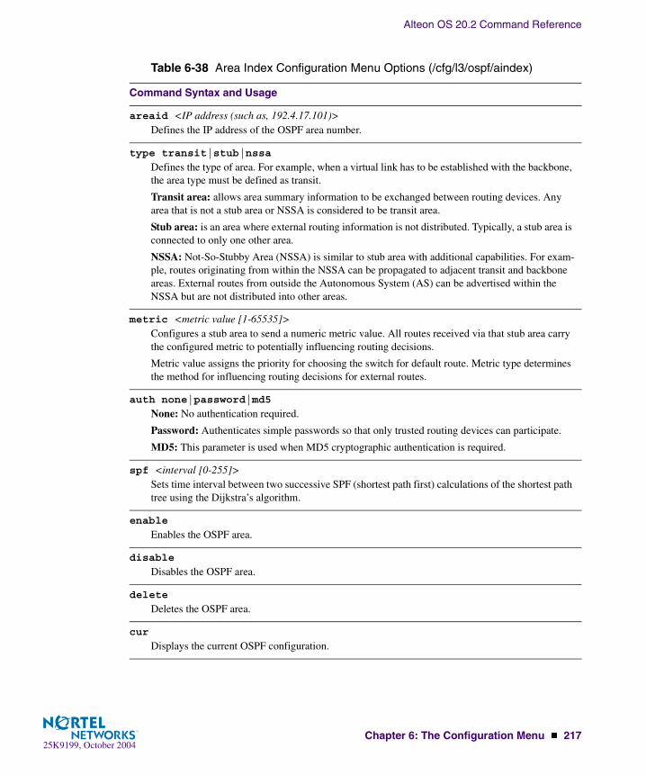
Alteon OS 20.2 Command Reference
Chapter 6: The Configuration Menu � 21725K9199, October 2004
Table 6-38 Area Index Configuration Menu Options (/cfg/l3/ospf/aindex)
Command Syntax and Usage
areaid <IP address (such as, 192.4.17.101)>Defines the IP address of the OSPF area number.
type transit|stub|nssa
Defines the type of area. For example, when a virtual link has to be established with the backbone, the area type must be defined as transit.
Transit area: allows area summary information to be exchanged between routing devices. Any area that is not a stub area or NSSA is considered to be transit area.
Stub area: is an area where external routing information is not distributed. Typically, a stub area is connected to only one other area.
NSSA: Not-So-Stubby Area (NSSA) is similar to stub area with additional capabilities. For exam-ple, routes originating from within the NSSA can be propagated to adjacent transit and backbone areas. External routes from outside the Autonomous System (AS) can be advertised within the NSSA but are not distributed into other areas.
metric <metric value [1-65535]>Configures a stub area to send a numeric metric value. All routes received via that stub area carry the configured metric to potentially influencing routing decisions.
Metric value assigns the priority for choosing the switch for default route. Metric type determines the method for influencing routing decisions for external routes.
auth none|password|md5
None: No authentication required.
Password: Authenticates simple passwords so that only trusted routing devices can participate.
MD5: This parameter is used when MD5 cryptographic authentication is required.
spf <interval [0-255]>Sets time interval between two successive SPF (shortest path first) calculations of the shortest path tree using the Dijkstra’s algorithm.
enable
Enables the OSPF area.
disable
Disables the OSPF area.
delete
Deletes the OSPF area.
cur
Displays the current OSPF configuration.
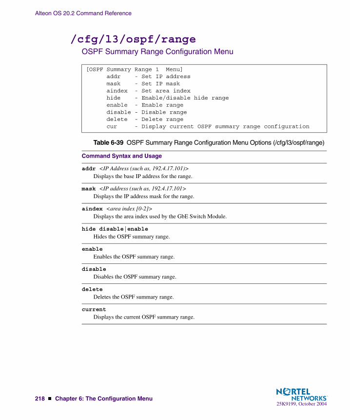
Alteon OS 20.2 Command Reference
218 � Chapter 6: The Configuration Menu25K9199, October 2004
/cfg/l3/ospf/rangeOSPF Summary Range Configuration Menu
[OSPF Summary Range 1 Menu] addr - Set IP address mask - Set IP mask aindex - Set area index hide - Enable/disable hide range enable - Enable range disable - Disable range delete - Delete range cur - Display current OSPF summary range configuration
Table 6-39 OSPF Summary Range Configuration Menu Options (/cfg/l3/ospf/range)
Command Syntax and Usage
addr <IP Address (such as, 192.4.17.101)>Displays the base IP address for the range.
mask <IP address (such as, 192.4.17.101>Displays the IP address mask for the range.
aindex <area index [0-2]>Displays the area index used by the GbE Switch Module.
hide disable|enable
Hides the OSPF summary range.
enable
Enables the OSPF summary range.
disable
Disables the OSPF summary range.
delete
Deletes the OSPF summary range.
current
Displays the current OSPF summary range.

Alteon OS 20.2 Command Reference
Chapter 6: The Configuration Menu � 21925K9199, October 2004
/cfg/l3/ospf/ifOSPF Interface Configuration Menu
[OSPF Interface 1 Menu] aindex - Set area index prio - Set interface router priority cost - Set interface cost hello - Set hello interval in seconds dead - Set dead interval in seconds trans - Set transit delay in seconds retra - Set retransmit interval in seconds key - Set authentication key mdkey - Set MD5 key ID enable - Enable interface disable - Disable interface delete - Delete interface cur - Display current OSPF interface configuration
Table 6-40 OSPF Interface Configuration Menu Options (/cfg/l3/ospf/if)
Command Syntax and Usage
aindex <area index [0-2]>Displays the OSPF area index.
prio <priority value (0-127)>Displays the assigned priority value to the GbE Switch Module’s OSPF interfaces.
(A priority value of 127 is the highest and 1 is the lowest. A priority value of 0 specifies that the interface cannot be used as Designated Router (DR) or Backup Designated Router (BDR).)
cost <cost value (1-65535)>Displays cost set for the selected path—preferred or backup. Usually the cost is inversely propor-tional to the bandwidth of the interface. Low cost indicates high bandwidth.
hello <value [1-65535]>Displays the interval in seconds between the hello packets for the intefaces.
dead <value [1-65535]>Displays the health parameters of a hello packet, which is set for an interval of seconds before declaring a silent router to be down.
trans <value [0-3600]>Displays the transit delay in seconds.
retra <value [0-3600]>Displays the retransmit interval in seconds.

Alteon OS 20.2 Command Reference
220 � Chapter 6: The Configuration Menu25K9199, October 2004
/cfg/l3/ospf/virtOSPF Virtual Link Configuration Menu
key <key> | noneSets the authentication key to clear the password.
mdkey <key ID [1-255]>|noneAssigns an MD5 key to the interface.
enable
Enables OSPF interface.
disable
Disables OSPF interface.
delete
Deletes OSPF interface.
cur
Displays the current settings for OSPF interface.
[OSPF Virtual Link 1 Menu] aindex - Set area index hello - Set hello interval in seconds dead - Set dead interval in seconds trans - Set transit delay in seconds retra - Set retransmit interval in seconds nbr - Set router ID of virtual neighbor key - Set authentication key mdkey - Set MD5 key ID enable - Enable interface disable - Disable interface delete - Delete interface cur - Display current OSPF interface configuration
Table 6-40 OSPF Interface Configuration Menu Options (/cfg/l3/ospf/if)
Command Syntax and Usage

Alteon OS 20.2 Command Reference
Chapter 6: The Configuration Menu � 22125K9199, October 2004
Table 6-41 OSPF Virtual Link Configuration Menu Options (/cfg/l3/ospf/virt)
Command Syntax and Usage
aindex <area index [0-2]>Displays the OSPF area index.
hello <value [1-65535]>Displays the authentication parameters of a hello packet, which is set to be in an interval of seconds.
dead <value [1-65535]>Displays the health parameters of a hello packet, which is set to be in an interval of seconds. Default is 40 seconds.
trans <value [1-3600]>Displays the delay in transit in seconds. Default is one seconds.
retra <value [1-3600]>Displays the retransmit interval in seconds. Default is five seconds.
nbr <NBR router ID (IP address)>Displays the router ID of the virtual neighbor. Default is 0.0.0.0.
key <password>Displays the password (up to eight characters) for each virtual link. Default is none.
mdkey <key ID [1-256]>|noneSets MD5 key ID for each virtual link. Default is none.
enable
Enables OSPF virtual link.
disable
Disables OSPF virtual link.
delete
Deletes OSPF virtual link.
cur
Displays the current OSPF virtual link settings.
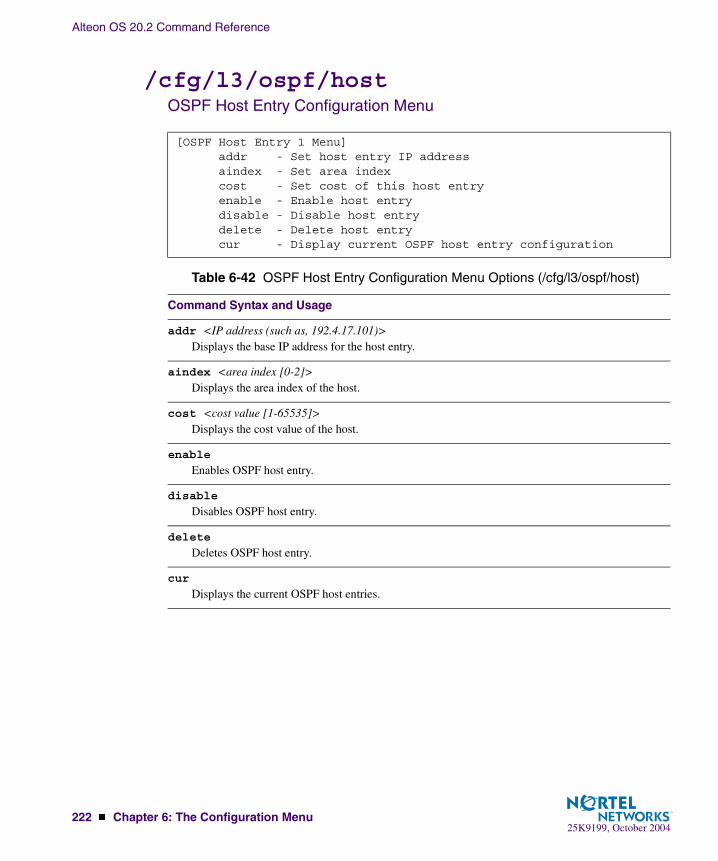
Alteon OS 20.2 Command Reference
222 � Chapter 6: The Configuration Menu25K9199, October 2004
/cfg/l3/ospf/hostOSPF Host Entry Configuration Menu
[OSPF Host Entry 1 Menu] addr - Set host entry IP address aindex - Set area index cost - Set cost of this host entry enable - Enable host entry disable - Disable host entry delete - Delete host entry cur - Display current OSPF host entry configuration
Table 6-42 OSPF Host Entry Configuration Menu Options (/cfg/l3/ospf/host)
Command Syntax and Usage
addr <IP address (such as, 192.4.17.101)>Displays the base IP address for the host entry.
aindex <area index [0-2]>Displays the area index of the host.
cost <cost value [1-65535]>Displays the cost value of the host.
enable
Enables OSPF host entry.
disable
Disables OSPF host entry.
delete
Deletes OSPF host entry.
cur
Displays the current OSPF host entries.
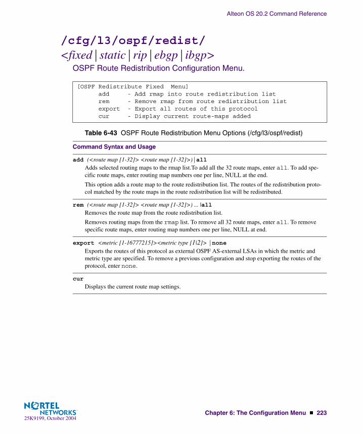
Alteon OS 20.2 Command Reference
Chapter 6: The Configuration Menu � 22325K9199, October 2004
/cfg/l3/ospf/redist/<fixed|static|rip|ebgp|ibgp>
OSPF Route Redistribution Configuration Menu.
[OSPF Redistribute Fixed Menu] add - Add rmap into route redistribution list rem - Remove rmap from route redistribution list export - Export all routes of this protocol cur - Display current route-maps added
Table 6-43 OSPF Route Redistribution Menu Options (/cfg/l3/ospf/redist)
Command Syntax and Usage
add (<route map [1-32]> <route map [1-32]>)|allAdds selected routing maps to the rmap list.To add all the 32 route maps, enter all. To add spe-cific route maps, enter routing map numbers one per line, NULL at the end.
This option adds a route map to the route redistribution list. The routes of the redistribution proto-col matched by the route maps in the route redistribution list will be redistributed.
rem (<route map [1-32]> <route map [1-32]>) ... |allRemoves the route map from the route redistribution list.
Removes routing maps from the rmap list. To remove all 32 route maps, enter all. To remove specific route maps, enter routing map numbers one per line, NULL at end.
export <metric [1-16777215]><metric type [1|2]> |none Exports the routes of this protocol as external OSPF AS-external LSAs in which the metric and metric type are specified. To remove a previous configuration and stop exporting the routes of the protocol, enter none.
cur
Displays the current route map settings.
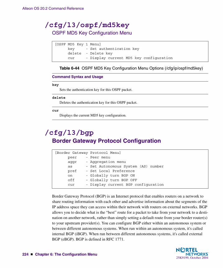
Alteon OS 20.2 Command Reference
224 � Chapter 6: The Configuration Menu25K9199, October 2004
/cfg/l3/ospf/md5keyOSPF MD5 Key Configuration Menu
/cfg/l3/bgpBorder Gateway Protocol Configuration
Border Gateway Protocol (BGP) is an Internet protocol that enables routers on a network to share routing information with each other and advertise information about the segments of the IP address space they can access within their network with routers on external networks. BGP allows you to decide what is the “best” route for a packet to take from your network to a desti-nation on another network, rather than simply setting a default route from your border router(s) to your upstream provider(s). You can configure BGP either within an autonomous system or between different autonomous systems. When run within an autonomous system, it's called internal BGP (iBGP). When run between different autonomous systems, it's called external BGP (eBGP). BGP is defined in RFC 1771.
[OSPF MD5 Key 1 Menu] key - Set authentication key delete - Delete key cur - Display current MD5 key configuration
Table 6-44 OSPF MD5 Key Configuration Menu Options (/cfg/ip/ospf/md5key)
Command Syntax and Usage
key
Sets the authentication key for this OSPF packet.
delete
Deletes the authentication key for this OSPF packet.
cur
Displays the current MD5 key configuration.
[Border Gateway Protocol Menu] peer - Peer menu aggr - Aggregation menu as - Set Autonomous System (AS) number pref - Set Local Preference on - Globally turn BGP ON off - Globally turn BGP OFF cur - Display current BGP configuration
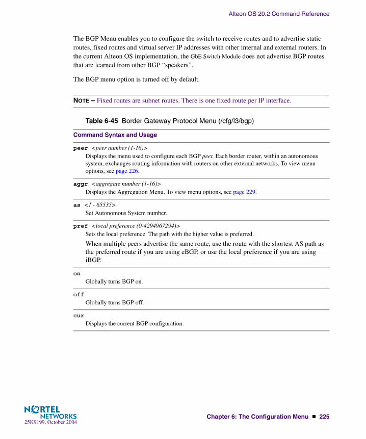
Alteon OS 20.2 Command Reference
Chapter 6: The Configuration Menu � 22525K9199, October 2004
The BGP Menu enables you to configure the switch to receive routes and to advertise static routes, fixed routes and virtual server IP addresses with other internal and external routers. In the current Alteon OS implementation, the GbE Switch Module does not advertise BGP routes that are learned from other BGP “speakers”.
The BGP menu option is turned off by default.
NOTE – Fixed routes are subnet routes. There is one fixed route per IP interface.
Table 6-45 Border Gateway Protocol Menu (/cfg/l3/bgp)
Command Syntax and Usage
peer <peer number (1-16)>Displays the menu used to configure each BGP peer. Each border router, within an autonomous system, exchanges routing information with routers on other external networks. To view menu options, see page 226.
aggr <aggregate number (1-16)>Displays the Aggregation Menu. To view menu options, see page 229.
as <1 - 65535>Set Autonomous System number.
pref <local preference (0-4294967294)>Sets the local preference. The path with the higher value is preferred.
When multiple peers advertise the same route, use the route with the shortest AS path as the preferred route if you are using eBGP, or use the local preference if you are using iBGP.
on
Globally turns BGP on.
off
Globally turns BGP off.
cur
Displays the current BGP configuration.

Alteon OS 20.2 Command Reference
226 � Chapter 6: The Configuration Menu25K9199, October 2004
/cfg/l3/bgp/peer <peer number>BGP Peer Configuration Menu
This menu is used to configure BGP peers, which are border routers that exchange routing information with routers on internal and external networks. The peer option is disabled by default.
[BGP Peer 1 Menu] redist - Redistribution menu addr - Set remote IP address ras - Set remote autonomous system number hold - Set hold time alive - Set keep alive time advert - Set min time between advertisements retry - Set connect retry interval orig - Set min time between route originations ttl - Set time-to-live of IP datagrams addi - Add rmap into in-rmap list addo - Add rmap into out-rmap list remi - Remove rmap from in-rmap list remo - Remove rmap from out-rmap list enable - Enable peer disable - Disable peer delete - Delete peer cur - Display current peer configuration
Table 6-46 BGP Peer Configuration Options (/cfg/l3/bgp/peer)
Command Syntax and Usage
redist
Displays BGP Redistribution Menu. To view the menu options, see page 228.
addr <IP address (such as 192.4.17.101)>Defines the IP address for the specified peer (border router), using dotted decimal notation. The default address is 0.0.0.0.
ras <AS number (0-65535)>Sets the remote autonomous system number for the specified peer.
hold <hold time (0, 3-65535)>Sets the period of time, in seconds, that will elapse before the peer session is torn down because the switch hasn’t received a “keep alive” message from the peer. It is set at 90 seconds by default.
alive <keepalive time (0, 1-21845)>Sets the keep-alive time for the specified peer in seconds. It is set at 0 by default.

Alteon OS 20.2 Command Reference
Chapter 6: The Configuration Menu � 22725K9199, October 2004
advert <min adv time (1-65535)>Sets time in seconds between advertisements.
retry <connect retry interval (1-65535)>Sets connection retry interval in seconds.
orig <min orig time (1-65535)>Sets the minimum time between route originations in seconds.
ttl <number of router hops (1-255)>Time-to-live (TTL) is a value in an IP packet that tells a network router whether or not the packet has been in the network too long and should be discarded. TTL specifies a certain time span in sec-onds that, when exhausted, would cause the packet to be discarded. The TTL is determined by the number of router hops the packet is allowed before it must be discarded.
This command specifies the number of router hops that the IP packet can make. This value is used to restrict the number of “hops” the advertisement makes. It is also used to support multi-hops, which allow BGP peers to talk across a routed network. The default number is set at 1.
addi <route map ID (1-32)>Adds route map into in-route map list.
addo <route map ID (1-32)>Adds route map into out-route map list.
remi <route map ID (1-32)>Removes route map from in-route map list.
remo <route map ID (1-32)>Removes route map from out-route map list.
ena
Enables this peer configuration.
dis
Disables this peer configuration.
del
Deletes this peer configuration.
cur
Displays the current BGP peer configuration.
Table 6-46 BGP Peer Configuration Options (/cfg/l3/bgp/peer)
Command Syntax and Usage
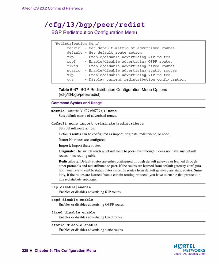
Alteon OS 20.2 Command Reference
228 � Chapter 6: The Configuration Menu25K9199, October 2004
/cfg/l3/bgp/peer/redist BGP Redistribution Configuration Menu
[Redistribution Menu] metric - Set default-metric of advertised routes default - Set default route action rip - Enable/disable advertising RIP routes ospf - Enable/disable advertising OSPF routes fixed - Enable/disable advertising fixed routes static - Enable/disable advertising static routes vip - Enable/disable advertising VIP routes cur - Display current redistribution configuration
Table 6-47 BGP Redistribution Configuration Menu Options (/cfg/l3/bgp/peer/redist)
Command Syntax and Usage
metric <metric (1-4294967294)>|noneSets default metric of advertised routes.
default none|import|originate|redistribute
Sets default route action.
Defaults routes can be configured as import, originate, redistribute, or none.
None: No routes are configured
Import: Import these routes.
Originate: The switch sends a default route to peers even though it does not have any default routes in its routing table.
Redistribute: Default routes are either configured through default gateway or learned through other protocols and redistributed to peer. If the routes are learned from default gateway configura-tion, you have to enable static routes since the routes from default gateway are static routes. Simi-larly, if the routes are learned from a certain routing protocol, you have to enable that protocol in this redistribute submenu.
rip disable|enable
Enables or disables advertising RIP routes
ospf disable|enable
Enables or disables advertising OSPF routes.
fixed disable|enable
Enables or disables advertising fixed routes.
static disable|enable
Enables or disables advertising static routes.

Alteon OS 20.2 Command Reference
Chapter 6: The Configuration Menu � 22925K9199, October 2004
/cfg/l3/bgp/aggr (aggregation number)BGP Aggregation Configuration
This menu enables you to configure filters that specify the routes/range of IP destinations a peer router will accept from other peers. A route must match a filter to be installed in the rout-ing table. By default, the first filter is enabled and the rest of the filters are disabled.
vip disable|enable
Enables or disables advertising VIP routes.
current
Displays current redistribution configuration.
[BGP Aggr 1 Menu] addr - Set aggregation IP address mask - Set aggregation network mask enable - Enable aggregation disable - Disable aggregation delete - Delete aggregation cur - Display current aggregation configuration
Table 6-48 BGP Filter Configuration Options (/cfg/l3/bgp/aggr)
Command Syntax and Usage
addr <IP address (such as 192.4.17.101)>Defines the starting IP address for this filter, using dotted decimal notation. The default address is 0.0.0.0.
mask <IP subnet mask (such as, 255.255.255.0)>This IP address mask is used with addr to define the range of IP addresses that will be accepted by the peer when the filter is enabled. The default address is 0.0.0.0.
ena
Enables this BGP filter.
dis
Disables this BGP filter.
Table 6-47 BGP Redistribution Configuration Menu Options (/cfg/l3/bgp/peer/redist)
Command Syntax and Usage

Alteon OS 20.2 Command Reference
230 � Chapter 6: The Configuration Menu25K9199, October 2004
/cfg/l3/igmpIGMP Configuration
IGMP Snooping allows the switch to forward multicast traffic only to those ports that request it. IGMP snooping prevents multicast traffic from being flooded to all ports. The switch learns which server hosts are interested in receiving multicast traffic, and forwards it only to ports connected to those servers.
del
Deletes this BGP filter.
cur
Displays the current BGP filter configuration.
[IGMP Menu] snoop - IGMP Snooping Menu mrouter - Static Multicast Router Port Menu robust - Set IGMP robustness variable qinterval - Set IGMP query interval qmrt - Set IGMP query max response time on - Globally turn IGMP ON off - Globally turn IGMP OFF cur - Display current IGMP configuration
Table 6-49 IGMP Snoop Menu (/cfg/l3/igmp)
Command Syntax and Usage
snoop
Displays the IGMP Snoop Menu. To view menu options, see page 231.
mrouter
Displays the Static Multicast Router Port Menu. To view menu options, see page 232.
robust <2-10>Configures the IGMP Robustness variable, which allows you to tune the switch for expected packet loss on the subnet. If the subnet is expected to be lossy (high rate of packet loss), increase the value. The default value is 2.
Table 6-48 BGP Filter Configuration Options (/cfg/l3/bgp/aggr)
Command Syntax and Usage

Alteon OS 20.2 Command Reference
Chapter 6: The Configuration Menu � 23125K9199, October 2004
/cfg/l3/igmp/snoopIGMP Snooping Configuration
Table 6-50 describes the commands used to configure IGMP Snooping.
qinterval <1-3600>Configures the interval for IGMP Query Reports. The default value is 125 seconds.
qmrt <1-600>Configures the maximum time allowed for IGMP Query responses from multicast routers, in tenths of a second. The default value is 100.
on
Turns IGMP on globally.
off
Turns IGMP off globally.
cur
Displays the current IGMP configuration parameters.
[IGMP Snooping Menu] mrto - Override multicast router timeout add - Add VLAN(s) to IGMP Snooping rem - Remove VLAN(s) from IGMP Snooping clear - Remove all VLAN(s) from IGMP Snooping fastlv - Enable/disable quick-leave processing in VLAN ena - Enable IGMP Snooping dis - Disable IGMP Snooping cur - Display current IGMP Snooping configuration
Table 6-50 IGMP Snoop Menu (/cfg/l3/igmp/snoop)
Command Syntax and Usage
mrto <1-255 seconds>Configures the timeout value for IGMP Membership Queries (mrouter). Once the timeout value is reached, the switch removes the multicast router from its IGMP table, if the proper conditions are met. The range is from 1 to 255 seconds. The default is 60 seconds.
add <VLAN number>Adds selected VLANs to IGMP Snooping.
Table 6-49 IGMP Snoop Menu (/cfg/l3/igmp)
Command Syntax and Usage
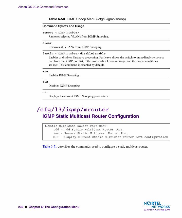
Alteon OS 20.2 Command Reference
232 � Chapter 6: The Configuration Menu25K9199, October 2004
/cfg/l3/igmp/mrouterIGMP Static Multicast Router Configuration
Table 6-51 describes the commands used to configure a static multicast router.
remove <VLAN number>Removes selected VLANs from IGMP Snooping.
clear
Removes all VLANs from IGMP Snooping.
fastlv <VLAN number> disable|enableEnables or disables Fastleave processing. Fastleave allows the switch to immediately remove a port from the IGMP port list, if the host sends a Leave message, and the proper conditions are met. This command is disabled by default.
ena
Enables IGMP Snooping.
dis
Disables IGMP Snooping.
cur
Displays the current IGMP Snooping parameters.
[Static Multicast Router Port Menu] add - Add Static Multicast Router Port rem - Remove Static Multicast Router Port cur - Display current Static Multicast Router Port configuration
Table 6-50 IGMP Snoop Menu (/cfg/l3/igmp/snoop)
Command Syntax and Usage

Alteon OS 20.2 Command Reference
Chapter 6: The Configuration Menu � 23325K9199, October 2004
NOTE – When you configure a static multicast router on a VLAN, the process of learning mul-ticast routers is disabled for that VLAN.
/cfg/l3/port <port alias or number>IP Port Configuration
The IP Port Menu allows you to turn IP forwarding on or off on a port-by-port basis. By default, the port forwarding option is turned on.
Table 6-51 IGMP Static Multicast Router Menu (/cfg/l3/igmp/static)
Command Syntax and Usage
add <port number> <VLAN number> <IGMP version number>Selects a port/VLAN combination on which the static multicast router is connected, and configures the IGMP version (1 or 2) of the multicast router. Note: Port number must be an external port.
remove <port number> <VLAN number> Removes a static multicast router from the selected port/VLAN combination.
cur
Displays the current IGMP Static Multicast Router parameters.
[IP Forwarding Port INT1 Menu] on - Turn Forwarding ON off - Turn Forwarding OFF cur - Display current port configuration
Table 6-52 IP Forwarding Port Options (/cfg/l3/port)
Command Syntax and Usage
on
Enables IP forwarding for the current port.
off
Disables IP forwarding for the current port.
cur
Displays the current IP forwarding settings.
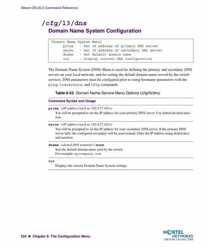
Alteon OS 20.2 Command Reference
234 � Chapter 6: The Configuration Menu25K9199, October 2004
/cfg/l3/dnsDomain Name System Configuration
The Domain Name System (DNS) Menu is used for defining the primary and secondary DNS servers on your local network, and for setting the default domain name served by the switch services. DNS parameters must be configured prior to using hostname parameters with the ping, traceroute, and tftp commands.
[Domain Name System Menu] prima - Set IP address of primary DNS server secon - Set IP address of secondary DNS server dname - Set default domain name cur - Display current DNS configuration
Table 6-53 Domain Name Service Menu Options (/cfg/l3/dns)
Command Syntax and Usage
prima <IP address (such as 192.4.17.101)>You will be prompted to set the IP address for your primary DNS server. Use dotted decimal nota-tion.
secon <IP address (such as 192.4.17.101)>You will be prompted to set the IP address for your secondary DNS server. If the primary DNS server fails, the configured secondary will be used instead. Enter the IP address using dotted deci-mal notation.
dname <dotted DNS notation>|noneSets the default domain name used by the switch. For example: mycompany.com
cur
Displays the current Domain Name System settings.

Alteon OS 20.2 Command Reference
Chapter 6: The Configuration Menu � 23525K9199, October 2004
/cfg/l3/bootpBootstrap Protocol Relay Configuration
The Bootstrap Protocol (BOOTP) Relay Menu is used to allow hosts to obtain their configura-tions from a Dynamic Host Configuration Protocol (DHCP) server. The BOOTP configuration enables the switch to forward a client request for an IP address to two DHCP/BOOTP servers with IP addresses that have been configured on the GbE Switch Module.
BOOTP relay menu is turned off by default.
[Bootstrap Protocol Relay Menu] addr - Set IP address of BOOTP server addr2 - Set IP address of second BOOTP server on - Globally turn BOOTP relay ON off - Globally turn BOOTP relay OFF cur - Display current BOOTP relay configuration
Table 6-54 Bootstrap Protocol Relay Configuration Menu Options (/cfg/l3/bootp)
Command Syntax and Usage
addr <IP address (such as, 192.4.17.101>Sets the IP address of the BOOTP server.
addr2 <IP address (such as, 192.4.17.101>>Sets the IP address of the second BOOTP server.
on
Globally turns on BOOTP relay.
off
Globally turns off BOOTP relay.
cur
Displays the current BOOTP relay configuration.

Alteon OS 20.2 Command Reference
236 � Chapter 6: The Configuration Menu25K9199, October 2004
/cfg/l3/vrrpVRRP Configuration
Virtual Router Redundancy Protocol (VRRP) support on GbE Switch Modules provides redun-dancy between routers in a LAN. This is accomplished by configuring the same virtual router IP address and ID number on each participating VRRP-capable routing device. One of the virtual routers is then elected as the master, based on a number of priority criteria, and assumes control of the shared virtual router IP address. If the master fails, one of the backup virtual routers will assume routing authority and take control of the virtual router IP address.
By default, VRRP is disabled. Alteon OS has extended VRRP to include virtual servers as well, allowing for full active/active redundancy between its Layer 4 switches. For more infor-mation on VRRP, see the “High Availability” chapter in the Alteon OS 20.2 Application Guide.
[Virtual Router Redundancy Protocol Menu] vr - VRRP Virtual Router menu group - VRRP Virtual Router Group menu if - VRRP Interface menu track - VRRP Priority Tracking menu hotstan - Enable/disable hot-standby processing trnkfo - Enable/disable trunk failover on - Globally turn VRRP ON off - Globally turn VRRP OFF cur - Display current VRRP configuration
Table 6-55 Virtual Router Redundancy Protocol Options (/cfg/l3/vrrp)
Command Syntax and Usage
vr <virtual router number (1-128)>
Displays the VRRP Virtual Router Menu. This menu is used for configuring up to 128 virtual rout-ers on this switch. To view menu options, see page 237.
group
Displays the VRRP virtual router group menu, used to combine all virtual routers together as one logical entity. Group options must be configured when using two or more Alteon switches in a hot-standby failover configuration where only one switch is active at any given time. To view menu options, see page 242.
if <interface number (1-128)>
Displays the VRRP Virtual Router Interface Menu. To view menu options, see page 246.

Alteon OS 20.2 Command Reference
Chapter 6: The Configuration Menu � 23725K9199, October 2004
/cfg/l3/vrrp/vr <router number>Virtual Router Configuration
This menu is used for configuring up to 128 virtual routers for this switch. A virtual router is defined by its virtual router ID and an IP address. On each VRRP-capable routing device par-ticipating in redundancy for this virtual router, a virtual router will be configured to share the same virtual router ID and IP address.
track
Displays the VRRP Tracking Menu. This menu is used for weighting the criteria used when modi-fying priority levels in the master router election process. To view menu options, see page 247.
hotstan disable|enable
Enables or disables hot standby processing, in which two or more switches provide redundancy for each other. By default, this option is disabled.
trnkfo disable|enable
When enabled, allows L2 Trunk Failover to be enabled when VRRP is enabled (but not hot standby processing). By default, this option is disabled.
on
Globally enables VRRP on this switch.
off
Globally disables VRRP on this switch.
cur
Displays the current VRRP parameters.
[VRRP Virtual Router 1 Menu] track - Priority Tracking Menu vrid - Set virtual router ID addr - Set IP address if - Set interface number prio - Set renter priority adver - Set advertisement interval preem - Enable or disable preemption ena - Enable virtual router dis - Disable virtual router del - Delete virtual router cur - Display current VRRP virtual router configuration
Table 6-55 Virtual Router Redundancy Protocol Options (/cfg/l3/vrrp)
Command Syntax and Usage

Alteon OS 20.2 Command Reference
238 � Chapter 6: The Configuration Menu25K9199, October 2004
Virtual routers are disabled by default.
Table 6-56 VRRP Virtual Router Options (/cfg/l3/vrrp/vr)
Command Syntax and Usage
track
Displays the VRRP Priority Tracking Menu for this virtual router. Tracking is an Alteon OS pro-prietary extension to VRRP, used for modifying the standard priority system used for electing the master router. To view menu options, see page 240.
vrid <virtual router ID (1-255)>
Defines the virtual router ID. This is used in conjunction with addr (below) to define a virtual router on this switch. To create a pool of VRRP-enabled routing devices which can provide redun-dancy to each other, each participating VRRP device must be configured with the same virtual router: one that shares the same vrid and addr combination.
The vrid for standard virtual routers (where the virtual router IP address is not the same as any virtual server) can be any integer between 1 and 255. The default value is 1.
All vrid values must be unique within the VLAN to which the virtual router’s IP interface belongs.
addr <IP address (such as, 192.4.17.101)>
Defines the IP address for this virtual router using dotted decimal notation. This is used in conjunc-tion with the vrid (above) to configure the same virtual router on each participating VRRP device. The default address is 0.0.0.0.
if <interface number (1-128)>
Selects a switch IP interface (between 1 and 128). If the IP interface has the same IP address as the addr option above, this switch is considered the “owner” of the defined virtual router. An owner has a special priority of 255 (highest) and will always assume the role of master router, even if it must preempt another virtual router which has assumed master routing authority. This preemption occurs even if the preem option below is disabled. The default value is 1.
prio <priority (1-254)>
Defines the election priority bias for this virtual server. This can be any integer between 1 and 254. The default value is 100.
During the master router election process, the routing device with the highest virtual router priority number wins. If there is a tie, the device with the highest IP interface address wins. If this virtual router’s IP address (addr) is the same as the one used by the IP interface, the priority for this vir-tual router will automatically be set to 255 (highest).
When priority tracking is used (/cfg/l3/vrrp/track or /cfg/l3/vrrp/vr #/track), this base priority value can be modified according to a number of performance and operational cri-teria.
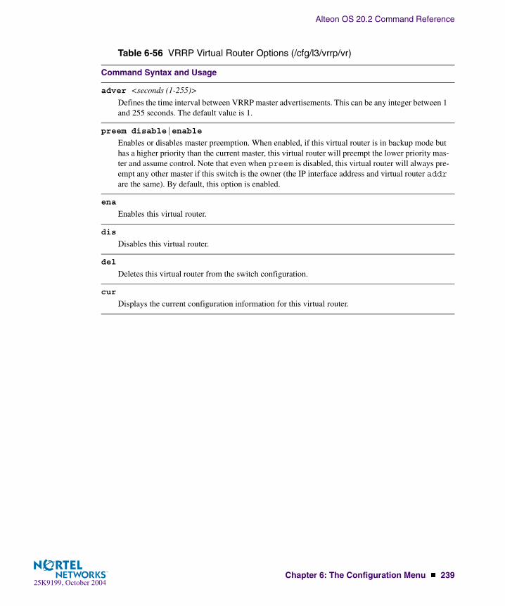
Alteon OS 20.2 Command Reference
Chapter 6: The Configuration Menu � 23925K9199, October 2004
adver <seconds (1-255)>
Defines the time interval between VRRP master advertisements. This can be any integer between 1 and 255 seconds. The default value is 1.
preem disable|enable
Enables or disables master preemption. When enabled, if this virtual router is in backup mode but has a higher priority than the current master, this virtual router will preempt the lower priority mas-ter and assume control. Note that even when preem is disabled, this virtual router will always pre-empt any other master if this switch is the owner (the IP interface address and virtual router addr are the same). By default, this option is enabled.
ena
Enables this virtual router.
dis
Disables this virtual router.
del
Deletes this virtual router from the switch configuration.
cur
Displays the current configuration information for this virtual router.
Table 6-56 VRRP Virtual Router Options (/cfg/l3/vrrp/vr)
Command Syntax and Usage

Alteon OS 20.2 Command Reference
240 � Chapter 6: The Configuration Menu25K9199, October 2004
/cfg/l3/vrrp/vr <router number>/trackVirtual Router Priority Tracking Configuration
This menu is used for modifying the priority system used when electing the master router from a pool of virtual routers. Various tracking criteria can be used to bias the election results. Each time one of the tracking criteria is met, the priority level for the virtual router is increased by an amount defined through the VRRP Tracking Menu (see page 247).
Criteria are tracked dynamically, continuously updating virtual router priority levels when enabled. If the virtual router preemption option (see preem in Table 6-56 on page 238) is enabled, this virtual router can assume master routing authority when its priority level rises above that of the current master.
Some tracking criteria (vrs, ifs, and ports below) apply to standard virtual routers, other-wise called “virtual interface routers.” Other tracking criteria (l4pts, reals, and hsrp) apply to “virtual server routers,” which perform Layer 4 Server Load Balancing functions. A virtual server router is defined as any virtual router whose IP address (addr) is the same as any configured virtual server IP address.
[VRRP Virtual Router 1 Priority Tracking Menu] vrs - Enable/disable tracking master virtual routers ifs - Enable/disable tracking other interfaces ports - Enable/disable tracking VLAN switch ports l4pts - Enable/disable tracking L4 switch ports reals - Enable/disable tracking L4 real servers hsrp - Enable/disable tracking HSRP hsrv - Enable/disable tracking HSRP by VLAN cur - Display current VRRP virtual router configuration
Table 6-57 VRRP Priority Tracking Options (/cfg/l3/vrrp/vr #/track)
Command Syntax and Usage
vrs disable|enable
When enabled, the priority for this virtual router will be increased for each virtual router in master mode on this switch. This is useful for making sure that traffic for any particular client/server pair-ing are handled by the same switch, increasing routing and load balancing efficiency. This com-mand is disabled by default.
ifs disable|enable
When enabled, the priority for this virtual router will be increased for each other IP interface active on this switch. An IP interface is considered active when there is at least one active port on the same VLAN. This helps elect the virtual routers with the most available routes as the master. This command is disabled by default.

Alteon OS 20.2 Command Reference
Chapter 6: The Configuration Menu � 24125K9199, October 2004
ports disable|enable
When enabled, the priority for this virtual router will be increased for each active port on the same VLAN. A port is considered “active” if it has a link and is forwarding traffic. This helps elect the virtual routers with the most available ports as the master. This command is disabled by default.
l4pts disable|enable
When enabled for virtual server routers, the priority for this virtual router will be increased for each physical switch port which has active Layer 4 processing on this switch. This helps elect the main Layer 4 switch as the master. This command is disabled by default.
reals disable|enable
When enabled for virtual server routers, the priority for this virtual router will be increased for each healthy real server behind the virtual server IP address of the same IP address as the virtual router on this switch. This helps elect the switch with the largest server pool as the master, increas-ing Layer 4 efficiency. This command is disabled by default.
hsrp disable|enable <priority (1-254)>Hot Standby Router Protocol (HSRP) is used with some types of routers for establishing router failover. In networks where HSRP is used, enable this switch option to increase the priority of this virtual router for each Layer 4 client-only port that receives HSRP advertisements. Enabling HSRP helps elect the switch closest to the master HSRP router as the master, optimizing routing effi-ciency. This command is disabled by default.
hsrv disable|enable
Hot Standby Router on VLAN (HSRV) is used to work in VLAN-tagged environments. Enable this switch option to increment only that vrrp instance that is on the same VLAN as the tagged hsrp master flagged packet. This command is disabled by default.
cur
Displays the current configuration for priority tracking for this virtual router.
Table 6-57 VRRP Priority Tracking Options (/cfg/l3/vrrp/vr #/track)
Command Syntax and Usage

Alteon OS 20.2 Command Reference
242 � Chapter 6: The Configuration Menu25K9199, October 2004
/cfg/l3/vrrp/groupVirtual Router Group Configuration
The Virtual Router Group menu is used for associating all virtual routers into a single logical virtual router, which forces all virtual routers on the GbE Switch Module to either be master or backup as a group. A virtual router is defined by its virtual router ID and an IP address. On each VRRP-capable routing device participating in redundancy for this virtual router, a virtual router will be configured to share the same virtual router ID and IP address.
NOTE – This option is required to be configured only when using at least two GbE Switch Mod-ules in a hot-standby failover configuration, where only one switch is active at any time.
[VRRP Virtual Router Group Menu] track - Priority Tracking Menu vrid - Set virtual router ID if - Set interface number prio - Set renter priority adver - Set advertisement interval preem - Enable or disable preemption ena - Enable virtual router dis - Disable virtual router del - Delete virtual router cur - Display current VRRP virtual router configuration
Table 6-58 VRRP Virtual Router Group Options (/cfg/l3/vrrp/group)
Command Syntax and Usage
track
Displays the VRRP Priority Tracking Menu for the virtual router group. Tracking is an Alteon OS proprietary extension to VRRP, used for modifying the standard priority system used for electing the master router. To view menu options, see page 244.
vrid <virtual router ID (1-255)>
Defines the virtual router ID.
The vrid for standard virtual routers (where the virtual router IP address is not the same as any virtual server) can be any integer between 1 and 255. All vrid values must be unique within the VLAN to which the virtual router’s IP interface (see if below) belongs. The default virtual router ID is 1.
if <interface number (1-128)>
Selects a switch IP interface (between 1 and 128). The default switch IP interface number is 1.

Alteon OS 20.2 Command Reference
Chapter 6: The Configuration Menu � 24325K9199, October 2004
prio <priority (1-254)>
Defines the election priority bias for this virtual router group. This can be any integer between 1 and 254. The default value is 100.
During the master router election process, the routing device with the highest virtual router priority number wins. If there is a tie, the device with the highest IP interface address wins. If this virtual router’s IP address (addr) is the same as the one used by the IP interface, the priority for this vir-tual router will automatically be set to 255 (highest).
When priority tracking is used (/cfg/l3/vrrp/track or /cfg/l3/vrrp/vr #/track), this base priority value can be modified according to a number of performance and operational cri-teria.
adver <seconds (1-255)>
Defines the time interval between VRRP master advertisements. This can be any integer between 1 and 255 seconds. The default is 1.
preem disable|enable
Enables or disables master preemption. When enabled, if the virtual router group is in backup mode but has a higher priority than the current master, this virtual router will preempt the lower priority master and assume control. Note that even when preem is disabled, this virtual router will always preempt any other master if this switch is the owner (the IP interface address and virtual router addr are the same). By default, this option is enabled.
ena
Enables the virtual router group.
dis
Disables the virtual router group.
del
Deletes the virtual router group from the switch configuration.
cur
Displays the current configuration information for the virtual router group.
Table 6-58 VRRP Virtual Router Group Options (/cfg/l3/vrrp/group)
Command Syntax and Usage
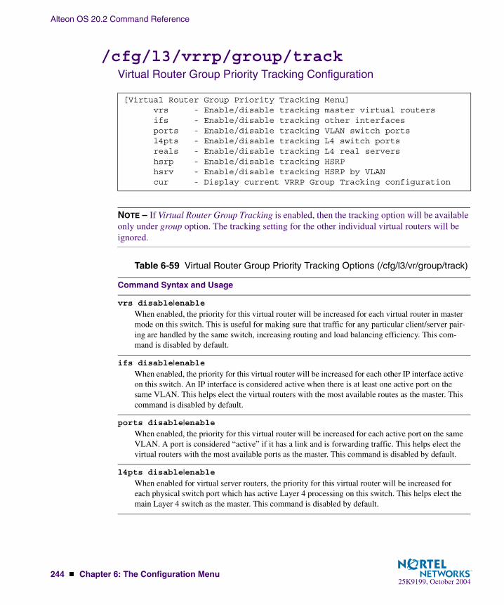
Alteon OS 20.2 Command Reference
244 � Chapter 6: The Configuration Menu25K9199, October 2004
/cfg/l3/vrrp/group/trackVirtual Router Group Priority Tracking Configuration
NOTE – If Virtual Router Group Tracking is enabled, then the tracking option will be available only under group option. The tracking setting for the other individual virtual routers will be ignored.
[Virtual Router Group Priority Tracking Menu] vrs - Enable/disable tracking master virtual routers ifs - Enable/disable tracking other interfaces ports - Enable/disable tracking VLAN switch ports l4pts - Enable/disable tracking L4 switch ports reals - Enable/disable tracking L4 real servers hsrp - Enable/disable tracking HSRP hsrv - Enable/disable tracking HSRP by VLAN cur - Display current VRRP Group Tracking configuration
Table 6-59 Virtual Router Group Priority Tracking Options (/cfg/l3/vr/group/track)
Command Syntax and Usage
vrs disable|enableWhen enabled, the priority for this virtual router will be increased for each virtual router in master mode on this switch. This is useful for making sure that traffic for any particular client/server pair-ing are handled by the same switch, increasing routing and load balancing efficiency. This com-mand is disabled by default.
ifs disable|enableWhen enabled, the priority for this virtual router will be increased for each other IP interface active on this switch. An IP interface is considered active when there is at least one active port on the same VLAN. This helps elect the virtual routers with the most available routes as the master. This command is disabled by default.
ports disable|enableWhen enabled, the priority for this virtual router will be increased for each active port on the same VLAN. A port is considered “active” if it has a link and is forwarding traffic. This helps elect the virtual routers with the most available ports as the master. This command is disabled by default.
l4pts disable|enableWhen enabled for virtual server routers, the priority for this virtual router will be increased for each physical switch port which has active Layer 4 processing on this switch. This helps elect the main Layer 4 switch as the master. This command is disabled by default.

Alteon OS 20.2 Command Reference
Chapter 6: The Configuration Menu � 24525K9199, October 2004
reals disable|enable
When enabled for virtual server routers, the priority for this virtual router will be increased for each healthy real server. This helps elect the switch with the largest server pool as the master, increasing Layer 4 efficiency. This command is disabled by default.
hsrp disable|enable
Enables Hot Standby Router Protocol (HSRP) for this virtual router group. HSRP is used with some types of routers for establishing router failover. In networks where HSRP is used, enable this switch option to increase the priority of this virtual router for each Layer 4 client-only port that receives HSRP advertisements. This helps elect the switch closest to the master HSRP router as the master, optimizing routing efficiency. This command is disabled by default.
hsrv disable|enable
Hot Standby Router on VLAN (HSRV) is used to work in VLAN-tagged environments. Enable this switch option to increment only that vrrp instance that is on the same VLAN as the tagged hsrp master flagged packet. This command is disabled by default.
cur
Displays the current configuration for priority tracking for this virtual router.
Table 6-59 Virtual Router Group Priority Tracking Options (/cfg/l3/vr/group/track)
Command Syntax and Usage

Alteon OS 20.2 Command Reference
246 � Chapter 6: The Configuration Menu25K9199, October 2004
/cfg/l3/vrrp/if <interface number>VRRP Interface Configuration
NOTE – The interface-number (1 to 128) represents the IP interface on which authentication parameters must be configured.
This menu is used for configuring VRRP authentication parameters for the IP interfaces used with the virtual routers.
[VRRP Interface 1 Menu] auth - Set authentication types passw - Set plain-text password del - Delete interface cur - Display current VRRP interface configuration
Table 6-60 VRRP Interface Menu Options (/cfg/l3/vrrp/if)
Command Syntax and Usage
auth none|password
Defines the type of authentication that will be used: none (no authentication), or password (password authentication).
passw <password>Defines a plain text password up to eight characters long. This password will be added to each VRRP packet transmitted by this interface when password authentication is chosen (see auth above).
del
Clears the authentication configuration parameters for this IP interface. The IP interface itself is not deleted.
cur
Displays the current configuration for this IP interface’s authentication parameters.

Alteon OS 20.2 Command Reference
Chapter 6: The Configuration Menu � 24725K9199, October 2004
/cfg/l3/vrrp/trackVRRP Tracking Configuration
This menu is used for setting weights for the various criteria used to modify priority levels dur-ing the master router election process. Each time one of the tracking criteria is met (see “VRRP Virtual Router Priority Tracking Menu” on page 240), the priority level for the virtual router is increased by an amount defined through this menu.
[VRRP Tracking Menu] vrs - Set priority increment for virtual router tracking ifs - Set priority increment for IP interface tracking ports - Set priority increment for VLAN switch port tracking l4pts - Set priority increment for L4 switch port tracking reals - Set priority increment for L4 real server tracking hsrp - Set priority increment for HSRP tracking hsrv - Set priority increment for HSRP by VLAN tracking cur - Display current VRRP Priority Tracking configuration
Table 6-61 VRRP Tracking Options (/cfg/l3/vrrp/track)
Command Syntax and Usage
vrs <0-254>Defines the priority increment value (1 through 254) for virtual routers in master mode detected on this switch. The default value is 2.
ifs <0-254>Defines the priority increment value (1 through 254) for active IP interfaces detected on this switch. The default value is 2.
ports <0-254>Defines the priority increment value (1 through 254) for active ports on the virtual router’s VLAN. The default value is 2.
l4pts <0-254>Defines the priority increment value (1 through 254) for physical switch ports with active Layer 4 processing. The default value is 2.
reals <0-254>Defines the priority increment value (1 through 254) for healthy real servers behind the virtual server router. The default value is 2.
hsrp <0-254>Defines the priority increment value (1 through 254) for switch ports with Layer 4 client-only pro-cessing that receive HSRP broadcasts. The default value is 10.

Alteon OS 20.2 Command Reference
248 � Chapter 6: The Configuration Menu25K9199, October 2004
NOTE – These priority tracking options only define increment values. These options do not affect the VRRP master router election process until options under the VRRP Virtual Router Priority Tracking Menu (see page 240) are enabled.
/cfg/l3/metrc <metric name>Default Gateway MetricsIf multiple default gateways are configured and enabled, a metric can be set to determine which primary gateway is selected. There are two metrics, which are described in the table .
hsrv <0-254>Defines the priority increment value (1 through 254) for vrrp instances that are on the same VLAN.
The default value is 10.
cur
Displays the current configuration of priority tracking increment values.
Table 6-62 Default Gateway Metrics (/cfg/l3/metrc)
Option Description
strict The gateway number determines its level of preference. Gateway #1 acts as the preferred default IP gateway until it fails or is disabled, at which point the next in line will take over as the default IP gateway.
roundrobin This provides basic gateway load balancing. The switch sends each new gate-way request to the next healthy, enabled gateway in line. All gateway requests to the same destination IP address are resolved to the same gateway.
Table 6-61 VRRP Tracking Options (/cfg/l3/vrrp/track)
Command Syntax and Usage
Alteon OS 20.2 Command Reference
Chapter 6: The Configuration Menu � 24925K9199, October 2004
/cfg/setupSetup
The setup program steps you through configuring the system date and time, BOOTP, IP, Span-ning Tree, port speed/mode, VLAN parameters, and IP interfaces.
To start the setup program, at the Configuration# prompt, enter:
For a complete description of how to use setup, see Chapter 2, “First-Time Configuration.”
/cfg/dumpDump
The dump program writes the current switch configuration to the terminal screen. To start the dump program, at the Configuration# prompt, enter:
The configuration is displayed with parameters that have been changed from the default val-ues. The screen display can be captured, edited, and placed in a script file, which can be used to configure other switches through a Telnet connection. When using Telnet to configure a new switch, paste the configuration commands from the script file at the command line prompt of the switch. The active configuration can also be saved or loaded via TFTP, as described on page 250.
Configuration# setup
Configuration# dump

Alteon OS 20.2 Command Reference
250 � Chapter 6: The Configuration Menu25K9199, October 2004
/cfg/ptcfg <TFTP server> <filename>Saving the Active Switch Configuration
When the ptcfg command is used, the switch’s active configuration commands (as displayed using /cfg/dump) will be uploaded to the specified script configuration file on the TFTP server. To start the switch configuration upload, at the Configuration# prompt, enter:
Where server is the TFTP server IP address or hostname, and filename is the name of the target script configuration file.
NOTE – The output file is formatted with line-breaks but no carriage returns—the file cannot be viewed with editors that require carriage returns (such as Microsoft Notepad).
NOTE – If the TFTP server is running SunOS or the Solaris operating system, the specified ptcfg file must exist prior to executing the ptcfg command and must be writable (set with proper permission, and not locked by any application). The contents of the specified file will be replaced with the current configuration data.
/cfg/gtcfg <TFTP server> <filename>Restoring the Active Switch Configuration
When the gtcfg command is used, the active configuration will be replaced with the com-mands found in the specified configuration file. The file can contain a full switch configuration or a partial switch configuration. The configuration loaded using gtcfg is not activated until the apply command is used. If the apply command is found in the configuration script file loaded using this command, the apply action will be performed automatically.
To start the switch configuration download, at the Configuration# prompt, enter:
Where server is the TFTP server IP address or hostname, and filename is the name of the target script configuration file.
Configuration# ptcfg <TFTP server> <filename>
Configuration# gtcfg <TFTP server> <filename>

25K9199, October 2004251
CHAPTER 7The SLB Configuration Menu
This chapter discusses how to use the Command Line Interface (CLI) for configuring Server Load Balancing (SLB) on the GbE Switch Module.
/cfg/slbSLB Configuration
[Layer 4 Menu] real - Real Server Menu group - Real Server Group Menu virt - Virtual Server Menu filt - Filtering Menu port - Layer 4 Port Menu layer7 - Layer 7 Resource Definition Menu wap - WAP Menu sync - Config Synch Menu adv - Layer 4 Advanced Menu advhc - Layer 4 Advanced Health Check Menu pip - Proxy IP Address Menu peerpip - Peer Proxy IP Address Menu on - Globally turn Layer 4 processing ON off - Globally turn Layer 4 processing OFF cur - Display current Layer 4 configuration
Table 7-1 Server Load Balancing Configuration Menu Options (/cfg/slb)
Command Syntax and Usage
real <real server number (1-63)>Displays the menu for configuring real servers. To view menu options, see page 254.
group <real server group number (1-64)>Displays the menu for placing real servers into real server groups. To view menu options, see page 259.
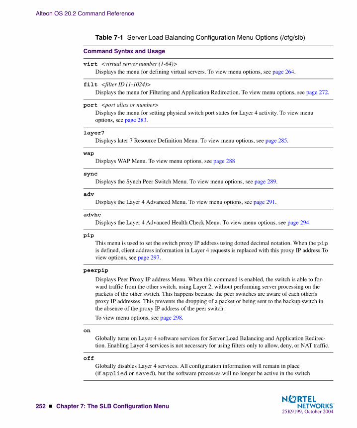
Alteon OS 20.2 Command Reference
252 � Chapter 7: The SLB Configuration Menu25K9199, October 2004
virt <virtual server number (1-64)>Displays the menu for defining virtual servers. To view menu options, see page 264.
filt <filter ID (1-1024)>Displays the menu for Filtering and Application Redirection. To view menu options, see page 272.
port <port alias or number>Displays the menu for setting physical switch port states for Layer 4 activity. To view menu options, see page 283.
layer7
Displays later 7 Resource Definition Menu. To view menu options, see page 285.
wap
Displays WAP Menu. To view menu options, see page 288
sync
Displays the Synch Peer Switch Menu. To view menu options, see page 289.
adv
Displays the Layer 4 Advanced Menu. To view menu options, see page 291.
advhc
Displays the Layer 4 Advanced Health Check Menu. To view menu options, see page 294.
pip
This menu is used to set the switch proxy IP address using dotted decimal notation. When the pip is defined, client address information in Layer 4 requests is replaced with this proxy IP address.To view options, see page 297.
peerpip
Displays Peer Proxy IP address Menu. When this command is enabled, the switch is able to for-ward traffic from the other switch, using Layer 2, without performing server processing on the packets of the other switch. This happens because the peer switches are aware of each otherís proxy IP addresses. This prevents the dropping of a packet or being sent to the backup switch in the absence of the proxy IP address of the peer switch.
To view menu options, see page 298.
on
Globally turns on Layer 4 software services for Server Load Balancing and Application Redirec-tion. Enabling Layer 4 services is not necessary for using filters only to allow, deny, or NAT traffic.
off
Globally disables Layer 4 services. All configuration information will remain in place (if applied or saved), but the software processes will no longer be active in the switch
Table 7-1 Server Load Balancing Configuration Menu Options (/cfg/slb)
Command Syntax and Usage

Alteon OS 20.2 Command Reference
Chapter 7: The SLB Configuration Menu � 25325K9199, October 2004
cur
Displays the current Server Load Balancing configuration.
Table 7-1 Server Load Balancing Configuration Menu Options (/cfg/slb)
Command Syntax and Usage

Alteon OS 20.2 Command Reference
254 � Chapter 7: The SLB Configuration Menu25K9199, October 2004
Filtering and Layer 4 (Server Load Balancing)
Filters configured to allow, deny, or perform Network Address Translation (NAT) on traffic do not require Layer 4 software to be activated. These filters are not affected by the Server Load Balancing on and off commands in this menu.
Application Redirection filters, however, require Layer 4 software services. Layer 4 processing must be turned on before redirection filters will work.
/cfg/slb/real <server number>Real Server SLB Configuration
This menu is used for configuring information about real servers that participate in a server pool for Server Load Balancing or Application Redirection. The required parameters are:
� Real server IP address
� Real server enabled (disabled by default)
[Real server 1 Menu] layer7 - Real Server Layer 7 Command Menu rip - Set IP addr of real server name - Set server name weight - Set server weight maxcon - Set maximum number of connections tmout - Set minutes inactive connection remains open backup - Set backup real server inter - Set interval between health checks retry - Set number of failed attempts to declare server DOWN restr - Set number of successful attempts to declare server UP addport - Add real port to server remport - Remove real port to server proxy - Enable/disable client proxy operation fasthc - Enable/disable fast health check operation submac - Enable/disable source MAC address substitution ena - Enable real server dis - Disable real server del - Delete real server cur - Display current real server configuration

Alteon OS 20.2 Command Reference
Chapter 7: The SLB Configuration Menu � 25525K9199, October 2004
Table 7-2 Real Server Configuration Menu Options (/cfg/slb/real)
Command Syntax and Usage
layer7
Displays the Layer 7 Menu. To view menu options, see page 258.
rip <real server IP address>Sets the IP address of the real server in dotted decimal format. When this command is used, the address entered is PINGed to determine if the server is up, and the administrator will be warned if the server does not respond.
name <string, maximum 31 characters>| noneDefines a 15-character alias for each real server. This will enable the network administrator to quickly identify the server by a natural language keyword value.
weight <real server weight (1-48)>Sets the weighting value (1 to 48) that this real server will be given in the load balancing algo-rithms. Higher weighting values force the server to receive more connections than the other servers configured in the same real server group. By default, each real server is given a weight setting of 1. A setting of 10 would assign the server roughly 10 times the number of connections as a server with a weight of 1.
Weights are not applied when using the hash or minmisses metrics (see “Server Load Balanc-ing Metrics” on page 262).
maxcon <maximum connections (0-200000)>Sets the maximum number of connections that this server should simultaneously support. By default, the number of maximum connections is set at 20,000. This option sets a threshold as an artificial barrier, such that new connections will not be issued to this server if the maxcon limit is reached. New connections will be issued again to this server once the number of current connec-tions has decreased below the maxcon setting.
If all servers in a real server group for a virtual server reach their maxcon limit at the same time, client requests will be sent to the backup/overflow server or backup/overflow server group. If no backup servers/server group are configured, client requests will be dropped by the virtual server.

Alteon OS 20.2 Command Reference
256 � Chapter 7: The SLB Configuration Menu25K9199, October 2004
tmout <even number of minutes (2-30)>Sets the number of minutes an inactive session remains open (in even numbered increments).
Every client-to-server session being load balanced is recorded in the switch’s Session Table. When a client makes a request, the session is recorded in the table, the data is transferred until the client ends the session, and the session table entry is then removed.
In certain circumstances, such as when a client application is abnormally terminated by the client’s system, TCP/UDP connections will remain registered in the switch’s binding table. In order to pre-vent table overflow, these orphaned entries must be aged out of the binding table.
Using the tmout option, you can set the number of minutes to wait before removing orphan table entries. Settings must be specified in even numbered increments between 2 and 30 minutes. The default setting is 10.
This option is also used with the Persistent option (see /cfg/slb/virt/pbind). When persis-tent is activated, this option sets how long an idle client is allowed to remain associated with a par-ticular server.
backup <real server number (1-1023)>|noneSets the real server used as the backup/overflow server for this real server.
To prevent loss of service if a particular real server fails, use this option to assign a backup real server number. Then, if the real server becomes inoperative, the switch will activate the backup real server until the original becomes operative again.
The backup server is also used in overflow situations. If the real server reaches its maxcon (maxi-mum connections) limit, the backup comes online to provide additional processing power until the original server becomes desaturated.
The same backup/overflow server may be assigned to more than one real server at the same time
inter <number of seconds between health checks (0-60)>Sets the interval between real server health verification attempts.
Determining the health of each real server is a necessary function for Layer 4 switching. For TCP services, the switch verifies that real servers and their corresponding services are operational by opening a TCP connection to each service, using the defined service ports configured as part of each virtual service. For UDP services, the switch pings servers to determine their status.
The inter option lets you choose the time between health checks. The range is from 1 to 60 sec-onds. The default interval is 2 seconds. An interval of “0” disables health checking for the server.
retry <number of consecutive health checks (1-63)>Sets the number of failed health check attempts required before declaring this real server inopera-tive. The range is from 1 to 63 attempts. The default is 4 attempts
restr <number of consecutive health checks (1-63)>Sets the number of successful health check attempts required before declaring a UDP service oper-ational. The range is from 1 to 63 attempts. The default is 8 attempts
Table 7-2 Real Server Configuration Menu Options (/cfg/slb/real)
Command Syntax and Usage
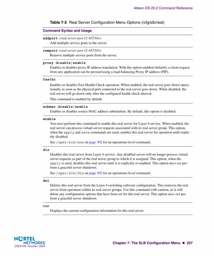
Alteon OS 20.2 Command Reference
Chapter 7: The SLB Configuration Menu � 25725K9199, October 2004
addport <real server port (2–65534)>Add multiple service ports to the server.
remport <real server port (2–65534)>Remove multiple service ports from the server.
proxy disable|enable
Enables or disables proxy IP address translation. With this option enabled (default), a client request from any application can be proxied using a load-balancing Proxy IP address (PIP).
fasthc
Enables or disables Fast Health Check operation. When enabled, the real server goes down opera-tionally as soon as the physical port connected to the real server goes down. When disabled, the real server will go down only after the configured health check interval.
This command is enabled by default.
submac disable|enable
Enables or disables source MAC address substitution. By default, this option is disabled.
enable
You must perform this command to enable this real server for Layer 4 service. When enabled, the real server can process virtual server requests associated with its real server group. This option, when the apply and save commands are used, enables this real server for operation until explic-itly disabled.
See /oper/slb/ena on page 302 for an operations-level command.
dis
Disables this real server from Layer 4 service. Any disabled server will no longer process virtual server requests as part of the real server group to which it is assigned. This option, when the apply is used, disables this real server until it is explicitly re-enabled. This option does not per-form a graceful server shutdown.
See /oper/slb/dis on page 302 for an operations-level command.
del
Deletes this real server from the Layer 4 switching software configuration. This removes the real server from operation within its real server groups. Use this command with caution, as it will delete any configuration options that have been set for this real server. This option does not per-form a graceful server shutdown.
cur
Displays the current configuration information for this real server.
Table 7-2 Real Server Configuration Menu Options (/cfg/slb/real)
Command Syntax and Usage

Alteon OS 20.2 Command Reference
258 � Chapter 7: The SLB Configuration Menu25K9199, October 2004
/cfg/slb/real <server number>/layer7Real Server Layer 7 Configuration
This menu is used for entering commands and strings for Layer 7 processing.
[Layer 7 Commands Menu] addlb - Add URL path for URL load balance remlb - Remove URL path for URL load balance cookser - Enable/disable cookie assignment server exclude - Enable/disable exclusionary string matching cur - Display current real server configuration
Table 7-3 Layer 7 Commands Menu Options (/cfg/slb/real/layer7)
Command Syntax and Usage
addlb <URL path ID [1-512]>Adds the predefined URL loadbalance string ID to the real server.
remlb <URL path ID [1-512]>Removes the predefined URL loadbalance string ID from the real server.
cookser disable|enable
Enables or disables the real server to handle client requests that don’t contain a cookie. This option is used if you want to designate a specific server to assign cookies only. This server gets the client request, assigns the cookie, and embeds the IP address of the real server that will handle the subse-quent requests from the client.�
By default, this option is disabled.
exclude disable|enable
Enables or disables exclusionary string matching. By default, this option is disabled.
cur
Displays the current real server configuration.

Alteon OS 20.2 Command Reference
Chapter 7: The SLB Configuration Menu � 25925K9199, October 2004
/cfg/slb/group <real server group number>Real Server Group SLB Configuration
This menu is used for combining real servers into real server groups. Each real server group should consist of all the real servers which provide a specific service for load balancing. Each group must consist of at least one real server. Each real server can belong to more than one group. Real server groups are used both for Server Load Balancing and Application Redirection.
[Real server group 1 Menu] metric - Set metric used to select next server in group rmetric - Set metric used to select next rport in server content - Set health check content health - Set health check type backup - Set backup real server or group name - Set real server group name realthr - Set real server failure threshold idsrprt - Set Intrusion Detection Port mhash - Set minmisses hash parameter viphlth - Enable/disable VIP health checking in DSR mode ids - Enable/disable Intrusion Detection idsfld - Enable/disable Intrusion Detection Group Flood add - Add real server rem - Remove real server del - Delete real server group cur - Display current group configuration
Table 7-4 Real Server Group Configuration Menu Options (/cfg/slb/group)
Command Syntax and Usage
metric leastconns|roundrobin|minmisses|hash|response|bandwidthSet the load balancing metric used for determining which real server in the group will be the target of the next client request. The default setting is leastconns. See “Server Load Balancing Met-rics” on page 262.
rmetric
Sets the load balancing metric used for determining which port in the real server will be the target of the next client request.
content <filename>|//<host>/<filename>|noneThis option defines the specific content which is examined during health checks. The content depends on the type of health check specified in the health option (see below).

Alteon OS 20.2 Command Reference
260 � Chapter 7: The SLB Configuration Menu25K9199, October 2004
health link|arp|icmp|tcp|http|dns|pop3|smtp|nntp|ftp|imap|radius|sslh|script<n>|udpdns|wsp|wtls|ldap
Sets the type of health checking performed. The default is tcp. The options are as follows:
link For IDSLB group only, checks status of port for each server.arp For Layer 2 health checking, sends an ARP request.icmp For Layer 3 health checking, pings the server.tcp For TCP service, opens and closes a TCP/IP connection to the server.http For HTTP service, use HTTP 1.1 GETS when a HOST: header is required to check
that the URL content is specified in content command. Otherwise, an HTTP/1.0 GET occurs. Note: If the content is not specified, the health check will revert back to TCP on the port that is being load balanced.
dns For Domain Name Service, check that the domain name specified in content can be resolved by the server.
pop3 For user mail service, check that the user:password account specified in content exists on the server.
smtp For mail-server services, check that the user specified in content is accessible on the server.
nntp For newsgroup services, check that the newsgroup name specified in content is accessible on the server.
ftp For FTP services, check that the filename specified in content is accessible on the server through anonymous login.
imap For user mail service, check that the user:password value specified in content exists on the serve
radius For RADIUS remote access server authentication, check that the user:password value specified in content exists on the GbE Switch Module and the server. To perform application health checking to a RADIUS server, the network administrator must also configure the /cfg/slb/secrt parameter. The secrt value is a field of up to 32 alphanumeric characters that is used by the switch to encrypt a password during the RSA Message Digest Algorithm (MD5) and by the RADIUS server to decrypt the password during verification.
sslh Enables the switch to query the health of the SSL servers by sending an SSL client “Hello” packet and then verify the contents of the server’s “Hello” response. During the handshake, the user and server exchange security certificates, negotiate an encryp-tion and compression method, and establish a session ID for each session.
script Enables the use of script-based health checks in send/expect format to check for appli-cation and content availability. <n> denotes the health script number (1-8).
wsp Enables connectionless WSP content health checks for WAP gateways. The content under /cfg/slb/advhc/waphc (see page 296) must also be configured.
udpdns Allows the user to perform health checking using UDP DNS queries.wtls Provides Wireless Transport Layer Security (WTLS) Hello-based health check for
encrypted and connection-oriented WTLS traffic on port 9203.ldap Sets the health check type to LDAP.
Table 7-4 Real Server Group Configuration Menu Options (/cfg/slb/group)
Command Syntax and Usage

Alteon OS 20.2 Command Reference
Chapter 7: The SLB Configuration Menu � 26125K9199, October 2004
backup r<real server number (1-64)>|g<group number>|noneSets the real server or real server group used as the backup/overflow server/server group for this real server group.
To prevent loss of service if the entire real server group fails, use this option to assign a backup real server/real server group number. Then, if the real server group becomes inoperative, the switch will activate the backup real server /server group until one of the original real servers becomes operative again.
The backup server/server group is also used in overflow situations. If all the servers in the real server group reach their maxcon (maximum connections) limit, the backup server/server group comes online to provide additional processing power until one of the original servers becomes desaturated.
The same backup/overflow server/server group may be assigned to more than one real server group at the same time.
name <string, maximum 31 characters>|noneDefines a 15-character alias for each Real Server Group. This will enable the network administra-tor to quickly identify the server group by a natural language keyword value.
realthr <real servers (1-15, 0 for disabled)> Specifies a minimum number of real servers available. If any time, the number reaches this mini-mum limit, a SYSLOG ALERT message is sent to the configured SYSLOG servers stating that the real server threshold has been reached for the concerned server load balancing group. The default threshold is 0, which also means the option is disabled
idsrprt <real server port (2-65534)>|anySets real server port for Intrusion Detection Server.
mhash 24|32 <number of sip bits used for minmisses hash>
Defines the minmisses hash parameter for this real server as either 24 or 32 bits. By default the minmiss algorithm uses the upper 24-bits of the source IP address to calculate the real server that the traffic should be sent to when the minmiss metric is selected.You can also select all 32-bits of the source IP address to hash to the real server.
viphlth disable|enable
Enables or disables VIP health checking in a service. This feature is enabled by default. However, it works only when the service has DSR (Direct Server Return) feature enabled. When viphlth is disabled, the switch uses RIP to perform all health checks, whether DSR is enabled or disabled.
ids disable|enable
Enables or disables this group of servers for IDS load balancing.
idsfld disable|enable
Enables or disables the Intrusion Detection flood.
Table 7-4 Real Server Group Configuration Menu Options (/cfg/slb/group)
Command Syntax and Usage

Alteon OS 20.2 Command Reference
262 � Chapter 7: The SLB Configuration Menu25K9199, October 2004
Server Load Balancing MetricsUsing the metric command, you can set a number of metrics for selecting which real server in a group gets the next client request. These metrics are described in the following table:
add <real server number (1-63)>Adds a real server to this real server group. You will be prompted to enter the number of the real server to add to this group.
rem <real server number (1-63)>Remove a real server from this real server group. You will be prompted for the ID number for the real server to remove from this group.
del
Deletes this real server group from the Layer 4 software configuration. This removes the group from operation under all virtual servers it is assigned to. Use this command with caution: if you remove the only group that is assigned to a virtual server, the virtual server will become inopera-tive.
cur
Displays the current configuration parameters for this real server group.
Table 7-5 Real Server Group Metrics (/cfg/slb/group/metric)
Option and Description
minmisses
Minimum misses. This metric is optimized for Application Redirection. When minmisses is specified for a real server group performing Application Redirection, all requests for a specific IP destination address will be sent to the same server. This is particularly useful in caching applica-tions, helping to maximize successful cache hits. Best statistical load balancing is achieved when the IP address destinations of load balanced frames are spread across a broad range of IP subnets.
Minmisses can also be used for Server Load Balancing. When specified for a real server group per-forming Server Load Balancing, all requests from a specific client will be sent to the same server. This is useful for applications where client information must be retained on the server between ses-sions. Server load with this metric becomes most evenly balanced as the number of active clients increases.
Table 7-4 Real Server Group Configuration Menu Options (/cfg/slb/group)
Command Syntax and Usage
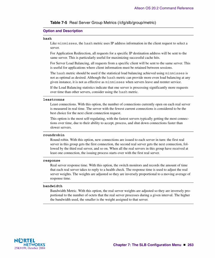
Alteon OS 20.2 Command Reference
Chapter 7: The SLB Configuration Menu � 26325K9199, October 2004
hash
Like minmisses, the hash metric uses IP address information in the client request to select a server.
For Application Redirection, all requests for a specific IP destination address will be sent to the same server. This is particularly useful for maximizing successful cache hits.
For Server Load Balancing, all requests from a specific client will be sent to the same server. This is useful for applications where client information must be retained between sessions.
The hash metric should be used if the statistical load balancing achieved using minmisses is not as optimal as desired. Although the hash metric can provide more even load balancing at any given instance, it is not as effective as minmisses when servers leave and reenter service.
If the Load Balancing statistics indicate that one server is processing significantly more requests over time than other servers, consider using the hash metric.
leastconns
Least connections. With this option, the number of connections currently open on each real server is measured in real time. The server with the fewest current connections is considered to be the best choice for the next client connection request.
This option is the most self-regulating, with the fastest servers typically getting the most connec-tions over time, due to their ability to accept, process, and shut down connections faster than slower servers.
roundrobin
Round robin. With this option, new connections are issued to each server in turn: the first real server in this group gets the first connection, the second real server gets the next connection, fol-lowed by the third real server, and so on. When all the real servers in this group have received at least one connection, the issuing process starts over with the first real server.
response
Real server response time. With this option, the switch monitors and records the amount of time that each real server takes to reply to a health check. The response time is used to adjust the real server weights. The weights are adjusted so they are inversely proportional to a moving average of response time.
bandwidth
Bandwidth Metric. With this option, the real server weights are adjusted so they are inversely pro-portional to the number of octets that the real server processes during a given interval. The higher the bandwidth used, the smaller is the weight assigned to that server.
Table 7-5 Real Server Group Metrics (/cfg/slb/group/metric)
Option and Description

Alteon OS 20.2 Command Reference
264 � Chapter 7: The SLB Configuration Menu25K9199, October 2004
NOTE – Under the leastconns and roundrobin metrics, when real servers are config-ured with weights (see the weight option on page 255), a higher proportion of connections are given to servers with higher weights. This can improve load balancing among servers of different performance levels. Weights are not applied when using the hash or minmisses metrics.
/cfg/slb/virt <virtual server number>Virtual Server SLB Configuration
This menu is used for configuring the virtual servers which will be the target for client requests for Server Load Balancing. Configuring a virtual server requires the following parameters:
� Creating a virtual server IP address
� Adding TCP/UDP port and real server group
� Enabling the virtual server (disabled by default)
[Virtual Server 1 Menu] service - Virtual Service Menu vip - Set IP addr of virtual server dname - Set domain name of virtual server layr3 - Enable/disable layer 3 only balancing ena - Enable virtual server dis - Disable virtual server del - Delete virtual server cur - Display current virtual configuration
Table 7-6 Virtual Server Configuration Menu Options (/cfg/slb/virt)
Command Syntax and Usage
service <virtual port or name>Displays the Virtual Services Menu. The virtual port name can be a well-known port name, such as http, ftp, the service number, and so on. To get more information about well-known ports, see the sport command on page 274. To view services menu options, see page 266.
vip <virtual server IP address>Sets the IP address of the virtual server using dotted-decimal notation. The virtual server created within the switch will respond to ARPs and PINGs from network ports as if it was a normal server. Client requests directed to the virtual server’s IP address will be balanced among the real servers available to it through real server group assignments.

Alteon OS 20.2 Command Reference
Chapter 7: The SLB Configuration Menu � 26525K9199, October 2004
dname <34 character domain name>|noneSets the domain name for this virtual server. The domain name typically includes the name of the company or organization, and the Internet group code (.com, .edu, .gov, .org, and so forth). An example would be foocorp.com. It does not include the hostname portion (www, www2, ftp, and so forth). The maximum number of characters that can be used in a domain name is 34. To define the hostname, see hname below. To clear the dname, specify the name as none.
layr3 disable|enable
Normally, the client IP address is used with the client Layer 4 port number to produce a session identifier. When the layr3 option is enabled (disabled by default), the switch uses only the client IP address as the session identifier. It associates all the connections from the same client with the same real server while any connection exists between them.
This option is necessary for some server applications where state information about the client sys-tem is divided across different simultaneous connections, and also in applications where TCP frag-ments are generated.
If the real server to which the client is assigned becomes unavailable, the Layer 4 software will allow the client to connect to a different server.
ena
Enables this virtual server. This option activates the virtual server within the switch so that it can service client requests sent to its defined IP address.
dis
This option disables the virtual server so that it no longer services client requests.
del
This command removes this virtual server from operation within the switch and deletes it from the Layer 4 switching software configuration. Use this command with caution, as it will delete the options that have been set for this virtual server.
cur
Displays the current configuration of the specified virtual server.
Table 7-6 Virtual Server Configuration Menu Options (/cfg/slb/virt)
Command Syntax and Usage
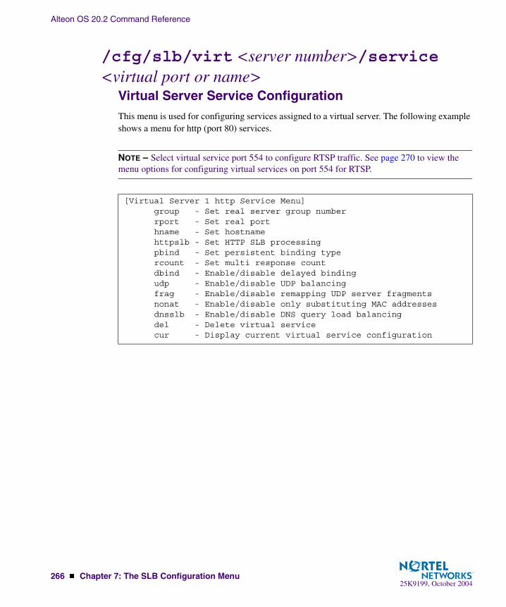
Alteon OS 20.2 Command Reference
266 � Chapter 7: The SLB Configuration Menu25K9199, October 2004
/cfg/slb/virt <server number>/service <virtual port or name>
Virtual Server Service Configuration This menu is used for configuring services assigned to a virtual server. The following example shows a menu for http (port 80) services.
NOTE – Select virtual service port 554 to configure RTSP traffic. See page 270 to view the menu options for configuring virtual services on port 554 for RTSP.
[Virtual Server 1 http Service Menu] group - Set real server group number rport - Set real port hname - Set hostname httpslb - Set HTTP SLB processing pbind - Set persistent binding type rcount - Set multi response count dbind - Enable/disable delayed binding udp - Enable/disable UDP balancing frag - Enable/disable remapping UDP server fragments nonat - Enable/disable only substituting MAC addresses dnsslb - Enable/disable DNS query load balancing del - Delete virtual service cur - Display current virtual service configuration

Alteon OS 20.2 Command Reference
Chapter 7: The SLB Configuration Menu � 26725K9199, October 2004
Table 7-7 Virtual Server Service Configuration Options (/cfg/slb/virt/service)
Command Syntax and Usage
group <real server group number (1-64)>Sets a real server group for this service. The default is set at 1. You will be prompted to enter the number (1 to 64) of the real server group to add to this service.
rport <real server port (0-65534)>Defines the real server TCP or UDP port assigned to this service. By default, this is the same as the virtual port (service virtual port). If rport is configured to be different than the virtual port defined in /cfg/slb/virt <number>/service <virtual port>, the switch will map the virtual port to this real port.
hname <hostname>|noneSets the hostname for a service added. This is used in conjunction with dname (above) to cre-ate a full host/domain name for individual services.
The format for this command is: # hname <hostname>
For example, to add a hostname for Web services, you could specify www as the hostname. If a dname of “foocorp.com” was defined (above), “www.foocorp.com” would be the full host/domain name for the service.
To clear the hostname for a service, use the command: # hname none
dbind disable|enable
Enables or disables Layer 4 Delayed Binding for TCP service and ports. Enabling this com-mand protects the server from Denial of Service (DoS) attacks. This option is disabled by default.
httpslb urlslb|host|cookie|browser|urlhash|headerhash|others|none
Load balances on the following applications:
� urlslb: Enable or disable URL SLB� host: Enable or disable for virtual hosting� cookie: Enable or disable cookie-based SLB for cookie-based preferential load balanc-
ing. You will be prompted for the following: Cookie name, starting point of the cookie value, number of bytes to be extracted, enable/disable checking for cookie in URI
� browser: Enable or disable SLB, based on browser type� urlhash: Enable or disable URL hashing based on URI� headerhash: Hashes on any HTTP header value.� others: Requires inputs for a particular header field� none: To clear all applications for httpslb, specify none.You may choose to combine or select applications to load balance using the commands and and/or or. For example:
� httpslb <application>� httpslb <application> and|or <application>
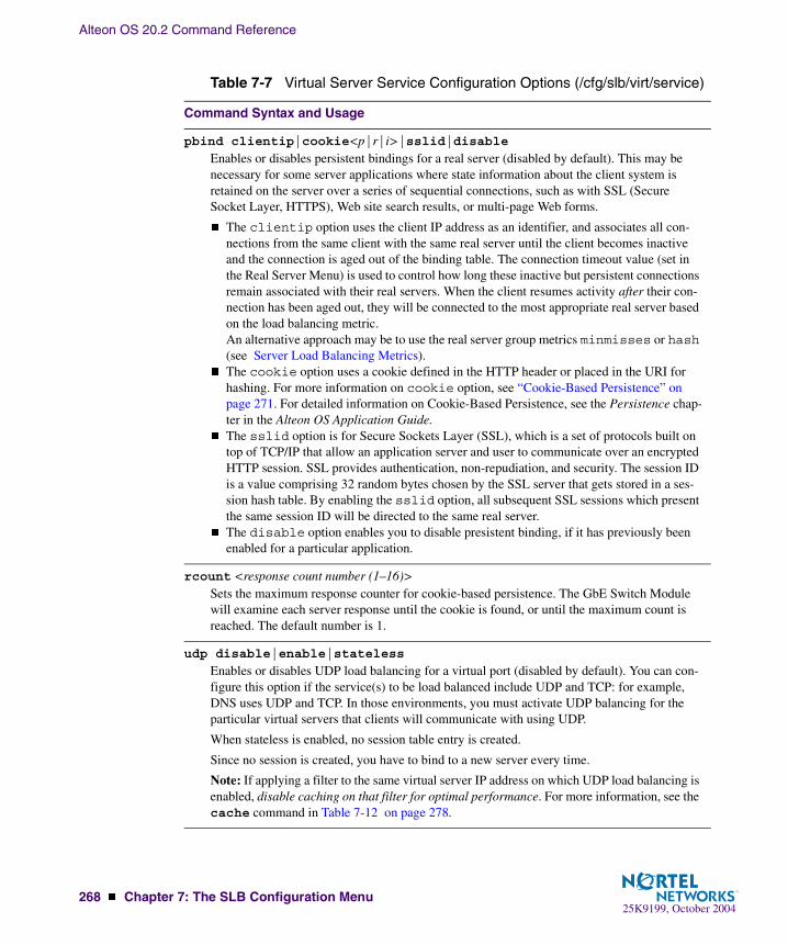
Alteon OS 20.2 Command Reference
268 � Chapter 7: The SLB Configuration Menu25K9199, October 2004
pbind clientip|cookie<p|r|i>|sslid|disableEnables or disables persistent bindings for a real server (disabled by default). This may be necessary for some server applications where state information about the client system is retained on the server over a series of sequential connections, such as with SSL (Secure Socket Layer, HTTPS), Web site search results, or multi-page Web forms.
� The clientip option uses the client IP address as an identifier, and associates all con-nections from the same client with the same real server until the client becomes inactive and the connection is aged out of the binding table. The connection timeout value (set in the Real Server Menu) is used to control how long these inactive but persistent connections remain associated with their real servers. When the client resumes activity after their con-nection has been aged out, they will be connected to the most appropriate real server based on the load balancing metric.An alternative approach may be to use the real server group metrics minmisses or hash (see Server Load Balancing Metrics).
� The cookie option uses a cookie defined in the HTTP header or placed in the URI for hashing. For more information on cookie option, see “Cookie-Based Persistence” on page 271. For detailed information on Cookie-Based Persistence, see the Persistence chap-ter in the Alteon OS Application Guide.
� The sslid option is for Secure Sockets Layer (SSL), which is a set of protocols built on top of TCP/IP that allow an application server and user to communicate over an encrypted HTTP session. SSL provides authentication, non-repudiation, and security. The session ID is a value comprising 32 random bytes chosen by the SSL server that gets stored in a ses-sion hash table. By enabling the sslid option, all subsequent SSL sessions which present the same session ID will be directed to the same real server.
� The disable option enables you to disable presistent binding, if it has previously been enabled for a particular application.
rcount <response count number (1–16)>Sets the maximum response counter for cookie-based persistence. The GbE Switch Module will examine each server response until the cookie is found, or until the maximum count is reached. The default number is 1.
udp disable|enable|stateless
Enables or disables UDP load balancing for a virtual port (disabled by default). You can con-figure this option if the service(s) to be load balanced include UDP and TCP: for example, DNS uses UDP and TCP. In those environments, you must activate UDP balancing for the particular virtual servers that clients will communicate with using UDP.
When stateless is enabled, no session table entry is created.
Since no session is created, you have to bind to a new server every time.
Note: If applying a filter to the same virtual server IP address on which UDP load balancing is enabled, disable caching on that filter for optimal performance. For more information, see the cache command in Table 7-12 on page 278.
Table 7-7 Virtual Server Service Configuration Options (/cfg/slb/virt/service)
Command Syntax and Usage

Alteon OS 20.2 Command Reference
Chapter 7: The SLB Configuration Menu � 26925K9199, October 2004
frag disable|enable
Enables or disables remapping server fragments for virtual port. This option is enabled by default.
nonat disable|enable
Enables or disables substituting only the MAC address of the real server (disabled by default). This option does not substitute IP addresses. This option is used for Direct Server Return (DSR) in an one-armed load balancing setup, so that frames returning from server to the client do not have to pass through the switch.
dnsslb disable|enable
Enables or disables DNS-based Layer 7 content load balancing.
del
This command removes this virtual service from operation within the switch and deletes it from the Layer 4 switching software configuration. Use this command with caution, as it will delete the options that have been set for this virtual service.
cur
Displays the current configuration of services on the specified virtual server.
Table 7-7 Virtual Server Service Configuration Options (/cfg/slb/virt/service)
Command Syntax and Usage

Alteon OS 20.2 Command Reference
270 � Chapter 7: The SLB Configuration Menu25K9199, October 2004
/cfg/slb/virt <server number>/service 554Virtual Server RTSP ConfigurationThis menu displays virtual services configured on service port 554 for RTSP traffic. See “/cfg/slb/virt <server number>/service <virtual port or name>” on page 266 to view the menu options for configuring virtual services on port 80.
[Virtual Server 1 rtsp Service Menu] group - Set real server group number hname - Set hostname rtspslb - Set RTSP URL load balancing type del - Delete virtual service cur - Display current virtual service configuration
Table 7-8 Virtual Server Service Configuration Menu Options(/cfg/slb/virt 1/service 554)
Command Syntax and Usage
group <real server group number (1-64)>Sets real server group number.
hname
Sets the hostname for a service added. This is used in conjunction with dname (above) to create a full host/domain name for individual services.
The format for this command is: # hname <hostname>
For example, to add a hostname for Web services, you could specify www as the hostname. If a dname of “foocorp.com” was defined (above), “www.foocorp.com” would be the full host/domain name for the service.
To clear the hostname for a service, use the command: # hname none
rtspslb hash|patternMatch|disable
This Layer 7 load balancing option sets the type of rtspslb (hash|patternMatch, thereby enabling the service), or disables rtspslb service altogether with disable command.
To enable Layer 7 load balancing for RTSP service, group must be configured under the menu /cfg/slb/virt <virtual server number>/service 80. If you don’t configure group, ser-vice 80 and service RTSP will load balance the default group, which is group 1. See command group in the table “Virtual Server Service Configuration Options (/cfg/slb/virt/service)” on page 267 for details on how to configure group.
del
Deletes this virtual service.
cur
Displays the current virtual service configuration.
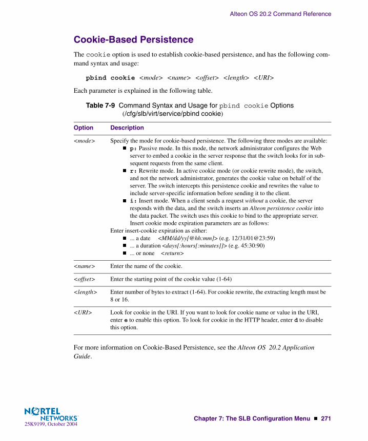
Alteon OS 20.2 Command Reference
Chapter 7: The SLB Configuration Menu � 27125K9199, October 2004
Cookie-Based PersistenceThe cookie option is used to establish cookie-based persistence, and has the following com-mand syntax and usage:
pbind cookie <mode> <name> <offset> <length> <URI>
Each parameter is explained in the following table.
For more information on Cookie-Based Persistence, see the Alteon OS 20.2 Application Guide.
Table 7-9 Command Syntax and Usage for pbind cookie Options (/cfg/slb/virt/service/pbind cookie)
Option Description
<mode> Specify the mode for cookie-based persistence. The following three modes are available:� p: Passive mode. In this mode, the network administrator configures the Web
server to embed a cookie in the server response that the switch looks for in sub-sequent requests from the same client.
� r: Rewrite mode. In active cookie mode (or cookie rewrite mode), the switch, and not the network administrator, generates the cookie value on behalf of the server. The switch intercepts this persistence cookie and rewrites the value to include server-specific information before sending it to the client.
� i: Insert mode. When a client sends a request without a cookie, the server responds with the data, and the switch inserts an Alteon persistence cookie into the data packet. The switch uses this cookie to bind to the appropriate server.Insert cookie mode expiration parameters are as follows:
Enter insert-cookie expiration as either:� ... a date <MM/dd/yy[@hh:mm]> (e.g. 12/31/01@23:59)� ... a duration <days[:hours[:minutes]]> (e.g. 45:30:90)� ... or none <return>
<name> Enter the name of the cookie.
<offset> Enter the starting point of the cookie value (1-64)
<length> Enter number of bytes to extract (1-64). For cookie rewrite, the extracting length must be 8 or 16.
<URI> Look for cookie in the URI. If you want to look for cookie name or value in the URI, enter e to enable this option. To look for cookie in the HTTP header, enter d to disable this option.
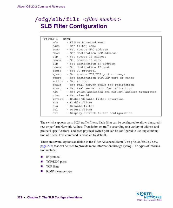
Alteon OS 20.2 Command Reference
272 � Chapter 7: The SLB Configuration Menu25K9199, October 2004
/cfg/slb/filt <filter number>SLB Filter Configuration
The switch supports up to 1024 traffic filters. Each filter can be configured to allow, deny, redi-rect or perform Network Address Translation on traffic according to a variety of address and protocol specifications, and each physical switch port can be configured to use any combina-tion of filters. This command is disabled by default.
There are several options available in the Filter Advanced Menu (/cfg/slb/filt/adv, page 277) that can be used to provide more information through syslog. The types of informa-tion include:
� IP protocol
� TCP/UDP ports
� TCP flags
� ICMP message type
[Filter 1 Menu] adv - Filter Advanced Menu name - Set filter name smac - Set source MAC address dmac - Set destination MAC address sip - Set source IP address smask - Set source IP mask dip - Set destination IP address dmask - Set destination IP mask proto - Set IP protocol sport - Set source TCP/UDP port or range dport - Set destination TCP/UDP port or range action - Set action group - Set real server group for redirection rport - Set real server port for redirection nat - Set which addresses are network address translated vlan - Set vlan id invert - Enable/disable filter inversion ena - Enable filter dis - Disable filter del - Delete filter cur - Display current filter configuration

Alteon OS 20.2 Command Reference
Chapter 7: The SLB Configuration Menu � 27325K9199, October 2004
The following parameters are required for filtering:
� Set the address, masks, and/or protocol that will be affected by the filter
� Set the filter action (allow, deny, redirect, nat)
� Enable the filter
� Add the filter to a switch port
� Enable filtering on the GbE Switch Module port
Table 7-10 Filter Configuration Menu Options (/cfg/slb/filt)
Command Syntax and Usage
adv
Displays the Filter Advanced Menu. To view menu options, see page 277.
name <31 character name>|noneAllows the user to assign a name to a filter.
smac <MAC address (such as, 00:60:cf:40:56:00)>|anySets the source MAC address. The default is any.
dmac <MAC address (such as, 00:60:cf:40:56:00)>|anySets the destination MAC address. The default is any.
sip <IP address>|anyIf defined, traffic with this source IP address will be affected by this filter. Specify an IP address in dotted decimal notation, or any. A range of IP addresses is produced when used with the smask below. The default is any if the source MAC address is any.
smask <<IP subnet mask (such as, 255.255.255.0>This IP address mask is used with the sip to select traffic which this filter will affect. See details below for more information on producing address ranges. For more information, see “Defining IP Address Ranges for Filters” on page 276.
dip <IP address>|anyIf defined, traffic with this destination IP address will be affected by this filter. Specify an IP address in dotted decimal notation, or any. A range of IP addresses is produced when used with the dmask below. The default is any if the destination MAC address is any. For more information, see “Defining IP Address Ranges for Filters” on page 276.
dmask <IP subnet mask (such as, 255.255.255.0)>This IP address mask is used with the dip to select traffic which this filter will affect.

Alteon OS 20.2 Command Reference
274 � Chapter 7: The SLB Configuration Menu25K9199, October 2004
proto <number>|<name>|anyIf defined, traffic from the specified protocol is affected by this filter. Specify the protocol number, name, or “any”. The default is any. Listed below are some of the well-known proto-cols.
Number Name1 icmp2 igmp6 tcp17 udp89 ospf112 vrrp
sport <name>|<port>|<port>-<port>|anyIf defined, traffic with the specified TCP or UDP source port will be affected by this filter. Specify the port number, range, name, or “any”. The default is any. Listed below are some of the well-known ports::
Number Name20 ftp-data21 ftp22 ssh23 telnet25 smtp37 time42 name43 whois53 domain69 tftp70 gopher79 finger80 http109 pop2110 pop3
dport <name>|<port>|<port>-<port>|anyIf defined, traffic with the specified real server TCP or UDP destination port will be affected by this filter. Specify the port number, range, name, or “any”, just as with sport above. The default is set at any.
Table 7-10 Filter Configuration Menu Options (/cfg/slb/filt)
Command Syntax and Usage
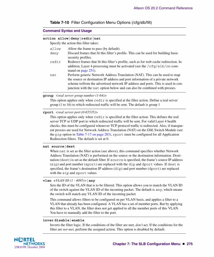
Alteon OS 20.2 Command Reference
Chapter 7: The SLB Configuration Menu � 27525K9199, October 2004
action allow|deny|redir|nat
Specify the action this filter takes:
allow Allow the frame to pass (by default).deny Discard frames that fit this filter’s profile. This can be used for building basic
security profiles.redir Redirect frames that fit this filter’s profile, such as for web cache redirection. In
addition, Layer 4 processing must be activated (see the /cfg/slb/on com-mand on page 251).
nat Perform generic Network Address Translation (NAT). This can be used to map the source or destination IP address and port information of a private network scheme to/from the advertised network IP address and ports. This is used in con-junction with the nat option below and can also be combined with proxies.
group <real server group number (1-64)>This option applies only when redir is specified at the filter action. Define a real server group (1 to 16) to which redirected traffic will be sent. The default is group 1
rport <real server port (0-65535)>This option applies only when redir is specified at the filter action. This defines the real server TCP or UDP port to which redirected traffic will be sent. For valid Layer 4 health checks, this must be configured whenever TCP protocol traffic is redirected. Also, if transpar-ent proxies are used for Network Address Translation (NAT) on the GbE Switch Module (see the pip option in Table 7-17 on page 283), rport must be configured for all Application Redirection filters. The default is set at 0.
nat source|dest
When nat is set as the filter action (see above), this command specifies whether Network Address Translation (NAT) is performed on the source or the destination information. Desti-nation (dest) is set as the default filter. If source is specified, the frame’s source IP address (sip) and port number (sport) are replaced with the dip and dport values. If dest is specified, the frame’s destination IP address (dip) and port number (dport) are replaced with the sip and sport values.
vlan <VLAN ID (1 - 4095)>|anySets the ID of the VLAN that is to be filtered. This option allows you to match the VLAN ID of the switch against the VLAN ID of the incoming packet. The default is any, which means the switch will match any VLAN ID of the incoming packet
This command allows filters to be configured on per VLAN basis, and applies a filter to a VLAN that already has been configured. A VLAN has a set of member ports. But by applying this filter to a VLAN, the filter does not get applied to all the member ports of this VLAN. You have to manually add the filter to the port.
inver disable|enableInverts the filter logic. If the conditions of the filter are met, don’t act. If the conditions for the filter are not met, perform the assigned action. This option is disabled by default.
Table 7-10 Filter Configuration Menu Options (/cfg/slb/filt)
Command Syntax and Usage

Alteon OS 20.2 Command Reference
276 � Chapter 7: The SLB Configuration Menu25K9199, October 2004
Defining IP Address Ranges for FiltersYou can specify a range of IP address for filtering both the source and/or destination IP address for traffic. When a range of IP addresses is needed, the sip (source) or dip (destination) defines the base IP address in the desired range, and the smask (source) or dmask (destina-tion) is the mask which is applied to produce the range.
For example, to determine if a client request’s destination IP address should be redirected to the cache servers attached to a particular switch, the destination IP address is masked (bitwise AND) with the dmask and then compared to the dip.
As another example, you could configure the switch with two filters so that each would handle traffic filtering for one half of the Internet. To do this, you could define the following parame-ters:
ena
Enables this filter.
dis
Disables this filter.
del
Deletes this filter.
cur
Displays the current configuration of the filter.
Table 7-11 Filtering IP Address Ranges
Filter Internet Address Range dip dmask
#1 0.0.0.0 - 127.255.255.255 0.0.0.0 128.0.0.0
#2 128.0.0.0 - 255.255.255.255 128.0.0.0 128.0.0.0
Table 7-10 Filter Configuration Menu Options (/cfg/slb/filt)
Command Syntax and Usage
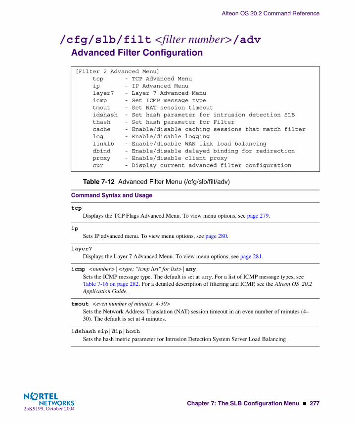
Alteon OS 20.2 Command Reference
Chapter 7: The SLB Configuration Menu � 27725K9199, October 2004
/cfg/slb/filt <filter number>/advAdvanced Filter Configuration
[Filter 2 Advanced Menu] tcp - TCP Advanced Menu ip - IP Advanced Menu layer7 - Layer 7 Advanced Menu icmp - Set ICMP message type tmout - Set NAT session timeout idshash - Set hash parameter for intrusion detection SLB thash - Set hash parameter for Filter cache - Enable/disable caching sessions that match filter log - Enable/disable logging linklb - Enable/disable WAN link load balancing dbind - Enable/disable delayed binding for redirection proxy - Enable/disable client proxy cur - Display current advanced filter configuration
Table 7-12 Advanced Filter Menu (/cfg/slb/filt/adv)
Command Syntax and Usage
tcp
Displays the TCP Flags Advanced Menu. To view menu options, see page 279.
ip
Sets IP advanced menu. To view menu options, see page 280.
layer7
Displays the Layer 7 Advanced Menu. To view menu options, see page 281.
icmp <number>|<type; "icmp list" for list>|anySets the ICMP message type. The default is set at any. For a list of ICMP message types, see Table 7-16 on page 282. For a detailed description of filtering and ICMP, see the Alteon OS 20.2 Application Guide.
tmout <even number of minutes, 4-30>Sets the Network Address Translation (NAT) session timeout in an even number of minutes (4–30). The default is set at 4 minutes.
idshash sip|dip|bothSets the hash metric parameter for Intrusion Detection System Server Load Balancing
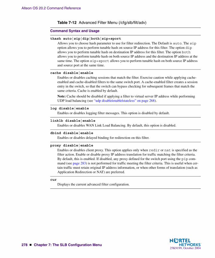
Alteon OS 20.2 Command Reference
278 � Chapter 7: The SLB Configuration Menu25K9199, October 2004
thash auto|sip|dip|both|sip+sport
Allows you to choose hash parameter to use for filter redirection. The Default is auto. The sip option allows you to perform tunable hash on source IP address for this filter. The option dip allows you to perform tunable hash on destination IP address for this filter. The option both allows you to perform tunable hash on both source IP address and the destination IP address at the same time. The option sip+sport allows you to perform tunable hash on both source IP address and source port at the same time.
cache disable|enable
Enables or disables caching sessions that match the filter. Exercise caution while applying cache-enabled and cache-disabled filters to the same switch port. A cache-enabled filter creates a session entry in the switch, so that the switch can bypass checking for subsequent frames that match the same criteria. Cache is enabled by default.
Note: Cache should be disabled if applying a filter to virtual server IP address while performing UDP load balancing (see “udp disable|enable|stateless” on page 268).
log disable|enable
Enables or disables logging filter messages. This option is disabled by default.
linklb disable|enable
Enables or disables WAN Link Load Balancing. By default, this option is disabled.
dbind disable|enable
Enables or disables delayed binding for redirection on this filter.
proxy disable|enable
Enables or disables client proxy. This option applies only when redir or nat is specified as the filter action. Enable or disable proxy IP address translation for traffic matching the filter criteria. By default, this is enabled. If disabled, any proxy defined for the switch port using the pip com-mand (see page 283) is not performed for traffic meeting the filter criteria. This is useful when cer-tain traffic must retain original IP address information, or when other forms of translation (such as Application Redirection or NAT) are preferred.
cur
Displays the current advanced filter configuration.
Table 7-12 Advanced Filter Menu (/cfg/slb/filt/adv)
Command Syntax and Usage

Alteon OS 20.2 Command Reference
Chapter 7: The SLB Configuration Menu � 27925K9199, October 2004
/cfg/slb/filt <filter number>/adv/tcpAdvanced Filter TCP Configuration
These commands can be used to configure packet filtering for specific TCP flags.
[TCP advanced menu Menu] urg - Enable/disable TCP URG matching ack - Enable/disable TCP ACK matching psh - Enable/disable TCP PSH matching rst - Enable/disable TCP RST matching syn - Enable/disable TCP SYN matching fin - Enable/disable TCP FIN matching ackrst - Enable/disable TCP ACK or RST matching tcplim - Enable/disable TCP connection rate limiting maxconn - Set maximum connections for TCP rate limiting cur - Display current TCP configuration
Table 7-13 Advanced Filter TCP Menu (/cfg/slb/filt/adv/tcp)
Command Syntax and Usage
urg disable|enable
Enables or disables TCP URG (urgent) flag matching. By default, this option is disabled.
ack disable|enable
Enables or disables TCP ACK (acknowledgement) flag matching. By default, this option is dis-abled.
psh disable|enable
Enables or disables TCP PSH (push) flag matching. By default, this option is disabled.
rst disable|enable
Enables or disables TCP RST (reset) flag matching. By default, this option is disabled.
syn disable|enable
Enables or disables TCP SYN (synchronize) flag matching. By default, this option is disabled.
fin disable|enable
Enables or disables TCP FIN (finish) flag matching. By default, this option is disabled.
ackrst disable|enable
Enables or disables TCP acknowledgement or reset flag matching. By default, this option is disabled.
tcplim disable|enable
Enables or disables TCP connection rate limiting. By default, this option is disabled.

Alteon OS 20.2 Command Reference
280 � Chapter 7: The SLB Configuration Menu25K9199, October 2004
/cfg/slb/filt <filter number> /adv/ipIP Advanced Menu
maxconn <number of connections in units of 10 (0-255)>Sets the maximum limit for new TCP connections in units of 10. To set the maximum number of connections (2,550), enter 250. To set the minimum number of connections (10, from the same user), enter 1.
The default is 10 (100 connections).
cur
Displays the current Access Control List TCP filter configuration.
[IP advanced menu] tos - Set IP Type of Service tmask - Set IP TOS mask newtos - Set new IP TOS option - Enable/disable IP option matching cur - Display current IP configuration
Table 7-14 IP Advanced Menu Options (/cfg/slb/filt #/adv/ip)
Command Syntax and Usage
tos <0-255>Sets IP type of service (ToS) and the value of the type of service. For more information on ToS, refer to RFC 1340 and 1349.
tmask <0-255>Sets IP type of service mask.
newtos <0-255>Sets new IP type of service.
option disable|enable
Enables or disables IP option matching.
cur
Displays current advanced IP settings for the selected filter.
Table 7-13 Advanced Filter TCP Menu (/cfg/slb/filt/adv/tcp)
Command Syntax and Usage

Alteon OS 20.2 Command Reference
Chapter 7: The SLB Configuration Menu � 28125K9199, October 2004
/cfg/slb/filt <filter number> /adv/layer7Layer 7 Advanced Menu
[Layer 7 Advanced Menu] addstr - Add string for layer 7 filtering remstr - Remove string for layer 7 filtering rdsnp - Enable/disable WAP RADIUS Snooping ftpa - Enable/disable active FTP NAT l7lkup - Enable/disable Layer 7 content lookup cur - Display current layer 7 configuration
Table 7-15 Layer 7 Advanced Menu Options (/cfg/slb/filt #/adv/layer7)
Command Syntax and Usage
addstr <string id (1-512)>Adds the string ID to this filter for L7 filtering. The string is defined under: /cfg/slb/layer7/slb/add.
remstr <string id (1-512)>Removes the string ID for Layer 7 filtering. The string is defined under: /cfg/slb/layer7/slb/add.
rdsnp disable|enable
Enables or disables WAP RADIUS Snooping capability of a filter. By default, this option is dis-abled.
ftpa disable|enable
Enables or disables active FTP Client Network Address Translation (NAT). When a client in active FTP mode sends a PORT command to a remote FTP server, the switch will look into the data part of the frame and replace the client ’s private IP address with a proxy IP (PIP) address. The real server port (RPORT) will be replaced with a proxy port (PPORT), that is PIP:PPORT. By default, this option is disabled.
l7lkup
Enable/disable Layer 7 content lookup.
cur
Displays current advanced Layer 7 settings for the selected filter.

Alteon OS 20.2 Command Reference
282 � Chapter 7: The SLB Configuration Menu25K9199, October 2004
ICMP Message Types
The following ICMP message types are used with the /cfg/slb/filt/adv/icmp com-mand. You can list all ICMP message types with the /cfg/slb/filt/adv/icmp list command.
Table 7-16 ICMP Message Types
Type # Message Type Description
0 echorep ICMP echo reply
3 destun ICMP destination unreachable
4 quench ICMP source quench
5 redir ICMP redirect
8 echoreq ICMP echo request
9 rtradv ICMP router advertisement
10 rtrsol ICMP router solicitation
11 timex ICMP time exceeded
12 param ICMP parameter problem
13 timereq ICMP timestamp request
14 timerep ICMP timestamp reply
15 inforeq ICMP information request
16 inforep ICMP information reply
17 maskreq ICMP address mask request
18 maskrep ICMP address mask reply

Alteon OS 20.2 Command Reference
Chapter 7: The SLB Configuration Menu � 28325K9199, October 2004
/cfg/slb/port <port alias or number>Port SLB Configuration
Alteon OS switch software allows you to enable or disable processing independently for each type of Layer 4 traffic (client and server) on a per port basis, expanding your topology options.
NOTE – When changing the filters on a given port, it may take some time before the port ses-sion information is updated so that the filter changes take effect. To make port filter changes take effect immediately, clear the session binding table for the port (see the clear command in Table 8-3 on page 302).
[SLB port INT1 Menu] client - Enable/disable client processing server - Enable/disable server processing rts - Enable/disable RTS processing hotstan - Enable/disable hot-standby processing intersw - Enable/disable inter-switch processing proxy - Enable/disable use of PIP for ingress traffic filt - Enable/disable filtering add - Add filter to port rem - Remove filter from port idslb - Enable/disable intrusion detection server load balancing cur - Display current port configuration
Table 7-17 Port Configuration Menu Options (/cfg/slb/port)
Command Syntax and Usage
client disable|enable
For Server Load Balancing, the port can be enabled or disabled to process client Layer 4 traffic. Ports configured to process client request traffic bind servers to clients and provide address translation from the virtual server IP address to the real server IP address, re-mapping virtual server IP addresses and port values to real server IP addresses and ports. Traffic not associated with virtual servers is switched normally. Maximizing the number of these ports on the Layer 4 switch will improve the switch’s potential for effective Server Load Balancing. This option is disabled by default.
server disable|enable
Ports configured to provide real server responses to client requests require real servers to be con-nected to the Layer 4 switch, directly or through a hub, router, or another switch. When server pro-cessing is enabled, the switch port re-maps real server IP addresses and Layer 4 port values to virtual server IP addresses and Layer 4 ports. Traffic not associated with virtual servers is switched normally. This option is disabled by default.

Alteon OS 20.2 Command Reference
284 � Chapter 7: The SLB Configuration Menu25K9199, October 2004
rts disable|enable
Enables or disables Return to Sender (RTS) load balancing on this port. This option is used for firewall load balancing or VPN load balancing applications. Enable rts on all client-side ports to ensure that traffic ingresses and egresses through the same port. This option is disabled by default.
For more information on using rts, see the “Firewall Load Balancing” and “VPN Load Balanc-ing” chapters in the Alteon OS 20.2 Application Guide.
hotstan disable|enable
Enables or disables hot-standby processing. Use this option and the intersw option in conjunc-tion with VRRP hot-standby failover. This option is disabled by default.
intersw disable|enable
Enables or disables inter-switch processing. This option is enabled for ports connected to a peer switch and is disabled by default.
proxy disable|enable
Enables or disables a proxy for traffic that ingresses this port. When the PIP is defined, client address information in Layer 4 requests is replaced with this proxy IP address.
In Server Load Balancing applications, this forces response traffic to return through the switch, rather than around it, as is possible in complex routing environments.
Proxies are also useful for Application Redirection and Network Address Translation (NAT). When pip is used with Application Redirection filters, each filter’s rport parameter must also be defined (see rport on page 273). This option is disabled by default.
filt disable|enable
Enables or disables filtering on this port. Enabling the filter sets up the Real Server to look into the VPN session table. This option is disabled by default.
add <filter ID (1 to 1024)|block of IDs (first-last)>Adds a filter or a block of filters for use on this port. Enter filter ID (1 to 1024) or a contiguous block of filter IDs. For example, 1-100.
rem <filter ID (1 to 1024)|block of IDs (first-last)>Removes a filter or a block of filters from use on this port. Enter filter ID (1 to 1024) or a contiguous block of filter IDs. For example, 1-100.
idslb disable|enable
Enables or disables Intrusion Detection System Server Load Balancing for this port. This option is disabled by default.
cur
Displays current system parameters.
Table 7-17 Port Configuration Menu Options (/cfg/slb/port)
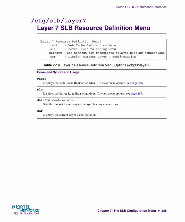
Alteon OS 20.2 Command Reference
Chapter 7: The SLB Configuration Menu � 28525K9199, October 2004
/cfg/slb/layer7Layer 7 SLB Resource Definition Menu
[Layer 7 Resource Definition Menu] redir - Web Cache Redirection Menu slb - Server Load Balancing Menu dbindtm - Set timeout for incomplete delayed binding connections cur - Display current Layer 7 configuration
Table 7-18 Layer 7 Resource Definition Menu Options (/cfg/slb/layer7)
Command Syntax and Usage
redir
Displays the Web Cache Redirection Menu. To view menu options, see page 286.
slb
Displays the Server Load Balancing Menu. To view menu options, see page 287.
dbindtm <10-60 seconds>Sets the timeout for incomplete delayed binding connections.
cur
Displays the current Layer 7 configuration.

Alteon OS 20.2 Command Reference
286 � Chapter 7: The SLB Configuration Menu25K9199, October 2004
/cfg/slb/layer7/redirWeb Cache Redirection Configuration
[Web Cache Redirection Menu] urlal - Enable/disable auto-ALLOW for non-GETs to origin servers cookie - Enable/disable auto-ALLOW for Cookie to origin servers nocache - Enable/disable no-cache control header to origin servers hash - Enable/disable URL hashing based on URI header - Enable/disable server loadbalance based on HTTP header cur - Display current WCR configuration
Table 7-19 Web Cache Redirection Menu Options (/cfg/slb/layer7/redir)
Command Syntax and Usage
urlal disable|enable
Enables or disables auto-ALLOW for non-GETs to origin servers.
� If this command is enabled, the switch will redirect all non-GET requests to the origin server.� If this command is disabled, the switch will compare the URI against the expression table to
determine whether all non-GET requests should be redirected to a cache server or origin server.This option is enabled by default.
cookie disable|enable
Enables or disables auto-ALLOW for cookie to origin servers.
� If this command is enabled, the switch will redirect all requests that contain Cookie: in the HTTP header to the origin server.
� If this command is disabled, the switch will compare the URI against the expression table to determine whether it should redirect all requests that contain Cookie: in the HTTP header to a cache server or origin server.
This option is disabled by default.
nocache disable|enable
Enables or disables no-cache control header to origin servers.
� If this command is enabled, the switch will redirect all requests that contain Cache-Control: no-cache in HTTP/1.1 header, or Pragma: no-cache in HTTP/1.0 header to the origin server.
� If this command is disabled, the switch will compare the URI against the expression table to determine whether it should redirect requests that contain Cache-Control: no-cache in HTTP/1.1 header, or Pragma: no-cache in HTTP/1.0 header to a cache server or origin server.
This option is enabled by default.
hash disable|enable <number (1-255)>Enables or disables URL hashing based on the URI.
� If hashing is enabled, you can set the length of URI that will be used to hash into the cache server.
� If hashing is disabled, the switch will only use the host header field to calculate the hash key.This option is disabled by default.

Alteon OS 20.2 Command Reference
Chapter 7: The SLB Configuration Menu � 28725K9199, October 2004
/cfg/slb/layer7/slbServer Load Balance Resource Configuration Menu
header disable|enable
Enables or disables server load balancing based on HTTP header. This option is disabled by default.
cur
Displays the current URL expression table.
[Server Loadbalance Resource Menu] message - Set HTTP error message addstr - Add SLB string for load balance remstr - Remove SLB string for load balance rename - Rename SLB string for load balance addmeth - Add HTTP method type remmeth - Remove HTTP method type cur - Display current configuration
Table 7-20 Server Load Balance Resource Menu Options (/cfg/slb/layer7/slb)
Command Syntax and Usage
message <64 byte error message>Sets the message that will be displayed when an error occurs. The default message is “No available server to handle this request.”
addstr <SLB string>Adds the SLB string for load balancing.
remstr <SLB string>Removes the SLB string for load balancing.
rename <SLB string ID> <SLB string>Renames the SLB string for load balancing.
Table 7-19 Web Cache Redirection Menu Options (/cfg/slb/layer7/redir)
Command Syntax and Usage
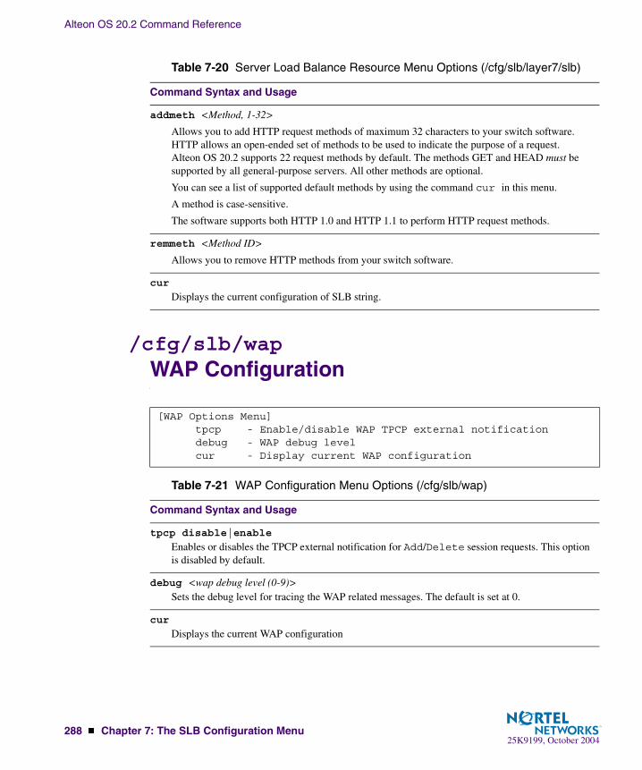
Alteon OS 20.2 Command Reference
288 � Chapter 7: The SLB Configuration Menu25K9199, October 2004
/cfg/slb/wapWAP Configuration
addmeth <Method, 1-32>
Allows you to add HTTP request methods of maximum 32 characters to your switch software. HTTP allows an open-ended set of methods to be used to indicate the purpose of a request. Alteon OS 20.2 supports 22 request methods by default. The methods GET and HEAD must be supported by all general-purpose servers. All other methods are optional.
You can see a list of supported default methods by using the command cur in this menu.
A method is case-sensitive.
The software supports both HTTP 1.0 and HTTP 1.1 to perform HTTP request methods.
remmeth <Method ID>
Allows you to remove HTTP methods from your switch software.
cur
Displays the current configuration of SLB string.
[WAP Options Menu] tpcp - Enable/disable WAP TPCP external notification debug - WAP debug level cur - Display current WAP configuration
Table 7-21 WAP Configuration Menu Options (/cfg/slb/wap)
Command Syntax and Usage
tpcp disable|enable
Enables or disables the TPCP external notification for Add/Delete session requests. This option is disabled by default.
debug <wap debug level (0-9)>Sets the debug level for tracing the WAP related messages. The default is set at 0.
cur
Displays the current WAP configuration
Table 7-20 Server Load Balance Resource Menu Options (/cfg/slb/layer7/slb)
Command Syntax and Usage

Alteon OS 20.2 Command Reference
Chapter 7: The SLB Configuration Menu � 28925K9199, October 2004
/cfg/slb/syncSynchronize Peer Switch Configuration
To synchronize the configuration between two switches, a peer must be configured and enabled on each switch. Switches being synchronized must use the same administrator pass-word. Peers are sent SLB, FILT, and VRRP configuration updates using /oper/slb/synch.
[Config Synchronization Menu] peer - Synch peer switch menu filt - Enable or disable syncing filter configuration ports - Enable or disable syncing port configuration prios - Enable or disable syncing VRRP priorities pips - Enable or disable syncing proxy IP addresses reals - Enable/disable syncing real server configuration state - Enable or disable syncing persistent session state update - Set stateful failover update period cur - Display current Layer 4 sync configuration
Table 7-22 Synchronization Menu Options (/cfg/slb/sync)
Command Syntax and Usage
peer <peer switch number (1-2)>Displays the Sync Peer Switch Menu. This option is enabled by default. To view menu options, see page 290.
filt disable|enable
Enables or disables synchronizing filter configuration.
ports disable|enable
Enables or disables synchronizing Layer 4 port configuration. This option is enabled by default.
prios disable|enable
Enables or disables syncing VRRP priorities. This option is enabled by default.
pips disable|enable
Enables or disables synchronizing proxy IP addresses. This option is disabled by default.
reals
Enables or disables synchronizing real server configuration. This option is disabled by default.
state disable|enable
Enables or disables stateful failover for synchronizing the persistent session state. This option is disabled by default.

Alteon OS 20.2 Command Reference
290 � Chapter 7: The SLB Configuration Menu25K9199, October 2004
/cfg/slb/sync/peer <peer switch number>Peer Switch Configuration
To synchronize the configuration between two switches, a peer must be configured and enabled on each switch. Switches being synchronized must use the same administrator pass-word.
update <seconds, 1–60>Sets the stateful failover update interval. The active server sends update packets of persistent bind-ing entries to the backup switch at the specified update interval. The default value is 30 seconds.
cur
Displays the current Layer 4 synchronization configuration.
[Peer Switch 1 Menu] addr - Set peer switch IP address ena - Enable peer switch dis - Disable peer switch del - Delete peer switch cur - Display current peer switch configuration
Table 7-23 Peer Switch Configuration Menu Options (/cfg/slb/sync/peer)
Command Syntax and Usage
addr <IP address>Sets the peer switch IP address. The default is 0.0.0.0
ena
Enables the peer for this switch. By default, this option is disabled.
dis
Disables the peer for this switch.
del
Deletes the peer for this switch
cur
Displays the current peer switch configuration.
Table 7-22 Synchronization Menu Options (/cfg/slb/sync)
Command Syntax and Usage

Alteon OS 20.2 Command Reference
Chapter 7: The SLB Configuration Menu � 29125K9199, October 2004
/cfg/slb/advAdvanced Layer 4 Configuration
[Layer 4 Advanced Menu] synatk - SYN Attack Detection Menu imask - Set virtual and real IP address mask mnet - Set managment network mmask - Set management subnet mask pmask - Set persistent mask timewin - Set time window for TCP rate limiting holddur - Set hold down duration for TCP rate limiting submac - Enable/Disable Source MAC address substitution direct - Enable/disable Direct Access Mode grace - Enable/disable graceful real server failure matrix - Enable/disable Virtual Matrix Architecture tpcp - Enable/disable Transparent Proxy Cache Protocol fastage - Session table fast-age (1 sec) period bit shift slowage - Session table slow-age (2 min) period bit shift cur - Display current Layer 4 advanced configuration
Table 7-24 Layer 4 Advanced Menu Options (/cfg/slb/adv)
Command Syntax and Usage
synatk
Displays SYN Attack Detection Menu. To view menu options, see page 293.
imask <IP subnet mask (such as 255.255.255.0)>Configures the real and virtual server IP address mask using dotted decimal notation. The default is 255.255.255.255.
mnet <IP address>If defined, management traffic with this source IP address will be allowed direct (non-Layer 4) access to the real servers. Specify an IP address in dotted decimal notation. A range of IP addresses is produced when used with the mmask option.
mmask <IP subnet mask (such as 255.255.255.0)>This IP address mask is used with the mnet to select management traffic which is allowed direct access to real servers. The default is 255.255.255.255.
pmask <IP subnet mask (such as 255.255.255.0)>Sets persistent mask. The default is 255.255.255.255.

Alteon OS 20.2 Command Reference
292 � Chapter 7: The SLB Configuration Menu25K9199, October 2004
timewin <multiple of fastage period (1-65535)>Sets the parameter for time window for TCP rate limiting, which is a multiple of the fastage period. For example, if the fastage parameter is 2 seconds, and the timewin is 3, then the resulting time window is 6 seconds.
holddur <multiple of slowage period (1-65535)>This command configures the hold down duration, which is a multiple of slowage. Hold down (blocking of new TCP connections) occurs when the number of received SYN packets exceeds the threshold of a pre-defined time window. For example, the parameter of slowage is 2 minutes, and holddur is 5, then the resulting hold down duration is 10 minutes.
submac disable|enable
Enables or disables Source MAC address substitution. Typically, the source MAC is not modified for the packets going to the servers in an SLB environment. But if you enable this command, the switch will substitute the source MAC address (for the packets going to the server) with the mac address of the switch.
direct disable|enable
Enable/disables Direct Access Mode to real servers/services. This option also allows any virtual server to load balance any real server. By default, this option is disabled.
grace disable|enable
Enables or disables graceful real server failure. Allows existing connections to newly failed server to gracefully continue. By default, this option is disabled.
matrix disable|enable
Enables or disables the use of Virtual Matrix Architecture on the GbE Switch Module. By default, this option is enabled.
tpcp disable|enable
Enables or disables the TPCP (Transparent Proxy Cache Protocol). This command is used for security reasons—the UDP port can be closed. By default, this option is disabled.
fastage <shift the fast-age (1sec) period 0-7 bits>Controls how frequently a fastage scan is performed. The default interval is two seconds. Each incremental increase of the value doubles the length of the interval.
The fastage scan is used to remove TCP sessions that have been closed with a FIN and sessions that have been identified by the slowage scan as idle for the maximum allowed period. If a large value of fastage is used, a session can remain in the session table for a few minutes. The default is 0.
Table 7-24 Layer 4 Advanced Menu Options (/cfg/slb/adv)
Command Syntax and Usage

Alteon OS 20.2 Command Reference
Chapter 7: The SLB Configuration Menu � 29325K9199, October 2004
/cfg/slb/adv/synatkSYN Attack Detection Configuration
slowage <shift the slow-age (2min) period 0-15 bits>Controls how frequently a slowage scan is performed. The default interval is two minutes. Each incremental increase of the value doubles the length of the interval. (Value is set in bits rather than seconds, which causes the time to double per increment).
The slowage scan is used to remove idle or non-TCP sessions from the session at the specified intervals. If a large value of slowage is used, a session can remain in the session table for months. The default is 0.
cur
Displays the current Layer 4 advanced configuration.
[SYN Attack Detection Menu] intrval - Set SYN attack detection interval thrshld - Set SYN attack alarm threshold cur - Display current SYN attack detection configuration
Table 7-25 SYN Attack Detection Menu Options (/cfg/slb/adv/synatk)
Command Syntax and Usage
intrval <SYN attack check interval in seconds (2-3600)>Sets the interval of SYN attack inspection.
thrshld <SYN attack alarm threshold (new half-open sessions/second) (1-100000)>Sets the threshold of SYN attack alarm.
cur Displays the current SYN attack detection configuration.
Table 7-24 Layer 4 Advanced Menu Options (/cfg/slb/adv)
Command Syntax and Usage

Alteon OS 20.2 Command Reference
294 � Chapter 7: The SLB Configuration Menu25K9199, October 2004
/cfg/slb/advhcAdvanced Layer 4 Health Check
[Layer 4 Advanced Health Check Menu] script - Scriptable Health Check Menu waphc - WAP Health Check Menu aphttp - Enable/disable Allow HTTP Health Check on any port ldapver - LDAP version secret - Set RADIUS secret minter - Set interval of response and bandwidth metric updates cur - Display current Layer 4 advanced health check configuration
Table 7-26 Advanced Health Check Menu Options (/cfg/slb/advhc)
Command Syntax and Usage
script <health script number (1-8)>Displays the Scriptable Health Check Menu. To view menu options, see page 295.
waphc
Displays the WAP Health Check Menu. To view menu options, see page 296.
aphttp disable|enable
Enables or disables HTTP health checks on any port. By default, this option is disabled. When dis-abled, you can use HTTP health checks only for HTTP service. Enabling it will allow you to use it on any port, like HTTPs.
ldapver <LDAP version>Sets the LDAP version to 2 or 3. The default is 2.
secret <1-32 character secret>To perform application health checking to a RADIUS server, the network administrator must con-figure two parameters in the switch: the /cfg/slb/advhc/secret value and the cntnt parameter with a username:password value. The secret value is a field of up to 32 alphanumeric characters that is used by the switch to encrypt a password during the RSA Message Digest Algo-rithm (MD5) and by the RADIUS server to decrypt the password during verification. The default is none.
minter <number of seconds between updates (1-256)>This command sets the interval of response and bandwidth metric updates. The default is set at 10.
cur Displays the current Layer 4 advanced health check configuration.

Alteon OS 20.2 Command Reference
Chapter 7: The SLB Configuration Menu � 29525K9199, October 2004
/cfg/slb/advhc/script <health script number>
Scriptable Health Checks Configuration
The Health Script menu provides commands that can be used to define the health “script.” The total number of characters cannot exceed 1024 bytes. Up to eight scripts can be configured.
[Health Script 1 Menu] open - Add open command to end of script send - Add send command to end of script expect - Add expect command to end of script close - Add close command to end of script rem - Remove last command from script del - Delete script cur - Display current script configuration
Table 7-27 Scriptable Health Check Menu Options (/cfg/slb/advhc/script)
Command Syntax and Usage
open <real port or name (such as: http)> Sets the TCP port to be opened.
send <text string>Sends an ASCII string through open TCP port. For example, an HTTP request, such as, "GET /default.asp HTTP/1.1\\r\\nHOST: www.alteon.com\\r\\n\\r\\n."
expect <text string>Expects an ASCII string for successful health check on open TCP port, such as an HTTP response: HTTP/1.1 200
close
Closes TCP connection.
rem
Removes the last entered line from the script.
del
Deletes the current script.
cur
Lists the current script configuration.

Alteon OS 20.2 Command Reference
296 � Chapter 7: The SLB Configuration Menu25K9199, October 2004
/cfg/slb/advhc/waphcWAP Health Check Configuration
[WAP Health Check Menu] wspport - WSP port number to health check wtlsprt - WTLS port number to health check offset - Offset in received WSP packet sndcnt - Content to be sent to the WAP gateway rcvcnt - Content to be received from the WAP gateway cur - Display current WAP health check configuration
Table 7-28 WAP Health Check Menu Options (/cfg/slb/advhc/waphc)
Command Syntax and Usage
wspport <port number (0-65534)>Enter the port number on which WSP health checks will be performed. The default port number is 9200.
wtlsprt <port number (0-65534)>Enter the port number on which WTLS health checks will be performed. The default port number is 9203.
offset <Offset in the received WSP packet (0-256)>Enter the offset value content of the received WSP packages. An offset value of 0 (default) sets the switch to start comparisons from the beginning of the content of the received packet.
sndcnt <send content as a hexadecimal string>Enter a hexidecimal string that represents a connectionless WSP request to a WSP gateway. This string will be delivered to the WSP gateway.
rcvcnt <receive content as a hexadecimal string>Enter a hexadecimal string that represents the content that the switch expects to receive from the WSP gateway.
cur Displays the current WAP Health Check configuration.
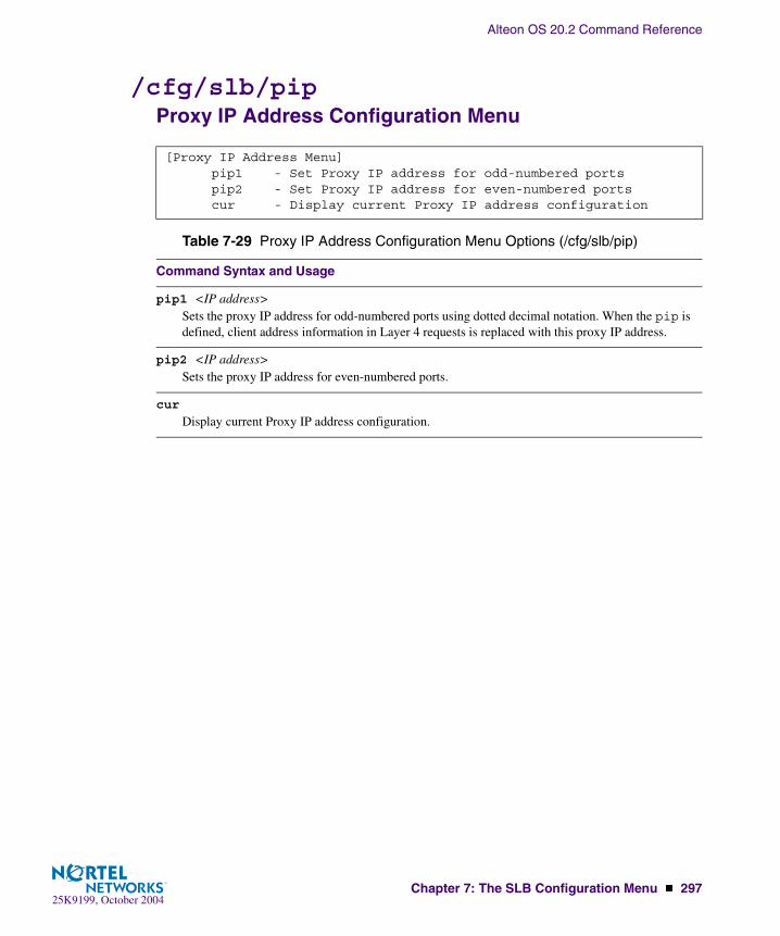
Alteon OS 20.2 Command Reference
Chapter 7: The SLB Configuration Menu � 29725K9199, October 2004
/cfg/slb/pip Proxy IP Address Configuration Menu
[Proxy IP Address Menu] pip1 - Set Proxy IP address for odd-numbered ports pip2 - Set Proxy IP address for even-numbered ports cur - Display current Proxy IP address configuration
Table 7-29 Proxy IP Address Configuration Menu Options (/cfg/slb/pip)
Command Syntax and Usage
pip1 <IP address>Sets the proxy IP address for odd-numbered ports using dotted decimal notation. When the pip is defined, client address information in Layer 4 requests is replaced with this proxy IP address.
pip2 <IP address>Sets the proxy IP address for even-numbered ports.
cur
Display current Proxy IP address configuration.

Alteon OS 20.2 Command Reference
298 � Chapter 7: The SLB Configuration Menu25K9199, October 2004
/cfg/slb/peerpip SLB Peer Proxy IP Address Configuration Menu
When this command is enabled, the switch is able to forward traffic from the other switch, using Layer 2, without performing server processing on the packets of the other switch. This happens because the peer switches are aware of each otherís proxy IP addresses. This prevents the dropping of a packet or being sent to the backup switch in the absence of the proxy IP address of
the peer switch.
[Peer Proxy IP Address Menu] add - Add peer Proxy IP address rem - Rem peer Proxy IP address cur - Display current peer Proxy IP address configuration
Table 7-30 Proxy IP Address Configuration Menu Options (/cfg/slb/peerpip)
Command Syntax and Usage
add <IP address>
Allows you to add a proxy IP address to the server load balancing peer.
remove <IP address>
Allows you to remove a proxy IP address from the server load balancing peer.
cur
Displays the current proxy address configuration of the peer.
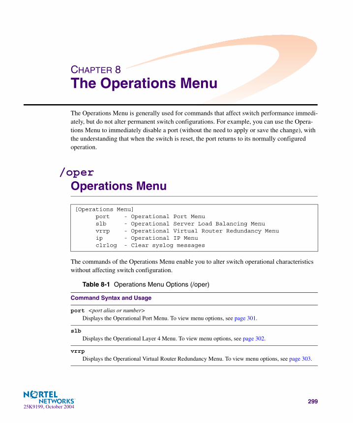
25K9199, October 2004299
CHAPTER 8The Operations Menu
The Operations Menu is generally used for commands that affect switch performance immedi-ately, but do not alter permanent switch configurations. For example, you can use the Opera-tions Menu to immediately disable a port (without the need to apply or save the change), with the understanding that when the switch is reset, the port returns to its normally configured operation.
/operOperations Menu
The commands of the Operations Menu enable you to alter switch operational characteristics without affecting switch configuration.
[Operations Menu] port - Operational Port Menu slb - Operational Server Load Balancing Menu vrrp - Operational Virtual Router Redundancy Menu ip - Operational IP Menu clrlog - Clear syslog messages
Table 8-1 Operations Menu Options (/oper)
Command Syntax and Usage
port <port alias or number>Displays the Operational Port Menu. To view menu options, see page 301.
slb
Displays the Operational Layer 4 Menu. To view menu options, see page 302.
vrrp
Displays the Operational Virtual Router Redundancy Menu. To view menu options, see page 303.

Alteon OS 20.2 Command Reference
300 � Chapter 8: The Operations Menu25K9199, October 2004
ip
Displays the IP Operations Menu, which has one sub-menu/option, the Operational Border Gate-way Protocol Menu. To view menu options, see page 303.
clrlog
Clears all Syslog messages.
Table 8-1 Operations Menu Options (/oper)
Command Syntax and Usage

Alteon OS 20.2 Command Reference
Chapter 8: The Operations Menu � 30125K9199, October 2004
/oper/port <port alias or number>Operations-Level Port Options
Operations-level port options are used for temporarily disabling or enabling a port, and for changing Remote Monitoring (RMON) status on a port.
[Operations Port INT1 Menu] rmon - Enable/Disable RMON for port ena - Enable port dis - Disable port cur - Current port state
Table 8-2 Operations-Level Port Menu Options (/oper/port)
Command Syntax and Usage
rmon disable|enable
Temporarily enables/disables Remote Monitoring on the port. The port will be returned to its con-figured operation mode when the switch is reset.
ena
Temporarily enables the port. The port will be returned to its configured operation mode when the switch is reset.
dis
Temporarily disables the port. The port will be returned to its configured operation mode when the switch is reset.
cur
Displays the current settings for the port.

Alteon OS 20.2 Command Reference
302 � Chapter 8: The Operations Menu25K9199, October 2004
/oper/slbOperations-Level SLB Options
When the optional Layer 4 software is enabled, the operations-level Server Load Balancing options are used for temporarily disabling or enabling real servers and synchronizing the con-figuration between the active/active switches.
[Server Load Balancing Operations Menu] sync - Synchronize SLB, VRRP and other configurations on peers ena - Enable real server dis - Disable real server clear - Clear session table cur - Current layer 4 operational state
Table 8-3 Server Load Balancing Operations Menu Options (/oper/slb)
Command Syntax and Usage
sync
Synchronizes the SLB, filter, VRRP, port, and VR priorities on a peer switch (a switch that owns the IP address). To take effect, peers must be configured on the GbE Switch Module and the administrator password on the switch must be identical.
ena <real server number (1-63)>Temporarily enables a real server. The real server will be returned to its configured operation mode when the switch is reset.
dis <real server number (1-63)> p|nThe disable command is used to temporarily disable real servers as follows:
� Using the n (none) option, disables the real server entirely, removing it from operation within its real server group and virtual server
� Using the p (persistent) option, temporarily disables sessions except for persistent http 1.0 ses-sions.
The real server will be returned to its configured operation mode when the switch is reset.
clear
Clears all session tables and allows port filter changes to take effect immediately.
Note: This command disrupts current Server Load Balancing and Application Redirection sessions.
cur
Displays the current SLB operational state.

Alteon OS 20.2 Command Reference
Chapter 8: The Operations Menu � 30325K9199, October 2004
/oper/vrrpOperations-Level VRRP Options.
/oper/ipOperations-Level IP Options
[VRRP Operations Menu] back - Set virtual router to backup
Table 8-4 Virtual Router Redundancy Operations Menu Options (/oper/vrrp)
Command Syntax and Usage
back <virtual router number (1-128)>Forces the specified master virtual router on this switch into backup mode. This is generally used for passing master control back to a preferred switch once the preferred switch has been returned to service after a failure. When this command is executed, the current master gives up control and ini-tiates a new election by temporarily advertising its own priority level as 0 (lowest). After the new election, the virtual router forced into backup mode by this command will resume master control in the following cases:
� This switch owns the virtual router (the IP addresses of the virtual router and its IP interface are the same)
� This switch’s virtual router has a higher priority and preemption is enabled.� There are no other virtual routers available to take master control.
[IP Operations Menu] bgp - Operational Border Gateway Protocol Menu
Table 8-5 IP Operations Menu Options (/oper/ip)
Command Syntax and Usage
bgp
Displays the Border Gateway Protocol Operations Menu. To view the menu options see page 304.

Alteon OS 20.2 Command Reference
304 � Chapter 8: The Operations Menu25K9199, October 2004
/oper/ip/bgpOperations-Level BGP Options
[Border Gateway Protocol Operations Menu] start - Start peer session stop - Stop peer session current - Current BGP operational state
Table 8-6 IP Operations Menu Options (/oper/ip)
Command Syntax and Usage
start <peer number (1-16)>Starts the peer session.
stop <peer number (1-16)>Stops the peer session.
cur
Displays the current BGP operational state.
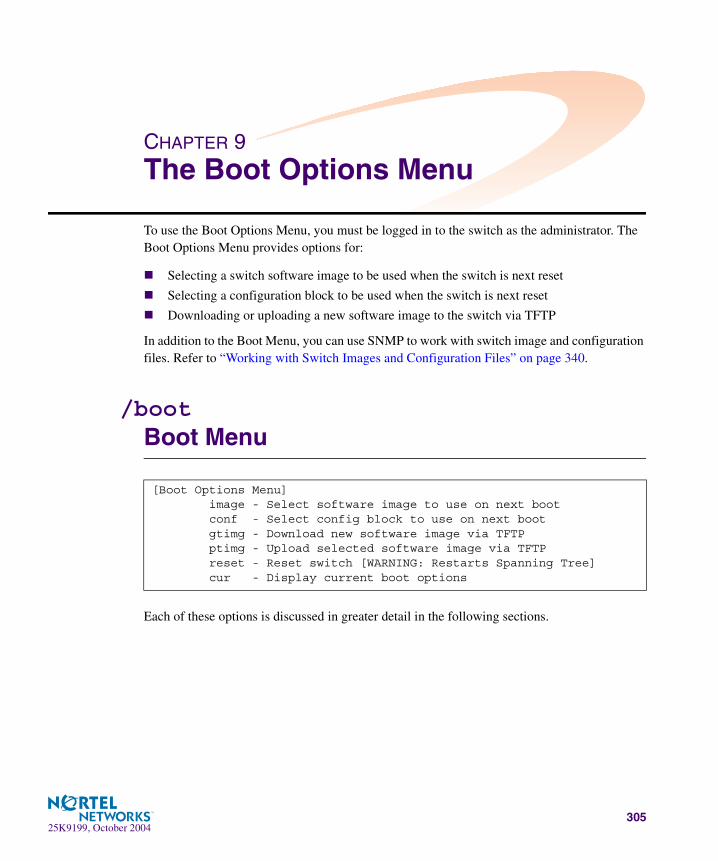
25K9199, October 2004305
CHAPTER 9The Boot Options Menu
To use the Boot Options Menu, you must be logged in to the switch as the administrator. The Boot Options Menu provides options for:
� Selecting a switch software image to be used when the switch is next reset
� Selecting a configuration block to be used when the switch is next reset
� Downloading or uploading a new software image to the switch via TFTP
In addition to the Boot Menu, you can use SNMP to work with switch image and configuration files. Refer to “Working with Switch Images and Configuration Files” on page 340.
/bootBoot Menu
Each of these options is discussed in greater detail in the following sections.
[Boot Options Menu] image - Select software image to use on next boot conf - Select config block to use on next boot gtimg - Download new software image via TFTP ptimg - Upload selected software image via TFTP reset - Reset switch [WARNING: Restarts Spanning Tree] cur - Display current boot options

Alteon OS 20.2 Command Reference
306 � Chapter 9: The Boot Options Menu25K9199, October 2004
Updating the Switch Software Image
The switch software image is the executable code running on the GbE Switch Module. A version of the image ships with the switch, and comes pre-installed on the device. As new versions of the image are released, you can upgrade the software running on your switch. To get the latest version of software available for your GbE Switch Module, go to:
http://www.ibm.com/pc/support
Click on software updates. Use /boot/cur to determine the current software version.
Upgrading the software image on your switch requires the following:
� Loading the new image onto a TFTP server on your network
� Downloading the new image from the TFTP server to your switch
� Selecting the new software image to be loaded into switch memory the next time the switch is reset
Downloading New Software to Your SwitchThe switch can store up to two different software images, called image1 and image2, as well as boot software, called boot. When you download new software, you must specify where it should be placed: either into image1, image2, or boot.
For example, if your active image is currently loaded into image1, you would probably load the new image software into image2. This lets you test the new software and reload the origi-nal active image (stored in image1), if needed.
To download a new software to your switch, you will need the following:
� The image or boot software loaded on a TFTP server on your network
� The hostname or IP address of the TFTP server
� The name of the new software image or boot file
NOTE – The DNS parameters must be configured if specifying hostnames. See “Domain Name System Configuration” on page 234.
When the above requirements are met, use the following procedure to download the new soft-ware to your switch.
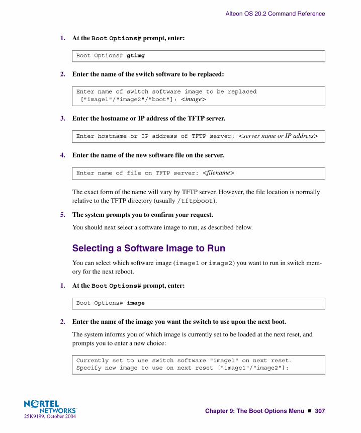
Alteon OS 20.2 Command Reference
Chapter 9: The Boot Options Menu � 30725K9199, October 2004
1. At the Boot Options# prompt, enter:
2. Enter the name of the switch software to be replaced:
3. Enter the hostname or IP address of the TFTP server.
4. Enter the name of the new software file on the server.
The exact form of the name will vary by TFTP server. However, the file location is normally relative to the TFTP directory (usually /tftpboot).
5. The system prompts you to confirm your request.
You should next select a software image to run, as described below.
Selecting a Software Image to RunYou can select which software image (image1 or image2) you want to run in switch mem-ory for the next reboot.
1. At the Boot Options# prompt, enter:
2. Enter the name of the image you want the switch to use upon the next boot.
The system informs you of which image is currently set to be loaded at the next reset, and prompts you to enter a new choice:
Boot Options# gtimg
Enter name of switch software image to be replaced["image1"/"image2"/"boot"]: <image>
Enter hostname or IP address of TFTP server: <server name or IP address>
Enter name of file on TFTP server: <filename>
Boot Options# image
Currently set to use switch software "image1" on next reset.Specify new image to use on next reset ["image1"/"image2"]:

Alteon OS 20.2 Command Reference
308 � Chapter 9: The Boot Options Menu25K9199, October 2004
Uploading a Software Image from Your SwitchYou can upload a software image from the switch to a TFTP server.
1. At the Boot Options# prompt, enter:
2. The system prompts you for information. Enter the desired image:
3. Enter the name or the IP address of the TFTP server:
4. Enter the name of the file into which the image will be uploaded on the TFTP server:
5. The system then requests confirmation of what you have entered. To have the file uploaded, enter Y.
Boot Options# ptimg
Enter name of switch software image to be uploaded["image1"|"image2"|"boot"]: <image> <hostname or server-IP-addr> <server-file-name>
Enter hostname or IP address of TFTP server: <server name or IP address>
Enter name of file on TFTP server: <filename>
image2 currently contains Software Version 20.0.1.0Upload will transfer image2 (1889411 bytes) to file "test" on TFTP server 192.1.1.1.Confirm upload operation [y/n]: y

Alteon OS 20.2 Command Reference
Chapter 9: The Boot Options Menu � 30925K9199, October 2004
Selecting a Configuration Block
When you make configuration changes to the GbE Switch Module, you must save the changes so that they are retained beyond the next time the switch is reset. When you perform the save command, your new configuration changes are placed in the active configuration block. The previous configuration is copied into the backup configuration block.
There is also a factory configuration block. This holds the default configuration set by the factory when your GbE Switch Module was manufactured. Under certain circumstances, it may be desir-able to reset the switch configuration to the default. This can be useful when a custom-configured GbE Switch Module is moved to a network environment where it will be re configured for a differ-ent purpose.
Use the following procedure to set which configuration block you want the switch to load the next time it is reset:
1. At the Boot Options# prompt, enter:
2. Enter the name of the configuration block you want the switch to use:
The system informs you of which configuration block is currently set to be loaded at the next reset, and prompts you to enter a new choice:
Boot Options# conf
Currently set to use active configuration block on next reset.Specify new block to use ["active"/"backup"/"factory"]:
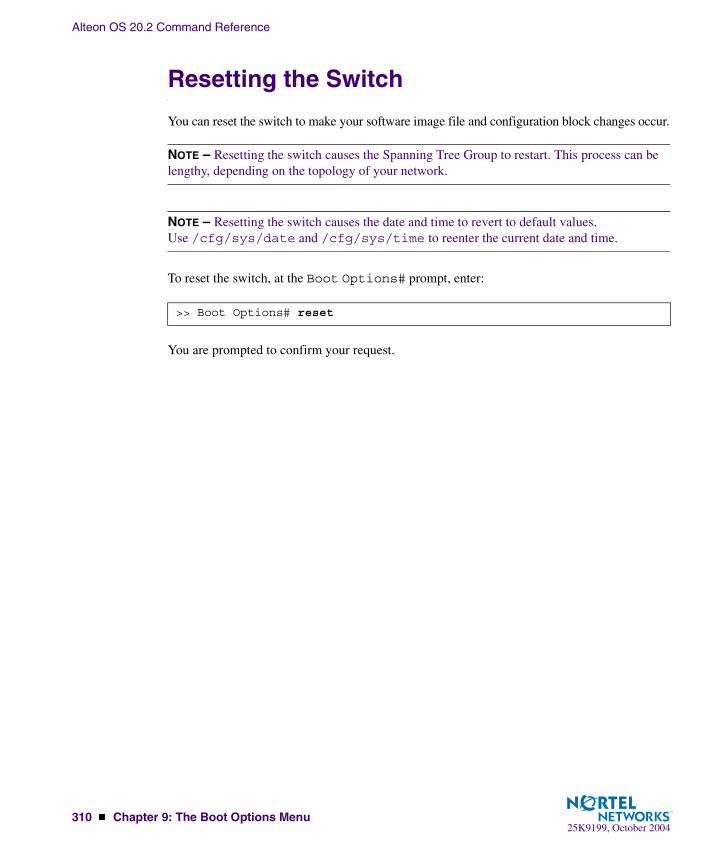
Alteon OS 20.2 Command Reference
310 � Chapter 9: The Boot Options Menu25K9199, October 2004
Resetting the Switch
You can reset the switch to make your software image file and configuration block changes occur.
NOTE – Resetting the switch causes the Spanning Tree Group to restart. This process can be lengthy, depending on the topology of your network.
NOTE – Resetting the switch causes the date and time to revert to default values. Use /cfg/sys/date and /cfg/sys/time to reenter the current date and time.
To reset the switch, at the Boot Options# prompt, enter:
You are prompted to confirm your request.
>> Boot Options# reset
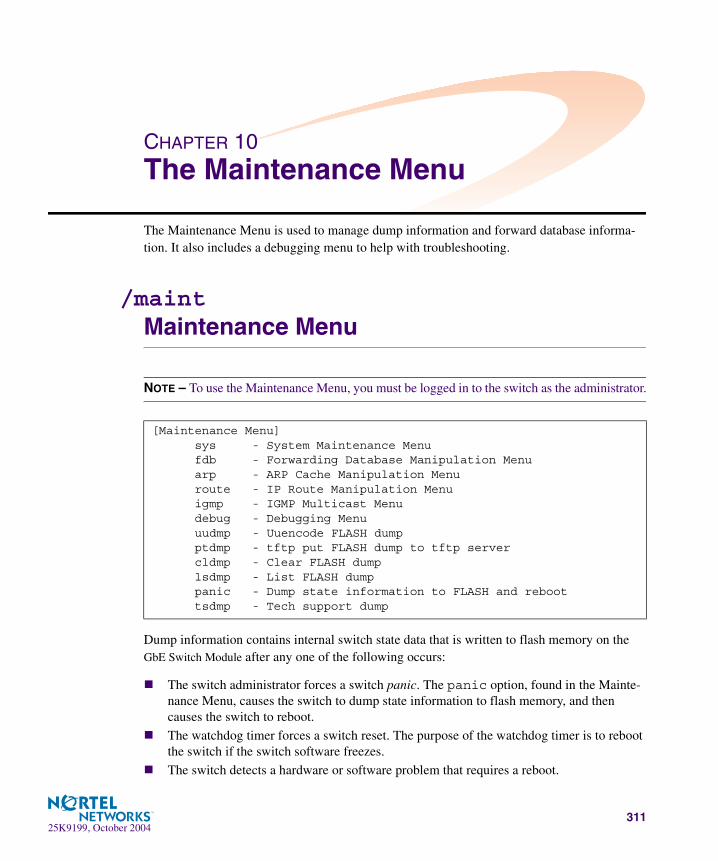
25K9199, October 2004311
CHAPTER 10The Maintenance Menu
The Maintenance Menu is used to manage dump information and forward database informa-tion. It also includes a debugging menu to help with troubleshooting.
/maintMaintenance Menu
NOTE – To use the Maintenance Menu, you must be logged in to the switch as the administrator.
Dump information contains internal switch state data that is written to flash memory on the GbE Switch Module after any one of the following occurs:
� The switch administrator forces a switch panic. The panic option, found in the Mainte-nance Menu, causes the switch to dump state information to flash memory, and then causes the switch to reboot.
� The watchdog timer forces a switch reset. The purpose of the watchdog timer is to reboot the switch if the switch software freezes.
� The switch detects a hardware or software problem that requires a reboot.
[Maintenance Menu] sys - System Maintenance Menu fdb - Forwarding Database Manipulation Menu arp - ARP Cache Manipulation Menu route - IP Route Manipulation Menu igmp - IGMP Multicast Menu debug - Debugging Menu uudmp - Uuencode FLASH dump ptdmp - tftp put FLASH dump to tftp server cldmp - Clear FLASH dump lsdmp - List FLASH dump panic - Dump state information to FLASH and reboot tsdmp - Tech support dump
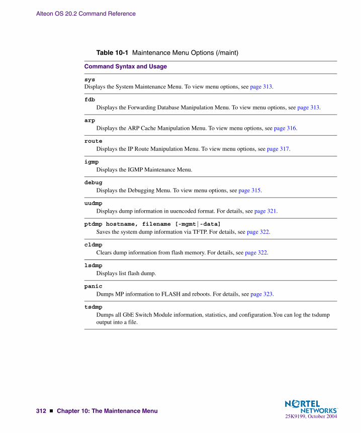
Alteon OS 20.2 Command Reference
312 � Chapter 10: The Maintenance Menu25K9199, October 2004
Table 10-1 Maintenance Menu Options (/maint)
Command Syntax and Usage
sysDisplays the System Maintenance Menu. To view menu options, see page 313.
fdb
Displays the Forwarding Database Manipulation Menu. To view menu options, see page 313.
arp
Displays the ARP Cache Manipulation Menu. To view menu options, see page 316.
route
Displays the IP Route Manipulation Menu. To view menu options, see page 317.
igmp
Displays the IGMP Maintenance Menu.
debug
Displays the Debugging Menu. To view menu options, see page 315.
uudmp
Displays dump information in uuencoded format. For details, see page 321.
ptdmp hostname, filename [-mgmt|-data]
Saves the system dump information via TFTP. For details, see page 322.
cldmp
Clears dump information from flash memory. For details, see page 322.
lsdmp
Displays list flash dump.
panic
Dumps MP information to FLASH and reboots. For details, see page 323.
tsdmp
Dumps all GbE Switch Module information, statistics, and configuration.You can log the tsdump output into a file.
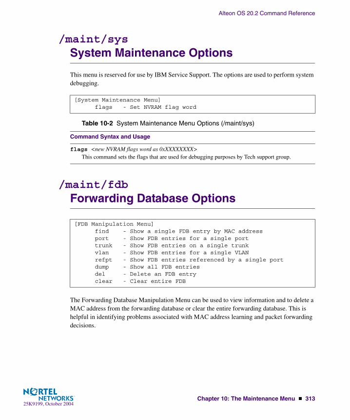
Alteon OS 20.2 Command Reference
Chapter 10: The Maintenance Menu � 31325K9199, October 2004
/maint/sysSystem Maintenance Options
This menu is reserved for use by IBM Service Support. The options are used to perform system debugging.
/maint/fdbForwarding Database Options
The Forwarding Database Manipulation Menu can be used to view information and to delete a MAC address from the forwarding database or clear the entire forwarding database. This is helpful in identifying problems associated with MAC address learning and packet forwarding decisions.
[System Maintenance Menu] flags - Set NVRAM flag word
Table 10-2 System Maintenance Menu Options (/maint/sys)
Command Syntax and Usage
flags <new NVRAM flags word as 0xXXXXXXXX>This command sets the flags that are used for debugging purposes by Tech support group.
[FDB Manipulation Menu] find - Show a single FDB entry by MAC address port - Show FDB entries for a single port trunk - Show FDB entries on a single trunk vlan - Show FDB entries for a single VLAN refpt - Show FDB entries referenced by a single port dump - Show all FDB entries del - Delete an FDB entry clear - Clear entire FDB
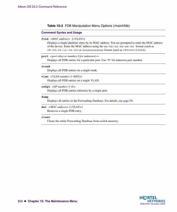
Alteon OS 20.2 Command Reference
314 � Chapter 10: The Maintenance Menu25K9199, October 2004
Table 10-3 FDB Manipulation Menu Options (/maint/fdb)
Command Syntax and Usage
find <MAC address> [<VLAN>]Displays a single database entry by its MAC address. You are prompted to enter the MAC address of the device. Enter the MAC address using the xx:xx:xx:xx:xx:xx format (such as 08:00:20:12:34:56) or xxxxxxxxxxxx format (such as 080020123456).
port <port alias or number, 0 for unknown>>Displays all FDB entries for a particular port. Use “0” for unknown port number.
trunk
Displays all FDB entries on a single trunk.
vlan <VLAN number (1-4095)>Displays all FDB entries on a single VLAN.
refpt <SP number (1-4)>Displays all FDB entries reference by a single port.
dump
Displays all entries in the Forwarding Database. For details, see page 59.
del <MAC address> [<VLAN>]Removes a single FDB entry.
clear
Clears the entire Forwarding Database from switch memory.

Alteon OS 20.2 Command Reference
Chapter 10: The Maintenance Menu � 31525K9199, October 2004
/maint/debugDebugging Options
The Miscellaneous Debug Menu displays trace buffer information about events that can be helpful in understanding switch operation. You can view the following information using the debug menu:
� Events traced by the Management Processor (MP)
� Events traced by the Switch Processor (SP)
� Events traced to a buffer area when a reset occurs
If the switch resets for any reason, the MP trace buffer and SP trace buffers are saved into the snap trace buffer area. The output from these commands can be interpreted by IBM Service Support.
[Miscellaneous Debug Menu] tbuf - Show MP trace buffer sptb - Show SP trace buffer spall - Show All SP trace buffers clrcfg - Clear all flash configs vmasp - Show designated SP for IP address
Table 10-4 Miscellaneous Debug Menu Options (/maint/debug)
Command Syntax and Usage
tbuf
Displays the Management Processor trace buffer. Header information similar to the following is shown:
MP trace buffer at 13:28:15 Fri May 25, 2001; mask: 0x2ffdf748
The buffer information is displayed after the header.
snap
Displays the Management Processor snap (or post-mortem) trace buffer. This buffer contains infor-mation traced at the time that a reset occurred.
sptb <port number (1-4)>
Displays the Switch Processor trace buffer. Header information similar to the following is shown:
SP 1 trace buffer at 10:56:35 Tue Jul 30, 2002; mask: 0x00800008
The buffer information is displayed after the header.
spall
Displays the Switch Processor trace buffer. Header information similar to the following is shown:
SP 1 trace buffer at 10:56:35 Tue Jul 30, 2002; mask: 0x00800008.
The buffer information is displayed after the header. Displays all SP trace buffers.
clrcfg
Deletes all flash configuration blocks.

Alteon OS 20.2 Command Reference
316 � Chapter 10: The Maintenance Menu25K9199, October 2004
/maint/arpARP Cache Options
vmasp <IP address>
Displays the assigned SP (Switch Processor) for this IP address.
[Address Resolution Protocol Menu] find - Show a single ARP entry by IP address port - Show ARP entries on a single port vlan - Show ARP entries on a single VLAN refpt - Show ARP entries referenced by a single port dump - Show all ARP entries add - Add a permanent ARP entry del - Delete an ARP entry clear - Clear ARP cache addr - Show ARP address list
Table 10-4 Miscellaneous Debug Menu Options (/maint/debug)
Command Syntax and Usage

Alteon OS 20.2 Command Reference
Chapter 10: The Maintenance Menu � 31725K9199, October 2004
NOTE – To display all ARP entries currently held in the switch, or a portion according to one of the options listed on the menu above (find, port, vlan, refpt, dump), you can also refer to “ARP Information” on page 70.
/maint/routeIP Route Manipulation
Table 10-5 Address Resolution Protocol Menu Options (/maint/arp)
Command Syntax and Usage
find <IP address (such as, 192.4.17.101)>Shows a single ARP entry by IP address.
port <port alias or number>Shows ARP entries on a single port.
vlan <VLAN number>Shows ARP entries on a single VLAN.
refpt <SP number (1-4)>Shows all ARP entries referenced by a single port.
dump
Shows all ARP entries.
add <IP address> <MAC address> <VLAN number> <port>
Adds a single ARP entry from switch memory.
del <IP address (such as, 192.4.17.101)>Removes a single ARP entry from switch memory.
clear
Clears the entire ARP list from switch memory.
addr
Shows the list of IP addresses which the switch will respond to for ARP requests.
[IP Routing Menu] find - Show a single route by destination IP address gw - Show routes to a single gateway type - Show routes of a single type tag - Show routes of a single tag if - Show routes on a single interface dump - Show all routes clear - Clear route table
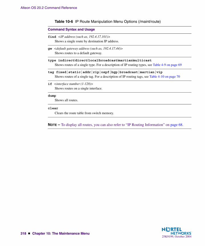
Alteon OS 20.2 Command Reference
318 � Chapter 10: The Maintenance Menu25K9199, October 2004
NOTE – To display all routes, you can also refer to “IP Routing Information” on page 68.
Table 10-6 IP Route Manipulation Menu Options (/maint/route)
Command Syntax and Usage
find <IP address (such as, 192.4.17.101)>Shows a single route by destination IP address.
gw <default gateway address (such as, 192.4.17.44)>Shows routes to a default gateway.
type indirect|direct|local|broadcast|martian|multicastShows routes of a single type. For a description of IP routing types, see Table 4-9 on page 69
tag fixed|static|addr|rip|ospf|bgp|broadcast|martian|vip
Shows routes of a single tag. For a description of IP routing tags, see Table 4-10 on page 70
if <interface number (1-128)>Shows routes on a single interface.
dump
Shows all routes.
clear
Clears the route table from switch memory.

Alteon OS 20.2 Command Reference
Chapter 10: The Maintenance Menu � 31925K9199, October 2004
/maint/igmpIGMP Configuration
Table 10-7 describes the IGMP Maintenance commands.
[IGMP Menu] snoop - IGMP Snooping Menu mrouter - IGMP Multicast Router Port Menu dump - Dump all IGMP items clear - Clear all IGMP tables
Table 10-7 IGMP Multicast Group Menu Options (/maint/igmp)
Command Syntax and Usage
snoop
Displays IGMP multicast group information.
mrouter
Displays static Multicast Router information.
dump
Displays all IGMP information.
clear
Clears all IGMP tables.

Alteon OS 20.2 Command Reference
320 � Chapter 10: The Maintenance Menu25K9199, October 2004
/maint/igmp/snoopIGMP Multicast Router Port Information
Table 10-8 describes the IGMP Snooping Maintenance commands.
[IGMP Snooping Menu] find - Show a single group by IP group address vlan - Show groups on a single vlan port - Show groups on a single port dump - Show all groups clear - Clear group table
Table 10-8 IGMP Multicast Group Menu Options (/maint/igmp/snoop)
Command Syntax and Usage
find <IP address>Displays a single IGMP multicast group by its IP address.
vlan <VLAN number>Displays all IGMP multicast groups on a single VLAN.
port <Port number or alias>Displays all IGMP multicast groups on a single port.
dump
Displays information for all multicast groups.
clear
Clears the IGMP group table.

Alteon OS 20.2 Command Reference
Chapter 10: The Maintenance Menu � 32125K9199, October 2004
/maint/igmp/mrouterIGMP Multicast Router Port Information
Table 10-9 describes the multicast router maintenacne commands.
/maint/uudmpUuencode Flash Dump
Using this command, dump information is presented in uuencoded format. This format makes it easy to capture the dump information as a file or a string of characters.
If you want to capture dump information to a file, set your communication software on your workstation to capture session data prior to issuing the uudmp command. This will ensure that you do not lose any information. Once entered, the uudmp command will cause approximately 23,300 lines of data to be displayed on your screen and copied into the file.
Using the uudmp command, dump information can be read multiple times. The command does not cause the information to be updated or cleared from flash memory.
[IGMP Multicast Router Ports Menu] vlan - Show all learned multicast router ports on a single vlan dump - Show all learned multicast router ports versions - Show last detected multicast router IGMP versions clear - Clear multicast router port table
Table 10-9 IGMP Multicast Router Menu Options (/maint/igmp/mrouter)
Command Syntax and Usage
vlan
Displays information for all multicast groups learned on the selected VLAN.
dump
Displays information for all multicast groups learned by the switch.
versions
Displays the IGMP version of the most recent multicast group learned by the switch.
clear
Clears the IGMP multicast router port table.

Alteon OS 20.2 Command Reference
322 � Chapter 10: The Maintenance Menu25K9199, October 2004
NOTE – Dump information is not cleared automatically. In order for any subsequent dump information to be written to flash memory, you must manually clear the dump region. For more information on clearing the dump region, see page 322.
To access dump information, at the Maintenance# prompt, enter:
The dump information is displayed on your screen and, if you have configured your communi-cation software to do so, captured to a file. If the dump region is empty, the following appears:
/maint/ptdmp <server> <filename>TFTP System Dump Put
Use this command to put (save) the system dump to a TFTP server.
NOTE – If the TFTP server is running SunOS or the Solaris operating system, the specified ptdmp file must exist prior to executing the ptdmp command, and must be writable (set with proper permission, and not locked by any application). The contents of the specified file will be replaced with the current dump data.
To save dump information via TFTP, at the Maintenance# prompt, enter:
Where server is the TFTP server IP address or hostname, and filename is the target dump file.
/maint/cldmpClearing Dump Information
To clear dump information from flash memory, at the Maintenance# prompt, enter:
The switch clears the dump region of flash memory and displays the following message:
Maintenance# uudmp
No FLASH dump available.
Maintenance# ptdmp <server> <filename>
Maintenance# cldmp
FLASH dump region cleared.
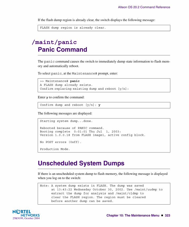
Alteon OS 20.2 Command Reference
Chapter 10: The Maintenance Menu � 32325K9199, October 2004
If the flash dump region is already clear, the switch displays the following message:
/maint/panicPanic Command
The panic command causes the switch to immediately dump state information to flash mem-ory and automatically reboot.
To select panic, at the Maintenance# prompt, enter:
Enter y to confirm the command:
The following messages are displayed:
Unscheduled System Dumps
If there is an unscheduled system dump to flash memory, the following message is displayed when you log on to the switch:
FLASH dump region is already clear.
>> Maintenance# panicA FLASH dump already exists.Confirm replacing existing dump and reboot [y/n]:
Confirm dump and reboot [y/n]: y
Starting system dump...done.
Rebooted because of PANIC command.Booting complete 0:01:01 Thu Jul 1, 2003:Version 1.0.0.18 from FLASH image1, active config block.
No POST errors (0xff).
Production Mode.
Note: A system dump exists in FLASH. The dump was savedat 13:43:22 Wednesday October 30, 2002. Use /maint/uudmp toextract the dump for analysis and /maint/cldmp toclear the FLASH region. The region must be clearedbefore another dump can be saved.

Alteon OS 20.2 Command Reference
324 � Chapter 10: The Maintenance Menu25K9199, October 2004

25K9199, October 2004325
APPENDIX AAlteon OS Syslog Messages
The following syntax is used when outputting syslog messages:
<Time stamp><Log Label>Web OS<Thread ID>:<Message>
where
� <Timestamp>
The time of the message event is displayed in month day hour:minute:second format. For example: Aug 19 14:20:30
� <Log Label>
The following types of log messages are recorded: LOG_EMERG, LOG_ALERT, LOG_CRIT, LOG_ERR, LOG_WARNING, LOG_NOTICE, LOG_INFO, and LOG_DEBUG
� <Thread ID>
This is the software thread that reports the log message. The following thread IDs are recorded: stg, ip, slb, console, telnet, vrrp, system, web server, ssh, and bgp
� <Message>: The log message
Following is a list of potential syslog messages. To keep this list as short as possible, only <Thread ID> and <Message> are shown. The messages are sorted by <Log Label>.
Where the <Thread ID> is listed as mgmt, one of the following may be shown: console, telnet, web server, or ssh.
LOG_WARNING
FILTER “filter <filter number> fired on port <port number>, <source IP address> -> <desti-nation IP address>, [<ICMP type>], [<IP protocol>], [<layer-4 ports>], [<TCP f1ags>]”

Alteon OS 20.2 Command Reference
326 � Appendix A: Alteon OS Syslog Messages25K9199, October 2004
LOG_ALERT
stp: own BPDU received from port <port_id>
IP cannot contact default gateway <ip_address>
vrrp: received errored advertisement from <ip_address>
vrrp: received incorrect password from <ip_address>
vrrp: received incorrect addresses from <ip_address>
vrrp: received incorrect advertisement interval <seconds> from <ip_address>
slb: cannot contact real server <ip_address>
slb: real server <ip_address> has reached maximum connections
slb: cannot contact real service <ip_address:real_port>
slb: real server failure threshold (<threshold>) has been reach for group <group_id>
slb: real server <ip_address> disabled through configuration
slb: Virtual Service Pool full. gSvcPool=MAX_SERVICES
bgp: notification (<reason>) received from <BGP peer ip_address>
bgp: session with <BGP peer ip_address> failed (<reason>)
vrrp: Synchronization from non-configured peer <ip_address>
vrrp: Synchronization from non-configured peer <ip_address> was blocked
dps: hold down triggered: <ip_address> for <min> minutes
dps: manual hold down: <ip_address>
syn_atk SYN attack detected: <count> new half-open sessions per second
tcplim hold down triggered: <ip_address> for <min> minutes
LOG_CRIT
SYSTEM: temperature at sensor <sensor_id> exceeded threshold
SYSTEM: internal power supply failed
SYSTEM: redundant power supply failed

Alteon OS 20.2 Command Reference
Appendix A: Alteon OS Syslog Messages � 32725K9199, October 2004
SYSTEM: fan failure detected
SSH can’t allocate memory in load_MP_INT
LOG_ERR
mgmt: PANIC at <file>:<line> in thread <thread id>
mgmt: VERIFY at <file>:<line> in thread <thread id>
mgmt: ASSERT at <file>:<line> in thread <thread id>
ntp: cannot contact NTP server <ip_address>
ntp: unable to listen to NTP port
isd: unable to listen to BOOTP_SERVER_PORT port
stp: Error: Error writing STG config to FLASH
stp: Error: Error writing config to FLASH
mgmt: Apply not done
mgmt: Save not done
mgmt: “ <““apply””|““save””> is issued by another user. Try later”
cli: Error: Error writing %s config to FLASH
cli: New Path Cost for Port <port_id> is invalid
cli: PVID <vlan_id> for port <port_id> is not created
cli: RADIUS secret must be 1-32 characters long
cli: Please configure primary RADIUS server address
cli: STP changes can't be applied since STP is OFF
cli: Switch reset is required to turn STP on/off
cli: Trunk group <trunk_id> contains ports with different PVIDs
cli: Trunk group <trunk_id> has more than <max_trunk_ports> ports
cli: Trunk group <trunk_id> contains no ports but is enabled
cli: Not all ports in trunk group <trunk_id> are in VLAN <vlan_id>
cli: Trunk groups <trunk_id> and <trunk_id> can not share the same port
LOG_CRIT (Continued)

Alteon OS 20.2 Command Reference
328 � Appendix A: Alteon OS Syslog Messages25K9199, October 2004
port_mirr: Port Mirroring changes are not applied
cli: Broadcast address for IP interface <interface_id> is invalid
cli: IP Interfaces <interface_id> and <interface_id> are on the same subnet
cli: Multiple static routes have same destination
cli: Virtual router <vr_id> must have sharing disabled when hotstandby is enabled
cli: Virtual router group must be enabled when hotstandby is enabled
cli: At least one virtual router must be enabled when group is enabled
cli: Virtual router group must have sharing disabled when hotstandby is enabled
cli: Virtual router group must have preemption enabled when hotstandby is enabled
cli: Virtual router <vr_id> must have an IP address
cli: Virtual router <vr_id> cannot have same VRID and VLAN as <vlan_id>
cli: Virtual router <vr_id> cannot have same IP address as <ip_address>
cli: Virtual router <vr_id> corresponding virtual server <server_id> is not enabled
cli: Hot-standby must be enabled when a virtual router has a PIP address
cli: Virtual router <vr_id> IP interface should be <interface_id>
cli: Enabled real server <server_id> has no IP address
cli: Real server <server_id> has same IP address as IP interface <interface_id>
cli: Real server <server_id> has same IP address as switch
cli: Real server <server_id> (Backup for <server_id>) is not enabled
cli: Real server <server_id> has same IP address as virtual server <server_id>
cli: Real server <server_id> has same IP address as real server <server_id>
cli: Real server group <group_id> cannot backup itself
cli: Real server <server_id> cannot be added to same group
cli: Enabled virtual server <server_id> has no IP address
cli: Virtual server <server_id> has same IP address as IP interface <interface_id>
cli: Virtual server <server_id> has same IP address as switch
LOG_ERR (Continued)
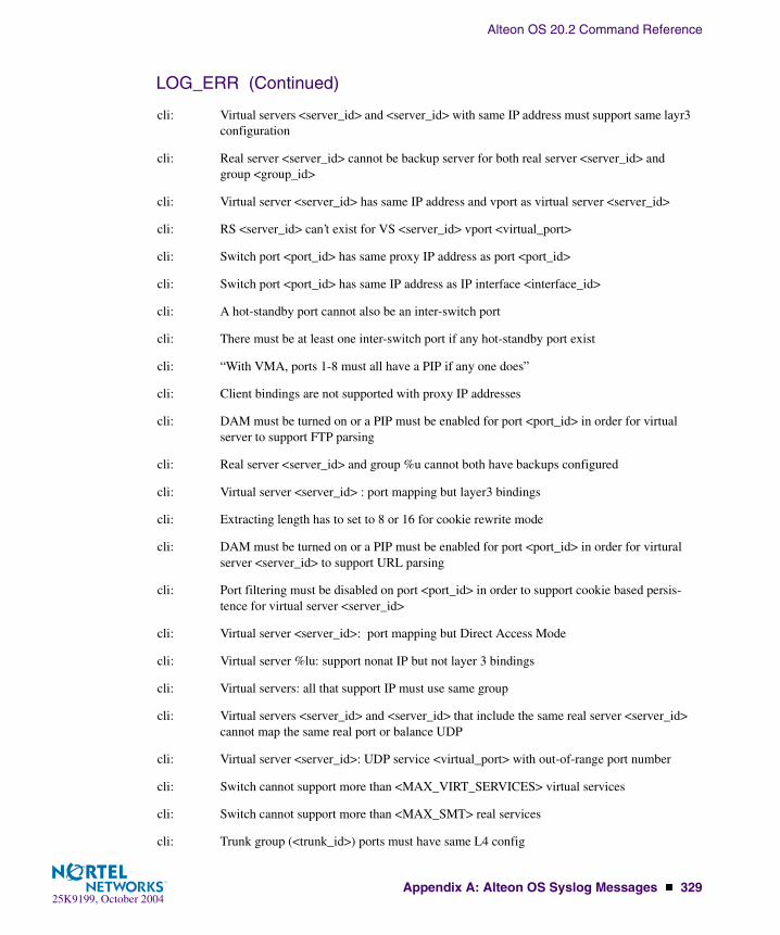
Alteon OS 20.2 Command Reference
Appendix A: Alteon OS Syslog Messages � 32925K9199, October 2004
cli: Virtual servers <server_id> and <server_id> with same IP address must support same layr3 configuration
cli: Real server <server_id> cannot be backup server for both real server <server_id> and group <group_id>
cli: Virtual server <server_id> has same IP address and vport as virtual server <server_id>
cli: RS <server_id> can’t exist for VS <server_id> vport <virtual_port>
cli: Switch port <port_id> has same proxy IP address as port <port_id>
cli: Switch port <port_id> has same IP address as IP interface <interface_id>
cli: A hot-standby port cannot also be an inter-switch port
cli: There must be at least one inter-switch port if any hot-standby port exist
cli: “With VMA, ports 1-8 must all have a PIP if any one does”
cli: Client bindings are not supported with proxy IP addresses
cli: DAM must be turned on or a PIP must be enabled for port <port_id> in order for virtual server to support FTP parsing
cli: Real server <server_id> and group %u cannot both have backups configured
cli: Virtual server <server_id> : port mapping but layer3 bindings
cli: Extracting length has to set to 8 or 16 for cookie rewrite mode
cli: DAM must be turned on or a PIP must be enabled for port <port_id> in order for virtural server <server_id> to support URL parsing
cli: Port filtering must be disabled on port <port_id> in order to support cookie based persis-tence for virtual server <server_id>
cli: Virtual server <server_id>: port mapping but Direct Access Mode
cli: Virtual server %lu: support nonat IP but not layer 3 bindings
cli: Virtual servers: all that support IP must use same group
cli: Virtual servers <server_id> and <server_id> that include the same real server <server_id> cannot map the same real port or balance UDP
cli: Virtual server <server_id>: UDP service <virtual_port> with out-of-range port number
cli: Switch cannot support more than <MAX_VIRT_SERVICES> virtual services
cli: Switch cannot support more than <MAX_SMT> real services
cli: Trunk group (<trunk_id>) ports must have same L4 config
LOG_ERR (Continued)

Alteon OS 20.2 Command Reference
330 � Appendix A: Alteon OS Syslog Messages25K9199, October 2004
cli: Trunk group (<trunk_id>) ports must all have a PIP
cli: DAM must be turned on or a PIP must be enabled for ports <port_id> in order to do URL based redirection
cli: “Two services have same hostname, <host_name>.<domain_name>”
cli: Direct access mode is not supported with default gateway load balancing
cli: SLB Radius secret must be 16 characters long
cli: Dynamic NAT filter <filter_id> must be cached
cli: NAT filter <filter_id> must have same smask and dmask
cli: NAT filter <filter_id> cannot have port ranges
cli: NAT filter <filter_id> must be cached
cli: NAT filter <filter_id> dest range includes VIP <server_id>
cli: NAT filter <filter_id> dest range includes RIP <server_id>
cli: Redirection filter <filter_id> must be cached
cli: Filter with L4 ports configured <port_id> must have IP protocol configured
cli: Remote site <site_id> does not have a primary IP address
cli: Primary and secondary remote site <site_id> switches must differ
cli: Remote sites <site_id> and <site_id> must use different addresses
cli: Remote site <site_id> and real server <server_id> must use different addresses
cli: Remote site <site_id> and virtual server <server_id> must use different addresses
cli: Only <MAX_SLB_SITES> remote servers are allowed per group
cli: Only <MAX_SLB_SERVICES> remote services are supported
cli: Enabled external lookup IP address has no IP address
cli: domain name must be configured
cli: Network <static_network_id> has no VIP address
cli: duplicate default entry
cli: BGP peer <bgp_peer_id> must have an IP address
cli: BGP peers <bgp_peer_id> and <bgp_peer_id> have same address
LOG_ERR (Continued)
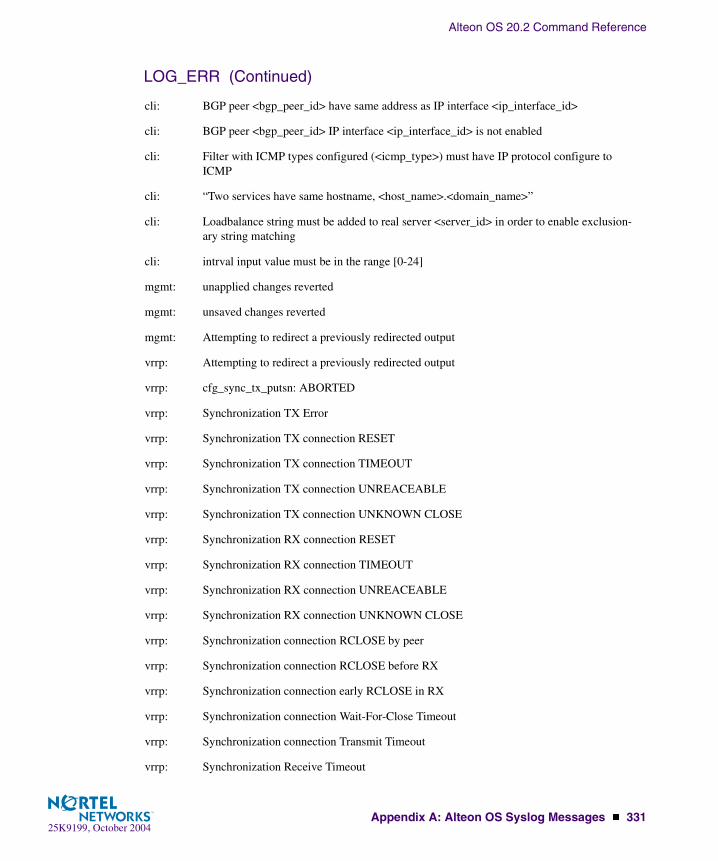
Alteon OS 20.2 Command Reference
Appendix A: Alteon OS Syslog Messages � 33125K9199, October 2004
cli: BGP peer <bgp_peer_id> have same address as IP interface <ip_interface_id>
cli: BGP peer <bgp_peer_id> IP interface <ip_interface_id> is not enabled
cli: Filter with ICMP types configured (<icmp_type>) must have IP protocol configure to ICMP
cli: “Two services have same hostname, <host_name>.<domain_name>”
cli: Loadbalance string must be added to real server <server_id> in order to enable exclusion-ary string matching
cli: intrval input value must be in the range [0-24]
mgmt: unapplied changes reverted
mgmt: unsaved changes reverted
mgmt: Attempting to redirect a previously redirected output
vrrp: Attempting to redirect a previously redirected output
vrrp: cfg_sync_tx_putsn: ABORTED
vrrp: Synchronization TX Error
vrrp: Synchronization TX connection RESET
vrrp: Synchronization TX connection TIMEOUT
vrrp: Synchronization TX connection UNREACEABLE
vrrp: Synchronization TX connection UNKNOWN CLOSE
vrrp: Synchronization RX connection RESET
vrrp: Synchronization RX connection TIMEOUT
vrrp: Synchronization RX connection UNREACEABLE
vrrp: Synchronization RX connection UNKNOWN CLOSE
vrrp: Synchronization connection RCLOSE by peer
vrrp: Synchronization connection RCLOSE before RX
vrrp: Synchronization connection early RCLOSE in RX
vrrp: Synchronization connection Wait-For-Close Timeout
vrrp: Synchronization connection Transmit Timeout
vrrp: Synchronization Receive Timeout
LOG_ERR (Continued)

Alteon OS 20.2 Command Reference
332 � Appendix A: Alteon OS Syslog Messages25K9199, October 2004
vrrp: Synchronization Receive UNKNOWN Timeout
vrrp: Sync transmit in progress … cannot start Sync
vrrp: Sync receive in progress … cannot start Sync
vrrp: Sync already in progress … cannot start Sync
vrrp: Config Sync route find error
vrrp: Config Sync tcp_open error
vrrp: Config Synchronization Timeout - Resuming Console thread
vrrp: “<""apply""|""save""> is issued by another user. Try later”
vrrp: new configuration did not validate (rc = )
vrrp: new configuration did not apply (rc = )
vrrp: new configuration did not save (rc = )
vrrp: Sync config apply error
vrrp: Restoring Current Config
vrrp: Sync rx tcp open error
vrrp: Sync Version/Password Failed-No Version/Password Line
vrrp: Sync Version Failed - peer:%s config:%s
vrrp: Sync Password Failed-Bad Password
vrrp: Sync receive already in progress … cannot start Sync receive
vrrp: Sync transmit in progress … cannot start Sync receive
LOG_ERR (Continued)

Alteon OS 20.2 Command Reference
Appendix A: Alteon OS Syslog Messages � 33325K9199, October 2004
LOG_NOTICE
system: internal power supply ok
system: redundant power supply present and ok
system: temperature ok
system: fan ok
system: rebooted <last_reset_information>
system: rebooted <last_reset_information> administrator logged in
mgmt: boot config block changed
mgmt: boot image changed
mgmt: switch reset from CLI
mgmt: syslog host changed to <ip_address>
mgmt: syslog host changed to this host
mgmt: second syslog host changed to <ip_address>
mgmt: second syslog host changed to this host
mgmt: Next boot will use active config block
mgmt: user password changed
mgmt: SLB operator password changed
mgmt: L4 operator password changed
mgmt: operator password changed
mgmt: SLB administrator password changed
mgmt: L4 administrator password changed
mgmt: administrator password changed
ssh: scp <login_level> login
ssh: “scp <login_level> <""connection closed""|""idle timeout""|""logout"">”
mgmt: RADIUS server timeouts
mgmt: Failed login attempt via TELNET from host %s
mgmt: PASSWORD FIX-UP MODE IN USE
mgmt: <login_level> login on Console

Alteon OS 20.2 Command Reference
334 � Appendix A: Alteon OS Syslog Messages25K9199, October 2004
mgmt: “<login_level> <""idle timeout""|""logout""> from Console”
mgmt: PANIC command from CLI
port_mirr: “port mirroring is <""enabled""|""disabled"">”
vlan: Default VLAN can not be deleted
mgmt: <login_level> login from host <ip_address>
mgmt: “<login_level> <""connection closed""|""idle timeout""|""logout""> from”
IP “default gateway <ip_address> <""enabled""|""disabled"">”
IP default gateway <ip_address> operational
vrrp: virtual router <ip_address> is now master
vrrp: virtual router <ip_address> is now backup
slb: “backup server <ip_address> <""enabled""|""diabled""> for real server <server_id>”
slb: “backup server <ip_address> <""enabled""|""disabled""> for real server group <group_id>”
slb: “backup group server <ip_address> <""enabled""|""disabled""> for real server group group_id>”
slb: “overflow server <ip_address> <""enabled""|""disabled""> for real server <server_id>”
slb: “overflow server <ip_address> <""enabled""|""disabled""> for real server group <group_id>”
slb: “overflow group server <ip_address> <""enabled""|""disabled""> for real server group <group_id>”
slb: real server <ip_address> operational
slb: real service <ip_address:real_port> operational
slb: No services are available for Virtual Server <virtual_server>
slb: Services are available for Virtual Server <virtual_server>
bgp: session established with <BGP_peer_ip_address>
LOG_NOTICE (Continued)

Alteon OS 20.2 Command Reference
Appendix A: Alteon OS Syslog Messages � 33525K9199, October 2004
LOG_INFO
SYSTEM: bootp response from <ip_address>
mgmt: new configuration applied
mgmt: new configuration saved
mgmt: unsaved changes reverted
mgmt: Could not revert unsaved changes
mgmt: " <image1|image2> downloaded from host <ip_address>, file <file_name> <software_version>"
mgmt: serial EEPROM downloaded from host <ip_address> file <file_name>
ssh: scp <login_level> login
ssh: " scp <login_level> <""connection closed""|""idle timeout""|""logout"">"
mgmt: <login_level> login on Console
mgmt: " <login_level> <""idle timeout""|""logout""> from Console"
mgmt: <login_level> login from host <ip_address>
mgmt: " <login_level> <""connection closed""|""idle timeout""|""logout""> from Telnet/SSH."
ssh: server key autogen starts
ssh: server key autogen completes
ssh: server key autogen timer timeouts
vrrp: new synch configuration applied
vrrp: new synch configuration saved
vrrp: Synchronizing from <host_name>
vrrp: Synchronizing to <host_name>
vrrp: Config Synchronization Transmit Successful
vrrp: Config Synchronization Receive Successful
vrrp: new configuration VALIDATED

Alteon OS 20.2 Command Reference
336 � Appendix A: Alteon OS Syslog Messages25K9199, October 2004

25K9199, October 2004337
APPENDIX BAlteon OS SNMP Agent
The Alteon OS SNMP agent supports SNMP Version 1. Security is provided through SNMP community strings. The default community strings are “public” for SNMP GET operation and “private” for SNMP SET operation. The community string can be modified only through the Command Line Interface (CLI). Alteon WebSystems is registered as Vendor 1872. Detailed SNMP MIBs and trap definitions of the Alteon OS SNMP agent can be found in the following Alteon OS enterprise MIB documents:
� Altroot.mib -
� AOSSwitch.mib
� AOSPhysical.mib
� AOSNetwork.mib
� AOSLayer4.mib
� AOSLayer7.mib
� AOSTrap.mib
Users may specify up to two trap hosts for receiving SNMP Traps. The agent will send the SNMP Trap to the specified hosts when appropriate. Traps will not be sent if there is no host specified.
Alteon OS SNMP agent supports the following standard MIBs:
� RFC 1213 - MIB II (System, Interface, Address Translation, IP, ICMP, TCP, UDP, SNMP Groups)
� RFC 1573 - MIB II Extension (IFX table)
� RFC 1643 - EtherLike MIB
� RFC 1493 - Bridge MIB
� RFC 1757 - RMON MIB (Statistics, History, Alarm, Event Groups)
� RFC 1850 for OSPF
� RFC 1657 for BGP
� RFC 2037

Alteon OS 20.2 Command Reference
338 � Appendix B: Alteon OS SNMP Agent25K9199, October 2004
Alteon OS SNMP agent supports the following generic traps as defined in RFC 1215:
� ColdStart
� WarmStart
� LinkDown
� LinkUp
� AuthenticationFailure
The SNMP agent also supports two Spanning Tree traps as defined in RFC 1493:
� NewRoot
� TopologyChange
The following are the enterprise SNMP traps supported in Alteon OS:
Table 10-10 Alteon OS-Supported Enterprise SNMP Traps
Trap Name Description
altSwDefGwUp Signifies that the default gateway is alive.
altSwDefGwDown Signifies that the default gateway is down.
altSwDefGwInService Signifies that the default gateway is up and in service
altSwDefGwNotInService Signifies that the default gateway is alive but not in service
altSwSlbRealServerUp Signifies that the real server is up and operational
altSwSlbRealServerDown Signifies that the real server is down and out of service
altSwSlbRealServerMaxCon-nReached
Signifies that the real server has reached maximum connections
altSwSlbBkupRealServerAct Signifies that the backup real server is activated due to availablity of the primary real server
altSwSlbBkupRealServerDeact Signifies that the backup real server is deactivated due to the primary real server is available
altSwSlbBkupRealServerActOver-flow
Signifies that the backup real server is deactivated due to the primary real server is overflowed
altSwSlbBkupRealServerDeac-tOverflow
Signifies that the backup real server is deactivated due to the primary real server is out from overflow situa-tion

Alteon OS 20.2 Command Reference
Appendix B: Alteon OS SNMP Agent � 33925K9199, October 2004
altSwfltFilterFired Signifies that the packet received on a switch port matches the filter rule
altSwSlbRealServerServiceUp Signifies that the service port of the real server is up and operational
altSwSlbRealServerServiceDown Signifies that the service port of the real server is down and out of service
altSwVrrpNewMaster The newMaster trap indicates that the sending agent has tran-sitioned to ’Master’ state.
altSwVrrpNewBackup The newBackup trap indicates that the sending agent has transitioned to ’Backup’ state.
altSwVrrpAuthFailure A vrrpAuthFailure trap signifies that a packet has been received from a router whose authentication key or authenti-cation type conflicts with this router’s authentication key or authentication type. Implementation of this trap is optional.
altSwLoginFailure A altSwLoginFailure trap signifies that someone failed to enter a valid username/password combination.
altSwSlbSynAttack A altSwSlbSynAttack trap signifies that a SYN attack has been detected.
altSwTcpHoldDown A altSwTcpHoldDown trap signifies that new TCP connec-tion requests from a particular client will be blocked for a pre-determined amount of time since the rate of new TCP connections from that client has reached a pre-determined threshold.
altSwTempExceedThreshold A altSwTempExceedThreshold trap signifies that the switch temperature has exceeded maximum safety limits.
Table 10-10 Alteon OS-Supported Enterprise SNMP Traps
Trap Name Description

Alteon OS 20.2 Command Reference
340 � Appendix B: Alteon OS SNMP Agent25K9199, October 2004
Working with Switch Images and Configuration Files
This section describes how to use MIB calls to work with switch images and configuration files. You can use a standard SNMP tool to perform the actions, using the MIBs listed in Table 10-11.
The examples in this section use the MIB name, but you can also use the OID.
Table 10-11 lists the MIBS used to perform operations associated with the GbESM Switch Image and Configuration files. These MIBS are contained within in the file “aosswitch.mib”
The following SNMP actions can be performed using the MIBs listed in Table 10-11.
� Load a new Switch image (boot or running) from a TFTP server
� Load a previously saved switch configuration from a TFTP server
� Save the switch configuration to a TFTP server
� Save a switch dump to a TFTP server
Table 10-11 MIBs for Switch Image and Configuration Files
MIB Name MIB IOD
aqTftpServer 1.3.6.1.4.1872.2.5.1.1.7.1
aqTftpImage 1.3.6.1.4.1872.2.5.1.1.7.2
aqTftpImageFileName 1.3.6.1.4.1872.2.5.1.1.7.3
aqTftpCfgFileName 1.3.6.1.4.1872.2.5.1.1.7.4
aqTftpDumpFileName 1.3.6.1.4.1872.2.5.1.1.7.5
aqTftpAction 1.3.6.1.4.1872.2.5.1.1.7.6
aqTftpLastActionStatus 1.3.6.1.4.1872.2.5.1.1.7.7
aqTftpPort 1.3.6.1.4.1872.2.5.1.1.7.8

Alteon OS 20.2 Command Reference
Appendix B: Alteon OS SNMP Agent � 34125K9199, October 2004
Loading a new switch imageTo load a new switch image with the name “MyNewImage-1.img” into image2, follow the steps below. This example assumes you have a TFTP server at 192.168.10.10.
1. Set the TFTP server address where the switch image resides:
Set aqTftpServer.0 “192.168.10.10”
2. Set the area where the new image will be loaded:
Set aqTftpImage.0 “image2”
3. Set the name of the image:
Set aqTftpImageFileName.0 “MyNewImage-1.img”
4. Set the port for the TFTP data transfer. Enter 1 to perform the transfer across the data port. Enter 2 to perform the transfer across the management port:
Set aqTftpPort.0 “1”
5. Initiate the transfer. To transfer a switch image, enter 2 (gtimg):
Set aqTftpAction.0 “2”
Loading a saved switch configurationTo load a saved switch configuration with the name “MyRunningConfig.cfg” into the switch, follow the steps below. This example assumes you have a TFTP server at 192.168.10.10.
1. Set the TFTP server address where the switch Configuration File resides:
Set aqTftpServer.0 “192.168.10.10”
2. Set the name of the configuration file:
Set aqTftpCfgFileName.0 “MyRunningConfig.cfg”
3. Set the port for the TFTP data transfer. Enter 1 to perform the transfer across the data port. Enter 2 to perform the transfer across the management port.
Set aqTftpPort.0 “1”
4. Initiate the transfer. To restore a running configuration, enter 3:
Set aqTftpAction.0 “3”

Alteon OS 20.2 Command Reference
342 � Appendix B: Alteon OS SNMP Agent25K9199, October 2004
Saving the switch configurationTo save the switch configuration to a TFTP server follow the steps below. This example assumes you have a TFTP server at 192.168.10.10.
1. Set the TFTP server address where the configuration file is saved:
Set aqTftpServer.0 “192.168.10.10”
2. Set the name of the configuration file:
Set aqTftpCfgFileName.0 “MyRunningConfig.cfg”
3. Set the port for the TFTP data transfer. Enter 1 to perform the transfer across the data port. Enter 2 to perform the transfer across the management port.
Set aqTftpPort.0 “1”
4. Initiate the transfer. To save a running configuration file, enter 4:
Set aqTftpAction.0 “4”
Saving a switch dumpTo save a switch dump to a TFTP, follow the steps below. This example assumes you have a TFTP server at 192.168.10.10.
1. Set the TFTP server address where the configuration will be saved:
Set aqTftpServer.0 “192.168.10.10”
2. Set the name of dump file:
Set aqTftpDumpFileName.0 “MyDumpFile.dmp”
3. Set the port for the TFTP data transfer. Enter 1 to perform the transfer across the data port. Enter 2 to perform the transfer across the management port.
Set aqTftpPort.0 “1”
4. Initiate the transfer. To save a dump file, enter 5:
Set aqTftpAction.0 “5”
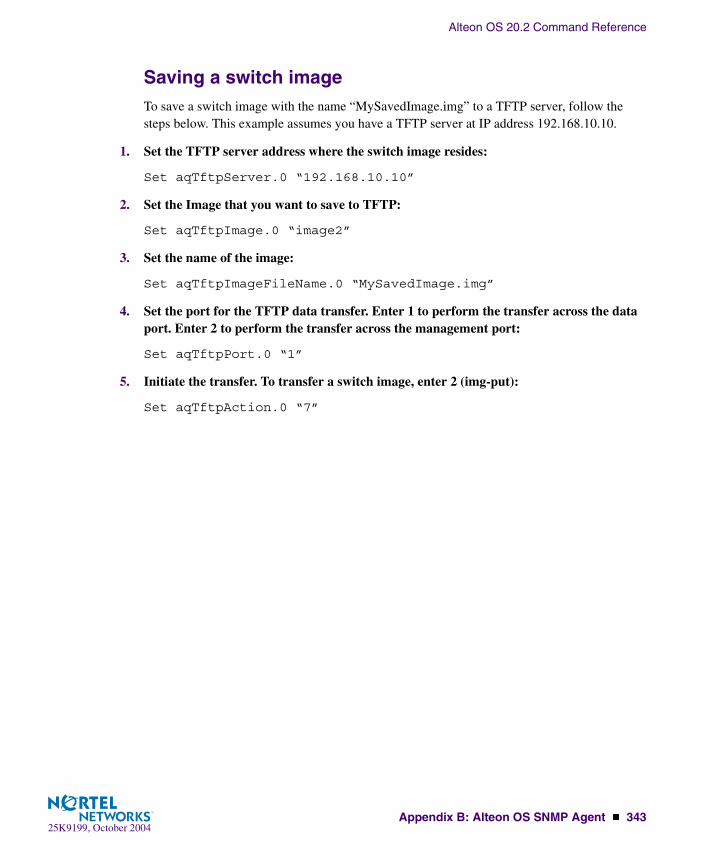
Alteon OS 20.2 Command Reference
Appendix B: Alteon OS SNMP Agent � 34325K9199, October 2004
Saving a switch imageTo save a switch image with the name “MySavedImage.img” to a TFTP server, follow the steps below. This example assumes you have a TFTP server at IP address 192.168.10.10.
1. Set the TFTP server address where the switch image resides:
Set aqTftpServer.0 “192.168.10.10”
2. Set the Image that you want to save to TFTP:
Set aqTftpImage.0 “image2”
3. Set the name of the image:
Set aqTftpImageFileName.0 “MySavedImage.img”
4. Set the port for the TFTP data transfer. Enter 1 to perform the transfer across the data port. Enter 2 to perform the transfer across the management port:
Set aqTftpPort.0 “1”
5. Initiate the transfer. To transfer a switch image, enter 2 (img-put):
Set aqTftpAction.0 “7”

Alteon OS 20.2 Command Reference
344 � Appendix B: Alteon OS SNMP Agent25K9199, October 2004

25K9199, October 2004345
Glossary
DIP (Destination IP Address)
The destination IP address of a frame.
Dport (Destination Port)
The destination port (application socket: for example, http-80/https-443/DNS-53)
NAT (Network Address Translation)
Any time an IP address is changed from one source IP or destination IP address to another address, network address translation can be said to have taken place. In general, half NAT is when the destination IP or source IP address is changed from one address to another. Full NAT is when both addresses are changed from one address to another. No NAT is when neither source nor destination IP addresses are translated. Virtual server-based load balancing uses half NAT by design, because it translates the destination IP address from the Virtual Server IP address, to that of one of the real servers.
Preemption In VRRP, preemption will cause a Virtual Router that has a lower priority to go into backup should a peer Virtual Router start advertising with a higher priority.
Priority In VRRP, the value given to a Virtual Router to determine its ranking with its peer(s). Min-imum value is 1 and maximum value is 254. Default is 100. A higher number will win out for master designation.
Proto (Protocol) The protocol of a frame. Can be any value represented by a 8-bit value in the IP header adherent to the IP specification (for example, TCP, UDP, OSPF, ICMP, and so on.)
Real Server Group A group of real servers that are associated with a Virtual Server IP address, or a filter.

Alteon OS 20.2 Command Reference
346 � Glossary25K9199, October 2004
Redirection or Filter-Based Load Balancing
A type of load balancing that operates differently from virtual server-based load balancing. With this type of load balancing, requests are transparently intercepted and “redirected” to a server group. “Transparently” means that requests are not specifically destined for a Vir-tual Server IP address that the switch owns. Instead, a filter is configured in the switch. This filter intercepts traffic based on certain IP header criteria and load balances it.Filters can be configured to filter on the SIP/Range (via netmask), DIP/Range (via net-mask), Protocol, SPort/Range or DPort/Range. The action on a filter can be Allow, Deny, Redirect to a Server Group, or NAT (translation of either the source IP or destination IP address). In redirection-based load balancing, the destination IP address is not translated to that of one of the real servers. Therefore, redirection-based load balancing is designed to load balance devices that normally operate transparently in your network—such as a fire-wall, spam filter, or transparent Web cache.
RIP (Real Server) Real Server IP Address. An IP addresses that the switch load balances to when requests are made to a Virtual Server IP address (VIP).
SIP (Source IP Address)
The source IP address of a frame.
SPort (Source Port) The source port (application socket: for example, HTTP-80/HTTPS-443/DNS-53).
Tracking In VRRP, a method to increase the priority of a virtual router and thus master designation (with preemption enabled). Tracking can be very valuable in an active/active configuration.
You can track the following:
� Vrs: Virtual Routers in Master Mode (increments priority by 2 for each)
� Ifs: Active IP interfaces on the GbE Switch Module (increments priority by 2 for each)
� Ports: Active ports on the same VLAN (increments priority by 2 for each)
� l4pts: Active Layer 4 Ports, client or server designation (increments priority by 2 for each
� reals: healthy real servers (increments by 2 for each healthy real server)
� hsrp: HSRP announcements heard on a client designated port (increments by 10 for each)
VIP (Virtual Server IP Address)
An IP address that the switch owns and uses to load balance particular service requests (like HTTP) to other servers.
VIR (Virtual Interface Router)
A VRRP address that is an IP interface address shared between two or more virtual routers.

Alteon OS 20.2 Command Reference
Glossary � 34725K9199, October 2004
Virtual Router A shared address between two devices utilizing VRRP, as defined in RFC 2338. One vir-tual router is associated with an IP interface. This is one of the IP interfaces that the switch is assigned. All IP interfaces on the GbE Switch Module must be in a VLAN. If there is more than one VLAN defined on the GbE Switch Module, then the VRRP broadcasts will only be sent out on the VLAN of which the associated IP interface is a member.
Virtual Server Load Balancing
Classic load balancing. Requests destined for a Virtual Server IP address (VIP), which is owned by the switch, are load balanced to a real server contained in the group associated with the VIP. Network address translation is done back and forth, by the switch, as requests come and go.Frames come to the switch destined for the VIP. The switch then replaces the VIP and with one of the real server IP addresses (RIP’s), updates the relevant checksums, and forwards the frame to the server for which it is now destined. This process of replacing the destina-tion IP (VIP) with one of the real server addresses is called half NAT. If the frames were not half NAT’ed to the address of one of the RIPs, a server would receive the frame that was destined for it’s MAC address, forcing the packet up to Layer 3. The server would then drop the frame, since the packet would have the DIP of the VIP and not that of the server (RIP).
VRID (Virtual Router Identifier)
In VRRP, a value between 1 and 255 that is used by each virtual router to create its MAC address and identify its peer for which it is sharing this VRRP address. The VRRP MAC address as defined in the RFC is 00-00-5E-00-01-{VRID}. If you have a VRRP address that two switches are sharing, then the VRID number needs to be identical on both switches so each virtual router on each switch knows whom to share with.
VRRP (Virtual Router Redundancy Protocol)
A protocol that acts very similarly to Cisco’s proprietary HSRP address sharing protocol. The reason for both of these protocols is so devices have a next hop or default gateway that is always available. Two or more devices sharing an IP interface are either advertising or listening for advertisements. These advertisements are sent via a broadcast message to an address such as 224.0.0.18.With VRRP, one switch is considered the master and the other the backup. The master is always advertising via the broadcasts. The backup switch is always listening for the broad-casts. Should the master stop advertising, the backup will take over ownership of the VRRP IP and MAC addresses as defined by the specification. The switch announces this change in ownership to the devices around it by way of a Gratuitous ARP, and advertise-ments. If the backup switch didn’t do the Gratuitous ARP the Layer 2 devices attached to the switch would not know that the MAC address had moved in the network. For a more detailed description, refer to RFC 2338.
VSR (Virtual Server Router)
A VRRP address that is a shared Virtual Server IP address. VSR is Alteon WebSystems’ proprietary extension to the VRRP specification. The switches must be able to share Vir-tual Server IP addresses, as well as IP interfaces. If they didn’t, the two switches would fight for ownership of the Virtual Server IP address, and the ARP tables in the devices around them would have two ARP entries with the same IP address but different MAC addresses.

Alteon OS 20.2 Command Reference
348 � Glossary25K9199, October 2004

25K9199, October 2004349
Index
Symbols(MD5).............................................................. 294(SLB real server group option)
content ...................................................... 259/ command.......................................................... 47[ ]....................................................................... 15
Aabbreviating commands (CLI) .............................. 50access control
user........................................................... 179action (SLB filtering option)............................... 275active configuration block .......................... 166, 309active FTP SLB parsing statistics ........................ 143active IP interface.............................................. 244active Layer 4 processing ................................... 244active port
VLAN....................................................... 244active switch configuration
gtcfg ......................................................... 250ptcfg ......................................................... 250restoring .................................................... 250
active switch, saving and loading configuration.... 250add
ARP entry.................................................. 317SLB port option.......................................... 284
addrARP entries................................................ 317IP route tag .................................................. 70
Address Resolution Protocol (ARP)add, delete entries ....................................... 317address list ................................................. 317
administrator account ..................................... 25, 27admpw (system option) ...................................... 181advertisement of virtual IP addresses ................... 214aging
STP bridge option ....................................... 190STP information ........................................... 63
application redirection................................ 254, 275filter states.................................................... 84filters ......................................................... 254within real server groups .............................. 259
apply (global command) ..................................... 165applying configuration changes........................... 165autoconfiguration
link.............................................................. 32auto-negotiation
enable/disable on port ..................................183setup............................................................ 32
autonomous system filter action .......................... 212autonomous system filter path
action ........................................................212as ..............................................................212aspath ........................................................212
Bbackup
SLB real server group option ........................ 261backup configuration block......................... 166, 309backup server activations (SLB statistics) ............ 151banner (system option) ....................................... 168BBI .................................................................... 17

Alteon OS 20.2 Command Reference
350 � Index25K9199, October 2004
BGPconfiguration...............................................224eBGP .........................................................224filters, aggregation configuration ...................229iBGP..........................................................224in route.......................................................227IP address, border router...............................226IP route tag ...................................................70keep-alive time............................................226peer ...........................................................225peer configuration........................................226redistribution configuration...........................228remote autonomous system ...........................226router hops..................................................227
binding failure ...................................................151binding table......................................................268BLOCKING (port state)........................................64boot options menu..............................................305BOOTP...............................................................22
setup (enable/disable).....................................31system option..............................................168
bootstrap protocol ..............................................235Border Gateway Protocol ......................................70
configuration...............................................224Border Gateway Protocol (BGP)
operations-level options................................304BPDU. See Bridge Protocol Data Unit.bridge parameter menu, for STP ..........................188bridge priority......................................................63Bridge Protocol Data Unit (BPDU) ........................63
STP transmission frequency..........................190Bridge Spanning-Tree parameters ........................190broadcast
IP route tag ...................................................70IP route type .................................................69
Browser-Based Interface.......................................17
Ccapture dump information to a file .......................321Cisco Ether Channel ...........................................192clear
ARP entries ................................................317dump information ........................................322FDB entry...................................................314routing table................................................318
clearing SLB statistics ........................................152client traffic processing.......................................283command (help) ...................................................47
Command-Line Interface (CLI) ....... 17 to 26, 27, 45commands
abbreviations ................................................ 50conventions used in this manual...................... 15global commands.......................................... 47shortcuts ...................................................... 50stacking ....................................................... 50tab completion.............................................. 50
configurationadministrator password ................................ 181apply changes............................................. 165default gateway interval, for health checks ..... 203default gateway IP address ........................... 203dump command .......................................... 249effect on Spanning-Tree Protocol .................. 165flow control................................................ 183Gigabit Ethernet.......................................... 181IP static route ............................................. 205Layer 4 administrator password .................... 180operating mode........................................... 183port link speed ............................................ 183port mirroring............................................. 184port trunking .............................................. 192route cache................................................. 207save changes .............................................. 165setup ......................................................... 249setup command........................................... 249switch IP address ........................................ 202TACACS+................................................. 172user password............................................. 180view changes.............................................. 165VLAN default (PVID) ................................. 181VLAN IP interface...................................... 202VLAN tagging............................................ 182VRRP........................................................ 236
configuration blockactive ........................................................ 309backup....................................................... 309factory....................................................... 309selection .................................................... 309
configuration menu............................................ 163configuring routing information protocol ............. 213connecting
via console ................................................... 18connection timeout (Real Server Menu option)..... 268console port
connecting ................................................... 18content
SLB real server group option........................ 259
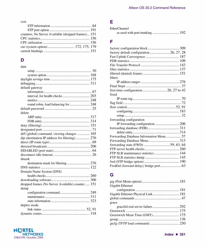
Alteon OS 20.2 Command Reference
Index � 35125K9199, October 2004
costSTP information ........................................... 64STP port option .......................................... 191
counters, No Server Available (dropped frames)... 151CPU statistics.................................................... 156CPU utilization ................................................. 156cur (system option) ............................ 172, 175, 179current bindings ................................................ 151
Ddate
setup ........................................................... 30system option ............................................. 168
daylight savings time ......................................... 175debugging......................................................... 311default gateway
information .................................................. 67interval, for health checks ............................ 203metrics ...................................................... 248round robin, load balancing for ..................... 248
default password ................................................. 25delete
ARP entry.................................................. 317FDB entry.................................................. 314
deny (filtering) .................................................. 151designated port. ................................................... 71diff (global) command, viewing changes ............. 165dip (destination IP address for filtering)............... 276direct (IP route type)............................................ 69directed broadcasts ............................................ 206DISABLED (port state)........................................ 64disconnect idle timeout ........................................ 26dmask
destination mask for filtering........................ 276DNS statistics ................................................... 122Domain Name System (DNS)
health checks.............................................. 260downloading software........................................ 306dropped frames (No Server Available) counter ..... 151dump
configuration command ............................... 249maintenance............................................... 311state information......................................... 323
duplex modelink status .............................................. 52, 91
dynamic routes.................................................. 318
EEtherChannel
as used with port trunking ............................192
Ffactory configuration block................................. 309factory default configuration..................... 26, 27, 28Fast Uplink Convergence ................................... 187FDB statistics .................................................... 109File Transfer Protocol ........................................ 143filter statistics .................................................... 137filtered (denied) frames ...................................... 151filters
IP address ranges ........................................ 276Final Steps .......................................................... 37first-time configuration..........................26, 27 to 42fixed
IP route tag................................................... 70flag field ............................................................. 72flow control................................................... 52, 91
configuring................................................. 183setup............................................................ 32
forwarding configurationIP forwarding configuration.......................... 206
forwarding database (FDB)................................. 311delete entry................................................. 314
Forwarding Database Information Menu ................ 57Forwarding Database Menu ................................ 313forwarding state (FWD) ........................... 59, 63, 64FTP server health checks .................................... 260FTP SLB maintenance statistics .......................... 144FTP SLB statistics dump .................................... 145fwd (STP bridge option) ..................................... 190FwdDel (forward delay), bridge port...................... 63
Ggig (Port Menu option) ....................................... 181Gigabit Ethernet
configuration .............................................. 181Gigabit Ethernet Physical Link............................181global commands................................................. 47grace
graceful real server failure ............................292Greenwich ........................................................175Greenwich Mean Time (GMT)............................175group................................................................ 136gtcfg (TFTP load command) ............................... 250
Alteon OS 20.2 Command Reference
352 � Index25K9199, October 2004
Hhash metric ........................................................263health checks .....................................................256
default gateway interval, retries .....................203IDSLB .......................................................260layer information ...........................................84parameters for most protocols .......................260redirection (rport) ........................................275retry, number of failed health checks..............203script..........................................................295WAP..........................................................296
helloSTP information ............................................63
help ....................................................................47host routes .........................................................214Hot Standby Router on VLAN (HSRV)
use with VLAN-tagged environment..............241VRRP priority increment value .....................248
Hot Standby Router Protocol (HSRP)priority increment value for L4 client ports .....247use with VRRP....................................241, 245VRRP priority increment value .....................247
Hot Standby Router VLAN (HSRV)use with VRRP............................................245
hot-standby failover............................................242HP-OpenView .....................................................17hprompt
system option..............................................168HSRP. See Hot Standby Router Protocol.HSRV. See Hot Standby Router Protocol.HTTP
application health checks ..............................260HTTP health checks
on any port (aphttp)......................................294
IICMP statistics...................................................122idle timeout
overview ......................................................26IDSLB health checks ..........................................260IEEE standards
802.1d Spanning-Tree Protocol ...............63, 188IGMP statistics ..................................................124image
downloading ...............................................306software, selecting .......................................307
IMAP server health checks..................................260
imask (IP address mask)..................................... 291incorrect VIPs (statistic) ..................................... 151incorrect Vports (dropped frames counter) ........... 151indirect (IP route type) ......................................... 69Information
IGMP Information ........................................ 80IGMP Multicast Router Information. 80, 81, 320,
321Trunk Group Information............................... 64
Information Menu................................................ 51Interface change stats ......................................... 116interface statistics .............................................. 125IP address ........................................................... 34
ARP information .......................................... 71BOOTP ....................................................... 22configuring default gateway ......................... 203filter ranges ................................................ 276IP interface................................................... 34local route cache ranges ............................... 207
IP address mask (mmask) ................................... 179IP address mask for SLB .................................... 291IP configuration via setup..................................... 34IP forwarding .................................................... 233
directed broadcasts...................................... 206local networks for route caching ................... 206
IP forwarding information .................................... 67IP Information Menu ..................................... 67, 82IP interface ....................................................... 202
active ........................................................ 244configuring address ..................................... 202configuring VLANs .................................... 202
IP interfaces .................................................. 34, 69information .................................................. 67IP route tag .................................................. 70priority increment value (ifs) for VRRP ......... 247
IP network filter configuration ............................ 208IP port configuration.......................................... 233IP Route Manipulation Menu.............................. 317IP routing............................................................ 34
tag parameters .............................................. 70IP Static Route Menu ......................................... 205IP statistics........................................................ 117IP subnet mask .................................................... 35IP switch processor statistics............................... 111
Ll4apw (L4 administrator system option) ............... 180LACP............................................................... 196
Alteon OS 20.2 Command Reference
Index � 35325K9199, October 2004
Layer 2 Menu...................................................... 56Layer 3 Menu...................................................... 66Layer 4
administrator account .................................... 25Layer 4 processing
active ........................................................ 244layer 7 SLB maintenance statistics ...................... 140layer 7 SLB string statistics ................................ 139layer7 redirection statistics ................................. 138LDAP version ................................................... 294LEARNING (port state) ................................. 63, 64least connections (SLB Real Server metric) ......... 263link
speed, configuring....................................... 183Link Aggregation Control Protocol ..................... 196link status ........................................................... 52
command..................................................... 91duplex mode .......................................... 52, 91port speed .............................................. 52, 91
Link Status Information ....................................... 91linkt (SNMP option) .......................................... 178LISTENING (port state)....................................... 64lmask (routing option).......................................... 67lnet (routing option)............................................. 67local (IP route type) ............................................. 69local network for route caching........................... 206local route cache
IP address ranges for ................................... 207log
syslog messages.......................................... 169
MMAC (media access control) address.. 53, 54, 57, 71,
313switch location ............................................. 22
Main Menu ......................................................... 45Command-Line Interface (CLI) ...................... 26summary...................................................... 46
Maintenance Menu ............................................ 311management module............................................ 18Management Processor (MP).............................. 315
display MAC address .............................. 53, 54manual style conventions ..................................... 15martian
IP route tag (filtered) ..................................... 70IP route type (filtered out) .............................. 69
maskIP interface subnet address ........................... 202
mation ................................................................ 64MaxAge (STP information) .................................. 63mcon (maximum connections) .................... 151, 261MD5 cryptographic authentication ...................... 217MD5 key........................................................... 220media access control. See MAC address.metric
SLB real server group option ........................ 259metrics, SLB ..................................................... 262minimum misses (SLB real server metric) ............ 262Miscellaneous Debug Menu................................ 315mmask
system option .............................................179mnet
system option .............................................179monitor port ...................................................... 185mp
packet........................................................154MP. See Management Processor.multicast
IP route type................................................. 69mxage (STP bridge option) ................................. 190
Nnbr change statistics ........................................... 115Network Address Translation (NAT)
filter action................................................. 275network management ........................................... 17non TCP/IP frames ............................................ 151notice ............................................................... 168NTP server menu............................................... 174NTP synchronization.......................................... 175NTP time zone .................................................. 175
Ooctet counters .................................................... 135online help .......................................................... 47operating mode, configuring ............................... 183operations menu ................................................ 299operations-level BGP options.............................. 304operations-level IP options ................................. 303Operations-Level Port Options ............................301operations-level SLB options .............................. 302operations-level VRRP options ........................... 303
Alteon OS 20.2 Command Reference
354 � Index25K9199, October 2004
ospfarea index ...........................................215, 216authentication key........................................220configuration...............................................215cost of the selected path................................219cost value of the host....................................222dead, declaring a silent router to be down .......219dead, health parameter of a hello packet .........221export.........................................................223fixed routes.................................................225general .......................................................113global.........................................................113hello, authentication parameter of a hello packet....
221host entry configuration................................222host routes ..................................................215interface .....................................................215interface configuration .................................219link state database........................................216Not-So-Stubby Area ....................................217priority value of the switch interface ..............219range number ..............................................215redistribution menu......................................215route redistribution configuration...................223spf, shortest path first ...................................217stub area.....................................................217summary range configuration........................218transit area ..................................................217transit delay ................................................219type ...........................................................217virtual link ..................................................215virtual link configuration ..............................220virtual neighbor, router ID ............................221
OSPF Database Information ..................................78OSPF general.......................................................75OSPF General Information....................................76OSPF Information ................................................75OSPF Information Route Codes.............................79OSPF statistics...................................................112overflow server activations..................................151overflow servers.................................................256
Ppanic
command....................................................323switch (and Maintenance Menu option) ..........311
parameterstag............................................................... 70type............................................................. 69
Passive FTP SLB Parsing Statistics ..................... 144Password
user access control ...................................... 180password
administrator account .................................... 25default ......................................................... 25L4 administrator account................................ 25user account ................................................. 24VRRP authentication................................... 246
passwords ........................................................... 24peer proxy IP address (PIP) configuration ............ 298PeerPIP ............................................................ 298persistent bindings
real server .................................................. 268ping............................................................ 48, 255PIP................................................................... 297poisoned reverse, as used with split horizon ......... 213POP3
server health checks .................................... 260port configuration .............................................. 181Port Fast Forwarding ......................................... 182port flow control. See flow control.Port Menu
configuration options................................... 181configuring Gigabit Ethernet (gig)................. 181
port mirroringconfiguration.............................................. 184
Port number ........................................................ 91port speed ..................................................... 52, 91port states
UNK (unknown)........................................... 59port trunking
description ................................................. 192port trunking configuration................................. 192ports
configuration................................................ 31disabling (temporarily) ................................ 184information .................................................. 92IP status....................................................... 67membership of the VLAN........................ 57, 65priority ........................................................ 63SLB state information.................................... 84STP port priority......................................... 191VLAN ID .............................................. 52, 92
Alteon OS 20.2 Command Reference
Index � 35525K9199, October 2004
preemptionassuming VRRP master routing authority....... 240virtual router ...................................... 239, 243
priorityvirtual router .............................................. 243
priority (STP port option)................................... 191prisrv
primary radius server................................... 171proxies
IP address translation................................... 257proxy IP address (PIP) ......................................... 84proxy IP address (PIP) configuration ................... 297ptcfg (TFTP save command) .............................. 250PVID (port VLAN ID)................................... 52, 92pwd.................................................................... 48
Qquiet (screen display option)................................. 48
RRADIUS
server authentication ................................... 260RADIUS server menu........................................ 171read community string (SNMP option) ................ 177real server
statistics..................................................... 135real server group options
add............................................................ 262real server group SLB configuration.................... 259real server group statistics .................................. 136real server groups
combining servers into................................. 259statistics..................................................... 136
real server SLB configuration ............................. 254real servers
backup....................................................... 261priority increment value (reals) for VRRP...... 247SLB state information ................................... 84
reboot....................................................... 311, 323receive flow control ..................................... 32, 183redir (SLB filtering option)................................. 275reference ports .................................................... 59referenced port .................................................... 71remote monitoring on the port (rmon).................. 301restarting switch setup.......................................... 29retries
radius server............................................... 171
retryhealth checks for default gateway.................. 203
ripIP route tag................................................... 70
RIP. See Routing Information Protocol.round robin
as used in gateway load balancing .................248roundrobin
SLB Real Server metric ............................... 263route
cache configuration ..................................... 207route statistics.................................................... 119router hops ........................................................227routing information protocol
configuration .............................................. 213Routing Information Protocol (RIP)....................... 70
options....................................................... 213poisoned reverse ......................................... 213split horizon ............................................... 213version 1 parameters.................................... 213
rportSLB virtual server option ............................. 267
RTSP SLB statistics........................................... 146rx flow control..................................................... 32Rx/Tx statistics.................................................. 114
Ssave (global command) ...................................... 165
noback option .............................................166save command...................................................309script
health checks .............................................. 295scriptable health checks configuration.................. 295secret
radius server ............................................... 171secsrv
secondary radius server................................ 171Secure Shell ...................................................... 170Server Load Balancing
information .................................................. 84operations-level options ............................... 302real server weights....................................... 255
server load balancingclient traffic processing ................................ 283metrics....................................................... 262port options ................................................ 284server traffic processing ............................... 283
server load balancing configuration options.......... 251
Alteon OS 20.2 Command Reference
356 � Index25K9199, October 2004
Server Load Balancing Maintenance Statistics Menu...142, 143, 150
server port mapping..............................................84server traffic processing ......................................283Session Binding Table ........................................256session identifier ................................................265setup
configuration...............................................249setup command, configuration.............................249setup facility ..................................................26, 27
BOOTP........................................................31IP configuration.............................................34IP subnet mask ..............................................35port auto-negotiation mode .............................32port configuration ..........................................31port flow control............................................32restarting ......................................................29Spanning-Tree Protocol..................................31starting .........................................................28stopping .......................................................29system date ...................................................30system time...................................................30VLAN name .................................................33VLAN tagging ..............................................32VLANs ........................................................33
SFD statisticsmp specific .................................................156
shortcuts (CLI).....................................................50SIP (source IP address for filtering) .....................276SLB filtering option
action.........................................................275SLB Information ..................................................84SLB layer7 statistics ...........................................138SLB real server group health checks
arp .............................................................260dns.............................................................260ftp..............................................................260http ............................................................260icmp ..........................................................260imap ..........................................................260ldap ...........................................................260radius.........................................................260script..........................................................260smtp...........................................................260sslh ............................................................260tcp .............................................................260udpdns .......................................................260wsp............................................................260wtls............................................................260
SLB real server group optionapplication health checking .......................... 260health checking........................................... 260metric........................................................ 259
SLB real server optionbackup....................................................... 256intr (interval) .............................................. 256maxcon (maximum connections) .................. 255name, alias for each real server ..................... 255restr (restore) SLB real server UDP option ..... 256retry .......................................................... 256RIP, real server IP address............................ 255submac ...................................................... 257tmout (time out).......................................... 256weights ...................................................... 255
smasksource mask for filtering .............................. 276
smtp ................................................................. 168SMTP server health checks................................. 260snap traces
buffer ........................................................ 315SNMP .......................................................... 17, 96
HP-OpenView.............................................. 17menu options.............................................. 177set and get access ........................................ 177
SNMP Agent..................................................... 337SNMP statistics ................................................. 158SNMP Support
optional setup for SNMP support .................... 38software
image ........................................................ 306image file and version.............................. 53, 54
SP specific statistics........................................... 156spanning tree
configuration.............................................. 188Spanning-Tree Protocol................................ 64, 165
bridge aging option ..................................... 190bridge parameters........................................ 190bridge priority .............................................. 63port cost option........................................... 191port priority option ...................................... 191root bridge ........................................... 63, 190setup (on/off)................................................ 31switch reset effect ....................................... 310
split horizon ...................................................... 213SSL.................................................................. 268
secure socket layer statistics ......................... 142stacking commands (CLI) .................................... 50starting switch setup ............................................ 28

Alteon OS 20.2 Command Reference
Index � 35725K9199, October 2004
state (STP information) ........................................ 64state information, client system........................... 268static
IP route tag .................................................. 70static route
rem ........................................................... 205static routes
Routing Information Protocol (RIP) .............. 213statis route
add............................................................ 205statistics
group ........................................................ 136management processor ................................ 153
Statistics Menu.................................................... 95stopping switch setup........................................... 29subnet address maskconfiguration
IP subnet address ........................................ 202subnet mask ........................................................ 35subnets ............................................................... 34
IP interface ................................................ 202switch
name and location ................................... 53, 54resetting..................................................... 310
Switch Processor (SP)........................................ 315display trace buffer ..................................... 315
SYN attack detection configuration..................... 293sync ................................................................. 302synchronization
VRRP switch ..................................... 289, 302syslog
system host log configuration ....................... 169system
contact (SNMP option)................................ 177date and time.......................................... 53, 54information .................................................. 54location (SNMP option)............................... 177
System Information ............................................. 53System Maintenance Menu................................. 313
system optionsadmpw (administrator password)................... 181BOOTP ..................................................... 168cur (current system parameters)..... 172, 175, 179date ........................................................... 168hprompt ..................................................... 168l4apw (Layer 4 administrator password)......... 180login banner ............................................... 168mmask....................................................... 179mnet .......................................................... 179time........................................................... 168tnet............................................................ 179tnport......................................................... 179usrpw (user password) ................................. 180wport......................................................... 178
system parameters, current.................. 172, 175, 179
Ttab completion (CLI)............................................ 50tacacs ............................................................... 172TACACS+ ........................................................172TCP.................................................................. 111
fragments ........................................... 151, 265health checking using ..................................256health checks .............................................. 260source and destination ports.......................... 274
TCP statistics ............................................ 127, 155Telnet
BOOTP ....................................................... 22configuring switches using ........................... 249
telnetradius server ............................................... 172
Telnet supportoptional setup for Telnet support ..................... 38
text conventions................................................... 15TFTP................................................................ 306
PUT and GET commands ............................250TFTP server ...................................................... 250thash................................................................. 193time
setup............................................................ 30system option .............................................168
timeoutradius server ............................................... 172
timeoutsidle connection ............................................. 26
timers kickoff .................................................... 116

Alteon OS 20.2 Command Reference
358 � Index25K9199, October 2004
tnetsystem option..............................................179
tnportsystem option..............................................179
TPCP (Transparent Proxy Cache Protocol) ...........292trace buffer ........................................................315
Switch Processor .........................................315traceroute ............................................................48Tracking
VRRP ........................................................238transmit flow control ....................................32, 183transparent proxies, when used for NAT...............275trunk group failover............................................192Trunk Group Information......................................64trunk hash..........................................................193trunk hash algorithm...........................................193tx flow control .....................................................32type of area
ospf ...........................................................217type parameters....................................................69typographic conventions, manual...........................15tzone.................................................................175
UUCB statistics ....................................................155UDP .................................................................111
datagrams ...................................................151server status using........................................256source and destination ports ..........................274
UDP statistics ....................................................129unknown (UNK) port state ....................................59Unscheduled System Dump.................................323upgrade, switch software.....................................306URL for health checks ..........................................84user access control configuration .........................179user account.........................................................24usrpw (system option).........................................180Uuencode Flash Dump........................................321
Vverbose ...............................................................48vip
advertisement of virtual IP addresses as HostRoutes ................................................214
IP route tag ...................................................70virtual IP address (VIP) ........................................84virtual port state, SLB information about ................84
virtual routerdescription ................................................. 237master mode............................................... 244priority ...................................................... 243tracking criteria........................................... 240
virtual router groupVRRP priority tracking................................ 242
virtual router group configuration........................ 242virtual router group priority tracking ................... 244Virtual Router Redundancy Protocol (VRRP)
authentication parameters for IP interfaces ..... 246group options (prio)..................................... 243operations-level options ............................... 303password, authentication .............................. 246priority election for the virtual router ............. 238priority tracking options............... 226, 229, 240
Virtual Router Redundancy Protocol configuration236virtual routers
HSRP failover .................................... 241, 245HSRP priority increment value ..................... 247HSRV ....................................................... 245HSRV priority increment value..................... 248increasing priority level of............................ 240incrementing VRRP instance........................ 241master preemption (preem)........................... 243master preemption (prio).............................. 239priority increment values (vrs) for VRRP ....... 247
virtual server SLB statistics ................................ 137virtual servers.................................................... 262
SLB state information.................................... 84statistics..................................................... 137
VLANactive port .................................................. 244configuration.............................................. 198
VLAN taggingport configuration ....................................... 182port restrictions........................................... 199setup ........................................................... 32
VLANs............................................................... 34ARP entry information .................................. 71information .................................................. 65interface....................................................... 35name ..................................................... 57, 65name setup................................................... 33port membership..................................... 57, 65setting default number (PVID)...................... 181setup ........................................................... 33tagging .................................... 32, 52, 92, 199VLAN Number............................................. 65

Alteon OS 20.2 Command Reference
Index � 35925K9199, October 2004
VRID (virtual router ID) ............................ 238, 242VRRP
interface configuration................................. 246master advertisements ................................. 239tracking ..................................................... 238tracking configuration ................................. 247
VRRP Information .............................................. 82VRRP master advertisements
time interval ............................................... 243VRRP statistics ................................................. 121
WWAP
health checks.............................................. 296
WAP health checkwspport...................................................... 296wtlsprt ....................................................... 296
WAP health check configuration ......................... 296WAP SLB statistics ........................................... 148watchdog timer.................................................. 311weights
for SLB real servers..................................... 264setting virtual router priority values ............... 247
wport ................................................................ 178write community string (SNMP option) ............... 177wspport
WAP health check....................................... 296wtlsprt
WAP health check....................................... 296

Alteon OS 20.2 Command Reference
360 � Index25K9199, October 2004