altair procedures (10/7/13)
TRANSCRIPT

1
ALTAIR 14
29Jul15
Name: ________________
Site: ________________

2
Table of Contents Part 1: Mission Overview ............................................................................................................................ 3
Purpose of Flight ...................................................................................................................................... 3 Systems Under Test .................................................................................................................................. 3 Changes From Previous Flights ................................................................................................................ 4 Flight Success Criteria ............................................................................................................................... 4
Part 2: Flight Procedures ............................................................................................................................. 5 Timeline .................................................................................................................................................... 5 Flight Properties Table ............................................................................................................................. 7 P1: T-3 Day Wx Check ............................................................................................................................... 8 P2: T-2 Day Wx Check and MRR ............................................................................................................... 9 P3: T-1 Day Launch Preparations ........................................................................................................... 10 Equipment Checklists ............................................................................................................................. 12 P4: Assembly and Departure ................................................................................................................. 18 P5(L): Arrival and Setup (Launch) .......................................................................................................... 20 P5(R): Arrival and Setup (Recovery) ..................................................................................................... 21 P5(S): Arrival and Setup (Science) ......................................................................................................... 22 P6: Vehicle Assembly and Verification ................................................................................................. 24 P7: Launch .............................................................................................................................................. 28 P8: Flight ................................................................................................................................................ 30 P9: Post Flight Documentation ............................................................................................................. 32 P10: Recovery ....................................................................................................................................... 32
Part 3: Reference ...................................................................................................................................... 33 Site Data ................................................................................................................................................. 33 Frequency List ......................................................................................................................................... 33 Emergency Phone Numbers ................................................................................................................... 34 Personnel and Contact Information ...................................................................................................... 34 Vehicle Flight Properties (from A12) ..................................................................................................... 37

3
Part 1: Mission Overview
Purpose of Flight
The purpose of the ALTAIR 14 flight is to provide an engineering test of all flight and operational
systems and to attempt to procure quantitative science imagery of the new LED diffusive light
source. The two principle systems under test are the science system including telescope
pointing and imaging, and the parafoil recovery system.
The current gondola was developed after the loss of A13 and has never been flown.
Nevertheless, it was designed using previous lessons learned and has been extensively ground
tested, so it offers high confidence of successful operation. The suspension rigging and parafoil
deployment system has been changed dramatically, however, and has only been tested in
tethered flights. Validation of correct deployment is a major objective of this mission.
Some aspects of the descent navigation software have been improved, so it is an objective to
gather flight characteristics data and to develop a workable steering strategy to bring the
parafoil to a landing at the designated recovery site.
The diffusive light source has been tested in the lab and roughly calibrated. Although the
platform may not be fully stable in this flight, obtaining quantitative imagery should be possible,
and is a major objective of the mission.
The SPOT Trace is installed. It is a mission objective to demonstrate its functionality at altitude.
This flight will continue the process of gradually increasing cutdown altitude.
Systems Under Test
Payload:
- Science firmware
- Science protocol
- Diffusive light source
- Parafoil deployment at higher altitude with new rigging.
- Parafoil controllability
- SPOT
Ground Operations:
- Telescope pointing

4
- Science protocol
- Imaging system
- Navigation
Changes From Previous Flights
Payload
- New Version 3 Gondola
- New Science firmware installed
- New control aspects incorporated into firmware
- Backup altitude cutdown enabled
Ground Operations
- Science protocol features added in software
- New procedural strategy for descent
Flight Success Criteria
Flight Vehicle Result
1. Obtain ascent rate of 5.8 m/s +/-0.5 m/s
2. Achieve cutdown at planned altitude
3. Achieve final descent rate of 3 m/s
5. Survive landing with no damage to critical payload systems
7. Achieve controlled steering in descent.
8. Measure steering turn rate.
9. Measure descent rate in turns.
10. Achieve landing within 1 km of selected landing location

5
Science Payload Result
1. Demonstrate science protocol
Ground Operations Result
1. Receive telemetry from launch to descent leg < 500 m
2. Locate and recover payload after landing
3. Obtain quantitative imagery of vehicle in flight
4. Demonstrate usability of flight navigation software
5. Demonstrate effectiveness of strategy for navigation to landing
Part 2: Flight Procedures
Timeline
Mission Time
(DD:HH:MM)
EDT Event
- 03:00:00 Sun P1: T-3 Day Wx Check
- 02:00:00 Mon P2: T-2 Day Wx Check
- 01:00:00 Tue P3: MRR, T-1 Day Launch Preparations
- 00:02:00 0230, Wed P4: Assembly and Departure
- 00:01:30 0300 P5: Arrival and Setup (Launch)
- 00:01:30 0300 P5: Arrival and Setup (Science)
- 00:01:30 0300 P5: Arrival and Setup (Recovery)
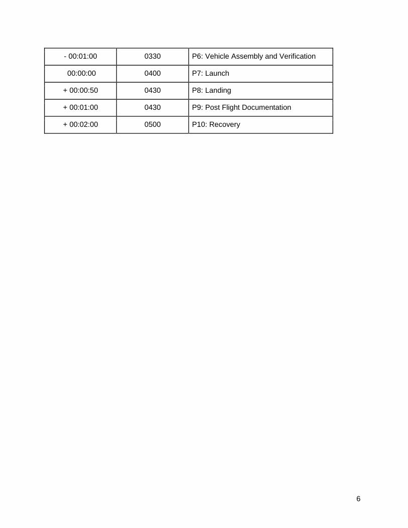
6
- 00:01:00 0330 P6: Vehicle Assembly and Verification
00:00:00 0400 P7: Launch
+ 00:00:50 0430 P8: Landing
+ 00:01:00 0430 P9: Post Flight Documentation
+ 00:02:00 0500 P10: Recovery
7
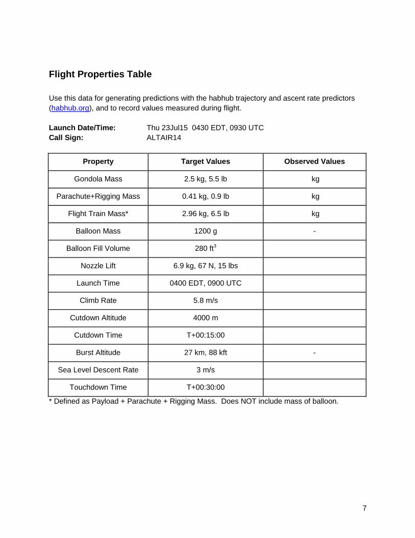
Flight Properties Table
Use this data for generating predictions with the habhub trajectory and ascent rate predictors
(habhub.org), and to record values measured during flight.
Launch Date/Time: Thu 23Jul15 0430 EDT, 0930 UTC
Call Sign: ALTAIR14
Property Target Values Observed Values
Gondola Mass 2.5 kg, 5.5 lb kg
Parachute+Rigging Mass 0.41 kg, 0.9 lb kg
Flight Train Mass* 2.96 kg, 6.5 lb kg
Balloon Mass 1200 g -
Balloon Fill Volume 280 ft3
Nozzle Lift 6.9 kg, 67 N, 15 lbs
Launch Time 0400 EDT, 0900 UTC
Climb Rate 5.8 m/s
Cutdown Altitude 4000 m
Cutdown Time T+00:15:00
Burst Altitude 27 km, 88 kft -
Sea Level Descent Rate 3 m/s
Touchdown Time T+00:30:00
* Defined as Payload + Parachute + Rigging Mass. Does NOT include mass of balloon.

8
P1: T-3 Day Wx Check
__ Predicted ground winds at launch site < 5 mph (4.4 knots) ,
__ Skies at launch site < 20% coverage
__ Ceiling < 20,000 ft
__ Chance of precipitation <10%
__ Obtain preliminary estimates of flight train properties and complete the table below
__ Verify that sufficient helium is available, plus a margin if transport is available
__ Identify prospective launch and recovery sites
__ Obtain any permissions necessary for use of launch or recovery sites.
Property Source Value
Flight Train Mass Measure
Climb rate Habhub Burst Calculator
Balloon Fill Volume Estimate
Nozzle Lift Habhub Burst Calculator
Burst Altitude Habhub Burst Calculator
Cutdown Altitude Flight Properties Table
Sea Level Descent Rate Previous flight data

9
P2: T-2 Day Wx Check and MRR
Wx Check
__ Predicted ground winds at launch site < 5 mph (4.3 knots) , no gusting
__ Skies at launch site < 10% coverage
__ Ceiling > 20,000 ft
__ Chance of precipitation <10%
Mission Readiness Review
__ Confirm all launch and recovery personnel availability for launch window
__ Poll personnel for feasibility of flight
__ Confirm all open issues have been addressed
__ Update all TARGET values in the Flight Properties Table
__ Identify any remaining issues to be resolved before launch in the table below
Issue Resolved?
Software discrepancies as listed
Firmware discrepancies as listed
Gondola issues as listed
Set Altitude Cutdown value
Set DNT Power Level
Rehearse Rigging Procedure
10
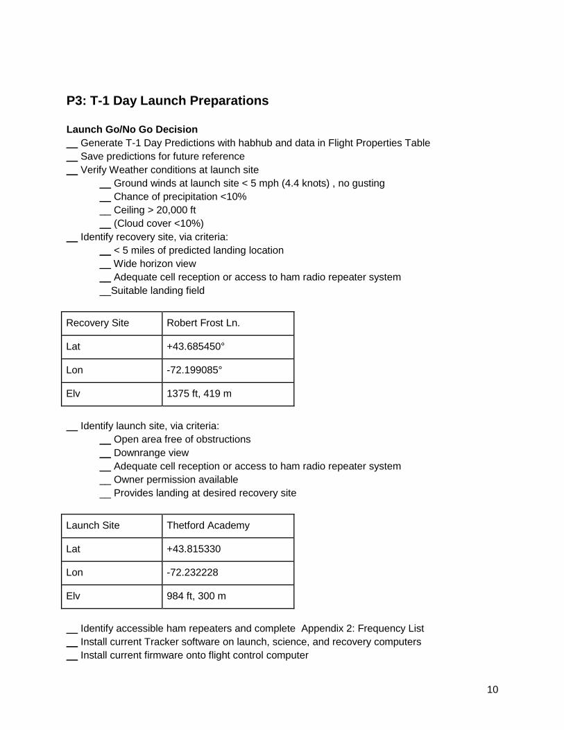
P3: T-1 Day Launch Preparations
Launch Go/No Go Decision
__ Generate T-1 Day Predictions with habhub and data in Flight Properties Table
__ Save predictions for future reference
__ Verify Weather conditions at launch site
__ Ground winds at launch site < 5 mph (4.4 knots) , no gusting
__ Chance of precipitation <10%
__ Ceiling > 20,000 ft
__ (Cloud cover <10%)
__ Identify recovery site, via criteria:
__ < 5 miles of predicted landing location
__ Wide horizon view
__ Adequate cell reception or access to ham radio repeater system
__Suitable landing field
Recovery Site Robert Frost Ln.
Lat +43.685450°
Lon -72.199085°
Elv 1375 ft, 419 m
__ Identify launch site, via criteria:
__ Open area free of obstructions
__ Downrange view
__ Adequate cell reception or access to ham radio repeater system
__ Owner permission available
__ Provides landing at desired recovery site
Launch Site Thetford Academy
Lat +43.815330
Lon -72.232228
Elv 984 ft, 300 m
__ Identify accessible ham repeaters and complete Appendix 2: Frequency List
__ Install current Tracker software on launch, science, and recovery computers
__ Install current firmware onto flight control computer

11
Payload Preparation
Verify:
__ Temperature probes secured with kapton tape
__ RF beacon antenna connector is tightened down
__ Telemetry antenna connector is tightened down
__ Spray interior with compressed air to remove dust and debris
__ Steering strings clear and seated
__ Strain relief to DNT UHF connection to flight control board
__ (Black paper covering installed)
__ Install foam covering on gondola
__ Orange duct tape covering installed
__ Mission patches and return notification installed
Payload Life Test
__ Assemble and power up the recovery ground station (see P5-R for procedures)
__ Set gondola master power switch ON
__ Verify payload telemetry
__ Data streaming
__ GPS Fix
__ AHRS
__ All Sensors
__ Science
__ Cut down
__ Steering
__ RF Beacon
__ SET GONDOLA MASTER POWER SWITCH OFF. TAPE DOWN.
__ PLUG IN CHARGERS TO GONDOLA CHARGE TERMINALS AND LEAVE CHARGING
__ Verify video camera data storage empty
__ Charge video camera
__ Disassemble recovery ground station used for payload life test
Video Camera Setup
__ Verify camera charged (solid green light when on charger)
Pack for Flight
__ Measure the following OBSERVED values; enter in Flight Properties Table
__ Gondola Mass
__ Parachute and Rigging Mass
__ Compute the Flight Train Masses and record in Flight Properties Table
__ Re-compute climb and descent rates, record in Flight Properties Table
__ Prepare fresh suspension rigging and spreader bar
__ Roll flight harness on spreader bar
__ Complete Equipment Checklist on following pages

12
Equipment Checklists
LAUNCH 0: Unboxed
__ Gondola with Telemetry Antenna
__ Gondola Cap (including switch plug)
__ Spreader bar with suspension rigging attached
__ Tarp
__ Launch Frame
__ Helium Cylinders (2) 150SCF
LAUNCH 1: Inflation
__ 30 ft Release Line
__ Helium Regulator Wrench
__ Long-nose Pliers
__ Box: Balloons
__ 1200g Balloons in plastic bags (2)
__ Box: Gas Handling
__ Regulator
__ Tubing
__ Inflation Nozzle
__ Bag 1
__ Zip Ties (4)
__ Tie-off strings (5)
__ Wire Cutters
__ Bag 2
__ Nitrile Gloves
__ Paper Towels

13
LAUNCH 2: Radio
__ Ground Station Radio (Canary) (including transmission cable)
__ 6-Element Yagi
__ Radio Tripod
__ DNT Power Supply
__ RJ45 Cable (Green, 15 ft)
(Ham radio equipment)
LAUNCH 3: Computer (Green Case)
__ Operations Computer (Gateway--Elsie)
__ Computer Power Supply
__ PS/2 Mouse
__ RJ-45 Release Key
__ Bag 1
__ 6-pin RJ45-DB9 Adapter
__ Keyspan
__ USB Cable
__ (USB Hub)
LAUNCH 4: Power
__ Battery (12 V), or confirmed car outlet available
__ Battery clips
__ Cigarette lighter adapter
__ 12-120 V Power Inverter (Duracell)
__ 50-ft Orange Extension Cords (2)
__ Brown Extension Cord
__ Power Strip
LAUNCH 5: Miscellaneous
__ Parafoil in bag
__ RF Beacon antenna
__ Bag 1
__ Gondola Video Camera
__ Video Camera Mount

14
__ Screws (2)
__ Screwdriver
__ Vinyl Tape
__Bag 2
__ SPOT
__ Rigging String Threading Tool
__ Cutdown String
__ Parafoil Support String
__ Headlamps (3)
__ Space Blankets (2)
__ Orange duct tape
__ Orange cloth tape
__ Gloves
__ Nylon cord
__ Cotton cord
__ Spare Rope
__ Zip-ties
__ Trash Bag
(LAUNCH 6: Telescope) __ LT6 Telescope
__ Handbox and coil cord
__ Bag1
__ RJ11 cable (black)
__ RJ11 extension cable (white)
__ RJ11-DB9 adaptor
__ Keyspan
__ USB cable
__ Telescope power supply
__ Star diagonal
__ Eyepiece
__ Compass
RECOVERY 1: Blue Bag
__ Recovery Computer (Toughbook—Burt)
__ USB Mouse
__ Recovery Computer Power Supply

15
__ Ground Station Radio (Zanzibar)
__ 910 MHz Duckie Antenna
__ DNT Power Supply
__ Brown Extension Cord
__ RJ45 Cable (5 ft White)
__ RJ45-DB9 Adapter
__ 12-120 V Power Inverter (Duracell)
__ Cigarette Lighter Power Cord for Inverter
__ (RamBo Thumb Drive)
__ (12 V Gel-Cell)
__ (Battery Clips)
Recovery 2: RF Beacon Receiver __ RF Beacon Receiver
__ RF Beacon Antenna
__ Headphones
SCIENCE 0: Unboxed
__ Telescope Tripod
__ Portable Table
__ Camp Chair
__ Poncho
SCIENCE 1: Ground Station
__ Telescope Com Kit (Bag)
__ USB cable
__ Keyspan
__ White RJ-11 cable (RS-232 to telescope)
__ RJ11-DB9 Adapter (attached to Keyspan)
__ Telescope Power Supply
__ MERCURY Test Vehicle
__ 9V Battery (Mercury spare)
__ Green laser pointer
__ 10 ft USB A-B Cable (for camera)

16
__ Camera Kit (Plastic Box)
__ Camera
__ Power Supply
__ Telescope Adapter
__ Focal Reducer
__ Headlamps (3)
SCIENCE 2: Radio
__ Battery (12 V), or confirmed car outlet available
__ Battery clips
__ Cigarette lighter adapter
__ 12-120 V Power Inverter (Belkin)
__ 50-ft Orange Extension Cord
__ 25-ft Orange Extension Cord
__ Brown Extension Cord
__ Power Strip
__ Ground Station Radio (Goldstone)
__ 6-Element Yagi
__ Radio Tripod
__ DNT Power Supply
__ RJ45 Cable (Blue, 25 ft)
__ Bag 1
__ RJ45-DB9 Adapter
__ Keyspan Adapter
__ USB Cable
SCIENCE 3: Computer (Black Case)
__ Computer (Thinkpad – Stubbs)
__ Computer Power Supply
__ USB Mouse
__ USB Hub
__ USB GPS

17
SCIENCE 4: Telescope
__ LX200GPS Telescope
__ Handbox
__ Handbox coil cord
__ Star diagonal
__ Finder Scope
__ Aperture Cap
__ Instrument Port Cap
__ 25 mm Eyepiece

18
P4: Assembly and Departure
__ Confirm all open issues identified in the P2 table have been resolved __ Update flight success criteria to reflect the target flight profile
__ Update P8: Flight event altitudes to reflect target flight profile
__ Generate T-6 Hour and T-6 Hour (Failed Cutdown) flight trajectories and post to reference
section
__ Export kml of predicted flight path and save for later reference
__ Update this document’s Table of Contents
__ Update cover date and “NOT FOR FLIGHT” disclaimer and print for distribution
__ Check all personnel present (and awake)
__ Load Launch Car
__ LAUNCH 0: Unboxed
__ LAUNCH 1: Inflation
__ LAUNCH 2: Radio
__ LAUNCH 3: Computer
__ LAUNCH 4: Power
__ LAUNCH 5: Miscellaneous
__ Load Recovery Car (Science and Recovery combined for ALTAIR 14)
__ RECOVERY 1: Blue Bag
__ Load Science Car
__ SCIENCE 0: Unboxed
__ SCIENCE 1: Ground Station
__ SCIENCE 2: Radio
__ SCIENCE 3: Computer
__ SCIENCE 4: Telescope
__ Ensure each member of the LAUNCH team is equipped with
__ (Cell Phone (fully charged))
__ Adequate clothing for the weather
__ (Headlamp with spare batteries)
__ Ensure each member of the SCIENCE team is equipped with
__ (Cell Phone (fully charged))
__ Adequate clothing for the weather
__ (Headlamp with spare batteries)
__ Ensure each member of the RECOVERY team is equipped appropriately.
Recovery team members should be equipped with any items necessary to operate safely in the
environment that the payload is expected to land in. Individual judgment and experience should
be used, but depending on terrain and season, suggested items would include:
__ Cell Phone (fully charged)
__ Handheld GPS (or phone equivalent)
__ (Handheld Ham Radio)
__ Backpack with enough space for equipment and recovered vehicle
19
__ Headlamp with spare batteries
__ Food and Water
__ Clothing suitable to season and weather.
__ Sun block
__ Sunglasses
__ Work Gloves
__ Dispatch Launch Team to launch location. Note departure time in P5(L).
__ Dispatch Recovery Team to recovery site. Note departure time in P5(R).
__ Dispatch Science Team to science site. Note departure time in P5(S).

20
P5(L): Arrival and Setup (Launch)
Time of Departure
Time of Arrival
Time Setup Complete
General Setup
__ Note time of arrival
__ Park vehicle ~50 ft from and upwind of launch position if practical
__ Deploy tarp at launch position and weigh down with equipment boxes
__ Deploy launch frame
__ Set helium cylinders on launch frame
__ Connect inverter to car power supplies (battery clips or cigarette lighter as necessary)
__ Connect orange extension cord(s) to inverter and run to ground station position
__ Connect power strip to extension cord
__ Connect brown extension cord to power strip
Telemetry Radio
__ Deploy radio tripod
__ Attach ground station radio to Yagi antenna and mount on tripod
__ Connect antenna to radio and verify tight connections
__ Connect RJ45 cable to ground station radio
__ Connect RJ45 cable to 6 pin RJ45-DB9 adapter
__ Connect DNT power supply to ground station radio
__ Connect DNT power supply to brown extension cord
Ground Station
__ Set up empty boxes as work table for ground station
__ Set up computer
__ Connect computer to power supply and connect power supply to power strip.
__ Connect PS/2 mouse to computer
__ Connect RJ45-DB9 adapter (on cable) to computer serial port
__ Turn on power strip and verify power available
__ Consider idling car to prevent draining battery
__ Boot computer
Sync computer date and time to USNO or cell phone, accurate to the second
__ Launch Tracker software
__ Verify correct Base Location set in software
__ Note setup complete time

21
Telescope Setup
__ Set up telescope tripod
__ Mount telescope on tripod
__ Connect telescope to power supply and computer
__ Complete alignment of the telescope according to directions on the hand box
__ Hit “Mode” once alignment is complete
P5(R): Arrival and Setup (Recovery)
Time of Departure
Time of Arrival
Time Setup Complete
__ Advise Flight Director of arrival and location
__ Note time of arrival
__ Connect 120V power inverter to cigarette lighter outlet
__ Connect brown extension cord to inverter
__ Set up computer
__ Connect mouse (if desired) to computer
__ Connect computer power supply to extension cord and computer
__ Connect RJ45-DE9 adapter to RJ45 Cable
__ Connect RJ45-DE9 adapter to recovery computer serial port
__ Connect RJ45 Cable (white) to ground station radio
__ Connect DNT power supply to ground station radio
__ Connect DNT Power supply to brown extension cord
__ Verify power from inverter
__ Boot computer
__ Sync computer date and time to USNO or cell phone
__ Launch Tracker.exe (on Desktop)
__ Enter recovery team location into base location, or select location from list
__ (If MERCURY is available, check reception of data)
__ Note setup complete time
__ Advise Flight Director of status

22
P5(S): Arrival and Setup (Science)
Time of Departure
Time of Arrival
Time Setup Complete
General Setup
__ Note time of arrival
__ Advise Flight Director of arrival and status
__ Set up science station table and chair
__ Unload telescope tripod
__ Deploy and level tripod facing true north
__ Mount telescope on tripod (leave aperture cover in place)
__ Connect inverter to car power supplies (battery clips or cigarette lighter as necessary)
__ Connect orange extension cord(s) to inverter and run to science station position
__ Connect power strip to extension cord
__ Connect brown extension cord to power strip
Telemetry Radio
__ Deploy radio tripod
__ Attach ground station radio to Yagi antenna and mount on tripod
__ Connect antenna to radio and verify tight connections
__ Connect RJ45 cable to ground station radio
__ Connect RJ45 cable to 6 pin RJ45-DB9 adapter
__ Connect RJ45-DB9 adapter to Keyspan
__ Connect USB Cable to Keyspan
__ Connect DNT power supply to ground station radio
__ Connect DNT power supply to brown extension cord
Telescope
__ Connect Handbox
__ Connect telescope power supply to telescope and brown extension cord
__ Install finder scope
__ Install star diagonal and eyepiece
__ Boresight finder scope
Science Station
__ Set up computer
__ Connect computer to power supply and connect power supply to power strip.
__ Connect mouse to computer
__ Connect USB Hub to computer
__ Connect telemetry Keyspan to USB Hub via USB cable

23
__ Connect GPS Receiver to USB Hub
__ Connect telescope Keyspan to USB Hub via USB cable
__ Connect RJ11-DB9 adapter to Keyspan
__ Connect telescope an RJ11-DB9 adapter via RJ-11 cable (white)
__ Turn on power strip and verify power available
__ Consider idling car to prevent draining battery
__ Boot computer
__ Launch Tracker software
__ Verify correct Base Location set in software
__ Sync computer time to GPS
__ If appropriate, set base to GPS
__ Use MERCURY to verify data reception
Star Alignment
__ Perform star alignment
__ Verify pointing Time completed ______________________
Science Camera Setup
__ Remove eyepiece and star diagonal
__ Install Camera using camera adapter
__ Connect camera power supply via 25-ft orange extension cord
__ Connect camera to USB Hub with USB cable and extension cable
__ Start CamCtrl
__ Point to good star target
__ Focus (1 turn CW) “
__ Close CamCtrl
__ Note setup complete time
__ Advise Flight Director of status
24
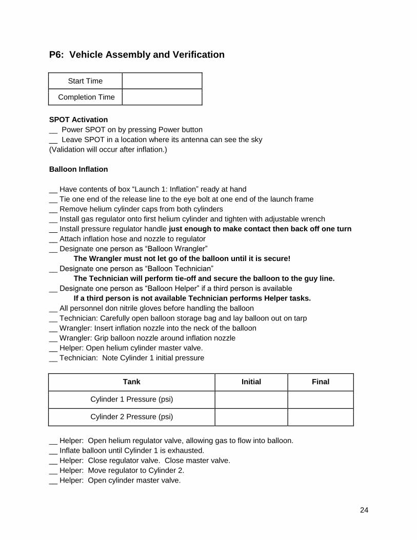
P6: Vehicle Assembly and Verification
Start Time
Completion Time
SPOT Activation
__ Power SPOT on by pressing Power button
__ Leave SPOT in a location where its antenna can see the sky
(Validation will occur after inflation.)
Balloon Inflation
__ Have contents of box “Launch 1: Inflation” ready at hand
__ Tie one end of the release line to the eye bolt at one end of the launch frame
__ Remove helium cylinder caps from both cylinders
__ Install gas regulator onto first helium cylinder and tighten with adjustable wrench
__ Install pressure regulator handle just enough to make contact then back off one turn
__ Attach inflation hose and nozzle to regulator
__ Designate one person as “Balloon Wrangler”
The Wrangler must not let go of the balloon until it is secure!
__ Designate one person as “Balloon Technician”
The Technician will perform tie-off and secure the balloon to the guy line.
__ Designate one person as “Balloon Helper” if a third person is available
If a third person is not available Technician performs Helper tasks.
__ All personnel don nitrile gloves before handling the balloon
__ Technician: Carefully open balloon storage bag and lay balloon out on tarp
__ Wrangler: Insert inflation nozzle into the neck of the balloon
__ Wrangler: Grip balloon nozzle around inflation nozzle
__ Helper: Open helium cylinder master valve.
__ Technician: Note Cylinder 1 initial pressure
Tank Initial Final
Cylinder 1 Pressure (psi)
Cylinder 2 Pressure (psi)
__ Helper: Open helium regulator valve, allowing gas to flow into balloon.
__ Inflate balloon until Cylinder 1 is exhausted.
__ Helper: Close regulator valve. Close master valve.
__ Helper: Move regulator to Cylinder 2.
__ Helper: Open cylinder master valve.

25
__ Technician: Note Cylinder 2 initial pressure
__ Helper: Open regulator valve, allowing gas to flow into balloon.
__ Inflate balloon until Cylinder 2 is exhausted (or tare weight lifted or nozzle lift achieved).
__ Helper: Close regulator valve. Close master valve.
__ Technician: Note Cylinder 2 final pressure.
__ Wrangler: Hold balloon neck closed at very top of neck. Use two hands.
__ Technician: Fold balloon neck lengthwise twice, insert through top loop of flight harness, fold
back, and tie off with three tie-off strings. (Helper can assist with bringing up flight harness,
handing tools, etc.) See figure.
__ Technician: Tie release line
loop through suspension loop.
__ Technician: Thread release
line through release line loop and
tie to opposite end of launch
frame.
__ When Technician is satisfied
that the balloon is secure, the
Wrangler may carefully release
the balloon.
__ Adjust release line to suspend
the spreader bar just above
shoulder height.
The following steps may require
adjustment of the release line
length in order to make the
balloon height convenient for each
step
__ Cap both gas cylinders.
__ Stow all tools and extraneous
equipment.
Flight Train Layout
__ Verify SPOT is operational by
checking the findmespot.com website. Account ALTAIR; Password ALTAIR5.
__ Install SPOT in pocket on inside of gondola hat. Make the white tape visible in pocket
(antenna points to sky). Tape in place with orange duct tape.
__ Adjust the spreader bar to its nominal position.
__ Pass cutdown string through one suspension loop, knot on short side of cutdown string just
outside loop.
__ Attach one end of parafoil support string to same side of spreader bar as cutdown string,
__ Unpack parafoil and accordion fold carefully. Once clips are free, do not let them go.

26
__ Pass free ends of cutdown string and support string through parafoil shrouds just behind
second row of shrouds.
__ Attach support string to support parafoil.
__ Pass cutdown string through second suspension loop.
Parafoil should now be suspended securely with both cutdown strings hanging down.
__ Install RF beacon antenna on gondola.
__ Install telemetry antenna on gondola.
__ Slide hat over RF beacon antenna.
__ Use threading tool to thread steering strings through holes in hat, and clip to parafoil clips.
Be sure to get the Right steering string to the Right clip!
__ Remove tape from gondola main power switch
__ Set gondola power switch to ON.
__ Use threading tool to thread cutdown strings through holes in hat.
Twist each cutdown string 10 times before feeding.
__ Feed cutdown strings through eyelets and pass on end through the other as shown in the
figure.
__ Execute cutdown on computer to set string
__ While plunger retracts, thread loop down so rigging is as in diagram below (hat not shown for
clarity).
__ Set gondola main power switch to OFF.

27
__ Raise balloon to suspend gondola just off the ground. Adjust the cutdown strings so the loop
over the plunger is just snug and the gondola sits level.
__ Settle hat snugly on top of gondola. (It can’t go down too far.)
__ Carefully arrange parafoil in the “fanfold” arrangement shown in the figure. There will be 4
pleats each side of center. Keep the fold over the cutdown string (and support line)
approximately centered between the rows of shroud lines.
__ Remove parafoil suspension line. Cut it free if necessary.
__ Verify cutdown stirings pass between forward and aft portions of the parafoil.
__ Verify all shroud lines hang free.
__ Verify all front vents are open (and face forward!)
__ Cover parafoil with space blanket.
Camera Setup
Camera materials and tools are located in Box Launch 5: MISC Bag 1
__ Screw the mount to the gondola foam cap at the marked location
__ Set mode switch on left of camera to VIDEO
__ Verify camera SD card is installed and seated

28
__ Slide the camera pocket clip over the camera mount with lens (not the white button!) facing
forward. The lens is on the same side as the clip.
__ Tape camera to the camera mount with vinyl tape. Place the tape low to keep tape clear of
controls on camera.
Payload Life Check
__ Point telemetry antenna down and tighten connector.
__ Verify ground station GO for life test
__ Remove on/off foam plug from the hat (don’t lose it)
__ Set gondola main power switch ON
__ Verify data received at ground station
__ Verify Beacon operational
__ Verify Lights operational
__ Verify Mux operational
__ Verify GPS operational
__ SET GONDOLA MAIN POWER SWITCH OFF
__ Replace the foam on/off switch plug (match orientation marks)
__ Dry gondola with paper towels if necessary
__ Remove diffuser cover
__ Advise Flight Director of status
P7: Launch
__ Verify Vehicle Go for Launch
__ Verify Launch Ground Station Go for Launch
__ Verify Science Go for Launch
__ Verify Recovery Go for Launch
__ Remove space blankets from vehicle
__ VERIFY TELEMETRY ANTENNA TIGHT AND ORIENTED TO POINT DOWN
__ Remove foam on/off switch plug
__ SET GONDOLA MASTER POWER SWITCH ON
__ Replace foam on/off switch plug; tape down (match orientation marks)
__ Verify parafoil ready
__ Verify Launch ground station receiving data
__ Verify Tracker XLS and KML logging check boxes checked
__ Check Track box
__ Activate Video Camera
__ Slide power switch on right side of video camera from OFF to ON
__ Press and hold the large white button until the green light comes on
__ Verify Blue light (on the right) comes on, indicating camera is in video mode
__ Press big white button on camera to start recording
__ Command Optical Beacon to Flash

29
__ Verify optical beacon is flashing
__ Verify payload telemetry
__ GPS fix
__ All Temperatures 15-30°C
__ (Orientation within 5° horizontal)
__ Avionics and Lights battery voltages > 7.5 V
__ START TRACKER LOG
__ Complete the following steps as near to simultaneously as possible
__ Release guy line to launch vehicle
__ Click “RELEASE” Button in tracker software to begin mission timer
Release Time (hh:mm:ss, UTC):
__ Inform Science of Release Time
__ Inform Recovery of Release Time
__ Science enter Release Time
__ Recovery enter Release Time
Immediately continue to P8 on next page

30
P8: Flight
- Continually slew the ground station antenna to maintain the azimuth indicated by the Tracker
- Monitor flight parameters
- Remain in contact with Science
Event: Acquisition of Signal (AOS)
All Sites--
__ Advise Flight Director of LOS
Event: Altitude: 1 km
Climb Rate (m/s):
Start science protocol.
Event: Altitude: 3 km
__ Arm cutdown system
Event: Altitude (4 km), Cutdown
__ Execute cutdown as vehicle passes planned cutdown altitude
Cutdown Altitude (km)
Cutdown Time (hh:mm:ss, UTC)
Initial Descent Rate (m/s)
Event: Loss of Signal (LOS)
All Sites--
__ Advise Flight Director of LOS
__ Log last GPS fix and rates
__ Make screenshot of last screen
Lat (dd.dddd)
Lon (dd.dddd)
Alt (m)
ROC (m/s)
GSP (m/s)
CRS (dd)

31

32
P9: Post Flight Documentation
__ COPY ALL FLIGHT FILES TO THUMB DRIVE
__ Enter all observed values into the flight properties table
__ Note any equipment used from box of spares or from sources not in procedures
__ Pack equipment in boxes
P10: Recovery
Assembly of recovery ground station is discussed in P5(R).
- Estimate time required to recover payload given LOS location and expected terrain
- Travel to last GPS fix
- Listen for RF Beacon
- Record position data
- Proceed to location of vehicle

33
Part 3: Reference
Site Data
Site Lat Lon Elevation
Whitefield (KHIE) +44.3675556° -71.5458056° 1072 ft, 327 m
Rutland +43.5299167° -72.9496389° 787 ft, 240 m
Garipay +43.717540° -72.272527° 523 ft, 160 m
Springfield (KVSF) +43.3437222 -72.5172778° 578 ft, 176 m
Taftsville +43.619248° -72.457326° 550 ft, 168 m
Thetford +43.815978° -72.232200° 974 ft, 297 m
Mt. Cardigan +43.649448° -71.914267° 3156 ft, 962 m
Robert Frost Ln. +43.685450° -72.199085° 1375 ft, 419 m
Barnes (Norwich) +43.7209° -72.3325° 951 ft, 290 m
Frequency List
Telemetry 900-912 MHz Net ID = 07
SPOT Tracking data: findmespot.com Account: ALTAIR PW: ALTAIR5
Team Communications Moose Mountain Repeater
Repeater Frequency Offset PLL Tone?
Moose Mountain 145.330 MHz -600 kHz 100 Hz

34
Emergency Phone Numbers
FAA: (800) 992-7433 Burlington FSS
Boston Center area B: (603) 879-6665 Air traffic control
Vermont State Police: (802) 878-7111 State Recreational Enforcement
New Hampshire State Police: (603) 271-2450 Director’s Office, Concord NH
Personnel and Contact Information
Personnel Position Site Contact
Yorke Brown Principal Investigator Science 603-727-8494 AC4E
Justin Albert Principal Investigator Launch 250-661-7066
Bob Eccher Launch Technician Launch 802-281-9456
Galen Brown Flight Director Launch
Asher Lantz Science Technician Science

35
T-30 Hour Predictions
T-12 Hour Predictions

36
T-6 Hour Predictions (Failed Cutdown)

37
Vehicle Flight Properties (from A12)
Climb Rate 5.8 m/s
Descent Rate 3.1 m/s
Airspeed 8.1 m/s
Turn Rate 8 deg/s