alre – innovation with competence and traditioncontrols-uk.com/alre_tech/alre_flyer_thermostats...
TRANSCRIPT

alre – innovation with competence and tradition
Thermostats for Control Cabinets
Thermostats for Control Cabinetsto protect electric and electronic
components from heat, cold, and
humidity inside the control or
distributor cabinets and
automated systems.
Inte
llig
ent
solu
tions
for
all a
reas
to
be
con
tro
lled

Thermostats for Control Cabinets | Page 2
Thermostats for Control Cabinets RTBSSThermostat with bimetallic sensor
Technical specifi cations Application
Operating voltage: 24 ... 250V~ / 24 … 48V (changer only) Used to monitor the temperature in switch cabinets, automated system, enclosures
Sensor: bimetalSwitching capacity: N/C contact/ N/O contact 24V~ 250V~/10(2)A,
24V … 48V max. 30Wchanger contact cooling: 24V~ 250V~/10(2)A,24V ... 48V — max. 30W changer contact heating: 24V~ 250V~/10(2)A,24V - ... 48V - max. 30W
Contact: 1 N/O contact (heating), 1 N/C contact (cooling) or 1 changer contact (heating/cooling)
Switching differential: see TableEquipment: Outside setting, twist-type knob Protection type: IP30Protection class: 0 (protection class must be ensured by the
installation site)Type of connection: Screw terminals 0.5 ... 2.5mm2
Type of installation: on DIN-bar (35mm)Ambient air temperature: -20T40 (-20 ... 40°C)
0T60 (0 ... 60°C)Enclosure: Plastic, gray (RAL7035) Weight: approx. 50gCertifi cations: UL, VDE (only 0...60°C types)
Type Product No. Setting range Switching differential Equipment Scale WG
RTBSS-110.250/04 ZN111524 0 … 60 °C 4 … 7K N/C contact (heating) red IIRTBSS-111.250/05 ZN112525 0 … 60 °C 4 … 7K N/O contact (cooling) blue IIRTBSS-112.250/07 ZN113527 0 … 60 °C 4 … 7K Changer (heating and cooling) gray IIRTBSS-111.130 ZA112310 -20 … 40 °C <3K N/O contact (cooling) blue IIRTBSS-112.130 ZA113310 -20 … 40 °C <3K Changer (heating and cooling) gray IIRTBSS-112.230 ZA113320 0 … 60 °C <3K Changer (heating and cooling) gray IIRTBSS-112.111 ZA113110 -20 … 40 °C ~1K* Changer (heating and cooling) gray IIRTBSS-112.211/12 ZN113152 0 … 60 °C ~1K* Changer (heating and cooling) gray II
* with thermal return, only with an operating voltage of 230V~
Type Equipment WG
JZ-13 ZA990001 Standard track with drill holes to fasten thermostats for control cabinets (length 40mm) II
For circuit diagrams, dimensional drawings see page 7
RTBSS 110.xxx (N/C contact) RTBSS 111.xxx (N/O contact) RTBSS 112.xxx (changer contact)
RF only with RTBSS-112x11

Thermostats for Control Cabinets | Page 3
Ind
ustr
ial t
echn
olo
gy
Thermostats for Control Cabinets RTKSS, PTR Thermostats with capillary sensors
Technical specifi cations ApplicationSensor: Capillary (1.5m) Temperature control to monitor
the temperature in control cabinets, automated systems, enclosures
Switching capacity: Changer heating: 24V~…250V~/10(2)A,24V … 48V max. 30WChanger cooling: 24V~ … 250V~/5(2)A, 24V … 48V max. 30W
Contact: Changer (heating/cooling)Switching differential: <7KEquipment: Outside setting, twist-type knobProtection type: IP30Protection class: 0 (protection class must be ensured by
the installation site)
Type of connection: Screw terminals 0,5 ... 2,5mm2
Type of installation: on DIN-bar (35mm)Ambient air temperature: min. -20°C … max. control temperature
plus 15% (see setting range), approx. 50gEnclosure: Plastic, gray (RAL7035) Weight: approx. 70g
Type Product No. Setting range Switching differential Equipment Scale WG
RTKSS-112.270/07 ZN143727 0 … 60 °C <7K 1 changer (heating/cooling) gray IIRTKSS-112.370 ZA143730 20 … 80 °C <7K 1 changer (heating/cooling) gray II
Thermostat with bimetallic sensor, design PikoloTechnical specifi cations ApplicationOperating voltage: 230V~ Temperature control to
monitor the temperature in control cabinets, automated systems, enclosures
Sensor: BimetallicSwitching capacity: Heating: 10(4)A, Cooling: 5(2)AContact: 1 changer Switching differential: approx. 2KEquipment: Outside setting, range specifi cations
under the knobProtection type: IP30Protection class: II, after the appropriate installationType of connection: Screw terminals 0,5 ... 2,5mm2
Type of installation: on DIN-bar (35mm)
Ambient air temperature: min. -20°C … max. control temperature plus 15%
Enclosure: Plastic, gray (RAL7035) Weight: approx. 85g
Type Product No. Setting range Switching differential Equipment Scale WG
PTR 01.082 A201302 10 … 60°C approx. 2K 1 changer (heating/cooling) black II
Accessories WG
JZ-13 ZA990001 Standard track with drill holes to fasten thermostats for control cabinets (length 40mm) IIJZ-15 ZA990002 Installation set to fasten the remote capillary sensor II
For circuit diagrams, dimensional drawings see page 7
RTKSS 112.xxx (changer) PTR 01.082

Thermostats for Control Cabinets | Page 4
Peltier thermostats CTRRS, KTRRN Heating or cooling
Technical specifi cations ApplicationOperating voltage: 24V , ±15% Peltier thermostat to connect a
Peltier element to heat or cool – to climatize switch cabinets, ticket machines and ATM or similar applications.
Sensor: Internal NTCSwitching capacity: 14A (max. 16A/60,000 operating cycles)Contact: Changer (cooling = N/C contact,
heating = N/O contactPower consumption: 0,75WSetting range: 0 … 60°CSwitching differential: approx. 2 …3KEquipment: Outside setting, twist-type knobProtection type: IP30Protection class: IIIType of connection: Screw terminals 0,5 ... 2,5mm2
Type of installation: on DIN-bar (35mm)Ambient air temperature: -10T60 (-10 … 60°C)Enclosure: Polyamide PA6.6 (UL94 V-0),
gray (RAL7035)Knob colour/scale: grayWeight: approx. 70g
Type ProductNo. Equipment WG
CTRRS-161.000/04 DN600004 Peltier thermostat for heating and cooling II
Heating and CoolingTechnical specifi cations ApplicationOperating voltage: 24V Peltier thermostat to connect a
Peltier element to heat or cool – to climatize switch cabinets, ticket machines and ATM or similar applications.
Sensor: Internal or optionally external 2k sensorSwitching capacity: Peltier element: 16A; fan output: 2(1)AContact: 2 x N/O contacts (heating and cooling)
with neutral zone; (Peltier element); N/O contact (fan)
Power consumption: Approx. 1WSetting range: Heating: 0 … 20°C; cooling: 0 … 50°CSwitching differential: Approx. 1KEquipment: Separate control areas for heating and
cooling; neutral zone of at least 10K. The fan is only activated during heating and cooling.
Protection type: IP20Protection class: IIIType of connection: Screw terminals 0,5 ... 2,5mm2
Type of installation: on DIN-bar (35mm)Ambient air temperature: -10T55 (-10…55°C)Enclosure: Plastic ABS, gray (RAL7035) Knob colour/scale: grayWeight: approx. 105g
Type ProductNo. Equipment Ext. sensor (optional) WG
KTRRN-267.014/03 DN460003 Peltier thermostat for heating and cooling, fan control “8“ (NTC 2K), page 8 II
Accessories WG
JZ-13 ZA990001 Standard track with drill holes to fasten thermostats for control cabinets (length 40mm) II
For circuit diagrams, dimensional drawings see page 7
CTRRSCooling
KTRRNCTRRSHeating
If the temperature drops below the set heating switch point, the thermostat turns on the outside fan and activates the Peltier ele-ment, whereby the direction of the direct current effects the heating of the control cabinet. If the set cooling switch point is exceeded, the outside fan is turned on and the Peltier element is activated by the opposite direction of the direct current. The opposite direction of the direct current effects the cooling of the control cabinet.
Function
Controller
Peltier element
Controller
Peltier element
Supply voltage
Peltier element
Fan
Remove bridge, if connected to an external tempera-ture sensor.
External temperature sensor

Thermostats for Control Cabinets | Page 5
Ind
ustr
ial t
echn
olo
gy
Control cabinet hygrostats RFHSS, PHY
Technical specifi cations ApplicationSensor: Plastic fi bers Hygrostat to monitor and control
the humidity in switch cabinets, beverage or cigarette machines
Switching capacity: RFHSS-112.110/02
RFHSS-113.110/01
Humidify: 24V~…250V~/2(0.2)A at 24V~ min. 100mADehumidify: 24V~…250V~/5(0.2)A at 24V~ max. 100mA, 48V~/ min.: 5 mA, 5V~/
Contact: 1 changerSwitching differential: ~5% rel. humidityEquipment: Outside adjustment, twist-type knobProtection type: IP30Protection class: 0 (protection class must be ensured at
the installation site)Type of connection: Screw terminals 0,5 ... 2,5mm2
Type of installation: on DIN-bar (35mm)Ambient air temperature: T60 (0 ... 60°C)Enclosure: Plastic, gray (RAL7035) Knob colour/scale: blueWeight: approx. 50gApprovals: UL (only RFHSS-112 and only 230V)
Type Product No. Setting range Equipment WG
RFHSS-112.110/02 ZN273002 40 … 90% rel.humidity 1 changer IIRFHSS-113.110/01 ZN274001 40 … 90% rel.humidity 1 changer, gold contacts II
Design PikoloTechnical specifi cations ApplicationSensor: Plastic fi bers Hygrostat to monitor and control
the humidity in switch cabinets, beverage or cigarette machines
Switching capacity: Dehumidify: 5(0,2)A; Humidifying: 2(0,2)A at 24V~ min. 100mAMin.: 100mA, 24V~
Contact: 1 changerSwitching differential: ~4% rel. humidityEquipment: Outside adjustment, range specifi cation
beneath knobProtection type: IP30Protection class: II upon appropriate installationType of connection: Screw terminals 0,5 ... 2,5mm2
Type of installation: on DIN-bar (35mm)Ambient air temperature: 10 ... 60°CEnclosure: Plastic, gray (RAL7035) Knob colour/scale: blueWeight: approx. 85g
Type Product No. Setting range Equipment Skala WG
PHY 60.082 A261004 30 ... 100% rel.humidity 1 changer gray II
Accessories WG
JZ-13 ZA990001 Standard track with drill holes to fasten thermostats for control cabinets (length 40 mm) II
For circuit diagrams, dimensional drawings see page 7
PHY 60.082RFHSS-11x.110
2 = HUMIDIFYING
4 = DEHUMIDIFYING
Thermostats for Control Cabinets | Page 6
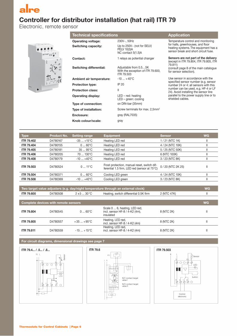
Controller for distributor installation (hat rail) ITR 79 Electronic, remote sensor
Technical specifi cations ApplicationOperating voltage: 230V~, 50Hz Temperature control and monitoring
for halls, greenhouses, and fl oor heating systems. The equipment has a sensor break and short circuit fuse.
Sensors are not part of the delivery (except in ITR 79.804, ITR 79.805, ITR 79.811)(consult page 8 of the main catalogue for sensor selection).
Use sensor in accordance with the specifi ed sensor number (e.g. sensor number 24 or 4: all sensors with this number can be used, e.g. HF-4 or LF 24). Avoid installing the sensor line parallel to the power supply line or to shielded cables.
Switching capacity: Up to 250V~ (not for SELV)PELV 10(3)ANC contact 5(1.5)A
Contact: 1 relays as potential changer
Switching differential: Adjustable from 0.5…5KWith the exception of ITR 79.600,ITR 79.503
Ambient air temperature: -10 ... + 40°C
Protection type: IP 20
Protection class: II
Operating display: LED – red: heatingLED – green: cooling
Type of connection: on DIN-bar (35mm)
Type of installation: Screw terminals for max. 2,5mm2
Enclosure: gray (RAL7035)
Knob colour/scale: gray
Type Product No. Setting range Equipment Sensor WG
ITR 79.402 D4780167 -35 ... +15°C Heating LED red 1 / 21 (NTC 1K) IIITR 79.404 D4780155 0 ... 60°C Heating LED red 4 / 24 (NTC 10K) IIITR 79.405 D4780181 35 ... 95°C Heating LED red 5 / 25 (NTC 50K) IIITR 79.406 D4780205 70 ... 130°C Heating LED red 6 (NTC 100K) IIITR 79.408 D4780179 -10 ... +40°C Heating LED red 3 / 23 (NTC 8K) II
ITR 79.503 D4780524 0 ... 11°C Frost protection, manual reset, switch dif-ferential 1.5 fi rm, LED red (sensor at 75°C) 0 / 20 (NTC 2K 25) II
ITR 79.504 D4780371 0 ... 60°C Cooling LED green 4 / 24 (NTC 10K) IIITR 79.508 D4780369 -10 ... +40°C Cooling LED green 3 / 23 (NTC 8K) II
Two target value adjusters (e.g. day/night temperature through an external clock) WG
ITR 79.600 D4780508 2 x 5 ... 30 °C Heating, switch differential 0.5K fi rm 2 (NTC 47K) II
Complete devices with remote sensors WG
ITR 79.804 D4780545 0 ... 60°CScale 0 ... 6, heating, LED red, incl. sensor HF-8 / 4-K2 (4m), insulated
8 (NTC 2K) II
ITR 79.805 D4780557 + 35 ... + 95°C Heating, LED red,incl. sensor HF-8 / 4-K2 (4m) 8 (NTC 2K) II
ITR 79.811 D4780559 - 15 ... + 15°CHeating, LED red,incl. sensor HF-8 / 4-K2 (4m) 8 (NTC 2K) II
For circuit diagrams, dimensional drawings see page 7
ITR 79.4... / .5... / .8... ITR 79.503ITR 79.6
N/C contact target value I
N/O contact target value II
Control electronic
Sen
sor
Sensor
LED
button
Thermostats for Control Cabinets | Page 7
Ind
ustr
ial t
echn
olo
gy
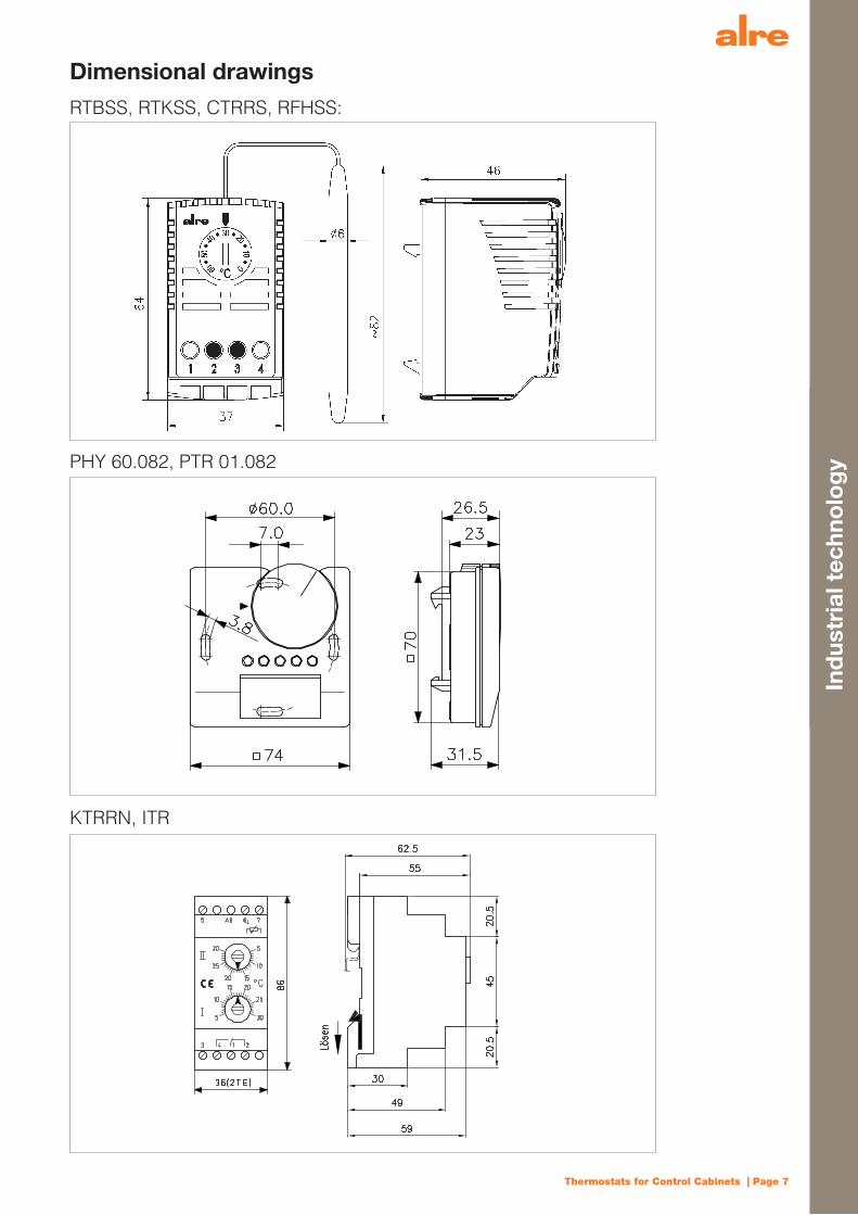
Dimensional drawings
RTBSS, RTKSS, CTRRS, RFHSS:
PHY 60.082, PTR 01.082
KTRRN, ITR

Thermostats for Control Cabinets | Page 8
Sen
sor
tech
nolo
gy
Sleeve temperature sensors HF(Remote sensors for Alre standard equipment, e.g. ITR79…)
Technical specifi cations
Ambient air temperature with PE cable: –50 ... +85°CAmbient air temperature with silicon cable:
–50 ... +150°C
Ambient air temperature with PVC cable: –5 ... +70°CProtection type: IP 65Sensor line (can be extended up to): NTC 50m,
PTC 100mSensor characteristics: See main catalogue
(Please follow the EMV guidelines. Avoid installing lines parallel to power supply lines or shielded lines.)In V2 A sleeve molded (except … K = plastic sleeve). Time constant of approx. 20sec in moving water.
Type Product No. Sensor
HF-0 D4779114 “0” (NTC 2K 25) PE cable 1.5mHF-0/6 D4779126 “0” (NTC 2K 25) PE cable 6mHF-1 D4779203 “1” (NTC 1K) PE cable 1.5mHF-2 D4779823 “2” (NTC 47K) PE cable 1.5mHF-3 D4779090 “3” (NTC 8K) PE cable 1.5mHF-3/6 D4779102 “3” (NTC 8K) PE cable 6mHF-4 D4779088 “4” (NTC 10K) PE cable 1.5mHF-4/6 D4779710 “4” (NTC 10K) PE cable 6mHF-5 D4779025 “5” (NTC 50K) PE cable 1.5mHF-5/4K2 D4771303 “5” (NTC 50K) PVC cable (HAR) 4mHF-5/4K3* D4771304 “5” (NTC 50K) Silicon cable 4mHF-5/6 D4779619 “5” (NTC 50K) PE-Kabel 6mHF-6 D4779037 “6” (NTC 100K) Silicon cable 1.5mHF-6/3 D4779835 “6” (NTC 100K) Silicon cable 3mHF-8/4K2 G8000370 “8” (NTC 2K) PVC cable (VDE) 4m acc. to DIN 44574HF-8/6K2 G8000368 “8” (NTC 2K) PVC cable (VDE) 6m acc. to DIN 44574
* Please note: for diameters larger than 8.9mm for TH/NTH 140 see main catalogue
Application
To measure the temperature of liquid media by installing sleeve temperature sensors (TH/NTH). To measure the temperature of air and non-aggressive gases in the air duct by installing a spring guard.
Dimensional drawings
HF HF-5/4K3HF-8/...K2
HF-5/4K2
plastic plastic
plastic

Att
ache
men
t
* Bec
ause
of t
he th
erm
al re
turn
the
RTB
SS 1
12.x
11 w
ith 1
K sw
itchi
ng d
iffer
entia
l nee
ds a
sup
ply
volta
ge o
f 230
V~
Ove
rvie
w o
f th
e C
ont
rol C
abin
et T
herm
ost
ats
Ther
mos
tats
H
umid
ity c
ontr
olle
rPe
ltier
ther
mos
tat
Bui
lt-in
th
erm
osta
t
RTB
SS11
0.x5
0RT
BSS
111.
x50
RTB
SS11
2.x5
0RT
BSS
111.
x30
RTB
SS11
2.x3
0RT
BSS
112.
x11
RTKS
S11
2.x7
0PT
R
01.0
82R
FHSS
112.
110
PHY
60.0
82C
TRR
SKT
RR
NIT
R 7
9
Con
tact
N/C
con
tact
N/O
con
tact
sC
hang
erN
/O c
onta
cts
Cha
nger
Cha
nger
Cha
nger
Cha
nger
Cha
nger
(coo
ling=
N/C
co
ntac
t; he
atin
g =
N/O
con
tact
)
2x N
/O c
onta
ct (h
ea-
ting
and
cool
ing)
with
ne
utra
l zon
e (P
eltie
r el
emen
t); N
/O
cont
act (
vent
ilatin
g)
Cha
nger
Volta
ge*
24V~
… 2
50V~
/24V
…
48V
m
ax. 3
0W
24V~
... 2
30V~
24V
Up
to 2
50V
(not
for S
ELV)
Cur
rent
10(2
)A10
(2)A
N/C
con
tact
10
(2) A
N/O
co
ntac
t 5(2
)A10
(2)A
N/C
con
tact
10
(2) A
N/O
co
ntac
t 5(2
)A
N/C
con
tact
10
(2) A
N/O
co
ntac
t 5(2
)A
N/C
con
tact
10
(2) A
N/O
co
ntac
t 5(2
)A
N/C
con
tact
10
(4) A
N/O
co
ntac
t 5(2
)A
Deh
umid
ify a
t 5(0
,2)A
Hum
idify
at 2
(0,2
)AM
inim
um 1
00 m
A (a
t 24V
~)
14A
(max
. 16A
/60,
000
oper
atin
g cy
cles
)
2-po
le s
witc
h co
ntac
t for
one
Pelti
er e
lem
ent 1
6AVe
ntila
tor o
utpu
t 2(1
)A
PELV
10(
3)A
NC
con
tact
:5
(1.5
)A
Con
trol r
ange
sx=
1: -2
0 ...
40°
C
x=2:
0
... 6
0°C
x=
3: -2
0 ...
80°
C
10 ..
. 60°
C40
... 9
0%
rel.
hum
idity
30 ..
. 100
%
rel.
hum
idity
0 …
60°
CH
eatin
g: 0
…20
°CC
oolin
g: 3
0…50
°C
-35…
130°
CD
epen
ding
on
the
type
Switc
hing
diff
eren
tial*
4 ..
. 7K
ca.
3K
ca.
1K
< 7
K2K
ca.
5%
rel.
hum
idity
ca.
4%
rel.
hum
idity
2 …
3K
ca. 1
K0.
5…5K
adj
usta
ble
(exc
ept I
TR 7
9.60
0)
Sens
or e
lem
ent
Bim
etal
lic s
enso
rC
apilla
ry
(1.5
m)
Bim
etal
licPl
astic
fibe
rsIn
tern
al 4
7k s
enso
rIn
tern
al o
r ext
erna
l 2k
sen
sor
NTC
Type
of c
onne
ctio
nSc
rew
term
inal
s 2,
5mm
2
Ambi
ent a
ir te
mpe
ratu
re
(sto
rage
tem
pera
ture
)
x=1:
-20
... 4
0°C
x=2:
0
... 6
0°C
(-20
...+8
0°C
)
Min
.-20°
CM
ax. c
ontro
l te
mp.
+15
%
10 ..
. 60°
C(-2
0 ...
70°
C)
0 ...
60°
C(-2
0 ...
80°
C)
10 ..
. 60°
C(-2
0 ...
60°
C)
-10
... 7
0°C
(-20
... 7
0°C
) -1
0 …
55°
C(-2
0 ...
70°
C)
-10
... +
40°C
(-20
... 6
0°C
)
Prot
ectio
n ty
peIP
30IP
20
Prot
ectio
n cl
ass
0 (th
e pr
otec
tion
clas
s m
ust b
e en
sure
d on
-site
)(P
TR a
nd P
HY
are
prot
ectio
n cl
ass
II)III
II
Knob
col
orre
dbl
uegr
aybl
uegr
aygr
aygr
aygr
aybl
uegr
aygr
ay
Encl
osur
eKu
nsts
toff
Appr
ox. w
eigh
t50
g70
g85
g50
g85
g70
g10
5g
100V
...
230V
~

Thermostats for Control Cabinets | Page 10
Technical TermsBimetal
In general, thermo-bimetal is composed of about two equal layers of metals or alloys, which are firmly connected with one another; however, they expand to a different degree upon exposure to heat. There it flexes when the temperature changes. If the heat rises, one side distends while the other metallic component does not expand as much. The heat is transferred from the environment through the conductivity, radiation or convection (indirect heating).
Capillary sensor:
Capillary sensors use the thermal expansion of a liquid to measure temperature. Liquid with a defined expansion coefficient is filled in a metallic pipe (papilla). The liquid is transported through the capillary to a membrane, which transforms the thermal expansion into a mechanical movement. This motion can then be used to activate a micro-switch. Capillary sensors are often used in immersion sleeves or in contact sensors. They work free of any ancillary energy.
Neutral zone:
Any control range, which does not heat or cool is defined as neutral zone.
N/C contact (bimetallic):
This control contact opens as the temperature rises and closes as the temperature drops (for “heating”).
Peltier element:
A Peltier element is an electrical component that generates a temperature difference between two pole plates when under direct voltage. The physical basis for it is the Peltier effect (according to Jean Peltier (1785-1845)). When the polarity of the voltage fluctuates, the heat and cold pole switch. There-fore, Peltier elements can be used in small enclosures and devices for both heating and cooling. To increase the effectiveness and thermal output, the elements are generally cascaded. The advantage of this application is that they can cool without requiring a coolant and they can heat at the same time. Peltier thermostats are maintenance-free.
Switch differential and hysteresis:
This is the difference between turning the heat or thermostat on and off.The specified switch differential refers always to the thermostat. It does not specify the truly generated hysteresis of the room temperature.It changes depending on the location where it is used and the conditions under which it is used. The room temperature is always subject to fluctuations. These fluctuations result in the switch differential of the thermostat, the room’s characteristics such as the heating time, loss of heat, etc. and the levels of disturbance.”
N/O contact (bimetallic):
This control contact closes when the temperature rises and opens when the temperature drops (for “cooling”).
Thermal return:
The additionally installed heating resistor ensures that the thermostat is turned off in time during the heating process. Therefore, it reduces an overshoot of room temperature and it generates a smaller switching differential.
Changer (bimetallic):
This is a changer with an N/C and N/O contact. It works as described under N/C and N/O contact.
General Delivery Terms and ConditionsWe deliver exworks in accordance with the known “General Delivery Terms and Conditions for Products and Services of the Electro- and Electronic Indus-try” as of June 2005 plus the “Supplemental Clause: Expanded Retention of Title”, which we are happy to provide upon request. These “General Delivery Terms and Conditions for Products and Services of the Electro- and Electronic Industry” apply together with the following Sales and Delivery Terms and Conditions; however, under the provisio that if there is any contradictory content between the “General Delivery Terms and Conditions for Products and Services of the Electro- and Electronic Industry” and our Sales and Delivery Terms and Conditions, the latter shall apply. These “General Delivery Terms and Conditions for Products and Services of the Electro- and Electronic Industry” and our Sales and Delivery Terms and Conditions become effective upon order confirmation and replace any purchasing terms and conditions of the Customer even if we the order acceptance should be also an acknow-ledgment of these purchasing terms and conditions. By accepting our order confirmation without objections, the Customer acknowledges that he waives any legal objection on the basis of his purchasing terms and condition; we hereby accept this waiver. Our Terms and Conditions shall also apply to all future business relationships even if they have not been expressly agreed. No later than at the time of delivery acceptance or the Customer’s acceptance of our service, these Terms and Conditions are deemed as re-accepted. We hereby object to the Customer’s order with reference to his purchasing terms and conditions. Any deviations from our terms and conditions are only effective, if we agreed to them in writing.
Safety RegulationsWhen dealing with products, it is imperative to comply with the applicable EU guidelines and to follow the installation and mounting instructions of the operating instructions. It is prohibited to copy this documentation or excerpts thereof without the consent of ALRE-IT Regeltechnik GmbH, Berlin. Jurisdiction is with the com-petent courts in Berlin.
Information about Technical DataThe technical data specified by us, was determined by us under laboratory conditions in accordance with the applicable standards. We only assure characteristics to this extent. All listed devices and components may only be used in accordance with their intended purpose. The Principal is responsible to check, whether the device is suitable for his intended purpose or use in compliance with the conditions of use. We will not assume any liabilities with regard to this matter. We reserve ourselves the right to make changes in products or documentations in accordance with technical advancement and the continuous improvement and therefore, products may differ from catalogue descriptions. Rights to misprints are reserved.
For additional products, consult our main catalogue or go to www.alre.de.
Att
ache
men
t
Thermostats for Control Cabinets | Page 11
Contact persons
Headquarters Southeast AreaALRE-IT Regeltechnik GmbH Postal code areas Sales Partner NorwayRichard-Tauber-Damm 10, D-12277 Berlin 01, 04-09, 364, 9 Instell asTel.: +49 (0) 30 399 84-0 Paul Kaiser Gjerdrums vei 16Fax: +49 (0) 30 391 7005 Tel.: +49 (0) 911 587 43 78 0484 OsloE-Mail: [email protected] Fax: +49 (0) 911 587 43 88 Tel.: +47 (0) 22 02 14 50Internet: www.alre.de E-Mail: [email protected] Fax: +47 (0) 22 02 14 51
In-house Sales E-Mail: [email protected] Management Tel.: +49 (0) 30 399 84-123 Internet: www.instell.noKlaus Lorenz Fax: +49 (0) 30 391 7005Tel.: +49 (0) 30 399 84-216 E-Mail: [email protected]: +49 (0) 30 391 7005E-Mail: [email protected] Export Sales Partner PortugalOffice Frank Dörfler SensorControl LDA Tel.: +49 (0) 30 399 84-214 Tel.: +49 (0) 30 399 84-219 Est. Nacional 247, KM 66,2 - F Fax: +49 (0) 30 391 7005 Fax: +49 (0) 30 391 7005 2705-847 Terrugem SNT E-Mail: [email protected] E-Mail: [email protected] Tel.: +351 219 615 460
In-house Sales Fax: +351 218 647 210 North Area Tel.: +49 (0) 30 399 84-213 E-Mail: [email protected] Postal code areas Fax: +49 (0) 30 391 7005 Internet: www.sensorcontrol.pt 02, 03, 1, 2, 30, 31, 38, 39 E-Mail: [email protected]ünter Rock
Feldgeräte für die GebäudeautomationTel.: +49 (0) 33056 435 150Fax: +49 (0) 33056 435 151 Sales Partner Romania Sales Partner SwitzerlandE-Mail: [email protected] Beespeed Automatizari S.R.L. sensortec GmbHIn-house Sales DN 59 km 8 + 550 m left Bahnhofstrasse 87Tel.: +49 (0) 30 399 84-127 TM – Moravita road 3232 Ins Fax: +49 (0) 30 391 7005 Communa Giroc 307221 Tel.: +41 (0) 32 312 70 00E-Mail: [email protected] Sat Chisoda, Modul 3 – Incontro 07 Fax: +41 (0) 32 312 70 09
Tel. / Fax: +40 256 204402 E-Mail: [email protected] Area E-Mail: offi [email protected] Internet: www.sensortec.chPostal code areas Internet: www.beespeed.ro32-36, 361-363, 365-37, 4, 50-53, 57-61, 657-659Axel Pauly Sales Partner Great BritainTel.: +49 (0) 2206 86 83 22 Sales Partner Netherlands Suka Controls LimitedFax: +49 (0) 2206 86 92 31 betec controls BV Easton Business CentreE-Mail: [email protected] Radeweg 25a Felix RoadIn-house Sales 8171 MD Vaassen Bristol, BS5 0HETel.: +49 (0) 30 399 84-122 Tel.: +31 (0) 578 577 179 Tel.: +41 (0) 1179 415 396Fax: +49 (0) 30 391 7005 Fax: +31 (0) 578 577 982 E-Mail: [email protected]: [email protected] E-Mail: [email protected] Internet: www.sukacontrols.co.uk
Internet: www.beteccontrols.nl Contact person: Dagmar RaajSouthwest AreaPostal code areas54-56, 63, 64, 650-656, 66-69, 7
Sales Partner France Sales Partner Russian FederationDISIMPEX SA 2А-Автоматизация14, rue Joseph Graff Russian Federation67810 Holtzheim Moscow
In-house Sales
Tel.: +33 (0) 3 90 20 74 20 Volgogradskiy Prospekt
Tel.: +49 (0) 30 399 84-122
Fax:+33 (0) 3 88 76 90 83 Building 47, Offi ce 124
Fax: +49 (0) 30 391 7005
E-Mail: [email protected] Offi ce phone: +7 (495) 988-92-57
E-Mail: [email protected]
Internet: www.disimpex.fr E-mail: [email protected]: www.2ae.ru
South AreaPostal code areas
Sales Partner Austria ThermoTrade Engineering
8
eh-technik Russian Federation
Ludwig Fischer
Reinbacher GmbH & Co KG 190020 St. Petersburg
Tel.: +49 (0) 821 26 23 119
Gniglerstraße 54 Bumaznaya str. 3
Fax: +49 (0) 821 26 23 120
5020 Salzburg Tel.: +7 (812) 9562 448
E-Mail: [email protected]
Tel.: +43 (0) 662 87 00 53 +7 (921) 9562 448
In-house Sales
Fax: +43 (0) 662 87 00 53 20 Internet: www.tt-eng.ru
Tel.: +49 (0) 30 399 84-127
E-Mail: offi [email protected] Contact person: Julia Elisejeva
Fax: +49 (0) 30 391 7005
Internet: www.eh-technik.at
E-Mail: [email protected]

www.alre.de ALRE-IT Regeltechnik GmbHRichard-Tauber-Damm 10D-12277 Berlin
Tel.: +49 (0) 30 399 84-0Fax: +49 (0) 30 391 7005E-Mail: mail @ alre.de
DE
07/1
3/10
00