a.l.p.s. clavicle plating system - zimmerbiomet.com
TRANSCRIPT

A.L.P.S.® Clavicle Plating System
Surgical Technique
Table of Contents
Diverse Portfolio of Options .........................................................................................................2
Tailored Fit ..........................................................................................................................................4
Intuitive Instrumentation and Systematic Efficiency .........................................................5
Implant Options ................................................................................................................................6
Screw Options ...................................................................................................................................7
Key Instrument Features ...............................................................................................................8
Surgical Technique...........................................................................................................................9
Radiographic Assessment of the Fracture ...........................................................................9
Patient Positioning ...................................................................................................................10
Exposure ..................................................................................................................................... 11
Fracture Reduction .................................................................................................................. 14
Plate Selection ........................................................................................................................... 15
Plating Positioning ...................................................................................................................16
Plate Shortening Using F.A.S.T. GRIP Instruments .......................................................... 17
Plate Contouring Using Plating Benders ............................................................................ 17
Convex/Concave Bending .....................................................................................................18
Planar Bending ..........................................................................................................................18
Axial Bending.............................................................................................................................18
Plating Contouring Using F.A.S.T. GRIP Instruments ......................................................19
MIPO Approach with Anterior Plate ........................................................................................20
Drill Depth Limiting Instrumentation .................................................................................. 21
Screw Insertion .........................................................................................................................22
Standard Plate Using 3.5 mm Non-Locking Screws ................................................................22
Standard Plate Using 3.5 mm Locking or Multi-Directional Locking Screws ...........................23
Narrow Plate Using 2.7 mm Non-Locking Screws ...................................................................24
Narrow Plate using 2.7 mm Locking or Multi-Directional Locking Screws ...............................25
Closure ........................................................................................................................................26
Implant Removal .......................................................................................................................26

Disassembly Instructions ............................................................................................................27
Ordering Information ...................................................................................................................28
Implants ......................................................................................................................................28
Instruments and Disposables ................................................................................................ 31
Cases and Trays.........................................................................................................................32
Indications and Contraindications ...........................................................................................33
Note: Filling all the screw holes is not a requirement. Per this surgical technique, fixation may be achieved by having at least three screws on either side of the fracture

2 | A.L.P.S. Clavicle Plating System Surgical Technique
TAILORED FIT INTUITIVE INSTRUMENTATION SYSTEMATIC EFFICIENCYThe A.L.P.S. Clavicle Plating System expands the portfolio of shoulder fracture treatment options within the A.L.P.S. family of plating solutions. Zimmer Biomet offers a diverse portfolio of options for the continuum of care, from sports-related injuries to fracture fixation to joint replacement.
Diverse Portfolio of Options

3 | A.L.P.S. Clavicle Plating System Surgical Technique
Sports Medicine
• ZipTight™ Fixation System in AC
Extremities
• Comprehensive® Shoulder with Micro Stem
Trauma
• A.L.P.S. Clavicle Plating System
• A.L.P.S. Proximal Humerus Plating System
All products shown herein may not be available in all areas and are not cleared, registered, or intended for compatible use with the A.L.P.S. Clavicle Plating System.
4 | A.L.P.S. Clavicle Plating System Surgical Technique
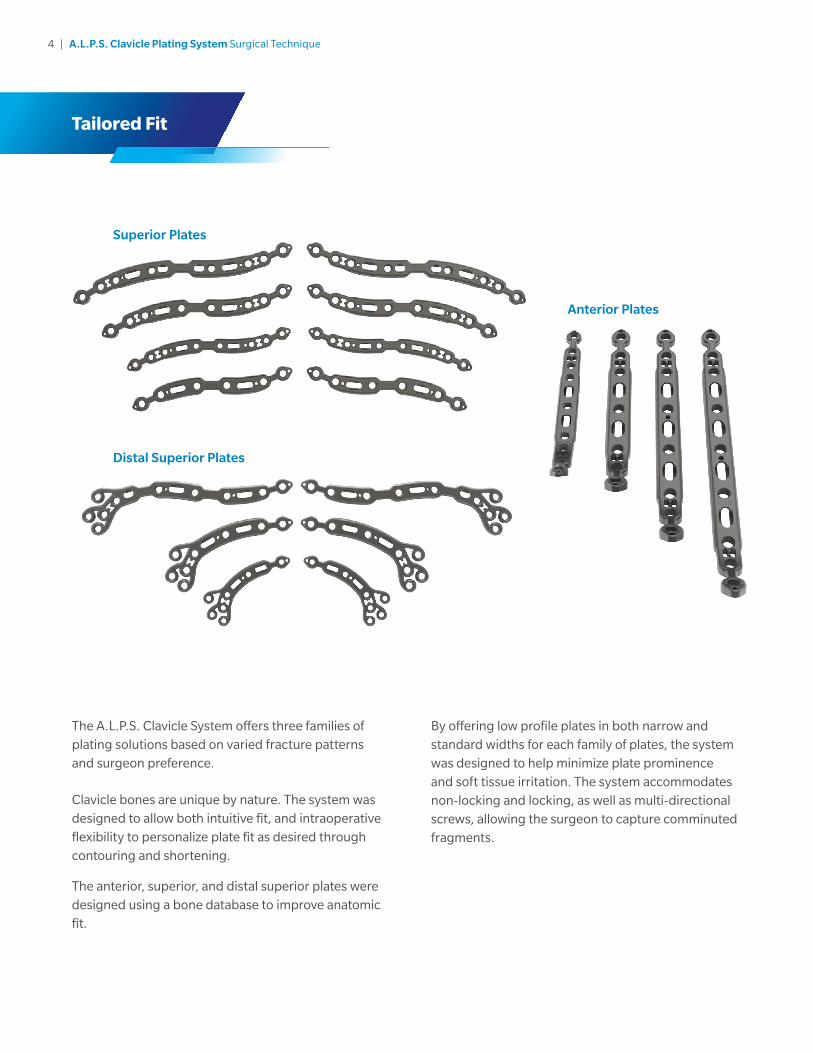
The A.L.P.S. Clavicle System offers three families of plating solutions based on varied fracture patterns and surgeon preference.
Clavicle bones are unique by nature. The system was designed to allow both intuitive fit, and intraoperative flexibility to personalize plate fit as desired through contouring and shortening.
The anterior, superior, and distal superior plates were designed using a bone database to improve anatomic fit.
Tailored Fit
By offering low profile plates in both narrow and standard widths for each family of plates, the system was designed to help minimize plate prominence and soft tissue irritation. The system accommodates non-locking and locking, as well as multi-directional screws, allowing the surgeon to capture comminuted fragments.
Superior Plates
Distal Superior Plates
Anterior Plates

5 | A.L.P.S. Clavicle Plating System Surgical Technique
Intuitive InstrumentationInstrumentation designed to provide precise measurements which allows the surgeon to make appropriate screw selections and to minimize the potential for damage to the surrounding soft tissue.
Systematic EfficiencyThe implants and instruments required to perform a procedure are provided in one case for easy handling, storage and transportation, eliminating the need for multiple implant and instrument trays.
All aspects of this system including the case, implants and the instruments are designed to help maximize efficiency in the O.R.
Each case requires only one drill and one driver following plate selection.
Temporary stabilization of the fracture through medial and lateral K-wire holes as well as the ability to contour the plate in-situ providing systematic efficiency during the procedure.
Intuitive Instrumentation and Systematic Efficiency
6 | A.L.P.S. Clavicle Plating System Surgical Technique
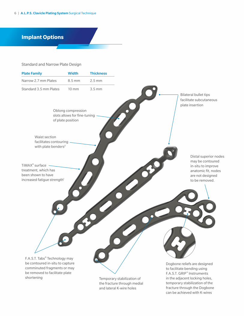
Standard and Narrow Plate Design
Plate Family Width Thickness
Narrow 2.7 mm Plates 8.5 mm 2.5 mm
Standard 3.5 mm Plates 10 mm 3.5 mm
Implant Options
Bilateral bullet tips
facilitate subcutaneous
plate insertion
Distal superior nodes may be contoured in-situ to improve anatomic fit, nodes are not designed to be removed.
TiMAX® surface treatment, which has been shown to have increased fatigue strength1
Waist section facilitates contouring with plate benders2
Oblong compression slots allows for fine-tuning of plate position
Temporary stabilization of the fracture through medial and lateral K-wire holes
Dogbone reliefs are designed to facilitate bending using F.A.S.T. GRIP™ Instruments in the adjacent locking holes, temporary stabilization of the fracture through the Dogbone can be achieved with K-wires
F.A.S.T. Tabs® Technology may be contoured in-situ to capture comminuted fragments or may be removed to facilitate plate shortening

7 | A.L.P.S. Clavicle Plating System Surgical Technique
Screw Options
Designed to achieve optimal fixation with tapered, triple lead locking, low profile non-locking, and multi-directional screw options:
The Classic cobalt chrome multi-directional screws allow for up to a 20°cone of angulation on the 2.7 mm screws, and up to 25° cone of angulation on the 3.5 mm screws.
A.L.P.S. Classic Cobalt Chrome 2.7 mm Screw
A.L.P.S. Classic Cobalt Chrome 3.5 mm Screw
2.7
mm
No
n-Lo
cking
Ti S
crew
2.7
mm
Lockin
g T
i Screw
2.7
mm
Mu
lti-Directio
nal C
oC
r Screw
20º
3.5
mm
No
n-lo
cking
Ti S
crew
3.5
mm
Lockin
g T
i Screw
3.5
mm
Mu
lti-Directio
nal C
oC
r Screw
A.L.P.S. Classic Screw Set
25º

8 | A.L.P.S. Clavicle Plating System Surgical Technique
Key Instrument Features
Short Drill
• Limits the drill travel to help surgeons reduce the likelihood of damaging nearby soft tissue structures.
A.L.P.S. Technology which utilizes:
• F.A.S.T. GRIP Instruments which function as:
– Fixed angle drill guides
– Handles for easy plate placement
• Plate benders for in-situ plate contouring2 or removal of F.A.S.T. Tabs for plate shortening
Tip: Protection of the neuromuscular
structures during drilling may also be
facilitated by using a Crego Elevator beneath
the clavicle as a drill protector.
9 | A.L.P.S. Clavicle Plating System Surgical Technique
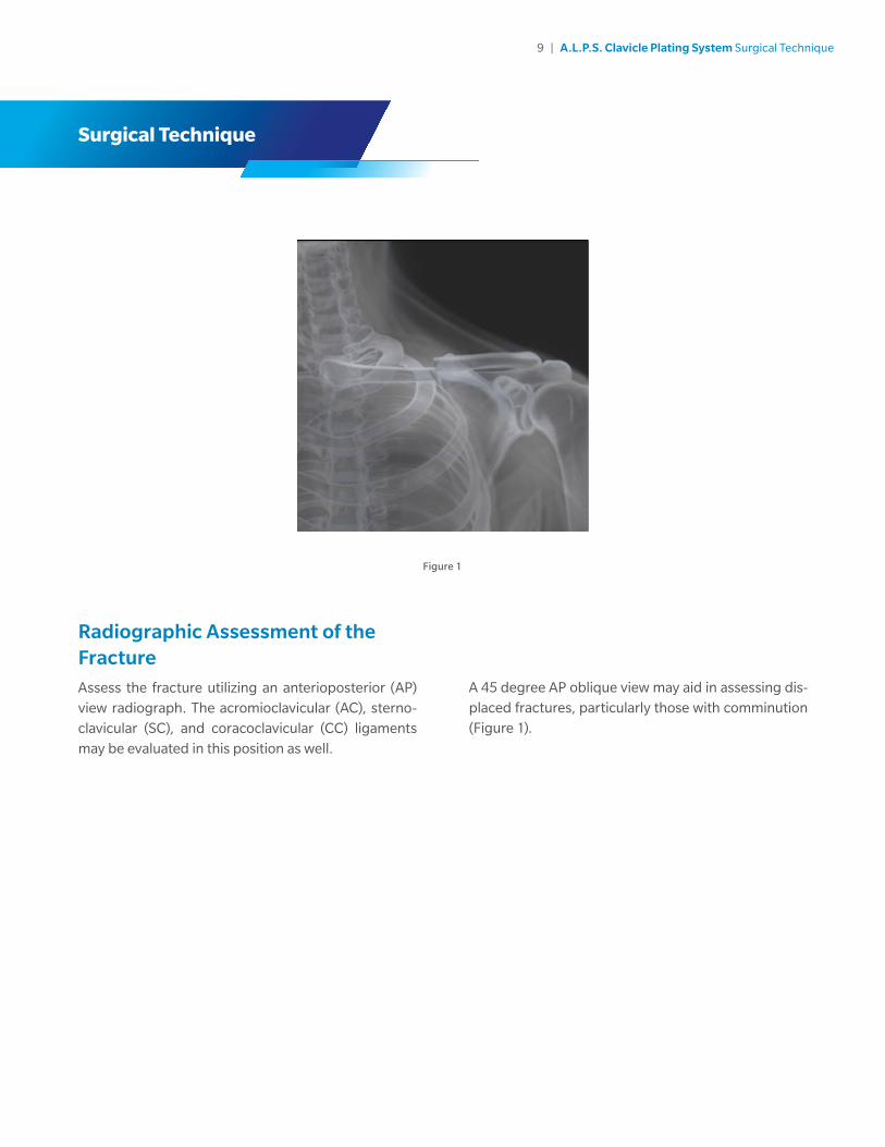
Radiographic Assessment of the FractureAssess the fracture utilizing an anterioposterior (AP) view radiograph. The acromioclavicular (AC), sterno-clavicular (SC), and coracoclavicular (CC) ligaments may be evaluated in this position as well.
Figure 1
Surgical Technique
A 45 degree AP oblique view may aid in assessing dis-placed fractures, particularly those with comminution (Figure 1).
10 | A.L.P.S. Clavicle Plating System Surgical Technique
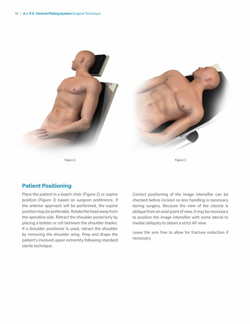
Patient PositioningPlace the patient in a beach chair (Figure 2) or supine position (Figure 3) based on surgeon preference. If the anterior approach will be performed, the supine position may be preferable. Rotate the head away from the operative side. Retract the shoulder posteriorly by placing a bolster or roll between the shoulder blades. If a shoulder positioner is used, retract the shoulder by removing the shoulder wing. Prep and drape the patient’s involved upper extremity following standard sterile technique.
Correct positioning of the image intensifier can be checked before incision so less handling is necessary during surgery. Because the view of the clavicle is oblique from an axial point of view, it may be necessary to position the image intensifier with some lateral to medial obliquity to obtain a strict AP view.
Leave the arm free to allow for fracture reduction if necessary.
Figure 2 Figure 3
11 | A.L.P.S. Clavicle Plating System Surgical Technique
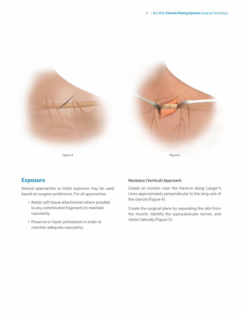
ExposureSeveral approaches to initial exposure may be used based on surgeon preference. For all approaches:
• Retain soft tissue attachments where possible to any comminuted fragments to maintain vascularity.
• Preserve or repair periosteum in order to maintain adequate vascularity.
Necklace (Vertical) Approach
Create an incision near the fracture along Langer’s Lines approximately perpendicular to the long axis of the clavicle (Figure 4).
Create the surgical plane by separating the skin from the muscle. Identify the supraclavicular nerves, and retract laterally (Figure 5).
Figure 4 Figure 5

12 | A.L.P.S. Clavicle Plating System Surgical Technique
Transverse (Horizontal) Approach
Create a medial to lateral transverse incision parallel to the long axis of the clavicle (Figure 6). Incision may be made superior or inferior to the clavicle. Carefully dissect subcutaneously, in an effort to identify and preserve the supraclavicular nerves.
Dissection through platysma will expose the clavicle.
Figure 6

13 | A.L.P.S. Clavicle Plating System Surgical Technique
Minimally Invasive Plate Osteosynthesis (MIPO) Approach: (Anterior Plating-Specific Approach)
Create two incisions perpendicular to the long axis of the clavicle, one medial to the fracture site, and one lateral (Figure 7). Avoid incising over the supraclavicular nerves. Identify and protect these nerves as possible.
Tip: The clavicle fracture may be reduced without exposing the fracture line. Release anterior muscular attachments without detaching the posterior attachments when preparing for anterior plating.
Note: The MIPO approach should only be used with the anterior plate.
Figure 7
14 | A.L.P.S. Clavicle Plating System Surgical Technique
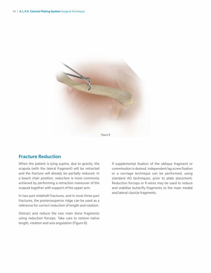
Fracture ReductionWhen the patient is lying supine, due to gravity, the scapula (with the lateral fragment) will be retracted and the fracture will already be partially reduced. In a beach chair position, reduction is most commonly achieved by performing a retraction maneuver of the scapula together with support of the upper arm.
In two part midshaft fractures, and in most three part fractures, the posterosuperior ridge can be used as a reference for correct reduction of length and rotation.
Distract and reduce the two main bone fragments using reduction forceps. Take care to restore native length, rotation and axis angulation (Figure 8).
If supplemental fixation of the oblique fragment or comminution is desired, independent lag screw fixation or a cerclage technique can be performed, using standard AO techniques, prior to plate placement. Reduction forceps or K-wires may be used to reduce and stabilize butterfly fragments to the main medial and lateral clavicle fragments.
Figure 8

15 | A.L.P.S. Clavicle Plating System Surgical Technique
Plate SelectionPlate selection will be based on several factors (Figure 9).
• Patient size, as well as fracture pattern and location will determine plate length and standard or narrow plate profile
• Surgeon preference and anatomic considerations are also contributing factors when determining which specific plate to use
• Ensure the plate length allows for a minimum of 3 screw holes both medial and lateral to the fracture fragments
Figure 9
Anterior Plates
Superior Plates
Distal Superior Plates
Anterior Plates
• Anterior plates are bilateral
Superior Plates
• Superior plates are left and right specific
• Superior mid-shaft plates have different medial and lateral curvatures to improve fit
Note: Left plates only shown in this illustration
Distal Superior Plates
• Distal superior plates are left and right specific.
Note: Left plates only shown in this illustration

16 | A.L.P.S. Clavicle Plating System Surgical Technique
Superior Plate Tip: The medial radius of the clavicle curvature tends to be larger than the lateral radius. The superior plates have been designed similarly. The medial side of the plate has a greater radius of curvature, and is labeled with a “+”. Since the two radii are not equal, rotating the plate 180° on the bone might potentially provide a better fit prior to contouring.
Plate PositioningAfter selecting the appropriate plate, place the plate on the bone to determine if modifications should be made to the shape and length. Position the plate so that there are at least 3 screw holes both medial and lateral to the fracture line.
A F.A.S.T. GRIP Instrument threaded into any locking hole may be used as a handle to aid in plate placement.
Some plate contouring may be made in-situ prior to plate fixation.
Once the desired position and fit has been achieved, use K-wires or reduction forceps to temporarily fix the plate to the bone and to determine proper placement away from the joint space (Figure 10). After provisionally fixing the plate, check the position using fluoroscopy.
Note: There are K-wire holes located near the F.A.S.T. Tabs areas of each plate.
Note: Do NOT permanently implant K-wires through the holes of the plate as they may back out and cause tissue damage. Use of the K-wires allows you to provisionally secure the plates to the anatomy.
Figure 10

17 | A.L.P.S. Clavicle Plating System Surgical Technique
Plate Shortening Using F.A.S.T. GRIP Instruments F.A.S.T. Tabs portion may be removed to shorten the overall plate length of each plate family. To remove, thread the F.A.S.T. GRIP Instruments into F.A.S.T. Tabs portion and the adjacent locking hole, and bend the F.A.S.T. Tabs portion downward towards the bottom of the plate until the bridge between the holes breaks (Figure 11). This shortening method ensures that all rough edges are facing the bone and not the soft tissues.
Figure 11 Figure 12
Feet
Slot
Teeth
Plate Bending Using Plate BendersAll plates with a waist feature can be bent in three planes: convex/concave, planar, and axial.
Plates without a waist feature are designed to only be bent convex/concave.
The plate benders consist of two bending features: the feet and teeth (Figure 12).
18 | A.L.P.S. Clavicle Plating System Surgical Technique
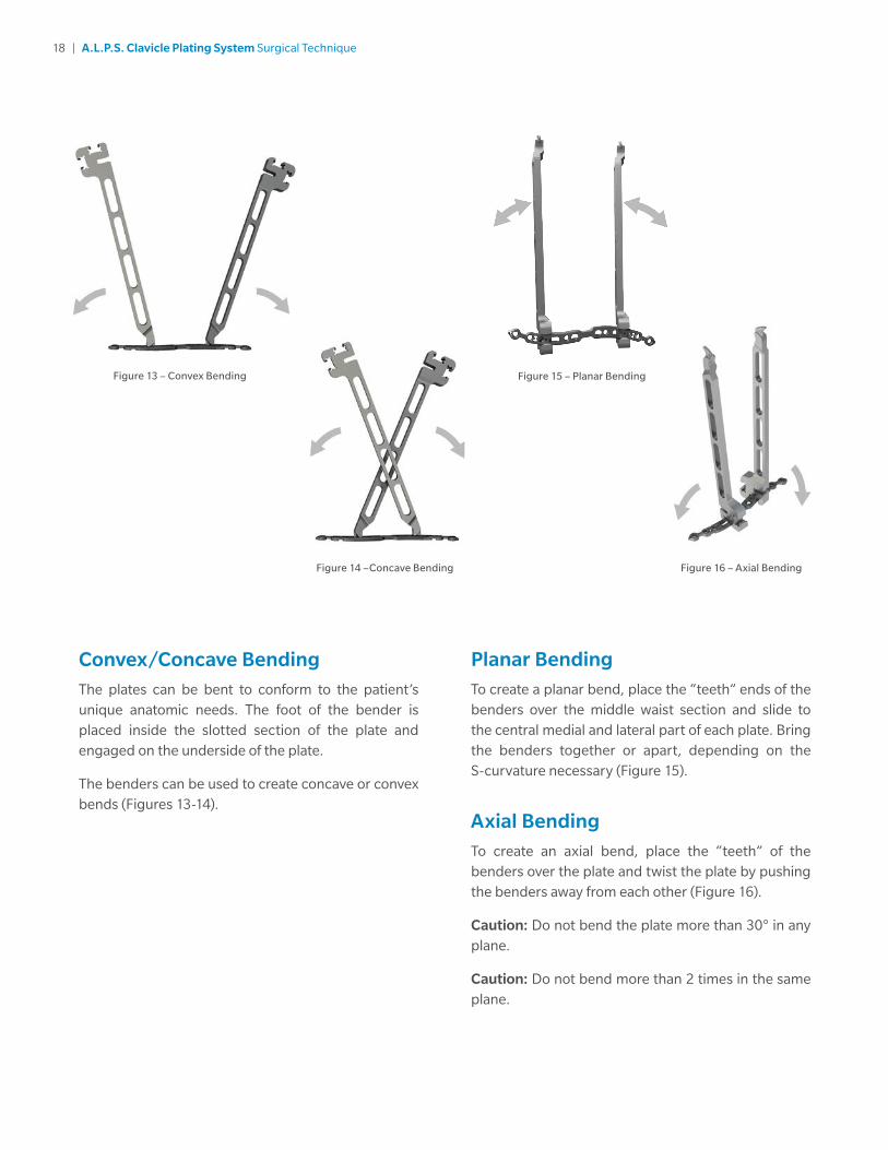
Convex/Concave BendingThe plates can be bent to conform to the patient’s unique anatomic needs. The foot of the bender is placed inside the slotted section of the plate and engaged on the underside of the plate.
The benders can be used to create concave or convex bends (Figures 13-14).
Planar BendingTo create a planar bend, place the “teeth” ends of the benders over the middle waist section and slide to the central medial and lateral part of each plate. Bring the benders together or apart, depending on the S-curvature necessary (Figure 15).
Axial BendingTo create an axial bend, place the “teeth” of the benders over the plate and twist the plate by pushing the benders away from each other (Figure 16).
Caution: Do not bend the plate more than 30° in any plane.
Caution: Do not bend more than 2 times in the same plane.
Figure 16 – Axial Bending
Figure 13 – Convex Bending
Figure 14 –Concave Bending
Figure 15 – Planar Bending

19 | A.L.P.S. Clavicle Plating System Surgical Technique
Plate Contouring Using F.A.S.T. GRIP InstrumentsF.A.S.T. GRIP Instruments may be used to contour F.A.S.T. Tabs and distal superior nodes, which can be contoured in two planes: convex/concave and axial. This contouring can be done using the F.A.S.T. GRIP Instruments in-situ if so desired.
F.A.S.T. GRIP Instruments may also be used to contour the plate around the dogbone relief in the convex/concave plane. To do this, thread the F.A.S.T. GRIP Instruments into adjacent locking holes and impart the bends as necessary (Figure 17).
Figure 17
Note: The plates may be contoured using a combination of a plate bender and a F.A.S.T. Grip instrument.
Note: There are K-wire holes located near the F.A.S.T. Tabs areas of each plate.
Caution: Do not contour the plate more than 30° in any plane.
Caution: Do not contour more than 2 times in the same plane.
Caution: F.A.S.T. GRIP Instruments cannot contour the shaft portion of the plates.
20 | A.L.P.S. Clavicle Plating System Surgical Technique
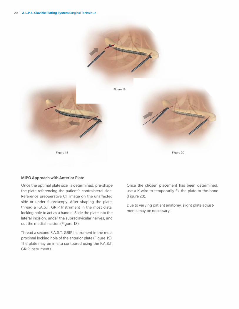
MIPO Approach with Anterior Plate
Once the optimal plate size is determined, pre-shape the plate referencing the patient’s contralateral side. Reference preoperative CT image on the unaffected side or under fluoroscopy. After shaping the plate, thread a F.A.S.T. GRIP Instrument in the most distal locking hole to act as a handle. Slide the plate into the lateral incision, under the supraclavicular nerves, and out the medial incision (Figure 18).
Thread a second F.A.S.T. GRIP Instrument in the most proximal locking hole of the anterior plate (Figure 19). The plate may be in-situ contoured using the F.A.S.T. GRIP Instruments.
Once the chosen placement has been determined, use a K-wire to temporarily fix the plate to the bone (Figure 20).
Due to varying patient anatomy, slight plate adjust-ments may be necessary.
Figure 18 Figure 20
Figure 19
21 | A.L.P.S. Clavicle Plating System Surgical Technique
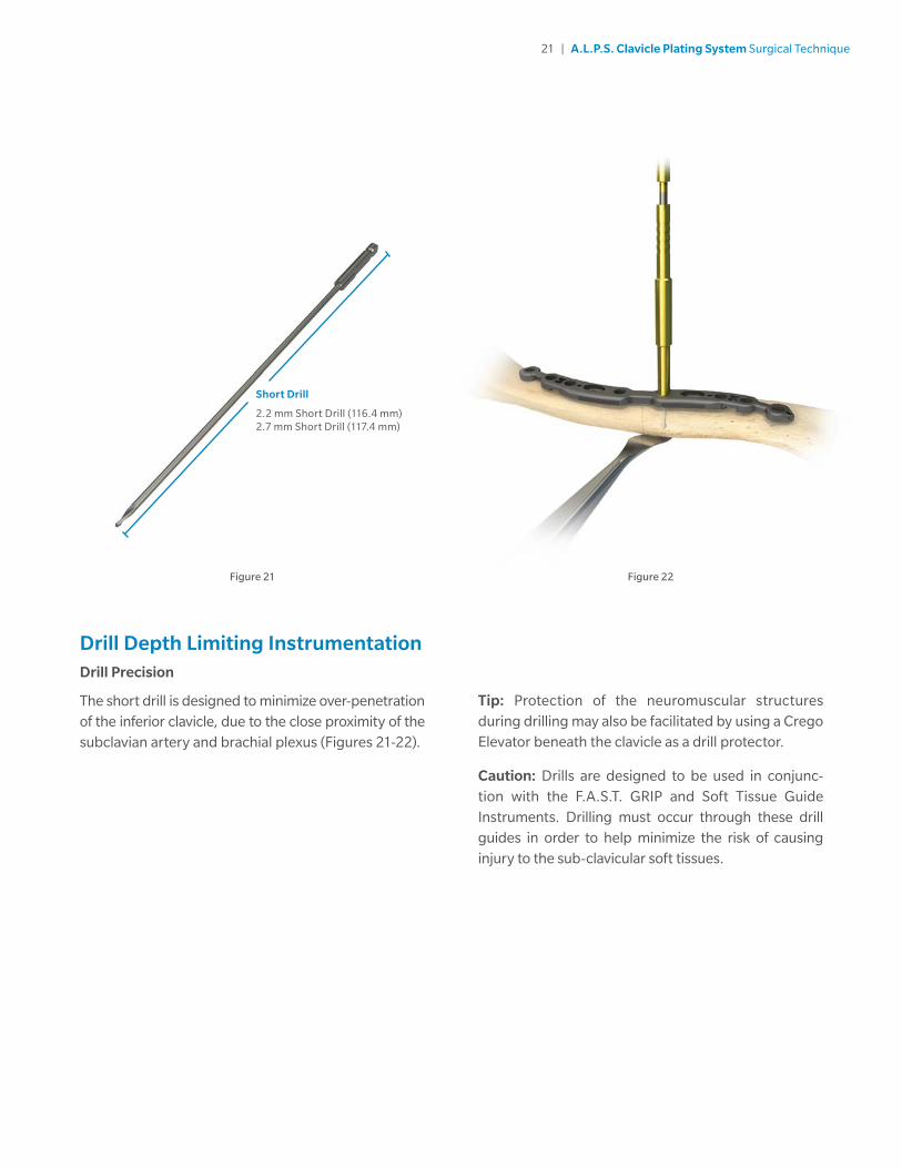
Drill Depth Limiting InstrumentationDrill Precision
The short drill is designed to minimize over-penetration of the inferior clavicle, due to the close proximity of the subclavian artery and brachial plexus (Figures 21-22).
Tip: Protection of the neuromuscular structures during drilling may also be facilitated by using a Crego Elevator beneath the clavicle as a drill protector.
Caution: Drills are designed to be used in conjunc-tion with the F.A.S.T. GRIP and Soft Tissue Guide Instruments. Drilling must occur through these drill guides in order to help minimize the risk of causing injury to the sub-clavicular soft tissues.
Figure 22Figure 21
Short Drill
2.2 mm Short Drill (116.4 mm)2.7 mm Short Drill (117.4 mm)
22 | A.L.P.S. Clavicle Plating System Surgical Technique
Screw InsertionStandard plates utilize only 3.5 mm A.L.P.S. Classic Screws and narrow plates utilize only 2.7 mm Classic screws.
Determine the combination of screws to be used for fixation. If a combination of locking and non-locking screws will be used, non-locking cortical screws should be inserted first to ensure the plate has appropriate bone contact. Insert a minimum of 3 bi-cortical screws both medial and lateral to the fracture.
Note: Non-locking screws may also be used in locking hole positions.
Note: Locking and multi-directional screws cannot be used in oblong compression slots.
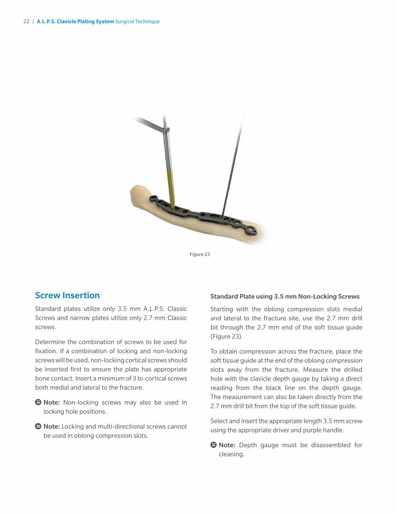
Standard Plate using 3.5 mm Non-Locking Screws
Starting with the oblong compression slots medial and lateral to the fracture site, use the 2.7 mm drill bit through the 2.7 mm end of the soft tissue guide (Figure 23).
To obtain compression across the fracture, place the soft tissue guide at the end of the oblong compression slots away from the fracture. Measure the drilled hole with the clavicle depth gauge by taking a direct reading from the black line on the depth gauge. The measurement can also be taken directly from the 2.7 mm drill bit from the top of the soft tissue guide.
Select and insert the appropriate length 3.5 mm screw using the appropriate driver and purple handle.
Note: Depth gauge must be disassembled for cleaning.
Figure 23

23 | A.L.P.S. Clavicle Plating System Surgical Technique
Standard Plate Using 3.5 mm Locking or Multi-Directional Locking Screws
If the plate is properly aligned on the bone, standard locking screws can be used to secure the plate to the bone. Insert the 2.7 mm F.A.S.T. GRIP Instrument into the locking hole and drill using the 2.7 mm drill bit.
If multi-directional locking is preferred, drill through the 2.7 mm end of the soft tissue guide. The screw will lock into the plate with the drill bit angled off axis anywhere within a 25 degree cone of angulation.
Measure the drilled hole with the clavicle depth gauge by taking a direct reading from the black line on the depth gauge (Figure 24). The measurement can also be taken directly from the 2.7 mm drill bit from the top of the soft tissue guide or F.A.S.T. GRIP Instrument.
Select and insert the appropriate length 3.5 mm locking or multi-directional locking screw using the appropriate driver and purple 2.0 N-m torque limiting handle (Figure 25). To ensure that the screw is fully seated in the plate, insert the screw until the handle clicks.
If inserting the screw under power, use the 2.0 N-m torque limiting power adapter with the appropriate driver to prevent over tightening and plate rotation as the screw is locked into the plate. Perform all final screw tightening by hand.
Figure 24 Figure 25

24 | A.L.P.S. Clavicle Plating System Surgical Technique
Figure 26
Narrow Plate using 2.7 mm Non-Locking Screws
Starting with the oblong compression slots medial and lateral to the fracture site, use the 2.2 mm drill bit through the 2.2 mm end of the soft tissue guide (Figure 26). To obtain compression across the fracture, place the soft tissue guide at the end of the oblong compression slot away from the fracture.
Measure the drilled hole with the clavicle depth gauge by taking a direct reading from the black line on the depth gauge. The measurement can also be taken directly from the 2.2 mm drill bit from the top of the soft tissue guide.
Select and insert the appropriate length 2.7 mm non-locking screw using the 1.7 mm square driver and black handle.
Note: Do not use power or torque limiting handles when installing the 2.7 mm non-locking screws.

25 | A.L.P.S. Clavicle Plating System Surgical Technique
Narrow Plate using 2.7 mm Locking or Multi-Directional Locking Screws
If the plate is properly aligned on the bone, standard locking screws can be used to secure the plate to the bone. Insert the 2.2 mm F.A.S.T. GRIP Instruments into the locking hole and drill using the 2.2 mm drill bit.
If multi-directional locking is preferred, drill through the 2.2 mm end of the soft tissue guide. The screw will lock into the plate with the drill bit angled off axis anywhere within a 20 degree cone of angulation.
Measure the drilled hole with the clavicle depth gauge by taking a direct reading from the black line on the depth gauge. The measurement can also be taken directly from the 2.2 mm drill bit from the top of the soft tissue guide or F.A.S.T. GRIP Instruments.
Select and insert the appropriate length 2.7 mm locking screw using the 1.7 mm square driver and black handle (Figures 27-29).
Note: Do not use power or torque limiting handles when installing the 2.7 mm locking or multi-directional screws.
Figure 27 Figure 28
26 | A.L.P.S. Clavicle Plating System Surgical Technique
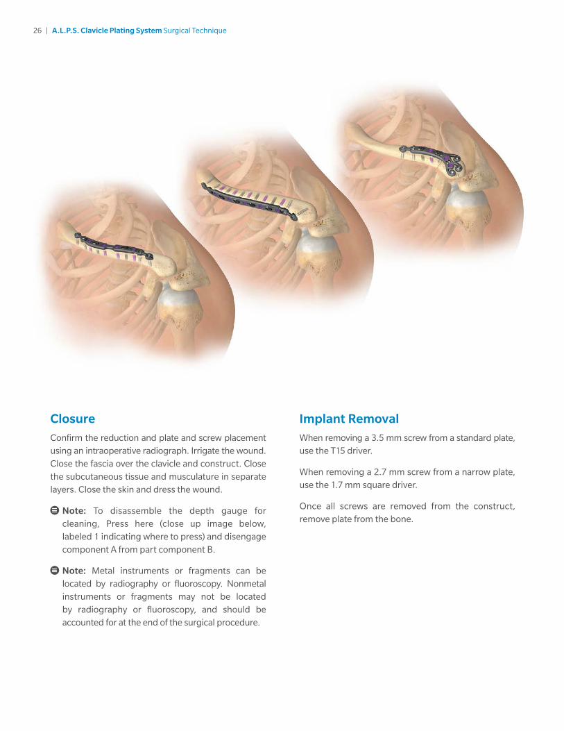
ClosureConfirm the reduction and plate and screw placement using an intraoperative radiograph. Irrigate the wound. Close the fascia over the clavicle and construct. Close the subcutaneous tissue and musculature in separate layers. Close the skin and dress the wound.
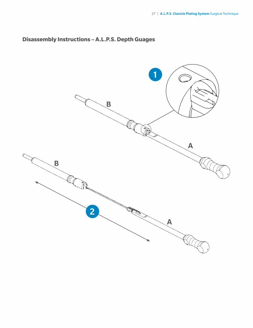
Note: To disassemble the depth gauge for cleaning, Press here (close up image below, labeled 1 indicating where to press) and disengage component A from part component B.
Note: Metal instruments or fragments can be located by radiography or fluoroscopy. Nonmetal instruments or fragments may not be located by radiography or fluoroscopy, and should be accounted for at the end of the surgical procedure.
Implant RemovalWhen removing a 3.5 mm screw from a standard plate, use the T15 driver.
When removing a 2.7 mm screw from a narrow plate, use the 1.7 mm square driver.
Once all screws are removed from the construct, remove plate from the bone.
27 | A.L.P.S. Clavicle Plating System Surgical Technique
1
A
B
2A
B
Disassembly Instructions – A.L.P.S. Depth Guages
28 | A.L.P.S. Clavicle Plating System Surgical Technique
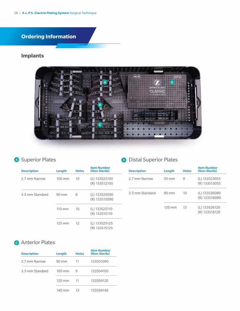
Implants
Ordering Information
DA
Superior Plates
Description Length HolesItem Number (Non-Sterile)
2.7 mm Narrow 100 mm 10 (L) 133522100(R) 133512100
3.5 mm Standard 90 mm 8 (L) 133525090(R) 133515090
110 mm 10 (L) 133525110(R) 133515110
125 mm 12 (L) 133525125(R) 133515125
A
B
Distal Superior Plates
Description Length HolesItem Number (Non-Sterile)
2.7 mm Narrow 55 mm 9 (L) 133523055(R) 133513055
3.5 mm Standard 80 mm 10 (L) 133526080(R) 133516080
120 mm 13 (L) 133526120(R) 133516120
B
C
Anterior Plates
Description Length HolesItem Number (Non-Sterile)
2.7 mm Narrow 90 mm 11 133501090
3.5 mm Standard 100 mm 9 133504100
120 mm 11 133504120
140 mm 13 133504140
C

29 | A.L.P.S. Clavicle Plating System Surgical Technique
A.L.P.S. Classic Screw SetD
1 2
12 3 4 5 6
7
Distal Superior Plates
Description Length HolesItem Number (Non-Sterile)
2.7 mm Narrow 55 mm 9 (L) 133523055(R) 133513055
3.5 mm Standard 80 mm 10 (L) 133526080(R) 133516080
120 mm 13 (L) 133526120(R) 133516120
2.7 mm Locking Ti ScrewsItem Number (Non-Sterile) Description
131227110 Lock Screw Square 2.7mm X 10mm
131227112 Lock Screw Square 2.7mm X 12mm
131227114 Lock Screw Square 2.7Mm X 14Mm
131227116 Lock Screw Square 2.7Mm X 16Mm
131227118 Lock Screw Square 2.7Mm X 18Mm
2.7 mm Non-Locking Ti ScrewsItem Number (Non-Sterile) Description
131227210 LP Non-Lock 2.7mm X 10mm
131227212 LP Non-Lock 2.7mm X 12mm
131227214 LP Non-Lock 2.7mm X 14mm
131227216 LP Non-Lock 2.7mm X 16mm
131227218 LP Non-Lock 2.7mm X 18mm
131227220 LP Non-Lock 2.7mm X 20mm
131227222 LP Non-Lock 2.7mm X 22mm
131227224 LP Non-Lock 2.7mm X 24mm
131227226 LP Non-Lock 2.7mm X 26mm
131227228 LP Non-Lock 2.7mm X 28mm
131227230 LP Non-Lock 2.7mm X 30mm

30 | A.L.P.S. Clavicle Plating System Surgical Technique
A.L.P.S. Classic Screw Set (cont.)
3.5 mm Non-Locking Ti ScrewsItem Number (Non-Sterile) Description
110017710 Screw T15 LP Cort 3.5X10mm NS
110017712 Screw T15 LP Cort 3.5X12mm NS
110017714 Screw T15 LP Cort 3.5X14mm NS
110017716 Screw T15 LP Cort 3.5X16mm NS
110017718 Screw T15 LP Cort 3.5X18mm NS
110017720 Screw T15 LP Cort 3.5X20mm NS
110017722 Screw T15 LP Cort 3.5X22mm NS
110017724 Screw T15 LP Cort 3.5X24mm NS
110017726 Screw T15 LP Cort 3.5X26mm NS
110017728 Screw T15 LP Cort 3.5X28mm NS
110017730 Screw T15 LP Cort 3.5X30mm NS
3.5 mm Multi-Directional CoCr ScrewsItem Number (Non-Sterile) Description
110018010 Screw T15 MD 3.5X10mm NS
110018012 Screw T15 MD 3.5X12mm NS
110018014 Screw T15 MD 3.5X14mm NS
110018016 Screw T15 MD 3.5X16mm NS
110018018 Screw T15 MD 3.5X18mm NS
110018020 Screw T15 MD 3.5X20mm NS
110018022 Screw T15 MD 3.5X22mm NS
110018024 Screw T15 MD 3.5X24mm NS
110018026 Screw T15 MD 3.5X26mm NS
110018028 Screw T15 MD 3.5X28mm NS
110018030 Screw T15 MD 3.5X30mm NS
2.7 mm Multi-Directional CoCr ScrewsItem Number (Non-Sterile) Description
131227310 MD Screw 2.7mm X 10mm
131227312 MD Screw 2.7mm X 12mm
131227314 MD Screw 2.7mm X 14mm
131227316 MD Screw 2.7mm X 16mm
131227318 MD Screw 2.7mm X 18mm
131227320 MD Screw 2.7mm X 20mm
131227322 MD Screw 2.7mm X 22mm
131227324 MD Screw 2.7mm X 24mm
131227326 MD Screw 2.7mm X 26mm
131227328 MD Screw 2.7mm X 28mm
131227330 MD Screw 2.7mm X 30mm
3.5 mm Locking Ti ScrewsItem Number (Non-Sterile) Description
816135010 3.5mm Cort Lock Scr 10mm NS
816135012 3.5mm Cort Lock Scr 12mm NS
816135014 3.5mm Cort Lock Scr 14mm NS
816135016 3.5mm Cort Lock Scr 16mm NS
816135018 3.5mm Cort Lock Scr 18mm NS
816135020 3.5mm Cort Lock Scr 20mm NS
816135022 3.5mm Cort Lock Scr 22mm NS
816135024 3.5mm Cort Lock Scr 24mm NS
816135026 3.5mm Cort Lock Scr 26mm NS
816135028 3.5mm Cort Lock Scr 28mm NS
816135030 3.5mm Cort Lock Scr 30mm NS
3
5
4
6
DescriptionItem Number(Non-Sterile)
1.6MM K-Wire Trochar Tip NS 2335000087
31 | A.L.P.S. Clavicle Plating System Surgical Technique
H
E
C
A
B F
D
IG
K
J M
L
N
OP
Q
R
T
S
U
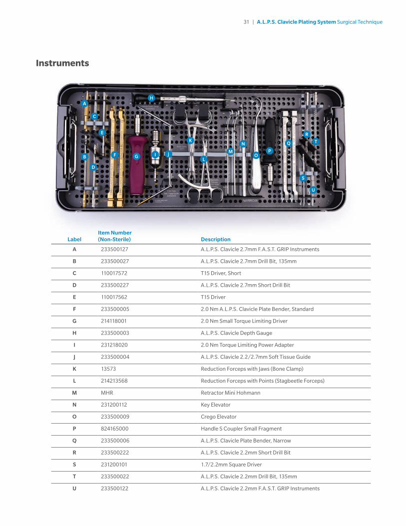
Instruments
LabelItem Number(Non-Sterile) Description
A 233500127 A.L.P.S. Clavicle 2.7mm F.A.S.T. GRIP Instruments
B 233500027 A.L.P.S. Clavicle 2.7mm Drill Bit, 135mm
C 110017572 T15 Driver, Short
D 233500227 A.L.P.S. Clavicle 2.7mm Short Drill Bit
E 110017562 T15 Driver
F 233500005 2.0 Nm A.L.P.S. Clavicle Plate Bender, Standard
G 214118001 2.0 Nm Small Torque Limiting Driver
H 233500003 A.L.P.S. Clavicle Depth Gauge
I 231218020 2.0 Nm Torque Limiting Power Adapter
J 233500004 A.L.P.S. Clavicle 2.2/2.7mm Soft Tissue Guide
K 13573 Reduction Forceps with Jaws (Bone Clamp)
L 214213568 Reduction Forceps with Points (Stagbeetle Forceps)
M MHR Retractor Mini Hohmann
N 231200112 Key Elevator
O 233500009 Crego Elevator
P 824165000 Handle S Coupler Small Fragment
Q 233500006 A.L.P.S. Clavicle Plate Bender, Narrow
R 233500222 A.L.P.S. Clavicle 2.2mm Short Drill Bit
S 231200101 1.7/2.2mm Square Driver
T 233500022 A.L.P.S. Clavicle 2.2mm Drill Bit, 135mm
U 233500122 A.L.P.S. Clavicle 2.2mm F.A.S.T. GRIP Instruments

32 | A.L.P.S. Clavicle Plating System Surgical Technique
Cases and Trays
Item Number (Non-Sterile) Description
231201001 Standard Lid* (An alternative to 233501001)
233501001 A.L.P.S. Clavicle Case – Lid*
233501003 A.L.P.S. Clavicle Case – Base
233501004 A.L.P.S. Clavicle Case – Classic Screw Caddy*
* Not shown
33 | A.L.P.S. Clavicle Plating System Surgical Technique
Indications and Contraindications
INDICATIONSThe A.L.P.S. Clavicle Plating System is indicated for fixation of fractures, osteotomies and non-unions of the clavicle including osteopenic bone.
CONTRAINDICATIONS1. Active infection.
2. Patient conditions including blood supply limitations, insufficient quantity or quality of bone.
3. Patients with mental or neurologic conditions who are unwilling or incapable of following postoperative care instructions.
4. Foreign body sensitivity where material sensitivity is suspected, testing is to be completed prior to implantation of the device.
References
1. Compared to 316L Electropolished Stainless Steel, Type I Anodized titanium, and machined titanium. Citation: Data on file at Biomet. Test # DVA-107504-DVER. Mechanical testing is not necessarily indicative of clinical performance.
2. F.A.S.T. GRIP Instruments are not intended to bend the shaft of the plate.
Tecomet Inc. is the legal manufacturer of parts 214118001, 13573, 214213568, 231200112, and 233500009.
All content herein is protected by copyright, trademarks and other intellectual property rights, as applicable, owned by or licensed to Zimmer Biomet or its affiliates unless otherwise indicated, and must not be redistributed, duplicated or disclosed, in whole or in part, without the express written consent of Zimmer Biomet.
This material is intended for health care professionals. Distribution to any other recipient is prohibited. For product information, including indications, contraindications, warnings, precautions, potential adverse effects and patient counseling information, see the package insert or contact your local representative; visit www.zimmerbiomet.com for additional product information.
Check for country product clearances and reference product specific instructions for use.
Zimmer Biomet does not practice medicine. This technique was developed in conjunction with health care professionals. This document is intended for surgeons and is not intended for laypersons. Each surgeon should exercise his or her own independent judgment in the diagnosis and treatment of an individual patient, and this information does not purport to replace the comprehensive training surgeons have received. As with all surgical procedures, the technique used in each case will depend on the surgeon’s medical judgment as the best treatment for each patient. Results will vary based on health, weight, activity and other variables. Not all patients are candidates for this product and/or procedure. Caution: Federal (USA) law restricts this device to sale by or on the order of a surgeon. Rx only.
©2020 Zimmer Biomet
1608.2-GLBL-en-REV0720
Legal ManufacturerBiomet TraumaP.O. Box 58756 East Bell DriveWarsaw, Indiana 46581-0587USA
www.zimmerbiomet.com
2797
CE mark on a surgical technique is not valid unless there is a CE mark on the product label.