alphaxpress dms sign maintenance manual · august 23, 2006 alphaxpress dms sign maintenance manual...
TRANSCRIPT

AlphaXpress DMS Sign Maintenance Manual
P1501-2 Miami Retrofit
.
Manual part number: 1501610101A
Revision date: August 23, 2006

AlphaXpress DMS Sign Maintenance Manual (part number 1501610101A) August 23, 2006
© Copyright 2006 Adaptive Micro Systems LLC. All rights reserved.
Adaptive Micro Systems
7840 North 86th Street
Milwaukee, WI 53224 USA
414-357-2020
414-357-2029 (fax)
http://www.adaptivedisplays.com
Trademarked names appear throughout this document. Rather than list the names and entities that own the trademarks or insert a trademark symbol with each mention of the trademarked name, the publisher states that it is using names for editorial purposes and to the benefit of the trademark owner with no intention of improperly using the trademark.
The following are trademarks of Adaptive Micro Systems: Adaptive, Alpha, AlphaLert, AlphaNET, AlphaNet plus, AlphaEclipse, AlphaEclipse RoadStar, AlphaEclipse StreetSmart, AlphaPremiere, AlphaTicker, AlphaXpress, AlphaVision, AlphaVision InfoTracker, Automode, BetaBrite, BetaBrite Director, BetaBrite Messaging Software, Big Dot, Director, EZ KEY II, EZ95, PagerNET, PPD, PrintPak, Serial Clock, Smart Alec, Solar, TimeNet.
The distinctive trade dress of this product is a trademark claimed by Adaptive Micro Systems LLC.
Due to continuing product innovation, specifications in this manual are subject to change without notice.
2

August 23, 2006 AlphaXpress DMS Sign Maintenance Manual (part number 1501610101A)
Contents
1.0 Introduction....................................................................................51.1 Purpose .........................................................................................................................................................51.2 Related documentation ..................................................................................................................................51.3 Safety information .........................................................................................................................................5
1.3.1 Equipment symbols ..................................................................................................................51.3.2 Warnings and cautions .............................................................................................................51.3.3 Battery backup ..........................................................................................................................6
2.0 Equipment description.......................................................................72.1 General description ........................................................................................................................................72.2 Outside views.................................................................................................................................................82.3 Inside view.....................................................................................................................................................9
2.3.1 General inside view ...................................................................................................................92.3.2 Controllers ..............................................................................................................................102.3.3 Sign power panels ..................................................................................................................162.3.4 LED driver board .....................................................................................................................17
3.0 Maintenance ................................................................................ 193.1 Physical Inspection ......................................................................................................................................19
3.1.1 Exterior inspection ..................................................................................................................193.1.2 Interior inspection...................................................................................................................19
4.0 Troubleshooting ............................................................................ 214.1 Introduction .................................................................................................................................................214.2 Tools required for Troubleshooting and repair.............................................................................................214.3 Common problems ......................................................................................................................................22
4.3.1 Inoperative AC power..............................................................................................................224.3.2 Inoperative DC power..............................................................................................................224.3.3 Nonfunctional brightness control nonfunctional sign..............................................................234.3.4 Nonfunctional single LED(s) functional sign ...........................................................................244.3.5 Nonfunctional single pixel(s) functional sign ..........................................................................244.3.6 Nonfunctional pixels on entire display board(s) functional sign..............................................24
3
AlphaXpress DMS Sign Maintenance Manual (part number 1501610101A) August 23, 2006
5.0 Part replacement ........................................................................... 255.1 List of field-replaceable parts.......................................................................................................................255.2 Controlling electrostatic discharge (ESD) ....................................................................................................255.3 Sign controller board replacement...............................................................................................................265.4 Power supply replacement...........................................................................................................................29
5.4.1 Sign power supplies................................................................................................................295.4.2 Ground controller power supply .............................................................................................31
5.5 LED driver board replacement .....................................................................................................................325.6 Light sensor replacement ............................................................................................................................35
4

August 23, 2006 AlphaXpress DMS Sign Maintenance Manual (part number 1501610101A)
1.0 Introduction
1.1 Purpose
This manual is intended as a guide for maintenance and repairs considered field serviceable.
This field service manual supplies technical information for service and technical personnel so that they can maintain the equipment at the assembly but not the component level.
1.2 Related documentation
Technical documentation can be found at Adaptive’s web site (http://www.adaptivedisplays.com):
1.3 Safety information
1.3.1 Equipment symbols
1.3.2 Warnings and cautions
Other warnings and cautions are posted in appropriate location throughout this manual.
Table 1: Related documentation
Part # Title Description
TechMemo #05-0005Preventing Electrostatic Discharge (ESD) Damage
Describes the precautions to take to protect electronic components from ESD damage.
15015003DR Reference Wiring Diagram Electrical wiring diagram.
Chassis ground
Introduction 5

AlphaXpress DMS Sign Maintenance Manual (part number 1501610101A) August 23, 2006
1.3.3 Battery backupIn the event of a power loss, two lithium and one, sealed lead-acid batteries provide power to the sign’s two controller boards and ground controller.
NOTE: The backup batteries only provide enough power to operate the sign’s controllers, not the sign’s LED displays.
1.3.3.1 3V lithium backup batteries
One 3V lithium battery is located on each of the sign’s two controller boards
3V lithium battery (Panasonic CR2032 or equivalent).
6 Introduction

August 23, 2006 AlphaXpress DMS Sign Maintenance Manual (part number 1501610101A)
2.0 Equipment description2.1 General description
• Serviceability: Walk in.
• Display size: 27 LED pixel rows x 108 LED pixel columns (see Figure 1).
• Character height: 18 inches, nominal (see Figure 1).
• Character width: 9 inches, nominal (see Figure 1).
• Pitch (distance between each LED pixel): 2.6 inches:
Figure 1: Display size
108 LED pixels
27 LED pixels
Character height= 18” (nominal)
Character width = 9” (nominal)
Figure 2: LED pitch
2.6”
LED pixelcomposed of eight, individual LED lamps.
Equipment description 7

AlphaXpress DMS Sign Maintenance Manual (part number 1501610101A) August 23, 2006
2.2 Outside views
Item Name Description
A Air vents Fans located on the sign floor push air through these vents.
B Light sensor Used for dimming the sign LEDs. There are 3 light sensors used in the sign.
C LEDs Used to display messages.
D Lifting eyeboltsUsed to lift the sign into place for mounting. All four eyebolts must be used to lift this sign (see “2.2 Mechanical installation” on page 8).
E Access door Allows walk-in entry to the inside of the sign.
A
Top view
Front view
Bottom view
Back view
Side view
A
B
B
E
C
E
C
300 in
98 in 94 in
37.5 in
D D
8 Equipment description

August 23, 2006 AlphaXpress DMS Sign Maintenance Manual (part number 1501610101A)
2.3 Inside view
2.3.1 General inside view
Item Name Description
A Load center AC for sign.
B Controller plate Contains sign controller #1 and #2.
C Power panels Provides DC power to display and controller.
A
B
C
Power Panel #1
Power Panel #2
Power Panel #3
Power Panel #4
Power Panel #5
Power Panel #6
Inside front viewProtective panels cover the controller plate, load center, and all the power panels.
Equipment description 9
AlphaXpress DMS Sign Maintenance Manual (part number 1501610101A) August 23, 2006
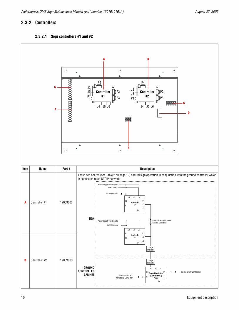
2.3.2 Controllers
2.3.2.1 Sign controllers #1 and #2
Item Name Part # Description
A Controller #1 12069003
These two boards (see Table 2 on page 12) control sign operation in conjunction with the ground controller which is connected to an NTCIP network:
B Controller #2 12069003
Controller#2
Controller#1 P3
P4
P1J3
J4 J5 J6
J2P2
P3
P4
P1J3
J4 J5 J6
J2P2
A
C
B
DF
G
E
J6
P2
P3
P1
J3
J2P4
J5 J4
Controller#1
Light Sensors
Local Access Port (for Laptop Computer)
Central NTCIP Connection
Display Boards
Power Supply Fail Signals
Power Supply Fail Signals RS422 Transmit/Receive Ground Controller
Door Switch
J6
P2
P3
P1
J3
J2P4
J5 J4
Controller#2
J6
P2
P3
P1
J3
J2P4
J5 J4
Ground Controller (Controller #3)
Panel
SurgeProtector
SurgeProtector
SIGN
GROUNDCONTROLLER
CABINET
10 Equipment description
August 23, 2006 AlphaXpress DMS Sign Maintenance Manual (part number 1501610101A)
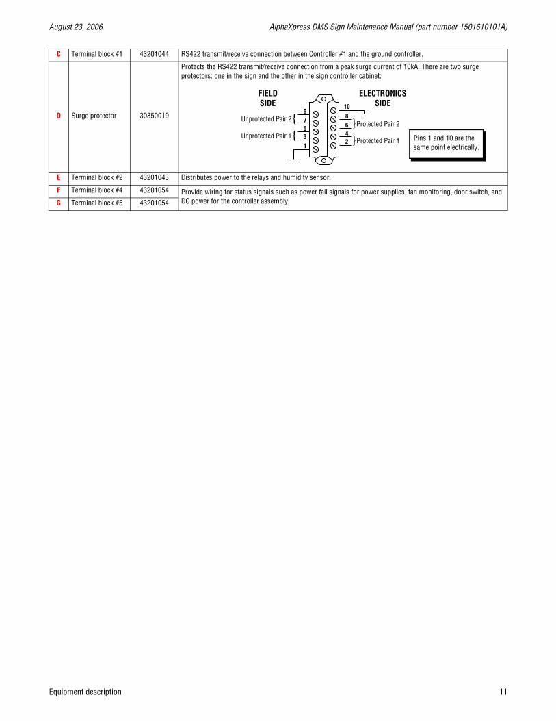
C Terminal block #1 43201044 RS422 transmit/receive connection between Controller #1 and the ground controller.
D Surge protector 30350019
Protects the RS422 transmit/receive connection from a peak surge current of 10kA. There are two surge protectors: one in the sign and the other in the sign controller cabinet:
E Terminal block #2 43201043 Distributes power to the relays and humidity sensor.
F Terminal block #4 43201054 Provide wiring for status signals such as power fail signals for power supplies, fan monitoring, door switch, and DC power for the controller assembly.G Terminal block #5 43201054
Pins 1 and 10 are the same point electrically.
Equipment description 11
AlphaXpress DMS Sign Maintenance Manual (part number 1501610101A) August 23, 2006
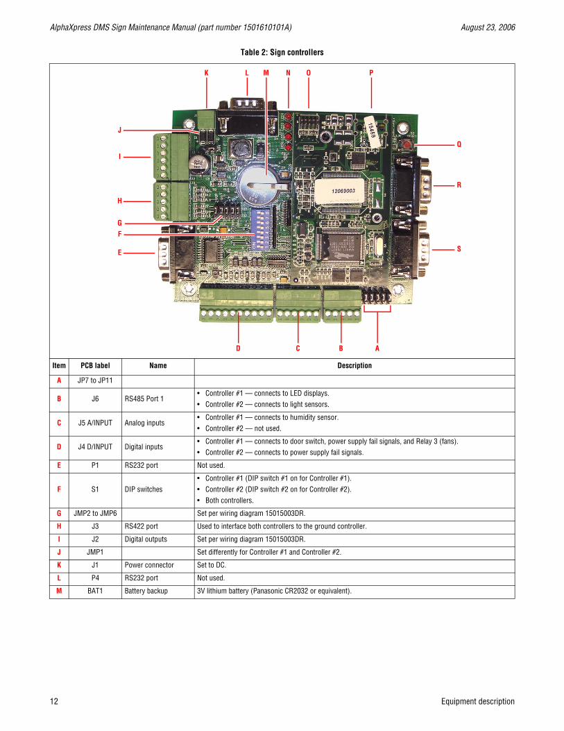
Table 2: Sign controllers
Item PCB label Name Description
A JP7 to JP11
B J6 RS485 Port 1• Controller #1 — connects to LED displays.• Controller #2 — connects to light sensors.
C J5 A/INPUT Analog inputs• Controller #1 — connects to humidity sensor.• Controller #2 — not used.
D J4 D/INPUT Digital inputs• Controller #1 — connects to door switch, power supply fail signals, and Relay 3 (fans).• Controller #2 — connects to power supply fail signals.
E P1 RS232 port Not used.
F S1 DIP switches• Controller #1 (DIP switch #1 on for Controller #1).• Controller #2 (DIP switch #2 on for Controller #2).• Both controllers.
G JMP2 to JMP6 Set per wiring diagram 15015003DR.
H J3 RS422 port Used to interface both controllers to the ground controller.
I J2 Digital outputs Set per wiring diagram 15015003DR.
J JMP1 Set differently for Controller #1 and Controller #2.
K J1 Power connector Set to DC.
L P4 RS232 port Not used.
M BAT1 Battery backup 3V lithium battery (Panasonic CR2032 or equivalent).
ABCD
E
FG
H
I
J
K L N O P
Q
R
S
M
12 Equipment description

August 23, 2006 AlphaXpress DMS Sign Maintenance Manual (part number 1501610101A)
N LED1 to LED4 Diagnostic LEDs
• LED1:
❏ Controller #1 = Heartbeat.
❏ Controller #2 = Heartbeat.
❏ Controller #3 (Ground Controller) = Heartbeat.
• LED2:
❏ Controller #1 = Communications from Controller #3 J3.
❏ Controller #2 = Communications from Controller #3 J3.
❏ Controller #3 (Ground Controller) = Communications from Central/Local port P1 and P2 and Ethernet.
• LED3:
❏ Controller #1 = Flashes when responses come from J6 LED display board.
❏ Controller #2 = Flashes when responses come from J6 light sensor.
❏ Controller #3 (Ground Controller) = Flashes when responses come from sign controller on J6.
• LED4:
❏ Controller #1 = Flashes when transmitting out of J6 LED display board.
❏ Controller #2 = Flashes when transmitting out of J6 light sensor.
❏ Controller #3 (Ground Controller) = Flashes when transmitting goes to sign controllers on J6.
O J5 Programming port
P J4 Ethernet port
Q S2 RESET Controller reset switch Used to do a soft reset on the controller.
R P3 Not used.
S P2 Not used.
Table 2: Sign controllers
Equipment description 13

AlphaXpress DMS Sign Maintenance Manual (part number 1501610101A) August 23, 2006
2.3.2.2 Ground controller (Controller #3) panel
Item Name Part # Description
A Terminal block 43201036 AC power terminal. 3 position x 2, 15mm, 50A.
B Switch 41000233 AC power switch. DPDT, 20A.
C Fuses 48020003 Two, 1.5A, 250V, 3AG, SLO-BLO.
D Surge protector 30350019
Protects the RS422 transmit/receive connection from a peak surge current of 10kA. There are two surge protectors: one in the sign and the other in the sign controller cabinet:
E Terminal block 43201044 RS422 connection to sign controller. 5 position x 2, 8-24AWG, 600V, 50A.
ABCDE
F
G
TX(+)TX(-)
SHIELDRX(+)RX(-)
Pins 1 and 10 are the same point electrically.
14 Equipment description

August 23, 2006 AlphaXpress DMS Sign Maintenance Manual (part number 1501610101A)
F Ground controller 15029101
This board is connected to an NTCIP network and works in conjunction with the two sign controller boards to control sign operation:
G Power supply 40656301
Meanwell SP-200-12 switching power supply, 12VDC output:
J6
P2
P3
P1
J3
J2P4
J5 J4
Controller#1
Light Sensors
Local Access Port (for Laptop Computer)
Central NTCIP Connection
Display Boards
Power Supply Fail Signals
Power Supply Fail Signals RS422 Transmit/Receive Ground Controller
Door Switch
J6
P2
P3
P1
J3
J2P4
J5 J4
Controller#2
J6
P2
P3
P1
J3
J2P4
J5 J4
Ground Controller (Controller #3)
Panel
SurgeProtector
SurgeProtector
SIGN
GROUNDCONTROLLER
CABINET
AC power in:GND, Neutral, and Hot connections
12VDC outputsVoltage output adjustment
Power indicator
Equipment description 15

AlphaXpress DMS Sign Maintenance Manual (part number 1501610101A) August 23, 2006
2.3.3 Sign power panelsThere are 6 power panels in the sign (see “2.3.1 General inside view” on page 9). Each panel contains two, Meanwell PSP-500-12 12VDC output power supplies.
NOTE: Both power supplies may not turn on at the same time if there is not enough display load.
Item Power supply label Name Description
A V+ 12VDC +DC output
B V- 12VDC -
C DC output voltage adjust Adjustment range = 10 to 13.2VDC. Output should be set to 12VDC.
D Input power indicator Green = AC voltage supplied to power supply.
E Signal connector Used for power sharing function, remote sense, and power good signal.
F AC in ground
AC input (90-264VAC, 47-63Hz)G AC/N AC in neutral
H AC/L AC in neutral
DC output side AC input side
Meanwell PSP-500-1212VDC output power supply
Meanwell PSP-500-1212VDC output power supply
Power supply DC output (front view) Power supply AC input (back view)
A B
C
D
E
F G H
16 Equipment description
August 23, 2006 AlphaXpress DMS Sign Maintenance Manual (part number 1501610101A)
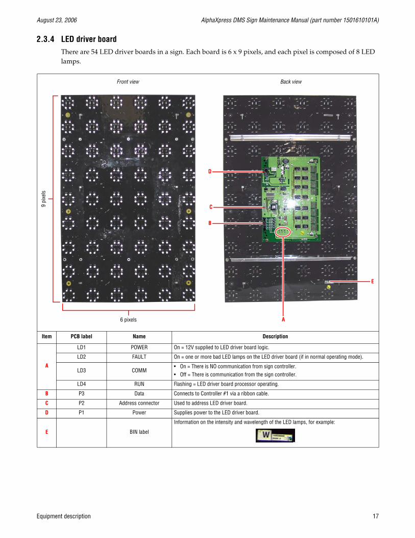
2.3.4 LED driver boardThere are 54 LED driver boards in a sign. Each board is 6 x 9 pixels, and each pixel is composed of 8 LED lamps.
Item PCB label Name Description
A
LD1 POWER On = 12V supplied to LED driver board logic.
LD2 FAULT On = one or more bad LED lamps on the LED driver board (if in normal operating mode).
LD3 COMM• On = There is NO communication from sign controller.• Off = There is communication from the sign controller.
LD4 RUN Flashing = LED driver board processor operating.
B P3 Data Connects to Controller #1 via a ribbon cable.
C P2 Address connector Used to address LED driver board.
D P1 Power Supplies power to the LED driver board.
E BIN label
Information on the intensity and wavelength of the LED lamps, for example:
Front view Back view
6 pixels
9 pi
xels
A
E
B
D
C
Equipment description 17

AlphaXpress DMS Sign Maintenance Manual (part number 1501610101A) August 23, 2006
THIS PAGE INTENTIONALLY BLANK
18 Equipment description
August 23, 2006 AlphaXpress DMS Sign Maintenance Manual (part number 1501610101A)
3.0 Maintenance
3.1 Physical Inspection
3.1.1 Exterior inspection
• Check for any physical damage to the exterior of the sign.
• Check for any physical damage to the interior of the sign.
• Check for loose nuts, bolts, hinges, doors, etc. on the sign.
• Check the electronics for foreign debris and general cleanliness.
• Check the interior of the sign for foreign debris and general cleanliness.
• Check the exterior of the sign for general cleanliness.
• Check the LEDs of the sign for general cleanliness and visibility.
3.1.2 Interior inspection
• Check for any obvious physical damage to the interior.
• Check for loose nuts, bolts, hinges, doors, and so on.
• Check the electronics for foreign debris and general cleanliness.
• Make sure the sign’s drain holes are not plugged.
Maintenance 19

AlphaXpress DMS Sign Maintenance Manual (part number 1501610101A) August 23, 2006
THIS PAGE INTENTIONALLY BLANK
20 Maintenance

August 23, 2006 AlphaXpress DMS Sign Maintenance Manual (part number 1501610101A)
4.0 TroubleshootingThis chapter contains the LED Variable Message Sign (VMS) Trouble Shooting and a general explanation of how each problem can be isolated through a step by step direction.
4.1 Introduction
Due to the complexity of the electronic equipment, it is impossible to describe every possible malfunction that could occur. The intent of this section is to follow a path from the beginning to the end of each system so that a general understanding of the operating system is established. When the sign is not functioning properly, these procedures should help you access the electronics and isolate the defective component(s) in the sign. The defective components may then be removed and replaced with a known good component. The topics discussed and most common problems that you might experience are listed below.
If none of the procedures suggested in this chapter produce a satisfactory solution, you may contact the Adaptive Micro Systems Service Department at 414-357-2020 during normal business hours.
4.2 Tools required for Troubleshooting and repair
In all cases of troubleshooting and repair some tools are required to perform these tasks. The following is a list of common test equipment and tools required to test, remove and replace a defective PCB and/or piece of hardware:
• DMM (Digital Multi Meter)
• 1/8” slotted screwdriver
• 3/16” slotted screwdriver
• #2 Phillips screwdriver
• #3 Phillips screwdriver
• 3/16” nutdriver
• 1/4” nutdriver
• 3/8” nutdriver
• 7/16” nutdriver
• 6" or 8" slip joint pliers
• Needle nose pliers
• Wire strippers (multi gauge)
Access to the electronics and operating system is required to perform the procedures listed herein. Make sure that you have all codes, keys, combinations, and special entry tools.
Troubleshooting 21

AlphaXpress DMS Sign Maintenance Manual (part number 1501610101A) August 23, 2006
4.3 Common problems
4.3.1 Inoperative AC powerMost common problems to the AC side are as following:
• Cable connection not properly secured or came off
• Bad power supply
• Circuit Breaker tripped
• Corroded terminals
• Blown Lighting Arrestor (TVS)
When following these step-by-step procedures, continue going down the numbered list until the problem has been identified and isolated. While troubleshooting the system, make sure that all cables are properly connected and making positive contact (in some cases loose cables are the cause of the problem).
• Verify AC power to the power panel providing power to the sign controllers.
• Verify AC power to the power supply providing power to the ground controller.
• In the load center, verify that AC power is applied to the power supply boxes across breakers.
• In the power supply panels, verify that AC power is applied to all the power supplies, across input terminals. Reference wiring diagrams (see “2.3.3 Sign power panels” on page 16) for power supply panel view and measure across TB1 and TB2 to verify AC voltage is present.
Observe safety practices because this is HIGH VOLTAGE that you are measuring and could result in serious injury.
• If satisfactory results from each AC power test points have been achieved, continue to the next section. If during the testing a problem is found, repair or replace the component.
4.3.2 Inoperative DC powerThe most common problems to the DC side are the following:
• Cable connection not properly secured.
• Cable connection came off.
• Bad power supply.
• Defective printed circuit board.
• Corroded terminals.
When following these step-by-step procedures, continue going down the numbered list until the problem has been identified and isolated. While troubleshooting the system, make sure that all cables are properly connected and making positive contact (in some cases loose cables are the cause of the problem).
• The DC power is checked after the AC power side has been verified.
• In the power supply panels, verify that the 12VDC power is present at the +V and -V, terminals TB3, and TB4. Orange is V+ and Violet is V-.
22 Troubleshooting
August 23, 2006 AlphaXpress DMS Sign Maintenance Manual (part number 1501610101A)
• In the LED driver board, verify that DC power is present on the LED driver board. Check LED indicator LD1 (labeled POWER). If it is lit, then power is supplied to the board. Also check the power connector for 12VDC. Orange is V+ and Violet is V-.
• Light sensor/temperature sensor board LS0-2. Check +12VDC (pin 11) and GND (pin 9) on the boards.
• In most cases when the sign is inoperative, the problem is with a piece of hardware that causes the sign to blank or prevents data from getting to the sign. If a problem is found during the testing, repair or replace the component.
4.3.3 Nonfunctional brightness control nonfunctional sign
• If one or more photocell sensors are nonfunctional, the sign will still operate. The sign will dim according to ambient light levels unless all three are non-functional.
• Check all connections to and from the photocell sensor board and make sure the cables are connections are ok. Check for 12VDC power at the photocell.
• Check software to make sure the sign is not in a “blank” mode.
• Check the address switch on the photocell and the configuration JUMPERS (J6-JMP7-11) on the controller board.
• Verify light sensors are addressed properly.
• Verify COM LED indicator is flashing on each light sensor.
• To verify each light sensor is working, first make sure that sign is in photocell mode first using Intelligent Control. Then check each sensor separately:
❏ Front light sensor verification:
— Cover the back and top light sensors.
— Using Intelligent Control, check the Status screen to see if a photocell reading is present. If above 2 out of 15, cover the front photocell. The value should decrease to 1. If all is as described, go to top light sensor verification.
— If the value is less than 2 out of 15, shine a floodlight on photocell to saturate the light sensor. The value should change within 30 seconds. If status of the light value increases, continue to top light sensor verification. If status does not increase, then replace the light sensor board.
❏ Top light sensor verification:
— Cover the front and back light sensors.
— Using Intelligent Control, check the Status screen to see if a photocell reading is present. If above 2 out of 15, cover the top photocell. The value should decrease to 1. If all is as described, go to back light sensor verification.
— If the value is below 2 out of 15, shine a floodlight on photocell to saturate the light sensor. The value should change within 30 seconds. If status of the light value increases, continue to back light sensor verification. If status does not increase, then replace the light sensor board.
❏ Back light sensor verification:
— Cover the top and back light sensors.
Troubleshooting 23
AlphaXpress DMS Sign Maintenance Manual (part number 1501610101A) August 23, 2006
— Using Intelligent Control, check the Status screen to see if a photocell reading is present. If above 2 out of 15, cover the back photocell. The value should decrease to 1. If all is as described, all light sensors are working properly.
— If the value is below 2 out of 15, shine a floodlight on photocell to saturate the light sensor. The value should change within 30 seconds. If status of the light value increases, then all light sensors are working. If value doe not increase, then replace the pcb assembly.
• Remove and replace the board.
4.3.4 Nonfunctional single LED(s) functional sign
• Remove and replace the LED driver board containing the bad LED(s).
4.3.5 Nonfunctional single pixel(s) functional sign
• In Intelligent Control, run the Pixel Test to locate where the bad pixel is located.
• Remove and replace the LED driver board containing the bad pixel(s).
4.3.6 Nonfunctional pixels on entire display board(s) functional sign
• In Intelligent Control, run the Pixel Test to locate where the bad pixel(s) is/are located.
• Verify that the DC power supplies are not defective and tests for presence of voltage.
• If the test indicates a bad set of power supplies, remove and replace the power supply supplying power to the display boards. If the voltage at the LED driver board is less than 10.5VDC, this may show pixel failures for the pixel diagnostics.
• If power supplies are OK, remove and replace the LED driver board containing the bad pixel(s).
24 Troubleshooting

August 23, 2006 AlphaXpress DMS Sign Maintenance Manual (part number 1501610101A)
5.0 Part replacement
5.1 List of field-replaceable parts
5.2 Controlling electrostatic discharge (ESD)
This equipment contains components that may be damaged by “static electricity”, or electrostatic discharge. To prevent this from happening, be sure to follow the guidelines in Adaptive TechMemo 00-0005, “Guidelines for Controlling Electrostatic Discharge Damage”, available at Adaptive’s web site at http://www.adaptivedisplays.com.
Table 3: Field-replaceable parts
Part name Page
Sign controllers page 26
Power supplies page 29
LED driver board page 32
Light sensor page 35
Part replacement 25
AlphaXpress DMS Sign Maintenance Manual (part number 1501610101A) August 23, 2006
5.3 Sign controller board replacement
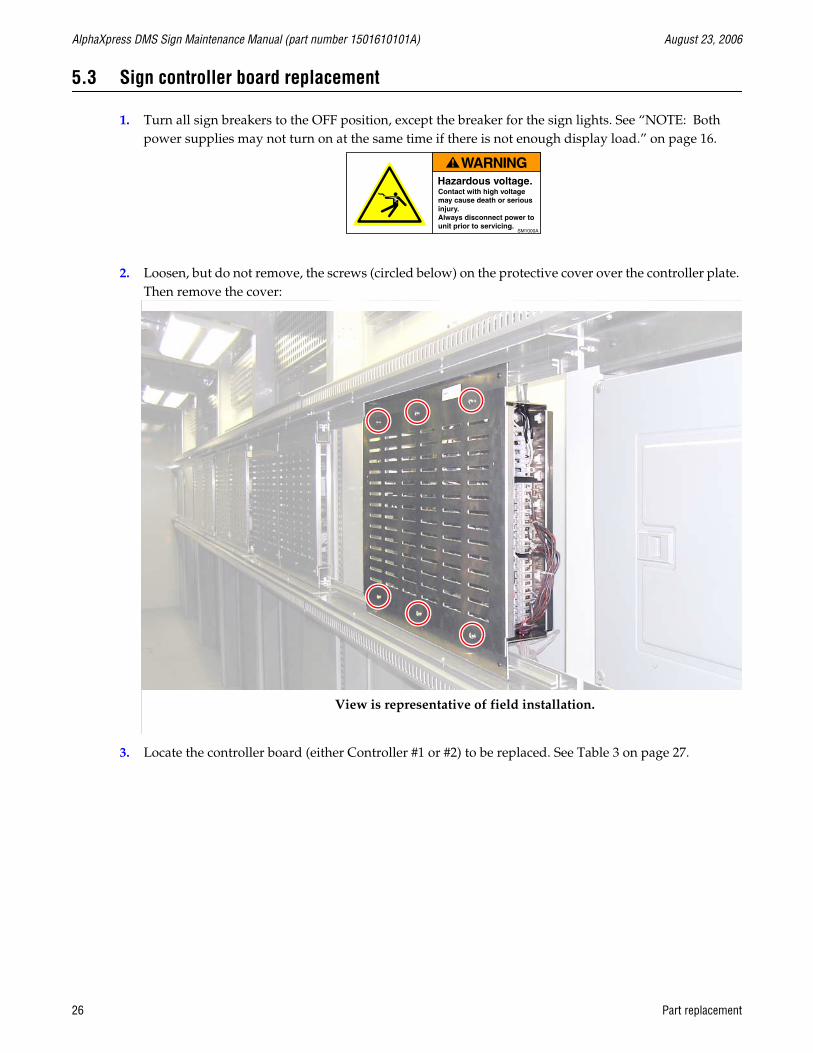
1. Turn all sign breakers to the OFF position, except the breaker for the sign lights. See “NOTE: Both power supplies may not turn on at the same time if there is not enough display load.” on page 16.
2. Loosen, but do not remove, the screws (circled below) on the protective cover over the controller plate. Then remove the cover:
3. Locate the controller board (either Controller #1 or #2) to be replaced. See Table 3 on page 27.
View is representative of field installation.
26 Part replacement
August 23, 2006 AlphaXpress DMS Sign Maintenance Manual (part number 1501610101A)
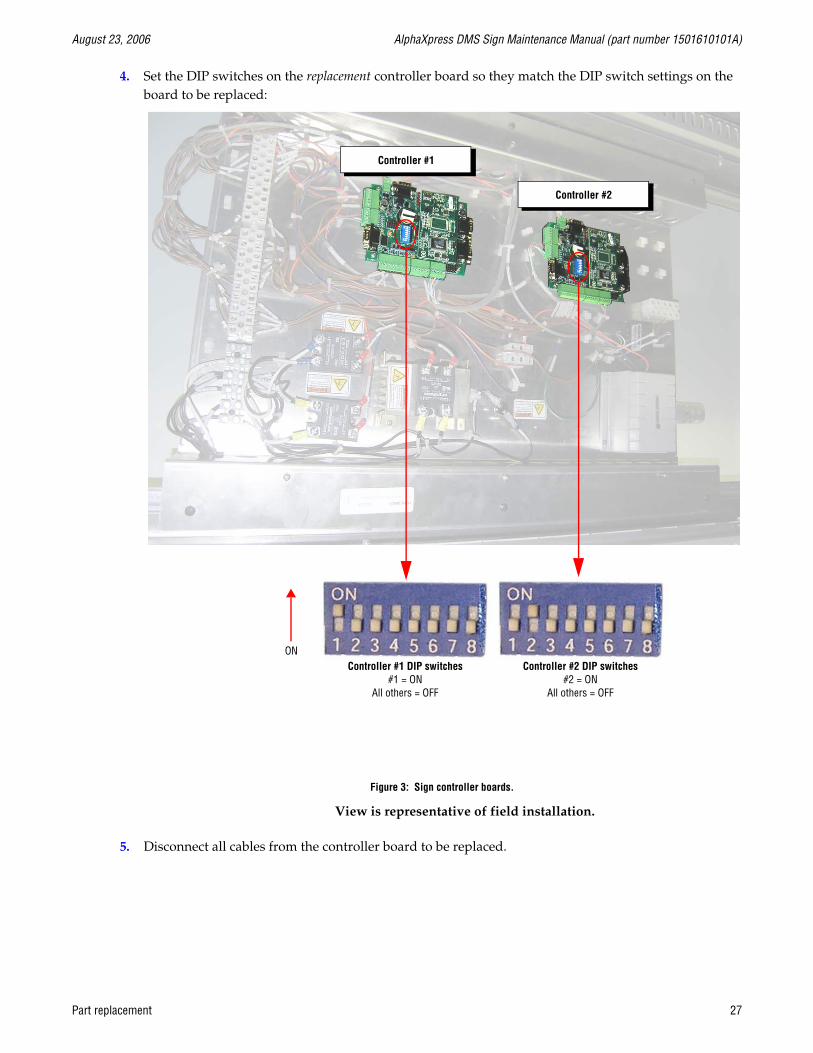
4. Set the DIP switches on the replacement controller board so they match the DIP switch settings on the board to be replaced:
5. Disconnect all cables from the controller board to be replaced.
Controller #2
Figure 3: Sign controller boards.
Controller #1
Controller #2 DIP switches#2 = ON
All others = OFF
Controller #1 DIP switches#1 = ON
All others = OFF
ON
View is representative of field installation.
Part replacement 27

AlphaXpress DMS Sign Maintenance Manual (part number 1501610101A) August 23, 2006
6. Remove the four screws (circled below) that hold the controller board to the sign:
7. Fasten the new controller board to the sign. Then reconnect all the cables to the new board.
8. Reattach the protective cover over the controller plate.
9. Close the sign and apply power to the sign.
28 Part replacement

August 23, 2006 AlphaXpress DMS Sign Maintenance Manual (part number 1501610101A)
5.4 Power supply replacement
Two types of power supplies are used:
• Meanwell PSP-500-12 (see “5.4.1 Sign power supplies” on page 29) — This 12VDC output power supply is used inside the sign.
• Meanwell SP-200-12 (“5.4.2 Ground controller power supply” on page 31) — This is the 12VDC output power supply used on the ground controller plate.
5.4.1 Sign power supplies
1. Turn all sign breakers to the OFF position, except the breaker for the sign lights.
2. Loosen, but do not remove, the screws (circled below) on the protective cover over the power panel. Then remove the cover:
3. Remove all wires from the power supply to be replaced:
View is representative of field installation.
Part replacement 29

AlphaXpress DMS Sign Maintenance Manual (part number 1501610101A) August 23, 2006
DC connections:
❏ V+ (orange-colored wire)
❏ V- (violet-colored wire)
❏ Signal harness
AC connections:
❏ Hot (black wire)
❏ Neutral (white wire)
❏ Ground (green wire)
4. Remove the four screws (circled below) that hold the power supply to the power panel:
5. Fasten the new power supply to the power panel. Then reconnect all the wires to the new power supply.
6. Reattach the protective cover to the power panel.
7. Close the sign and then apply power to the sign.
30 Part replacement
August 23, 2006 AlphaXpress DMS Sign Maintenance Manual (part number 1501610101A)
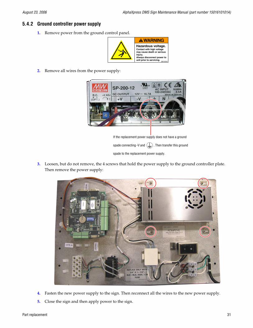
5.4.2 Ground controller power supply
1. Remove power from the ground control panel.
2. Remove all wires from the power supply:
3. Loosen, but do not remove, the 4 screws that hold the power supply to the ground controller plate. Then remove the power supply:
4. Fasten the new power supply to the sign. Then reconnect all the wires to the new power supply.
5. Close the sign and then apply power to the sign.
If the replacement power supply does not have a ground
spade connecting -V and . Then transfer this ground
spade to the replacement power supply.
Part replacement 31

AlphaXpress DMS Sign Maintenance Manual (part number 1501610101A) August 23, 2006
5.5 LED driver board replacement
NOTE: To match the color and intensity of the sign’s LEDs, you may need to determine the BIN letter of the LED driver board to be replaced (see “2.3.4 LED driver board” on page 17).
1. Turn all sign breakers to the OFF position, except the breaker for the sign lights.
2. Locate the LED driver board to be replaced.
3. Remove the protective panel that covers the back of this LED driver board:
Use these hand holds to lift the panel up and then off.
Place the panel out of the way.
32 Part replacement

August 23, 2006 AlphaXpress DMS Sign Maintenance Manual (part number 1501610101A)
4. In the following order, remove these cables from the back of the LED driver board:
❏ Power cable (P1)
❏ Address wire harness (P2)
❏ Communications cable (P3)
Power cable
Data cable
Open each side of the connector before pulling off the data cable or address plug.
Part replacement 33

AlphaXpress DMS Sign Maintenance Manual (part number 1501610101A) August 23, 2006
5. Loosen the six screws (two are circled below) that hold the LED driver board to the sign. Then remove the board:
6. Attach the new LED driver board to the LED panel and tighten down the six screws.
NOTE: The top of the LED driver board is marked with the word “TOP” on the front of the board.
7. Reconnect the cables to the LED driver board (P1 = Power, P2 = Address, P3 = Communication).
8. Reattach the protective panel that covers the back of this LED driver board.
9. Close the sign and apply power to the sign.
34 Part replacement

August 23, 2006 AlphaXpress DMS Sign Maintenance Manual (part number 1501610101A)
5.6 Light sensor replacement
1. Turn all sign breakers to the OFF position, except the breaker for the sign lights.
2. Locate the light sensor to be replaced.
NOTE: Three light sensors are used in the sign. All three are located next to the door of the sign in the globe.
3. Set the address switch on the replacement light sensor board to the setting on the board that will be replaced.
Figure 4: Light sensor
Address switch Wire connector
The arrow on this dial points to the address of the light sensor board, “1” in this case.
Part replacement 35
AlphaXpress DMS Sign Maintenance Manual (part number 1501610101A) August 23, 2006
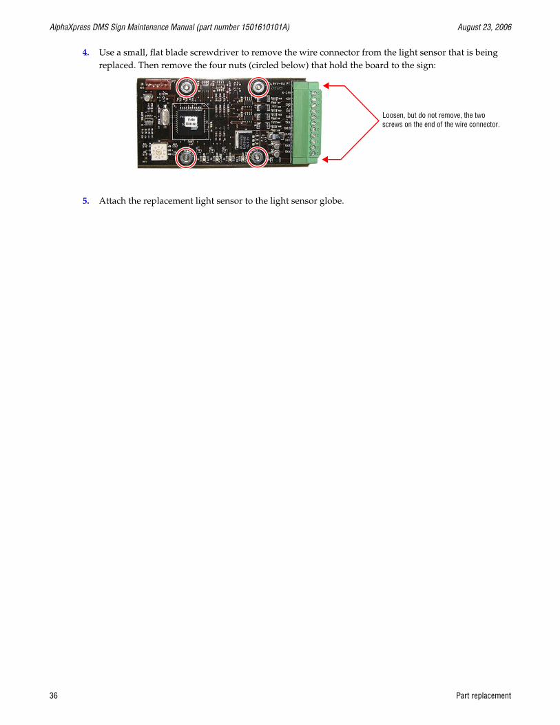
4. Use a small, flat blade screwdriver to remove the wire connector from the light sensor that is being replaced. Then remove the four nuts (circled below) that hold the board to the sign:
5. Attach the replacement light sensor to the light sensor globe.
Loosen, but do not remove, the two screws on the end of the wire connector.
36 Part replacement