alphalink for windows training manual - superdraft … training manual.pdfalphalink for windows...
TRANSCRIPT

1
AlphaLink for Windows Training Manual. This manual is an introduction to AlphaLink for Windows system. It will take the user through the basics of the operation of the software, including starting a new drawing, drawing a component, machining that component and generating the code for the Alpha Lathe from T.S.Harrisons and Sons. Please Note: Throughout this document “Enter” means pressing the Enter key on the keyboard or clicking the left mouse button. Installation: To install the AlphaLink for Windows: Insert the AlphaLink for Windows CD in the CD drive. The CD setup should Autorun, and a series of menu options appear. If it does not, select the Windows “Start” button, and then select “Run”. Select “Browse”, select the CD drive and select “Setup.exe”. Hit OK. Follow the on screen prompts to install the software on the drive you want. Note: If you wish to Un-install the system please use the “Settings” “Control Panel”
“Add/Remove Programs” option. To run the software: A Folder will appear on the desktop of the Windows system you are using. Click on this Folder and three icon options appear in the window:
AlphaWin-S.lnk
This will run the main CADCAM module, which will let you draw and machine a part.
This will send or receive a program to/from the Alpha lathe. You can also Edit and View ISO files in this module.
AlphaUtils.lnk
Readme.lnk
This Read-me document will contain all the latest notes and information about the AlphaLink for Windows system. Please ensure you read this first.
2
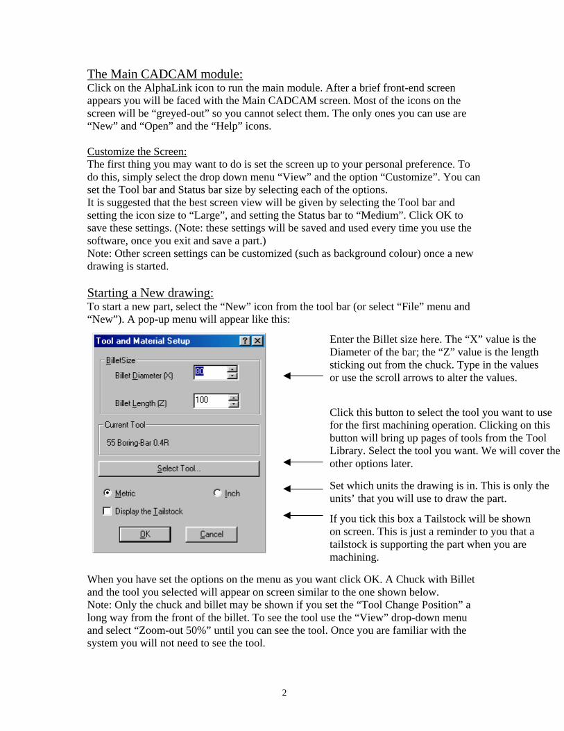
The Main CADCAM module: Click on the AlphaLink icon to run the main module. After a brief front-end screen appears you will be faced with the Main CADCAM screen. Most of the icons on the screen will be “greyed-out” so you cannot select them. The only ones you can use are “New” and “Open” and the “Help” icons. Customize the Screen: The first thing you may want to do is set the screen up to your personal preference. To do this, simply select the drop down menu “View” and the option “Customize”. You can set the Tool bar and Status bar size by selecting each of the options. It is suggested that the best screen view will be given by selecting the Tool bar and setting the icon size to “Large”, and setting the Status bar to “Medium”. Click OK to save these settings. (Note: these settings will be saved and used every time you use the software, once you exit and save a part.) Note: Other screen settings can be customized (such as background colour) once a new drawing is started. Starting a New drawing: To start a new part, select the “New” icon from the tool bar (or select “File” menu and “New”). A pop-up menu will appear like this:
When you have set the options on the menu as you want click OK. A Chuck with Billet and the tool you selected will appear on screen similar to the one shown below. Note: Only the chuck and billet may be shown if you set the “Tool Change Position” a long way from the front of the billet. To see the tool use the “View” drop-down menu and select “Zoom-out 50%” until you can see the tool. Once you are familiar with the system you will not need to see the tool.
Enter the Billet size here. The “X” value is the Diameter of the bar; the “Z” value is the length sticking out from the chuck. Type in the values or use the scroll arrows to alter the values.
Click this button to select the tool you want to use for the first machining operation. Clicking on this button will bring up pages of tools from the Tool Library. Select the tool you want. We will cover the other options later.
Set which units the drawing is in. This is only the units’ that you will use to draw the part.
If you tick this box a Tailstock will be shown on screen. This is just a reminder to you that a tailstock is supporting the part when you are machining.
3
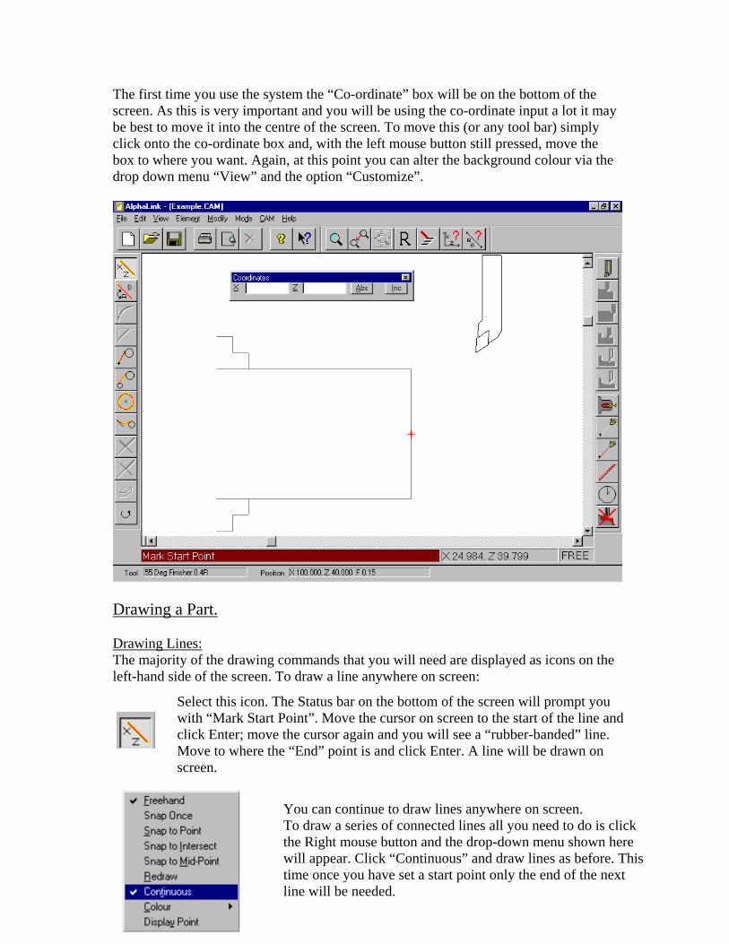
The first time you use the system the “Co-ordinate” box will be on the bottom of the screen. As this is very important and you will be using the co-ordinate input a lot it may be best to move it into the centre of the screen. To move this (or any tool bar) simply click onto the co-ordinate box and, with the left mouse button still pressed, move the box to where you want. Again, at this point you can alter the background colour via the drop down menu “View” and the option “Customize”.
Drawing a Part. Drawing Lines: The majority of the drawing commands that you will need are displayed as icons on the left-hand side of the screen. To draw a line anywhere on screen:
Select this icon. The Status bar on the bottom of the screen will prompt you with “Mark Start Point”. Move the cursor on screen to the start of the line andclick Enter; move the cursor again and you will see a “rubber-banded” line. Move to where the “End” point is and click Enter. A line will be drawn on screen.
You can continue to draw lines anywhere on screen. To draw a series of connected lines all you need to do is click the Right mouse button and the drop-down menu shown here will appear. Click “Continuous” and draw lines as before. This time once you have set a start point only the end of the next line will be needed.
4
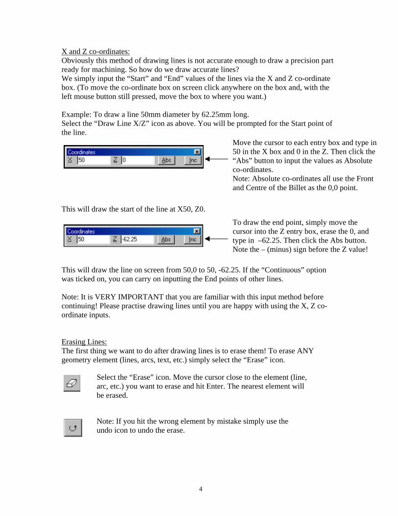
X and Z co-ordinates: Obviously this method of drawing lines is not accurate enough to draw a precision part ready for machining. So how do we draw accurate lines? We simply input the “Start” and “End” values of the lines via the X and Z co-ordinate box. (To move the co-ordinate box on screen click anywhere on the box and, with the left mouse button still pressed, move the box to where you want.) Example: To draw a line 50mm diameter by 62.25mm long. Select the “Draw Line X/Z” icon as above. You will be prompted for the Start point of the line.
This will draw the start of the line at X50, Z0.
This will draw the line on screen from 50,0 to 50, -62.25. If the “Continuous” option was ticked on, you can carry on inputting the End points of other lines. Note: It is VERY IMPORTANT that you are familiar with this input method before continuing! Please practise drawing lines until you are happy with using the X, Z co-ordinate inputs. Erasing Lines: The first thing we want to do after drawing lines is to erase them! To erase ANY geometry element (lines, arcs, text, etc.) simply select the “Erase” icon.
Move the cursor to each entry box and type in 50 in the X box and 0 in the Z. Then click the “Abs” button to input the values as Absolute co-ordinates. Note: Absolute co-ordinates all use the Front and Centre of the Billet as the 0,0 point.
To draw the end point, simply move the cursor into the Z entry box, erase the 0, and type in –62.25. Then click the Abs button. Note the – (minus) sign before the Z value!
Select the “Erase” icon. Move the cursor close to the element (line, arc, etc.) you want to erase and hit Enter. The nearest element will be erased.
Note: If you hit the wrong element by mistake simply use the undo icon to undo the erase.

5
Drawing a Fillet or Chamfer: To put a Fillet arc or Chamfer between two existing lines, use the Fillet or Chamfer icons. Please note: All commands can also be accessed via the drop-down “menus” on the top of the screen. Use the “Modify” menu to find “Fillet” or “Chamfer”.
Obviously for both these commands to work the two lines identified must meet. Drawing Example 1. Using the above commands we will draw a simple shape. 1. Click the “New” icon to start a new drawing. (Don’t save anything you’ve done so far.) Accept the same settings on the “Setup” page as before. 2. Click the “Draw Line X/Z” icon. 3. In the X, Z co-ordinate box enter X40.0 Z0.0 and click the “Abs” button. Press the right-hand mouse button, and ensure “Continuous” is ticked. 4. In the X, Z co-ordinate box enter Z-55 and “Abs”. We will now have on screen:
5. In the X, Z co-ordinate box enter X62.5 and “Abs”. 6. In the X, Z co-ordinate box enter Z-20 and “Inc”. This will draw an “Incremental” line 20mm long. The part should now look like this:
The Fillet and Chamfer commands are very similar. To draw a blend in a corner, click the “Fillet” icon. You will be asked to identify the two lines with the cursor, and then input the size of the Fillet to be blended. To draw a chamfer, you will be asked to identify the two lines with the cursor, and then input the length of the line and angle. Note: The angle and length will be taken referenced to the first line you identify.
6
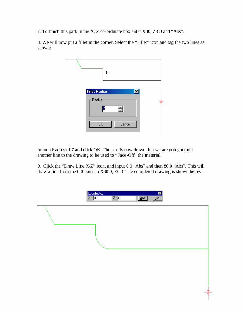
7. To finish this part, in the X, Z co-ordinate box enter X80, Z-80 and “Abs”. 8. We will now put a fillet in the corner. Select the “Fillet” icon and tag the two lines as shown:
Input a Radius of 7 and click OK. The part is now drawn, but we are going to add another line to the drawing to be used to “Face-Off” the material. 9. Click the “Draw Line X/Z” icon, and input 0,0 “Abs” and then 80,0 “Abs”. This will draw a line from the 0,0 point to X80.0, Z0.0. The completed drawing is shown below:
7
Important: Please practise starting new drawings and drawing lines using both “Absolute” and “Incremental” inputs, as well as “Erase”, “Fillet” and the “Chamfer” commands.
Viewing Commands. Here are some more viewing commands that will be useful when using the software.
The above icons are all about viewing the drawing. From left to right they are: Zoom In: This is used to zoom-up around an area of the drawing that you want to see clearly. Mainly used to enlarge small detail of the drawing. You are asked to move the cursor and mark 2 opposite corners. The “window” that you mark will be expanded to fill the screen. Zoom Last: This will bring back to screen the last view you had on screen. If you have looked at 2 views of the drawing you can switch between these views by this icon. Zoom All: This will fit the drawing (and machining moves) onto the screen. Redraw: This simply refreshes the screen. Useful if you erase geometry and part of the line/arc is still shown as “pixel-scatter”. Machining a Part. Taking the part drawn above we will now apply a machining operation to it. Tool Change: Before we can machine the part we must obviously have the correct tool selected. When we started a new drawing we used the “Setup” page to select a tool, and we can just machine with this. But if we don’t have the correct tool:
You will be asked at what position you want the tool to be for a Tool Change. This is very important, as the previous tool used will move to this position for the next tool to be inserted. Note: If a Turret is fitted on the lathe the previous tool will move to this position before the turret indexes.
To Save this part and give it a name, simply click the “Save” icon. The standard Windows “save file” box will appear and you can type in any name to save the drawn part.
Select the “Tool Change” icon.
8
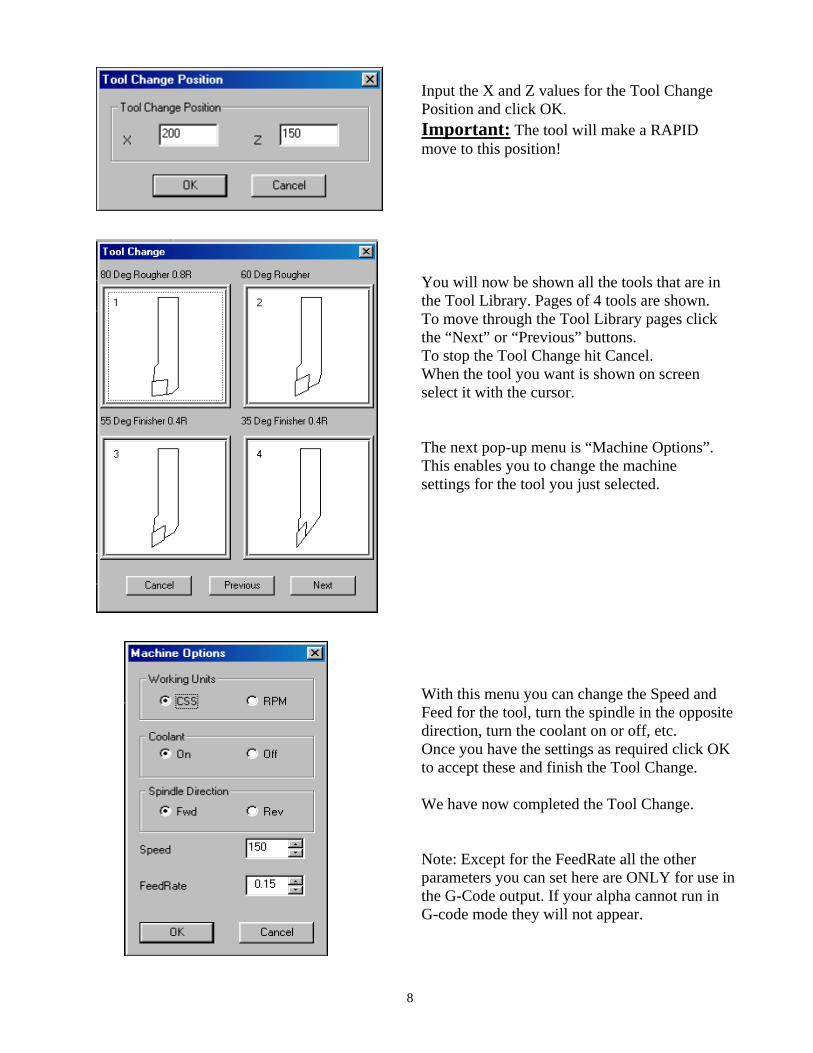
Input the X and Z values for the Tool Change Position and click OK. Important: The tool will make a RAPID move to this position!
You will now be shown all the tools that are in the Tool Library. Pages of 4 tools are shown. To move through the Tool Library pages click the “Next” or “Previous” buttons. To stop the Tool Change hit Cancel. When the tool you want is shown on screen select it with the cursor. The next pop-up menu is “Machine Options”. This enables you to change the machine settings for the tool you just selected.
With this menu you can change the Speed and Feed for the tool, turn the spindle in the opposite direction, turn the coolant on or off, etc. Once you have the settings as required click OK to accept these and finish the Tool Change. We have now completed the Tool Change. Note: Except for the FeedRate all the other parameters you can set here are ONLY for use in the G-Code output. If your alpha cannot run in G-code mode they will not appear.

9
Moving the Tool: The Tool we want to use is now sitting at the Tool Change Position. To move it nearer to the part ready to use we will do a “Rapid Move” close to the billet.
WARNING. Please use these “Move to” commands with care. If you Rapid the tool into the Chuck or Workpiece it will do just that! To move the tool select the Rapid Move icon and click the cursor anywhere on the screen, the tool will move at Rapid to that point. This is useful if we just want the tool to move clear of the part, but it would be more practical to move the tool to an accurate position. To do this we use the X, Z co-ordinate box as before.
Select Rapid Move. In the co-ordinate box input 90, 5 and click Absolute. The Tool will move (as shown above) to X90, Z5. This is 5mm in both directions off the corner of the Billet.
These two icons are very similar. The top one is “Feed Move”. This will move the tool to the cursor position on screen at the current Feedrate. The move will be shown in Yellow. The bottom one is “Rapid Move”. This will move the tool to the cursor at Rapid.The move will be shown in Red.
10
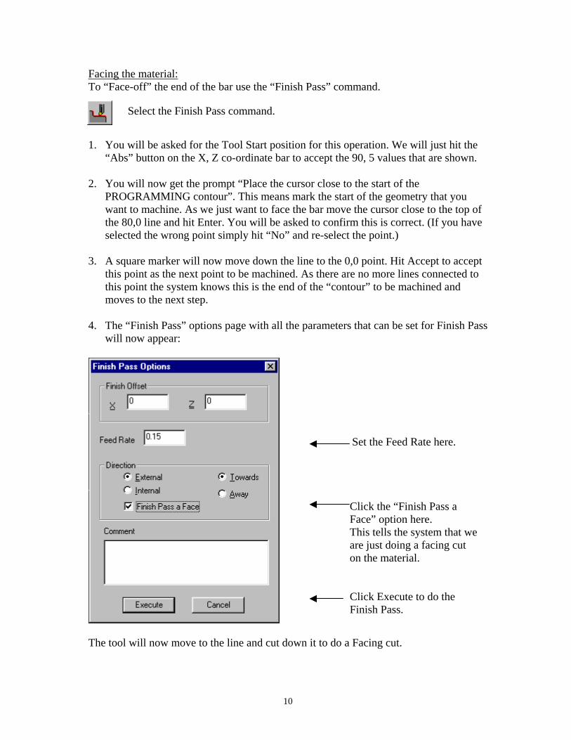
Facing the material: To “Face-off” the end of the bar use the “Finish Pass” command.
1. You will be asked for the Tool Start position for this operation. We will just hit the
“Abs” button on the X, Z co-ordinate bar to accept the 90, 5 values that are shown. 2. You will now get the prompt “Place the cursor close to the start of the
PROGRAMMING contour”. This means mark the start of the geometry that you want to machine. As we just want to face the bar move the cursor close to the top of the 80,0 line and hit Enter. You will be asked to confirm this is correct. (If you have selected the wrong point simply hit “No” and re-select the point.)
3. A square marker will now move down the line to the 0,0 point. Hit Accept to accept
this point as the next point to be machined. As there are no more lines connected to this point the system knows this is the end of the “contour” to be machined and moves to the next step.
4. The “Finish Pass” options page with all the parameters that can be set for Finish Pass
will now appear:
The tool will now move to the line and cut down it to do a Facing cut.
Select the Finish Pass command.
Set the Feed Rate here. Click the “Finish Pass a Face” option here. This tells the system that we are just doing a facing cut on the material. Click Execute to do the Finish Pass.
11
Area Clear: To “Rough-out” the material from this part we will use the “Area Clear” command.
1. You will be asked for the Tool Start position. We will hit the “Abs” button on the X;
Z co-ordinate bar to input the X90, Z5 that we just used. (You can start the tool at any point, but when you run the program on the Alpha lathe the tool must be within 5mm of the point you input for it to continue. Doing it this way you don’t have to move the tool again as we are already there!)
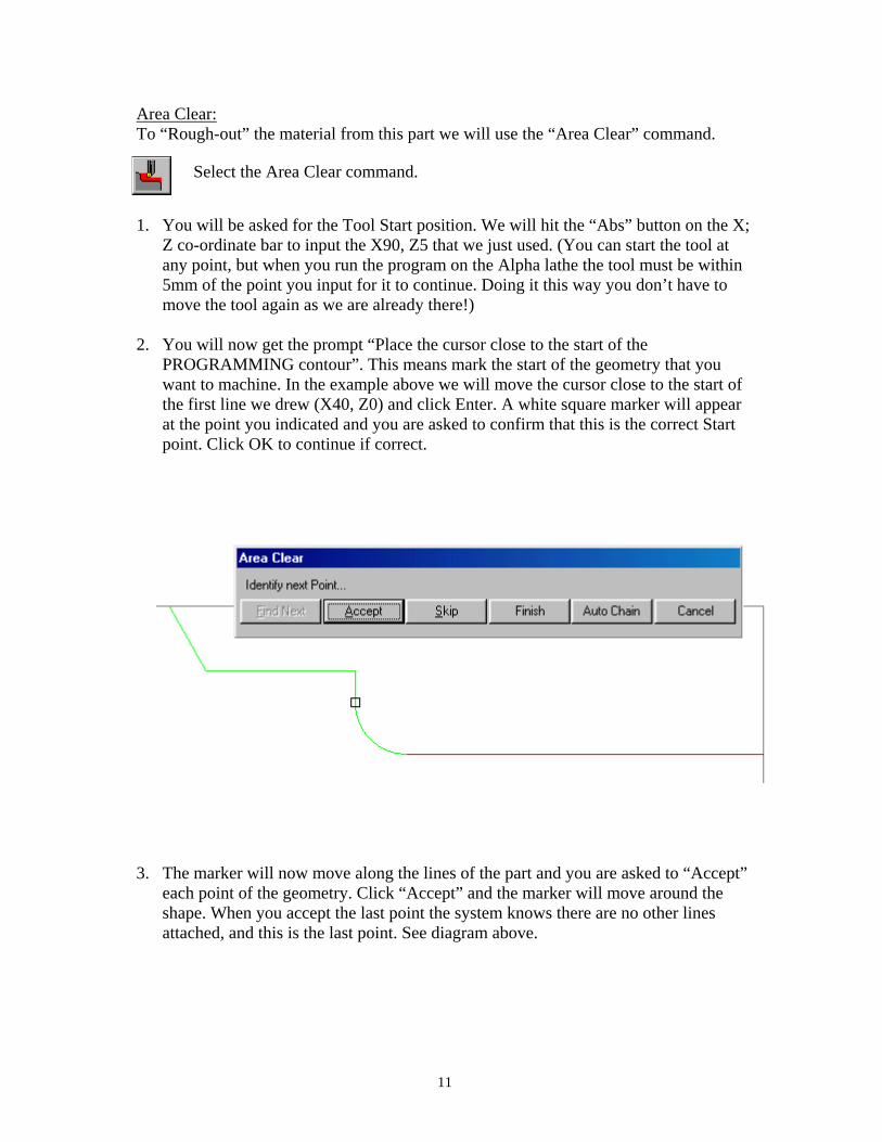
2. You will now get the prompt “Place the cursor close to the start of the
PROGRAMMING contour”. This means mark the start of the geometry that you want to machine. In the example above we will move the cursor close to the start of the first line we drew (X40, Z0) and click Enter. A white square marker will appear at the point you indicated and you are asked to confirm that this is the correct Start point. Click OK to continue if correct.
3. The marker will now move along the lines of the part and you are asked to “Accept”
each point of the geometry. Click “Accept” and the marker will move around the shape. When you accept the last point the system knows there are no other lines attached, and this is the last point. See diagram above.
Select the Area Clear command.

12
4. A pop-up menu will appear with all the Area Clear parameters that you can set:
Depth of Cut = The amount each cut will take off the material from each side. Feedrate = The Feedrate used to carry out this operation. Retract = How much to retract the tool at the end of each cut. Finish Offset = The amount to leave on the part in X and Z. External/Internal, Towards/Away and Front/Face = These options can be set via the tick boxes. See later. Comment = A Comment for this operation can be added in the “Comment” field. This will be added to the text file that can be generated for each part. When you have filled in the Area Clear parameters as required click Execute. The part will then be roughed-out. You are then asked if you want an Automatic “Pre-Finish Pass”. If you click “Yes” the tool will do another pass around the geometry. This is useful to remove any “high” points or steps, and to leave an even amount of material on the part.

13
Notes on Area Clear: 1. If you make a mistake and the part is not machined correctly you can erase the last
operation with the “Delete Last Move” command. This will delete the last move or operation you performed.
2. If you experience any problems with the Area Clear operation, it is a good idea to
delete the Area Clear operation, and re-machine the part. This time using equal offsets for X and Z. Using the same values will ensure an even amount left on the part, and stop any problems with geometry “crossing” by using different X and Z offsets on complex shapes.
3. Another option if experiencing difficulty getting the results you want is to change
the Retract option in Area Clear. Alter the option of Retract to “Straight”, or try “Follow”. This alters the way the tool “looks” at the geometry and may result in a better machining path.
The “External/Internal”, “Towards/Away” and “Front/Face” options for Area Clear set the action the tool will use when cutting: External / Internal. This is obviously very important! If you set this wrong the tool will retract into the part! Towards / Away from Chuck. Tool Cuts Towards Chuck. Tool Cuts Away from Chuck.
If “External” the tool will lift off from the part as shown.
If “Internal” the tool will lift off from the part as shown.
Delete Last Move icon.

14
Front / Face cutting. Front, or Longitudinal cutting. Face cutting. Finish Pass: To do a Finish pass over the part we use the “Finish Pass” command. Using this option we can use the tool to follow the profile of any geometry. First we may want to change the tool. Use the “Tool Change” command as described above to select a new tool. Note: At the tool change we can alter the Feed and Speed, etc. for the finishing operation. Use “Rapid Move” to move the tool back close to the corner of the billet. It is important that the tool is “sitting” outside the billet. (See later.)
When the contour is identified a menu of “Finish Pass” options appears.
Click the Finish Pass icon and identify the contour in exactly the same way as for Area Clear.
Here you can set the X / Z Offset and the Feedrate for the Finish operation. We will alter the offset to 0 and 0, and the Feed to 0.1The direction options are the same as Area Clear, and another comment can be added.
15
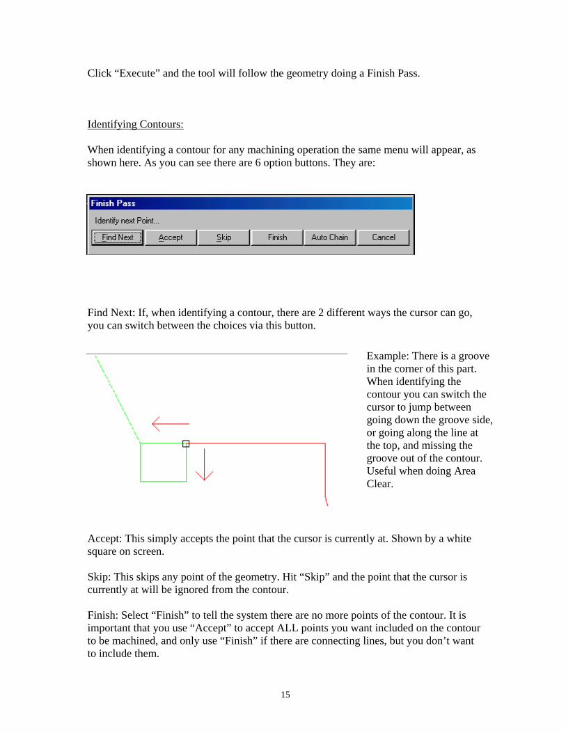
Click “Execute” and the tool will follow the geometry doing a Finish Pass. Identifying Contours: When identifying a contour for any machining operation the same menu will appear, as shown here. As you can see there are 6 option buttons. They are:
Find Next: If, when identifying a contour, there are 2 different ways the cursor can go, you can switch between the choices via this button.
Accept: This simply accepts the point that the cursor is currently at. Shown by a white square on screen. Skip: This skips any point of the geometry. Hit “Skip” and the point that the cursor is currently at will be ignored from the contour. Finish: Select “Finish” to tell the system there are no more points of the contour. It is important that you use “Accept” to accept ALL points you want included on the contour to be machined, and only use “Finish” if there are connecting lines, but you don’t want to include them.
Example: There is a groove in the corner of this part. When identifying the contour you can switch the cursor to jump between going down the groove side, or going along the line at the top, and missing the groove out of the contour. Useful when doing Area Clear.

16
Auto Chain: If the contour you are identifying is a series of lines/arcs with no “branches” or lines to miss-out (skip); select the first point as usual, and then hit “Auto-Chain”. The system will find all further points that are connected. This speeds up the identifying process. Cancel: This will simply cancel the operation you selected. When you have machined the part SAVE THE DRAWING! Do not forget to save your work. If you exit and don’t save the drawing and the machining will be gone! Generate Program. To generate the program file that we will send to the Alpha Lathe: 1. From the drop-down menus on the top of the screen, select “File” and then
“Generate Program”. 2. A screen similar to the one shown here will appear:
3. This output page will vary depend on the version of software you are using. This
obviously relates to the type of Alpha Lathe you are using. The page shown above is for an Alpha-S (and –U) series lathes; but all the outputs are similar. The options are:
Output type: Alpha / G-Code. The programs generated can be used in the Alpha “CAM” mode of running the lathe, or as an ISO G-code program. Click the tick box required and input either: “Alpha” - A Filename. This is displayed on the Alpha screen when the program is used. “G-Code” - A program number. Used on the G-code option of the lathe to file programs. When G-code is selected the Max’ Speed option can be used to set the maximum spindle speed for the G-code program.

17
Re-number Tools: Click this box and you can input a different tool number than the one used in the Tool Library. For instance, you could have used tools 1, 4, and 17 from the library to machine the part on screen, but want to call them tool 1, 2, 3 on the lathe. Click OK and the relevant program will be generated. Please Note: 1. The option “Generate Program” will be “greyed-out” and not useable if you have
altered the drawing in any way until you “Save” the part again. This ensures the part is “current” and you have not done any modifications that are lost when the program is generated.
2. The generated file will be automatically put into the directory:
Alpha programs = \AlphaLink-S\Programs ISO programs = \AlphaLink-S\ISO These can be altered via the menu View Customize Output File location. Here you can set where you want the files generated to be stored.
3. If you generate an ISO program a text file with the machining information will also
be generated. This shows all the tool operations and moves for each operation. The text file will have the same name as the saved part, and an extension .TXT
Help Pages. To get detailed help on each command simply use the Help pages.
Sending To / From the machine. Once a program has been generated you can “Exit” out of the main CADCAM module and use the “Alpha-Utilities” module to send the program to the lathe.
The module will run and a screen with the following options will appear.
Click onto this icon. The question mark will attach itself to the cursor. Move the cursor and click over any icon or menu item. A page will appear with help on how to use the command.
AlphaUtils.lnk
Click on this icon to run the Alpha-Utilities module.
18
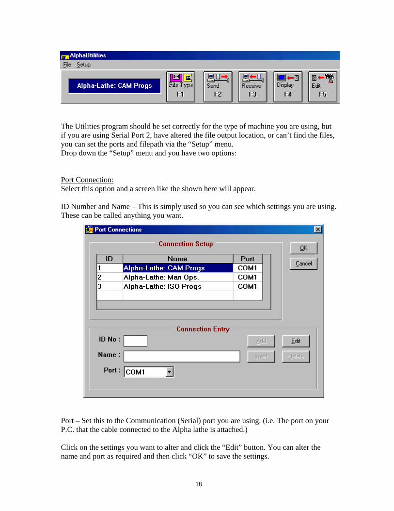
The Utilities program should be set correctly for the type of machine you are using, but if you are using Serial Port 2, have altered the file output location, or can’t find the files, you can set the ports and filepath via the “Setup” menu. Drop down the “Setup” menu and you have two options: Port Connection: Select this option and a screen like the shown here will appear. ID Number and Name – This is simply used so you can see which settings you are using. These can be called anything you want.
Port – Set this to the Communication (Serial) port you are using. (i.e. The port on your P.C. that the cable connected to the Alpha lathe is attached.) Click on the settings you want to alter and click the “Edit” button. You can alter the name and port as required and then click “OK” to save the settings.
19
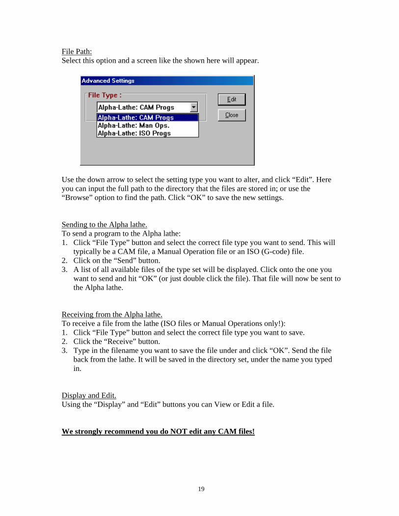
File Path: Select this option and a screen like the shown here will appear.
Use the down arrow to select the setting type you want to alter, and click “Edit”. Here you can input the full path to the directory that the files are stored in; or use the “Browse” option to find the path. Click “OK” to save the new settings. Sending to the Alpha lathe. To send a program to the Alpha lathe: 1. Click “File Type” button and select the correct file type you want to send. This will
typically be a CAM file, a Manual Operation file or an ISO (G-code) file. 2. Click on the “Send” button. 3. A list of all available files of the type set will be displayed. Click onto the one you
want to send and hit “OK” (or just double click the file). That file will now be sent to the Alpha lathe.
Receiving from the Alpha lathe. To receive a file from the lathe (ISO files or Manual Operations only!): 1. Click “File Type” button and select the correct file type you want to save. 2. Click the “Receive” button. 3. Type in the filename you want to save the file under and click “OK”. Send the file
back from the lathe. It will be saved in the directory set, under the name you typed in.
Display and Edit. Using the “Display” and “Edit” buttons you can View or Edit a file. We strongly recommend you do NOT edit any CAM files!
20
Problems communicating with the Alpha Lathe. If you experience problems when communicating with the Alpha lathe here are a few pointers as to what to do. 1. Please ensure you are using a correct cable! Use the cable supplied, or if you have a
different one please check the pin connections are exactly the same as those shown in the AlphaLink Manual.
2. Check that the cable is connected to the Serial port of the Alpha lathe. This is a 25-
pin female port at the back or side of the lathe. Ensure it is connected to a Serial port on the PC.
3. Use the Manual Operations mode of the lathe and save the Manual Operations to the
PC: With the manual operations on screen at the lathe (Stops, Taper or Thread) press the “Edit” button to give you the options of Delete, Save or Load Manual Ops. On the PC select the “Alpha-Utilities” option as shown above. Set the File Type to “Manual Operations”. Click the Receive option and type in a name to save the operations under and hit Enter. The PC will wait to receive the Ops from the lathe. At the lathe, select “Save Operations” and follow the prompts to press Enter. This will send the operations pages in memory out of the serial port back to the PC. If, at the PC you see data arriving (data should be seen on the screen) then the cable and Serial Ports are all working correctly. After the data is sent hit the “Stop” option to stop the transfer onto the PC. The file will be stored. Get the lathe ready to receive by selecting the “Load” option, and send the file you just received on the PC back to the lathe. If all the operations appear as before the communications is working correctly.
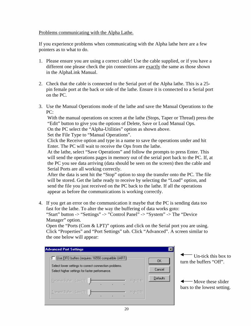
4. If you get an error on the communication it maybe that the PC is sending data too fast for the lathe. To alter the way the buffering of data works goto: “Start” button -> “Settings” -> ”Control Panel” -> “System” -> The “Device Manager” option. Open the “Ports (Com & LPT)” options and click on the Serial port you are using. Click “Properties” and “Port Settings” tab. Click “Advanced”. A screen similar to the one below will appear:
Un-tick this box to turn the buffers “Off”.
Move these slider bars to the lowest setting.

21
Importing a DXF file. To read in a DXF (Data eXchange Format) into the AlphaLink for Windows system: 1. Open a new drawing.
2. The “Open” Window will appear as shown here.
Use the “Files of type” drop-down options and set the type to “Dxf Files”. 3. You can now use the standard Windows open options to find the correct directory
and file you want to open. (A directory called DXF is created when you install the software as a starting point.)
4. Click on the DXF file and it will appear in the graphics window of the software. An
option to “Rotate” the DXF file is now given. Values of 0, 90, 180 and 270 degrees enable you to rotate the DXF image if it was created in the wrong orientation.
5. The DXF geometry is now in the AlphaLink system, BUT because we didn’t enter
the Billet size at the start, as usual, the geometry may not be on the correct billet. To alter this: Select “Modify” and “Billet”. Enter the billet sizes you want here. Obviously you must know the size of the part so you can input a correct sized billet for machining.
6. If the geometry was drawn about the correct 0,0 position the part will appear at the
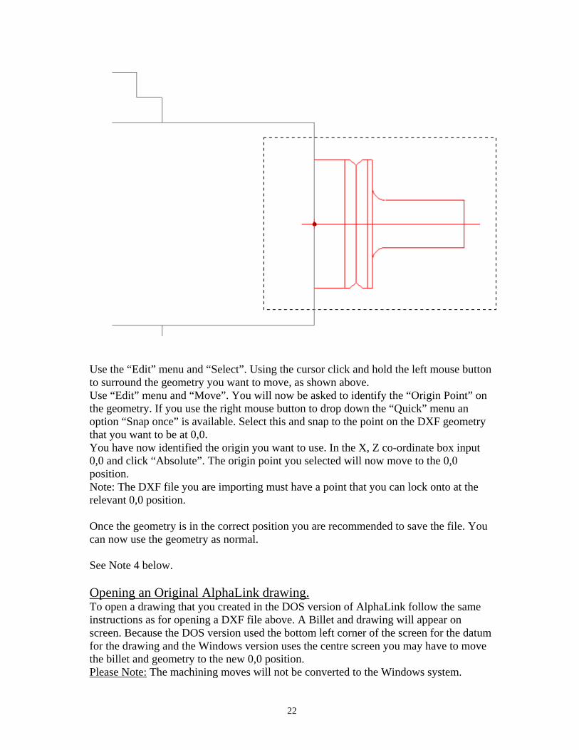
correct 0,0 datum on screen and you are ready to machine it. If the geometry is not at the 0,0 position, as in the example below, you can move it. To do this:
Use this icon to “Open” a file.
22
Use the “Edit” menu and “Select”. Using the cursor click and hold the left mouse button to surround the geometry you want to move, as shown above. Use “Edit” menu and “Move”. You will now be asked to identify the “Origin Point” on the geometry. If you use the right mouse button to drop down the “Quick” menu an option “Snap once” is available. Select this and snap to the point on the DXF geometry that you want to be at 0,0. You have now identified the origin you want to use. In the X, Z co-ordinate box input 0,0 and click “Absolute”. The origin point you selected will now move to the 0,0 position. Note: The DXF file you are importing must have a point that you can lock onto at the relevant 0,0 position. Once the geometry is in the correct position you are recommended to save the file. You can now use the geometry as normal. See Note 4 below. Opening an Original AlphaLink drawing. To open a drawing that you created in the DOS version of AlphaLink follow the same instructions as for opening a DXF file above. A Billet and drawing will appear on screen. Because the DOS version used the bottom left corner of the screen for the datum for the drawing and the Windows version uses the centre screen you may have to move the billet and geometry to the new 0,0 position. Please Note: The machining moves will not be converted to the Windows system.

23
Adding a Tool to the Tool Library. To add a new tool to the Tool Library:
1. Draw the tool on screen. It is a good idea to start a new drawing and draw the tool shape about the 0,0 position. This can be used as the datum for the tool when machining.
2. Select the “Edit” menu and “Select” command. Throw a box around the tool
geometry as shown below. This identifies the lines and arcs.
3. Select “CAM” menu and “Tool Library” and “Add Tool to Library”. (If this option wasn’t available previously it is because no geometry was selected.)
4. You will now be asked to identify the datum of the tool. You can snap onto any point on the geometry drawn. If it was drawn about the 0,0 position as above you can input 0,0 into the co-ordinate boxes and hit “Abs” button to identify that as the datum point.
5. An input box will appear asking for the name of the tool. Input a relevant name
here.

24
6. The tool will be added to the next number available in the Tool Library and a
page of tool data will appear on screen. You must fill out these tool details for the software to use the tool correctly. The page will look like this:
7. When you have input the details about the tool hit “OK” and the tool will be added to the Tool Library.
Note: If you already have a Tool Library that you have set up in the DOS version of AlphaLink you can use that library in the Windows version. Copy the two tool files called “Atoolib.TL1” and “Atoollib.TL2” over from the DOS version into the Windows directory of AlphaLink. (You will need to overwrite the existing files if you are sure you want to do this!) Run the AlphaLink for Windows system and start a new drawing. Select a tool from the tool library as usual (see “Starting a New Drawing” above). The original Tool Library will now be used by the Windows system. Important: Any parts previously machined will now use these tool numbers. This may make the simulation look incorrect.

25
Editing a Tool in the Tool Library. To Edit the geometry of an existing tool in the Tool Library:
1. Go to "Edit Tool Library" in the CAM menu. 2. User the drop down tool list to select the tool you want to edit and hit the "Edit
Geometry" button. (The tool will be put into the current drawing at the 0,0 point, so start a new drawing first if needed.)
3. Edit the drawing as required. 4. Add the Tool to the Tool Library as described above. Save it as the same tool
name. It will be put in the tool library as the next available number.
5. Go to Tool Library Edit again. Select the original tool and Delete it. Go to the new tool and "Move" it to the original position.
To Edit the parameters of the tool:
1. Go to “Edit Tool Library” in the CAM menu. 2. User the drop down tool list to select the tool you want to edit and hit “Edit
Text” button. You can now alter the details of the tool (default Speed or Feed, etc.). When finished hit “Save” to save changes or “Cancel” to leave the tool library unchanged.
Tips and Notes on using the software: 1. Setting the System to work in Inches:
When installing the software this will be been done automatically for you! The file “inch.op” will be installed if you select inch output. Internally the software all works in millimeters. When you draw in inches or require inch output to the Alpha lathe there is a conversion routine. To do a conversion the software looks to see if a file called “Inch.op” is present in the software directory. If a file called "Inch.op" is present in the directory that the software is installed in, then the Alpha and G-Code output will be in inches. If that file is NOT present, all output will be in m.m. By default the software will be in C:\AlphaWin-S (or similar). Inch.op present = Output in inches! Inch.op NOT present = Output in millimeters!

26
The inch.op file can be anything; it is just a file name that has to be present. You can use Notepad to create a file with this name if it is missing. If your machine is set to work in millimeters do NOT put this file in the same directory as the software.
2. As you are creating a drawing it is a good idea to use the “Save” option at a regular
interval. This will save away the drawing and/or machining operations you have done.
3. If you find that the system is not finding a line or arc when trimming or erasing, or
some other anomaly, it is a good idea to save your work and Exit the system. Re-start it and retrieve your part again. This will set certain internal parameters back to the defaults.
4. DXF files MUST be lines and arcs. The system will not accept solid models or
“poly-line” drawings. For best results when “exporting” to DXF select the option of exporting to AutoCAD V12 or V13 from your CAD system.
Contacts. If you are having any problems with the system please contact your supplier; or contact: Superdraft Systems Ltd. 26 Monument Lane Codnor Park Nottingham NG16 5PJ Email [email protected] Telephone: 08707 520410