alma -what can it tell us about magnetic fields?
TRANSCRIPT

Cosmic Agitator U. Ky.
ALMA ALMA -- What can it tell us What can it tell us about magnetic fields?about magnetic fields?
Al WoottenALMA/NA Project Scientist
NRAO
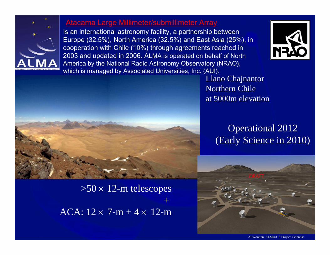
Atacama Large Millimeter/submillimeter ArrayIs an international astronomy facility, a partnership between Europe (32.5%), North America (32.5%) and East Asia (25%), in cooperation with Chile (10%) through agreements reached in 2003 and updated in 2006. ALMA is operated on behalf of North America by the National Radio Astronomy Observatory (NRAO), which is managed by Associated Universities, Inc. (AUI).
Al Wootten, ALMA/US Project Scientist
>50 × 12-m telescopes+
ACA: 12 × 7-m + 4 × 12-m
Operational 2012 (Early Science in 2010)
Llano Chajnantor Northern Chileat 5000m elevation
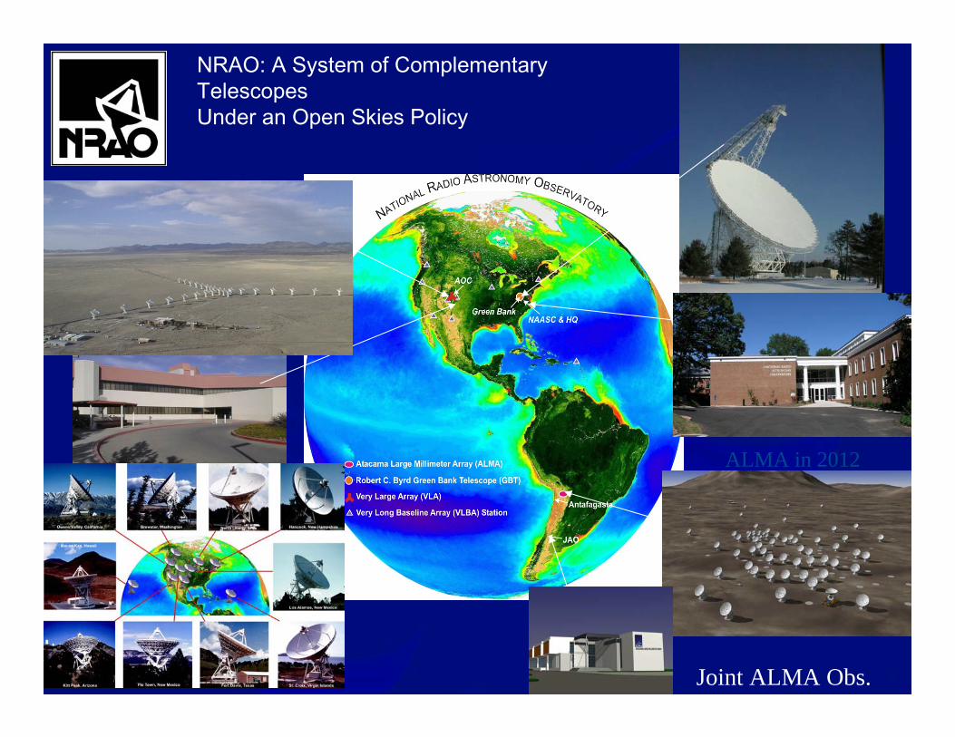
NRAO: A System of Complementary TelescopesUnder an Open Skies Policy
ALMA in 2012
Joint ALMA Obs.
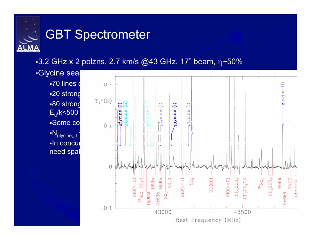
GBT Spectrometer
3.2 GHz x 2 polzns, 2.7 km/s @43 GHz, 17” beam, η~50%Glycine search 42.7-45.6 GHz in Irc-2: 100 lines T>10mK
70 lines of known molecules, ions20 strong lines of unknown molecules80 strong glycine lines (2/3 conformer I, 1/3 conformer 2) with s>1,
Eu/k<500 cm-1
Some coincidences, but many expected lines absentNglycine,, I < 1.5 x 1014 cm -2 (∆V 4 km/s, Trot=100K)In concurrent observations with the PdBI, some confusion is removed;
need spatial resolution and sensitivity of ALMA.

Sept 2006: First Light &engineering observations
Dec 2007: commissioning, earlyscience
Fall 2008: GBT surface 10%->30%Winter 08/09: Shared Risk ObservingFall 2009: Proposable Facility Instrument

ALMA Science Requirements
Three “level I” science goals:
Spectral line CO/C+ in z=3 MWG < 24hrsresolve PPD at 150 pc –gas/dust/fieldsPrecise 0.1” imaging above 0.1% peak
High Fidelity Imaging. Routine sub-mJy Continuum / mK Spectral Sensitivity.Wideband Frequency Coverage.Wide Field Imaging Mosaicing.Submillimeter Receiver System (..& site..).Full Polarization Capability.System Flexibility (hardware/software).

Technical Specifications>54 12-m antennas, 12 7-m antennas, at 5000 m altitude site.Surface accuracy ±25 µm, 0.6” reference pointing in 9m/s wind, 2” absolute pointing all-sky.Array configurations between 150m to ~15 -18km.10 bands in 31-950 GHz + 183 GHz WVR. Initially:84-116 GHz “3”125-169 GHz “4”163-211 GHz “5” 6 rx only, single polzn211-275 GHz “6”275-373 GHz “7”385-500 GHz “8”602-720 GHz “9”787-950 GHz “10” initially partially populated8 GHz BW, dual polarization.Flux sensitivity 0.2 mJy in 1 min at 345 GHz (median cond.).Interferometry, mosaicing & total-power observing.Correlator: 4096 channels/IF (multi-IF), full Stokes.Data rate: 6MB/s average; peak 60 MB/s. All data archived (raw + images), pipeline processing.

Specifications Breed Transformational Performance
• With these specification, ALMA improves• Existing sensitivity, by about two orders of magnitude
• Best accessible site on Earth• Highest performance receivers available• Enormous collecting area
• Resolution, by nearly two orders of magnitude• Not only is the site high and dry but it is big! 18km
baselines or longer may be accommodated.• Wavelength Coverage, by a factor of two or more
• Take advantage of the site by covering all atmospheric windows with >50% transmission above 30 GHz
• Bandwidth, by a factor of a few• Correlator process 16 GHz or 8 GHz times two
polarizations• The discovery parameter space is greatly expanded!

ALMA Polarization Requirements
General Science Requirements for PolarizationFrom ALMA-09.00.00.00-001-A-SPE:
•It shall be possible to measure all polarization cross products simultaneously.•For an unpolarized source, the percent error in polarized flux should be less than 0.1% of the total intensity after calibration.•It shall be possible to measure the position angle to within 6 degrees.•The differential gain stability between the two polarization channels must be better than 10-3 in 5 minutes (typical timescale between polarization calibration observations).•ALMA shall maximize sensitivity over its frequency bands.•Meeting the polarization requirements is particularly important for band 7 and could require a quarter-wave plate.•Question: Do the designs meet these requirements and do the as-built receivers meet them?

ALMA – Major Elements
Partners: US (NSF/NRAO)+Canada (NRC) – ESO Chile – Japan (NINS)+Taiwan (ASIAA)
Action SitesArray Operations Site – AOS 5000mOperations Support Facility – OSF 2900mSantiago Central Offices – SCOALMA Regional Centers – ARCs + ARC nodesALMA Test Facility--Near Very Large Array, NM
During full operation, the estimated flow into archive ~ 100 Tbytes per yearDataset: proposal, u-v data, a reference image with pipeline processing history, calibration data… modern radioastronomyWhere are we in the construction phase?
Photo H. Heyer (ESO).
Eight antennas now in Chile

How can I find the ALMA Site?
Santiago
Paranal
La Serena

Where is ALMA?

Array Operations Site: 16400 feet43 km from gate on CH23 on 51ft wide new road
Array Operations Site Technical Building
•Array reconfigurable 150m-14km•Digitized signals from antenna to TB
•TB houses Correlator•Local oscillator signals•Antenna transporter shelter•Refuge•No one overnight, few during day

Operations Support Facility: 9500 ft altitude15 km from gate on CH23
•Technical Building•Completed•Warehouse•Shops, offices, antenna area
•Camps: House, feed and amuse >500 people
•ALMA•Contractors
•Antenna erection areas•VertexRSI (NA)•Mitsubishi (JP)•Alcatel (EU)
•Temporary OfficesOSF TB

ALMA and Contractor Camps
View to the ALMA Camp
•ALMA Camp•Housing•Offices•Dining Hall•Recreation Hall•Tennis court•Temporary technical building
•Future: Residence

ALMA and Contractor Camps
View to the Contractor Camp
•Contractors Camp•Housing•Offices•Dining Hall•Recreation Hall

Antenna Vendor Areas
View of AEM, MElCo, VxRSI areas (l-r)
Four Melcos;
VxRSI No 1
Holographic surface measurements onMElCo No 1 confirm night stable @14 µm!
VxRSI No 2 and 3

Antenna Locomotion: Transporters
10 meters wide, 20 meters long and 6 meters high,Now rolling around at the OSF site.Sorry applications for transporter driver are

ALMA Test Facility, New Mexico
Fringes using ALMA prototype system Mar ‘07Test ALMA software and most hardware prior to installation in Chile late summer ‘08.Production ‘Front Ends’ bypass ATF, first is en route to Chile right now.

Transparent Site Allows Complete Spectral Coverage
10 Frequency bands coincident with atmospheric windows have been defined.
Bands 3 (3mm), 6 (1mm), 7 (.85mm) and 9 (.45mm) will be available from the start.
Bands 4 (2mm), 8 (.65mm) and, later, some 10 (.35mm), built by Japan, also available.
Some Band 5 (1.5mm) receivers built with EU funding.
All process 16 GHz of data2polzns x 8 GHz (1.3mm=B6)2 polzns x 2SBs x 4 GHz
(3mm=B3, 2mm=B4, .8mm=B7, .6mm=B8, 1.5mm=B5)
2 polzns x DSB x 8 GHz (.45mm=B9, .35mm=B10)

ALMA Receivers/Front Ends
• Dual, linear polarization channels:•Increased sensitivity•Measurement of 4 Stokes parameters
•183 GHz water vapour radiometer:•Used for atmospheric path length correction
NAOJ ?
SRON
NAOJ
IRAM
NRAO
6 units EU ?
NAOJ
HIA
Not assigned
Not assigned
Responsible
SIS
SIS
SIS
SIS
SIS
SIS
SIS
SIS
HEMT
HEMT
Receiver technology
787 – 950 GHz
602 – 720 GHz
385 – 500 GHz
275 – 373 GHz*
211 – 275 GHz
163 - 211 GHz
125 – 169 GHz
84 – 116 GHz
67 – 90 GHz
31.3 – 45 GHz
Frequency Range
DSB345 K230 K10
DSB263 K (150K)175 K (120K)9
2SB147 K98 K8
2SB221 K (90K)147 K (80K)7
2SB138 K (60K)83 K (40K)6
2SB108 K65 K5
2SB85 K51 K4
2SB62 K (50K)37 K (35K)3
LSB50 K30 K2
USB28 K17 K1
Mixing schemeTRx at any RF
frequencyTRx over 80% of
the RF band
Receiver noise temperatureALMABand

Passband taken with ALMA Band 6 mixer at the SMT
Ziurys has shown a SgrB2(N) spectrum at the American Chemical Society meeting in Atlanta, obtained with an ALMA prepreproduction B6 front end on the SMT. This system achieved 107 K system temperature, SSB at 45 deg. elevation at 232 GHz, with > 20 db image rejection, good baselines.

Baseline Correlator Overview
Observer may specify a set of disjoint or overlapping spectral regions, each characterized by
Bandwidth (31.25 MHz to 2 GHz)Each 2 GHz baseband input (8 available) drives 32 tunable digital
filtersFrequency (Central or starting)Resolution (number of spectral points)Number of polarization products: 1 (XX or YY), 2 (XX and YY) or 4 (XX, YY,
XY, YX cross-polarization products)Improved sensitivity options (4x4 bit correlation, or double Nyquist modes)Temporal resolution depends upon mode (from 16 msec to 512 msec);
1msec autocorrelationSimultaneous pseudo-continuum and spectral line operation

Summary of current status
30 to 0.016” at 300 GHz: Configuration definedAngular resolution
0.2 mJy in 1 min at 345 GHz (median conditions)Flux sensitivity
Up to 64 antennas of 12m diameter, plus compact array of 4 x 12m and 12 x 7m antennas (Japan): Contracts for 55 up to 67, three prototype antennas in hand meet all
Antenna complement
10000:1 (spectral); 50000:1 (imaging)Dynamic range
31.5 kHz (0.01 km/s) at 100 GHz: 1st quadrant built
Spectral resolution
8 GHz both polzns, fully tunable: All unitsBandwidth
30 to 950 GHz: B3, B6, B7, B9 receivers passed CDR & PAI, preproduction units available, all meet Trx spec, most exceed specs. B6 tested on SMT.
Frequency

Receiver Status: Polarization
Approach: •All receivers detect linear polarization•Design to achieve specifications•Complete electromagnetic analysis of design (including antenna, subreflector, receiver) to identify problem areas•Build Eight Pre-Production units to test•Proceed with Production contract for remaining 62 units.
Status•Electromagnetic Analysis complete•Most Pre-Production cartridges complete•First complete Front End en route to Chile•Contracts for high frequency receivers signed

Polarization Issues: Band 3 (3mm)
B3 (3mm): Both EM analysis and lab tests suggest horn redesign would improve performance near 115 GHz; under way.
Built at HIA, Victoria, CanadaWarm lens at cryostat

Band 6 (1.3mm)
B6 (1.3mm): EM analysis suggested excellent design; lab tests uncovered OMT irregularities in early units, now amended so that lab performance meets EM analysis predictions.
Built at NRAO NTCHighest frequency band in which an ortho-mode transducer is used

Band 7 (0.87 mm)
B7 (.87mm):EM analysis suggested IR filter reflections
decrease cross-pol performance to ~-18dB. Filter modification under way
Measurement identifies a second problem, remedy under consideration involves twist in waveguide (so some early cartridges will be rotated 37.5º)
Built at IRAMPolarization separation achieved by wire grid

Band 9 (0.45 mm)
Some cross-polarization leakage owing to grids; remedy under investigation
Built at SRON, Netherlands.Double sideband performance; wire grid separates polarizations

Full Polarization Correlator Modes

ALMA Design Reference Science Plan(DRSP)
Goal: To provide a prototype suite of high-priority ALMA projects that could be carried out in ~3 yr of full ALMA operations
DRSP 1.0 finished December 2003; >128 submissions received involving >75
astronomersReview by ASAC members completed; comments
included(DRSP2.0) updated to include enhancements brought
to project by Japan/East Asia. Reviewed by Science Advisory Committees Current version of DRSP on Website at:http://www.strw.leidenuniv.nl/~alma/drsp.html
New submissions continue to be added.

DRSP 2.2.2 Magnetic field geometry in protostellar envelopes Author: J Richer
Science goal: Make images of linearly polarised dust emission in the envelopes of protostars to constrain role of magnetic fields in star formation.In the inner parts (<1000 AU) of the envelope one expects emission at the level of about tens of mK and stronger (using a simple 1/r^2 isothermal envelope model). Thus one can detect few % polarisation at the several sigma level, which is just about good enough. This is very model

Choose Polzn Science: DRSP 2.2.2
Receiver Band: 7 (870 micron)Lines: CO(3-2) CN(J=3-2), 13CO(J=3-2), C18O(J=3-2)
Freq (GHz): 345.796 340.248 330.588 329.33054
Cannot get them all; scratch COSpectral Resolution (km/s): 0.1 km/s Spatial: 1”Spectral Coverage (km/s): 150-200 km/s/lineMode 16: 0.16 km/s resolution for CN lines 250 MHz totalMode 36: 0.08 km/s; 2048 channels 62.5 MHz totalScience goals: Continuum polarizationContinuum RMS: 130µK 0.013 mJy/beam Line RMS per 0.1 km/s channel: 0.006K
Integration time per setting: 4 sources x 7 pointings per source x 240 minutes per pointing

Brightness Temperature Sensitivity1 min, AM 1.3, 1.5mm, *0.35 PWV, 1 km/s
Frequency(GHz)
Bmax 0.2km∆Tcont (K)
Bmax 0.2km∆Tline (K)
Bmax 10km∆Tcont (K)
Bmax 10km∆Tline (K)
35 0.002 0.050 0.48 130
110 0.003 0.049 0.84 120
230 0.0005 0.054 1.3 140
345 0.0014 0.12 3.6 300
409 0.0030 0.23 7.6 580
675* 0.0046 0.28 12 690
850* 0.011 0.58 27 1400
1500* 1.4 57 3600 140000For ν<430 GHz, PWV=1.5mm; ν >430 GHz, PWV=0.35mm

www.alma.info
The Atacama Large Millimeter/submillimeter Array (ALMA), an international astronomy facility, is a partnership among Europe, Japan and North America, in cooperation with the Republic of Chile. ALMA is funded in Europe by the European Organization for AstronomicalResearch in the Southern Hemisphere, in Japan by the National Institutes of Natural Sciences (NINS) in cooperation with the Academia Sinica in Taiwan and in North America by the U.S. National Science Foundation (NSF) in cooperation with the National Research Council of Canada (NRC). ALMA construction and operations are led on behalf of Europe by ESO, on behalf of Japan by the National Astronomical Observatory of Japan (NAOJ) and on behalf of North America by the National Radio Astronomy Observatory (NRAO), which is managed by Associated Universities, Inc. (AUI).