all-metal joints studies related to the mechanical and irradiation przemyslaw lutkiewicz...
TRANSCRIPT

All-metal joints studies related to the mechanical and irradiation
Przemyslaw LutkiewiczSupervisors:
Christian Rathjen, CERNCedric Garion, CERNBlazej Skoczen, CUT

Answer the question How leak-tightness is made How all-metal joints behave How irradiation and inelastic deformation influence on
joint behavior (CDM theory extension) Understand the material and geometrical influences on the
sealing properties Develop tools and methods helpful in the joint design process Apply that knowledge to the new design
“All metal joints studies related to the mechanical and irradiation load”
Thesis scope
Przemyslaw Lutkiewicz AT/VAC

ConFlat jo int studies (about 4600 units for LH C)
new jo int design for CLIC (about 460000 units)
Continuum D am age M echanic theory approach M echanical load (a lready
w ell know n) Irradiation (m y scientific
input )
ConFlat joint studies (about 4600 units for LHC)
new joint design for CLIC (about 460000 units)
Continuum Damage Mechanic theory approach Mechanical load (already
well known) Irradiation (my scientific
input )
PhD thesis subject:
ConFlat joint
Przemyslaw Lutkiewicz AT/VAC
CLIC joint pa
rticl
e be
am fl
ow
material under mechanical load and radiation
Mechanical load

1. ConFlat joint studies
Joint consists of:1. “soft” gasket (OFS Cu)2. “hard” flanges with knives (SS 316LN)3. bolts, clamps or chains
ConFlat join setup
ConFlat joint concept
Bolts push the “hard” flange knifes into “soft” gasket
A high contact pressure acts between the knife and gasket surfaces
Plastic flow occurs in the gasket
Gasket material fills gaps and makes joint leak tight
1.
2.
3.
Przemyslaw Lutkiewicz AT/VAC
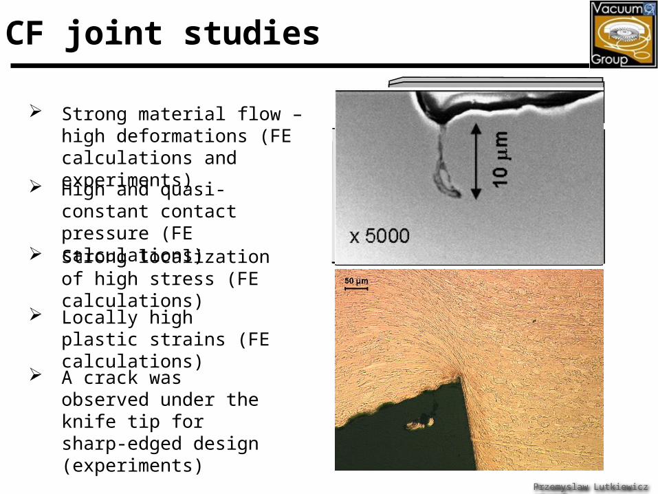
1. CF joint studies
Strong material flow – high deformations (FE calculations and experiments)
High and quasi-constant contact pressure (FE calculations)
Strong localization of high stress (FE calculations)
Locally high plastic strains (FE calculations)
A crack was observed under the knife tip for sharp-edged design (experiments)
Przemyslaw Lutkiewicz AT/VAC

Przemyslaw Lutkiewicz AT/VAC ; [email protected]
Experimental Material properties definition
Damage tensor results for anisotropic material
Damage tensor results for isotropic material
Proceeding with the publication
CF joint anisotropic damage analysis
Fig. 9. Anisotropic model: a; Distribution of micro-damage (D11, D22, and D33) compared to evolution of plastic strain intensity (EPSE), b;
Evolution of micro-damage components as a function of depth
Fig. 4. Damage parameter D and elastic unloading modulus E as a function of strain at 4.2 K
1. CF joint studies

1. CF joint studies
Two stage behavior Stage I – “elastic” Stage II – “plastic”
Two stage behavior compares well with bilinear gasket material model
Good correlation between experiments and FEM
Sealing force evolution
Przemyslaw Lutkiewicz AT/VAC
FE calculations experiments

1. CF joint studies – material influences
Sealing force evolution
Material properties strongly influence the joint behavior
Results were obtained using Finite Element modeling (ANSYS)
Based on those results the phenomenological formula was defined (2008, JVST A): Describes evolution of
displacement with force Depends on elastic-
plastic gasket material properties E , 0, H
Przemyslaw Lutkiewicz AT/VAC

1. CF joint studies – experiments
Przemyslaw Lutkiewicz AT/VAC
Locating pins
Experiment setup

1. CF joint studies – experiments
Leak rate evolution Tightness during compression
Przemyslaw Lutkiewicz AT/VAC
Compression tests

1. CF joint studies – resume
Different material properties for gasket material in different directions (anisotropy)
High plastic strain concentration indicate macro crack propagation possibility
Tightness is done on the lower “knife” slope, second “knife” slope is not at the contact with the gasket
Joint behavior is related strictly to elastic-plastic gasket material properties and can be described by phenomenological function
Joint is leak tight when gasket is plastifed through the thickness
ConFlat joint is leak tight for about 0.1-0.15 mm imprint
Przemyslaw Lutkiewicz AT/VAC

Przemyslaw Lutkiewicz AT/VAC ; [email protected]
1. Reliable joint - high sealing performance
2. No plastic deformations on flanges
3. Smooth flange-gasket-flange transition ( no gaps)
4. Simple shapes and preferably symmetrical joint
type
5. Easy in assembly
6. Cheep in production and low sensitivity on
machining tolerances
2. CLIC joint

Przemyslaw Lutkiewicz AT/VAC ; [email protected]
SLAC X-band joint Stainless steal WR90 flange
(male and female type) 31.9 x 19.2 mm copper
gasket, 4.42 mm width and 2.03 mm high
CLIC gasket vs 2 CHF coin
Joint conceptDrawbacks (things to be improved): Large and non constant
displacements into gasket aperture (0.25 mm = ¼ of the gasket thickness)
Different contact pressure distribution for upper and lower surface of the gasket
Trapped volume and grove weakness
0.25
0.25Lateral profile of the maximum inner displacementsContact pressure between upper gasket surface and flange
Contact pressure between lower gasket surface and flange
No sealing
Sealing
No sealing
Sealing
Upper surface
Contact pressure between upper gasket surface and flange
No sealing
SealingTrapped volume
Contact pressure near grove
No sealingSealingNo sealing
No sealingSealingSealing
2. CLIC joint

Rectangular in cross-section OFS copper gasket
Symmetrical, “knife” based design Conical side – higher slope Flat side – possible low slop
Initial gasket position back from flange-flange aperture face
SS 316LN flanges with 8 screws and two locating pins
Symmetry
Existing design concept
Przemyslaw Lutkiewicz AT/VAC
gasket
flange
gasket
flange
flange
New CLIC design concept
2. CLIC joint

Homogeneous contact pressure – the joint is symmetric type (sexless)
Homogeneous contact pressure – the joint is symmetric type (sexless)
Przemyslaw Lutkiewicz AT/VAC ; [email protected]
Cheaper production – simple and easy to machine gasket shape and one type of flange
Easier assembly – symmetric, self-placed gasket with additional pins centering joint system
Superior RF properties – smooth flange-gasket-flange transition
SYMMETRYNO SYMMETRY
New proposalOld design
2)
3)
1)
1)
1)
2)
1) Female flange2) Gasket with moderate shape3) Male flange
1) One type of flange2) Gasket with simple shape
self-placed gasket self-placed
gasket +
Pins centeringjoint system
0.25 mm
0.15 mm
Flange
Flange
Gasket
> 0.1 mm
Flange
Flange
Gasket
2. CLIC joint

Przemyslaw Lutkiewicz AT/VAC
R
P
w
AQ 306.0exp3400
2
21
111
QQQT
Theoretical leak rate
Total leak rate
Collar interaction
Thickness [mm]
Imprint depth [mm]
Alpha [deg]
Beta [deg]
Initial position
[mm]
Initial values Yes 2.0 0.3 30 5 -0.35
Final values No 2.5 0.3 35 5 -0.1
Alpha (Q1)Beta (Q2)
Gasket thickness
Initial position
2. CLIC joint

1.25 1.5 1.75 2 2.25 2.5 2.75 3 3.25 3.5 3.751.0E-16
1.0E-15
1.0E-14
1.0E-13
1.0E-12
1.0E-11
1.0E-10
1.0E-09
1.0E-08
Gasket thickness [mm]
Leak
rate
[mba
r l/s
]
Przemyslaw Lutkiewicz AT/VAC
Q1
Q2 collar interaction
no collar interaction
2. CLIC joint

The displacement into aperture as an input for future RF calculations
Przemyslaw Lutkiewicz AT/VAC
Displacement into the aperture
2. CLIC joint

Przemyslaw Lutkiewicz AT/VAC
Pressure distribution through the gasket circumferance
2. CLIC joint

Przemyslaw Lutkiewicz AT/VAC ; [email protected]
The leak tightness test: Reference joint parameters:
1.4e-10 mbars L/ s ~60% to 100% of clumping disp. Confirmed 4 times
Finally defined joint parameters 5.6e-11 mbars L/s ~60-115% of clumping disp. Confirmed 3 times
The leak tightness level
Joint at the experiment
Displacement into aperture: Reference joint parameters:
0.08 mm @ 0.30 mm Flange’s knifes plastically deformed
Finally defined joint parameters 0.031mm @ 0.33 mm Flange - no plastic deformation
2. CLIC joint

Irradiation types:
Light charged radiation• Beta particles• Electrons
heavy charged radiation• Ions• Alfa• Protons
Light neutral radiation• Photons (Gamma/X-ray)
Heavy neutral radiation• Neutrons
3. New CDM theory (irradiation)
Irradiation effects:
Impurity production Ionization Heating Atom displacements – defects
creation
Przemyslaw Lutkiewicz AT/VAC

The irradiation level [dpa] can be calculate in two ways:
From NIEL using Norgett-Robinson-Torrens equation
NIEL from Monte Carlo codes like FLUKA, SRIM
Non Ionizing Energy Loss profile
dNRT
E
NIELN
2
8.0
V
Ndpa
at
NRT
2216.1~1cm
nEdpa
Przemyslaw Lutkiewicz AT/VAC
3. New CDM theory (irradiation)

The irradiation level suspect at LHC project at most critical region (near the collimators)
If the all NIEL energy is consider to contribute into dpa production -> ~8 dpa
First calculations with FLUKA code -> 1e-4 up to 1e-3 dpa
Results based on the neutron flux value -> 8e-4
FLUKA calculations with the synchrotron light contribution -> ??? [dpa]
Przemyslaw Lutkiewicz AT/VAC
1 MeV neutron equivalent flow.
3. New CDM theory (irradiation)

Irradiation effects:
Yield point increasing
Uniform elongation decreasing
Plastic flow instability
Tensile tests results for different irradiation dose [dpa]
Przemyslaw Lutkiewicz AT/VAC
3. New CDM theory (irradiation)

NdGbMH Ty
Orowan mechanism
Yield point increasing, irradiation hardening H
Przemyslaw Lutkiewicz AT/VAC
Irradiation defects
Hardening as a [dpa] dose function
3. New CDM theory (irradiation)
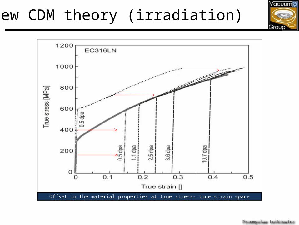
Offset in the material properties at true stress- true strain space
Przemyslaw Lutkiewicz AT/VAC
3. New CDM theory (irradiation)

Representative Volume Element
As
YpD ,~ s
D
A
AD
Damage parameter definition
where
D
1~
)1(~
DEE
crDDfor
Damage influences
Effective stress
Effective Elastic modulus
Macro - Crack propagation
Mechanical load
AD
Elastic modules changes for OFS copper
Przemyslaw Lutkiewicz AT/VAC
3. New CDM theory (irradiation)

parti
cle
beam
flow
material under mechanical load and radiation
Mechanical load
Przemyslaw Lutkiewicz AT/VAC
3. New CDM theory (irradiation)
Irradiation influence on the material structure

SRIM calculation (Monte-Carlo method)
micro-voids cluster formation
Micro-voids cluster
Przemyslaw Lutkiewicz AT/VAC
3. New CDM theory (irradiation)
Classical damage evolution
Irradiation damage – cluster nucleation and growth made by irradiation
Post-irradiation damage – cluster growth made by mechanical load
The assumption is made that:
)(dpafDr
,,, pDdpaDYpDD rrm
D
s
ppHpS
YD
eq
m
r
r pD
D
2
3exp57.0

Przemyslaw Lutkiewicz AT/VAC
Mechanical damage for irradiated CF gasket
Post-irradiation damage for irradiated CF gasket
Results pure mechanical
damage – 0.48 Irradiation damage
– 0.06 Post-irradiation
damage - 0.19
3. New CDM theory (irradiation)

Przemyslaw Lutkiewicz AT/VAC
Damage results pure mechanical
load is weakly influenced by irradiation
Irradiation damage is critical around and over cluster saturation [dpa] value
Post-irradiation damage can be about two times higher than initial irradiation ones
Post-irradiation damage evolution for different [dpa] values
3. New CDM theory (irradiation)

Przemyslaw Lutkiewicz AT/VAC
Post irradiation damage evolution theories:
Based on the cluster diameter growth mechanism [1,2]
Based on the damage parameter evolution [3,4]
Results differences for different approaches
3. New CDM theory (irradiation)

Different irradiation types can be unified by [dpa]
Even small [dpa] dose influence on the material properties strongly (change the components mechanical behavior)
Radiation increase the elastic limit (good) but also make the material more brittle (bad)
Radiation and plastic deformation are the source of micro-voids (decrease the mechanical properties and can be filled with gas – source of virtual leak)
Irradiation and post irradiation damage contribution is critical for around and over the saturation [dpa] value
Przemyslaw Lutkiewicz AT/VAC
3. New CDM theory (irradiation)

With width like old design
With width like 1/3 of old design THE END
Thanks for Your attention
Przemyslaw Lutkiewicz AT/VAC