all bands, all technologies, simultaneously, future-proof
TRANSCRIPT
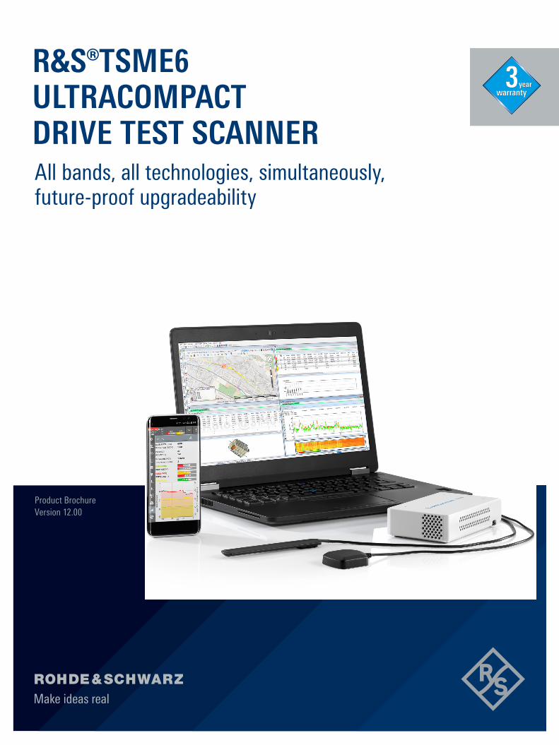
Product Brochure Version 12.00
All bands, all technologies, simultaneously, future-proof upgradeability
R&S®TSME6 ULTRACOMPACT DRIVE TEST SCANNER
year
2
AT A GLANCEThe R&S®TSME6 is designed for efficient drive and walk tests with a maximum degree of freedom and upgradeability. With its ultracompact design and multiband and multitechnology support for simultaneous measurements, the scanner fulfills all requirements for a state-of-the-art measurement tool.
With its ultrabroadband frontend, the scanner measures all supported technologies from 350 MHz to 6 GHz simultaneously. The futureproof architecture and infield upgradeability for both hardware and software allow up to 4x4 MIMO measurements and pave the way for 5G.
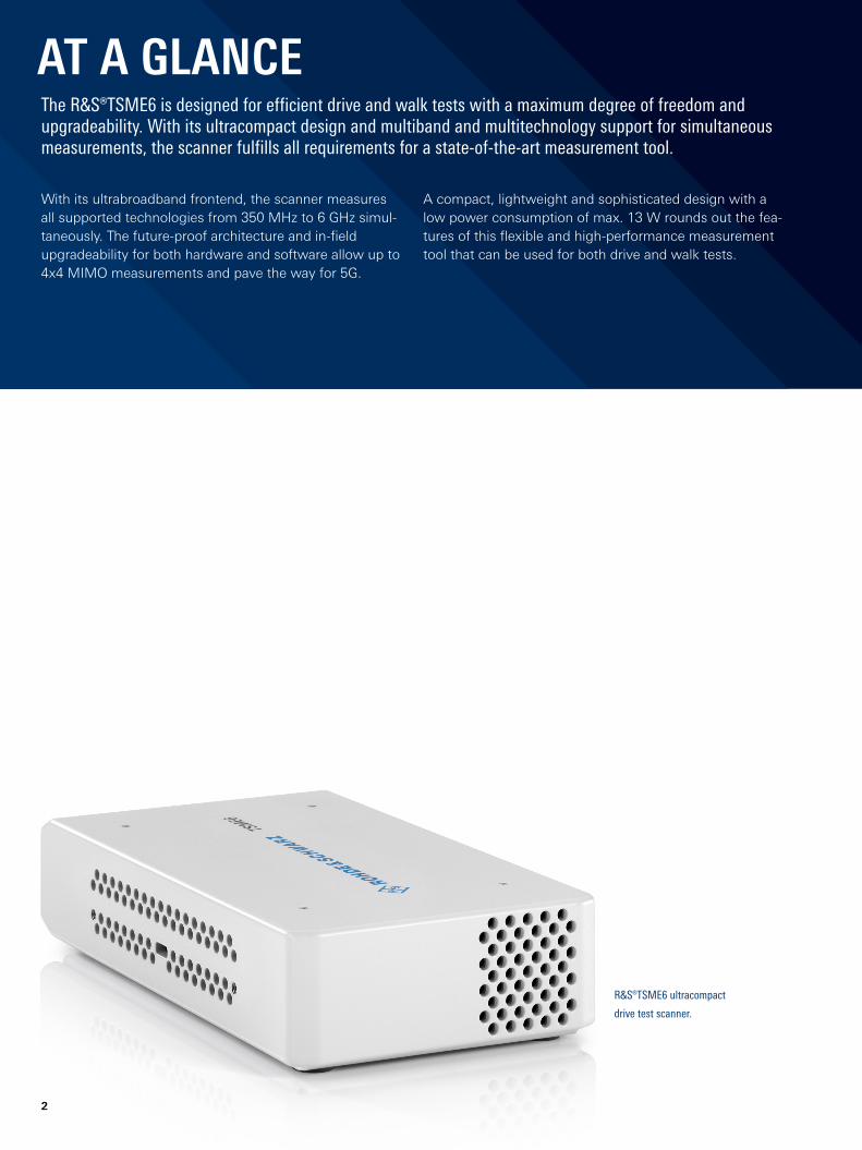
R&S®TSME6 ultracompact
drive test scanner.
A compact, lightweight and sophisticated design with a low power consumption of max. 13 W rounds out the features of this flexible and highperformance measurement tool that can be used for both drive and walk tests.
Rohde & Schwarz R&S®TSME6 Ultracompact Drive Test Scanner 3
BENEFITSMaximum diversity for 3GPP bands and technologies with future-proof architecture
► Simultaneous measurements with no limitations in 3GPP frequency bands and technologies with SIB/L3 decoding support
► Cascading and upward/downward compatibility for a maximum degree of freedom
► Easy software and hardware upgrades for new features ► Proof of upgradeability: mmWave and sub6 GHz 5G NR measurements on the R&S®TSME6
► page 4
Supported by a wide variety of software products ► Universal software platform for parallel measurements with scanners and test UEs for QoS and user experience analysis
► Advanced measurements in LTE for troubleshooting and optimization
► Scanner application in benchmarking and optimization solutions
► Open interface and use as OEM ► page 8
Backpack system ► Maximum independence and configuration freedom
► Rugged and lightweight for all types of measurement campaigns
► page 11
Versatile design and functionality ► Ultracompact design ► Minimal noise through advanced cooling concept and low power consumption
► Integrated multiGNSS with improved sensitivity and untethered dead reckoning
► Reduced setup time to increase efficiency of drive and walk tests
► NBIoT/Cat NB1 measurements ► LTEM measurements ► RF power spectrum measurements up to 6 GHz for spectrum clearance
► Advanced measurements for deep network insights
► page 9
KEY FACTS ► No limitations in 3GPP frequency bands up to 6 GHz
► More than ten technologies simultaneously in one scanner
► Supports R&S®TSME30DC and R&S®TSME44DC downconverters for mmWave measurements
► Compact and lightweight design with customized mechanical concept for cascading
► Low power consumption
4
MAXIMUM DIVERSITY FOR 3GPP BANDS AND TECHNOLOGIES WITH FUTURE-PROOF ARCHITECTURESimultaneous measurements with no limitations in 3GPP frequency bands and technologies with SIB/L3 decoding supportThe core of the R&S®TSME6 consists of very fast signal processing and a receiver frontend that supports the frequency range from 350 MHz to 6 GHz without any gaps. Decades of Rohde & Schwarz RF experience allows both to be combined in an extremely compact scanner. The R&S®TSME6 is fully user configurable and features simultaneous measurements. It covers all major wireless communications standards and offers deep RF and network insights with SIB/layer 3 decoding support and advanced measurements in LTE.
With well established LTEAdvanced network features such as carrier aggregation, it is designed for high measurement speeds, even in a multicarrier, multitechnology configuration.
Multitechnology measurements are mandatory for 5G NR nonstandalone networks. Since information necessary to access the 5G NR carrier is transmitted on LTE, the R&S®TSME6 is able to decode the latest Rel. 15 SIB messages for LTE5G NR dual connectivity and to perform these measurements simultaneously at high speed.
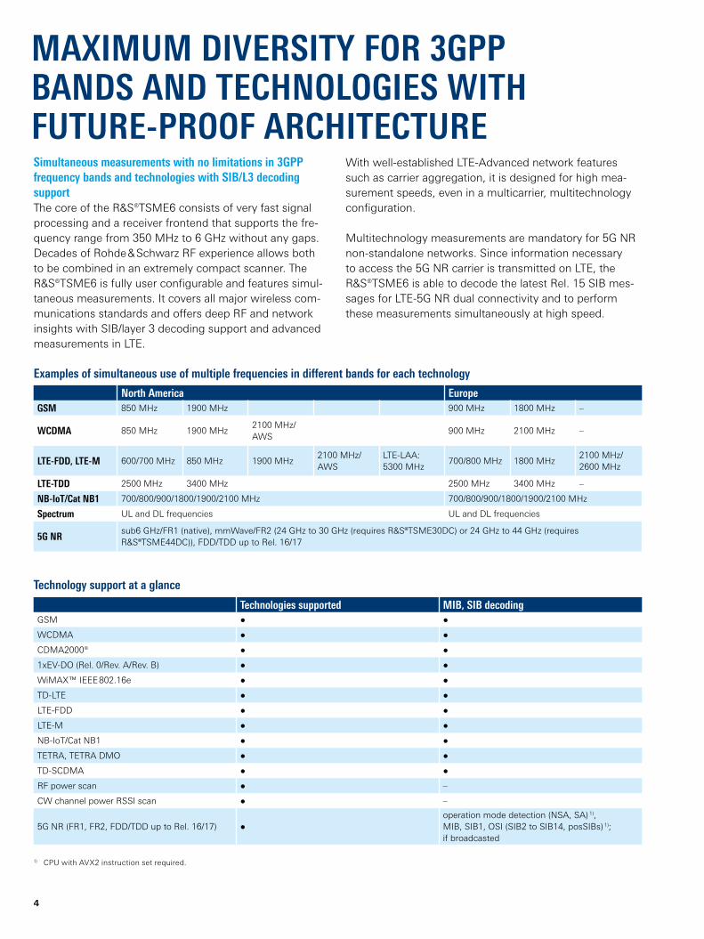
North America EuropeGSM 850 MHz 1900 MHz 900 MHz 1800 MHz –
WCDMA 850 MHz 1900 MHz2100 MHz/AWS
900 MHz 2100 MHz –
LTE-FDD, LTE-M 600/700 MHz 850 MHz 1900 MHz2100 MHz/AWS
LTELAA: 5300 MHz
700/800 MHz 1800 MHz2100 MHz/ 2600 MHz
LTE-TDD 2500 MHz 3400 MHz 2500 MHz 3400 MHz –
NB-IoT/Cat NB1 700/800/900/1800/1900/2100 MHz 700/800/900/1800/1900/2100 MHz
Spectrum UL and DL frequencies UL and DL frequencies
5G NRsub6 GHz/FR1 (native), mmWave/FR2 (24 GHz to 30 GHz (requires R&S®TSME30DC) or 24 GHz to 44 GHz (requires R&S®TSME44DC)), FDD/TDD up to Rel. 16/17
Technologies supported MIB, SIB decodingGSM ● ●
WCDMA ● ●
CDMA2000® ● ●
1xEVDO (Rel. 0/Rev. A/Rev. B) ● ●
WiMAX™ IEEE 802.16e ● ●
TDLTE ● ●
LTEFDD ● ●
LTEM ● ●
NBIoT/Cat NB1 ● ●
TETRA, TETRA DMO ● ●
TDSCDMA ● ●
RF power scan ● –
CW channel power RSSI scan ● –
5G NR (FR1, FR2, FDD/TDD up to Rel. 16/17) ●operation mode detection (NSA, SA) 1), MIB, SIB1, OSI (SIB2 to SIB14, posSIBs) 1); if broadcasted
1) CPU with AVX2 instruction set required.
Examples of simultaneous use of multiple frequencies in different bands for each technology
Technology support at a glance
Rohde & Schwarz R&S®TSME6 Ultracompact Drive Test Scanner 5
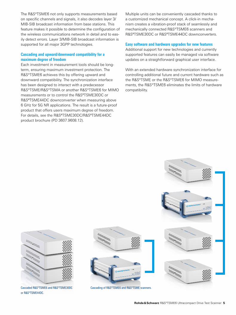
Cascaded R&S®TSME6 and R&S®TSME30DC
or R&S®TSME44DC.
Cascading of R&S®TSME6 and R&S®TSME scanners.
The R&S®TSME6 not only supports measurements based on specific channels and signals, it also decodes layer 3/MIBSIB broadcast information from base stations. This feature makes it possible to determine the configuration of the wireless communications network in detail and to easily detect errors. Layer 3/MIBSIB broadcast information is supported for all major 3GPP technologies.
Cascading and upward/downward compatibility for a maximum degree of freedomEach investment in measurement tools should be longterm, ensuring maximum investment protection. The R&S®TSME6 achieves this by offering upward and downward compatibility. The synchronization interface has been designed to interact with a predecessor R&S®TSME/R&S®TSMA or another R&S®TSME6 for MIMO measurements or to control the R&S®TSME30DC or R&S®TSME44DC downconverter when measuring above 6 GHz for 5G NR applications. The result is a futureproof product that offers users maximum degree of freedom. For details, see the R&S®TSME30DC/R&S®TSME44DC product brochure (PD 3607.9608.12).
Multiple units can be conveniently cascaded thanks to a customized mechanical concept. A clickin mechanism creates a vibrationproof stack of seamlessly and mechanically connected R&S®TSME6 scanners and R&S®TSME30DC or R&S®TSME44DC downconverters.
Easy software and hardware upgrades for new featuresAdditional support for new technologies and currently supported features can easily be managed via software updates on a straightforward graphical user interface.
With an extended hardware synchronization interface for controlling additional future and current hardware such as the R&S®TSME or the R&S®TSME6 for MIMO measurements, the R&S®TSME6 eliminates the limits of hardware compatibility.
6
Proof of upgradeability: mmWave and sub6 GHz 5G NR measurements on the R&S®TSME65G NR is expected to become the leading radio access technology in mobile networks in the next few years. New use cases such as ultra high speed internet access, massive numbers of connected devices and low latency connections require a completely new radio interface compared to LTE. This leads to a very flexible physical layer that can be adapted to different use cases to enhance network availability and maximize quality of service – from low latency to ultra high data rate applications. One example for flexibility is the position of synchronization signal blocks (SSB). SSBs do not necessarily have to be in the center of the 5G NR carrier. It is almost impossible to detect them manually without having detailed information about the network configuration. The automatic channel detection (ACD) feature finds the frequency and transmission case of 5G NR SSBs without any user input except the frequency range where the algorithm should search for 5G NR SSBs.
A special network configuration in the frequency domain is called dynamic spectrum sharing between 5G NR and LTE. It helps operators rapidly deploy 5G NR and use their spectrum even more efficiently. This puts additional requirements on receivers. The R&S®TSME6 is ready to identify and accurately measure such carriers.
Another essential building block of the 5G NR physical layer is the use of beamforming technology. It is the key to overcoming the issue of higher path loss due to operating at higher frequencies. Beamforming is even used for synchronization signals that UEs traditionally use to synchronize with the network. In 5G NR, synchronization signals are also used for channel quality estimations, which are the basis for establishing effective data transmissions.
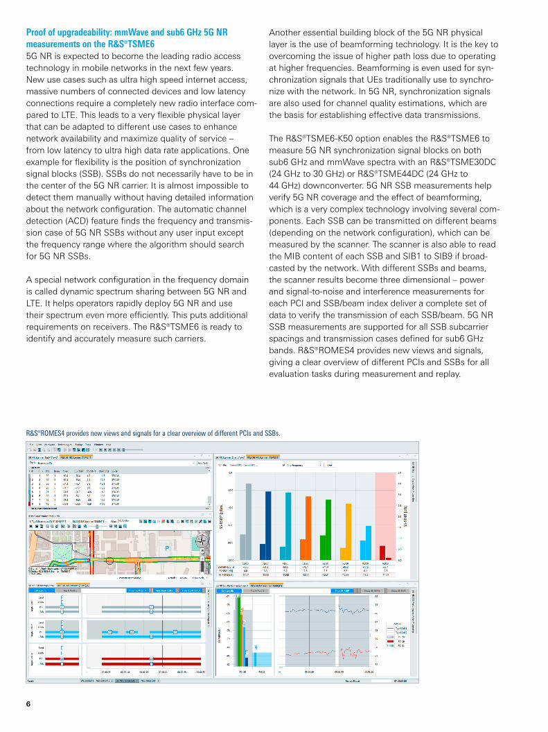
The R&S®TSME6K50 option enables the R&S®TSME6 to measure 5G NR synchronization signal blocks on both sub6 GHz and mmWave spectra with an R&S®TSME30DC (24 GHz to 30 GHz) or R&S®TSME44DC (24 GHz to 44 GHz) downconverter. 5G NR SSB measurements help verify 5G NR coverage and the effect of beamforming, which is a very complex technology involving several components. Each SSB can be transmitted on different beams (depending on the network configuration), which can be measured by the scanner. The scanner is also able to read the MIB content of each SSB and SIB1 to SIB9 if broadcasted by the network. With different SSBs and beams, the scanner results become three dimensional – power and signaltonoise and interference measurements for each PCI and SSB/beam index deliver a complete set of data to verify the transmission of each SSB/beam. 5G NR SSB measurements are supported for all SSB subcarrier spacings and transmission cases defined for sub6 GHz bands. R&S®ROMES4 provides new views and signals, giving a clear overview of different PCIs and SSBs for all evaluation tasks during measurement and replay.
R&S®ROMES4 provides new views and signals for a clear overview of different PCIs and SSBs.
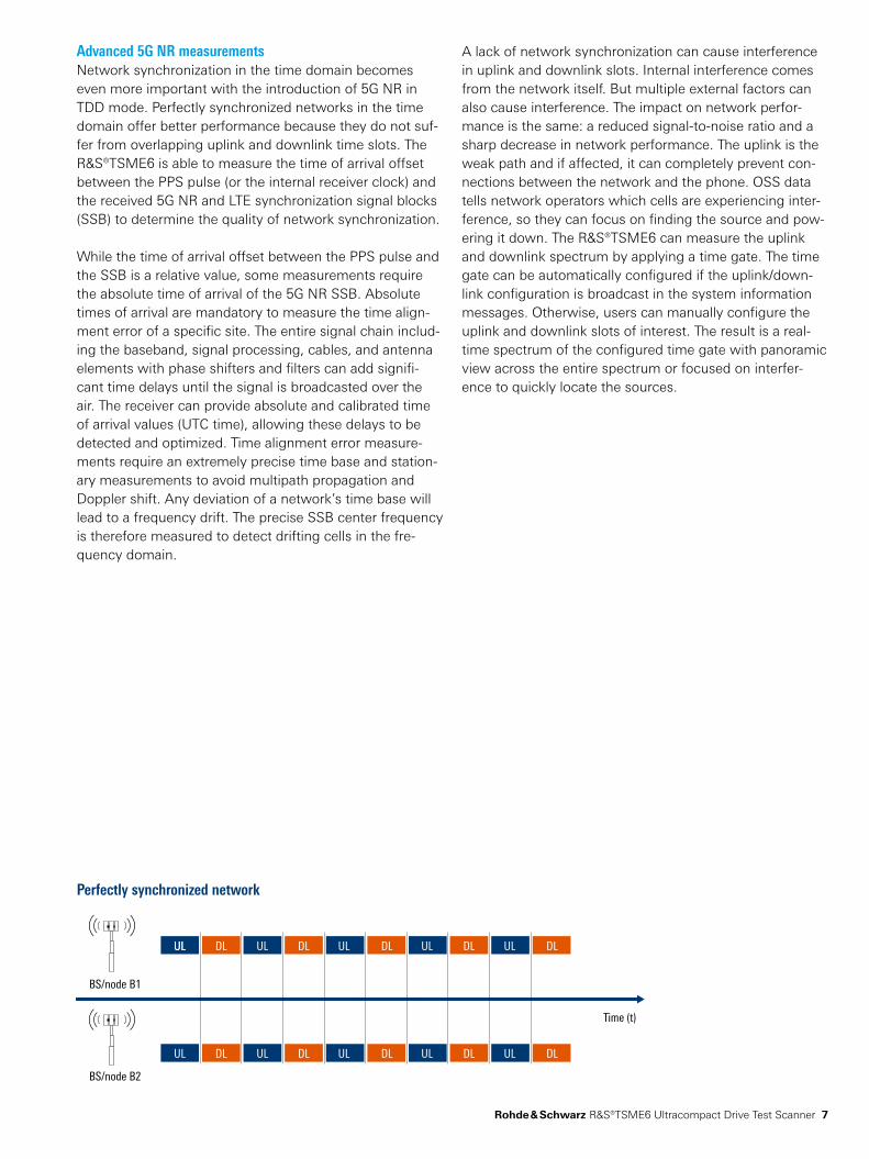
BS/node B1
ULUL DL DL DL DL DLULUL UL UL
UL DL DL DL DL DLULUL UL UL
BS/node B2
Time (t)
Rohde & Schwarz R&S®TSME6 Ultracompact Drive Test Scanner 7
Perfectly synchronized network
Advanced 5G NR measurementsNetwork synchronization in the time domain becomes even more important with the introduction of 5G NR in TDD mode. Perfectly synchronized networks in the time domain offer better performance because they do not suffer from overlapping uplink and downlink time slots. The R&S®TSME6 is able to measure the time of arrival offset between the PPS pulse (or the internal receiver clock) and the received 5G NR and LTE synchronization signal blocks (SSB) to determine the quality of network synchronization.
While the time of arrival offset between the PPS pulse and the SSB is a relative value, some measurements require the absolute time of arrival of the 5G NR SSB. Absolute times of arrival are mandatory to measure the time alignment error of a specific site. The entire signal chain including the baseband, signal processing, cables, and antenna elements with phase shifters and filters can add significant time delays until the signal is broadcasted over the air. The receiver can provide absolute and calibrated time of arrival values (UTC time), allowing these delays to be detected and optimized. Time alignment error measurements require an extremely precise time base and stationary measurements to avoid multipath propagation and Doppler shift. Any deviation of a network’s time base will lead to a frequency drift. The precise SSB center frequency is therefore measured to detect drifting cells in the frequency domain.
A lack of network synchronization can cause interference in uplink and downlink slots. Internal interference comes from the network itself. But multiple external factors can also cause interference. The impact on network performance is the same: a reduced signaltonoise ratio and a sharp decrease in network performance. The uplink is the weak path and if affected, it can completely prevent connections between the network and the phone. OSS data tells network operators which cells are experiencing interference, so they can focus on finding the source and powering it down. The R&S®TSME6 can measure the uplink and downlink spectrum by applying a time gate. The time gate can be automatically configured if the uplink/downlink configuration is broadcast in the system information messages. Otherwise, users can manually configure the uplink and downlink slots of interest. The result is a realtime spectrum of the configured time gate with panoramic view across the entire spectrum or focused on interference to quickly locate the sources.
8
Universal software platform for parallel measurements with scanners and test UEs for QoS and user experience analysisThe R&S®ROMES4 drive test software collects, visualizes and stores data from Rohde & Schwarz scanners and special mobile devices. Both the scanners and mobile devices can be controlled and configured via R&S®ROMES4, which runs through various userconfigurable measurement routines and supports all major 3GPP technologies. Examples of QoS measurements include FTP download/upload and voice quality testing. In combination with special QualiPoc devices, R&S®ROMES4 supports even more test routines, making it possible to analyze the real user experience, for example while a user is uploading a file to a cloud or watching a live video stream.
The package of available test routines, supported technologies and devices is being continually expanded. For example, R&S®ROMES4 supports scanner and device based measurements in 5G NR, NBIoT/Cat NB1 and LTEM networks – the latest network technologies for connecting devices (“things”) to the internet. Both measurements can be performed in parallel, allowing troubleshooting and optimization. As an example, NBIoT devices are limited to one specific network and impaired by different behaviors that are also influenced by the test script. Drive tests conducted with NBIoT user equipment that is actively transferring data miss a certain amount of data during the segments in connected mode. Scanner based measurements are able to supply uninterrupted measurement data independent of the user equipment. They provide the pure RF view needed for verification, troubleshooting, competitor analysis and network optimization.
Advanced measurements in LTE for troubleshooting and optimizationIn the case of unexpected results indicating poor network performance, the parallel scanner measurement can be used to troubleshoot. If the data throughput is lower than expected, the channel quality indicator (CQI) can be used to determine the reason for the reduced data throughput. A low CQI might indicate areas of high interference. High interference reduces the signal to interference and noise ratio (SINR), resulting in a lower modulation and coding scheme value. This significantly reduces the data rate. The R&S®TSME6 measures and analyzes interference and insufficient coverage in parallel for various LTE channels.
SUPPORTED BY A WIDE VARIETY OF SOFTWARE PRODUCTS
It detects channelspecific top N pools containing strong and weak cells, and also covers the carrier aggregation case in LTE. To estimate the upper limit of data throughput based on the current RF conditions, the scanner delivers an estimated throughput value, which is visualized by R&S®ROMES4 for each data layer in MIMO measurement setups.
Scanner application in benchmarking and optimization solutionsSmartBenchmarker systems are modular and rugged drive test systems with up to eight individual PC modules, supporting e.g. two scanners for MIMO measurements and 24 mobile devices for a true benchmarking approach. It is a high productivity measurement system that meets all requirements for efficient and errorfree operation in largescale deployments. For evaluating the benchmarking results, Rohde & Schwarz offers various data management tools that provide scalable data analysis, flexible interfaces and reporting for the data captured during benchmarking campaigns.
Open interface and use as OEMMany manufacturers have firmly integrated Rohde & Schwarz scanners into their drive test toolchain. The outstanding signal processing capabilities and the userfriendly Windows API virtual communications (ViCom) interface with sample code make it very easy for users to get the most out of every Rohde & Schwarz drive test scanner.
The API delivers all the data that the scanner can measure. The performance and quality parameters of the cells are measured at high speed, and the GSM, WCDMA, LTE (FDD/TDD), LTEM, 5G NR (FDD/TDD), NBIoT, CDMA2000®, 1xEVDO, TETRA and WiMAX™ system information transmitted via the air interface is collected. TETRA networks are exclusively measured using R&S®ROMES4. In addition to cell measurements, indepth spectrum analysis can be performed simultaneously in all bands. GPS information and scanner status are also transmitted via the interface. The builtin multiGNSS chip is addressed via the common LAN interface, which reduces the amount of cabling required.
For details about ViCom, contact your local Rohde & Schwarz sales office.
Rohde & Schwarz R&S®TSME6 Ultracompact Drive Test Scanner 9
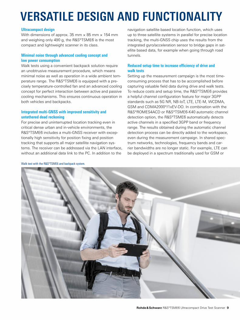
Walk test with the R&S®TSME6 and backpack system.
Ultracompact designWith dimensions of approx. 35 mm × 85 mm × 154 mm and weighing only 490 g, the R&S®TSME6 is the most compact and lightweight scanner in its class.
Minimal noise through advanced cooling concept and low power consumptionWalk tests using a convenient backpack solution require an unobtrusive measurement procedure, which means minimal noise as well as operation in a wide ambient temperature range. The R&S®TSME6 is equipped with a precisely temperaturecontrolled fan and an advanced cooling concept for perfect interaction between active and passive cooling mechanisms. This ensures continuous operation in both vehicles and backpacks.
Integrated multi-GNSS with improved sensitivity and untethered dead reckoningFor precise and uninterrupted location tracking even in critical dense urban and invehicle environments, the R&S®TSME6 includes a multiGNSS receiver with exceptionally high sensitivity for position fixing and position tracking that supports all major satellite navigation systems. The receiver can be addressed via the LAN interface, without an additional data link to the PC. In addition to the
VERSATILE DESIGN AND FUNCTIONALITYnavigation satellite based location function, which uses up to three satellite systems in parallel for precise location tracking, the multiGNSS chip uses the results from the integrated gyro/acceleration sensor to bridge gaps in satellite based data, for example when going through road tunnels.
Reduced setup time to increase efficiency of drive and walk testsSetting up the measurement campaign is the most timeconsuming process that has to be accomplished before capturing valuable field data during drive and walk tests. To reduce costs and setup time, the R&S®TSME6 provides a helpful channel configuration feature for major 3GPP standards such as 5G NR, NBIoT, LTE, LTEM, WCDMA, GSM and CDMA2000®/1xEVDO. In combination with the R&S®ROMES4ACD or R&S®TSME6K40 automatic channel detection option, the R&S®TSME6 automatically detects active channels in a specified 3GPP band or frequency range. The results obtained during the automatic channel detection process can be directly added to the workspace, even during the measurement campaign. In shared spectrum networks, technologies, frequency bands and carrier bandwidths are no longer static. For example, LTE can be deployed in a spectrum traditionally used for GSM or
10
WCDMA. During drive and walk tests in such networks, frequent bandwidth and channel changes can regularly occur in urban and rural environments depending on the rollout strategy. To speed up the detection process or release signal processing capacity for other parallel measurement tasks, users can enhance the automatic channel detection feature with an optional spectrum scan.
Without the R&S®ROMES4ACD option, automatic channel detection is provided by the R&S®TSME6K40 option via the open ViCom interface, which currently supports 5G NR, NBIoT, LTE, WCDMA and CDMA2000®/1xEVDO.
NB-IoT/Cat NB1 measurementsThe R&S®TSME6K34 option enables the R&S®TSME6 to measure in NBIoT/Cat NB1 networks. NBIoT/Cat NB1 is a 3GPP standard for connecting a huge number of devices, such as smart meters, to the internet of things (IoT). While traditional LTE standards mainly enhance throughput and network capacity, NBIoT/Cat NB1 focuses on low power consumption for IoT devices and maximum availability of the connection, especially indoors. Indoor measurements require lightweight and ultracompact scanners with low power consumption. For coverage validation, troubleshooting and optimization, the R&S®TSME6 measures signal power and quality and the power to interference and noise ratio on each available physical cell ID based on synchronization and reference signals. To efficiently integrate the NBIoT carrier into the available spectrum, the standard provides three operating modes. The R&S®TSME6 supports all three modes.
The most spectrumefficient mode is the LTE inband operating mode, where the NBIoT carrier uses the spectrum of one LTE physical resource block (PRB). The guard band and standalone operating modes allow NBIoT deployments independent of the LTE spectrum. NBIoT measurements can be run simultaneously with measurements on other technologies such as GSM, LTE and (W)CDMA (with the appropriate R&S®TSME6 options). For optimization or when troubleshooting, the impact of the NBIoT spectrum on the adjacent GSM/LTE/(W)CDMA spectrum and vice versa can be validated.
LTE-M measurementsLTEM is another 3GPP standard for connecting things to the internet. LTEM addresses use cases other than NBIoT, for instance voice (VoLTE) and mobility. It also provides higher data rates. LTEM is based on legacy LTE and reuses some of the cellspecific signals. Like NBIoT, LTEM uses smart mechanisms to enlarge the link budget. One of these mechanisms is frequency hopping to overcome fading and areas of bad SINR ( resulting from LTE traffic and other interference) across the LTE spectrum. This is achieved by dividing the LTE carrier into several LTEM narrowbands that can handle LTEM traffic in a
manner that suits the RF environment. The R&S®TSME6 supports LTEM measurements that deliver RF parameters (SINR, RSRP, RSRQ and RSSI) on each of these LTEM narrowbands via a PCI interface to identify, for example, the best narrowband for LTEM data transmission. In R&S®ROMES4, it is also possible to compare all narrowbands at a glance to evaluate the RF environment in the surrounding narrowbands. With fading and interference from LTE traffic and other pilot signals, the RF parameter differences between the narrowbands can be quite remarkable. It is also possible to compare scanner based and module based results to verify if the LTEM module uses the best narrowband for data transmission.
RF power spectrum measurements up to 6 GHz for spectrum clearanceTo overcome capacity problems in mobile networks, additional spectra will be acquired. According to the latest frequency plans, the spectrum from 3.2 GHz to 6 GHz will be used for additional LTE carriers as well as for the fifth generation of mobile networks, which is ready to become the main technology and is expected to grow significantly during the next few years. To ensure the best quality of service after a commercial network rollout, spectrum measurements during the early engineering phase must ensure that the new spectrum is free of interference. Especially when it comes to overlapping spectra with WiFi, which is heavily occupied by WiFi access points, a general picture of the spectrum occupancy is needed in order to detect the noise floor and identify critical areas for network rollout regarding the signal to interference and noise ratio.
Advanced measurements for deep network insightsPassive scanner measurements are no longer limited to measuring specific signals or channels or decoding SIB/layer 3 information. Using intelligent and optimized signal processing algorithms, the R&S®TSME6 is able to offer deep network insights that go beyond pure RF parameters.
Dedicated measurements on reference signals of each LTE resource block give the complete picture of broadband carriers. They also provide insights into fading effects, wideband and narrowband interference and inband operation of advanced IoT technologies. These technologies occupy LTE resource blocks such as LTEM or Cat NB1/NBIoT and might affect adjacent subbands.
During a drive test, R&S®ROMES4 can use measurement and location data delivered by the R&S®TSME6 to estimate the geographic position of the base stations. This calculation is fast and accurate. 5G NR, GSM, WCDMA, LTE, NBIoT, CDMA2000®/1xEVDO and TETRA networks are supported in parallel. This unique feature enables users to quickly generate a base station list for export or graphic display.
Rohde & Schwarz R&S®TSME6 Ultracompact Drive Test Scanner 11
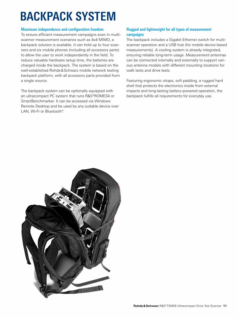
BACKPACK SYSTEMMaximum independence and configuration freedom To ensure efficient measurement campaigns even in multiscanner measurement scenarios such as 4x4 MIMO, a backpack solution is available. It can hold up to four scanners and six mobile phones (including all accessory parts) to allow the user to work independently in the field. To reduce valuable hardware setup time, the batteries are charged inside the backpack. The system is based on the wellestablished Rohde & Schwarz mobile network testing backpack platform, with all accessory parts provided from a single source.
The backpack system can be optionally equipped with an ultracompact PC system that runs R&S®ROMES4 or SmartBenchmarker. It can be accessed via Windows Remote Desktop and be used by any suitable device over LAN, WiFi or Bluetooth®.
Rugged and lightweight for all types of measurement campaignsThe backpack includes a Gigabit Ethernet switch for multi scanner operation and a USB hub (for mobile device based measurements). A cooling system is already integrated, ensuring reliable longterm usage. Measurement antennas can be connected internally and externally to support various antenna models with different mounting locations for walk tests and drive tests.
Featuring ergonomic straps, soft padding, a rugged hard shell that protects the electronics inside from external impacts and longlasting batterypowered operation, the backpack fulfills all requirements for everyday use.
12
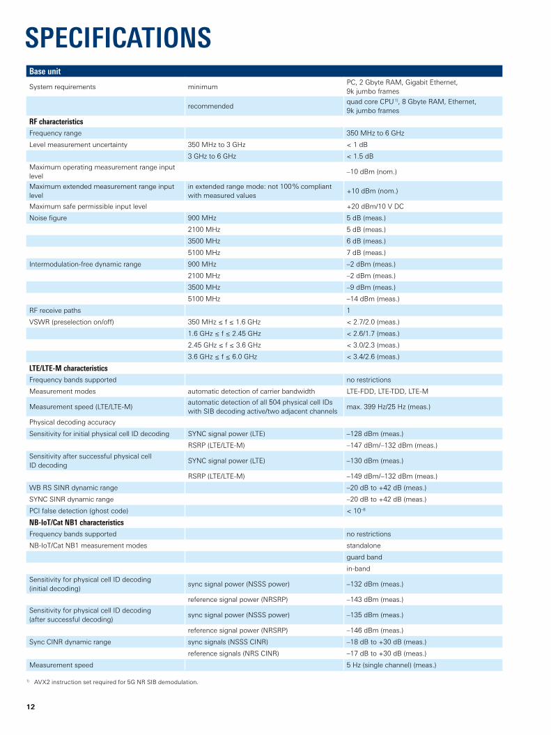
SPECIFICATIONSBase unit
System requirements minimumPC, 2 Gbyte RAM, Gigabit Ethernet, 9k jumbo frames
recommendedquad core CPU 1), 8 Gbyte RAM, Ethernet, 9k jumbo frames
RF characteristicsFrequency range 350 MHz to 6 GHz
Level measurement uncertainty 350 MHz to 3 GHz < 1 dB
3 GHz to 6 GHz < 1.5 dB
Maximum operating measurement range input level
–10 dBm (nom.)
Maximum extended measurement range input level
in extended range mode: not 100 % compliant with measured values
+10 dBm (nom.)
Maximum safe permissible input level +20 dBm/10 V DC
Noise figure 900 MHz 5 dB (meas.)
2100 MHz 5 dB (meas.)
3500 MHz 6 dB (meas.)
5100 MHz 7 dB (meas.)
Intermodulationfree dynamic range 900 MHz –2 dBm (meas.)
2100 MHz –2 dBm (meas.)
3500 MHz –9 dBm (meas.)
5100 MHz –14 dBm (meas.)
RF receive paths 1
VSWR (preselection on/off) 350 MHz ≤ f ≤ 1.6 GHz < 2.7/2.0 (meas.)
1.6 GHz ≤ f ≤ 2.45 GHz < 2.6/1.7 (meas.)
2.45 GHz ≤ f ≤ 3.6 GHz < 3.0/2.3 (meas.)
3.6 GHz ≤ f ≤ 6.0 GHz < 3.4/2.6 (meas.)
LTE/LTE-M characteristicsFrequency bands supported no restrictions
Measurement modes automatic detection of carrier bandwidth LTEFDD, LTETDD, LTEM
Measurement speed (LTE/LTEM)automatic detection of all 504 physical cell IDs with SIB decoding active/two adjacent channels
max. 399 Hz/25 Hz (meas.)
Physical decoding accuracy
Sensitivity for initial physical cell ID decoding SYNC signal power (LTE) –128 dBm (meas.)
RSRP (LTE/LTEM) –147 dBm/–132 dBm (meas.)
Sensitivity after successful physical cell ID decoding
SYNC signal power (LTE) –130 dBm (meas.)
RSRP (LTE/LTEM) –149 dBm/–132 dBm (meas.)
WB RS SINR dynamic range –20 dB to +42 dB (meas.)
SYNC SINR dynamic range –20 dB to +42 dB (meas.)
PCI false detection (ghost code) < 10–8
NB-IoT/Cat NB1 characteristicsFrequency bands supported no restrictions
NBIoT/Cat NB1 measurement modes standalone
guard band
inband
Sensitivity for physical cell ID decoding (initial decoding)
sync signal power (NSSS power) –132 dBm (meas.)
reference signal power (NRSRP) –143 dBm (meas.)
Sensitivity for physical cell ID decoding (after successful decoding)
sync signal power (NSSS power) –135 dBm (meas.)
reference signal power (NRSRP) –146 dBm (meas.)
Sync CINR dynamic range sync signals (NSSS CINR) –18 dB to +30 dB (meas.)
reference signals (NRS CINR) –17 dB to +30 dB (meas.)
Measurement speed 5 Hz (single channel) (meas.)
1) AVX2 instruction set required for 5G NR SIB demodulation.
Rohde & Schwarz R&S®TSME6 Ultracompact Drive Test Scanner 13
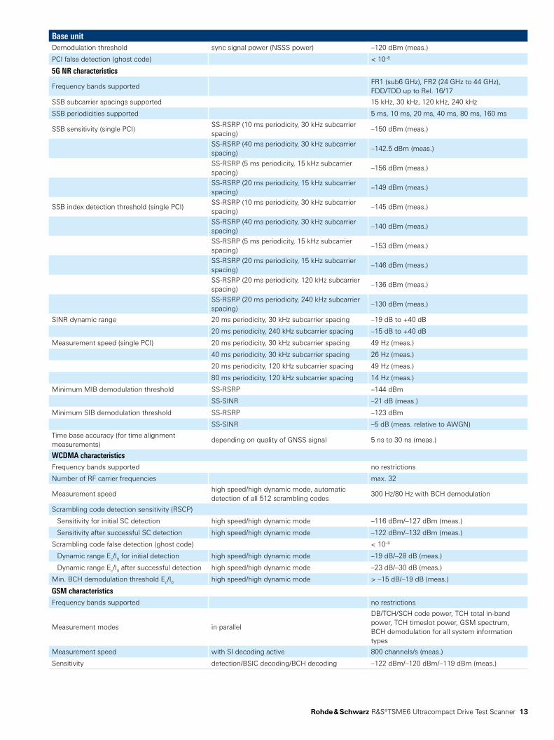
Base unitDemodulation threshold sync signal power (NSSS power) –120 dBm (meas.)
PCI false detection (ghost code) < 10–8
5G NR characteristics
Frequency bands supportedFR1 (sub6 GHz), FR2 (24 GHz to 44 GHz), FDD/TDD up to Rel. 16/17
SSB subcarrier spacings supported 15 kHz, 30 kHz, 120 kHz, 240 kHz
SSB periodicities supported 5 ms, 10 ms, 20 ms, 40 ms, 80 ms, 160 ms
SSB sensitivity (single PCI)SSRSRP (10 ms periodicity, 30 kHz subcarrier spacing)
–150 dBm (meas.)
SSRSRP (40 ms periodicity, 30 kHz subcarrier spacing)
–142.5 dBm (meas.)
SSRSRP (5 ms periodicity, 15 kHz subcarrier spacing)
–156 dBm (meas.)
SSRSRP (20 ms periodicity, 15 kHz subcarrier spacing)
–149 dBm (meas.)
SSB index detection threshold (single PCI)SSRSRP (10 ms periodicity, 30 kHz subcarrier spacing)
–145 dBm (meas.)
SSRSRP (40 ms periodicity, 30 kHz subcarrier spacing)
–140 dBm (meas.)
SSRSRP (5 ms periodicity, 15 kHz subcarrier spacing)
–153 dBm (meas.)
SSRSRP (20 ms periodicity, 15 kHz subcarrier spacing)
–146 dBm (meas.)
SSRSRP (20 ms periodicity, 120 kHz subcarrier spacing)
–136 dBm (meas.)
SSRSRP (20 ms periodicity, 240 kHz subcarrier spacing)
–130 dBm (meas.)
SINR dynamic range 20 ms periodicity, 30 kHz subcarrier spacing –19 dB to +40 dB
20 ms periodicity, 240 kHz subcarrier spacing –15 dB to +40 dB
Measurement speed (single PCI) 20 ms periodicity, 30 kHz subcarrier spacing 49 Hz (meas.)
40 ms periodicity, 30 kHz subcarrier spacing 26 Hz (meas.)
20 ms periodicity, 120 kHz subcarrier spacing 49 Hz (meas.)
80 ms periodicity, 120 kHz subcarrier spacing 14 Hz (meas.)
Minimum MIB demodulation threshold SSRSRP –144 dBm
SSSINR –21 dB (meas.)
Minimum SIB demodulation threshold SSRSRP –123 dBm
SSSINR –5 dB (meas. relative to AWGN)
Time base accuracy (for time alignment measurements)
depending on quality of GNSS signal 5 ns to 30 ns (meas.)
WCDMA characteristicsFrequency bands supported no restrictions
Number of RF carrier frequencies max. 32
Measurement speedhigh speed/high dynamic mode, automatic detection of all 512 scrambling codes
300 Hz/80 Hz with BCH demodulation
Scrambling code detection sensitivity (RSCP)
Sensitivity for initial SC detection high speed/high dynamic mode –116 dBm/–127 dBm (meas.)
Sensitivity after successful SC detection high speed/high dynamic mode –122 dBm/–132 dBm (meas.)
Scrambling code false detection (ghost code) < 10–9
Dynamic range Ec/I0 for initial detection high speed/high dynamic mode –19 dB/–28 dB (meas.)
Dynamic range Ec/I0 after successful detection high speed/high dynamic mode –23 dB/–30 dB (meas.)
Min. BCH demodulation threshold Ec/I0 high speed/high dynamic mode > –15 dB/–19 dB (meas.)
GSM characteristicsFrequency bands supported no restrictions
Measurement modes in parallel
DB/TCH/SCH code power, TCH total inband power, TCH timeslot power, GSM spectrum, BCH demodulation for all system information types
Measurement speed with SI decoding active 800 channels/s (meas.)
Sensitivity detection/BSIC decoding/BCH decoding –122 dBm/–120 dBm/–119 dBm (meas.)
14
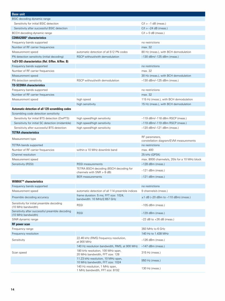
Base unitBSIC decoding dynamic range
Sensitivity for initial BSIC detection C/I > –1 dB (meas.)
Sensitivity after successful BSIC detection C/I > –24 dB (meas.)
BCCH decoding dynamic range C/I > 0 dB (meas.)
CDMA2000® characteristicsFrequency bands supported no restrictions
Number of RF carrier frequencies max. 32
Measurement speed automatic detection of all 512 PN codes 80 Hz (meas.), with BCH demodulation
PN detection sensitivity (initial decoding) RSCP without/with demodulation –130 dBm/–125 dBm (meas.)
1xEV-DO characteristics (Rel. 0/Rev. A/Rev. B)Frequency bands supported no restrictions
Number of RF carrier frequencies max. 32
Measurement speed 30 Hz (meas.), with BCH demodulation
PN detection sensitivity RSCP without/with demodulation –130 dBm/–125 dBm (meas.)
TD-SCDMA characteristicsFrequency bands supported no restrictions
Number of RF carrier frequencies max. 32
Measurement speed high speed 115 Hz (meas.), with BCH demodulation
high sensitivity 15 Hz (meas.), with BCH demodulation
Automatic detection of all 128 scrambling codesScrambling code detection sensitivity
Sensitivity for initial BTS detection (DwPTS) high speed/high sensitivity –119 dBm/–118 dBm RSCP (meas.)
Sensitivity for initial SC detection (midamble) high speed/high sensitivity –119 dBm/–119 dBm RSCP (meas.)
Sensitivity after successful BTS detection high speed/high sensitivity –120 dBm/–121 dBm (meas.)
TETRA characteristics
Measurement typeRF parameters, constellation diagram/EVM measurements
TETRA bands supported no restrictions
Number of RF carrier frequencies within a 10 MHz downlink band max. 400
Channel resolution 25 kHz (QPSK)
Measurement speed max. 8000 channels/s, 20/s for a 10 MHz block
Sensitivity (RSSI) RSSI measurements –128 dBm (meas.)
TETRA BSCH decoding (BSCH decoding for channels with SNR > 8 dB)
–121 dBm (meas.)
BER measurements –121 dBm (meas.)
WiMAX™ characteristicsFrequency bands supported no restrictions
Measurement speed automatic detection of all 114 preamble indices 9 channels/s (meas.)
Preamble decoding accuracyframe duration: 5 ms; FFT size: 1024, bandwidth: 10 MHz/2.657 GHz
±1 dB (–20 dBm to –110 dBm) (meas.)
Sensitivity for initial preamble decoding (10 MHz bandwidth)
RSSI –105 dBm (meas.)
Sensitivity after successful preamble decoding (10 MHz bandwidth)
RSSI –129 dBm (meas.)
SINR dynamic range –22 dB to +26 dB (meas.)
RF power scanFrequency range 350 MHz to 6 GHz
Frequency resolution 140 Hz to 1.438 MHz
Sensitivity22.46 kHz (RMS) frequency resolution, at 900 MHz
–126 dBm (meas.)
140 Hz resolution bandwidth, RMS, at 900 MHz –147 dBm (meas.)
Scan speed180 kHz resolution, 100 MHz span, 20 MHz bandwidth, FFT size: 128
315 Hz (meas.)
11.23 kHz resolution, 10 MHz span, 10 MHz bandwidth, FFT size: 1024
950 Hz (meas.)
140 Hz resolution, 1 MHz span, 1 MHz bandwidth, FFT size: 8192
130 Hz (meas.)
Rohde & Schwarz R&S®TSME6 Ultracompact Drive Test Scanner 15
Base unit
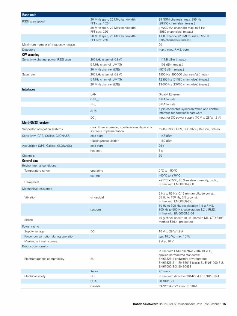
RSSI scan speed20 MHz span, 20 MHz bandwidth, FFT size: 1024
99 GSM channels: max. 995 Hz (98 505 channels/s) (meas.)
20 MHz span, 20 MHz bandwidth, FFT size: 256
4 WCDMA channels: max. 995 Hz (3980 channels/s) (meas.)
20 MHz span, 20 MHz bandwidth, FFT size: 256
1 LTE channel (20 MHz): max. 995 Hz (995 channels/s) (meas.)
Maximum number of frequency ranges 20
Detectors max., min., RMS, auto
CW scanningSensitivity channel power RSSI scan 200 kHz channel (GSM) –117.5 dBm (meas.)
5 MHz channel (UMTS) –103 dBm (meas.)
20 MHz channel (LTE) –97.5 dBm (meas.)
Scan rate 200 kHz channel (GSM) 1900 Hz (190 000 channels/s) (meas.)
5 MHz channel (UMTS) 12 995 Hz (51 980 channels/s) (meas.)
20 MHz channel (LTE) 13 000 Hz (13 000 channels/s) (meas.)
InterfacesLAN Gigabit Ethernet
GPSAnt SMA female
RFIn SMA female
AUX6pin connector, synchronization and control interface for additional hardware
DCIn input for DC power supply (10 V to 28 V/1.8 A)
Multi-GNSS receiver
Supported navigation systemsmax. three in parallel, combinations depend on software implementation
multiGNSS: GPS, GLONASS, BeiDou, Galileo
Sensitivity (GPS, Galileo, GLONASS) cold start –148 dBm
tracking/reacquisition –160 dBm
Acquisition (GPS, Galileo, GLONASS) cold start 26 s
hot start 1 s
Channels 50
General dataEnvironmental conditions
Temperature range operating 0 °C to +50 °C
storage –40 °C to +70 °C
Damp heat+25 °C/+55 °C, 95 % relative humidity, cyclic, in line with EN 60068230
Mechanical resistance
Vibration sinusoidal5 Hz to 55 Hz, 0.15 mm amplitude const., 55 Hz to 150 Hz, 0.5 g const., in line with EN 6006826
random10 Hz to 300 Hz, acceleration 1.9 g RMS, 300 Hz to 500 Hz, acceleration 1.2 g RMS, in line with EN 60068264
Shock40 g shock spectrum, in line with MILSTD810E, method 516.4, procedure I
Power rating
Supply voltage DC 10 V to 28 V/1.8 A
Power consumption during operation typ. 10.5 W, max. 13 W
Maximum inrush current 2 A at 10 V
Product conformity
Electromagnetic compatibility EU
in line with EMC directive 2004/108/EC, applied harmonized standards: EN 613261 (industrial environment), EN 6132621, EN 55011 (class B), EN 6100032, EN 6100033, EN 50498
Korea KC mark
Electrical safety EU in line with directive 2014/35/EU: EN 610101
USA UL 610101
Canada CAN/CSAC22.2 no. 610101
16
Base unit
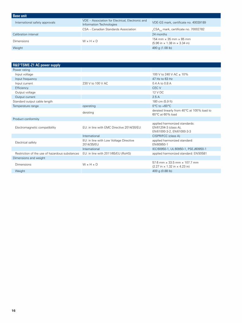
International safety approvalsVDE – Association for Electrical, Electronic and Information Technologies
VDEGS mark, certificate no. 40039189
CSA – Canadian Standards Association CCSAUS mark, certificate no. 70002782
Calibration interval 24 months
Dimensions W × H × D154 mm × 35 mm × 85 mm (5.96 in × 1.38 in × 3.34 in)
Weight 490 g (1.08 lb)
R&S®TSME-Z1 AC power supplyPower rating
Input voltage 100 V to 240 V AC ± 10 %
Input frequency 47 Hz to 63 Hz
Input current 230 V to 100 V AC 0.4 A to 0.8 A
Efficiency CEC V
Output voltage 12 V DC
Output current 2.5 A
Standard output cable length 180 cm (5.9 ft)
Temperature range operating 0 °C to +60 °C
deratingderated linearly from 40 °C at 100 % load to 60 °C at 60 % load
Product conformity
Electromagnetic compatibility EU: in line with EMC Directive 2014/30/EUapplied harmonized standards: EN 612043 (class A), EN 6100032, EN 6100033
International CISPR/FCC (class A)
Electrical safety EU: in line with Low Voltage Directive 2014/35/EU
applied harmonized standard: EN 609501
International IEC 609501, UL 609501, PSE J609501
Restriction of the use of hazardous substances EU: in line with 2011/65/EU (RoHS) applied harmonized standard: EN 50581
Dimensions and weight
Dimensions W × H × D 57.6 mm × 33.5 mm × 107.7 mm (2.27 in × 1.32 in × 4.23 in)
Weight 400 g (0.88 lb)
Rohde & Schwarz R&S®TSME6 Ultracompact Drive Test Scanner 17
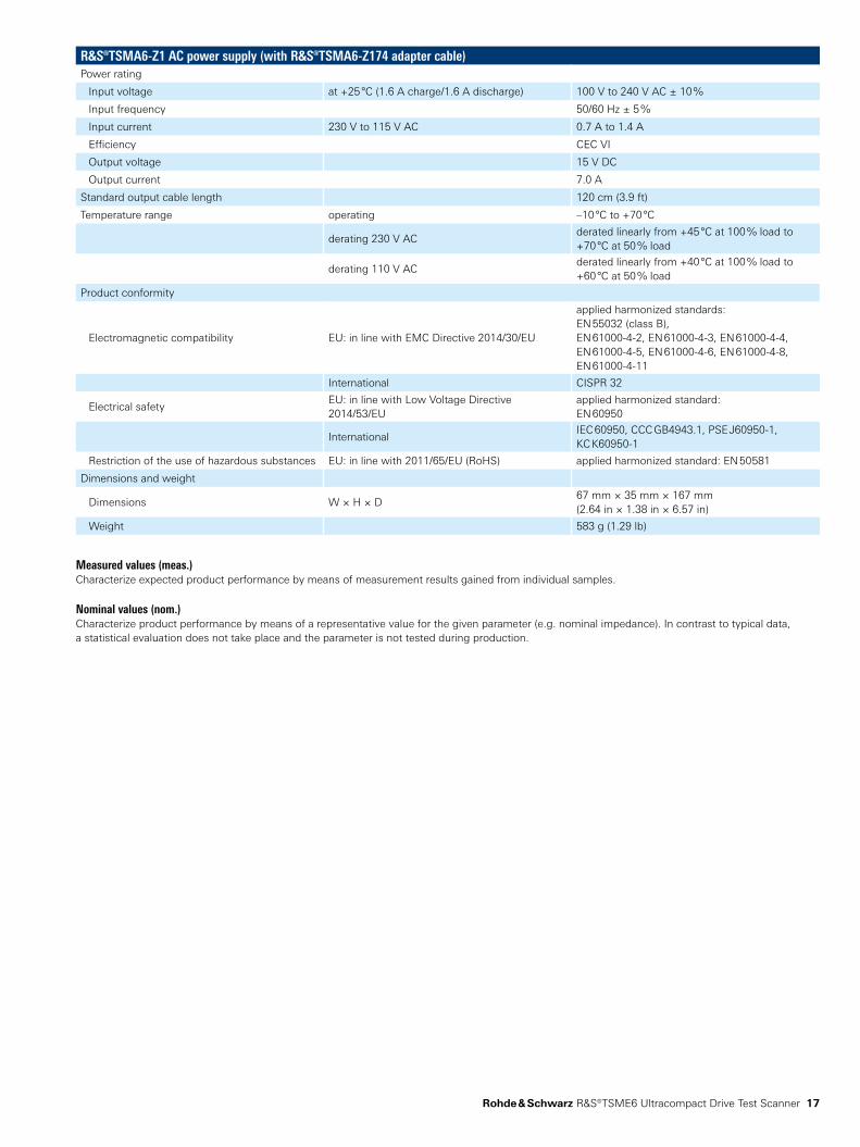
R&S®TSMA6-Z1 AC power supply (with R&S®TSMA6-Z174 adapter cable)Power rating
Input voltage at +25 °C (1.6 A charge/1.6 A discharge) 100 V to 240 V AC ± 10 %
Input frequency 50/60 Hz ± 5 %
Input current 230 V to 115 V AC 0.7 A to 1.4 A
Efficiency CEC VI
Output voltage 15 V DC
Output current 7.0 A
Standard output cable length 120 cm (3.9 ft)
Temperature range operating –10 °C to +70 °C
derating 230 V ACderated linearly from +45 °C at 100 % load to +70 °C at 50 % load
derating 110 V ACderated linearly from +40 °C at 100 % load to +60 °C at 50 % load
Product conformity
Electromagnetic compatibility EU: in line with EMC Directive 2014/30/EU
applied harmonized standards: EN 55032 (class B), EN 6100042, EN 6100043, EN 6100044, EN 6100045, EN 6100046, EN 6100048, EN 61000411
International CISPR 32
Electrical safetyEU: in line with Low Voltage Directive 2014/53/EU
applied harmonized standard: EN 60950
InternationalIEC 60950, CCC GB4943.1, PSE J609501, KC K609501
Restriction of the use of hazardous substances EU: in line with 2011/65/EU (RoHS) applied harmonized standard: EN 50581
Dimensions and weight
Dimensions W × H × D67 mm × 35 mm × 167 mm (2.64 in × 1.38 in × 6.57 in)
Weight 583 g (1.29 lb)
Measured values (meas.)Characterize expected product performance by means of measurement results gained from individual samples.
Nominal values (nom.)Characterize product performance by means of a representative value for the given parameter (e.g. nominal impedance). In contrast to typical data, a statistical evaluation does not take place and the parameter is not tested during production.
18
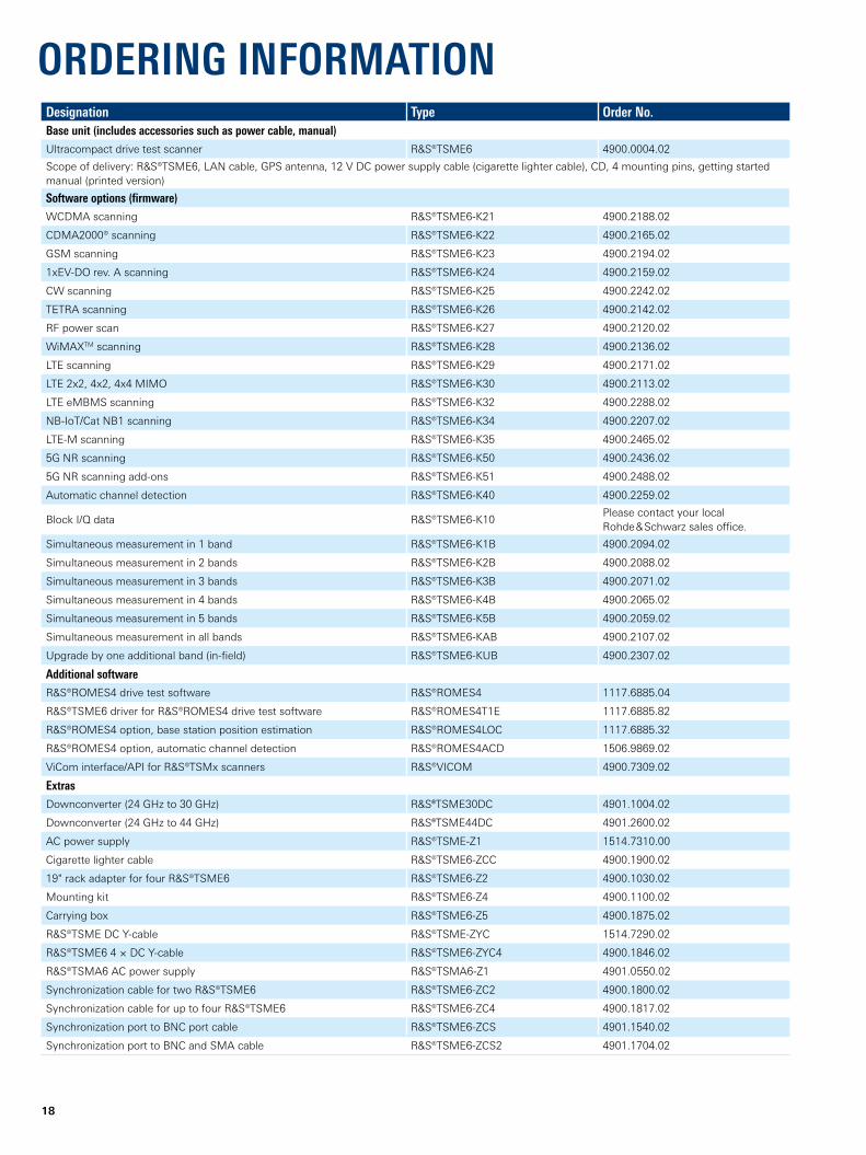
ORDERING INFORMATIONDesignation Type Order No.Base unit (includes accessories such as power cable, manual)Ultracompact drive test scanner R&S®TSME6 4900.0004.02
Scope of delivery: R&S®TSME6, LAN cable, GPS antenna, 12 V DC power supply cable (cigarette lighter cable), CD, 4 mounting pins, getting started manual (printed version)
Software options (firmware)WCDMA scanning R&S®TSME6K21 4900.2188.02
CDMA2000® scanning R&S®TSME6K22 4900.2165.02
GSM scanning R&S®TSME6K23 4900.2194.02
1xEVDO rev. A scanning R&S®TSME6K24 4900.2159.02
CW scanning R&S®TSME6K25 4900.2242.02
TETRA scanning R&S®TSME6K26 4900.2142.02
RF power scan R&S®TSME6K27 4900.2120.02
WiMAXTM scanning R&S®TSME6K28 4900.2136.02
LTE scanning R&S®TSME6K29 4900.2171.02
LTE 2x2, 4x2, 4x4 MIMO R&S®TSME6K30 4900.2113.02
LTE eMBMS scanning R&S®TSME6K32 4900.2288.02
NBIoT/Cat NB1 scanning R&S®TSME6K34 4900.2207.02
LTEM scanning R&S®TSME6K35 4900.2465.02
5G NR scanning R&S®TSME6K50 4900.2436.02
5G NR scanning addons R&S®TSME6K51 4900.2488.02
Automatic channel detection R&S®TSME6K40 4900.2259.02
Block I/Q data R&S®TSME6K10Please contact your local Rohde & Schwarz sales office.
Simultaneous measurement in 1 band R&S®TSME6K1B 4900.2094.02
Simultaneous measurement in 2 bands R&S®TSME6K2B 4900.2088.02
Simultaneous measurement in 3 bands R&S®TSME6K3B 4900.2071.02
Simultaneous measurement in 4 bands R&S®TSME6K4B 4900.2065.02
Simultaneous measurement in 5 bands R&S®TSME6K5B 4900.2059.02
Simultaneous measurement in all bands R&S®TSME6KAB 4900.2107.02
Upgrade by one additional band (infield) R&S®TSME6KUB 4900.2307.02
Additional softwareR&S®ROMES4 drive test software R&S®ROMES4 1117.6885.04
R&S®TSME6 driver for R&S®ROMES4 drive test software R&S®ROMES4T1E 1117.6885.82
R&S®ROMES4 option, base station position estimation R&S®ROMES4LOC 1117.6885.32
R&S®ROMES4 option, automatic channel detection R&S®ROMES4ACD 1506.9869.02
ViCom interface/API for R&S®TSMx scanners R&S®VICOM 4900.7309.02
ExtrasDownconverter (24 GHz to 30 GHz) R&S®TSME30DC 4901.1004.02
Downconverter (24 GHz to 44 GHz) R&S®TSME44DC 4901.2600.02
AC power supply R&S®TSMEZ1 1514.7310.00
Cigarette lighter cable R&S®TSME6ZCC 4900.1900.02
19" rack adapter for four R&S®TSME6 R&S®TSME6Z2 4900.1030.02
Mounting kit R&S®TSME6Z4 4900.1100.02
Carrying box R&S®TSME6Z5 4900.1875.02
R&S®TSME DC Ycable R&S®TSMEZYC 1514.7290.02
R&S®TSME6 4 × DC Ycable R&S®TSME6ZYC4 4900.1846.02
R&S®TSMA6 AC power supply R&S®TSMA6Z1 4901.0550.02
Synchronization cable for two R&S®TSME6 R&S®TSME6ZC2 4900.1800.02
Synchronization cable for up to four R&S®TSME6 R&S®TSME6ZC4 4900.1817.02
Synchronization port to BNC port cable R&S®TSME6ZCS 4901.1540.02
Synchronization port to BNC and SMA cable R&S®TSME6ZCS2 4901.1704.02
Rohde & Schwarz R&S®TSME6 Ultracompact Drive Test Scanner 19
The Bluetooth® word mark and logos are registered trademarks owned by the Bluetooth SIG, Inc. and any use of such marks by Rohde & Schwarz is under license.CDMA2000® is a registered trademark of the Telecommunications Industry Association (TIA USA).WiMAX Forum is a registered trademark of the WiMAX Forum. WiMAX, the WiMAX Forum logo, WiMAX Forum Certified and the WiMAX Forum Certified logo are trademarks of the WiMAX Forum.
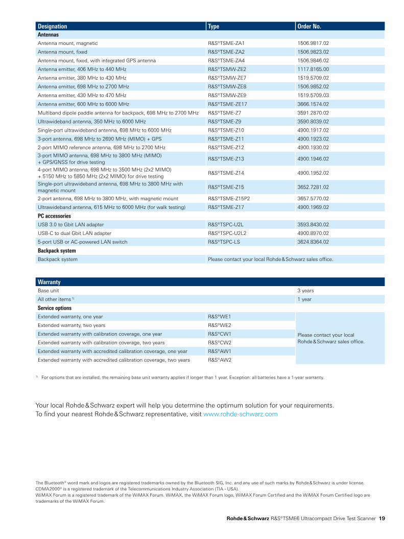
Designation Type Order No.AntennasAntenna mount, magnetic R&S®TSMEZA1 1506.9817.02
Antenna mount, fixed R&S®TSMEZA2 1506.9823.02
Antenna mount, fixed, with integrated GPS antenna R&S®TSMEZA4 1506.9846.02
Antenna emitter, 406 MHz to 440 MHz R&S®TSMWZE2 1117.8165.00
Antenna emitter, 380 MHz to 430 MHz R&S®TSMWZE7 1519.5709.02
Antenna emitter, 698 MHz to 2700 MHz R&S®TSMWZE8 1506.9852.02
Antenna emitter, 430 MHz to 470 MHz R&S®TSMWZE9 1519.5709.03
Antenna emitter, 600 MHz to 6000 MHz R&S®TSMEZE17 3666.1574.02
Multiband dipole paddle antenna for backpack, 698 MHz to 2700 MHz R&S®TSMEZ7 3591.2870.02
Ultrawideband antenna, 350 MHz to 6000 MHz R&S®TSMEZ9 3590.8039.02
Singleport ultrawideband antenna, 698 MHz to 6000 MHz R&S®TSMEZ10 4900.1917.02
3port antenna, 698 MHz to 2690 MHz (MIMO) + GPS R&S®TSMEZ11 4900.1923.02
2port MIMO reference antenna, 698 MHz to 2700 MHz R&S®TSMEZ12 4900.1930.02
3port MIMO antenna, 698 MHz to 3800 MHz (MIMO) + GPS/GNSS for drive testing
R&S®TSMEZ13 4900.1946.02
4port MIMO antenna, 698 MHz to 3500 MHz (2x2 MIMO) + 5150 MHz to 5850 MHz (2x2 MIMO) for drive testing
R&S®TSMEZ14 4900.1952.02
Singleport ultrawideband antenna, 698 MHz to 3800 MHz with magnetic mount
R&S®TSMEZ15 3652.7281.02
2port antenna, 698 MHz to 3800 MHz, with magnetic mount R&S®TSMEZ15P2 3657.5770.02
Ultrawideband antenna, 615 MHz to 6000 MHz (for walk testing) R&S®TSMEZ17 4900.1969.02
PC accessoriesUSB 3.0 to Gbit LAN adapter R&S®TSPCU2L 3593.8430.02
USBC to dual Gbit LAN adapter R&S®TSPCU2L2 4900.8970.02
5port USB or ACpowered LAN switch R&S®TSPCLS 3624.8364.02
Backpack systemBackpack system Please contact your local Rohde & Schwarz sales office.
WarrantyBase unit 3 years
All other items 1) 1 year
Service optionsExtended warranty, one year R&S®WE1
Please contact your local Rohde & Schwarz sales office.
Extended warranty, two years R&S®WE2
Extended warranty with calibration coverage, one year R&S®CW1
Extended warranty with calibration coverage, two years R&S®CW2
Extended warranty with accredited calibration coverage, one year R&S®AW1
Extended warranty with accredited calibration coverage, two years R&S®AW2
1) For options that are installed, the remaining base unit warranty applies if longer than 1 year. Exception: all batteries have a 1year warranty.
Your local Rohde & Schwarz expert will help you determine the optimum solution for your requirements.To find your nearest Rohde & Schwarz representative, visit www.rohdeschwarz.com
Service that adds value► Worldwide► Local and personalized► Customized and flexible► Uncompromising quality► Long-term dependability
3607
.687
3.12
12.
00 P
DP
/PD
W 1
en
R&S® is a registered trademark of Rohde & Schwarz GmbH & Co. KG Trade names are trademarks of the owners PD 3607.6873.12 | Version 12.00 | August 2021 (jr) R&S®TSME6 Ultracompact Drive Test Scanner Data without tolerance limits is not binding | Subject to change© 2018 2021 Rohde & Schwarz GmbH & Co. KG | 81671 Munich, Germany
Rohde & Schwarz customer supportwww.rohdeschwarz.com/support
Rohde & SchwarzThe Rohde & Schwarz technology group is among the trailblazers when it comes to paving the way for a safer and connected world with its leading solutions in test & measurement, technology systems, and networks & cybersecurity. Founded more than 85 years ago, the group is a reliable partner for industry and government customers around the globe. The independent company is headquartered in Munich, Germany and has an extensive sales and service network with locations in more than 70 countries. www.rohdeschwarz.com
Mobile network testingThe company’s broad and diverse product portfolio for mobile network testing addresses every test scenario in the network lifecycle – from base station installation to network acceptance and network benchmarking, from optimization and troubleshooting to interference hunting and spectrum analysis, from IP application awareness to QoS and QoE of voice, data, video and app based services. www.rohdeschwarz.com/mnt
3607687312