alientech bdmpro userguide.pdf
TRANSCRIPT

BDMPro user guide
Alientech srl electronic performance
1
BDMPro user guide
Alientech srl electronic performance
2
Requisiti Minimi di Sistema Windows 98 SE con 32 Mb di RAM.
Windows NT/2000/XP con 64 Mb di RAM.
Risoluzione minima dello schermo 800x600 a (16 bit).
Porta USB
10 Mb di spazio libero sul disco fisso
Componenti Nella confezione di BDM PRO è contenuto:
Interfaccia Hardware BDM PRO
Cavetto Flat BDM PRO
Alimentatore Interfaccia Hardware
Cavo USB
Schedino convertitore 01 SIEMENS
Schedino convertitore 02 MARELLI MJD
Schedino convertitore 03 DELPHI M.
Strip passo 1.27
Strip Passo 2.56
Manuali istruzioni
BDMPro user guide
Alientech srl electronic performance
3
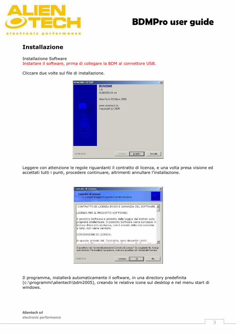
Installazione Installazione Software
Installare il software, prima di collegare la BDM al connettore USB.
Cliccare due volte sul file di installazione.
Leggere con attenzione le regole riguardanti il contratto di licenza, e una volta presa visione ed
accettati tutti i punti, procedere continuare, altrimenti annullare l’installazione.
Il programma, installerà automaticamente il software, in una directory predefinita
(c:\programmi\alientech\bdm2005), creando le relative icone sul desktop e nel menu start di
windows.
BDMPro user guide
Alientech srl electronic performance
4
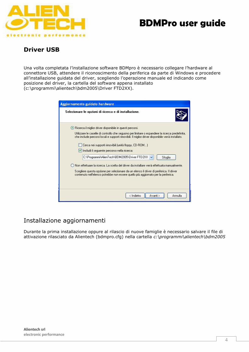
Driver USB
Una volta completata l’installazione software BDMpro è necessario collegare l’hardware al
connettore USB, attendere il riconoscimento della periferica da parte di Windows e procedere
all’installazione guidata del driver, scegliendo l’operazione manuale ed indicando come
posizione del driver, la cartella del software appena installato
(c:\programmi\alientech\bdm2005\Driver FTD2XX).
Installazione aggiornamenti
Durante la prima installazione oppure al rilascio di nuove famiglie è necessario salvare il file di
attivazione rilasciato da Alientech (bdmpro.cfg) nella cartella c:\programmi\alientech\bdm2005
BDMPro user guide
Alientech srl electronic performance
5
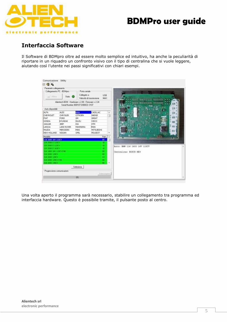
Interfaccia Software Il Software di BDMpro oltre ad essere molto semplice ed intuitivo, ha anche la peculiarità di
riportare in un riquadro un confronto visivo con il tipo di centralina che si vuole leggere,
aiutando così l’utente nei passi significativi con chiari esempi.
Una volta aperto il programma sarà necessario, stabilire un collegamento tra programma ed
interfaccia hardware. Questo è possibile tramite, il pulsante posto al centro.
BDMPro user guide
Alientech srl electronic performance
6
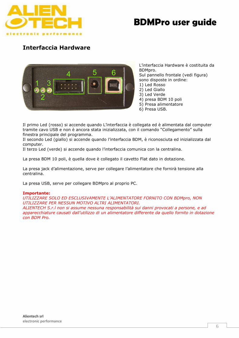
Interfaccia Hardware
L’interfaccia Hardware è costituita da
BDMpro.
Sul pannello frontale (vedi figura)
sono disposte in ordine:
1) Led Rosso
2) Led Giallo
3) Led Verde
4) presa BDM 10 poli
5) Presa alimentatore
6) Presa USB.
Il primo Led (rosso) si accende quando L’interfaccia è collegata ed è alimentata dal computer
tramite cavo USB e non è ancora stata inizializzata, con il comando “Collegamento” sulla
finestra principale del programma.
Il secondo Led (giallo) si accende quando l’interfaccia BDM, è riconosciuta ed inizializzata dal
computer.
Il terzo Led (verde) si accende quando l’interfaccia comunica con la centralina.
La presa BDM 10 poli, è quella dove è collegato il cavetto Flat dato in dotazione.
La presa jack d’alimentazione, serve per collegare l’alimentatore che fornirà tensione alla
centralina.
La presa USB, serve per collegare BDMpro al proprio PC.
Importante:
UTILIZZARE SOLO ED ESCLUSIVAMENTE L’ALIMENTATORE FORNITO CON BDMpro, NON
UTILIZZARE PER NESSUN MOTIVO ALTRI ALIMENTATORI.
ALIENTECH S.r.l non si assume nessuna responsabilità sui danni provocati a persone, e ad
apparecchiature causati dall’utilizzo di un alimentatore differente da quello fornito in dotazione
con BDM Pro.
BDMPro user guide
Alientech srl electronic performance
7
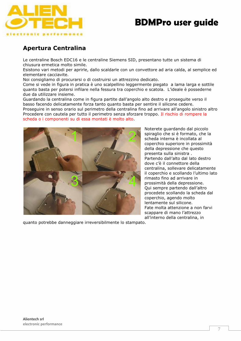
Apertura Centralina Le centraline Bosch EDC16 e le centraline Siemens SID, presentano tutte un sistema di
chiusura ermetica molto simile.
Esistono vari metodi per aprirle, dallo scaldarle con un convettore ad aria calda, al semplice ed
elementare cacciavite.
Noi consigliamo di procurarsi o di costruirsi un attrezzino dedicato.
Come si vede in figura in pratica è uno scalpellino leggermente piegato a lama larga e sottile
quanto basta per potersi infilare nella fessura tra coperchio e scatola. L’ideale è possederne
due da utilizzare insieme.
Guardando la centralina come in figura partite dall’angolo alto destro e proseguite verso il
basso facendo delicatamente forza tanto quanto basta per sentire il silicone cedere.
Proseguire in senso orario sul perimetro della centralina fino ad arrivare all’angolo sinistro altro
Procedere con cautela per tutto il perimetro senza sforzare troppo. Il rischio di rompere la
scheda o i componenti su di essa montati è molto alto.
Noterete guardando dal piccolo
spiraglio che si è formato, che la
scheda interna è incollata al
coperchio superiore in prossimità
della depressione che questo
presenta sulla sinistra .
Partendo dall’alto dal lato destro
dove c’è il connettore della
centralina, sollevare delicatamente
il coperchio e scollando l’ultimo lato
rimasto fino ad arrivare in
prossimità della depressione.
Qui sempre partendo dall’altro
procedete scollando la scheda dal
coperchio, agendo molto
lentamente sul silicone.
Fate molta attenzione a non farvi
scappare di mano l’attrezzo
all’interno della centralina, in
quanto potrebbe danneggiare irreversibilmente lo stampato.
BDMPro user guide
Alientech srl electronic performance
8
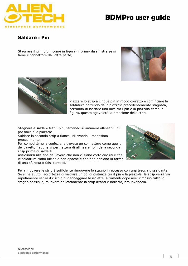
Saldare i Pin
Stagnare il primo pin come in figura (il primo da sinistra se si
tiene il connettore dall’altra parte)
Piazzare lo strip a cinque pin in modo corretto e cominciare la
saldatura partendo dalla piazzola precedentemente stagnata,
cercando di lasciare una luce tra i pin e la piazzola come in
figura, questo agevolerà la rimozione delle strip.
Stagnare e saldare tutti i pin, cercando si rimanere allineati il più
possibile alle piazzole.
Saldare la seconda strip a fianco utilizzando il medesimo
procedimento.
Per comodità nella confezione trovate un connettore come quello
del cavetto flat che vi permetterà di allineare i pin della seconda
strip prima di saldarli.
Assicurarsi alla fine del lavoro che non ci siano corto circuiti e che
le saldature siano lucide e non opache e che non abbiano la forma
di una sferetta o falsi contatti.
Per rimuovere le strip è sufficiente rimuovere lo stagno in eccesso con una treccia dissaldante.
Se si ha avuto l’accortezza di lasciare un po’ di distanza tra il pin e la piazzola, la strip verrà via
rapidamente senza il rischio di danneggiare le isolette, altrimenti dopo aver rimosso tutto lo
stagno possibile, muovere delicatamente la strip avanti e indietro, rimuovendola.
BDMPro user guide
Alientech srl electronic performance
9
System’s Minimum Requirements Windows 98 SE with 32 Mb of RAM.
Windows NT/2000/XP with 64 Mb of RAM.
Screen minimum resolution 800x600 (16 bit).
USB Port
10 Mb of free space on hard disk
Components BDM PRO box includes:
BDM PRO Hardware interface
BDM PRO Flat cable
Hardware interface power supplier
USB cable
01 SIEMENS Card
02 MARELLI MJD Card
03 DELPHI M. Card
Strip line pitch 1.27
Strip line pitch 2.56
Instruction manual
Connector to line up pins

BDMPro user guide
Alientech srl electronic performance
10
Installation Software Installation
IMPORTANT: First install the software, then link BDM to USB connector.
Double click on installation file.
Carefully read the rules of the license contract, and after you have read and
accepted all points, choose whether to continue or annul the installation.
After your acceptance, the program will automatically install the software, in a determined directory
(c:\programs\alientech\bdm2005), creating the relative icon on the desktop and also in
windows start menu.
BDMPro user guide
Alientech srl electronic performance
11
USB Driver
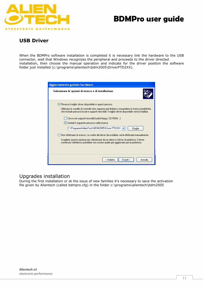
When the BDMPro software installation is completed it is necessary link the hardware to the USB
connector, wait that Windows recognizes the peripheral and proceeds to the driver directed
installation, then choose the manual operation and indicate for the driver position the software
folder just installed (c:\programs\alientech\bdm2005\DriverFTD2XX).
Upgrades installation During the first installation or at the issue of new families it’s necessary to save the activation
file given by Alientech (called bdmpro.cfg) in the folder c:\programs\alientech\bdm2005
BDMPro user guide
Alientech srl electronic performance
12
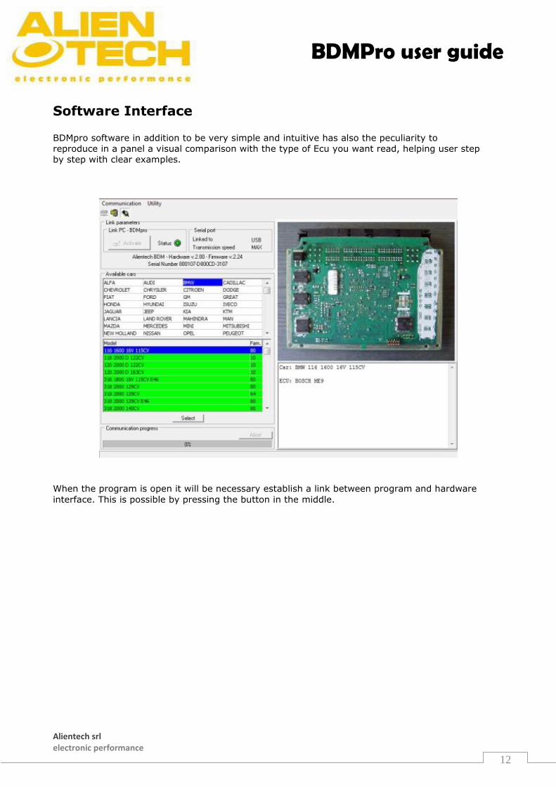
Software Interface BDMpro software in addition to be very simple and intuitive has also the peculiarity to
reproduce in a panel a visual comparison with the type of Ecu you want read, helping user step
by step with clear examples.
When the program is open it will be necessary establish a link between program and hardware
interface. This is possible by pressing the button in the middle.
BDMPro user guide
Alientech srl electronic performance
13
Hardware Interface
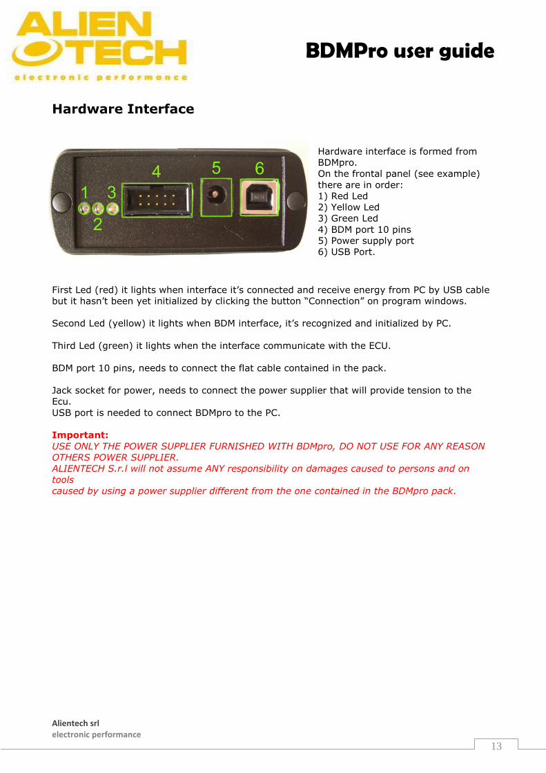
Hardware interface is formed from
BDMpro.
On the frontal panel (see example)
there are in order:
1) Red Led
2) Yellow Led
3) Green Led
4) BDM port 10 pins
5) Power supply port
6) USB Port.
First Led (red) it lights when interface it’s connected and receive energy from PC by USB cable
but it hasn’t been yet initialized by clicking the button “Connection” on program windows.
Second Led (yellow) it lights when BDM interface, it’s recognized and initialized by PC.
Third Led (green) it lights when the interface communicate with the ECU.
BDM port 10 pins, needs to connect the flat cable contained in the pack.
Jack socket for power, needs to connect the power supplier that will provide tension to the
Ecu.
USB port is needed to connect BDMpro to the PC.
Important:
USE ONLY THE POWER SUPPLIER FURNISHED WITH BDMpro, DO NOT USE FOR ANY REASON
OTHERS POWER SUPPLIER.
ALIENTECH S.r.l will not assume ANY responsibility on damages caused to persons and on
tools
caused by using a power supplier different from the one contained in the BDMpro pack.
BDMPro user guide
Alientech srl electronic performance
14
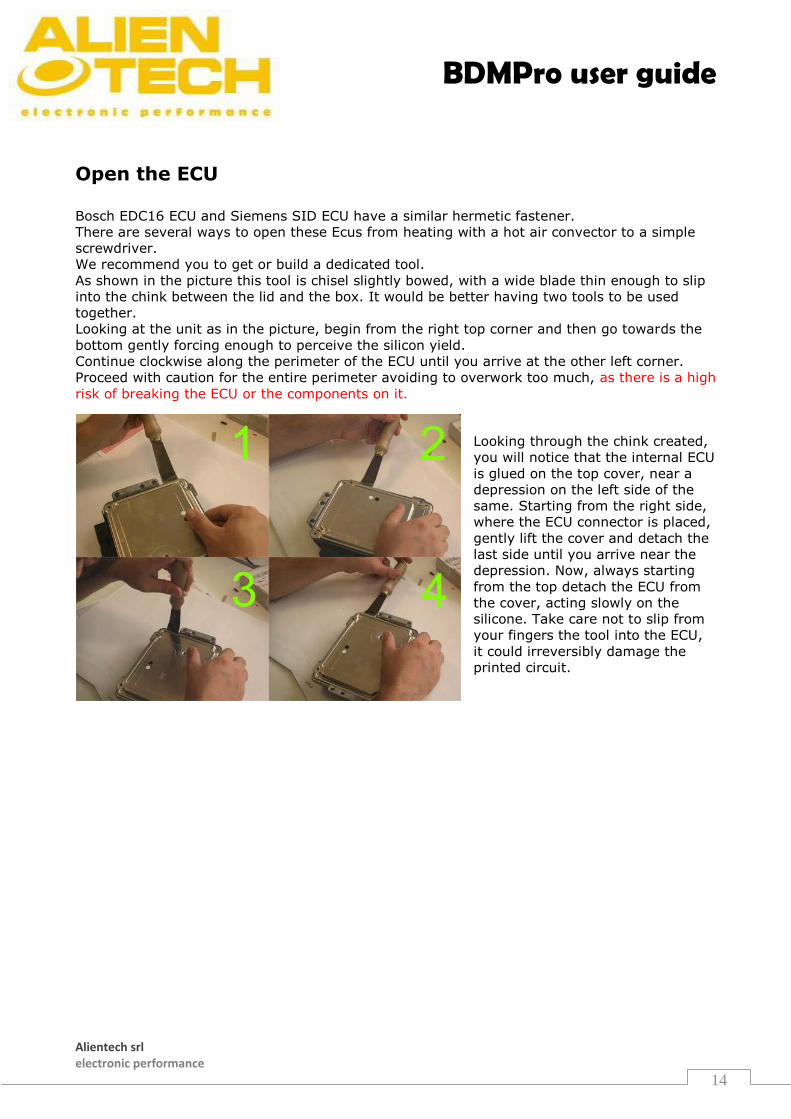
Open the ECU Bosch EDC16 ECU and Siemens SID ECU have a similar hermetic fastener.
There are several ways to open these Ecus from heating with a hot air convector to a simple
screwdriver.
We recommend you to get or build a dedicated tool.
As shown in the picture this tool is chisel slightly bowed, with a wide blade thin enough to slip
into the chink between the lid and the box. It would be better having two tools to be used
together.
Looking at the unit as in the picture, begin from the right top corner and then go towards the
bottom gently forcing enough to perceive the silicon yield.
Continue clockwise along the perimeter of the ECU until you arrive at the other left corner.
Proceed with caution for the entire perimeter avoiding to overwork too much, as there is a high
risk of breaking the ECU or the components on it.
Looking through the chink created,
you will notice that the internal ECU
is glued on the top cover, near a
depression on the left side of the
same. Starting from the right side,
where the ECU connector is placed,
gently lift the cover and detach the
last side until you arrive near the
depression. Now, always starting
from the top detach the ECU from
the cover, acting slowly on the
silicone. Take care not to slip from
your fingers the tool into the ECU,
it could irreversibly damage the
printed circuit.
BDMPro user guide
Alientech srl electronic performance
15
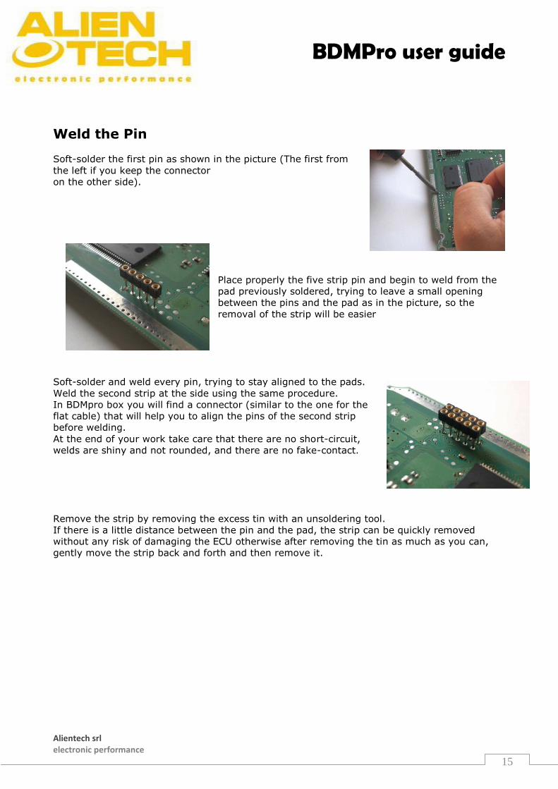
Weld the Pin
Soft-solder the first pin as shown in the picture (The first from
the left if you keep the connector
on the other side).
Place properly the five strip pin and begin to weld from the
pad previously soldered, trying to leave a small opening
between the pins and the pad as in the picture, so the
removal of the strip will be easier
Soft-solder and weld every pin, trying to stay aligned to the pads.
Weld the second strip at the side using the same procedure.
In BDMpro box you will find a connector (similar to the one for the
flat cable) that will help you to align the pins of the second strip
before welding.
At the end of your work take care that there are no short-circuit,
welds are shiny and not rounded, and there are no fake-contact.
Remove the strip by removing the excess tin with an unsoldering tool.
If there is a little distance between the pin and the pad, the strip can be quickly removed
without any risk of damaging the ECU otherwise after removing the tin as much as you can,
gently move the strip back and forth and then remove it.
BDMPro user guide
Alientech srl electronic performance
16
Alientech s.r.l. electronic performance
Sede Operativa 13039 Trino (VC) - Italy
Via Dei Cordari, 1 tel: (+39) 0161 801025
fax: (+39) 0161 828967
Per maggiori informazioni
www.alientech.to [email protected]