ali-nvr3104p, ali-nvr3108p embedded network video ... · user default password = ... of your...
TRANSCRIPT

1 ALI-NVR3104-08P_SQ 11/18/15
ALI-NVR3108P Backpanel
Internal Ethernet switch ports with PoE (8)
LAN Fan outletVideo Out (HDMI, VGA)
Audio IN/OUTUSB
Power cord connector
Power switch
Ground terminal
Item Description
VIDEO OUT (VGA, HDMI) 1 channel (HDMI/VGA), resolution: 1920 × 1080P / 60 Hz, 1600 × 1200 / 60 Hz, 1280 × 1024 / 60 Hz, 1280 × 720 / 60 Hz, 1024 × 768 / 60 Hz
AUDIO IN / OUT RCA connector for audio line input.RCA connector for audio line output. .
Power connectorALI-NVR3104P: Connect the 48 Vdc power adapter provided with the recorder to this port, and to a standard 100 ~ 240 Vac power source using the power cord provided. ALI-NVR3108P: Connect the power cord provided with the recorder to this port and to a standard 100 ~ 240 Vac power source.
ON / OFF Switch Switch for powering the recorder on or off.
GROUND Terminal for ground. Connect to earth ground before powering on the NVR.
LAN Interface 10/100/1000BASE-T Ethernet network interface
USB interface Universal Serial Bus (USB) 3.0 port for additional devices such as USB mouse and USB Hard Disk Drive (HDD).
Internal Ethernet switch ports 4 (ALI-NVR3104P) or 8 (ALI-NVR3108P) 10/100 Mbps ports for IP cameras. These ports provide Power over Ethernet (PoE).
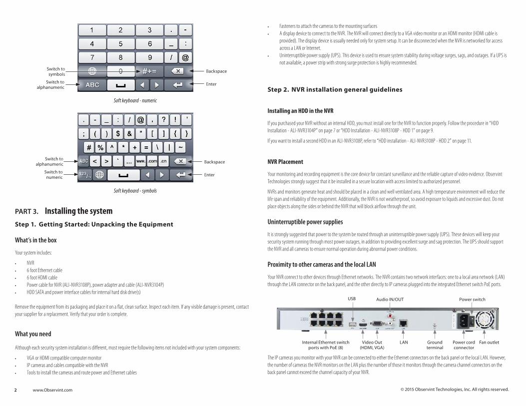
PART 2. Soft KeyboardsSoft keyboards open in the firmware when clicking on an entry field for a password, name or numerical value. Three keyboards are available: alphanumeric, numeric and symbols. You can switch to a different keyboard by clicking the button in the lower left corner. To make an entry, click the soft buttons on the keyboard to type a character string, and then click the Enter key in the lower right corner to finalize the entry and close the keyboard.
Uppercase /Lowercase Backspace
Switch to numeric Enter
Soft keyboard - alphanumeric
This quick setup guide provides instructions to initially setup and use the ALI-NVR3104P and ALI-NVR3108P network video recorders (NVRs). For additional information on the extensive capabilities of your NVR, including detailed setup and configuration instructions, please refer to the ALIBI Embedded Network Video Recorder Firmware V3.3.4 User Manual available for download from your vendor.
CONTENTSPart 1. Controls and Indicators . . . . . . . . . . . . . . . . . . . . . . . . . . . . . . . . . . . . . . . . . . . . . . . . . . . . . . . . . . . . . . . . . . . . . . . . . . . . . . . 1Part 2. Soft Keyboards . . . . . . . . . . . . . . . . . . . . . . . . . . . . . . . . . . . . . . . . . . . . . . . . . . . . . . . . . . . . . . . . . . . . . . . . . . . . . . . . . . . . . . 1Part 3. Installing the System . . . . . . . . . . . . . . . . . . . . . . . . . . . . . . . . . . . . . . . . . . . . . . . . . . . . . . . . . . . . . . . . . . . . . . . . . . . . . . . . . 2Part 4. Specifications . . . . . . . . . . . . . . . . . . . . . . . . . . . . . . . . . . . . . . . . . . . . . . . . . . . . . . . . . . . . . . . . . . . . . . . . . . . . . . . . . . . . . . . 7Part 5. HDD Installation . . . . . . . . . . . . . . . . . . . . . . . . . . . . . . . . . . . . . . . . . . . . . . . . . . . . . . . . . . . . . . . . . . . . . . . . . . . . . . . . . . . . . 7
PART 1. Controls and Indicators
Front panel (ALI-NVR3104P, ALI-NVR3108P_
Status indicators USB port
Item Function / Description
Status Indicators
POWER Indicator is green when the unit is powered on. When the unit is off, the LED is red if power is available.
HDD HDD indicator blinks red when data is being read from or written to an HDD.
TX/RX Blinks green when the network connection is functioning normally.
USB Interfaces Universal Serial Bus (USB) 2.0 port for additional USB devices such as a mouse or Hard Disk Drive (HDD).
ALI-NVR3104P Backpanel
Audio IN/OUT
Internal Ethernet switch ports with PoE (4)
LAN
Power Adapter connector
Power switch
Video Out (VGA, HDMI)
Ground terminal
USB
ALI-NVR3104P, ALI-NVR3108P Embedded Network Video Recorders Quick Setup Guide
2 www.Observint.com © 2015 Observint Technologies, Inc. All rights reserved.
• Fasteners to attach the cameras to the mounting surfaces• A display device to connect to the NVR. The NVR will connect directly to a VGA video monitor or an HDMI monitor (HDMI cable is
provided). The display device is usually needed only for system setup. It can be disconnected when the NVR is networked for access across a LAN or Internet.
• Uninterruptible power supply (UPS). This device is used to ensure system stability during voltage surges, sags, and outages. If a UPS is not available, a power strip with strong surge protection is highly recommended.
Step 2. NVR installation general guidelines
Installing an HDD in the NVR
If you purchased your NVR without an internal HDD, you must install one for the NVR to function properly. Follow the procedure in “HDD Installation - ALI-NVR3104P” on page 7 or “HDD Installation - ALI-NVR3108P - HDD 1” on page 9.
If you want to install a second HDD in an ALI-NVR3108P, refer to “HDD installation - ALI-NVR3108P - HDD 2” on page 11.
NVR Placement
Your monitoring and recording equipment is the core device for constant surveillance and the reliable capture of video evidence. Observint Technologies strongly suggest that it be installed in a secure location with access limited to authorized personnel.
NVRs and monitors generate heat and should be placed in a clean and well ventilated area. A high temperature environment will reduce the life span and reliability of the equipment. Additionally, the NVR is not weatherproof, so avoid exposure to liquids and excessive dust. Do not place objects along the sides or behind the NVR that will block airflow through the unit.
Uninterruptible power supplies
It is strongly suggested that power to the system be routed through an uninterruptible power supply (UPS). These devices will keep your security system running through most power outages, in addition to providing excellent surge and sag protection. The UPS should support the NVR and all cameras to ensure normal operation during abnormal power conditions.
Proximity to other cameras and the local LAN
Your NVR connect to other devices through Ethernet networks. The NVR contains two network interfaces: one to a local area network (LAN) through the LAN connector on the back panel, and the other directly to IP cameras plugged into the integrated Ethernet switch PoE ports.
Internal Ethernet switch ports with PoE (8)
LAN Fan outletVideo Out (HDMI, VGA)
Audio IN/OUTUSB
Power cord connector
Power switch
Ground terminal
The IP cameras you monitor with your NVR can be connected to either the Ethernet connectors on the back panel or the local LAN. However, the number of cameras the NVR monitors on the LAN plus the number of those it monitors through the camera channel connectors on the back panel cannot exceed the channel capacity of your NVR.
Switch to symbols
Backspace
Switch to alphanumeric
Enter
Soft keyboard - numeric
Switch to alphanumeric Backspace
Switch to numeric Enter
Soft keyboard - symbols
PART 3. Installing the systemStep 1. Getting Started: Unpacking the Equipment
What’s in the box
Your system includes:
• NVR • 6 foot Ethernet cable• 6 foot HDMI cable• Power cable for NVR (ALI-NVR3108P), power adapter and cable (ALI-NVR3104P)• HDD SATA and power interface cables for internal hard disk drive(s)
Remove the equipment from its packaging and place it on a flat, clean surface. Inspect each item. If any visible damage is present, contact your supplier for a replacement. Verify that your order is complete.
What you need
Although each security system installation is different, most require the following items not included with your system components:
• VGA or HDMI compatible computer monitor• IP cameras and cables compatible with the NVR• Tools to install the cameras and route power and Ethernet cables
3 www.Observint.com© 2015 Observint Technologies. All rights reserved.
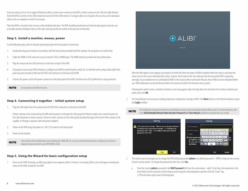
After the Alibi splash screen appears (see above), the NVR will check the status of HDDs installed within the chassis, and show the show icons on the screen indicating their status. A green check mark on the icon indicates that the associated HDD is operating normally. If you installed new (or uninitialized) HDDs in the chassis before running the Wizard, those HDDs must be initialized before use. HDD initialization can be performed within the wizard and within the firmware menu system.
Following the splash screen, a monitor resolution screen may appear. Open the drop down list and select the monitor resolution you prefer, then click OK.
2. The Setup Wizard can assist you in making important configuration settings in NVR. Click Next button on the Wizard window to open the Login window.
NOTEThe configuration settings presented in the setup Wizard can also be made and changed using the Menu system. For more information, refer to the ALIBI Embedded Network Video Recorder Firmware V3.3.4 User Manual available for download from your vendor.
3. The initial screen encourages you to change the NVR default password (admin user default password = 1111) to improve the security of your security system. To change the password at this time, click Yes.
a. Enter the current admin password in the Old Password field (see the screen above - right). To do that, click anywhere in the entry field, click the characters of the old password using the virtual keyboard, and then click the “Enter” key ( 8 )in the lower right corner of the keyboard.
If you are using Cat 5e or Cat 6 copper (Ethernet) cable to connect your cameras to the NVR, or other cameras to the LAN, the cable distance from the NVR (or switch on the LAN) should not exceed 330 feet (100 meters). If a longer cable run is required, the use of an active hardware device such as a repeater or switch is necessary.
Place the NVR in a location that is secure, well ventilated and clean. The NVR should be positioned such that the back panel connectors are accessible and the ventilation holes on the sides and top and the fan outlet on the back are not blocked.
Step 3. Install a monitor, mouse, power
For the following steps, refer to the back panel photo above for the location of connectors.
1. Install and setup your monitor in accordance with the instructions provided with the monitor. Do not power it on at this time.
2. Cable the HDMI or VGA connector to your monitor’s VGA or HDMI input. The HDMI interface provides the best performance.
3. Plug the mouse into the USB connector on the front or back of the NVR.
4. If you plan to access your NVR remotely, or configure your NVR to transmit alerts, email, etc. to external servers, plug a drop cable from your local area network (LAN) into the RJ45 LAN connector on the back of the NVR.
5. Connect the power cord to the power connector on the back panel of the NVR, and then into a UPS (preferred) or surge protector.
NOTE Do not power on the NVR at this time.
Step 4. Connecting it together – initial system setup
1. Plug the LAN cables from the cameras into the POE RJ45 connectors on the back of the NVR. If other cameras to be monitored by the NVR will network to it through the LAN, plug their Ethernet cables into a switch (router) on the LAN and power on those cameras. (Power to other cameras on the LAN may be provided through a PoE switch if the camera is PoE capable, or through a separate cable and power adapter).
2. Power on the NVR using the power on / off (I / O) switch on the back panel.
3. Power on the monitor.
NOTESome monitors have multiple inputs such including VGA ,HDMI, BNC, etc. If you are using this kind of monitor, configure your monitor to display the input connected to your NVR (HDMI or VGA).
Step 5. Using the Wizard for basic configuration setup
1. Power on the NVR. Normally, an Alibi logo splash screen appears within 2 minutes. A secondary flash screen will appear showing the status of the HDDs installed in the NVR.
4 www.Observint.com© 2015 Observint Technologies. All rights reserved.
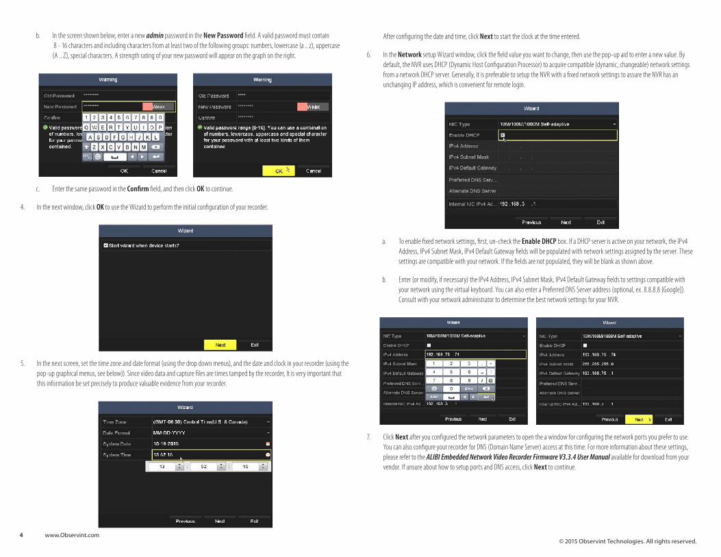
After configuring the date and time, click Next to start the clock at the time entered.
6. In the Network setup Wizard window, click the field value you want to change, then use the pop-up aid to enter a new value. By default, the NVR uses DHCP (Dynamic Host Configuration Processor) to acquire compatible (dynamic, changeable) network settings from a network DHCP server. Generally, it is preferable to setup the NVR with a fixed network settings to assure the NVR has an unchanging IP address, which is convenient for remote login.
a. To enable fixed network settings, first, un-check the Enable DHCP box. If a DHCP server is active on your network, the IPv4 Address, IPv4 Subnet Mask, IPv4 Default Gateway fields will be populated with network settings assigned by the server. These settings are compatible with your network. If the fields are not populated, they will be blank as shown above.
b. Enter (or modify, if necessary) the IPv4 Address, IPv4 Subnet Mask, IPv4 Default Gateway fields to settings compatible with your network using the virtual keyboard. You can also enter a Preferred DNS Server address (optional, ex. 8.8.8.8 {Google]). Consult with your network administrator to determine the best network settings for your NVR.
7. Click Next after you configured the network parameters to open the a window for configuring the network ports you prefer to use. You can also configure your recorder for DNS (Domain Name Server) access at this time. For more information about these settings, please refer to the ALIBI Embedded Network Video Recorder Firmware V3.3.4 User Manual available for download from your vendor. If unsure about how to setup ports and DNS access, click Next to continue.
b. In the screen shown below, enter a new admin password in the New Password field. A valid password must contain 8 - 16 characters and including characters from at least two of the following groups: numbers, lowercase (a .. z), uppercase (A .. Z), special characters. A strength rating of your new password will appear on the graph on the right.
c. Enter the same password in the Confirm field, and then click OK to continue.
4. In the next window, click OK to use the Wizard to perform the initial configuration of your recorder.
5. In the next screen, set the time zone and date format (using the drop down menus), and the date and clock in your recorder (using the pop-up graphical menus, see below)). Since video data and capture files are times tamped by the recorder, It is very important that this information be set precisely to produce valuable evidence from your recorder.
5 www.Observint.com
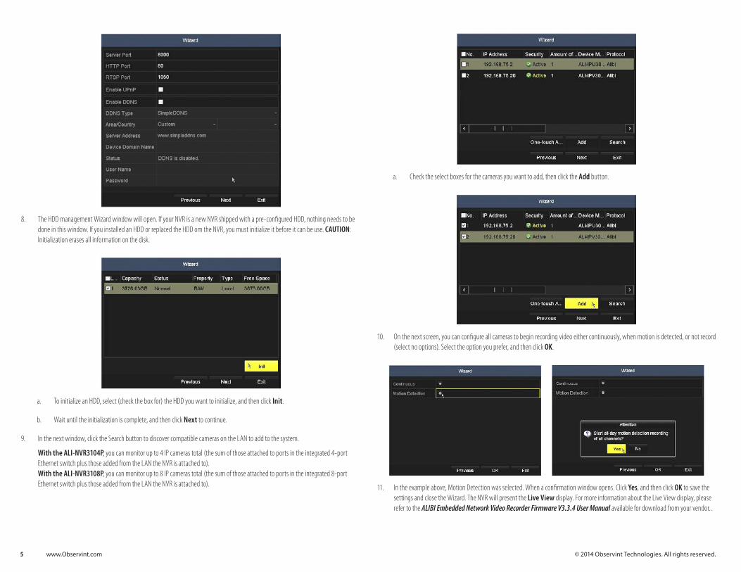
a. Check the select boxes for the cameras you want to add, then click the Add button.
10. On the next screen, you can configure all cameras to begin recording video either continuously, when motion is detected, or not record (select no options). Select the option you prefer, and then click OK.
11. In the example above, Motion Detection was selected. When a confirmation window opens. Click Yes, and then click OK to save the settings and close the Wizard. The NVR will present the Live View display. For more information about the Live View display, please refer to the ALIBI Embedded Network Video Recorder Firmware V3.3.4 User Manual available for download from your vendor..
8. The HDD management Wizard window will open. If your NVR is a new NVR shipped with a pre-configured HDD, nothing needs to be done in this window. If you installed an HDD or replaced the HDD om the NVR, you must initialize it before it can be use. CAUTION: Initialization erases all information on the disk.
a. To initialize an HDD, select (check the box for) the HDD you want to initialize, and then click Init.
b. Wait until the initialization is complete, and then click Next to continue.
9. In the next window, click the Search button to discover compatible cameras on the LAN to add to the system.
With the ALI-NVR3104P, you can monitor up to 4 IP cameras total (the sum of those attached to ports in the integrated 4-port Ethernet switch plus those added from the LAN the NVR is attached to). With the ALI-NVR3108P, you can monitor up to 8 IP cameras total (the sum of those attached to ports in the integrated 8-port Ethernet switch plus those added from the LAN the NVR is attached to).
© 2014 Observint Technologies. All rights reserved.
6 www.Observint.com© 2015 Observint Technologies. All rights reserved.
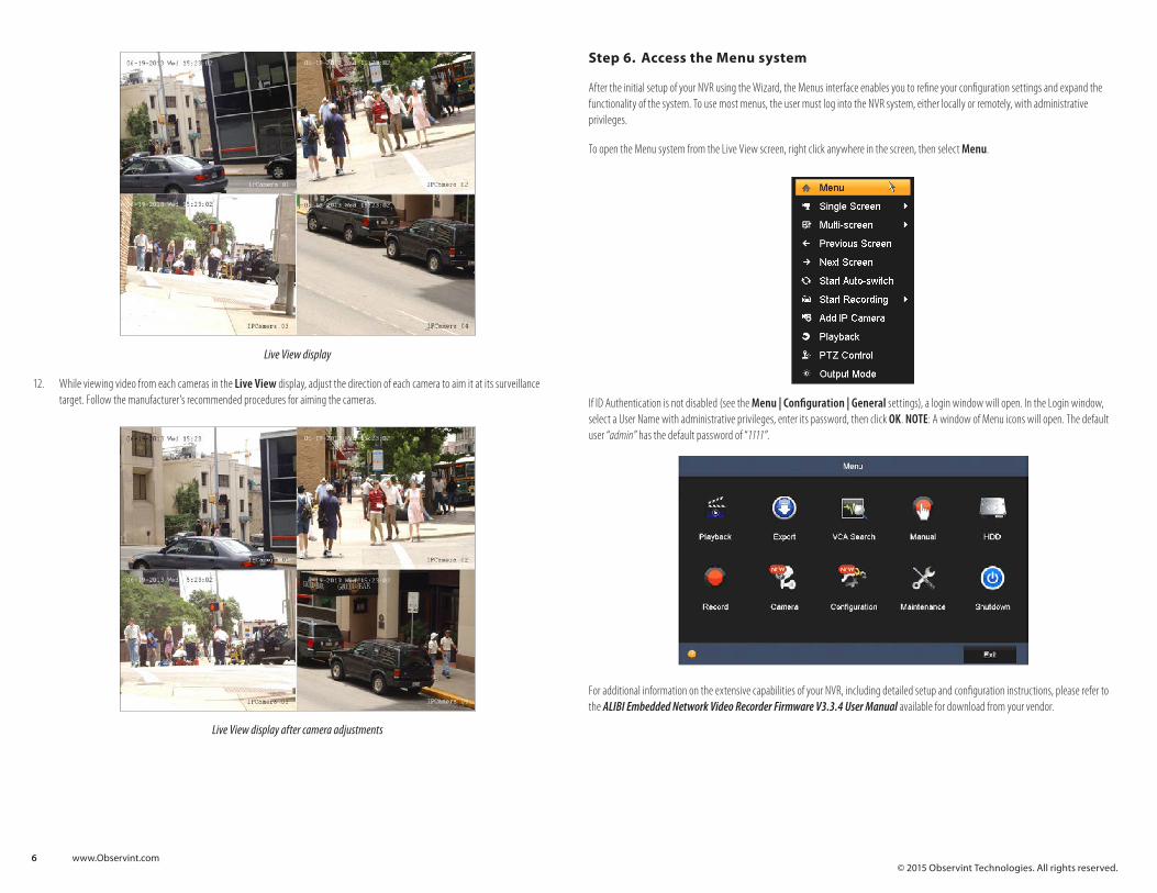
Step 6. Access the Menu system
After the initial setup of your NVR using the Wizard, the Menus interface enables you to refine your configuration settings and expand the functionality of the system. To use most menus, the user must log into the NVR system, either locally or remotely, with administrative privileges.
To open the Menu system from the Live View screen, right click anywhere in the screen, then select Menu.
If ID Authentication is not disabled (see the Menu | Configuration | General settings), a login window will open. In the Login window, select a User Name with administrative privileges, enter its password, then click OK. NOTE: A window of Menu icons will open. The default user “admin” has the default password of “1111”.
For additional information on the extensive capabilities of your NVR, including detailed setup and configuration instructions, please refer to the ALIBI Embedded Network Video Recorder Firmware V3.3.4 User Manual available for download from your vendor.
Live View display
12. While viewing video from each cameras in the Live View display, adjust the direction of each camera to aim it at its surveillance target. Follow the manufacturer’s recommended procedures for aiming the cameras.
Live View display after camera adjustments

7 www.Observint.com© 2015 Observint Technologies. All rights reserved.
Remote Client System Requirements
Operating System Microsoft Windows XP, Vista, 7, 8, 10 (32-bit and 64-bit version) / Linux 2.6+ / Apple MacOS X 10.5 (Intel x86 only), 10.6 and 10.7
Web Browser Microsoft Internet Explorer 8.0, 9.0, 10, and 11 (32-bit version), Mozilla Firefox 13 and higher and 3.6, Safari 5 and higher
Software Requirements Web Component Installation
Mobile Client OS Platform iOS, Android (Alibi Witness)
Supplied Accessories
CD ROM (User’s Guide, Installation Tools)
Quick Installation Guide
USB Mouse
Hard Drive Cables and Screws
48Vdc Power Supply , 110 Vac Power Cord 110 Vac Power Cord
PART 5. HDD InstallationThe following procedures illustrate hard disk drive (HDD) installation in NVR without an HDD, and installation of a second HDD. If you purchased your NVR without a HDD, or you want to replace the HDD installed in your NVR, use this procedure as a guideline.
NVR compatible HDDs
For the best performance of your system, install only a high-reliability security grade HDD, such as Western Digital® Purple series or GreenPower™ series HDD. Security grade HDDs are designed to stream video efficiently and have a very low failure rate.
The NVR can accommodate one HDD (ALI-NVR3104P) or two HDDs (ALI-NVR3108P), each with a capacity up to 6TB.
HDD Installation - ALI-NVR3104P
Cables and screws needed to install the HDD are provided.
CAUTION
Follow recommended electrostatic discharge (ESD) guidelines while performing this procedure. Install the HDD in a static-free environment, wearing a certified ESD wrist strap. If a static free environment and ESD wrist strap is not available, touch the bare metal of the DVR chassis frequently when installing the drive to dissipate the static charge naturally generated on your skin and clothing and avoid touching electronic components.
1. Power off the DVR, if necessary, then disconnect the power adapter and all other cables from the recorder.
2. Remove the top cover from the DVR by removing the six cover screws. Two cover screws are located on each side, and two are located on the back. See the drawing below. Save the screws for use later.
PART 4. Specifications
Model ALI-NVR3104P ALI-NVR3108P
Number of Channels Supported 4 8
Compression Format H.264
Recording Performance 40 Mbps max 80 Mbps max
Remote Viewing Output Capacity 80 Mbps max
Supported Frame Rate per Channel Main stream: Up to 60 fps, Sub-stream: Up to 60 fps
Recording Type Continuous, Schedule, Event, Motion Detection, VCA, POS
Supported IP Camera Resolution 6MP / 5MP / 3MP / 1080p / UXGA / 720p / VGA / 4CIF / DCIF / 2CIF / CIF / QCIF
Supported Playback Resolution 6MP / 5MP / 3MP / 1080p / UXGA / 720p / VGA / 4CIF / DCIF / 2CIF / CIF / QCIF
Synchronous Playback 4-ch @ 1080P 8-ch @ 720P, 6-ch @ 1080P
Video Output VGA, HDMI
Video Output Formats 1 channel (HDMI / VGA), resolution: 1920 × 1080P / 60 Hz, 1600 × 1200/60 Hz, 1280 × 1024 / 60 Hz, 1280 × 720 / 60 Hz, 1024 × 768 / 60 Hz”
Two-Way Audio Input 1-ch, RCA (2.0 Vp-p, 1 kΩ)
Audio Output 1-ch, RCA (Linear, 1 kΩ)
Export Formats .MP4
Ethernet 1x Gigabit RJ-45 self-adaptive Ethernet interface, 4 independent 10 /100 Mbps PoE Ethernet interfaces
1x Gigabit RJ-45 self-adaptive Ethernet interface, 8 independent 10 /100 Mbps PoE Ethernet interfaces
Power Over Ethernet Max Power: 50 W Supported Standards: 802.3af and 802.3at
Max Power: 120 W Supported Standards: 802.3af and 802.3at
USB 1x USB 2.0, 1x USB 3.0 1x USB 2.0, 1x USB 3.0
Hard Drive Interface 1x SATA 2x SATA
Hard Drive Capatcity 1x HDDs, up to 6TB capacity 2x HDDs max, up to 6TB capacity each
Alarm Input Camera Dependent
Alarm Output Camera Dependent
Operating System Embedded Linux
Security Password Protection
Protocols IPv4, TCP/IP, UDP, HTTP, UPnP, RTSP/RTP/RTCP, SMTP, FTP, DHCP, NTP, DNS, ONVIF, HTTP multipart
Power Requirements 48 Vdc 110-240 Vac @ 3.0 A
Power Consumption ≤ 10W (without HDD) ≤ 10 W (without HDD)
Weight 2.2 lbs. (without HDD) 2.5 lbs. (without HDD)
Dimensions (in.) 12.4” W × 9.1” D × 1.8” H 17.4” W × 11.4” D × 1.8” H
Operating Temperature 14°F ~ 131°F
Color / Material Black
Material Aluminum
Approvals CE, FCC, RoHS
8 www.Observint.com© 2015 Observint Technologies. All rights reserved.
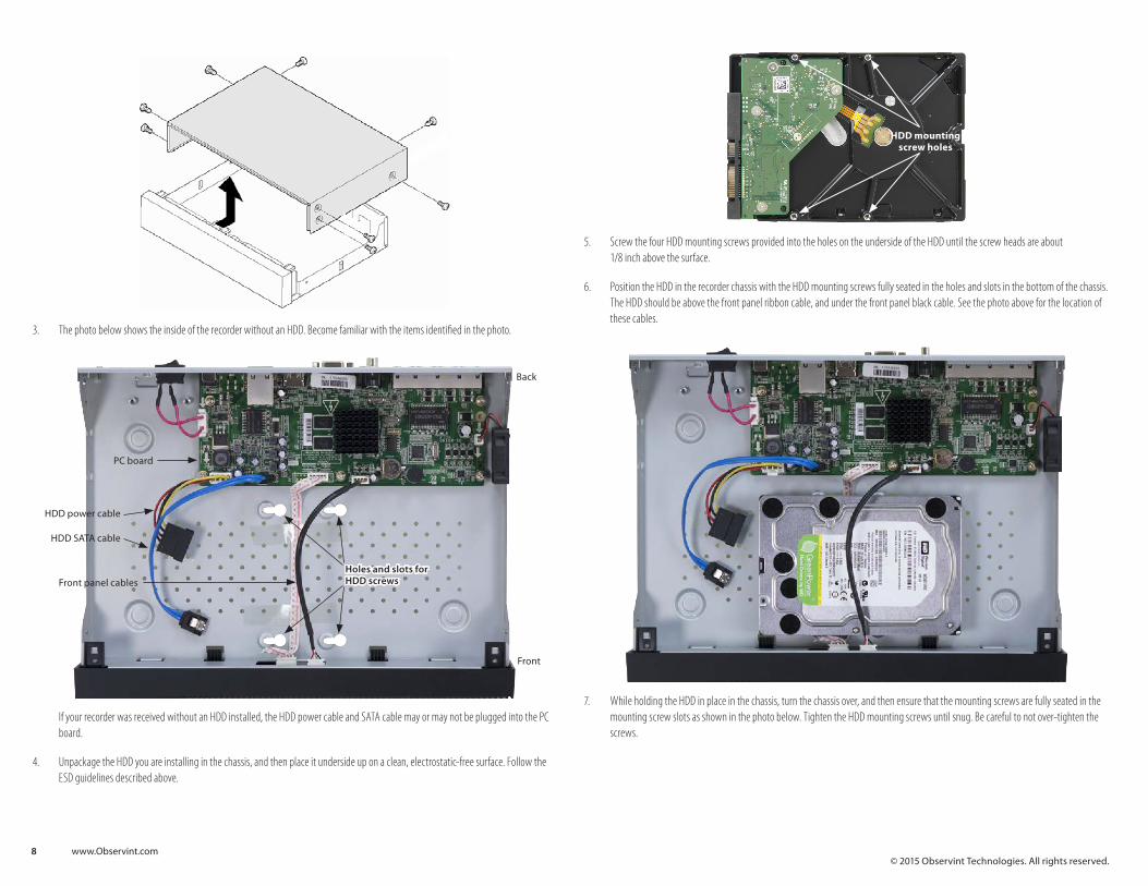
HDD mounting screw holes
5. Screw the four HDD mounting screws provided into the holes on the underside of the HDD until the screw heads are about 1/8 inch above the surface.
6. Position the HDD in the recorder chassis with the HDD mounting screws fully seated in the holes and slots in the bottom of the chassis. The HDD should be above the front panel ribbon cable, and under the front panel black cable. See the photo above for the location of these cables.
7. While holding the HDD in place in the chassis, turn the chassis over, and then ensure that the mounting screws are fully seated in the mounting screw slots as shown in the photo below. Tighten the HDD mounting screws until snug. Be careful to not over-tighten the screws.
3. The photo below shows the inside of the recorder without an HDD. Become familiar with the items identified in the photo.
Holes and slots for HDD screws
HDD power cable
HDD SATA cable
Front panel cables
PC board
Back
Front
If your recorder was received without an HDD installed, the HDD power cable and SATA cable may or may not be plugged into the PC board.
4. Unpackage the HDD you are installing in the chassis, and then place it underside up on a clean, electrostatic-free surface. Follow the ESD guidelines described above.

9 www.Observint.com© 2015 Observint Technologies. All rights reserved.
11. Initialize (Init) the HDD when you setup the NVR using Wizard.
HDD Installation - ALI-NVR3108P - HDD 1
The recorder will accommodate one or two internal HDDs. If your recorder doesn’t have an HDD installed, use this procedure to install the first HDD. The HDD mounting screws and HDD cables are provided with your recorder.
CAUTION
Follow recommended electrostatic discharge (ESD) guidelines while performing this procedure. Install the HDD in a static-free environment, wearing a certified ESD wrist strap. If a static free environment and ESD wrist strap is not available, touch the bare metal of the DVR chassis frequently when installing the drive to dissipate the static charge naturally generated on your skin and clothing and avoid touching electronic components.
1. Disconnect all cables from the recorder, and then set the recorder on a clean, static free surface, top up.
2. Remove the top cover from the recorder by removing the cover screws on the back of the chassis, and each side.
3. Orient the chassis as shown in the picture below. Become familiar with the locations of the HDD mounting screws for HDD 1 (initial HDD) and HDD 2 (second HDD), and the location of the HDD 1 SATA connector on the PC board.
8. Turn the chassis over, and then attach the HDD power cable and SATA cable to the mating connectors on the HDD and PC board. These connectors must be fully seated.
9. Reinstall the DVR cover using the cover using the screws removed earlier.
10. During the DVR initialization, follow the options in the Wizard to initialize/reformat the HDD. You can also initialize the HDD using the Menu | HDD feature. For more information, refer to the ALIBI Embedded Network Video Recorder Firmware V3.3.4 User Manual available for download from your vendor.

10 www.Observint.com© 2015 Observint Technologies. All rights reserved.
7. Position the HDD in HDD 1 bay under the front panel cables such that the HDD cable connectors are toward the middle of the chassis and the HDD mounting screws are fully seated in the mounting screw slots.
8. While holding the HDD in place, carefully turn over the chassis with the HDD and then tighten the mounting screws to secure the HDD. Be careful not to overtighten the screws.
HDD 1 mounting screws
9. Turn the chassis over so the top is up.
10. Attach the HDD SATA cable to the HDD 1 SATA cable connector on the PC board, and then to the SATA connector on the HDD. When the connector is fully seated, it clips into place.
11. Attach the HDD power cable to the power cable connector on the HDD.
Back PC boardHDD 1 SATA cable connector
HDD 2 SATA cable connector
HDD 1 bay HDD 2 bay
HDD power cables (2)
Front panel cables (2)
Slots for HDD mounting
screws (2 x 4)
4. Remove the tape securing the front panel cables are taped to the bottom of the chassis. Usually two strips of tape are used to hold down the cables.
5. Unpackage the HDD. In the photo below, note the location of the HDD mounting screw holes on the underside of the HDD. Also shown are the SATA and Power cable connectors.
SATA cable connector
Power cable connector
HDD mounting screw holes
6. Screw the four HDD mounting screws into the mounting screw holes until the screw heads are about 1/8 inch from the surface bottom of the HDD.
CAUTION
Follow recommended electrostatic discharge (ESD) guidelines while performing this procedure. Install the HDD in a static-free environment, wearing a certified ESD wrist strap. If a static free environment and ESD wrist strap is not available, touch the bare metal of the DVR chassis frequently when installing the drive to dissipate the static charge naturally generated on your skin and clothing and avoid touching electronic components.

11 www.Observint.com© 2015 Observint Technologies. All rights reserved.
3. Orient the chassis as shown in the picture below. Become familiar with the locations of the HDD mounting screws for HDD 2 (second HDD), and the HDD 2 SATA PC board connector.
Back PC boardHDD 1 SATA cable connector
HDD 2 SATA cable connector
HDD 1 bay HDD 2 bay
HDD 2 power cable
Front panel cables (2)
Slots for HDD mounting
screws (2 x 4)
4. Unpackage the HDD. In the photo below, note the location of the HDD mounting screw holes on the underside of the HDD. Also shown are the SATA and Power cable connectors.
12. If you are not installing a second HDD in the chassis, reinstall the chassis cover.
13. Initialize (Init) the HDD when you setup the NVR using Wizard.
HDD installation - ALI-NVR3108P - HDD 2
Installing a second HDD in the chassis is very similar to installation of the first HDD (HDD 1). The differences include the location where the HDD is secured, SATA cable connection on the PC board, and concern about the routing of the front panel cables. If you didn’t install the first HDD in the chassis, become familiar with the procedure in “HDD Installation - ALI-NVR3108P - HDD 1” on page 9.
CAUTION
Follow recommended electrostatic discharge (ESD) guidelines while performing this procedure. Install the HDD in a static-free environment, wearing a certified ESD wrist strap. If a static free environment and ESD wrist strap is not available, touch the bare metal of the DVR chassis frequently when installing the drive to dissipate the static charge naturally generated on your skin and clothing and avoid touching electronic components.
1. Disconnect all cables from the recorder, and then set the recorder on a clean, static free surface, top up.
2. Remove the top cover from the recorder by removing the cover screws on the back of the chassis, and each side.

12 www.Observint.com© 2015 Observint Technologies. All rights reserved.
8. Turn the chassis over so the top is up.
9. Attach the HDD SATA cable to the HDD 2 SATA cable connector on the PC board, and then to the SATA connector on the HDD. When the connector is fully seated, it snaps into place.
10. Attach the HDD power cable to the power cable connector on the HDD.
11. Reinstall the chassis cover.
12. Initialize the HDD. Refer to the ALIBI Embedded Network Video Recorder Firmware V3.3.4 User Manual available for download from your vendor.
SATA cable connector
Power cable connector
HDD mounting screw holes
5. Screw the four HDD mounting screws into the mounting screw holes until the screw heads are about 1/8 inch from the surface bottom of the HDD.
CAUTION
Follow recommended electrostatic discharge (ESD) guidelines while performing this procedure. Install the HDD in a static-free environment, wearing a certified ESD wrist strap. If a static free environment and ESD wrist strap is not available, touch the bare metal of the DVR chassis frequently when installing the drive to dissipate the static charge naturally generated on your skin and clothing and avoid touching electronic components.
6. Position the HDD in HDD 2 bay such that the HDD cable connectors are toward the middle of the chassis and the HDD mounting screws are fully seated in the mounting screw slots.
7. While holding the HDD in place, carefully turn over the chassis with the HDD and then tighten the mounting screws to secure the HDD. Be careful not to overtighten the screws.
HDD 2 mounting screws