alex k darc - frontier homepage powered by...
TRANSCRIPT

PHOTOCLASS/ECE580/ARCs/ARCS.ppt Brainerd
1
Anti-Reflective Coatings
• Reflection• Anti-reflection Principles• Swing Curves• Reflectivity curve• Top ARCs TARC• Bottom ARCs BARC• Organic BARC• Inorganic DARCs
PHOTOCLASS/ECE580/ARCs/ARCS.ppt Brainerd
2
Anti-Reflective Coatings: Web sites
• http://www.newport.com/store/product.asp?lone=Optics<wo=Technical+Reference<hree=Optics+Formulas&lfour=&id=3877
• http://webug.physics.uiuc.edu/courses/phys371/RightFrame.htm• http://dustbunny.physics.indiana.edu/~dzierba/P360n/KPAD/Exps/Fres
nel/fresnelnote.pdf• http://www.hep.princeton.edu/~p104/lectures/lecture09.pdf• http://www.mellesgriot.com/pdf/005.4-5.7.pdf• http://www.mellesgriot.com/glossary/wordlist/glossarylist.asp?l=b

PHOTOCLASS/ECE580/ARCs/ARCS.ppt Brainerd
3
Anti-Reflective Coatingshttp://hyperphysics.phy-astr.gsu.edu/hbase/phyopt/reflectcon.html#c1
• Reflection theory

PHOTOCLASS/ECE580/ARCs/ARCS.ppt Brainerd
4
Anti-Reflective Coatingshttp://hyperphysics.phy-astr.gsu.edu/hbase/phyopt/reflectcon.html#c1
• Reflection theory

PHOTOCLASS/ECE580/ARCs/ARCS.ppt Brainerd
5
Anti-Reflective Coatingshttp://hyperphysics.phy-astr.gsu.edu/hbase/phyopt/reflectcon.html#c1
• Reflection theory

PHOTOCLASS/ECE580/ARCs/ARCS.ppt Brainerd
6
Anti-Reflective CoatingsClariant Antireflective Coatings Lecture Notes
• Reflection theoryAbsorption and reflection phenomena can be treated equivalently if the refractive index is written as a complex number:
ñ = n - i kwhere
n = Re (ñ); k = - Im(ñ) =
The real part n of the refractive index is also frequently called the “refractive index”. The imaginary part k is related to the absorbance αof the material by the equation above.The above convention for the sign of k (k > 0) is called the “optical convention”.
α λ4

PHOTOCLASS/ECE580/ARCs/ARCS.ppt Brainerd
7
Anti-Reflective Coatings
• Reflection theory:• Condition: Beam incident normal to surface in a medium with no
refractive index and reflective substrate with nc.
• REFLECTED wave amplitude A = Eo ρ (Eo = electric field )• Coefficient of reflection: ρ = (no - nc)/ (no + nc)• If ρ is negative there is a 180o phase shift.• Then reflectivity R = % = Ir/Io = ρ 2 = [(no - nc)/ (no + nc)]2
• where Ir = reflected intensity, Io = incident intensity• Relative Amplitude = (1- no / nc)/ (1 + no / nc)• Relative reflected intensity = A2 ( note intensity = square of electric
field)

PHOTOCLASS/ECE580/ARCs/ARCS.ppt Brainerd
8
Anti-Reflective Coatings
• External Reflection at a dielectric boundary:• Fresnel’s law of reflection for the s and p polarized components:
• Ordinary and extraordinary rays:• o-ray (oordinary ray): polarized parallel to plane of incidence. Also termed p-
polarization.• e-ray (extraordinary ray): polarized perpendicular to plane of incidence. Also
termed s-polarization.
Non-normal Incidence: o = angle of reflection angle and c = angle of refraction

PHOTOCLASS/ECE580/ARCs/ARCS.ppt Brainerd
9
Anti-Reflective Coatings• External Reflection at a dielectric boundary:• Fresnel’s law of reflection for the s and p polarized components:
• Non-normal Incidence: o = angle of reflection angle and c = angle of refraction
• r = refection (reflected waves)
• rs = (nocosθo -nccosθc)/(nocosθo + nccosθc) ; rp = (nccos θo -nocosθc)/nccosθo + nocosθc)
• c = transmission ( refracted waves)
• ts = 2nocosθo/(nocosθo + nccosθc) ; cp = 2nocosθo/(nccosθo + nocosθc)
•

PHOTOCLASS/ECE580/ARCs/ARCS.ppt Brainerd
10
Anti-Reflective Coatings• External Reflection at a dielectric boundary:• Fresnel’s law of reflection for the s and p polarized components:
• Non-normal Incidence: o = angle of reflection angle and c = angle of refraction
• Reflectivity in %:
• for Normal incidence Fresnel’s law becomes: R = ρ 2 = [(no - nc)/ (no + nc)]2
• In air no = 1.00 and at normal incidence Fresnels’s law reduces to
• % Reflectance R = ρ 2 Rp = Rs = ρ 2 = [(n-1)/(n+1)]2 for glass (n=1.50 , then R = 0.04 = 4% at each surface!
PHOTOCLASS/ECE580/ARCs/ARCS.ppt Brainerd
11
Anti-Reflective CoatingsIMAGE: http://www.hep.princeton.edu/~p104/lectures/lecture09.pdf
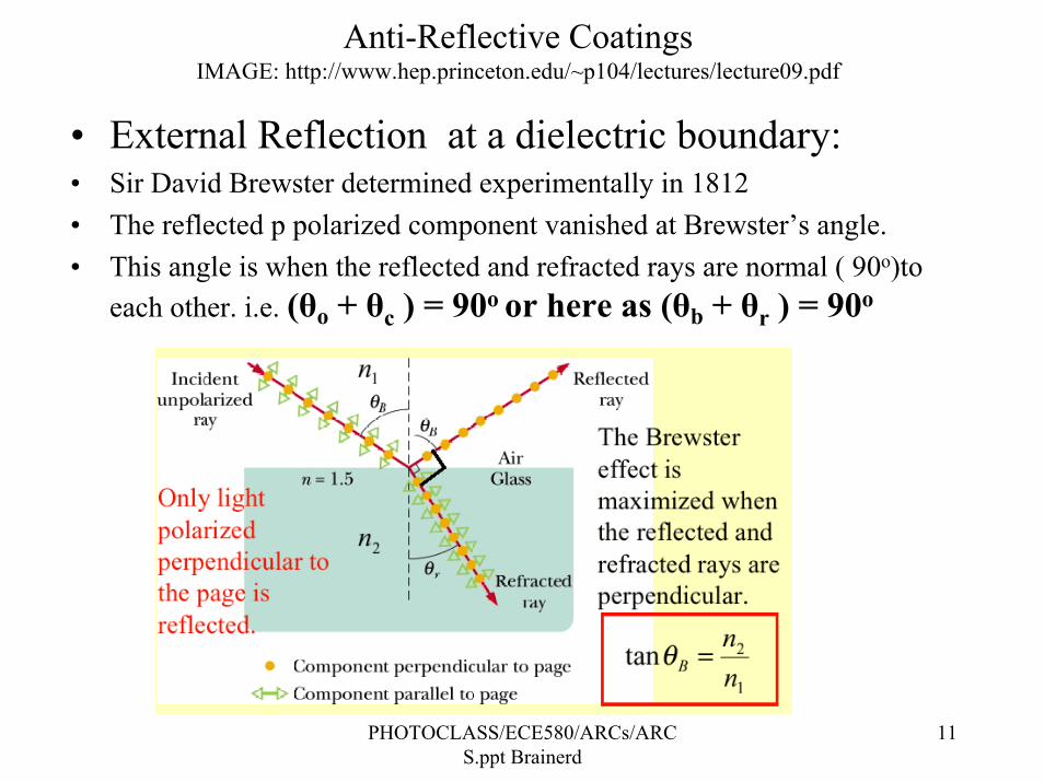
• External Reflection at a dielectric boundary:• Sir David Brewster determined experimentally in 1812• The reflected p polarized component vanished at Brewster’s angle.• This angle is when the reflected and refracted rays are normal ( 90o)to
each other. i.e. (θo + θc ) = 90o or here as (θb + θr ) = 90o

PHOTOCLASS/ECE580/ARCs/ARCS.ppt Brainerd
12
Anti-Reflective CoatingsIMAGE: http://www.mellesgriot.com/pdf/005.4-5.7.pdf
• Reflection at a dielectric boundary:
• KEY IDEA:
• The phase of the light wave reflected from a rare to dense medium is shifted by 180o (π).
• This means a beam in a medium with a lower refractive index than the reflecting medium
• I.e. no < nc
Coefficient of reflection: ρ = (no - nc)/ (no + nc)If ρ is negative there is a 180o phase shift. ( normal incidence)
PHOTOCLASS/ECE580/ARCs/ARCS.ppt Brainerd
13
Anti-Reflective Coatingsimage: http://www.mellesgriot.com/pdf/005.8-5.11.pdf
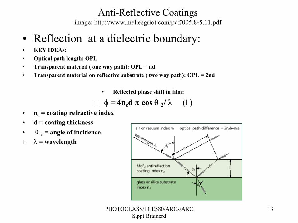
• Reflection at a dielectric boundary:• KEY IDEAs:• Optical path length: OPL• Transparent material ( one way path): OPL = nd• Transparent material on reflective substrate ( two way path): OPL = 2nd
• Reflected phase shift in film:
φ = 4ncd π cos θ 2/ λ (1)• nc = coating refractive index• d = coating thickness• θ 2 = angle of incidence
λ = wavelength

PHOTOCLASS/ECE580/ARCs/ARCS.ppt Brainerd
14
Anti-Reflective Coatingshttp://hyperphysics.phy-astr.gsu.edu/hbase/phyopt/reflectcon.html#c1
• Thin film interference:• Example: Oil on water

PHOTOCLASS/ECE580/ARCs/ARCS.ppt Brainerd
15
Anti-Reflective Coatingshttp://hyperphysics.phy-astr.gsu.edu/hbase/phyopt/reflectcon.html#c1
• Thin film interference

PHOTOCLASS/ECE580/ARCs/ARCS.ppt Brainerd
16
Anti-Reflective Coatingshttp://hyperphysics.phy-astr.gsu.edu/hbase/phyopt/interf.html#c2

PHOTOCLASS/ECE580/ARCs/ARCS.ppt Brainerd
17
Anti-Reflective Coatingsimage: http://www.mellesgriot.com/pdf/005.8-5.11.pdf
• Anti - Reflection Coating (ARC):• ARC Primciple:
• If the phase shift between the two reflected wavefronts r1 and r2 is 180o (π) as adjusted by the coating thickness and refractive index, they will interfere destructively and the overall reflected intensity is a minimum.
• If these two reflected wavefronts r1 and r2 also have equal amplitudes ( intensity), then the overall reflected intensity will be zero.
• Therefore the requirement for a “perfect” single coating Anti-reflection film for the cancellation of the reflectedwavefront is:
• 1. Refected wavefronts are 180 out of phase.
• 2. Refected wavefronts have same intensity ( amplitude).
r1r2

PHOTOCLASS/ECE580/ARCs/ARCS.ppt Brainerd
18
Anti-Reflective Coatingsimage: http://www.mellesgriot.com/pdf/005.8-5.11.pdf
• Anti - Reflection Coating (ARC):• Simple math for calculation of Anti-reflective coating ( TARC or
BARC) thickness and refractive index.
• SIMPLE CASE Assume non-absorbing film ( no k extinction coefficient), un-polarized coherent light, and normal incidence.
• A. ARC Phase condition: require a 180o (π) phase shift to cancel reflections. Find ncd (optical thickness 2 passes) where
• Reflected phase shift: φ = π = 4ncd π cos θ 2/ λ (1)• then ncd = λ / 4cos θ 2• then let θ 2 = 0• then Optical thickness (OPL) = ncd = λ / (4cos θ 2 )= λ /
(4cos 0) = λ / 4• So a film thickness d of λ / 4nc satisfies the 180o
(π) phase shift!
PHOTOCLASS/ECE580/ARCs/ARCS.ppt Brainerd
19
Anti-Reflective Coatingsimage: http://www.mellesgriot.com/pdf/005.8-5.11.pdf
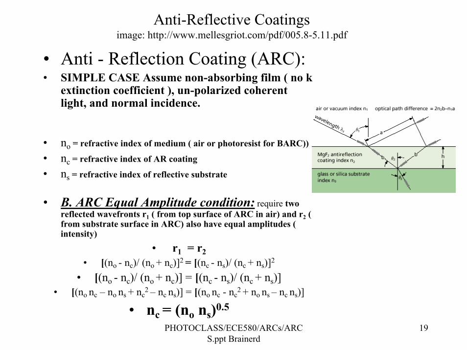
• Anti - Reflection Coating (ARC):• SIMPLE CASE Assume non-absorbing film ( no k
extinction coefficient ), un-polarized coherent light, and normal incidence.
• no = refractive index of medium ( air or photoresist for BARC))
• nc = refractive index of AR coating
• ns = refractive index of reflective substrate
• B. ARC Equal Amplitude condition: require two reflected wavefronts r1 ( from top surface of ARC in air) and r2 ( from substrate surface in ARC) also have equal amplitudes ( intensity)
• r1 = r2• [(no - nc)/ (no + nc)]2 = [(nc - ns)/ (nc + ns)]2
• [(no - nc)/ (no + nc)] = [(nc - ns)/ (nc + ns)]• [(no nc – no ns + nc
2 – nc ns)] = [(no nc - nc2 + no ns – nc ns)]
• nc = (no ns)0.5

PHOTOCLASS/ECE580/ARCs/ARCS.ppt Brainerd
20
Anti-Reflective Coatingshttp://physics.bu.edu/~duffy/PY106/Diffraction.html
• ARC: Requires 2 conditions:• Waves are 180o out of phase and same amplitude

PHOTOCLASS/ECE580/ARCs/ARCS.ppt Brainerd
21
Anti-Reflective Coatings
Key photoresist CD variation Effects:
Swing Curve: Interference of r1 and r12
Standing Waves: Interference of i1 and r1
Reflective substrate ns
Medium no
i1
r1
r12

PHOTOCLASS/ECE580/ARCs/ARCS.ppt Brainerd
22
Anti-Reflective Coatings
Key photoresist CD variation Effects ( Swing curve and standing waves) reduced with Anti-reflective coatings:
BARC: Cancel r1 with interference with r2
TARC: Cancel r12 with interference with r22
Substrate ns
Medium no
i1 r1
r12
BARC nc
r22r2
TARC ntop

PHOTOCLASS/ECE580/ARCs/ARCS.ppt Brainerd
23
Anti-Reflective CoatingsSpecific films n and k
Material Wavelength n kSilicon 365 6.522 2.705
248 1.57 3.565Aluminum 365 0.407 4.43
248 0.19 2.94BARLi 365 1.653 0.3325
248 1.686 0.255AZ7511 (i- line) 365 1.716 0.025
DX981 248 1.76 0.0045

PHOTOCLASS/ECE580/ARCs/ARCS.ppt Brainerd
24
Anti-Reflective CoatingsSwing curve % CD deviation from Target
Photoresist thickness microns

PHOTOCLASS/ECE580/ARCs/ARCS.ppt Brainerd
25
Anti-Reflective CoatingsSwing curve Top Antireflective coating: Blue
curve AZ Aquatar: @ 365nm
60
70
80
90
100
110
120
0 .8 0 .85 0 .9 0 .95 1 1 .05 1 .1 1 .15 1 .2 1 .25
Ener
gy [m
J/cm
2 ]
Photoresist Thickness Microns

PHOTOCLASS/ECE580/ARCs/ARCS.ppt Brainerd
26
Anti-Reflective CoatingsSwing curves
The action of bottom and top antireflective layers on the swing
amplitude S is described in good approximation by Brunner’s formula
R eb t- αdS R= 4
where
Rb: reflectivity at the resist/substrate interface – reduced by bottom antireflective coats BARC
Rt: reflectivity at the resist/air interface - reduced by top antireflective coatings TARC
α: resist absorbance - increased by dye addition (Dill’s B parameter)

PHOTOCLASS/ECE580/ARCs/ARCS.ppt Brainerd
27
Anti-Reflective CoatingsSwing curves
On anti-reflective coatings, the swing curves can be so shallow that the conventional definition of “swing curve ratio”
can be misleading. In the example below, one would still find a swing ratio of nearly 9% in the limit of the periodic part going to zero. For shallow swing curves, this definition is best replaced with that of the amplitude of the periodic part. The predictions made by Brunner’s formula do not include the linear part of the swing curve, and can therefore only be compared to swing amplitudes.
−S
I I
Imid
= max min

PHOTOCLASS/ECE580/ARCs/ARCS.ppt Brainerd
28
Anti-Reflective CoatingsReflectivity Curve for a BARC @ 365 nm
0
0.1
0.2
0.3
0.4
0.5
0.6
0.7
0.8
0.9
1
0 0.1 0.2 0.3 0.4 0.5
bottom coat thickness [µm]
Ref
lect
ivity
[rel
ativ
e to
Si]
R into resistR into air

PHOTOCLASS/ECE580/ARCs/ARCS.ppt Brainerd
29
Anti-Reflective CoatingsReflectivity Curve for a BARC @ 365 nm
0
0.1
0.2
0.3
0.4
0.5
0.6
0.7
0.8
0.9
1
0 0.1 0.2 0.3 0.4 0.5
bottom coat thickness [µm]
Ref
lect
ivity
[rel
ativ
e to
Si]
R into resistR into air
6065707580859095
100105110
0.8 0.85 0.9 0.95 1resist thickness [µm]
Dose
toCle
a r[m
J/cm²
]
Dose
toCl
ear[m
J/cm²
]0 nm (bare silicon)
6065707580859095
100105110
0.8 0.85 0.9 0.95 1resist thickness [µm]
Dose
toCl
ear[
mJ/cm
² ]
90 nm
6065707580859095
100105110
0.8 0.85 0.9 0.95 1resist thickness [µm]
Dose
toC l
ear[
mJ/c
m²]
190 nm

PHOTOCLASS/ECE580/ARCs/ARCS.ppt Brainerd
30
Top Anti-Reflective CoatingsTARC
* TARC Top Antireflective coating: Spin on top of Photoresist coating
* IBM Invention again!! Only 2 companies manufacture!
* Easy Process Integration: very effective for reduced swing curve
* REQUIREMENTS:
* No intermixing with photoresist:
* AZ Aquatar III-45 (MSDS): Fluoroalkylsulfonic Acid salt <5%; Water > 95%
* JSR NFC-540 ( MSDS): Fluoroacrylic polymer 1-10%;Anionic Surfactant 0.1-1%; Water > 90-99%%
* Non-absorbing: k=0.00 at actinic wavelength
* Water soluble: I.e. comes off with a DI water rinse pre-develop cycle
* Requires a refractive index = nc = (no ns)0.5= 1.26 ( 365nm) or 1.30 (248nm)

PHOTOCLASS/ECE580/ARCs/ARCS.ppt Brainerd
31
Property Organic A.R.C.s Inorganic A.R.C.sReflectivity and swing ratioreduction - 1st minimum
++ +++
Reflectivity and swing ratioreduction - 2nd and higher minima
+++ 0
Etch rate 0 or + +++Coating conformity 0 ++Thickness tolerance + 0Plasma damage +++ --Refr. index reproducibility +++ 0Throughput ++ +Cost of Ownership + 0Stack issues +++ -Planarization capability ++a) --Rework capability +++ --
Anti-Reflective CoatingsOrganic Vs Inorganic BARC

PHOTOCLASS/ECE580/ARCs/ARCS.ppt Brainerd
32
Bottom Anti-Reflective Coatingsa. Organic BARC
Organic BARC: Thin films interference effect with strong absorption.
BARC Bottom Antireflective coating: Spin on substrate and cure,photoresist is coated over BARC. Polymer bound dye with acid. Film is spun coated onto wafer abd cured at a high temperature ( 200C). During the cure bake the acts in the film acts to cross-link the polymer chains. This “hardened” coating prevents mixing with thephotoresist.
* IBM Invention again!! Only 3 companies manufacture!
AZ ( Clariant), Shipley, and BrewerSlightly more complex Process Integration: very effective for reduced swing curve and reflective notching. Can use BARC on all substrates
( ) ( )( ) ( )2
212
21
221
221
kknnkknnRBarc=%reflectivity
+++−+−
=
PHOTOCLASS/ECE580/ARCs/ARCS.ppt Brainerd
33
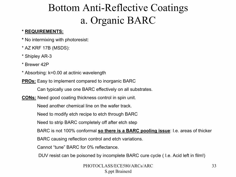
Bottom Anti-Reflective Coatingsa. Organic BARC
* REQUIREMENTS:
* No intermixing with photoresist:
* AZ KRF 17B (MSDS):
* Shipley AR-3
* Brewer 42P
* Absorbing: k=0.00 at actinic wavelength
PROs: Easy to implement compared to inorganic BARC
Can typically use one BARC effectively on all substrates.
CONs: Need good coating thickness control in spin unit.
Need another chemical line on the wafer track.
Need to modify etch recipe to etch through BARC
Need to strip BARC completely off after etch step
BARC is not 100% conformal so there is a BARC pooling issue: I.e. areas of thicker
BARC causing reflection control and etch variations.
Cannot “tune” BARC for 0% reflectance.
DUV resist can be poisoned by incomplete BARC cure cycle ( I.e. Acid left in film!)

PHOTOCLASS/ECE580/ARCs/ARCS.ppt Brainerd
34
Bottom Anti-Reflective Coatingsa. Organic BARC Typical components
* POLYMERS: DYES
*
Dye dimers
NH
O
CN
HO
O
NH
ONCO
HO
H3C
H3C
anthracene derivatives (DUV)
X=CH2OH, COOH, NH2, ...X
Coumarin 138 (λmax = 365 nm)
O ON
Curcumin (λmax = 430 nm)
HO
H3CO O
OH
OH
OCH3
Sudan Orange G (λmax = 388 nm)
NN OH
HO
Coumarin 7 (λmax = 437 nm)
O O
N
N
N
H
O
OO
O
N
N
O
O
O
NH
NH
OHOOC
COOH
-2 H2O
polyimide(cured form)
polyamic acid (apply form)
can be made to be developer soluble by partial curing
SO2 O
SO2 CH2 CH
CH2
CH3
PBS
PHOTOCLASS/ECE580/ARCs/ARCS.ppt Brainerd
35
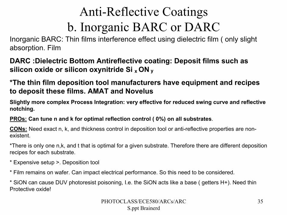
Anti-Reflective Coatingsb. Inorganic BARC or DARC
Inorganic BARC: Thin films interference effect using dielectric film ( only slight absorption. Film
DARC :Dielectric Bottom Antireflective coating: Deposit films such as silicon oxide or silicon oxynitride Si x ON y
*The thin film deposition tool manufacturers have equipment and recipes to deposit these films. AMAT and NovelusSlightly more complex Process Integration: very effective for reduced swing curve and reflective notching.
PROs: Can tune n and k for optimal reflection control ( 0%) on all substrates.
CONs: Need exact n, k, and thickness control in deposition tool or anti-reflective properties are non-existent.
*There is only one n,k, and t that is optimal for a given substrate. Therefore there are different deposition recipes for each substrate.
* Expensive setup >. Deposition tool
* Film remains on wafer. Can impact electrical performance. So this need to be considered.
* SiON can cause DUV photoresist poisoning, I.e. the SiON acts like a base ( getters H+). Need thin Protective oxide!

PHOTOCLASS/ECE580/ARCs/ARCS.ppt Brainerd
36
Anti-Reflective Coatings: Complete treatment with absorbing film
Clariant Antireflective Coatings Lecture Notes
t e-ik2x
medium 2
e-ik1x
r e-ik1x
medium 1
( ))kk(inn
iknññ
ñtt2121
22
21
212
22+++
−=
+==
)kk(inn)kk(inn
ññññrr
2121
2121
21
2112 +++
−+−=
+−
==
for normal incidencer12, t12: Fresnel coefficients for reflection and transmission
( ) ( )( ) ( )2
212
21
221
221
2121
2121
2121
2121
1212
kknnkknn
)kk(inn)kk(inn
)kk(inn)kk(inn
rr*rrR = % reflectivity *
+++−+−
=
+−+−−−
⋅+++−+−
=
⋅=⋅=

PHOTOCLASS/ECE580/ARCs/ARCS.ppt Brainerd
37
Anti-Reflective Coatings: Absorbing Film Reflection at interface of two medium: PR = ñ = 1.60 - 0.02i
Clariant Antireflective Coatings Lecture Notes
( )( )
( ) ( )( ) ( )R
n k
n kR
n n k k
n n k kair
Si Si
Si SiPR
PR Si PR Si
PR Si PR Si
=− +
+ +=
− + −
+ + +
1
1
2 2
2 2
2 2
2 2;
0
1
2
3
4
5
6
7
200 250 300 350 400 450 500
wavelength [nm]
n ASP
k ASP
Si
0
0.1
0.2
0.3
0.4
0.5
0.6
0.7
0.8
200 300 400 500 600
wavelength [nm]
refle
ctan
ceR into airR into resist
Si
PHOTOCLASS/ECE580/ARCs/ARCS.ppt Brainerd
38
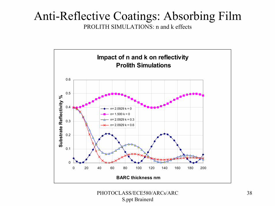
Anti-Reflective Coatings: Absorbing Film PROLITH SIMULATIONS: n and k effects
Impact of n and k on reflectivity Prolith Simulations
0
0.1
0.2
0.3
0.4
0.5
0.6
0 20 40 60 80 100 120 140 160 180 200
BARC thickness nm
Subs
trat
e R
efle
ctiv
ity %
n= 2.0929 k = 0
n= 1.500 k = 0
n= 2.0929 k = 0.3
n= 2.0929 k = 0.6

PHOTOCLASS/ECE580/ARCs/ARCS.ppt Brainerd
39
Inorganic BARC: DARCDielectric Anti-Reflective Coating
• SiOxNy Thickness PROLITH SIMULATIONS

PHOTOCLASS/ECE580/ARCs/ARCS.ppt Brainerd
40
Inorganic BARC: DARCDielectric Anti-Reflective Coating
• SiOxNy

PHOTOCLASS/ECE580/ARCs/ARCS.ppt Brainerd
41
Inorganic BARC: DARCDielectric Anti-Reflective Coating
• SiOxNy Thickness for various Polysilicon Thicknesses

PHOTOCLASS/ECE580/ARCs/ARCS.ppt Brainerd
42
Inorganic BARC: DARCDielectric Anti-Reflective Coating
• SiOxNy Thickness for various Top oxideThicknesses

PHOTOCLASS/ECE580/ARCs/ARCS.ppt Brainerd
43
Inorganic BARC: DARCDielectric Anti-Reflective Coating
http://www.semiconductor.net/semiconductor/issues/issues/2000/200010/six001007met.asp