alerts support
TRANSCRIPT

AS/400 Advanced Series IBM
Alerts SupportVersion 4
SC41-5413-00


AS/400 Advanced Series IBM
Alerts SupportVersion 4
SC41-5413-00

Note
Before using this information and the product it supports, be sure to read the general information under “Notices” on page v.
First Edition (August 1997)
This edition applies to the licensed program IBM Operating System400 (Program 5769-SS1), Version 4 Release 1 Modification 0,and to all subsequent releases and modifications until otherwise indicated in new editions.
Make sure that you are using the proper edition for the level of the product.
Order publications through your IBM representative or the IBM branch serving your locality. If you live in the United States, PuertoRico, or Guam, you can order publications through the IBM Software Manufacturing Solutions at 1-800-879-2755. Publications arenot stocked at the address given below.
IBM welcomes your comments. A form for readers' comments may be provided at the back of this publication. You can also mailyour comments to the following address:
IBM CorporationAttention Department 542IDCLERK3605 Highway 52 NRochester, MN 55901-7829 USA
or you can fax your comments to:
United States and Canada: 1-800-937-3430Other countries: 1-507-253-5192
If you have access to the Internet, you can send your comments electronically to [email protected]; IBMMAIL,to IBMMAIL(USIB56RZ).
When you send information to IBM, you grant IBM a nonexclusive right to use or distribute the information in any way it believesappropriate without incurring any obligation to you.
Copyright International Business Machines Corporation 1997. All rights reserved.Note to U.S. Government Users — Documentation related to restricted rights — Use, duplication or disclosure is subject torestrictions set forth in GSA ADP Schedule Contract with IBM Corp.

Contents
Notices . . . . . . . . . . . . . . . . . . . . . . vTrademarks . . . . . . . . . . . . . . . . . . . . v
About Alerts Support, SC41-5413 . . . . . . vii
Who Should Read This Book . . . . . . . . . . viiPrerequisite and Related Information . . . . . viiInformation Available on the World Wide Web vii
Part 1: Learning about Alerts
Chapter 1. How to Use Alerts to SimplifyYour Network Management . . . . . . . . 1-1
What Are Alerts? . . . . . . . . . . . . . . . . 1-1Why Would I Want to Use Alerts? . . . . . . 1-1What Is Required to Set Up Alerts? . . . . . 1-1What Options Do I Have to Configure Alerts? 1-2Where Do I Send My Alerts? . . . . . . . . . 1-2
Primary Focal Point . . . . . . . . . . . . . 1-2Default Focal Point . . . . . . . . . . . . . 1-2Backup Focal Point . . . . . . . . . . . . . 1-3Requested Focal Point . . . . . . . . . . . 1-3
What Is Sphere of Control? . . . . . . . . . . 1-3Removing Systems from the Sphere of
Control . . . . . . . . . . . . . . . . . . . 1-3What Is the Best Way To Organize My
Alerts? . . . . . . . . . . . . . . . . . . . . . 1-3Using Nested Focal Points on a
System/370 . . . . . . . . . . . . . . . . . 1-4What Do I Need to Consider When I
Configure My AS/400 . . . . . . . . . . . . . 1-4Other Ways to Configure Your AS/400
System . . . . . . . . . . . . . . . . . . . 1-4What Ways Are There to Create Alerts? . . 1-5
An Example of a Message Queue . . . . 1-5Questions That Decide If a Message
Should Be Alertable . . . . . . . . . . . . 1-5
Where Can I Send My Alerts? . . . . . . . . 1-6Can I Save My Alerts? . . . . . . . . . . . . . 1-6Can I Delete My Alerts? . . . . . . . . . . . . 1-6Can I Define My Own Alertable Messages? 1-6Can I Use Alerts With NetView? . . . . . . . 1-7Can I Display My Alerts? . . . . . . . . . . . 1-7
Can I Select Which Alerts to Display? . . 1-7Are There Any Design Tips for Alerts? . . . 1-8What Are Some Ways to Use Alerts? . . . . 1-9
Setting up a SimpleEnvironment—Scenario . . . . . . . . . . 1-9
Setting Up Alert Filters for aNetwork—Scenario . . . . . . . . . . . . 1-9
Simple Monitoring—Scenario . . . . . . 1-10What Do I Need to Consider When I
Configure My System/36 or System/38 forAlerts? . . . . . . . . . . . . . . . . . . . . 1-13
Other Alert Support Issues for aSystem/36 or a System/38 . . . . . . . 1-13
Are There Other Ways to Analyze MyAlerts? . . . . . . . . . . . . . . . . . . . . 1-14
Work with Problems Command . . . . . 1-14Work with Alerts Command . . . . . . . 1-14Analyze Problem Command . . . . . . . 1-14
Where Can I Find More Information? . . . 1-14
Part 2: Using Alerts
Chapter 2. Setting Up OS/400 AlertSupport . . . . . . . . . . . . . . . . . . . . 2-1
Configuring Your Network for Alerts . . . . . 2-1Sessions Used for Alert Support . . . . . 2-1An Example Network . . . . . . . . . . . . 2-2
AS/400 Configuration . . . . . . . . . . . . . 2-3Network Attributes for Alerts . . . . . . . . 2-4
The Sphere of Control . . . . . . . . . . . . . 2-7Working with the Sphere of Control . . . . 2-8Displaying the Sphere of Control Status 2-10
Additional Considerations . . . . . . . . . . 2-11Nested Focal Points . . . . . . . . . . . 2-11Looping Considerations . . . . . . . . . 2-11
Held Alerts . . . . . . . . . . . . . . . . . 2-11Switched Line Considerations . . . . . . 2-12Management Services Session . . . . . 2-12Alert Controller Session . . . . . . . . . 2-13Alert Support through an SNA Subarea
Network . . . . . . . . . . . . . . . . . . 2-14Interconnected Network Considerations 2-14Performance Considerations . . . . . . . 2-14
Chapter 3. Using OS/400 Alert Support . 3-1OS/400 Alerts . . . . . . . . . . . . . . . . . . 3-1
Working with OS/400 MessageDescriptions . . . . . . . . . . . . . . . . 3-1
Copyright IBM Corp. 1997 iii

Alerts and Local Problem Analysis . . . . 3-4Alert Messages for General Use . . . . . 3-5Operator-Generated Alerts . . . . . . . . . 3-6Application-Generated Alerts . . . . . . . 3-7
Creating an Alert Table . . . . . . . . . . . . 3-7Additional Alert Table Commands . . . . . 3-8
Adding Alert Descriptions to an Alert Table . 3-8Detailed Data for Causes and Actions . 3-10Product Identifiers for Causes and
Actions . . . . . . . . . . . . . . . . . . 3-10Additional Alert Description Commands 3-11Working with Alert Descriptions . . . . . 3-11
Working with Alerts . . . . . . . . . . . . . . 3-13The Alert Database . . . . . . . . . . . . 3-13Working with Logged Alerts . . . . . . . 3-14SNA Generic Alerts . . . . . . . . . . . . 3-24
Chapter 4. OS/400 Alert Filter Support . 4-1
Filter Components . . . . . . . . . . . . . . . 4-1Selection Entries . . . . . . . . . . . . . . 4-1Action Entries . . . . . . . . . . . . . . . . 4-1
Working with Alert Filters . . . . . . . . . . . 4-2Working with Alert Selection Entries . . . 4-3Working with Alert Action Entries . . . . . 4-4Printing Alert Filters and Filter Components 4-5
Setting Up Alert Filters for a Network . . . . 4-5Creating the Alert Filter for the ATLANTA
System . . . . . . . . . . . . . . . . . . . 4-5Creating the Alert Filter for the SEATTLE
System . . . . . . . . . . . . . . . . . . . 4-7Creating the Alert Filter for the CHICAGO
System . . . . . . . . . . . . . . . . . . . 4-7Creating the Alert Filter for the STLOUIS
System . . . . . . . . . . . . . . . . . . . 4-7 Using a Systems Management Application
with Alert Filters . . . . . . . . . . . . . . . . 4-7
Appendixes
Appendix A. Sample Procedures forOS/400 Alerts . . . . . . . . . . . . . . . . . A-1
Examples of Creating an Alert Table . . . . A-1An Example of Adding an Alert Description . A-1Example of Alertable Message with
Substitution Variables . . . . . . . . . . . . A-2
Appendix B. IBM-Supplied AlertableMessages . . . . . . . . . . . . . . . . . . . B-1
QCPFMSG Messages withALROPT(*IMMED) . . . . . . . . . . . . . . B-1
QCPFMSG Messages withALROPT(*DEFER) . . . . . . . . . . . . . . B-8
QCPFMSG Messages withALROPT(*UNATTEND) . . . . . . . . . . B-25
Appendix C. Alerts Differences . . . . . . C-1Differences from System/36 Alert Support . C-1Differences from System/38 Alert Support . C-2
Appendix D. Migration Concerns . . . . . D-1Looping Considerations . . . . . . . . . . . . D-1Held Alerts . . . . . . . . . . . . . . . . . . . . D-1
Bibliography . . . . . . . . . . . . . . . . . . X-1IBM Publications . . . . . . . . . . . . . . . . X-1
Communications and Programming . . . . X-1NetView . . . . . . . . . . . . . . . . . . . . X-1NetView Distribution Manager . . . . . . . X-2Advanced Communications Function for
Virtual Telecommunications AccessMethod (ACF/VTAM) . . . . . . . . . . . X-2
Systems Network Architecture (SNA) . . . X-2Data Link Control . . . . . . . . . . . . . . X-2Communications Controllers . . . . . . . . X-2Personal Computer . . . . . . . . . . . . . X-2System/36 . . . . . . . . . . . . . . . . . . X-2System/38 . . . . . . . . . . . . . . . . . . X-2
Index . . . . . . . . . . . . . . . . . . . . . . . X-3
iv OS/400 Alerts Support V4R1

Notices
References in this publication to IBM products,programs, or services do not imply that IBMintends to make these available in all countries inwhich IBM operates. Any reference to an IBMproduct, program, or service is not intended tostate or imply that only that IBM product, program,or service may be used. Subject to IBM's validintellectual property or other legally protectablerights, any functionally equivalent product,program, or service may be used instead of theIBM product, program, or service. The evaluationand verification of operation in conjunction withother products, except those expressly designatedby IBM, are the responsibility of the user.
IBM may have patents or pending patent applica-tions covering subject matter in this document.The furnishing of this document does not give youany license to these patents. You can sendlicense inquiries, in writing, to:
IBM Director of LicensingIBM Corporation500 Columbus AvenueThornwood, NY 10594U.S.A
Licensees of this program who wish to have infor-mation about it for the purpose of enabling: (i) theexchange of information between independentlycreated programs and other programs (includingthis one) and (ii) the mutual use of the informationwhich has been exchanged, should contact thesoftware interoperability coordinator. Such infor-mation may be available, subject to appropriateterms and conditions, including in some cases,payment of a fee. Address your questions to:
IBM CorporationSoftware Interoperability Coordinator3605 Highway 52 NRochester, MN 55901-7829U.S.A.
This publication could contain technical inaccura-cies or typographical errors.
This publication may refer to products that are notcurrently available. IBM makes no commitment tomake available any unannounced products
referred to herein. The final decision to announceany product is based on IBM's business and tech-nical judgment.
This publication contains examples of data andreports used in daily business operations. To illus-trate them as completely as possible, the exam-ples include the names of individuals, companies,brands, and products. All of these names are ficti-tious and any similarity to the names andaddresses used by an actual business enterpriseis entirely coincidental.
This publication contains small programs that arefurnished by IBM as simple examples to providean illustration. These examples have not beenthoroughly tested under all conditions. IBM, there-fore, cannot guarantee or imply reliability, service-ability, or function of these programs. All programscontained herein are provided to you “as is.” Theimplied warranties of merchantability andfitness for a particular purpose are expresslydisclaimed.
Trademarks
The following terms are trademarks of the IBMCorporation in the United States or other countriesor both:
ACF/VTAMAnyNetApplication System/400AS/400IBMNetViewOperating System/400Operational AssistantOS/2OS/400SystemViewSystem/370System/390VTAM400
Other company, product, and service names,which may be denoted by a double asterisk (**),may be trademarks or service marks of others.
Copyright IBM Corp. 1997 v

vi OS/400 Alerts Support V4R1

About Alerts Support, SC41-5413
This book is intended for the programmer whoneeds to understand how to manage a system byusing alerts support or for the programmer whowants to understand how to manage a network.
Who Should Read This Book
Using this book, the AS/400 programmer can:
� Configure the AS/400 system to use alertsupport.
� Allow end-user applications to create alertsand notify the OS/400alert manager of previ-ously created alerts that need to be handled.
� Control the creating, sending, and logging ofalert messages for problem management.
� Perform central site problem analysis for theAS/400 systems in a network.
You should be familiar with the following to usethe information in this book:
� AS/400 programming terminology. You shouldalso be familiar with the terminology of thehost system
� Data communications concepts.
� Configuration and communications informationthat is provided in the books: CommunicationsConfiguration, SC41-5401, and Communi-cations Management, SC41-5406
This book is divided into three parts:
� Part 1: Learning about Alerts
� Part 2: Using Alerts
� Part 3: Additional Information
Part 1 presents material that gives the user theopportunity to learn about alerts on a how-to level.Part 2 and Part 3 contain detailed reference mate-rial that was formerly contained in the DSNXSupport, SC41-5409 book.
Prerequisite and RelatedInformation
For information about Advanced 36 publications,see the Advanced 36 Information Directory,SC21-8292, in the AS/400 Softcopy Library.
For information about other AS/400 publications(except Advanced 36), see either of the following:
� The Publications Reference, SC41-5003, inthe AS/400 Softcopy Library.
� The AS/400 Information Directory, a unique,multimedia interface to a searchable databasethat contains descriptions of titles availablefrom IBM or from selected other publishers.
For a list of related publications, see the“Bibliography” on page X-1.
Information Available on theWorld Wide Web
More AS/400 information is available on the WorldWide Web. You can access this information fromthe AS/400 home page, which is at the followinguniversal resource locator (url) address:
http://www.as4ðð.ibm.com
Select the Information Desk, and you will be ableto access a variety of AS/400 information topicsfrom that page.
Copyright IBM Corp. 1997 vii

viii OS/400 Alerts Support V4R1

Part 1: Learning about Alerts
Copyright IBM Corp. 1997

OS/400 Alerts Support V4R1

Chapter 1. How to Use Alerts to Simplify Your NetworkManagement
This chapter provides an overview of alerts andhow alerts can better serve your systems manage-ment needs. If alerts are new to you, this chaptergives you the opportunity to learn about them at ahow-to level. If you are experienced in workingwith alerts, this chapter gives you the opportunityto learn about parts of alert management that younever knew existed.
What Are Alerts?
Alerts are specific types of system messages thatare used to identify problems or impending prob-lems. When you set up your system for alertsupport, you receive an alert system messagewhenever a problem has occurred or whenever aproblem is about to occur. These alert messageshelp you to manage your systems and networkmore efficiently.
OS/400 alerts support provides you analysis dataabout the cause of a problem or impendingproblem. By summarizing the problem and givingthe network or system operator guidance on cor-rective actions to the problem, alert supportassists you in better managing both your networkand the systems within your network.
Also, alerts support has both the flexibility to runon different machines and the rigidity to providenotification and analysis on specific problems.
Why Would I Want to Use Alerts?
You would want to use alert support because alertsupport helps you manage your network andsystems more effectively. The following situationsare examples of reasons to use alerts:
� If you need to have all your technical peopleat one location.
By using alerts support, you can staff all ofyour technical support at one central site.
� If you run your own application on yoursystem.
Alert support gives you the capability to defineyour own alertable messages so that yourown applications has the same error reportingcapabilities as the system functions.
� If you need the flexibility to choose where yourtechnical support is located.
With alert support, you can select which ofyour systems will receive technical supportfrom your technical centers.
� If you manage a network with either homoge-neous or heterogenous systems.
Because alerts are designed to be inde-pendent of the system architecture, alerts fromone system are readable on other systems.
� If you must monitor your network status.
Alerts support information about specificnetwork problems can help you track andmonitor your system.
� If you must reduce your system and networkcosts.
Because the system automatically controls thecapabilities of alerts, you can automatecommon responses to system problemswithout operator intervention.
� If you have unattended remote systems.
Alerts can notify a central site about aproblem on a unattended system.
What Is Required to Set UpAlerts?
Alerts are set up in user applications by usingmessage files for their messages and alert tablesfor their alert descriptions. If the message isalertable, the following is required:
� An alert message must be in the message file.
� An alert description must be in the alert table.
� The message file and the alert table musthave the same name.
Copyright IBM Corp. 1997 1-1

� The message file and the alert table must bein the library list of the job that generates thealerts.
Alerts implementation in this way removes someof the complexity in the ability to create uniquealerts.
What Options Do I Have toConfigure Alerts?
You can configure your alerts by setting up eithera sphere of control or an alert controller session.
If you configure your AS/400 business computingsystem by using sphere of control, the system thatserves as the focal point establishes a controlpoint session with every system that is definedunder the focal point sphere of control. An AS/400focal point is an AS/400 system that is defined toreceive alerts. A focal point sphere of control is acollection of nodes within your APPN network thatsends alerts to the focal point. If you decide to usesphere of control, you must have advancedprogram-to-program communications (APPC) andAdvanced Peer-to-Peer Networking (APPN)support on your AS/400 system.
If you configure your AS/400 system by using analert controller session, you define the system towhich alerts are sent as an alert controller. Youcan use an alert controller to configure yourAS/400 system without the need for APPCsupport. This configuration does not support thesphere of control function and does not requireyou to define any focal points.
Where Do I Send My Alerts?
Actually, you do not send your alerts anywhere.Instead, the system determines where to send thealerts based on the focal point of that system.When you use APPC and APPN support, the focalpoint system establishes a management servicessession with other systems that are defined underthe focal point's sphere of control. Alerts are sentthrough this management services session to afocal point.
Because the sphere of control function is such apowerful function, it is best that you use a man-
agement services session to configure your alertsand not alert controller sessions.
You should select the system that you want to useas the focal point for your network based on whichsystem is the most centralized in your network.You can find out where the system is sendingyour alerts by using the Work with Alerts(WLKALR) command.
The AS/400 system also provides the capability tonest focal points. Nested focal points allows you todefine a hierarchy of focal points where the high-level focal points accept alerts collected by low-level focal points.
The four types of focal points are:
� Primary focal point
� Default focal point
� Backup focal point
� Requested focal point
Primary Focal Point
A primary focal point is an AS/400 APPN nodethat defines all nodes under its sphere of control.Your primary focal point has two functions:
� Establish a management services session toyour nodes.
� Reestablish the management services sessionwhenever the link is lost or reconnected.
You can define your node as the primary focalpoint by using the Change Network Attribute(CHGNETA) command:CHGNETA ALRSTS(\ON) ALRPRIFP(\YES) ALRDFTFP(\NO) ALRLOGSTS(\ALL)
ALRCTLD(\NONE)
The alert primary focal point (ALRPRIFP) param-eter defines whether the node is a primary alertfocal point.
Default Focal Point
A default focal point is an AS/400 network nodethat acts as a focal point for all network nodes thatare not under the sphere of control of an activeprimary focal point. A default focal contains onlynetwork nodes. The purpose of a default focalpoint is to ensure that all network nodes have aplace to send their alerts.
1-2 OS/400 Alerts Support V4R1

You should define your focal point system as aprimary focal point and not as a default focalpoint. However, if you need to define your systemas a default focal point, you should have only asingle default focal point.
You can define your node as the default focalpoint by using the following command:CHGNETA ALRSTS(\ON) ALRPRIFP(\NO) ALRDFTFP(\YES) ALRLOGSTS(\ALL)
ALRCTLD(\NONE)
The alert default focal point (ALRDFTFP) param-eter defines whether your node is a default alertfocal point.
Backup Focal Point
A backup focal point is an AS/400 system that isused as a focal point only when other nodescannot communicate with their primary focal point.Your primary focal point identifies the system thatwill serve as the backup focal point.
You can define your node as the backup focalpoint by using the following command:
CHGNETA ALRBCKFP(netid id)
You must have the ALRPRIFP parameter set to*YES for the backup focal point system.
Requested Focal Point
A requested focal point is an AS/400 systemthat has been designated by a node as the focalpoint system to which data is sent. A node canrequest its focal point. You need to use arequested focal point when the entry point is theonly node that knows when a link needs to be re-established.
You can define your node as the requested focalpoint by using the following command:
CHGNETA ALRRQSFP(network cp)
The following are requirements for setting up anAS/400 system as a requested focal point:
� You must use the alert requested focal point(ALRRQSFP) parameter to specify the focalpoint system to which alerts are to be sent.
� You must have the ALRPRIFP parameter setto *YES for the requested focal point system.
What Is Sphere of Control?
You can manage which systems are under whosecontrol by setting up a sphere of control. Thesphere of control specifies the systems within anetwork that send alerts to their primary focalpoint. The sphere of control allows you to bettermanage the complexity of a large and ever-growing network.
You can use the Work with Sphere of Control(WRKSOC) command to add systems to a sphereof control. Also, systems within the sphere ofcontrol can be automatically assigned to a default,requested, or backup focal point by the AS/400system.
Removing Systems from theSphere of Control
You can use the Remove Sphere of Control Entry(RMVSOCE) command to remove systems from afocal point's sphere of control. You should want toremove a system from a focal point sphere ofcontrol for the following reasons:
� A system is physically removed from anetwork.
� A system is replaced by another system thathas a different name.
� A system no longer needs technical support.
A focal point in the sphere of control should not beremoved from the sphere of control until anotherfocal point has started focal point services to thatsystem. This ensures that a system always has afocal point.
What Is the Best Way ToOrganize My Alerts?
The best way to organize your alerts is to build ahierarchical structure of focal points. A hierarchicalstructure of focal points is referred to as nestedfocal points. A nested focal point is a focal pointthat is defined within the sphere of control ofanother focal point. By nesting focal points, alertsthat are collected by lower-level focal points areforwarded to their higher-level focal point.
Chapter 1. How to Use Alerts to Simplify Your Network Management 1-3

The advantages of nesting focal points are that afocal point can be configured so that alerts arerouted through fewer APPN nodes and that therecan be fewer management services sessions onany given system. The disadvantage of nestingfocal points is that the management for the sphereof control is performed on more than one system.
Make sure that the ability of your central site tohandle alerts does not exceed the ability of youroperator to handle those alerts. For example, if asingle sphere of control manages 200 systemsand each system generates five alerts each day,your operators will need to handle 1000 alertsevery day.
Because system alerts are automatically sent totheir APPN end node, APPN nodes do not have tobe added to the sphere of control. This decreasesthe time spent on network configuration andreduces the number communication sessionsneeded.
Using Nested Focal Points on aSystem/370
In a System/370 host environment, NetView isusually the highest focal point that receives alertsfrom downstream AS/400 focal points. When usingthis approach, you need to consider the following:
� You may have AS/400 systems in the networkthat are not directly connected to System/370.Alerts gathered from these systems are for-warded on to NetView by using AS/400 focalpoint support.
� Other AS/400 systems may have the appro-priate skills to manage the network in theirown region. In this case, alerts are forwardedto NetView for statistical purposes, but thenetwork management functions remain ontheir local AS/400 systems.
� You may have AS/400 systems that are dedi-cated only for one particular type of applica-tion. These systems could be the focal pointsthat only track and resolve alerts for thoseparticular application type.
� You may have network cost savings when youuse nested focal points. This is especially trueif the central site system is in a differentgeographic location. Typically, the more locala system is, the less expensive the networkcost will be.
What Do I Need to ConsiderWhen I Configure My AS/400
You can configure your AS/400 system for alertseither with the configuration menus or with thecontrol language commands. OS/400 networkattributes are used to define your AS/400 systemto be a focal point and to control other alert func-tion. You can use the Change Network Attributes(CHGNETA) command to change the networkattributes. The following alert functions are con-trolled by OS/400network attributes:
� Alert status
� Alert logging status
� Alert primary focal point
� Alert default focal point
� Alert backup focal point
� Alert focal point to request
� Alert controller description
� Alert hold count
� Alert filter
Other Ways to Configure YourAS/400 System
You can use the Display Network Attributes(DSPNETA) command to display the currentvalues of your network attributes.
Although you can configure your AS/400 systemto provide focal point services, you can also con-figure your AS/400 system in the following ways:
� A system that is not a focal point but sendsand forwards alerts to another system that is afocal point. For example, an AS/400 systemthat is not a focal point can still generatealerts and receive alerts from a 5494 con-troller. If this AS/400 system does not have anon-site operator handling these alerts, thenthe alerts can be forwarded to anothersystem.
� A focal point in the network that is notattached to the host system. For example, anAS/400 system can be the host system andnot need to forward any of its alerts to othersystems.
1-4 OS/400 Alerts Support V4R1

� A nested focal point that forwards alerts to theNetView program from an APPN network. Forexample, you can reduce the number of man-agement services sessions to your hostsystem by designating an AS/400 system as afocal point. Any alert automatic handling canbe done on the focal point. All other alerts canbe handled by operators who use the NetViewprogram to forward the alerts to aSystem/390.
What Ways Are There to CreateAlerts?
When a problem or an impending problem occurson an AS/400 system, alerts are created in the fol-lowing ways:
� You can use the alert status control attributeto create alerts for the entire system.
� You can use the Change Message Queue(CHGMSGQ) command to determine whetherthe message queue is defined to acceptalerts. If the message queue is defined toallow alerts, then alerts are created.
Note: QSYSOPR message queue defaults toaccept alerts. Also, QHST messagequeue is required to accept alerts.
� You can use the alert option on the messagedescription to create alerts. This allows you tocontrol exactly which messages can create analert.
An Example of a Message Queue
The following is an example of how messagequeues are used to generate an alert.
� Given that the following is true:
– Message ABC1234 has an alert option of*IMBED.
– Message XYZ6789 has an alert option of*NO.
– Message queue NOALERT does not allowalerts to be created.
– Message queue ALERT allows alerts tobe created.
� Then, the following is also true:
– Alerts are not created on any messagequeue when the alert status is *OFF.
– Alerts are not created on the NOALERTqueue when the alert status is *ON.However, alerts are created for MessageABC1234 on the ALERT message queue.
Questions That Decide If aMessage Should Be Alertable
When you are deciding whether a messageshould be alertable, you need to ask the followingquestions.
� Do you want your system to send any alerts?
Set the alert status network attribute to *ONwhen you want to create alerts.
� Does your system have a local operator?
Set the alert status network attribute to*UNATTEND when there is not a local oper-ator. Set the alert status network attribute to*ON when there is a local operator.
� Is local problem analysis available for theproblem?
Set the alert option to *DEFER to run localproblem analysis when it is available.
� Does problem analysis provide a local resol-ution to the problem?
Create an alert to report that a problemoccurred and was analyzed, but a local resol-ution was not found.
� Should the system message be forwarded toanother location for handling?
To forward the system message to anotherlocation for handling, set the alert status to*UNATTEND. When a system operator ispresent, set the alert status to *ON.
� Do you want to send an alert that reports theoutcome of problem analysis?
To send an alert that reports the outcome ofproblem analysis, set the alert status to *ONand set the alert option to *DEFER.
Chapter 1. How to Use Alerts to Simplify Your Network Management 1-5

Where Can I Send My Alerts?
Alerts that are created on an AS/400 system canbe sent to any other system in the network if thesystem is a focal point system. Also, alerts can besent to a System/370 system if it has NetViewsupport.
The sending and forwarding of alerts are basicallythe same. They both use the same sphere ofcontrol commands, they both are received by thefocal point system in the same way, and they areboth part of the OS/400 program.
The difference between sending an alert and for-warding an alert can be summarized as follows:
� The entry point system sends the alert toanother system (the system that creates analert).
� The focal point system forwards the alerts toanother focal point system (the system thatreceives an alert).
The biggest benefit that forwarding alerts has oversending alerts is that the alert message can besent to where the problem can best be handled.
You can use either the management servicessession or the alert controller session to forwardalerts. If an AS/400 system is forwarding the alertto another AS/400, then a management servicessession should be used. If an AS/400 system isforwarding the alert to a system other than anAS/400system, then an alert controller sessionmust be used. Because the management servicessession supports the sphere of control function,use the management services sessions wheneverthey are available.
Can I Save My Alerts?
You can save your alerts by logging them into thealert database. The main benefit to logging alertsinto the alert database is to control the number ofalerts that the operator is required to handle fromone moment to the next. You can do this if youhave created an alert on your local AS/400 systemor have received alerts from another AS/400system. You can control which alerts are loggedinto the database either by using the ChangeNetwork Attribute (CHGNETA) command or by
using an alert filter. An alert filter assigns eachalert to a group and specifies the actions to takeplace for each group.
Alerts are also saved in the alert database whenthey cannot be sent to their designated focal pointsystems. These alerts are referred to as heldalerts . Alerts become held alerts when either anetwork problem exists or if the number of alertsheld is less than the value of the alert hold count(ALRHLDCNT) network attribute. ALRHLDCNTcan assigned only when you use the alert con-troller description (ALRCTLD) network attribute.
When logged into the alert database, all heldalerts are marked for sending at a later time.When you or the system resolves the networkproblem or when the number of held alerts equalsthe value specified in ALRHLDCNT parameter, thealerts are sent to their designated focal point.
You can display logged or held alerts by using theWork with Alerts (WRKALR) command.
Can I Delete My Alerts?
To delete unwanted alerts from the alert databaseyou can use either the Work with Alerts(WRKALR) command or the Delete Alert(DLTALR) command. You delete alerts from thealert database when you want to control the sizeof the alert database and to free up needed diskstorage. Use the QAALERT command to deter-mine the size of your alert database.
Also, you can use Operational Assistant cleanupto automatically control the size of the alert data-base during system log cleanup.
Can I Define My Own AlertableMessages?
You can define any system messages as alertablejust by changing the alert option (ALROPT)parameter in the message description. This allowsyour AS/400 system to make any messagealertable whether it is a system or user message.For a list of current alertable messages, seeAppendix B, IBM-Supplied Alertable Messages.
Being able to define your own alertable messagesgives you greater flexibility in managing your
1-6 OS/400 Alerts Support V4R1

network and those systems within that network. Bydefining your own alertable messages, specificnetwork and system conditions can be monitored.
Can I Use Alerts With NetView?
The NetView licensed program allows aSystem/370 host or a System/390 host to commu-nicate with an AS/400 system. The NetViewprogram provides the focal point capabilities sothat the host system operator can display thealerts and perform the appropriate problem anal-ysis based on the alert. All activities can be donefrom a System/370 or System/390 without theneed of a AS/400 system.
To send your alerts over to NetView, you shoulduse the NetView sphere of control commands.NetView sphere of control commands are similarto the sphere of control commands found on anAS/400 system. Another way to send alerts overto a System/370 or a System/390 is through thealert controller description. Because of its flexi-bility, use the NetView sphere of control com-mands instead of the alert controller description.
The NetView commands also provide the focalpoint capabilities so that the host system operatorcan display the alert and perform the appropriateproblem analysis based on the alert.
Can I Display My Alerts?
You can display an alert by using the Work withAlerts (WRKALR) command. Besides displayingpossible causes of the alert, the WRKALRcommand also displays any recommended actionsthat are associated with the alert. You can use avariety of WRKALR parameters to control whichalert information is displayed and when it is dis-played. This control is especially useful when youcontrol alerts by an assigned user or an assignedgroup. (Assigning users and assigning groups aretwo ways to categorize alerts.)
When you display your alerts, the following infor-mation is displayed:
Resource hierarchy The lowest entry shows theresource name and the failing resourcetype. The resource hierarchy deter-mines which hardware resource failed
when it is a hardware resourceproblem.
Date/Time The date and time that the problemoccurred.
Note: The System/36 and System/38do not send the problem dateand time information to theAS/400 system.
Alert type and description entry The alert type(permanent, temporary, performance,impending problem, or unknown) com-bined with the description entry assistthe network operator in deciding thenext appropriate step in problem anal-ysis.
Probable causes The possible causes of theproblem in descending order.
Alert detail Additional displays show the messageID, message text, hardware details,and software details to provide moreinformation about the problem.
The following is an example of a Display AlertDetail display:
à ðDisplay Alert Detail
System: ROCHESTR
----------Resource Hierarchy------
Resource Name Resource Type
ROCHESTR CP
ATLANTA CP
CCð3 LC
RCHLIN LNK
Logged date/time . . . . . . : ð2/15/88 15:18:ð4
Problem date/time . . . . . : ð2/15/88 15:18:ð1
Assigned user . . . . . . . :
Group assigned . . . . . . . :
Filter . . . . . . . . . . . :
Library . . . . . . . . . :
Alert type . . . . . . . . . : Permanent
Alert description . . . . . : Unable to communicate with remote node
Probable causes . . . . . . : Communications
Communications/remote node
More...
Press Enter to continue.
F3=Exit F11=Display detail menu F12=Cancel F18=Display actions
á
ñ
Alert support also has a refresh capability thatautomatically refreshes the display screen.
Can I Select Which Alerts toDisplay?
You can select which alerts to display and at whatfocal point that you want to display the alerts byusing filters. You would want to use alert filteringfor the following reasons:
� The volume of alerts is reasonable for theoperators who are handling the alerts.
Chapter 1. How to Use Alerts to Simplify Your Network Management 1-7
� The alerts are being sent to operators basedon the expertise level of the operators.
Alert filtering is a function that assigns alerts intogroups and specifies what actions to take for eachgroup. Filtering is used at both the focal pointsystem and the entry point system.
At the focal point system, the system can handlean incoming alert either by assigning the alert to auser or by notifying a user automated program tothe alert.
At the entry point system, the system can use thealert filter to forward the alert either to a focalpoint system or to another entry point system. Allfiltering actions are valid at either the focal pointsystem or entry point system.
A filter consists of both selection entries andaction entries. A selection entry assigns eachalert that is processed by the filter to a group. Anaction entry specifies what should be done toprocess each group of alerts.
Selection Entries: The attributes that arecontained in the selection entries describe what tolook for in the alert. Each selection entry includesa logical expression that relates the alert attributeto a given value. Once an alert has satisfied aselection entry, the alert is assigned to a group.The group is a character value that the networkadministrator defines.
Use the Work with Filter Selection Entries(WRKFTRSLTE) command to access all the filterselection entry functions that are available. Youcan work with a list of filter selection entries toadd, change, copy, remove, display, move, or printthe selection entries.
Action Entries: Actions entries are definedby the network administrator as part of the filterobject. A filter object is an AS/400 object that canbe saved and restored. Part of the filteringprocess defines how the groups that are specifiedby the selection entries are mapped to the actionsthat will be taken.
Use the Work with Filter Action Entries(WRKFTRACNE) command to access all the filteraction entry functions that are available. You canwork with a list of filter action entries to add,
change, copy, remove, display, move, or print theaction entries.
Using the Data Queue for Automation: Youcan use data queues to help you automateresponses to alerts. When an alert is created orreceived by a system, the filter that is used by thealert is set up to send an alert notification recordto a data queue. Setting up a filter to send an alertnotification message is controlled by the SendData Queue (SNDDTAQ) parameter on the actionentry.
The data queue can be monitored by your ownsystem management application that is designedto automate responses to the alerts. When thealert notification is received by the data queue, theapplication can use the Retrieve Alert (QALRTVA)API to retrieve the alert from the alert database.Once the alert is retrieved, the application can dofurther processing that is required. Refer to theSystem API Reference book for more informationon the QALRTVA API.
Are There Any Design Tips forAlerts?
The following are design tips that help you get themost out of alert support.
� Do not send alerts and high priority data onthe same link because this causes alertthroughput to decrease.
� Try to evenly distribute the number of alertsthat are sent or received by a given system toprevent a delay in the logging of alerts.
� Because a large sphere of control requiressignificant processing time to re-establish asession, use nested focal points to reduce thesize of the sphere of control of a focal point.
� Try not to use default focal points. Becausethe default focal point tries to oversee theentire network, additional processing time isneeded whenever a node reenters thenetwork because the default focal point triesto get a session to the reentered node.
� If a default focal point is needed, eachnetwork should only have one. More than onedefault focal point in the network provides noadditional benefits and causes additional
1-8 OS/400 Alerts Support V4R1
system expense as default focal pointscompete for a new system.
� If you never want a message to be alertable,change the message descriptor so that thealert is not created rather than being filteredout. This saves processing time because thealert is never created and is therefore neverfiltered out. (Do this in a CL program the nexttime the operating system is installed so thatthe message descriptors are re-assigned theirdefault values.)
� Try to automate alerts as much as possible atthe entry point system so that the alerts donot have to flow to the central site.
What Are Some Ways to UseAlerts?
The following scenarios describe ways in which touse alerts.
Setting up a SimpleEnvironment—Scenario
Figure 1-1 on page 1-10 shows an example of asimple alert environment. The simple alert environ-ment has a primary focal point and two networknodes under the primary focal point's sphere ofcontrol.
NN1 is the primary focal point and has networknodes NN2 and NN3 under its sphere of control.NN1 is the primary focal point where all the skilledsupport people are located.
All end nodes (ENnn), by default, forward theiralerts to their network node servers (NNn). TheNNn forwards the alerts to NN1.
Because this is a simple alert environment, nobackup focal point is needed.
Note: A network node server does not have tobe defined as a focal point to receivealerts from an end node.
Expanded Example of Setting up aSimple Environment: Figure 1-2 onpage 1-11 contains an expanded example of asimple environment.
In this example, the office system is at the centralsite because the central site has the expertise ofCity1. The central site has the lowest workload ofall the systems. All other systems, except forsome of the production systems, are under theoffice system's sphere of control. Only one pro-duction system is under the office system sphereof control. That production system is the focalpoint for all other production systems. The prob-lems are handled by experts at the productionsite.
One of the shipping and distribution systems is thebackup focal point. It is also the backup focal pointfor the rest of the system.
An end node needs to be defined under a focalpoint sphere of control when the end nodenetwork node server belongs to a different sphereof control. For example, if the shipping system isan end node at City3, then the shipping systemneeds to be added to the office system sphere ofcontrol.
Setting Up Alert Filters for aNetwork—Scenario
Figure 1-3 on page 1-12 shows an examplenetwork with four AS/400 systems. The STLOUISsystem is the focal point, with SEATTLE,CHICAGO, and ATLANTA as entry point systemsin the STLOUIS system sphere of control. Thenetwork administrator decides that all alerts for allsystems should be sent to the focal point system.Because the operator who works on theCHICAGO system is an expert in resolving tapeproblems, however, all tape-related alerts for allsystems should be sent to CHICAGO.
The network administrator uses the ChangeNetwork Attributes (CHGNETA) command to des-ignate STLOUIS as the alert primary focal pointsystem. The network administrator at STLOUISuses the Work with Sphere of Control (WRKSOC)command to set up the sphere of control. Thesphere of control includes the nodes from whichSTLOUIS receives alerts. In this example, theentry point systems SEATTLE, CHICAGO, andATLANTA send their alerts to STLOUIS.
SEATTLE is an attended test system. All alertsare sent to the focal point STLOUIS. ATLANTA isan unattended system. As there is no operator
Chapter 1. How to Use Alerts to Simplify Your Network Management 1-9

City 1HQ
City 2
City 3
NN1
EN11 EN12 EN22EN21
EN31 EN32
NN2
NN3
RV3W300-1
Figure 1-1. Example of a Simple Alert Environment
who works on the ATLANTA system, all alerts aresent to STLOUIS. Tape alerts from both SEATTLEand ATLANTA are sent to CHICAGO.
The CHICAGO system is attended by an operatorwho specializes in tape problems. Therefore, alltape-related alerts from SEATTLE, ATLANTA, andSTLOUIS are received by CHICAGO. The oper-ator most qualified to handle the tape errors canwork on all tape problems for the network. AllCHICAGO alerts are sent to the focal pointSTLOUIS for processing.
The operators at STLOUIS work on all alerts fromall systems in the network, except for tape alerts.All tape alerts are sent to CHICAGO where theyare processed.
To set up the most efficient way to route andprocess the alerts, the network administratordecides to add filters to the network.
Simple Monitoring—Scenario
The following scenario provides an example onhow valuable alerts can be. Suppose that youwant to monitor a remote system withoutdepending on a remote system operator. The fol-lowing example sends a message from a remotesite to your central site every 15 minutes: PGM
LOOP: SNDPGMMSG MSGID(CPI98ð5) MSGF(QCPFMSG) TOUSR(\SYSOPR)
DLYJOB DLY(9ðð)
GOTO LOOP
ENDPGM
By adding a few more lines of code, this programcan become a more sophisticated program thatcan report on current performance and other crit-ical system information.
For example, you can create an automationprogram that sends an alert 30 minutes with theprocessing unit utilization embedded in themessage.
1-10 OS/400 Alerts Support V4R1

City 1HQ
office system
accountingsystems
City 2
accounting system
shiipping and distributionsystemshipping and distribution
system
City 3
production systems
shipping system
RV3W301-1
Figure 1-2. Expanded Example of a Simple Alert Environment. This example shows the network nodes because theend nodes always send their alerts to their network node server.
Chapter 1. How to Use Alerts to Simplify Your Network Management 1-11

Focal Point
EntryPoint
SEATTLECHICAGOATLANTA
Test System
EntryPoint
EntryPoint
Tape Operator(TAPEOPR)
All Alerts
Legend:
SEATTLEAS/400 System
ATLANTAAS/400 System
CHICAGOAS/400 System
STLOUISAS/400 System
TAP* Alerts Only
Sphere ofControl
ALRSTS(*ON)
ALRLOGSTS(*ALL)
ALRSTS(*ON)
ALRLOGSTS(*LOCAL)
ALRSTS(*ON)
ALRLOGSTS(*ALL)
ALRSTS(*UNATTEND)
ALRLOGSTS(*NONE)
RV2P905-1
Figure 1-3. Example of an Alert Network with an Alert Filter
1-12 OS/400 Alerts Support V4R1

PGM
/\ VARIABLES FOR QWCRSSTS API \/
DCL VAR(&RCVLENGTH); TYPE(\CHAR) LEN(4)
DCL VAR(&RECEIVER); TYPE(\CHAR) LEN(36)
DCL VAR(&FORMAT); TYPE(\CHAR) LEN(8)
DCL VAR(&RESET); TYPE(\CHAR) LEN(1ð)
DCL VAR(&ERRORCODE); TYPE(\CHAR) LEN(4)
/\ WORKING VARIABLES \/
DCL VAR(&CPU); TYPE(\DEC) LEN(4 ð)
DCL VAR(&CPUTEXT); TYPE(\CHAR) LEN(4)
DCL VAR(&MSGDATA); TYPE(\CHAR) LEN(3ð)
/\ SETUP FOR CALLING QWCRSSTS \/
CHGVAR VAR(&RCVLENGTH); VALUE(X'ðððððð24')
CHGVAR VAR(&FORMAT); VALUE('SSTSð2ðð')
CHGVAR VAR(&ERRORCODE); VALUE(X'ðððððððð')
/\ FIRST CALL RESETS STATISTICS TO ZERO \/
LOOP: CHGVAR VAR(&RESET); VALUE('\YES ')
CALL PGM(QWCRSSTS) PARM(&RECEIVER +
&RCVLENGTH +
&FORMAT +
&RESET +
&ERRORCODE);
/\ WAIT FOR 5 SECOND INTERVAL \/
DLYJOB DLY(5)
/\ GET THE CURRENT SYSTEM STATISTICS \/
CHGVAR VAR(&RESET); VALUE(\NO)
CALL PGM(QWCRSSTS) PARM(&RECEIVER +
&RCVLENGTH +
&FORMAT +
&RESET +
&ERRORCODE);
/\ PULL OUT THE CPU UTILIZATION, RETURNED AS A BINARY \/
/\ NUMBER IN TENTHS \/
CHGVAR VAR(&CPUTEXT); VALUE(%SUBSTRING(&RECEIVER 33 4))
CHGVAR VAR(&CPU); VALUE(%BINARY(&CPUTEXT));
CHGVAR VAR(&CPUTEXT); VALUE(&CPU);
CHGVAR VAR(&MSGDATA); VALUE(' CPU at: ' +
\CAT %SUBSTRING(&CPUTEXT 1 3) +
\CAT '.' +
\CAT %SUBSTRING(&CPUTEXT 4 1))
/\ SEND THE ALERTABLE MESSAGE \/
SNDPGMMSG MSGID(CPI98ð5) MSGF(QCPFMSG) +
MSGDTA(&MSGDATA); +
TOMSGQ(\SYSOPR)
/\ WAIT 3ð MINUTES AND DO IT AGAIN \/
DLYJOB DLY(18ðð)
GOTO CMDLBL(LOOP)
ENDPGM
What Do I Need to ConsiderWhen I Configure My System/36or System/38 for Alerts?
You can configure your System/36 or System/38for alerts by using an alert controller session.When you use the alert controller session, theOS/400 alert support establishes the switchedconnection and sends the alert to the alert's focalpoint. You must make sure that the controllerdescription has been varied on and that an APPCdevice exists for that controller description. Thealert support attempts to establish the switchedconnection by using the first APPC device that isfound for the controller description. The APPCdevice is used to establish the switch connection.The APPC device is not used to establish anAPPC conversation.
Other Alert Support Issues for aSystem/36 or a System/38
The following are other issues that you need toknow when you are supporting alerts on either aSystem/36 or a System/38:
� You can use your System/36 and System/38for alert forwarding. Although System/36,System/38, or AS/400 can be downstreamsystems, forward your alerts to an AS/400system where possible to take advantage ofthe management services sessions capabili-ties.
� System/36 alert support uses an APPC orAPPN subsystem to send alerts either to ahost system or to another system that iscapable of receiving alerts.
System/38 alert support uses a system ser-vices control point-physical unit (SSCP-PU)session to send alerts either to a host systemor to another system that is capable ofreceiving alerts.
� On the System/36, you can use the ALERTprocedure to create a predefined subset ofsystem messages that control the creation ofalerts. You can also use the SETALERT pro-cedure to create alerts for any System/36user-defined error message.
On the System/38, you can use the alertstatus (ALRSTS) network attribute to controlthe creation of alerts.
� On the System/36, you can use the disk file(ALERTFIL) to log any received alerts orlocally generated alerts.
On the System/38, you can use the journal(QALERT in library QUSRSYS) to log anyreceived alerts or locally generated alerts.
� To start System/36 alert support, you mustuse the ENABLE procedure command toenable the APPC or APPN subsystem. Alertgeneration is started once the subsystem thatspecifies the alert location is enabled.
� An alertable message on System/38 is anymessage with an alert ID other than *NONE.System/38 sends an alert when such amessage is sent to the QSYSOPR messagequeue.
Chapter 1. How to Use Alerts to Simplify Your Network Management 1-13

Are There Other Ways to AnalyzeMy Alerts?
The system operator is made aware of problemslocally by messages that are sent to theQSYSOPR message queue. Some of these mes-sages have problem analysis procedures associ-ated with them that are run locally by the systemoperator. You can set up your network so that youcan perform problem analysis in the followingways:
� At the reporting location.
� At the problem management focal point. Theproblem management focal point is themanagement services session responsible forthe problem analysis and diagnosis for asphere of control.
You can also analyze your alerts by using the fol-lowing commands:
� Work with Problems (WRKPRB)
� Work with Alerts (WRKALR)
� Analyze Problem
Work with Problems Command
After viewing the message and any associatedmessages found in QSYSOPR, the system oper-ator runs the WRKPRB command. This commandprovides a list of possible causes and the per-centage probability of the causes. Based on thisinformation, the operator can create a servicerequest if required.
Work with Alerts Command
The central site operator can use the Work withAlerts (WRKALR) command to display problems atremote sites. The information that is provided inthe alert may be sufficient to solve the problem.However, there may be occasions when additional
problem analysis is needed. One possible actionis to use problem analysis at the site that is expe-riencing the problem. Messages that have problemanalysis procedures shipped with the system havethe log problem (LOGPRB) parameter in themessage description that is set to *YES. Problemanalysis for this message is started by pressingF14 when the cursor is on the message.
Analyze Problem Command
Use the Analyze Problem (ANZPRB) command forthose problems that are not supported by problemanalysis. Besides problem analysis, the ANZPRBcommand is also used to report on a problem.ANZPRB is used to analyze or report:
� Job or programming problems
� Equipment or communications problems
� Problems that made it necessary to do aninitial program load (IPL) of the system again
� Problems on a device or system that is notattached to the local system
The ANZPRB command takes an operator througha series of questions and checklists to isolate theproblem. During analysis, additional testing thatuses the Verify Communications (VFYCMN)command may be performed. At the end ofANZPRB command, either an alert is generated ora service request is prepared.
Where Can I Find MoreInformation?
You can find additional information in Part 2 andPart 3 of this book. More specifically, theTable 1-1 on page 1-15 points you to the nextlevel of information on subjects that are covered inthis part of the Alerts Support book.
1-14 OS/400 Alerts Support V4R1

Table 1-1. References to More Information.
SubjectWhere to Find MoreInformation
Implementing examples Appendix A, “SampleProcedures for OS/400Alerts” on page A-1
Focal points “Alert Network Attributes”on page 2-4
Sphere of control “The Sphere of Control”on page 2-7
Nested focal point “Nested Focal Points” onpage 2-11
Configuring your AS/400system for alerts
“AS/400 Configuration” onpage 2-3
Creating alerts “OS/400 Alerts” onpage 3-1
Displaying alerts “Working with Alerts” onpage 3-13
Management servicessession or alert controllersession
“Configuring YourNetwork for Alerts” onpage 2-1
Defining your own alerts “Application-GeneratedAlerts” on page 3-7
Filtering Chapter 4, “OS/400 AlertFilter Support” onpage 4-1
Selection entries “Selection Entries” onpage 4-1
Action entries “Action Entries” onpage 4-1
Differences in System/36and System/38 alertsupport
Appendix C, “ AlertsDifferences” onpage C-1.
Chapter 1. How to Use Alerts to Simplify Your Network Management 1-15

1-16 OS/400 Alerts Support V4R1

Part 2: Using Alerts
Copyright IBM Corp. 1997

OS/400 Alerts Support V4R1

Chapter 2. Setting Up OS/400 Alert Support
This chapter describes how to set up your networkand your system to use OS/400 alert support.
Configuring Your Network forAlerts
You can configure your network for problem man-agement using the advanced program-to-programcommunications/advanced peer-to-peer net-working (APPC/APPN) support on the AS/400system.
If you use APPC/APPN support, you can controlyour system as an alert focal point using thesphere ofcontrol functions. An alert focal point isthe system in a network that receives and proc-esses alerts. Optional alert focal point functionsinclude logging, displaying, and forwarding alerts.See “The Sphere of Control” on page 2-7 forinformation about the sphere of control. See “Man-agement Services Session” for information aboutalerts with APPC/APPN support.
If you do not choose to use the APPC/APPNsupport, or if you are connecting your AS/400system to a system that does not supportAPPC/APPN for alerts, you cannot use the sphereof control functions. See “Alert Controller Session”on page 2-2 for information about alerts withoutAPPC/APPN support.
The sphere of control specifies the systems fromwhich your AS/400 system receives alerts. If youare sending your alerts to a system that does notprovide APPC/APPN support for alerts, you canspecify a focal point system to which your AS/400system sends alerts using the network attributes.See “Network Attributes for Alerts” on page 2-4for information about network attributes.
See the APPC Programming and APPN Supportbooks for more information about APPC andAPPN support.
Sessions Used for Alert Support
When you use the alert support, sessions areestablished between an alert focal point andsystems that create and send alerts. The type ofsession that is used depends on whetherAPPC/APPN support is used. If you useAPPC/APPN support, then use the managementservices session. If you do not use APPC/APPNsupport, then use the alert controller session.
Management Services Session: If youuse APPC/APPN support, the focal point systemestablishes a control point session with systemsdefined in the focal point's sphere of control. Thissession is used to exchange data known as man-agement services capabilities . These capabili-ties are needed for the sphere of control functions.In this book, these sessions are called manage-ment services sessions . The management ser-vices session is also used for sending alerts to afocal point.
Alerts flow between network nodes on theSNASVCMG reserved mode session. Alerts flowbetween a network node and an end node on theCPSVCMG reserved mode session.
The AS/400, System/390, and System/370systems support management services sessions.These sessions can be configured to any systemin an APPN network.
Systems that do not support management ser-vices capabilities include:
� System/38
� System/36
You cannot define these systems in your sphereof control. If you want these systems to sendalerts to your AS/400 system, you must configurethose systems to send their alerts to your AS/400system. Refer to the alerts chapter of the C & SMUser's Book for the System/36 and to the DataCommunications Programmer's book for theSystem/38. After this configuration has been done,then the System/36 or the System/38 can sendalerts to your AS/400 system.
Copyright IBM Corp. 1997 2-1

Note: Your AS/400 system does not have to bedefined as a focal point to receive alertsfrom systems that do not support manage-ment services sessions for alerts. This isbecause these systems cannot be addedto the sphere of control. If the alert loggingstatus (ALRLOGSTS) network attribute isset to *RCV or *ALL, all alerts that arereceived by the AS/400 system are loggedin the alert database.
Alert Controller Session: If you wantyour AS/400 system to send alerts without usingAPPC/APPN support (management services ses-sions), you can define a system to which yourAS/400 system sends alerts using the alert con-troller description (ALRCTLD)network attribute.This description defines the system to which alertswill be sent on an alert controller session. In thisbook, the session using the alert controllerdescription is called the alert controller session .
This session does not support the managementservices capabilities, so you cannot use thesphere of control functions. You define the nameof a controller description on your AS/400 systemto be used for sending alerts. It is the responsi-bility of the receiving system to be able to handlethe alerts that are received from the sendingsystem.
Note: It is recommended that you use theAPPC/APPN support with the sphere ofcontrol in a network of AS/400 systems.You should only use the alert controllersession when the receiving system doesnot support management services ses-sions (for example, on a System/38system or when using a switched link).
Transporting Alert Data: Alerts movethrough a network to the focal point as a controlpoint management services unit (CP-MSU) on amanagement services session. CP-MSUs are alsoused to exchange management services capabili-ties for sphere of control support.
Alerts flow as a network management vectortransport (NMVT) on the alert controller session.The SNA Formats book has more information onthe alert architecture and the alert transport.
Record-formatted maintenance statistics(RECFMS) is an alert format that has been
replaced by the NMVT and CP-MSU formats. TheAS/400 system discards any alerts that it receivesin RECFMS format.
Table 2-1 shows the ability of some of thesystems eligible to send and receive alerts duringa session.
An Example Network
Figure 2-1 on page 2-3 shows an examplenetwork with AS/400 systems, a System/36, aSystem/38, and a System/370 or System/390system.
The primary focal point system for this network isCHICAGO. By specifying *YES for the alertprimary focal point parameter (ALRPRIFP=*YES)on the Change Network Attributes (CHGNETA)command, CHICAGO has been defined to be aprimary focal point. The network operator atCHICAGO sets up the sphere of control using theWork with Sphere of Control (WRKSOC)command to include the nodes from whichCHICAGO receives alerts. In this example,MILWKEE and DENVER have been included inCHICAGO's sphere of control. Both of thesesystems send their alerts to CHICAGO.
System/36 and System/38 do not support man-agement services sessions for sending alerts.System/36 ATLANTA has been configured to sendits alerts to CHICAGO. See the System/36 citC &S M User's Book for more information about usingalerts on the System/36. System/38 STPAUL hasbeen configured to send its alerts to MILWKEE.MILWKEE then forwards alerts received fromSTPAUL to the focal point at CHICAGO. See theSystem/38 Data Communications Programmer's
Table 2-1. Systems that Support Alerts
Receive Send
System CP-MSU NMVT CP-MSU NMVT
AS/400system
X X X X
System/36 X XSystem/38 X XSystem/370 X X XSystem/390 X X XOS/2*system
X X
3174 X
2-2 OS/400 Alerts Support V4R1

book for more information about using alerts onthe System/38.
In this example, OMAHA is an APPN end node.End nodes may participate in an APPN networkby using the services of an attached network node(the serving network node). DENVER is theserving network node for OMAHA. An end nodesends its alerts to its focal point through itsserving network node. The alerts sent by OMAHAare forwarded by DENVER to the focal point atCHICAGO.
CHICAGO has been configured to send alerts to ahigher level focal point, which is the NetViewprogram running on a System/370 NEWYORKsystem. CHICAGO has also been configured touse an alert controller session by specifyingNEWYORK for the alert controller description(ALRCTLD) parameter on the CHGNETAcommand.
AS/400 Configuration
You configure your system communications capa-bilities for network problem management with theconfiguration menus or the control language com-mands supplied with the AS/400system. The con-figuration requirements are discussed in the APPNSupport and the Communications Configurationbook.
The following commands are used to create orchange line descriptions:
To display the current create or change linedescription commands, execute the followingcommand:
go cmdlin
To display the current create or change controllerdescription commands, execute the followingcommand:
go cmdctl
Legend:
Management ServicesSession
Alert ControllerSession
NetView
NEWYORKSystem/370 System
ALRFOCPNT=*NO
ALRCTLD =MILWKEE
ALRPRIFP =*NO
ALRCTLD =*NONE
STPAULSystem/38
OMAHAAS/400End Node
MILWKEEAS/400Network Node
DENVERAS/400Network Node
DENVERMILWKEE
Sphere ofControl
ALRPRIFP=*YES
ALRCTLD =NEWYORK
Send alertsto thislocation? Y
ATLANTASystem/36
CHICAGOAS/400Network Node
ALRPRIFP =*NO
ALRCTLD =*NONE
ALRPRIFP =*NO
ALRCTLD =*NONE
RSLL054-6
Figure 2-1. An Example Network for Alerts
Chapter 2. Setting Up OS/400 Alert Support 2-3
If you rename a controller description, you shouldverify that it matches the controller name in theALRCTLD parameter in the Change Network Attri-bute (CHGNETA) command.
If you are creating a controller description to usefor management services sessions, the controllermust support control point-to-control point ses-sions (CPSSN(*YES) on the create controllercommand).
To display the current create or change devicedescription commands, execute the followingcommand:
go cmddev
Note: You may not need to create a devicedescription if you are using APPN. See theAPPN Support for details on when APPNautomatically creates a device description.
Network Attributes for Alerts
You can define your AS/400 system to be a focalpoint using the OS/400 network attributes. Youcan also control other alert functions using thenetwork attributes.
You change the network attributes using theChange Network Attributes (CHGNETA)command. You can display the current values ofthe network attributes using the Display NetworkAttributes (DSPNETA) command.
Alert Network Attributes: The followingalert functions are controlled by network attributes:
� Alert status
� Alert logging status
� Alert primary focal point
� Alert default focal point
� Alert backup focal point
� Alert focal point to request
� Alert controller description
� Alert hold count
� Alert filter
The following parameters for OS/400 alert supportare supported by the Change Network Attributes(CHGNETA) command.
ALRSTS ParameterSpecifies whether local alerts are generatedby the system.
*ON: The system generates alerts for all alertconditions except unattended conditions.
*UNATTEND: The system generates alerts forall alert conditions including those that havethe alert type in the alert option parameter ofthe message description set to *UNATTEND.
*OFF: Alerts are not generated by the system.
See “OS/400 Alerts” on page 3-1 for moreinformation about the alert options and theOS/400 message description.
ALRLOGSTS ParameterSpecifies how alerts are logged by the AS/400system.
*SAME: The status of alert logging does notchange.
*NONE: No alerts are logged.
*LOCAL: Only locally generated alerts arelogged.
*RCV: Only alerts from other systems arelogged.
*ALL: Both locally generated alerts and alertsreceived from other systems are logged.
ALRPRIFP ParameterSpecifies whether the system is an alertprimary focal point. If the system is defined asa primary focal point, alerts are received fromall nodes explicitly defined in the sphere ofcontrol. This parameter also allows the systemto be a backup or requested focal point.
*SAME: The status of the alert primary focalpoint does not change.
*NO: The system is not an alert primary focalpoint.
*YES: The system is defined as an alertprimary focal point and it provides focal pointservices to all systems in the network that areexplicitly defined in the sphere of control. If asystem is defined as a focal point,ALRLOGSTS(*ALL) or ALRLOGSTS(*RCV)should be specified to ensure that alertscoming in from nodes in the sphere of controlare logged.
2-4 OS/400 Alerts Support V4R1
ALRDFTFP ParameterSpecifies whether the system is a default alertfocal point. If the system is defined as adefault alert focal point, alerts are receivedfrom all network systems not explicitly definedin the sphere of control of some other focalpoint system within the network.
*SAME: The default alert focal point does notchange.
*NO: The system is not a default alert focalpoint.
*YES: The system is a default alert focal pointand it provides focal point services to allnetwork systems that are not being servicedby either a primary focal point or anotherdefault focal point. If a system is defined as adefault focal point, theNODETYPE(*NETNODE) must be specified.
ALRBCKFP ParameterSpecifies the name of the system that pro-vides alert focal point services to the nodes inthe sphere of control if the local system isunavailable.
*SAME: The backup focal point definitiondoes not change.
*NONE: The backup focal point is not defined.
Element 1: Network ID
*LCLNETID: The network ID of the backupfocal point is the same as that of the localsystem.
network-ID: Specify the network ID of thesystem that provides backup focal point ser-vices for alerts.
Element 2: Control Point Name
control-point-name: Specify the control pointname of the system that provides backupfocal point services for alerts.
This parameter is used on focal point systems(ALRPRIFP=*YES). The parameter is shippedwith an initial value of *NONE. The validationrules are the same as that of the local networkID and control point name. If *LCLNETID isspecified, the current value for LCLNETID willbe stored in network attributes. Network IDsand control point names are CHAR(8) vari-ables.
ALRRQSFP ParameterSpecifies the name of the system that isrequested to provide focal point services. If afocal point is already defined for the entrypoint, it will be revoked when the new focalpoint is requested.
*SAME: Do not change focal point to request.
*NONE: A focal point is not requested.
Element 1: Network ID
*LCLNETID: The network ID of the requestedfocal point is the same as that of the localsystem.
network-ID: Specify the network ID of thesystem that is requested to provide focal pointservices for alerts.
Element 2: Control Point Name
control-point-name: Specify the control pointname of the system that is requested toprovide focal point services for alerts.
This parameter is used on entry pointsystems. The parameter is shipped with aninitial value of *NONE. The validation rules arethe same as that of the local network ID andcontrol point name. If *LCLNETID is specified,the current value for LCLNETID will be storedin network attributes. Network IDs and controlpoint names are CHAR(8) variables.
ALRCTLD ParameterSpecifies the name of the controller throughwhich alerts are sent on the alert controllersession. Only a host or APPC controller maybe specified. The controller must be varied onfor alert processing to be operational on thealert controller session, although it does notneed to be varied on when the CHGNETAcommand is used.
*SAME: The name of the alert controller doesnot change.
*NONE: No alert controller is described. Spec-ifying ALRSTS(*ON) with *NONE for the con-troller description means that local alerts arecreated, but are not sent out on the alert con-troller session.
controller-description: Specify the name of thecontroller being used for alerts on the alertcontroller session. This controller is ignored ifthe system has a focal point (for example, if
Chapter 2. Setting Up OS/400 Alert Support 2-5

the system is in another system's sphere ofcontrol).
ALRHLDCNT ParameterSpecifies the maximum number of alerts thatare created before the alerts are sent over thealert controller session.
*SAME: The hold alert count network attributedoes not change.
*NOMAX: The current alert hold count is themaximum value. All alerts are held indefinitelyuntil the ALRHLDCNT alert hold count value ischanged to a lower value.
alert-hold-count: Specify the maximum numberof alerts that can be created before beingsent. Alerts are held until the thresholdnumber is reached.
ALRFTR ParameterSpecifies the alert filter that is used whenalerts are processed.
*SAME: The alert filter does not change.
*NONE: No alert filter is active.
Element 1: Filter Name
name: Specify the name of the alert filter thatis used when alerts are processed.
Element 2: Library
*LIBL: The library list is used to locate thefilter name.
*CURLIB: The current library for the job isused to locate the filter name.
library-name: Specify the name of the librarywhere the alert filter is located.
Note: You should only use the ALRCTLDnetwork attribute to send alerts to systemsthat do not support management servicessessions for alerts. These systems include:
� System/36
� System/38
If an AS/400 system is a primary focalpoint, it is implicitly in its own sphere ofcontrol if it does not have a higher levelprimary focal point of its own. A primaryfocal point never sends its alerts to adefault focal point.
See the APPN Support for information onthe node type (NODETYPE) network attri-bute.
Primary Focal Point: When the ALRPRIFPparameter is changed from *NO to *YES, thesystem receives alerts from nodes that are definedin this system's sphere of control.
To specify your system as a primary focal point,type the following:
CHGNETA ALRPRIFP(\YES) ALRLOGSTS(\ALL)
This indicates you want your system to be aprimary focal point, and you want the system tolog all alerts.
The ALRPRIFP parameter can be changed from*YES to *NO even if there are systems in thesphere of control that are currently sending alertsto your focal point system. Focal point serviceswill still be provided for the systems; however, nonew services will be added and retries will not bedone. This is to ensure that all systems in thenetwork are served by a focal point at all times.
The recommended method of changing theALRPRIFP network attribute from *YES to *NO isas follows:
1. Define another system in the network to be aprimary focal point.
2. The network operator at the new focal pointshould add all of the systems named in yourfocal point's sphere of control into the newfocal point's sphere of control.
3. The new focal point takes over as focal pointfor the systems defined in your sphere ofcontrol.
4. Change the ALRPRIFP parameter from *YESto *NO.
See “The Sphere of Control” on page 2-7 formore details.
Requested Focal Point: When theALRRQSFP parameter is changed to a network IDand a control point name, the system requeststhat that control point provide focal point services.This parameter should be used whenever theentry point is responsible for retries. For example,your system could have a switched line to the
2-6 OS/400 Alerts Support V4R1
focal point, and you want the line connected onlywhen you have data to send.
The system can request focal point services fromany control point with which it can communicate.However, the requested focal point must specifyALRPRIFP(*YES) if it is an AS/400 system. Youcan end focal point services by changing theALRRQSFP parameter for that system to *NONE.
See “The Sphere of Control” for more details.
Backup Focal Point: When the ALRBCKFPparameter is changed from *NONE to a networkID and a control point name, the system specifiesthat that control point provide focal point servicesif the primary focal point is unavailable.
Only a focal point system, ALRPRIFP(*YES), canspecify a backup focal point. However, the speci-fied backup focal point must specifyALRPRIFP(*YES) if it is an AS/400 system. Thebackup focal point does not need to specify anynodes in the sphere of control.
See “The Sphere of Control” for more details.
Default Focal Point: When the ALRDFTFPparameter is changed from *NO to *YES, thesystem receives alerts from network nodes in thenetwork that are not already sending alerts toanother focal point, or network nodes currentlysending alerts to a default focal point.
The ALRDFTFP parameter can be changed from*YES to *NO even if there are systems in thesphere of control that are currently sending alertsto your focal point system. Focal point serviceswill still be provided for the systems; however, nonew services will be added and retries will not bedone. This is to ensure that all systems in thenetwork are served by a focal point at all times.
The recommended method of changing theALRDFTFP network attribute from *YES to *NO isas follows:
1. Define another system in the network to be aprimary focal point.
2. The network operator at the new focal pointshould add all of the systems named in yourfocal point's sphere of control into the newfocal point's sphere of control.
3. The new primary focal point takes over asfocal point for the systems defined in yoursphere of control.
4. Change the ALRDFTFP parameter from *YESto *NO.
See The Sphere of Control for more details.
Serving Network Node for an EndNode: An end node sends its alerts to thesame focal point as its serving network node. Todetermine the serving network node:
� The network node must be specified as aserving network node in the network attributesof the end node.
� As many as five serving network nodes canbe set up in the network attributes of the endnode, but the first link to a serving networknode that is activated determines the actualserving network node.
Since end nodes learn their focal point from theirnetwork node, end nodes do not have to be in asphere of control. If an end node is in the sphereof control of a focal point, it sends alerts to thatnode instead of to the focal point learned from theserving network node.
Note: The serving network node cannot be aSystem/36 network node. To send alerts toSystem/36, the alert controller sessionmust be defined (using the ALRCTLDnetwork attribute).
See the APPN Support for more information.
The Sphere of Control
The sphere of control defines the set of controlpoints that send alerts to your system as a focalpoint.
When your system is defined to be a primary focalpoint, you must explicitly define the control pointsthat will be in your sphere of control. This set ofcontrol points is defined using the Work withSphere of Control (WRKSOC) command. You canwork with this command by doing one of thefollowing:
� Type the Work with Sphere of Control(WRKSOC) command from the command line.
Chapter 2. Setting Up OS/400 Alert Support 2-7
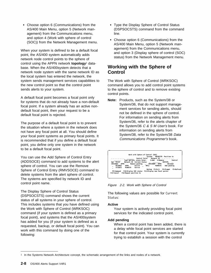
� Choose option 6 (Communications) from theAS/400 Main Menu, option 5 (Network man-agement) from the Communications menu,and option 4 (Work with sphere of control(SOC)) from the Network Management menu.
When your system is defined to be a default focalpoint, the AS/400 system automatically addsnetwork node control points to the sphere ofcontrol using the APPN network topology 1 data-base. When the AS/400system detects that anetwork node system with the same network ID asthe local system has entered the network, thesystem sends management services capabilities tothe new control point so that the control pointsends alerts to your system.
A default focal point becomes a focal point onlyfor systems that do not already have a non-defaultfocal point. If a system already has an active non-default focal point, then your request to be adefault focal point is rejected.
The purpose of a default focal point is to preventthe situation where a system in the network doesnot have any focal point at all. You should defineyour focal point systems as primary focal points. Itis recommended that if you define a default focalpoint, you define only one system in the networkto be a default focal point.
You can use the Add Sphere of Control Entry(ADDSOCE) command to add systems to the alertsphere of control. You can use the RemoveSphere of Control Entry (RMVSOCE) command todelete systems from the alert sphere of control.The systems are specified by network ID andcontrol point name.
The Display Sphere of Control Status(DSPSOCSTS) command shows the currentstatus of all systems in your sphere of control.This includes systems that you have defined usingthe Work with Sphere of Control (WRKSOC)command (if your system is defined as a primaryfocal point), and systems that the AS/400systemhas added for you (if your system is defined as arequested, backup, or default focal point). You canwork with this command by doing one of thefollowing:
� Type the Display Sphere of Control Status(DSPSOCSTS) command from the commandline.
� Choose option 6 (Communications) from theAS/400 Main Menu, option 5 (Network man-agement) from the Communications menu,and option 3 (Display sphere of control (SOC)status) from the Network Management menu.
Working with the Sphere ofControl
The Work with Sphere of Control (WRKSOC)command allows you to add control point systemsto the sphere of control and to remove existingcontrol points.
Note: Products, such as the System/38 orSystem/36, that do not support manage-ment services for sending alerts, shouldnot be defined in the sphere of control.For information on sending alerts fromSystem/36, refer to the alerts chapter ofthe System/36 C & S M User's book. Forinformation on sending alerts fromSystem/38, refer to the System/38 DataCommunications Programmer's book.
à ðWork with Sphere of Control (SOC)
System: ROCHESTR Position to . . . . . . . . ________ Control Point Network ID . . . . . . . . ________ Type options, press Enter. 1=Add 4=Remove ControlOpt Point Network ID Current Status _ ________ \NETATR_ _CHICAGO1 APPN Remove pending _ CHICAGO2 APPN Revoked_ MILWKEE APPN Active _ MPLS MINNSTA Add pending_ STLOUIS MINNSTA Active
Bottom F3=Exit F4=Prompt F5=RefreshF9=Command F1ð=Display SOC status F11=Display new focal points
F12=Cancel F16=Repeat position to
á
ñ
Figure 2-2. Work with Sphere of Control
The following values are possible for CurrentStatus:
ActiveYour system is actively providing focal pointservices for the indicated control point.
Add pendingWhen a control point has been added, there isa delay while focal point services are startedfor that control point. Your system is currentlytrying to establish a session with the control
1 In the Systems Network Architecture concept, the schematic arrangement of the links and nodes of a network.
2-8 OS/400 Alerts Support V4R1

point so that it can provide focal point ser-vices.
InactiveYour system is not currently providing focalpoint services for the indicated control point.The control point cannot communicate withyour system now because of a lost con-nection. If a control point with this status isremoved from your system's sphere of control,it is not displayed.
Never activeYour system has never provided focal pointservices for the indicated control point. Thecontrol point has never sent alerts to yoursystem. If a control point with this status isremoved from your system's sphere of control,it is not displayed.
RejectedThe indicated control point does not requirefocal point services from your system. It islikely that the control point has a differentfocal point. If a control point with this status isremoved from your system's sphere of control,it is not displayed.
Remove pendingYour system is providing focal point services,but a user has removed the control point fromthe sphere of control. The control point isremoved from the sphere of control whenanother system starts focal point services forthe control point or the session is lost.
RevokedThe indicated control point is no longer in yoursystem's sphere of control. A new focal pointis now providing focal point services for thecontrol point. The new focal point is identifiedin the New Focal Point column. Press F11 todisplay new focal points. If a control point withthis status is removed from your system'ssphere of control, it is not displayed.
The CL Reference book contains more informationabout the WRKSOC command.
Adding a System to the Sphere ofControl: On the Work with Sphere of Control(SOC) display, you can use option 1 (Add) to adda system to your sphere of control.
You can also use the Add Sphere of Control Entry(ADDSOCE) command to add systems to the alertsphere of control.
To add a system to the sphere of control, type thecontrol point name and the network ID of thesystem. For the AS/400 system, these are thelocal control point name (LCLCPNAME), and thelocal network ID (LCLNETID) network attributes ofthe system you wish to add to the sphere ofcontrol.
When you add a control point to the sphere ofcontrol, and your system is defined to be aprimary focal point, the AS/400 system sendsmanagement services capabilities to the newcontrol point so your AS/400 system can be afocal point for that system. This results in one ofthe statuses described in “Working with theSphere of Control” on page 2-8 being displayed.
If you use option 1 (to add a control point name),but do not enter the name, you will see the fol-lowing display. If you use option 1 and enter thename on the Work with Sphere of Control display,the system is added.
à ðAdd Sphere of Control Entry
System: ROCHESTR
Type choices, press Enter
Network ID . . . . . . . . \NETATR_
Control point . . . . . . ________
Removing Systems from the Sphere ofControl: Use option 4 (Remove) from theWork with Sphere of Control display to remove acontrol point from your sphere of control.
You can also use the Remove Sphere of ControlEntry (RMVSOCE) command to remove systemsfrom the alert sphere of control.
A control point in the sphere of control should notbe removed from the sphere of control untilanother focal point has started focal point servicesto that system. This ensures that a system alwayshas a focal point. When a control point isremoved, it goes into a remove pending condition
Chapter 2. Setting Up OS/400 Alert Support 2-9

until an operator at another focal point systemadds the control point to its sphere of control,allowing it to act as the focal point for the removedcontrol point, or until the connection to that systemis lost.
The recommended method of removing a systemfrom the sphere of control is as follows:
1. Define another system in the network to be aprimary focal point.
2. The network operator at the new focal pointshould add the system you want removedfrom your sphere of control into the new focalpoint's sphere of control.
3. The new focal point takes over as focal pointfor the system that you want to be removed.
4. Wait until the system that you want to removehas a status of Revoked.
5. The system can now be removed from yoursphere of control.
Displaying the Sphere of ControlStatus
The Display Sphere of Control Status(DSPSOCSTS) command displays the status of allsystems that are currently in your system's sphereof control. This display shows systems you havedefined in your sphere of control using theWRKSOC command and also systems the AS/400system has defined in your sphere of controlbecause your system is a default, requested, andbackup focal point for those systems.
à ð System: ROCHESTR
Position to . . . . . . . . ________ Control Point
Network ID . . . . . . . . ________
Type options, press Enter.
5=Display
Control Type of
Opt Point Network ID Services Current Status
_ CHICAGO1 APPN Primary Remove pending
_ CHICAGO2 APPN Primary Revoked
_ MILWKEE APPN Primary Active
_ MPLS MINNSTA Requested Active
_ GRNBAY1 NRTHWI Default Active
_ GRNBAY2 NRTHWI Default Active
_ GRNBAY3 NRTHWI Default Active
_ GRNBAY4 NRTHWI Default Active
_ GRNBAY5 NRTHWI Default Add pending
F3=Exit F5=Refresh F6=Print F11=Display new focal points
F12=Cancel F16=Repeat position to
á
ñ
If the system is currently defined as a focal point(either primary or default), the following values arepossible for Current Status:
ActiveYour system is actively providing focal pointservices for the indicated control point.
Add pendingWhen a control point has been added, there isa delay while focal point services are startedfor that control point. Your system is currentlytrying to establish a session with the controlpoint so that it can provide focal point ser-vices.
InactiveYour system is not currently providing focalpoint services for the indicated control point.The control point cannot communicate withyour system now because of a lost con-nection.
Never activeYour system has never provided focal pointservices for the indicated control point. Thecontrol point has never sent alerts to yoursystem.
RejectedThe indicated control point does not requirefocal point services from your system. It islikely that the control point has a differentfocal point.
Remove pendingYour system is providing focal point services,but a user has removed the control point fromthe sphere of control. The control point isremoved from the sphere of control whenanother system starts focal point services forthe control point or the session is lost.
RevokedThe indicated control point is no longer in yoursystem's sphere of control. A new focal pointis now providing focal point services for thecontrol point. The new focal point is identifiedin the New Focal Point column. Press F11 todisplay new focal points.
The CL Reference book contains more informationabout the DSPSOCSTS command.
2-10 OS/400 Alerts Support V4R1

Additional Considerations
The following topics are discussed:
� Nested focal points
� Looping considerations
� Held alerts
� Switched line considerations
� Management services sessions
� Alert controller session
� Alert support through an SNA subareanetwork
� Interconnected network considerations
� Performance considerations
Nested Focal Points
A nested focal point is a focal point that is definedin the sphere of control of another focal point. Anested focal point forwards all received alerts toits focal point. By nesting focal points, alerts canbe concentrated into one system in part of anAPPN network and then forwarded.
There are advantages and disadvantages tonesting focal points.
� Advantages
– A focal point can be configured so thatalerts are routed through fewer APPNnetwork nodes between that focal pointand the systems in its sphere of control.
– There are fewer management servicessessions at any given system. This distrib-utes focal point processing, such assession establishment and retries amongmore systems.
� Disadvantages
– The management for the sphere of controlis performed at more than one system.
Looping Considerations
When configuring a network for sending alerts, itis possible to create a looping condition.Figure 2-3 on page 2-12 shows a network wherealerts will loop.
SYSA is in the sphere of control of SYSB, SYSBis in the sphere of control of SYSC, and SYSC isin the sphere of control of SYSA. SYSA sendsalerts to SYSB, SYSB sends alerts to SYSC, andSYSC sends alerts to SYSA. An alert created atSYSA would be sent through SYSB and SYSC,and would eventually be sent back to SYSA. Thisalert would be forwarded continuously throughthese three systems.
The OS/400 alert support provides a way toprevent a looping condition. When a loop isdetected, a focal point is revoked to dissolve theloop. The last focal point established, whichresulted in the loop, is revoked. For migration con-cerns about looping conditions, refer toAppendix D, Migration Concerns.
Held Alerts
Held alerts are alerts that could not be sentbecause of network conditions or theALRHLDCNT network attribute and are beinglogged until they can be sent later. Alerts are heldonly when one of the following is true:
� A focal point has added this system to itssphere of control (a message is sent to thissystem's QSYSOPR message queue) andcontact is established and lost with that focalpoint since the last initial program load (IPL).
� The NODETYPE network attribute is set to*ENDNODE and contact is established andlost with the serving network node since thelast IPL.
� The ALRCTLD network attribute is not set to*NONE and contact is established and lostwith this controller since the last IPL.
� The ALRHLDCNT network attribute is set to avalue that is greater than 0 and the number ofalerts processed is set to a value that is lessthan the alert hold count. The ALRHLDCNTonly applies if the alerts are being sent usingan alert controller session.
A message is sent to the QSYSOPR messagequeue when the system starts to hold alerts.Another message is sent when contact is estab-lished again and alerts can be sent. For migrationconcerns about held alerts, refer to Appendix D,Migration Concerns.
Chapter 2. Setting Up OS/400 Alert Support 2-11

SYSC SYSA
SYSB
SYSB
SYSC
SYSA
RV2P906-0
Sphere of Control Sphere of Control
Sphere of Control
Figure 2-3. Looping Condition Created When Sending Alert
You can use the Work with Alerts (WRKALR)command and specify *HELD for the displayoption parameter to see the alerts that are cur-rently held:
WRKALR DSPOPT(\HELD)
After the held alerts are sent, they are no longershown when you specify *HELD for the displayoption parameter. Alerts that are held are loggedeven if the ALRLOGSTS network attribute wouldotherwise prevent them from being logged. See“Logging Held Alerts” on page 3-13 for more forinformation about logging held alerts.
When the held alert is sent, it remains logged onlyif the ALRLOGSTS network attribute indicates itshould.
There is also a Held alert flag on the Alert Detaildisplay. This flag is Yes if the alert has ever beenheld. This flag remains Yes even after the heldalert has been sent. You can compare theProblem date/time with the Logged date/time onthe Alert Detail display to estimate how long thealert was held.
See “Working with Logged Alerts” on page 3-14for more information about the Alert Detail dis-plays.
Switched Line Considerations
How the AS/400 system handles switched lines foralerts depends on the type of session used (man-agement services session or alert controllersession).
Management Services Session
Alert support on a switched line is dependent onthe way APPN uses switched lines. A switchedline is not activated for the sole purpose ofsending an alert.
Alerts flow between an end node and its servingnetwork node on the CPSVCMG reserved modesession. If this session is active on a switchedline, the switched line does not automatically dis-connect. If this session is not active, alerts cannotbe sent.
Alerts flow between a network node and its focalpoint on the SNASVCMG reserved mode session.The SNASVCMG session normally passesthrough transmission groups (TGs) , groups oflinks between directly attached nodes appearingas a single logical link for routing messages, thatare control point session capable (CPSSN(*YES)on the controller description). If there is no paththat passes through only control point sessioncapable TGs, then alerts cannot be sent to thefocal point. A switched transmission groupbetween two network nodes that is control pointsession capable does not automatically discon-nect.
The APPN Support book contains more informa-tion about transmission groups.
Management Services SessionRetries: If the management services sessionbetween a node and its focal point goes down, thefocal point changes the status of that node toInactive. Whenever the status of a transmissiongroup (TG) changes in the APPN network, thefocal point tries to establish sessions again with all
2-12 OS/400 Alerts Support V4R1

network nodes in the sphere of control that have astatus of Inactive.
Note: Many retries may occur if your system is adefault focal point or as a primary focalpoint with many systems in the sphere ofcontrol.
If the system is a primary focal point, you mayforce a retry for systems in the sphere of controlby removing the system from the sphere of controland then adding it back. You can do this using theWork with Sphere of Control (WRKSOC)command or with the Remove Sphere of ControlEntry (RMVSOCE) and the Add Sphere of ControlEntry (ADDSOCE) commands.
If the system is a default focal point, you cannotforce a retry.
Focal points automatically attempt to retry primaryand default focal point services. However, thisdoes not include primary focal point services forend nodes and nodes in an Interconnect network.End points automatically retry requested focalpoint services. Nodes as end points in an Inter-connect network retry primary focal point services.
Note: The CPSVCMG reserved mode session isused by APPN to notify other systems ofchanges in status. If no CPSVCMGreserved mode session is present, noretries can be done.
Alert Controller Session
When using the alert controller session (ALRCTLDnetwork attribute) over a switched line, the OS/400alert support will establish the switched connectionand send alerts when the alert hold count(ALRHLDCNT) network attribute value isexceeded. The controller description must havebeen varied on for the connection to be estab-lished. Also, there must be an APPC device forthe controller description that has been varied on.The alert support will attempt to establish theswitched connection using the first APPC devicefound for the controller description that is variedon.
The APPC device is not used to establish anAPPC conversation. It is only needed to establishthe switched connection. You do not need to con-figure an APPC device at the remote system.Once the connection is established, the alert
support will send all of the held alerts. It is impor-tant to note that the alert controller session doesnot use an APPC session, and will not automat-ically drop the switched connection when all of thealerts have been sent. The only control over drop-ping the switched connection is through use of theswitched disconnect (SWTDSC) and disconnecttimer (DSCTMR) values in the ALRCTLD con-troller description.
The Switched Disconnect (SWTDSC) value shouldbe *YES. Once the connection is made, the linkwill remain active for the number of seconds spec-ified by the disconnect timer (DSCTMR) value.The DSCTMR value should be large enough toallow alert support to send all of the held alerts.There is a relationship between the alert holdcount network attribute and the disconnect timervalue. If the alert hold count value is large, thedisconnect timer value should also be large. Thedisconnect timer value should not be 0 or the con-nection will never drop, unless another applicationis using the connection and unbinds a session.Alert support does not bind or unbind a sessionwhen the alert controller session is used forsending alerts.
After the switched connection has been active forthe number of seconds specified by the discon-nect timer value, the connection is dropped, evenif all of the alerts have not been sent. Theremaining alerts and all new alerts are held untilthe alert hold count value is again exceeded. Theactual time required to send one alert depends onseveral factors such as system load, and modemand link characteristics. You may want to exper-iment with disconnect timer values to get thesmallest value possible while still sending the heldalerts.
Alerts are sent without regard to the ALRHLDCNTattribute if the switched line is active for someother reason. If the switched line is not active,alerts are held until the specified alert hold countis reached or until the switched line connection ismade by another application. If the control of theswitched line by the ALRCTLD controllerdescription does not meet your needs, you maywant to consider writing your own application tocontrol the switched line connection and discon-nection. Other applications could be:
� Display station pass-through
� Distributed data management (DDM)
Chapter 2. Setting Up OS/400 Alert Support 2-13

� SNA distribution services (SNADS) timed dis-tributions
For example, starting display station pass-throughover a switched line will cause the switched con-nection to be made, and held alerts will be sent.You should set the alert hold count network attri-bute to *NOMAX in this case, so the alert supportwill not establish the switched connection.
Alert Support through an SNASubarea Network
Figure 2-4 shows an advanced peer-to-peer net-working (APPN) network interacting with asubarea network where the host support includes:
� Virtual Telecommunications Access Method(VTAM*) Version 3, Release 2 program
Note: If releases of the VTAM programbefore Version 3, Release 2 are used,the AS/400 system is configured as adependent logical unit and the sphereof control support does not functioncorrectly.
� Advanced Communications Facility/NetworkControl Program (ACF/NCP) Version 4,Release 3
The alerts SNASVCMG reserved mode session issupported through the SNA subarea network forthis configuration.
There is no CPSVCMG reserved mode sessionbetween network node A (NNA) and network nodeB (NNB). Therefore, for NNB to find NNA in itssphere of control, NNB must define a remotelocation list entry showing that NNA can beaccessed through VTAM/NCP. Also, NNA mustdefine a remote location list entry for NNB.
NNB must be defined as the primary focal pointfor NNA.
Since there is no CPSVCMG reserved modesession between NNA and NNB, retries are per-formed by the entry point, NNA. NNA must beadded to the sphere of control when connection ispossible. Once active, NNA performs the retry.
Note: The alert controller session is not sup-ported across the subarea (ALRCTLDparameter of the CHGNETA command).
VTAM/NCPV3R2
NNA
NNB
SubareaNetwork
Primary Focal PointSphere of ControlIncludes NNA
RSLL005-4
Figure 2-4. APPN Subarea Network
Interconnected NetworkConsiderations
If you are using APPN, it is possible to connectnetworks that have different network IDs.
Nodes with network IDs that are different from thelocal node will not have retry performed by thefocal point when placed in the sphere of control.Retries are performed by entry point systems. Ifyou have a configuration similar to Figure 2-5 onpage 2-15 where the nodes have differentnetwork IDs, it is recommended that you nestfocal points. For example, in Figure 2-5 onpage 2-15, it is recommended that NET2.D benested with NET2.E and NET2.F in the sphere ofcontrol. In this example, NET1.A is a focal point,with NET1.B, NET1.C, and NET2.D in the sphereof control.
Performance Considerations
Alert throughput on the alert controller sessiondecreases if high priority data is sent on the samelink.
If many alerts are sent on a system or receivedfrom other systems, there may be a delay in thelogging of the alerts.
A primary focal point with a large sphere of controlmay require significant processing to try to estab-lish sessions again. This is especially true if thereis much link activation/deactivation occurring in thenetwork. By using nested focal points, the size ofany particular sphere of control can be reduced.
2-14 OS/400 Alerts Support V4R1

Node A
Network 1 Network 2
Node B
Node C
Node D
Node E
Node F
Focal Point
Focal Point
RV2P901-1
Figure 2-5. Interconnected Network
Each network should have only one default focalpoint. A default focal point serves as a focal pointfor systems in the network that do not already
have a primary focal point. Having more than onedefault focal point in the network does not provideany additional benefit.
Chapter 2. Setting Up OS/400 Alert Support 2-15

2-16 OS/400 Alerts Support V4R1

Chapter 3. Using OS/400 Alert Support
This chapter describes how to use OS/400 alertsupport for working with message descriptions,alert tables, and alert descriptions.
OS/400 Alerts
The AS/400 system creates an alert when analertable message is sent to the local systemoperator. An alertable message is any messagewith the alert option field, located in the messagedescription, set to a value other than *NO. Youcan change this value using the Change MessageDescription (CHGMSGD) command. In this way,you can select the messages for which you wantalerts sent to a network operator at a focal point.IBM-supplied OS/400 messages are shipped withthe system in the QCPFMSG message file.
A subset of OS/400 messages are defined asalertable. Most OS/400 messages are notalertable. For a list of which QCPFMSG messagesare alertable, see Appendix B, IBM-SuppliedAlertable Messages.
Besides changing the alert option field forIBM-supplied messages, you can:
� Create your own messages.
� Define your own messages as alertable.
� Create your own alerts using the QALGENAAPI. Refer to the System API Reference bookfor information about the QALGENA API.
For more information on defining your own mes-sages, see the CL Programming book. To definealerts for your messages by creating alert tablesand alert descriptions, see Appendix A, SampleProcedures for OS/400 Alerts.
The following application program interfaces(APIs) allow alerts to be created, sent, andretrieved:
� Generate Alert (QALGENA) API creates analert for a message ID and returns it to thecalling program.
� Send Alert (QALSNDA) API sends a SystemsNetwork Architecture (SNA) generic alert tothe OS/400 alert manager for processing.
� Retrieve Alert (QALRTVA) API retrieves analert from the alert database for processing bythe application.
Refer to the System API Reference book for moreinformation about alert APIs.
There are several factors to consider whendeciding whether a message should be alertable.You should consider the following questions whendeciding whether an alert should be sent for a par-ticular error:
� Do you want the system to send any alerts?
� Is the system running attended or unat-tended?
� Is local problem analysis available for theproblem?
� Does problem analysis provide a local resol-ution to the problem?
� Do you want to send an alert to report theoutcome of problem analysis?
Working with OS/400 MessageDescriptions
The Add Message Description (ADDMSGD)command or the Change Message Description(CHGMSGD) command is used to specify whethera message will cause an alert to be created. AllOS/400 messages contain an alert option. Thesystem is shipped with the alert options in allsystem messages set to a specific default that youcan change. You can also specify the alert optionon messages that you create.
Alert Option: The alert option (ALROPT)parameter in the message description is made upof two parts, the alert type and the resourcename variable . These two parts are separated bya blank when the parameter is specified in theChange Message Description (CHGMSGD)command.
Alert Type: The alert type is the value in themessage description that determines if themessage is alertable or not. The following valuescan be specified for the alert type:
Copyright IBM Corp. 1997 3-1

*IMMEDThis value causes an alert to be createdimmediately, at the same time that themessage is sent to the local system operator.
Most messages defined as *IMMED arecaused by a program failure.
*DEFERThis value causes an alert to be created afterlocal problem analysis. *DEFER is specifiedonly for messages that are qualified forproblem analysis. This is determined by thelog problem (LOGPRB) parameter in themessage description.
Messages that are qualified for problem anal-ysis are caused by equipment failures suchas:
� Tape or diskette
� Display stations
� Printers
� Lines or modems
If you specify this value for a message forwhich problem analysis is not available, thisvalue is treated as if you had specified*IMMED. When the system is operating inunattended mode, all alerts set to *DEFER aretreated as *IMMED.
*UNATTENDThis value causes an alert to be created atthe time that the message is sent to the localsystem operator message queue, but onlywhen the system is unattended. The system isunattended when the alert status (ALRSTS)network attribute is set to *UNATTEND.
For all operator intervention messages, thenormal setting of the alert type is *UNAT-TEND. This includes but is not limited to thefollowing:
� Device door or cover open
� Printer out of paper or paper jammed
� Tape or diskette required
� Power for local device turned off
*NOThis value specifies that no alert is to becreated for the message.
Note: The alert type in the message descriptionis not related to the alert type on the Workwith Alerts displays. See “Working withLogged Alerts” on page 3-14 for informa-tion about working with alerts.
Resource Name Variable: The resource namevariable identifies the name of the failing resourcein the message. The failing resource is the lowestlevel (most remote) resource that is common to allresources whose actual or impending loss is thecause of the alert. It is identified as the last entrydisplayed in the resource hierarchy in the DisplayAlert Detail and Display Recommended Action dis-plays of the Work with Alerts (WRKALR)command. The resource hierarchy identifies thenames of all the resources that provide a con-nection to the failing resource, plus the name ofthe failing resource itself.
The resource name variable is a number from 1 to99 that is the number of the substitution variablein the message data containing the name of thefailing resource. The name of the resource isplaced in the substitution variable by the systemwhen the message is sent to the QSYSOPRmessage queue.
There are certain values for the resource namevariable that are defined by the system to identifyspecific resource types that the system knows.These reserved values are identified in Table 3-1on page 3-3, along with the resource types thatcan be associated with each particular reservedvalue.
An example of a message that uses a resourcename variable of 23 is:
Line &23 failed. Recovery stopped.
In this example, the name of the resource passedin the message data for substitution is the nameof a line description defined on the system. Thisname is sent in the alert as the name of the failingresource. The resource type displayed with thename is link (LNK).
Substitution Variables: The resource types thatcan be associated with each substitution variableshown in Table 3-1 on page 3-3 are defined asfollows:
3-2 OS/400 Alerts Support V4R1

Line description This is the name of a linedescription created by a create linedescription command. See the Com-munications Configuration book for thecreate line description commands.
Controller description This is the name of a con-troller description created by a createcontroller description command. Seethe Communications Configurationbook for the create controllerdescription commands.
Device description This is the name of a devicedescription created by a create devicedescription command. See the Com-munications Configuration book for thecreate device description commands.
First level resource This is the name of the phys-ical resource (usually an input/outputprocessor) that is associated with thefailing resource and closest to thesystem processor.
Second level resource This is the name of thephysical resource that is associatedwith the failing resource and second
closest to the system processor. Thetype of resource named by this variabledepends on the type of subsystem asshown in Table 3-1.
Third level resource This is the name of thephysical resource that is associatedwith the failing resource and thirdclosest to the system processor. Thetype of resource named by this variabledepends on the type of subsystem asshown in Table 3-1.
Fourth level resource This is the name of thephysical resource that is associatedwith the failing resource and is thefourth closest to the system processor.The type of resource named by thisvariable depends on the type of sub-system as shown in Table 3-1.
Network interface description This is the nameof a network interface descriptioncreated by the Create Network Inter-face Description (CRTNWIISDN)command. Refer to the ISDN Supportbook for more information.
Table 3-1. Resource Name Variables Defined by the System
Variable Description
Resource Type Com-munications Sub-system
Resource TypeStorage Sub-system
Resource TypeWork Station Sub-system
23 Line description LNK, BCH N/A N/A24 Controller description CTL N/A CTL, LC25 Device description N/A TAP, DKT DSP, PRT26 First level resource LC LC LC27 Second level resource ADP ADP DSP, PRT28 Third level resource POR DSK, DKT, TAP N/A29 Fourth level resource BCH N/A N/A30 Network interface
descriptionDCH N/A N/A
30 Network serverdescription
SVR N/A N/A
Note: See Table 3-5 on page 3-16 for a list ofthe resource type abbreviations.
Alert Hierarchy: Only one number is defined forthe resource name variable, but if this number isknown by the system, a complete hierarchy, whichincludes an entry for each resource in the hier-archy, is built by the system, starting from thename of the failing resource up through the nameof the system itself. For example, if the resourcename variable is defined in the message
description as 28, and the failing resource is acommunications port, the resource hierarchy pro-vided by the system has the following entries:
System name This is the name of the system thatdetected the problem. The resourcetype is control point (CP).
Note: The name that the AS/400system uses for the systemname is the local control point
Chapter 3. Using OS/400 Alert Support 3-3

name (LCLCPNAME) networkattribute.
Input/output processor This is the name of theI/O processor on which the failing portis located. The resource type is localcontroller (LC).
Input/output adapter This is the name of theadapter card on which the failing port islocated. The resource type is adapter(ADP).
Port This is the resource name for thefailing port. The resource type is port(POR).
If a resource name variable is outside the range ofvalues defined by the system, the name specifiedas the substitution data for the identified variableis sent in the alert as the failing resource, and isidentified with a resource type of unknown (UNK)when the resource hierarchy is displayed. Forexample, if the message text for the alertablemessage is:
Error detected for tape &1.
and the name of the resource passed in themessage data for substitution variable 1 is TAPE1,the name of the failing resource in the alert isTAPE1 and the resource type is UNK.
If there is no value specified for the resourcename variable, or if the value is 0, the systemlocal control point name is sent in the alert as thename of the failing resource.
Changing the Alert Options: The fol-lowing example shows changing the alert optionsfor message CPA5339 so that an alert is alwayscreated by the system when this message is sentto the local system operator.CHGMSGD MSGID(CPA5339) MSGF(QSYS/QCPFMSG) ALROPT(\IMMED 1)
The name specified for substitution variable &1;will be used as the failing resource.
The CL Reference book contains additional infor-mation about the Change Message Description(CHGMSGD) command.
Alerts and Local ProblemAnalysis
Problems detected by the system are reportedlocally by messages sent to the QSYSOPRmessage queue. Some of these messages haveproblem analysis procedures associated with themthat can be run locally by the system operator.Messages that have problem analysis proceduresshipped with the system have the log problem(LOGPRB) parameter in the message descriptionset to *YES. These messages can be identifiedwhen they are displayed at the QSYSOPRmessage queue by the asterisk (*) precedingthem. When you see a message preceded by anasterisk, you can do local problem analysis bypressing F14 (Run problem analysis) with thecursor positioned on the message. You can alsorun the problem analysis routines using the Workwith Problems (WRKPRB) command.
In a network, you can report problems by sendingalerts to a focal point. The network operator atthe focal point is responsible for handling thereported problems. This focal point system maynot be at the same location as the system that ori-ginally detected and reported the problem.
You can set up your network so that you can dothe appropriate problem analysis either at thereporting location or at a central site that is theproblem management focal point. The problemmanagement focal point is the management ser-vices responsible for the problem analysis anddiagnosis for a sphere of control. At times, youmay want problem analysis done at the failinglocation but the service call or repair action con-trolled by a central site. In other cases, because ofthe type of problem or the ability to handle theproblem at a particular location, you may wantboth the problem analysis and the repair actioncontrolled by a single location.
By appropriately setting the alert status (ALRSTS)network attribute for the system and the alertoption (ALROPT) parameter of the messagedescription for the message that reports theproblem, you can tailor your network to use alertsin any of the following ways:
� Handle the problem at the system with theproblem.
3-4 OS/400 Alerts Support V4R1

� Analyze the problem at the system with theproblem but start recovery procedures at thefocal point system.
� Handle the problem at the focal point system.
� Handle the problem at the focal point systemonly when the system with the problem isunattended.
� Handle problems differently depending on thetype of problem.
Table 3-2 shows the relationship between thealert option (ALROPT) parameter in the messagedescription and the alert status (ALRSTS) networkattribute. In this figure, the messages defined as*DEFER have the log problem (LOGPRB) param-eter in the message description set to *YES;setting the LOGPRB parameter to *NO in amessage causes all alerts for that message to betreated as *IMMED.
Table 3-2. Relationship between Alert Status Network Attribute and Alert Option Parameter
Network Attribute
ALROPTParameter inMessageDescription
*IMMED *DEFER *UNATTEND *NOALRSTS(*ON) Alert Alert after local problem
analysisNo alert No alert
ALRSTS(*UNATTEND) Alert Alert Alert No alertALRSTS(*OFF) No alert No alert No alert No alert
In this figure, Alert means an alert is createdimmediately, No alert means that no alert iscreated, and Alert after local problem analysismeans that an alert is created after problem anal-ysis is attempted for the problem.
When there are local problem analysis routinesavailable for a problem that has been reported toa remote problem management focal point with analert, you can run problem analysis remotely usinghost command facility (HCF) or display stationpass-through. You can use the Problem date/time
on the Display Alert Detail display to locate theproblem in the problem log at the reporting sitewith the same date and time. You can use theWork with Problems (WRKPRB) command to findproblems in the problem log. You can also useSystemView* System Manager/400, an optionallicensed program, to work with the problem log.
See “Working with Logged Alerts” on page 3-14for more information about the Display Alert Detaildisplays.
When you work with problems, you can tell if analert has been sent or will be sent by looking atthe Problem Detail display for the problem you areworking with. A problem that is alertable is dis-played with Alertable condition set to Yes. IfAlert pending is Yes, an alert is sent automat-ically after problem analysis has been run, unlessit is determined that the problem no longer exists.
If Alertable condition is Yes, and Alert pending
is No, an alert has already been sent because theproblem analysis routines have already been run.
If an alert has been sent by the system afterproblem analysis, you may choose to sendanother alert before exiting problem analysis bypressing F9 (Send alert). You may want to do thisif you have obtained different results by runningthe problem analysis routines the second time.
Use the Analyze Problem (ANZPRB) command forproblems that you detect, but that the system hasnot reported. From the following displays, you canprepare service requests, send an alert, or both.
Refer to online information for more details onworking with problems and local problem analysis.
Alert Messages for General Use
Message CPI9806 is a predefined alertablemessage in the QCPFMSG message file. Thismessage is sent using the Send ProgramMessage (SNDPGMMSG) command. MessageCPI9806 is an operator-generated alert in theQCPFMSG alert table.
Message CPI9806 contains two substitution vari-ables. The first 8 bytes contain the user-definedname that identifies the alert when the alert is
Chapter 3. Using OS/400 Alert Support 3-5

generated. This name can be the name for yoursystem. In the following example, ROCHESTR isused as the user-defined name. The second vari-able is the message text, which can be up to 100characters. Use the message text to describe thecondition that the alert is reporting.
The following is an example of the command usedto send CPI9806 with an operator-definedmessage text:
SNDPGMMSG MSGID(CPI98ð6) MSGF(QCPFMSG) MSGDTA('ROCHESTR We are +
experiencing performance problems in Rochester')
TOMSGQ(QSYSOPR)
The Send Program Message (SNDPGMMSG)command can be used only from a CL program.The following is an example of a batch job tocreate a CL program and a command calledSNDALR. The SNDALR command, when issuedby the operator, is processed by the SNDALRprogram (which issues the SNDPGMMSGcommand).
To submit the job, use the Submit Database Job(SBMDBJOB) command.//BCHJOB CRTSNDALR LOG(4 ðð \SECLVL)
CRTCLPGM QGPL/SNDALR SRCFILE(FILEððð1)
//DATA FILE(FILEððð1) FILETYPE(\SRC)
PGM (&RESOURCE &MSGTEXT);
DCL &RESOURCE \CHAR 8
DCL &MSGTEXT \CHAR 1ðð
DCL &MSGDATA \CHAR 1ð8
CHGVAR &MSGDATA (&RESOURCE || &MSGTEXT);
SNDPGMMSG MSGID(CPI98ð6) MSGF(QCPFMSG) MSGDTA(&MSGDATA); +
TOMSGQ(QSYSOPR)
ENDPGM
//
CRTCMD QGPL/SNDALR PGM(QGPL/SNDALR) SRCFILE(FILEððð2) +
TEXT('Send Operator Generated Alert')
//DATA FILE(FILEððð2) FILETYPE(\SRC)
CMD PROMPT('Send Operator Generated Alert')
PARM KWD(RESOURCE) EXPR(\YES) MIN(1) MAX(1) +
TYPE(\CHAR) LEN(8) PROMPT('Resource name')
PARM KWD(TEXT) EXPR(\YES) MIN(1) MAX(1) +
TYPE(\CHAR) LEN(1ðð) PROMPT('Alert message text')
//
//ENDBCHJOB
Message CPI9805 (in the QCPFMSG messagefile) is also reserved for your use. CPI9805 is auser application alert in the QCPFMSG alert table.CPI9805 has the same message format asCPI9806.
Message CPI9804 (in the QCPFMSG messagefile) is reserved for use by IBM applications.CPI9804 is an IBM application alert in theQCPFMSG alert table. CPI9804 has the sameformat as CPI9806.
The alert option parameter for these messages is:
ALROPT(\IMMED 1)
Operator-Generated Alerts
Operator-generated alerts can be sent to reportproblems that you detect, but that the system hasnot reported. They can also be used to reportadditional information about a problem detected bythe system.
Operator-generated alerts are created by usingthe Analyze Problem (ANZPRB) command or byselecting option 2 (Work with problems) on theProblem Handling menu, and then pressing F14(Analyze new problem) on the Work with Prob-lems display.
You can analyze the problem and place a call forservice in addition to sending an alert for theproblem.
If you just want to send an operator-generatedalert, do the following:
1. Enter the ANZPRB command.
2. From the Analyze a Problem display, selectthe option that is most appropriate.
3. The system shows a number of displays foryou to define the problem. Select the optionfor each display that is most appropriate foryour problem.
4. After you enter the options to define theproblem, a Report Problem display is shown.
5. Select option 1 (Send alert) to send an alert.Another display allows you to enter themessage that you want to send in the alert.
6. If you are sending an alert to provide moreinformation about a problem that the systemdetected, include the date, time, and themessage code (if available) that are shown inthe problem record for the problem. See“Alerts and Local Problem Analysis” onpage 3-4 for information on how to find thisinformation.
7. After you have entered your message, pressthe Enter key.
8. The alert is created and you are returned tothe display that was shown before theANZPRB command was entered.
3-6 OS/400 Alerts Support V4R1

Application-Generated Alerts
Application created alerts can be created eitherby:
� Sending an alertable application message tothe QSYSOPR message queue or to theQHST log. Refer to Appendix A, Sample Pro-cedures for OS/400 Alerts for more informa-tion.
� Or using the alert APIs (QALGENA andQALSNDA) to allow your application to createalerts and notify the OS/400 alert manager ofpreviously created alerts that need to behandled. Refer to the System API Referencebook for information about the alert APIs.
Creating an Alert Table
To create your own OS/400 alerts, you must firstcreate an alert table for the alert descriptions. Usethe Create Alert Table (CRTALRTBL) command tocreate the alert table. You then use the Add AlertDescription (ADDALRD) command to describeyour alerts and place them in the alert table, asdescribed in “Adding Alert Descriptions to an AlertTable” on page 3-8.
The following parameters are supported by theCreate Alert Table (CRTALRTBL) command:
ALRTBL ParameterSpecifies the name of the alert table that iscreated. An alert table has a one-to-one corre-spondence with a message file. To define analert for a particular message, the name of thealert table must be the same as the name ofthe message file.
The alert table and message file do not haveto be in the same library. However, the alerttable library must be in the library list of thejob that causes the alert to be created.
*CURLIB: The current library is used to locatethe alert table. If no library is specified as thecurrent library for the job, the QGPL library isused.
library-name: Specify the library where thealert table is to be created.
alert-table-name: Specify the name of the alerttable that is created.
AUT ParameterSpecifies the authority granted to users whodo not have specific authority to the object,are not on the authorization list, or whosegroup has no specific authority to the object.
*LIBCRTAUT: The public authority for theobject is taken from the CRTAUT keyword ofthe target library. The CRTAUT value is deter-mined when the object is created. If theCRTAUT value for the library changes afterthe object is created, the new value does notaffect any existing objects.
*CHANGE: The user performs all operationson the object except those limited to theowner or controlled by object existenceauthority and object management authority.The user can change the object and performbasic functions on the object. Changeauthority provides object operational authorityand all data authorities.
*ALL: The user performs all operations on theobject except those limited to the owner orcontrolled by authorization list managementauthority. The user can control the object'sexistence, specify the security for the object,change the object, and perform basic func-tions on the object. If the object is an authori-zation list, the user cannot add, change, orremove users.
*USE: The user performs basic operations onthe object, such as running a program orreading a file. The user is prevented fromchanging the object. Use authority providesobject operational and read authority.
*EXCLUDE: The user is prevented fromretrieving the object.
authorization-list-name: Specify the authorityof the named authorization list.
LICPGM ParameterSpecifies the licensed program for which thisalert table is used. The program, if specified,is included for the alert.
5716SS1: The licensed program for theOS/400 system is used.
*NONE: There is no licensed program for thisalert table. This value is allowed for productsthat do not have a licensed program.
licensed program: Specify a 7-character ID forthe program.
Chapter 3. Using OS/400 Alert Support 3-7

The program does not have to be an IBMlicensed program. Any 7-character ID that issignificant for the network operator viewing thealerts can be specified. If the value specifiedis defined to the system, then the ID, release,and level information are included in the alert.If the value specified is not known, then therelease and level information are not includedin the alert and only the ID and the programtext in the LICPGMTXT parameter areincluded.
LICPGMTXT ParameterSpecifies text for the alert table licensedprogram (for example, the OS/400 program).The text is included in the alert.
*NONE: There is no text.
licensed program text: Specify up to 30 char-acters of text describing the program.
TEXT ParameterUser-entered text that explains the alert tableand its descriptions.
*BLANK: No text is specified.
description: Specify up to 50 characters oftext, enclosed in apostrophes.
Additional Alert Table Commands
The following commands are also available foralert tables:
� Delete Alert Table (DLTALRTBL)
� Change Alert Table (CHGALRTBL)
� Work with Alert Tables (WRKALRTBL)
Adding Alert Descriptions to anAlert Table
The alert table contains alert descriptions. Alertdescriptions define the code points to use in analert for a particular message. For more informa-tion on code points, see “SNA Generic Alerts” onpage 3-24.
There is a one-to-one correspondence between amessage description, which defines an error, andan alert description, which defines a networkproblem notification. An alert description for amessage being added to an alert table must havethe same name as the message file for that
message. For example, for message USR1234 inmessage file USRMSGS, alert descriptionUSR1234 must be added to an alert table namedUSRMSGS.
The alert table and message file do not have to bein the same library. However, the alert tablelibrary must be in the library list of the job thatcauses the alert to be created.
To add alert descriptions to an alert table, use theAdd Alert Description (ADDALRD) command.
The following parameters are supported by theADDALRD command:
MSGID ParameterSpecifies the message ID to which this alertdescription corresponds.
ALRTBL ParameterSpecifies the alert table in which this alertdescription is created. The name should bethe same as the message file in which thespecified message was created.
*LIBL: The library specified in the library list.
*CURLIB: The current library.
library name: Specify a library name.
ALRTYPE ParameterSpecifies the code point for the type of alert.The code point is 2 hexadecimal digits.
*NONE: No code point is specified.
alert type code point: Specify the code pointfor the severity of the problem.
ALRD ParameterSpecifies the code point for the description ofthe alert. The code point is 4 hexadecimaldigits.
*NONE: No code point is specified.
alert description code point: Specify the codepoint that describes the alert condition.
PBLCAUSE ParameterSpecifies the code point for the most likelycauses of the condition described.
*NONE: No code point is specified.
probable cause code point: Specify up to 99code points for probable causes. The codepoints are listed in order of decreasing proba-bility. Each code point is 4 hexadecimal digits.
3-8 OS/400 Alerts Support V4R1

CAUSE ParameterSpecifies the causes for the alert description.A cause consists of the following:
� Cause type
*USERThese code points describe the condi-tions caused by a user and defined asconditions that can be resolved by theoperator without contacting anyservice organization.
*INSTALLThese code points describe conditionsresulting from the initial installation orsetup of equipment.
*FAILUREThese code points describe conditionscaused by the failure of a resource.
Note: You can specify *NONE if thereare no causes. The *NONE causekeyword must be associated withthe *UNKNOWN action keyword.
� Cause code point (4 hexadecimal charac-ters)
� Detailed data (up to 3 qualifiers fordetailed data)
Detailed data ID code pointThe code point specifying the data (2hexadecimal digits).
Detailed dataUp to 40 characters of detailed data.The default is *NODATA. A substi-tution variable (for example, &1) fromthe corresponding messagedescription can be specified. Themessage data is substituted into thealert when the alert is created.
For a code point that requires detaileddata, see “Detailed Data for Causes andActions” on page 3-10.
� Product identifier
For a code point that requires a productidentifier, see “Product Identifiers forCauses and Actions” on page 3-10.
Note: The cause parameter specifies eitherdetailed data or a product identifier.
ACTION ParameterSpecifies the actions for the alert description.An action consists of the following:
� Action type
*USERThese code points describe theactions recommended to correct theconditions caused by a user.
*INSTALLThese code points describe theactions recommended to correct con-ditions resulting from the initial instal-lation or setup of equipment.
*FAILUREThese code points describe theactions recommended to correct con-ditions caused by the failure of aresource.
*UNKNOWNThe code point that follows is for arecommended action when the causeof the error is undetermined. Thiskeyword can only be specified ifCAUSE is *NONE.
Note: You can specify *NONE if thereare no actions.
� Action code point (4 hexadecimal charac-ters)
� Detailed data (up to 3 qualifiers fordetailed data)
Detailed data ID code pointThe code point specifying the data (2hexadecimal digits).
Detailed dataUp to 40 characters of detailed data.The default is *NODATA. A substi-tution variable (for example, &1) fromthe corresponding messagedescription can be specified. Themessage data is substituted into thealert when the alert is created.
For a code point that requires detaileddata, see “Detailed Data for Causes andActions” on page 3-10.
� Product identifier
Chapter 3. Using OS/400 Alert Support 3-9

For a code point that requires a productidentifier, see “Product Identifiers forCauses and Actions” on page 3-10.
Note: The action parameter specifies eitherdetailed data or a product identifier.
Detailed Data for Causes andActions
Each user, install, or failure cause code point andeach recommended action code point can have upto three detailed data qualifiers with the code pointtext. Detailed data qualifiers are substituted intothe code point text. The number of detailed dataqualifiers needed for a particular code point isdetermined by the third digit of the code point, assummarized below:
If *NODATA is specified for the detailed data for acode point, then the code point is not included inthe alert.
If the data is not known when the alert descriptionis defined, message substitution variables can bespecified as detailed data. Message data is usedfrom the message that caused the alert. Any sub-stitution variables that match variables in themessage description are filled in later.
The following data types are supported as substi-tution data for detailed data qualifiers:
Each detailed data qualifier can substitute up to44 bytes from the message data. If the messagedata is longer than 44 bytes, it is truncated.
Product Identifiers for Causesand Actions
If the third character of the code point is E (forexample, X'00E1'), the code point requires aproduct identifier. The OS/400 alert support pro-vides the following product identifiers:
*SNDHDW The sender hardware responsible forthe alert (for example, the AS/400system).
*SNDSFW The sender software code responsiblefor the alert (for example, the OS/400licensed program). This is determinedfrom the LICPGM parameter of theCRTALRTBL command.
*RSCHDW The resource hardware that failed (forexample, I/O processor cards, tapeunits, or diskette units). This is deter-mined from one of the following:
� Information in the problem log forhardware errors
Data Types Name Description
*DEC Packeddecimal data
\DEC x y where x isthe total digits, andy is a fraction ofany remainingdigits.
*HEX Hexadecimaldata
\VARY for varyinglength data is sup-ported.
*DTS Date/timestamp
The date/timestamp is convertedaccording to systemvalues to a formthat can be dis-played.
*ITV Time interval The time interval isconverted to avalue that can bedisplayed.
*SYP Systempointer
The name of theobject pointed to issubstituted as thedetailed data.Third Digit
Number of DetailedData Qualifiers
X'xx0x'–X'xx9x' No detailed qualifiersX'xxAx'–X'xxBx' One detailed data qual-
ifierX'xxCx' Two detailed data qual-
ifiersX'xxDx' Three detailed data qual-
ifiersX'xxEx' One product identifier
qualifier
Data Types Name Description
*CHAR Characterdata
\VARY for varyinglength data is sup-ported.
*CCHAR Convertedcharacter data
\VARY for varyinglength data is sup-ported.
*BIN Binary data \BIN 2 and \BIN 4
are supported.
3-10 OS/400 Alerts Support V4R1

� Information in the substitution vari-ables of the message descriptionfor other errors
A code point requiring a product identifier must beassociated with one of these products. This isspecified for the code point on the ADDALRD andCHGALRD commands.
For example, recommended action X'00E1' is:Perform [product-ID] problem analysis procedures
If the product identifier for this code point isdefined as the sender hardware (in this example,the AS/400 system), the code point appears asthe following at the alert focal point:Perform AS/4ðð problem analysis procedures.
Following is an example of a command to add acode point with a product identifier:ADDALRD MSGID(USR1234) ACT(USER/USRMSGS)
ALRTYPE(ð1) ALRD(FEðð)
PBLCAUSE(6ððð ðð3ð ð5ðð)
CAUSE(\NONE)
ACTION((\UNKNOWN ððE1 \NONE \NODATA
\NONE \NODATA
\NONE \NODATA
\SNDHDW))
Additional Alert DescriptionCommands
The following commands are also available foralert descriptions.
� Change Alert Description (CHGALRD)
� Remove Alert Description (RMVALRD)
� Work with Alert Descriptions (WRKALRD)
Working with Alert Descriptions
Using the alert description created in the previousexample, when you enter the WRKALRDcommand, a display similar to the following isshown:
à ð System: ROCHSTR
Alert table . . . . . . : CAPPL1
Library . . . . . . . : CAPPL1LIB
Product . . . . . . . : CAPPL1ð (Customer Application - ððð1)
Position to . . . . . _______ Message ID
Type options, press Enter.
1=Add 2=Change 4=Remove 5=Display recommended actions 6=Print
8=Display alert detail
Opt Message ID Alert Description: Probable Cause
_ _______
8 APP1ððð Software program error: Software program
Displaying Alert Details: To display alertdetails, select option 8 (Display alert detail) fromthe Work with Alert Descriptions display. A DisplayAlert Detail display similar to the followingappears.
à ð System: ROCHSTR
Message ID . . . . . . . . . : APP1ððð
Message text . . . . . . . . : Application program &1; failed while writing t
o file &2; library &3; with reason code &4;
Alert type . . . . . . . . . : (ð1) Permanent
Alert description . . . . . : (21ðð) Software program error
Alert option . . . . . . . . : \IMMED
Alert ID . . . . . . . . . . : 6774 AD43
Probable
Cause Probable Cause Text
1ððð Software program
7ðð4 User
7ðð1 Local system operator
This display can show the following information:
Alert typeThe alert type code point defines the severityof the problem. Possible values are:
PermanentThis is a loss of availability to the userthat requires some action by the focalpoint operator.
TemporaryThis is a momentary loss of availabilitythat can affect the user, but does notrequire any action by the focal point oper-ator.
PerformanceThe alerted condition may be causing anunacceptable level of performance.
Impending ProblemThis is a potential loss of availability to theuser that has not yet happened.
UnknownThe severity of the alert condition cannotbe determined.
Permanently affected resourceThe originator of this alert has determinedthat the target resource is lost because ofa persistent error in a resource other thanthe target.
Alert descriptionThe alert description code point defines thecondition that caused the alert.
Chapter 3. Using OS/400 Alert Support 3-11

Alert optionThe alert option field displays the ALROPTparameter from the message description forthe given message. This is for informationonly.
Alert IDThe alert identifier field displays the alert iden-tifier that is displayed with the specific infor-mation for an alert in the Work with Alerts(WRKALR) command displays. The alert ID iscalculated for the alert using the cause codepoints when the alert is created. It can beused to identify a particular error condition (setof causes) at a problem management focalpoint.
It is possible that the alert identifier createdwhen the alert was created does not matchthe alert identifier shown for this display. Thisis because of differences in the methods usedto display the alert description and to createthe alert. For example, the WRKALRDcommand shows duplicate code points, butthe system removes duplicate code pointswhen it creates the alert.
Probable CauseThe probable cause field lists the causes thatare determined by the alert sender to be themost probable causes for the alert condition.These causes are listed in order of decreasingprobability.
Notice that there is a difference between theprobable cause and the user, install, or failurecauses listed on the Display RecommendedActions display. The probable causes specifywhat has failed, while the others specify whatis wrong for a probable cause.
For example, a probable cause may indicate acable, while the user cause for the same alertmight indicate that this cable is unplugged.
Displaying Recommended Actions: Todisplay recommended actions, select option 5(Display recommended actions) from the Workwith Alert Descriptions display. A Display Recom-mended Actions display similar to the followingappears.
à ð System: ROCHSTR
Message ID . . . . . . . . . : APP1ððð
Message text . . . . . . . . : Application program &1; failed while writing t
o file &2; library &3; with reason code &4;
Type options, press Enter.
5=Display detailed qualifiers
Cause or
Opt Type Action Text
_ User cause 73Að File full: &2;
_ User cause 73A1 File needs reorganization: &2;
_ User action 32Cð Report the following
_ User action 13ðð Correct then retry
_ Failure cause 1ðE1 Software program &4;
_ Failure action 32Cð Report the following
_ Failure action FðAð For &1;
_ Failure action Fðð8 Recurrence indicates media
This display can show the following information:
TypeThe type defines whether this is a cause or anaction and what type of cause or action. Thetypes are:
� User cause
� User action
� Install cause
� Install action
� Failure cause
� Failure action
Cause or actionThe cause or action defines the code pointthat explains the actual cause or action.
TextThe associated text for the code point.
Displaying Detailed Qualifiers: Todisplay detailed qualifiers, select option 5 (Displaydetailed qualifiers) from the Display Recom-mended Actions display. If the third hexadecimaldigit is 0 through D, a Display Detailed Qualifiersdisplay similar to the following appears.
à ð System: ROCHSTR
Message ID . . . . . . . . . : APP1ððð
Message text . . . . . . . . : Application program &1; failed while writing t
o file &2; library &3; with reason code &4;
Cause or action type . . . . : User cause
Cause or action. . . . . . . : (73Að) File full: &2;
Number of qualifiers . . . . : 1 detailed data qualifier
Detailed data ID . . . . . . : (ððDð) File name
Detailed data . . . . . . . : &2;
The number of detailed qualifiers shown dependson the number needed for a particular code point.The detailed data can contain text or a messagesubstitution variable.
This example shows substitution variables forcode point text (&1) and detailed data (&2). Substi-
3-12 OS/400 Alerts Support V4R1

tution variable &1; in the code point text Filefull: &1 specifies where the detailed data is dis-played in the code point. The code point text istaken from the message description for messageALU73A0 in the QALRMSG message file. TheALU prefix in the message ALU73A0 indicates auser cause. For more information on substitutionvariables, see “Adding Code Points to the OS/400Alert Message File” on page 3-25.
Substitution variable &2; specifies that themessage data from message APP1000 is inmessage file CAPPL1. Message file CAPPL1 con-tains the data used for the detailed data qualifiersfor this code point.
In the following example, the detailed dataAPP1ððð was defined at the time that the alertdescription was added:
à ð System: ROCHSTR
Message ID . . . . . . . . . : APP1ððð
Message text . . . . . . . . : Application program &1; failed while writing t
o file &2; library &3; with reason code &4;
Cause or action type . . . . : Failure action
Cause or action. . . . . . . : (FðAð) For &1;
Number of qualifiers . . . . : 1 detailed data qualifier
Detailed data ID . . . . . . : (ððDð) Message code
Detailed data . . . . . . . : APP1ððð
To display detailed qualifiers, select option 5(Display detailed qualifiers) from the DisplayRecommended Actions display. If the thirdhexadecimal digit is E, a Display Detailed Qual-ifiers display similar to the following appears.
à ð System: ROCHSTR
Message ID . . . . . . . . . : APP1ððð
Message text . . . . . . . . : Application program &1; failed while writing t
o file &2; library &3; with reason code &4;
Cause or action type . . . . : Failure cause
Cause or action. . . . . . . : (1ðE1) Software program &4;
Product identifier . . . . . : Sender software
In this example, the code point 1ðE1 specifies aproduct identifier qualifier. The substitution vari-able &4 specifies the placement of the productidentifier in the code point text. The code pointtext is taken from the message description formessage ALF10E1 in the QALRMSG messagefile. The ALF prefix in the message ALF10E1 indi-cates a failure cause.
Working with Alerts
The OS/400 alert support allows you to log anddisplay alerts that have either been locally createdon your system, or have been received from othersystems in the network if your AS/400 system is afocal point.
The Alert Database
Alerts that have either been created locally by thesystem or that have been received by othersystems are logged in the alert database. You cancontrol the logging of alerts using the alert loggingstatus (ALRLOGSTS) network attribute.
Logging Alerts: Table 3-3 shows whetheran alert is logged in the alert database, dependingon:
1. The ALRLOGSTS network attribute (*ALL,*LOCAL, *RCV, or *NONE)
2. Whether the alert is locally created or receivedfrom another system
Logging Held Alerts: If the AS/400 systemcannot send or forward an alert to a focal pointbecause of network conditions or because of thespecified count in the Alert Hold Count(ALRHLDCNT) network attribute has not beenreached, the system holds the alert by logging it inthe alert database. The alert is marked in thedatabase as held for sending at a later time.
Held alerts can be displayed by using the displayoption parameter of the Work with Alerts(WRKALR) command, or by pressing F15(Subset) from the Work with Alerts main display. Ifyou do not want the AS/400 system to send theseheld alerts once it can do so, you can delete thesealerts from the alert database.
When a held alert is successfully sent, the alertlogging status network attribute controls whether
Table 3-3. When Alerts Are Logged in the Alert Data-base
*ALL *LOCAL *RCV *NONE
Local Logged Logged Notlogged
Notlogged
Received Logged Notlogged
Logged Notlogged
Chapter 3. Using OS/400 Alert Support 3-13
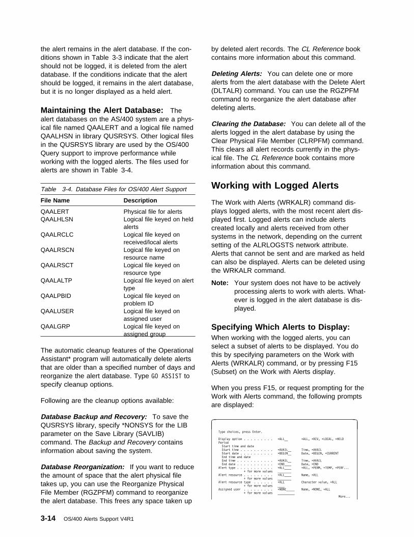
the alert remains in the alert database. If the con-ditions shown in Table 3-3 indicate that the alertshould not be logged, it is deleted from the alertdatabase. If the conditions indicate that the alertshould be logged, it remains in the alert database,but it is no longer displayed as a held alert.
Maintaining the Alert Database: Thealert databases on the AS/400 system are a phys-ical file named QAALERT and a logical file namedQAALHSN in library QUSRSYS. Other logical filesin the QUSRSYS library are used by the OS/400Query support to improve performance whileworking with the logged alerts. The files used foralerts are shown in Table 3-4.
The automatic cleanup features of the OperationalAssistant* program will automatically delete alertsthat are older than a specified number of days andreorganize the alert database. Type GO ASSIST tospecify cleanup options.
Following are the cleanup options available:
Database Backup and Recovery: To save theQUSRSYS library, specify *NONSYS for the LIBparameter on the Save Library (SAVLIB)command. The Backup and Recovery containsinformation about saving the system.
Database Reorganization: If you want to reducethe amount of space that the alert physical filetakes up, you can use the Reorganize PhysicalFile Member (RGZPFM) command to reorganizethe alert database. This frees any space taken up
by deleted alert records. The CL Reference bookcontains more information about this command.
Deleting Alerts: You can delete one or morealerts from the alert database with the Delete Alert(DLTALR) command. You can use the RGZPFMcommand to reorganize the alert database afterdeleting alerts.
Clearing the Database: You can delete all of thealerts logged in the alert database by using theClear Physical File Member (CLRPFM) command.This clears all alert records currently in the phys-ical file. The CL Reference book contains moreinformation about this command.
Working with Logged Alerts
The Work with Alerts (WRKALR) command dis-plays logged alerts, with the most recent alert dis-played first. Logged alerts can include alertscreated locally and alerts received from othersystems in the network, depending on the currentsetting of the ALRLOGSTS network attribute.Alerts that cannot be sent and are marked as heldcan also be displayed. Alerts can be deleted usingthe WRKALR command.
Note: Your system does not have to be activelyprocessing alerts to work with alerts. What-ever is logged in the alert database is dis-played.
Specifying Which Alerts to Display:When working with the logged alerts, you canselect a subset of alerts to be displayed. You dothis by specifying parameters on the Work withAlerts (WRKALR) command, or by pressing F15(Subset) on the Work with Alerts display.
When you press F15, or request prompting for theWork with Alerts command, the following promptsare displayed:
à ð Type choices, press Enter.
Display option . . . . . . . . . \ALL__ \ALL, \RCV, \LOCAL, \HELD
Period
Start time and date
Start time . . . . . . . . . . \AVAIL__ Time, \AVAIL
Start date . . . . . . . . . . \BEGIN__ Date, \BEGIN, \CURRENT
End time and date
End time . . . . . . . . . . . \AVAIL__ Time, \AVAIL
End date . . . . . . . . . . . \END____ Date, \END
Alert type . . . . . . . . . . . \ALL____ \ALL, \PERM, \TEMP, \PERF...
+ for more values ________
Alert resource . . . . . . . . . \ALL____ Name, \ALL
+ for more values ________
Alert resource type . . . . . . \ALL Character value, \ALL
+ for more values ____
Assigned user . . . . . . . . . \NONE_____ Name, \NONE, \ALL
+ for more values __________
More...
Table 3-4. Database Files for OS/400 Alert Support
File Name Description
QAALERT Physical file for alertsQAALHLSN Logical file keyed on held
alertsQAALRCLC Logical file keyed on
received/local alertsQAALRSCN Logical file keyed on
resource nameQAALRSCT Logical file keyed on
resource typeQAALALTP Logical file keyed on alert
typeQAALPBID Logical file keyed on
problem IDQAALUSER Logical file keyed on
assigned userQAALGRP Logical file keyed on
assigned group
3-14 OS/400 Alerts Support V4R1
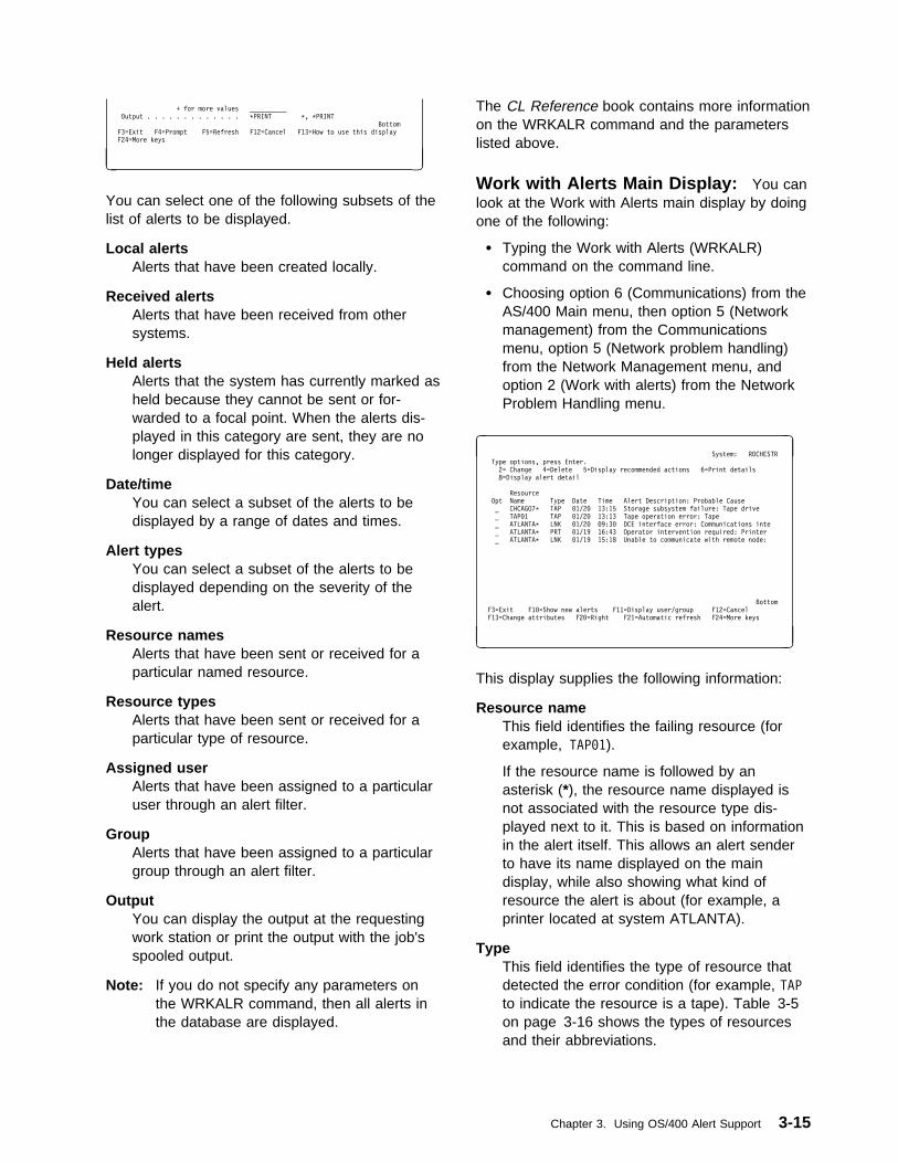
+ for more values __________
Output . . . . . . . . . . . . . \PRINT \, \PRINT
Bottom
F3=Exit F4=Prompt F5=Refresh F12=Cancel F13=How to use this display
F24=More keys
á
ñ
You can select one of the following subsets of thelist of alerts to be displayed.
Local alertsAlerts that have been created locally.
Received alertsAlerts that have been received from othersystems.
Held alertsAlerts that the system has currently marked asheld because they cannot be sent or for-warded to a focal point. When the alerts dis-played in this category are sent, they are nolonger displayed for this category.
Date/timeYou can select a subset of the alerts to bedisplayed by a range of dates and times.
Alert typesYou can select a subset of the alerts to bedisplayed depending on the severity of thealert.
Resource namesAlerts that have been sent or received for aparticular named resource.
Resource typesAlerts that have been sent or received for aparticular type of resource.
Assigned userAlerts that have been assigned to a particularuser through an alert filter.
GroupAlerts that have been assigned to a particulargroup through an alert filter.
OutputYou can display the output at the requestingwork station or print the output with the job'sspooled output.
Note: If you do not specify any parameters onthe WRKALR command, then all alerts inthe database are displayed.
The CL Reference book contains more informationon the WRKALR command and the parameterslisted above.
Work with Alerts Main Display: You canlook at the Work with Alerts main display by doingone of the following:
� Typing the Work with Alerts (WRKALR)command on the command line.
� Choosing option 6 (Communications) from theAS/400 Main menu, then option 5 (Networkmanagement) from the Communicationsmenu, option 5 (Network problem handling)from the Network Management menu, andoption 2 (Work with alerts) from the NetworkProblem Handling menu.
à ð System: ROCHESTR
Type options, press Enter.
2= Change 4=Delete 5=Display recommended actions 6=Print details
8=Display alert detail
Resource
Opt Name Type Date Time Alert Description: Probable Cause
_ CHCAGO7\ TAP ð1/2ð 13:15 Storage subsystem failure: Tape drive
_ TAPð1 TAP ð1/2ð 13:13 Tape operation error: Tape
_ ATLANTA\ LNK ð1/2ð ð9:3ð DCE interface error: Communications inte
_ ATLANTA\ PRT ð1/19 16:43 Operator intervention required: Printer
_ ATLANTA\ LNK ð1/19 15:18 Unable to communicate with remote node:
Bottom
F3=Exit F1ð=Show new alerts F11=Display user/group F12=Cancel
F13=Change attributes F2ð=Right F21=Automatic refresh F24=More keys
á
ñ
This display supplies the following information:
Resource nameThis field identifies the failing resource (forexample, TAPð1).
If the resource name is followed by anasterisk (*), the resource name displayed isnot associated with the resource type dis-played next to it. This is based on informationin the alert itself. This allows an alert senderto have its name displayed on the maindisplay, while also showing what kind ofresource the alert is about (for example, aprinter located at system ATLANTA).
TypeThis field identifies the type of resource thatdetected the error condition (for example, TAPto indicate the resource is a tape). Table 3-5on page 3-16 shows the types of resourcesand their abbreviations.
Chapter 3. Using OS/400 Alert Support 3-15
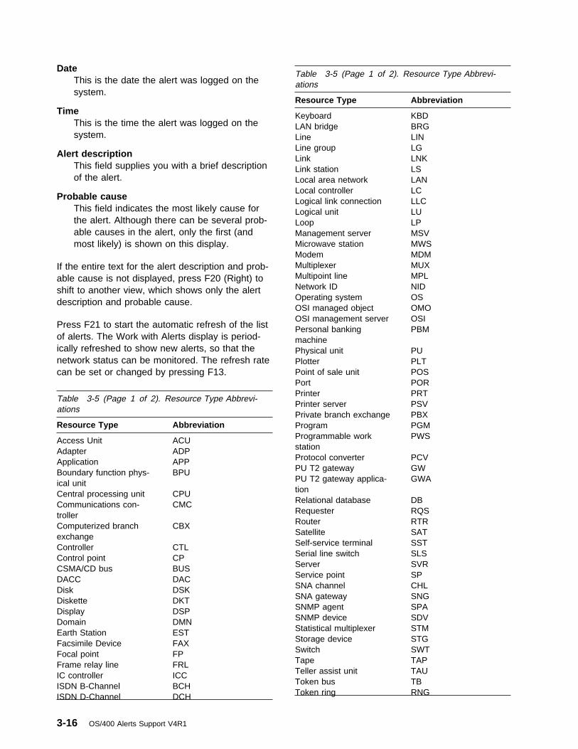
DateThis is the date the alert was logged on thesystem.
TimeThis is the time the alert was logged on thesystem.
Alert descriptionThis field supplies you with a brief descriptionof the alert.
Probable causeThis field indicates the most likely cause forthe alert. Although there can be several prob-able causes in the alert, only the first (andmost likely) is shown on this display.
If the entire text for the alert description and prob-able cause is not displayed, press F20 (Right) toshift to another view, which shows only the alertdescription and probable cause.
Press F21 to start the automatic refresh of the listof alerts. The Work with Alerts display is period-ically refreshed to show new alerts, so that thenetwork status can be monitored. The refresh ratecan be set or changed by pressing F13.
Table 3-5 (Page 1 of 2). Resource Type Abbrevi-ations
Resource Type Abbreviation
Keyboard KBDLAN bridge BRGLine LINLine group LGLink LNKLink station LSLocal area network LANLocal controller LCLogical link connection LLCLogical unit LULoop LPManagement server MSVMicrowave station MWSModem MDMMultiplexer MUXMultipoint line MPLNetwork ID NIDOperating system OSOSI managed object OMOOSI management server OSIPersonal bankingmachine
PBM
Physical unit PUPlotter PLTPoint of sale unit POSPort PORPrinter PRT
Table 3-5 (Page 1 of 2). Resource Type Abbrevi-ations
Printer server PSVPrivate branch exchange PBX
Resource Type Abbreviation Program PGMProgrammable workstation
PWSAccess Unit ACUAdapter ADP
Protocol converter PCVApplication APPPU T2 gateway GWBoundary function phys-
ical unitBPU
PU T2 gateway applica-tion
GWA
Central processing unit CPURelational database DBCommunications con-
trollerCMC
Requester RQSRouter RTRComputerized branch
exchangeCBX
Satellite SATSelf-service terminal SSTController CTLSerial line switch SLSControl point CPServer SVRCSMA/CD bus BUSService point SPDACC DACSNA channel CHLDisk DSKSNA gateway SNGDiskette DKTSNMP agent SPADisplay DSPSNMP device SDVDomain DMNStatistical multiplexer STMEarth Station ESTStorage device STGFacsimile Device FAXSwitch SWTFocal point FPTape TAPFrame relay line FRLTeller assist unit TAUIC controller ICCToken bus TBISDN B-Channel BCHToken ring RNGISDN D-Channel DCH
3-16 OS/400 Alerts Support V4R1
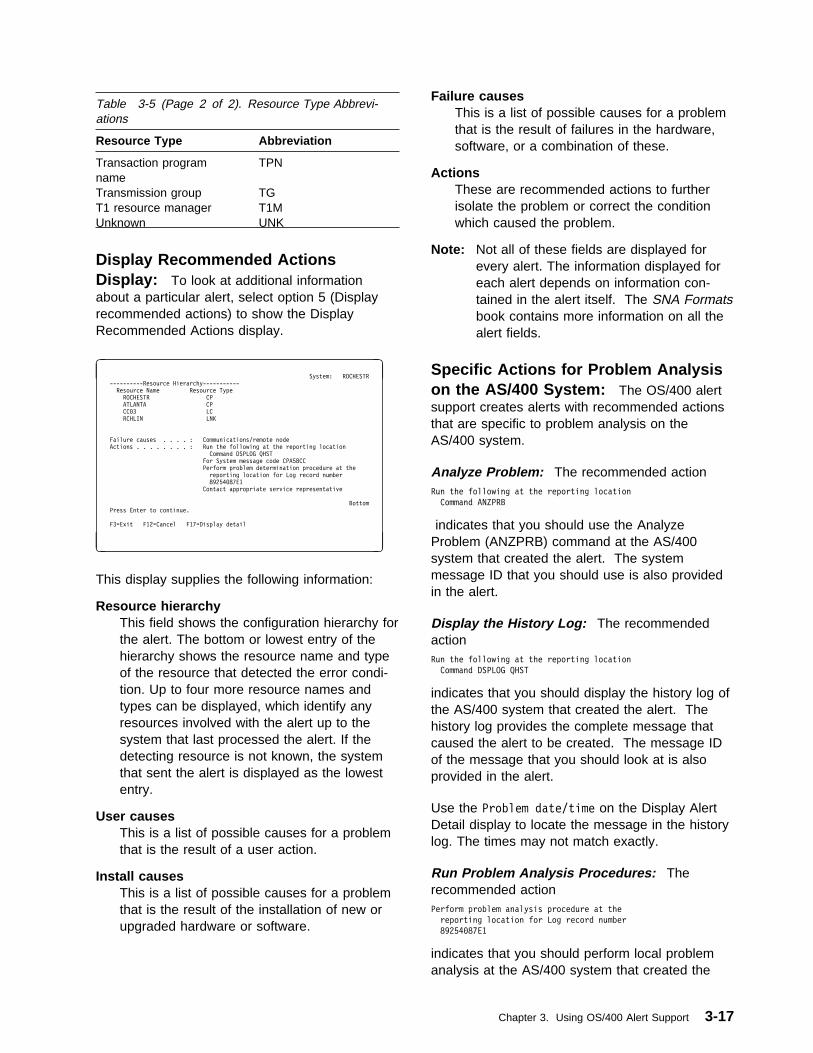
Display Recommended ActionsDisplay: To look at additional informationabout a particular alert, select option 5 (Displayrecommended actions) to show the DisplayRecommended Actions display.
à ð System: ROCHESTR
----------Resource Hierarchy-----------
Resource Name Resource Type
ROCHESTR CP
ATLANTA CP
CCð3 LC
RCHLIN LNK
Failure causes . . . . : Communications/remote node
Actions . . . . . . . . : Run the following at the reporting location
Command DSPLOG QHST
For System message code CPA58CC
Perform problem determination procedure at the
reporting location for Log record number
89254ð87E1
Contact appropriate service representative
Bottom
Press Enter to continue.
F3=Exit F12=Cancel F17=Display detail
á
ñ
This display supplies the following information:
Resource hierarchyThis field shows the configuration hierarchy forthe alert. The bottom or lowest entry of thehierarchy shows the resource name and typeof the resource that detected the error condi-tion. Up to four more resource names andtypes can be displayed, which identify anyresources involved with the alert up to thesystem that last processed the alert. If thedetecting resource is not known, the systemthat sent the alert is displayed as the lowestentry.
User causesThis is a list of possible causes for a problemthat is the result of a user action.
Install causesThis is a list of possible causes for a problemthat is the result of the installation of new orupgraded hardware or software.
Failure causesThis is a list of possible causes for a problemthat is the result of failures in the hardware,software, or a combination of these.
ActionsThese are recommended actions to furtherisolate the problem or correct the conditionwhich caused the problem.
Note: Not all of these fields are displayed forevery alert. The information displayed foreach alert depends on information con-tained in the alert itself. The SNA Formatsbook contains more information on all thealert fields.
Specific Actions for Problem Analysison the AS/400 System: The OS/400 alertsupport creates alerts with recommended actionsthat are specific to problem analysis on theAS/400 system.
Analyze Problem: The recommended actionRun the following at the reporting location
Command ANZPRB
indicates that you should use the AnalyzeProblem (ANZPRB) command at the AS/400system that created the alert. The systemmessage ID that you should use is also providedin the alert.
Display the History Log: The recommendedactionRun the following at the reporting location
Command DSPLOG QHST
indicates that you should display the history log ofthe AS/400 system that created the alert. Thehistory log provides the complete message thatcaused the alert to be created. The message IDof the message that you should look at is alsoprovided in the alert.
Use the Problem date/time on the Display AlertDetail display to locate the message in the historylog. The times may not match exactly.
Run Problem Analysis Procedures: Therecommended actionPerform problem analysis procedure at the
reporting location for Log record number
89254ð87E1
indicates that you should perform local problemanalysis at the AS/400 system that created the
Table 3-5 (Page 2 of 2). Resource Type Abbrevi-ations
Resource Type Abbreviation
Transaction programname
TPN
Transmission group TGT1 resource manager T1MUnknown UNK
Chapter 3. Using OS/400 Alert Support 3-17

alert. The Log record number identifies theproblem ID.
See “Alerts and Local Problem Analysis” onpage 3-4 for information about local problem anal-ysis.
Print Details: Print details (option 6) printsthe details of the selected alert to a spooled file.
Display Alert Detail Display: The DisplayAlert Detail display supplies further details aboutthe selected alert. You can look at this display bypressing F17 (Display detail) from the DisplayRecommended Actions display or typing option 8(Display alert detail) next to the alert on the Workwith Alerts display. This display may consist ofmore than one display of data.
à ð System: ROCHESTR
----------Resource Hierarchy-----------
Resource Name Resource Type
ROCHESTR CP
ATLANTA CP
CCð3 LC
RCHLIN LNK
Logged date/time . . . . . . : ð2/15/88 15:18:ð4
Problem date/time . . . . . : ð2/15/88 15:18:ð1
Assigned user . . . . . . . :
Group assigned . . . . . . . :
Filter . . . . . . . . . . . :
Library . . . . . . . . . :
Alert type . . . . . . . . . : Permanent
Alert description . . . . . : Unable to communicate with remote node
Probable causes . . . . . . : Communications
Communications/remote node
More...
Press Enter to continue.
F3=Exit F11=Display detail menu F12=Cancel F18=Display actions
á
ñ
This display can show the following information:
Logged date/timeThis is the date and time that the alert waslogged. This is the same date and time thatappear on the Work with Alerts display.
Problem date/timeThis is the date and time that the alert wascreated and reflects the time that the alertablecondition was detected.
Assigned userThis is the user assigned to the alert. Theuser is assigned through the alert filter.
Group assignedThis is the group into which the alert is fil-tered.
FilterThis is the filter that was active when this alertwas processed. This field is only shown if auser and group are not changed.
LibraryThis is the library where the active filter is.This field is only shown if a user and groupare not changed.
Alert typeThe alert type defines the severity of theproblem. Possible values are:
PermanentThis is a loss of availability to the userthat requires the focal point operator tointervene.
TemporaryThis is a momentary loss of availabilitythat can affect the user, but does notrequire the focal point operator to inter-vene.
PerformanceThe alerted condition may be causing anunacceptable level of performance.
Impending problemThis is a potential loss of availability to theuser that has not yet happened.
Permanently affected resourceThe originator of this alert has determinedthat the target resource is lost because ofa persistent error in a resource other thanthe target.
UnknownThe severity of the alert condition cannotbe determined.
Alert descriptionThe alert description defines the condition thatcaused the alert.
Probable causesLists the causes that, in the alert sender'sview, are the most probable causes for thealert condition. These causes are listed inorder of decreasing probability.
Notice that there is a difference between theprobable cause, and the user, install, or failurecauses listed on the Display RecommendedActions display. The probable causes specify
3-18 OS/400 Alerts Support V4R1

what it is that has failed, while the othersspecify what is wrong with a probable cause.
For example, a probable cause may indicate acable, while the user cause for the same alertmight indicate that this cable is unplugged.
à ð System: ROCHESTR
----------Resource Hierarchy-----------
Resource Name Resource Type
ROCHESTR CP
ATLANTA CP
CCð3 LC
RCHLIN LNK
Qualifiers . . . . . . . . . : AS/4ðð Message code CPA58CC
AS/4ðð Message severity 99
Text message:
Sender ID . . . . . . . . : Control program
Message . . . . . . . . . : Line RCHLIN failed. Recovery stopped.(C G R)
Reason code: X'54ðð2ð5ð'
More...
Press Enter to continue.
F3=Exit F11=Display detail menu F12=Cancel F18=Display actions
á
ñ
QualifiersLists product-specific detailed data about thealert condition.
Detailed data qualifiers can appear in severaldifferent places on the alerts displays:
� As part of a user, install, or failure causeon the Display Recommended Actionsdisplay.
� As part of an action on the DisplayRecommended Actions display.
� In the Qualifiers section of the DisplayAlert Detail display.
A detailed data qualifier is made up of threeparts:
Product identificationIdentifies the product associated with thisdetailed data qualifier. This part does nothave to be present.
Data identificationIdentifies the type of detailed data presentin this qualifier.
Detailed dataThe detailed data itself, in either char-acter, hexadecimal, or decimal form.
Following is an example of a detailed dataqualifier with two of the above three parts:
Command DSPLOG QHST
where Command is the data identification, andDSPLOG QHST is the detailed data.
Following is an example of a detailed dataqualifier with all of the parts:
AS/4ðð Message code CPA58CC
where AS/4ðð is the product identification,Message code is the data identification, andCPA58CC is the detailed data.
Text messageProvides a text message from the alert senderabout the problem. For alerts from an AS/400system, the text message is the first level textfor the message that caused the alert to besent.
This section is made up of one or more of thefollowing fields. The exact fields presentdepend on what is present in the alert. Thepossible fields are:
Sender ID Identifies the alert sender. The fol-lowing values are possible:
Display station user A personwho is only a user ofsystem resources (notan operator).
Operator A person who isresponsible for man-aging system resources.
Application program A programwritten by or for a user.
Control program A program thatcontrols the systemresources.
Message The actual message text. Noticethat this text is displayed in the lan-guage in which the message wascreated at the alert sender.
You can press F11 to use the Display DetailMenu display. This display allows you toselect the functions shown.
Chapter 3. Using OS/400 Alert Support 3-19

à ð System: ROCHESTR
----------Resource Hierarchy-----------
Resource Name Resource Type
ROCHESTR CP
ATLANTA CP
CCð3 LC
RCHLIN LNK
Select one of the following:
1. Display flags
2. Display product identification
5. Display LAN data
6. Display alert in hexadecimal
Selection or command
===> ____________________________________________________________
F3=Exit F4=Prompt F9=Retrieve F12=Cancel
á
ñ
à ð System: ROCHESTR
----------Resource Hierarchy-----------
Resource Name Resource Type
ROCHESTR CP
ATLANTA CP
CCð3 LC
RCHLIN LNK
Flags:
Local/Received . . . . . . : Received
Operator generated . . . . : No
Held alert . . . . . . . . : No
Delayed alert . . . . . . : No
Analysis available . . . . : Yes
More...
Press Enter to continue.
F3=Exit F12=Cancel
á
ñ
FlagsLists flags associated with the alert. The flagsdisplayed are:
Local/Received Specifies whether the alertwas created locally or receivedfrom another system.
Operator generated Specifies if this alert wasgenerated by a network operator.
Held alert Specifies if this alert has at anytime been held at the sendingsystem or an intermediate systembecause of problems with sendingthe alert.
Delayed alert Specifies if this is a delayedalert. A delayed alert reports theerror condition that resulted in anyheld alerts.
Analysis available The analysis indicator isset to Yes if you can run problemanalysis procedures on theproblem.
à ð System: ROCHESTR
----------Resource Hierarchy-----------
Resource Name Resource Type
ROCHESTR CP
ATLANTA CP
CCð3 LC
RCHLIN LNK
Sender hardware identification:
Product classification . . : IBM hardware
Machine type . . . . . . . : 94ð6
Model number . . . . . . . : A4ð
Plant of manufacture . . . : 1ð
Sequence number . . . . . : ð1234
Common name . . . . . . . : AS/4ðð
More...
Press Enter to continue.
F3=Exit F12=Cancel
á
ñ
Sender hardware identificationProvides information to identify the hardwareproduct for the alert sender.
This section is made up of one or more of thefollowing fields. The exact fields presentdepend on what is present in the alert. Thepossible fields are:
Product classification What type of productthis is:
� IBM hardware
� IBM or non-IBM hardware (notdistinguished)
� Non-IBM hardware
Machine type A 4-digit descriptor of themachine type.
Model number The model number of themachine.
Plant of manufacture The IBM plant of man-ufacture.
Sequence number The sequence number ofthe machine originating the errorrecord.
Common name The hardware common nameas given in the product announce-ment.
Microcode EC level Engineering Change(EC) level of the failing microcodecomponent.
Emulated machine type Type of the hard-ware product being emulated, ifemulation is being done.
Emulated model number The model numberof the product being emulated, ifemulation is being done.
3-20 OS/400 Alerts Support V4R1

Resource hardware identificationProvides information to identify the hardwareproduct for the failing resource.
This section has the same fields possible asthe Sender hardware identification section.
à ð System: ROCHESTR
----------Resource Hierarchy-----------
Resource Name Resource Type
ROCHESTR CP
ATLANTA CP
CCð3 LC
RCHLIN LNK
Sender software identification:
Product classification . . : IBM software
Program product number . . : 5716SS1
Version . . . . . . . . . : ð2
Release . . . . . . . . . : ð1
Level . . . . . . . . . . : ðð
Common name . . . . . . . : OS/4ðð
Bottom
Press Enter to continue.
F3=Exit F12=Cancel
á
ñ
Sender software identificationProvides information to identify the softwareproduct for the alert sender.
This section is made up of one or more of thefollowing fields. The exact fields presentdepend on what is present in the alert. Thepossible fields are:
Product classification Identifies what type ofproduct this is.
� IBM software
� IBM or non-IBM software (notdistinguished)
� Non-IBM software
Program product number The productnumber of the program.
Serviceable component ID Component iden-tification of a serviceable compo-nent, as assigned by servicepersonnel.
Serviceable component level The releaselevel as assigned by service per-sonnel.
Version The version of the program.
Release The release level of the program.
Level The level of the program.
Common name Common name of software.
Customization date Date when a set ofinstructions was customized to auser's environment.
Customization time Time when a set ofinstructions was customized to auser's environment.
Customization identifier Identification of aset of instructions, customized to auser's environment.
Resource software identificationProvides information to identify the softwareproduct for the failing resource.
This section has the same fields possible asthe Sender software identification section.
à ð System: ROCHESTR
----------Resource Hierarchy-----------
Resource Name Resource Type
ROCHESTR CP
ATLANTA CP
CCð3 LC
RCHLIN LNK
LAN data
Ring or bus ID . . . . . . : ððð1
Fault domain description . : 4ððð141ððððð 4ððððððð21ð1
Bottom
Press Enter to continue.
F3=Exit F12=Cancel
á
ñ
LAN dataProvides information related to local areanetwork (LAN) errors.
This section is made up of one or more of thefollowing fields. The exact fields presentdepend on what is present in the alert. Thepossible fields are:
LAN identifier Identifies a local area network(LAN).
Ring or bus ID Identifies the ring number fora token-ring local area network orthe bus number for an Ethernetnetwork. This is displayed inhexadecimal format.
Local individual MAC address Identifies theaddress of the medium accesscontrol (MAC) within the nodesending the alert. This is displayedin hexadecimal format.
Remote individual MAC address Identifiesthe address of the medium accesscontrol (MAC), which is part of thelink connection, within the adjacentnode. This is displayed inhexadecimal format.
Chapter 3. Using OS/400 Alert Support 3-21

LAN routing information Identifies therouting information used by a link.
Fault domain description Identifies thelocation on the network where anerror is likely to be occurring, typi-cally bounded by the address oftwo stations; for example, theupstream and the downstreamlocal area network stations and thecable between them. This fieldcontains:
� Individual medium accesscontrol (MAC) address ofdownstream station inhexadecimal format.
� Individual medium accesscontrol (MAC) address ofupstream station inhexadecimal format.
Beaconing data Message or data sent by astation that detects a problem.
Single MAC address Specifies the address ofthe medium access control (MAC)element associated with the failure.
Fault domain error weight pair Indicates theseverity of the problems reportedby two medium access control(MAC) elements (the reportingstation or the nearest activeupstream neighbor).
Bridge identifier Identifies the bridge identi-fier of a local area network (LAN)bridge. The bridge identifier is com-posed of the following:
� Ring or bus number
� Bridge number
� Another ring or bus number
This is displayed in hexadecimalformat.
Local individual MAC name Identifies thename of the medium accesscontrol (MAC) element within thesending node.
Remote individual MAC name Identifies thename of the medium accesscontrol (MAC) element, which is
part of the link connection, withinthe adjacent node.
Fault domain names Identifies the names ofthe upstream and the downstreamlocal area network (LAN) stationsthat define the location on thenetwork where the error is likely tobe occurring.
Single MAC name Identifies the name of themedium access control (MAC)element related to the failure.
MAC Type Identifies the type of media accesscontrol (MAC) sub-layer to whichthe sender is attached. FDDI,Ethernet, and token bus are pos-sible media access control (MAC)sub-layer types.
FDDI Station ID Contains a unique identifierfor the fiber distributed data inter-face (FDDI) station transmitting theframe data.
Frame Counter The hexadecimal count of allframes received by this mediaaccess control (MAC).
Error Counter The hexadecimal count ofcomplete frames received in errorby this media access control(MAC) and no previous station.
Lost Counter The hexadecimal count offrames and tokens detected with aformat error by this Media AccessControl (MAC) and no previousMAC.
Not Copied Counter The hexadecimal countof all frames addressed to thismedia access control (MAC) thatwere not copied, but should havebeen. One possible cause could belocal buffer congestion.
Copied Counter The hexadecimal count of allframes that were successfullyreceived into the station's buffersby a media access control (MAC)sub-layer.
Local Station Condition This field indicateswhether or not a duplicate addressoccurs at this station. Upstreamneighbor condition - Help
3-22 OS/400 Alerts Support V4R1

Upstream Neighbor Condition This field indi-cates whether or not a duplicateaddress occurs at the upstreamneighbor.
Upstream Neighbor Address DuplicateAddress The Media AccessControl (MAC) address of theupstream neighbor with a duplicateaddress.
Link Error Rate Cutoff When the link errorrate is less than or equal to thisvalue, a connection is flagged asfaulty. Link error rate is the expo-nent (in hexadecimal) of the totalbits per error bit.
Link Error Rate Alarm When the link errorrate is less than or equal to thisvalue, an alarm condition occurs.Link error rate is the exponent (inhexadecimal) of the total bits pererror bit.
Link Error Rate Estimate An average, long-term link error rate. Link error rateis the exponent (in hexadecimal) ofthe total bits per error bit.
Link Error Monitor Reject Counter Thishexadecimal number counts thenumber of times a link has beenremoved because it exceeded thelink cutoff threshold.
Link Error Monitor Counter A hexadecimalnumber counting all link errormonitor (LEM) errors. This value iszeroed only during station initializa-tion.
Configuration State The configuration stateafter a configuration change hasoccurred at a station orconcentrator.
Paths Available The paths available after aconfiguration change has occurred.The possible values are primary,secondary, and local.
Port Connector Type The type of port con-nector from which an undesiredconnection has been attempted.
Connect State Indicates the connection stateof the port on this station with anundesired connection.
Port Connector Neighbor Indicates the otherport in the undesired connection,which resides in the neighborstation.
Connection Accepted Indicates whether ornot the undesired connectionattempt was accepted.
FDDI Trace Status Contains the current tracestatus of the path. FDDI ElasticityBuffer Error Counter - Help
FDDI Elasticity Buffer Error Counter Ahexadecimal count of the numberof times an elasticity buffer errorhas occurred.
FDDI Hold State Indicates whether theprimary or secondary rings areoperational and the recoveryenable flag is clear.
FDDI MAC Index Contains the hexadecimalidentifier for a particular mediaaccess control (MAC) sub-layerwithin a station.
FDDI Port Index A hexadecimal identifier ofthe communication port for thestation
FDDI Path Index A hexadecimal identifier ofthe communication path for thestation
FDDI Station Name Contains the name of theoriginating station.
Address Format This identifies the format orbit ordering of the media accesscontrol (MAC) addresses in thissubvector. The possible values arecanonical format and most signif-icant bit first.
FDDI Peer Wrap Data A dual-attachmentmode creates this field while it iswrapped and in peer-connectionmode.
FDDI Neighbor Change Data These valuesare created when the FDDIneighbor notification protocoldetects a change in either anupstream or a downstream mediaaccess control (MAC).
Chapter 3. Using OS/400 Alert Support 3-23
FDDI MAC Path Change Data These valuesare created when the current pathvalue changes for any mediaaccess control (MAC). The changecould occur from primary to sec-ondary or from secondary toprimary.
FDDI Port Path Change Data These valuesare created when the current pathvalue changes for any port in astation. The change could occurfrom primary to secondary or fromsecondary to primary.
Note: Not all of these fields are displayed forevery alert. The information displayed foreach alert depends on information con-tained in the alert itself. The SNA Formatsbook contains more information on all thealert fields.
SNA Generic Alerts
The AS/400 system supports the SNA genericalert architecture. The text that makes up an alertis represented by code points . A code point is a1-byte (2 hexadecimal characters) or 2-byte (4hexadecimal characters) code that designates aparticular piece of text to be displayed at the focalpoint. Code points are sent by an alert sender toconvey alert data and are used to get the units oftext for displaying alert data at a focal point.
An example of a code point is probable causeX'6314'. The text for this code point is Tapedrive. The code point X'6314' is sent in the alert.The text Tape drive is displayed by the AS/400system on the alerts displays.
Generic Alert Code Points: Generic alertcode points are used in the following fields of thealert display:
� Alert type . The alert type code point definesthe severity of the problem.
� Alert description . The alert description codepoint describes the alert condition.
� Probable causes . These codes define themost likely causes of the condition beingdescribed.
� User causes . These codes describe the con-ditions caused by a user and defined as con-ditions that can be resolved by the operatorwithout contacting any service organization.
� Install causes . These codes describe condi-tions resulting from the initial installation orset-up of equipment.
� Failure causes . These codes describe condi-tions caused by the failure of a resource.
� Recommended actions . These codesdescribe actions that the focal point operatorcan take to correct the problem that causedthe alert or to complete the process ofproblem analysis.
� Qualifiers . Detail qualifiers can appear inuser, install, or failure causes, and in therecommended actions. They can also appearalone in the Qualifiers section of the DisplayAlert Detail display. The code point used fordetail qualifiers is a data ID that identifies thedetail qualifier.
� Resource type . These codes describe thetype of resources that detected the error con-dition.
The AS/400 system uses the generic alert archi-tecture. The code points are converted to amessage ID, which is used to retrieve the text thatis to be displayed on the alert displays from thealert message file. The name of the OS/400 alertmessage file is QALRMSG in library QSYS.
Default Code Points: A code point is of theform xxxx, where x is any hexadecimal digit (a1-byte code point is of the form xx).
A default code point is a code point of the formxx00. Default code points are special because ifthe AS/400 system cannot find a code point xxxxin the QALRMSG alert message file, the AS/400system also tries the default code point xx00. Adefault code point is less specific than the originalcode point, but still provides useful information.For example, the text for probable cause codepoint X'6314' is Tape drive. Probable causecode point X'6300' is Input/output device.
3-24 OS/400 Alerts Support V4R1

Adding Code Points to the OS/400Alert Message File: If the AS/400 systemcannot find a code point or its default in theQALRMSG alert message file, the text\UNKNOWN(xxxx) is displayed where the code pointtext would have been displayed. xxxx is theunknown code point.
The following conditions can result in an*UNKNOWN code point:
� A code point that is not contained in the latestrelease level of the OS/400 alert message file.
� User application code point. Code pointsX'E000' to X'EFFF' are reserved for use bynon-IBM products and customer applications.
� The sending system is in error.
A default code point may be displayed instead ofthe more specific one.
To add a code point to your AS/400 system, youmust create a message in the alert message file.
To create a code point message, you need toknow the code point (either the 2-digit or 4-digitvalue), the code point type, and the message text.More information is contained in the SNA Formatsbook.
Determining the Message ID: The message IDfor a code point consists of the code point plus a3-character prefix. Table 3-6 shows the messageID prefixes for the alert code points:
For example, the message ID for failure causeX'1234' is ALF1234.
The code point for the detail qualifier data ID isonly 2 hexadecimal digits. It is represented as amessage ID by ALXccðð where cc is the 1-byte (2hexadecimal characters) code point. For example,
the message ID for detail data ID X'12' isALX12ðð.
The code point for the resource type consists ofonly 2 hexadecimal digits. It is represented as amessage ID by ALZccðð where cc is the 1-byte (2hexadecimal character) code point. For example,the message ID for resource type X'25' isALZ25ðð.
The code point for alert type consists of only 2hexadecimal digits. It is represented as amessage ID by ALTccðð where cc is the 1-byte (2hexadecimal character) code point. For example,the message ID for alert type X'03' is ALTð3ðð.
Code Point Text Length Restrictions: Thelength restrictions for the alert code point mes-sages are as follows:
� Alert description, probable cause: 90 charac-ters
� User/install/failure causes, recommendedactions: 132 characters
� Resource type: 2 or 3 character abbreviation(for example, TAP DKT)
If you create a code point message that is longerthan the length specified, the last part of the codepoint message text is not shown on the alert dis-plays.
Detailed Qualifiers: Some of the generic alertcode points contain detailed qualifiers. A detailedqualifier is one of the following:
� Detailed data qualifier
� Product identifier qualifier
These detailed qualifiers are sent in the alert withthe code point, and are put together by theAS/400 system on the alert displays. The followingcode point types can contain detailed qualifiers:
� User causes
� Install causes
� Failure causes
� Recommended actions
Each code point can contain from 0 to 3 detaileddata qualifiers (for example, Command DSPLOG
QHST), or a code point can contain a product iden-tifier qualifier (for example, AS/4ðð).
Table 3-6. Converting a Code Point to a Message ID
3-Character Prefix Code Point
ALD Alert descriptionALP Probable causeALU User causeALI Install causeALF Failure causeALR Recommended actionALT Alert typeALX Detail data IDALZ Resource type
Chapter 3. Using OS/400 Alert Support 3-25

The number of detailed data qualifiers a codepoint contains is determined by the code pointitself. The third hexadecimal digit of the codepoint determines the number of qualifiers presentin the code point. For code point X'xxYx', Ydetermines the number. Table 3-7 lists thenumber of qualifiers required by a code point withthe given third digit.
Substitution Text for Detailed Qualifiers:When you create a code point message that con-tains detailed qualifiers, you must specify wherethe qualifiers will be displayed. The SNA Formatsbook defines where in the code point text thequalifiers appear; you can control if they appearon the same line as all the remaining code pointtext, or on the line or lines following the code pointtext.
To specify detailed qualifiers that appear on thesame line as the code point text, you use substi-tution variables to define the placement of thequalifiers. Table 3-8 shows the substitution vari-able numbers that should be used for each qual-ifier.
If the detailed qualifier placement is defined at theend of the code point text, you can omit the sub-stitution variable at the end of the text, and the
system displays the detailed qualifier on the linefollowing the code point text.
Note: Detailed qualifiers that are defined in themiddle of the code point text must have asubstitution variable.
Example 1
For example, recommended action X'F0A0' (onedetailed data qualifier) is defined as follows:
For &1;
It might appear on the alert displays as:For System message code CPA58CC
Example 2
Recommended action X'00B2' (one detailed dataqualifier) is defined as follows:Run the following at the reporting location
It might appear on the alert displays as:Run the following at the reporting location
Command DSPLOG QHST
Example 3
Recommended action X'00E1' requires oneproduct identifier qualifier, and is defined as:
Perform &4; problem analysis.
It might appear on the alert displays as:
Perform AS/4ðð problem analysis.
Creating a Message Description: To add codepoint text, use the code point to create a messageID and add a message description to the alertmessage file. For example, to add probable causeX'6314', Tape device, the message ID isALP6314.
The name of the OS/400 alert message file isQALRMSG in library QSYS. Use the AddMessage Description (ADDMSGD) command toadd the code point message.ADDMSGD MSGF(QSYS/QALRMSG) MSGID(ALP6314)
MSG('Tape device')
The following command adds the code pointmessage for Example 1 on page 3-26.ADDMSGD MSGF(QSYS/QALRMSG) MSGID(ALRFðAð)
MSG('For &1')
FMT((\CHAR \VARY 2) (\CHAR ð) (\CHAR ð) (\CHAR ð))
The following command adds the code pointmessage for Example 2 on page 3-26.
Table 3-7. Number of Detailed Qualifiers for a CodePoint
Third Digit Number of Qualifiers
X'xx0x' - X'xx9x' No detailed qualifiersX'xxAx' - X'xxBx' One detailed data qual-
ifierX'xxCx' Two detailed data qual-
ifiersX'xxDx' Three detailed data qual-
ifiersX'xxEx' One product identifier
qualifier
Table 3-8. Substitution Variables Used for DetailedQualifiers
Variable Description
1 First detailed data qual-ifier
2 Second detailed dataqualifier
3 Third detailed data qual-ifier
4 Product identifier qualifier
3-26 OS/400 Alerts Support V4R1

ADDMSGD MSGF(QSYS/QALRMSG) MSGID(ALRððB2)
MSG('Run the following at the reporting location')
Since the detail qualifier text is placed on the nextline, no substitution variables are defined.
The following command adds the code pointmessage for Example 3 on page 3-26.
ADDMSGD MSGF(QSYS/QALRMSG) MSGID(ALRððB2)
MSG('Perform &4; problem analysis.')
FMT((\CHAR ð) (\CHAR ð) (\CHAR ð) (\CHAR \VARY 2))
Displaying the Contents of the Alert MessageFile: To display the code points that are currentlyin the alert message file, use the Work withMessage Description (WRKMSGD) command:
WRKMSGD MSGF(QSYS/QALRMSG)
Chapter 3. Using OS/400 Alert Support 3-27

3-28 OS/400 Alerts Support V4R1

Chapter 4. OS/400 Alert Filter Support
This chapter describes the OS/400 alert filtersupport on the AS/400 system. It describes howalert filters can be used to route and processSystems Network Architecture (SNA) alerts in anetwork and how to automate operations for localalerts or received alerts within a network.
Filter Components
Selection entry and action entry are the two com-ponents that comprises a filter. They can eitherwork together or be used individually by a systemsmanagement application. Figure 4-1 on page 4-2
illustrates the components of a filter.
A network administrator decides how the filtershould process the alerts. For example, thenetwork administrator might want all diskette, tape,and display alerts to be handled by Joe Miller. Thenetwork administrator creates an alert filterobject , which consists of the selection and actionentries. In this example, the administrator createsa selection entry that assigns all diskette, tape,and display alerts to the group HARDWJOE.Then, the administrator creates an action entry forthe group HARDWJOE that logs the alerts andassigns them to user JMILLER.
Selection Entries
Selection entries assign each alert processed by afilter to a group. Each selection entry includes alogical expression that relates the alert attributesto values. Within these logical expressions, *ANDhas precedence over *OR or *IF. Selection entriesare evaluated in the order in which they aresequenced. The first true expression determinesthe group to which each alert is assigned.
The attributes describe what to look for in thealert, for example, *RSCNAME and *ALERTID.The value specifies what the attribute should be toprovide a match for that particular alert, forexample, “CHICAGO” and “01235FB4.” In thisexample, if the alert has an *RSCNAME valueequal to CHICAGO and an *ALERTID equal to01235FB4, the alert is assigned to the groupTEMPORARY.
Once an alert has satisfied a selection entry, it isassigned to a group. The group is also a char-acter value defined by the network administrator.The selection entry allows the administrator togroup classes of alerts.
For example, an administrator may want all alertsthat are for diskettes, tapes, or displays to beassigned to the HARDWJOE group. TheHARDWJOE group in the administrator's alert filterpolicy means hardware problems for which Joe isresponsible. In addition, the administrator wants allalerts that are for temporary or impending prob-lems assigned to the group BITBUCKET. TheBITBUCKET group in the administrator's alert filterpolicy is for alerts that should not be logged.
Action Entries
Action entries specify what should be done toprocess each group of alerts. The actions aredefined by the network administrator as part of thefilter object. Part of the policy defines how thegroups specified by the selection entries should bemapped to the actions that can be taken. Possibleactions include:
� Logging the alert. Alerts can be used fortracking purposes.
� Routing the alert to an assigned user. Alertscan be assigned to a specific user. Operatorscan then display alerts assigned to them. Thisallows operators to work with alerts that havebeen specifically routed to them.
� Routing notification of the alert to a dataqueue. This enables a systems managementapplication to monitor the data queue and takeaction when alerts are received. For example,an application can automate the responses toseveral groups of alerts.
� Routing the alert to another system in thenetwork. By routing the alerts from an unat-tended to an attended system in the network,you can ensure that the alerts for the unat-tended system are processed.
In the previous example, the actions for groupHARDWJOE may be to log the alert and then
Copyright IBM Corp. 1997 4-1

assign the alert to the user JOE. The groupBITBUCKET is not logged, so there are no otheractions to perform. The alert is discarded.
Working with Alert Filters
Before you can begin working with alert filters, youneed to establish your alert filter policy. Once youhave established your policy, you can create thefilters and their components. Filters and their com-ponents are created and maintained through aseries of commands and displays. “Working withAlert Selection Entries” on page 4-3 and “Workingwith Alert Action Entries” on page 4-4 describehow to work with alert filter components.
Use the ALRFTR parameter of the ChangeNetwork Attribute (CHGNETA) command tospecify the active alert filter.
Figure 4-2 on page 4-3 shows how an adminis-trator works with the filter components.
Use the Work with Filters (WRKFTR) command toaccess all the filter functions available. TheWRKFTR command allows you to work with a listof filters, change and delete filters, work withselection entries and action entries that are con-tained in filters, create new filters, and print thecontents (selection and action entries) of thefilters.
Note: Only the libraries for which you haveREAD authority are searched.
Only the filters for which you have some authorityare shown on the display.
To perform operations on the filters, you musthave USE authority to the command used by theoperation and the appropriate authority to thefilters on which the operation is to be performed.
When you enter the WRKFTR command, adisplay similar to the following is shown:
à ð System: RCHAS2ð9
Type options, press Enter.
1=Create 2=Change 4=Delete 5=Work with filter selection entries
6=Print 8=Work with filter action entries
Opt Filter Library Type Text
_ __________ __________
_ ALRBACKUP BACKUP \ALR Backup filter for Alerts
_ ORIGINAL BACKUP \ALR Original Alert filter
_ ALERTFTR NETMGMT \ALR Filter for Alert processing
_ TIMOTHY TGFLIB \ALR Alert filter for TGF
To create a filter, select option 1 (Create) from theWork with Filters display. A Create Filter(CRTFTR) display similar to the following appears.
à ð Type choices, press Enter.
Filter . . . . . . . . . . . . . __________ Name
Library . . . . . . . . . . . \CURLIB___ Name, \CURLIB
Type . . . . . . . . . . . . . . __________ \ALR, \PRB
Text 'description' . . . . . . . \BLANK____________________________________
Additional Parameters
Authority . . . . . . . . . . . \LIBCRTAUT Name, \LIBCRTAUT, \CHANGE...
The filter can also be created using the CreateFilter (CRTFTR) command. The following is anexample of a CRTFTR command:
Alert Filter
Group1 AlertActionEntries
AlertSelectionEntries
Actions
Group2 AlertActionEntries
Log
Assign
Log
SNDDTAQ
RV2P902-0
Application
Alerts
Figure 4-1. Example Filter Components
4-2 OS/400 Alerts Support V4R1

CRTFTR FILTER(MYLIB/MYFILTER)
TYPE(\ALR)
AUT(\CHANGE)
TEXT('My filter')
This command creates an alert filter calledMYFILTER in the MYLIB library. The public has*CHANGE authority to the filter. When a filter iscreated, one selection entry and one action entryare automatically added to the filter. For moreinformation about the CRTFTR command, see theCL Reference book.
You can use the following options and commandsto change and delete filters:
Change Select option 2 (Change) from theWork with Filters display, or use theChange Filter (CHGFTR) command.
Delete Select option 4 (Delete) from the Workwith Filters display, or use the DeleteFilter (DLTFTR) command.
Working with Alert SelectionEntries
Use the Work with Filter Selection Entries(WRKFTRSLTE) command to access all the filterselection entry functions available. TheWRKFTRSLTE command allows you to work with
a list of filter selection entries to add, change,copy, remove, display, move, or print selectionentries. For information on printing selectionentries, see “Printing Alert Filters and FilterComponents” on page 4-5.
When you enter the WRKFTRSLTE command, adisplay similar to the following is shown. You canalso access this display by selecting option 5(Work with filter selection entries) on the Workwith Filters display.
à ð System: RCHAS2ð9
Filter . . . . . . . . : TIMOTHY
Library . . . . . . . : TGFLIB
Type . . . . . . . . : \ALR
Type options, press Enter.
1=Add 2=Change 3=Copy 4=Remove 5=Display 7=Move
Sequence
Opt Number Group Selection data
_ ____ __________
_ ðð1ð HARDWJOE \IF \RSCTYPE \EQ DKT \OR \RSCTYPE \EQ TAP
_ ðð2ð HARDWARE1 \IF \MSGID \CT 9999 \AND \MSGSEV \GT 4ð
_ ðð3ð GROUP1 \IF \HARDWARE \CT '94ð6 ' \OR \HARDWARE \CT '9...
_ ðð4ð BITBUCKET \IF \RSCNAME \EQ CHI\ \OR \RSCNAME \EQ DET\
_ ðð5ð GROUP2 \IF \MSGID \EQ CPF1234 \OR \MSGID \EQ CPD8933 ...
_ ðð65 GROUP1 \IF \MSGID \NE CPF9999 \AND \MSGSEV \GE 4ð
_ ðð8ð \DEFAULT \IF \MSGID \NE CPF9999 \AND \MSGSEV \LT 4ð
_ \LAST \DEFAULT \ANY
To create an alert selection entry, select option 1(Add) from the Work with Filter Selection Entriesdisplay. An Add Alert Selection Entry(ADDALRSLTE) display similar to the followingappears.
SelectionEntries
ActionEntries
Select Group DetermineAction
Alert Group
Alert Filter
1 Add2 Change3 Copy4 Remove7 Move
1 Add2 Change3 Copy4 Remove7 Rename
Actions
AdministratorTasks
RV2P903-0
Alert
Figure 4-2. Maintaining Filter Components
Chapter 4. OS/400 Alert Filter Support 4-3
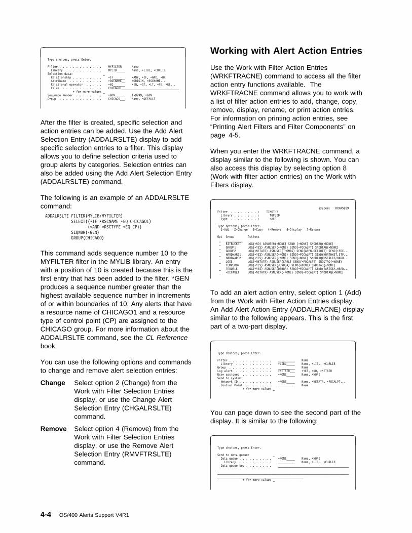
à ð Type choices, press Enter.
Filter . . . . . . . . . . . . . MYFILTER Name
Library . . . . . . . . . . . MYLIB_____ Name, \LIBL, \CURLIB
Selection data: _
Relationship . . . . . . . . . \IF_______ \ANY, \IF, \AND, \OR
Attribute . . . . . . . . . . \RSCNAME__ \ORIGIN, \RSCNAME...
Relational operator . . . . . \EQ_______ \EQ, \GT, \LT, \NE, \GE...
Value . . . . . . . . . . . . CHICAGO1__________________________________
+ for more values _
Sequence Number . . . . . . . . \GEN______ 1-9999, \GEN
Group . . . . . . . . . . . . . CHICAGO___ Name, \DEFAULT
After the filter is created, specific selection andaction entries can be added. Use the Add AlertSelection Entry (ADDALRSLTE) display to addspecific selection entries to a filter. This displayallows you to define selection criteria used togroup alerts by categories. Selection entries canalso be added using the Add Alert Selection Entry(ADDALRSLTE) command.
The following is an example of an ADDALRSLTEcommand: ADDALRSLTE FILTER(MYLIB/MYFILTER)
SELECT((\IF \RSCNAME \EQ CHICAGO1)
(\AND \RSCTYPE \EQ CP))
SEQNBR(\GEN)
GROUP(CHICAGO)
This command adds sequence number 10 to theMYFILTER filter in the MYLIB library. An entrywith a position of 10 is created because this is thefirst entry that has been added to the filter. *GENproduces a sequence number greater than thehighest available sequence number in incrementsof or within boundaries of 10. Any alerts that havea resource name of CHICAGO1 and a resourcetype of control point (CP) are assigned to theCHICAGO group. For more information about theADDALRSLTE command, see the CL Referencebook.
You can use the following options and commandsto change and remove alert selection entries:
Change Select option 2 (Change) from theWork with Filter Selection Entriesdisplay, or use the Change AlertSelection Entry (CHGALRSLTE)command.
Remove Select option 4 (Remove) from theWork with Filter Selection Entriesdisplay, or use the Remove AlertSelection Entry (RMVFTRSLTE)command.
Working with Alert Action Entries
Use the Work with Filter Action Entries(WRKFTRACNE) command to access all the filteraction entry functions available. TheWRKFTRACNE command allows you to work witha list of filter action entries to add, change, copy,remove, display, rename, or print action entries.For information on printing action entries, see“Printing Alert Filters and Filter Components” onpage 4-5.
When you enter the WRKFTRACNE command, adisplay similar to the following is shown. You canalso access this display by selecting option 8(Work with filter action entries) on the Work withFilters display.
à ð System: RCHAS2ð9
Filter . . . . . . . . : TIMOTHY
Library . . . . . . . : TGFLIB
Type . . . . . . . . : \ALR
Type options, press Enter.
1=Add 2=Change 3=Copy 4=Remove 5=Display 7=Rename
Opt Group Actions
_ __________
_ BITBUCKET LOG(\NO) ASNUSER(\NONE) SEND (\NONE) SNDDTAQ(\NONE)
_ GROUP1 LOG(\YES) ASNUSER(\NONE) SEND(\FOCALPT) SNDDTAQ(\NONE)
_ GROUP2 LOG(\NETATR) ASNUSER(THOMAS) SEND(APPN.DETROIT) SEND(\FOC...
_ HARDWARE1 LOG(\YES) ASNUSER(\NONE) SEND(\FOCALPT) SEND(NORTHWST.STP...
_ HARDWARE2 LOG(\YES) ASNUSER(\NONE) SEND(\NONE) SNDDTAQ(USERLIB/HARD...
_ JOES LOG(\NETATR) ASNUSER(CARL) SEND(\FOCALPT) SNDDTAQ(\NONE)
_ TEMPLOOK LOG(\YES) ASNUSER(JOSHUA) SEND(\NONE) SNDDTAQ(\NONE)
_ TROUBLE LOG(\YES) ASNUSER(DEBRA) SEND(\FOCALPT) SEND(EASTSEA.HEAD...
_ \DEFAULT LOG(\NETATR) ASNUSER(\NONE) SEND(\FOCALPT) SNDDTAQ(\NONE)
To add an alert action entry, select option 1 (Add)from the Work with Filter Action Entries display.An Add Alert Action Entry (ADDALRACNE) displaysimilar to the following appears. This is the firstpart of a two-part display.
à ð Type choices, press Enter.
Filter . . . . . . . . . . . . . __________ Name
Library . . . . . . . . . . . \LIBL_____ Name, \LIBL, \CURLIB
Group . . . . . . . . . . . . . __________ Name
Log alert . . . . . . . . . . . \NETATR___ \YES, \NO, \NETATR
User assigned . . . . . . . . . \NONE_____ Name, \NONE
Send to system:
Network ID . . . . . . . . . . \NONE_____ Name, \NETATR, \FOCALPT...
Control Point . . . . . . . . __________ Name
+ for more values _
You can page down to see the second part of thedisplay. It is similar to the following:
à ð Type choices, press Enter.
Send to data queue: _
Data queue . . . . . . . . . . \NONE_____ Name, \NONE
Library . . . . . . . . . . __________ Name, \LIBL, \CURLIB
Data queue key . . . . . . . . __________________________________________
______________________________________________________________________________
______________________________________________________________________________
___________________________________________________
+ for more values _
4-4 OS/400 Alerts Support V4R1
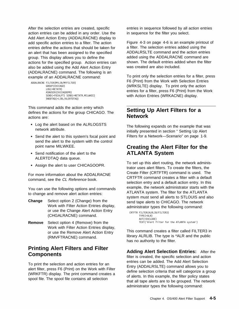
After the selection entries are created, specificaction entries can be added in any order. Use theAdd Alert Action Entry (ADDALRACNE) display toadd specific action entries to a filter. The actionentries define the actions that should be taken foran alert that has been assigned to the specifiedgroup. This display allows you to define theactions for the specified group. Action entries canalso be added using the Add Alert Action Entry(ADDALRACNE) command. The following is anexample of an ADDALRACNE command: ADDALRACNE FILTER(MYLIB/MYFILTER)
GROUP(CHICAGO)
LOG(\NETATR)
ASNUSER(CHICAGOOPR)
SEND(\FOCALPT) SEND(\NETATR.MILWKEE)
SNDDTAQ(\LIBL/ALERTDTAQ)
This command adds the action entry whichdefines the actions for the group CHICAGO. Theactions are:
� Log the alert based on the ALRLOGSTSnetwork attribute.
� Send the alert to this system's focal point andsend the alert to the system with the controlpoint name MILWKEE.
� Send notification of the alert to theALERTDTAQ data queue.
� Assign the alert to user CHICAGOOPR.
For more information about the ADDALRACNEcommand, see the CL Reference book.
You can use the following options and commandsto change and remove alert action entries:
Change Select option 2 (Change) from theWork with Filter Action Entries display,or use the Change Alert Action Entry(CHGALRACNE) command.
Remove Select option 4 (Remove) from theWork with Filter Action Entries display,or use the Remove Alert Action Entry(RMVFTRACNE) command.
Printing Alert Filters and FilterComponents
To print the selection and action entries for analert filter, press F6 (Print) on the Work with Filter(WRKFTR) display. The print command creates aspool file. The spool file contains all selection
entries in sequence followed by all action entriesin sequence for the filter you select.
Figure 4-3 on page 4-6 is an example printout ofa filter. The selection entries added using theADDALRSLTE command and the action entriesadded using the ADDALRACNE command areshown. The default entries added when the filterwas created are also included.
To print only the selection entries for a filter, pressF6 (Print) from the Work with Selection Entries(WRKSLTE) display. To print only the actionentries for a filter, press F6 (Print) from the Workwith Action Entries (WRKACNE) display.
Setting Up Alert Filters for aNetwork
The following expands on the example that wasinitially presented in section “ Setting Up AlertFilters for a Network—Scenario” on page 1-9.
Creating the Alert Filter for theATLANTA System
To set up this alert routing, the network adminis-trator uses alert filters. To create the filters, theCreate Filter (CRTFTR) command is used. TheCRTFTR command creates a filter with a defaultselection entry and a default action entry. In thisexample, the network administrator starts with theATLANTA system. The filter for the ATLANTAsystem must send all alerts to STLOUIS and alsosend tape alerts to CHICAGO. The networkadministrator types the following command: CRTFTR FILTER(ALRLIB/FILTER3)
TYPE(\ALR)
AUT(\EXCLUDE)
TEXT('Alert filter for the ATLANTA system')
This command creates a filter called FILTER3 inlibrary ALRLIB. The type is *ALR and the publichas no authority to the filter.
Adding Alert Selection Entries: After thefilter is created, the specific selection and actionentries can be added. The Add Alert SelectionEntry (ADDALRSLTE) command allows you todefine selection criteria that will categorize a groupof alerts. In this example, the filter policy statesthat all tape alerts are to be grouped. The networkadministrator types the following command:
Chapter 4. OS/400 Alert Filter Support 4-5
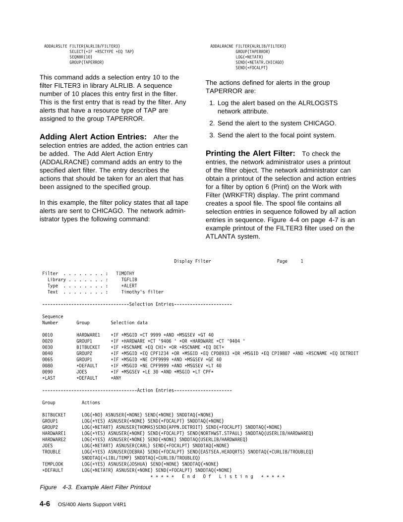
ADDALRSLTE FILTER(ALRLIB/FILTER3)
SELECT(\IF \RSCTYPE \EQ TAP)
SEQNBR(1ð)
GROUP(TAPERROR)
This command adds a selection entry 10 to thefilter FILTER3 in library ALRLIB. A sequencenumber of 10 places this entry first in the filter.This is the first entry that is read by the filter. Anyalerts that have a resource type of TAP areassigned to the group TAPERROR.
Adding Alert Action Entries: After theselection entries are added, the action entries canbe added. The Add Alert Action Entry(ADDALRACNE) command adds an entry to thespecified alert filter. The entry describes theactions that should be taken for an alert that hasbeen assigned to the specified group.
In this example, the filter policy states that all tapealerts are sent to CHICAGO. The network admin-istrator types the following command:
ADDALRACNE FILTER(ALRLIB/FILTER3)
GROUP(TAPERROR)
LOG(\NETATR)
SEND(\NETATR.CHICAGO)
SEND(\FOCALPT)
The actions defined for alerts in the groupTAPERROR are:
1. Log the alert based on the ALRLOGSTSnetwork attribute.
2. Send the alert to the system CHICAGO.
3. Send the alert to the focal point system.
Printing the Alert Filter: To check theentries, the network administrator uses a printoutof the filter object. The network administrator canobtain a printout of the selection and action entriesfor a filter by option 6 (Print) on the Work withFilter (WRKFTR) display. The print commandcreates a spool file. The spool file contains allselection entries in sequence followed by all actionentries in sequence. Figure 4-4 on page 4-7 is anexample printout of the FILTER3 filter used on theATLANTA system.
Display Filter Page 1
Filter . . . . . . . . : TIMOTHY
Library . . . . . . . : TGFLIB
Type . . . . . . . . : \ALERT
Text . . . . . . . . : Timothy's filter
---------------------------------Selection Entries----------------------
Sequence
Number Group Selection data
ðð1ð HARDWARE1 \IF \MSGID \CT 9999 \AND \MSGSEV \GT 4ð
ðð2ð GROUP1 \IF \HARDWARE \CT '94ð6 ' \OR \HARDWARE \CT '94ð4 '
ðð3ð BITBUCKET \IF \RSCNAME \EQ CHI\ \OR \RSCNAME \EQ DET\
ðð4ð GROUP2 \IF \MSGID \EQ CPF1234 \OR \MSGID \EQ CPD8933 \OR \MSGID \EQ CPI98ð7 \AND \RSCNAME \EQ DETROIT
ðð65 GROUP1 \IF \MSGID \NE CPF9999 \AND \MSGSEV \GE 4ð
ðð8ð \DEFAULT \IF \MSGID \NE CPF9999 \AND \MSGSEV \LT 4ð
ðð9ð JOES \IF \MSGSEV \LE 3ð \AND \MSGID \LT CPF\
\LAST \DEFAULT \ANY
------------------------------------Action Entries----------------------
Group Actions
BITBUCKET LOG(\NO) ASNUSER(\NONE) SEND(\NONE) SNDDTAQ(\NONE)
GROUP1 LOG(\YES) ASNUSER(\NONE) SEND(\FOCALPT) SNDDTAQ(\NONE)
GROUP2 LOG(\NETART) ASNUSER(THOMAS)SEND(APPN.DETROIT) SEND(\FOCALPT) SNDDTAQ(\NONE)
HARDWARE1 LOG(\YES) ASNUSER(\NONE) SEND(\FOCALPT) SEND(NORTHWST.STPAUL) SNDDTAQ(USERLIB/HARDWAREQ)
HARDWARE2 LOG(\YES) ASNUSER(\NONE) SEND(\NONE) SNDDTAQ(USERLIB/HARDWAREQ)
JOES LOG(\NETART) ASNUSER(CARL) SEND(\FOCALPT) SNDDTAQ(\NONE)
TROUBLE LOG(\YES) ASNUSER(DEBRA) SEND(\FOCALPT) SEND(EASTSEA.HEADQRTS) SNDDTAQ(\CURLIB/TROUBLEQ)
SNDDTAQ(\LIBL/TEMP) SNDDTAQ(\CURLIB/TROUBLEQ)
TEMPLOOK LOG(\YES) ASNUSER(JOSHUA) SEND(\NONE) SNDDTAQ(\NONE)
\DEFAULT LOG(\NETATR) ASNUSER(\NONE) SEND(\FOCALPT) SNDDTAQ(\NONE)
\ \ \ \ \ E n d O f L i s t i n g \ \ \ \ \
Figure 4-3. Example Alert Filter Printout
4-6 OS/400 Alerts Support V4R1

Display Filter Page 1
Filter . . . . . . . . : FILTER3
Library . . . . . . . : ALRLIB
Type . . . . . . . . : \ALR
Text . . . . . . . . : Alert filter for the ATLANTA system
---------------------------------Selection Entries----------------------
Sequence
Number Group Selection data
ðð1ð TAPERROR \IF \RSCTYPE \EQ TAP
\LAST \DEFAULT \ANY
------------------------------------Action Entries----------------------
Group Actions
TAPERROR LOG(\NETATR) ASNUSER(\NONE) SEND(\NETATR.CHICAGO) SEND(\FOCALPT) SNDDTAQ(\NONE)
\DEFAULT LOG(\NETATR) ASNUSER(\NONE) SEND(\FOCALPT) SNDDTAQ(\NONE)
\ \ \ \ \ E n d O f L i s t i n g \ \ \ \ \
Figure 4-4. Example Alert Filter Used on the ATLANTA System
Creating the Alert Filter for theSEATTLE System
The alert filter for the SEATTLE system is thesame as for the ATLANTA system.
Creating the Alert Filter for theCHICAGO System
To create the filter for the CHICAGO system, thenetwork administrator reviews the filter policy forthat system. All tape-related alerts from SEATTLE,ATLANTA, and STLOUIS are received byCHICAGO. All CHICAGO alerts are sent to thefocal point STLOUIS for processing. Figure 4-5 onpage 4-8 is an example printout of the FILTER4filter used on the CHICAGO system.
Creating the Alert Filter for theSTLOUIS System
The last filter to add is for the focal point systemSTLOUIS. To create the filter for the STLOUISsystem, the network administrator reviews the filterpolicy for that system. All alerts from all systemsare forwarded to STLOUIS. Tape alerts are sentto CHICAGO.
After creating the filter and adding the selectionand action entries, the network administrator printsout a copy of the STLOUIS filter. Figure 4-6 onpage 4-9 is an example printout of the FILTER1filter used on the focal point STLOUIS system.
Figure 4-6 on page 4-9 shows that the local alertsand the received alerts are filtered through theFILTER1 filter. The filter definition states that alltape alerts originating at the local system areassigned to the TAPERROR group. The filter defi-nition also sends a notification of all alerts fromthe TAPERROR group to the ALERTDTAQ dataqueue and sends them to the CHICAGO system.All other alerts are logged in the ALERTDTAQdata queue and remain on the STLOUIS system.
The complete alert routing for the network isshown in Figure 4-7 on page 4-10.
Using a Systems ManagementApplication with Alert Filters
In addition to demonstrating alert routing, thenetwork described in Figure 4-7 on page 4-10shows how a systems management applicationcan use filters.
The network administrator can track how manyalerts of each type are created on each system inthe network. To do this, the network administratorasks a systems programmer to write anaccounting application that monitors the dataqueue. The network administrator designs thefilters to forward notifications of alerts from allsystems to the STLOUIS system and to add notifi-cation of those alerts to the ALERTDTAQ dataqueue. The systems management applicationmonitors the data queue. Using the notification
Chapter 4. OS/400 Alert Filter Support 4-7

Display Filter Page 1
Filter . . . . . . . . : FILTER4
Library . . . . . . . : ALRLIB
Type . . . . . . . . : \ALR
Text . . . . . . . . : Alert filter for the CHICAGO system
---------------------------------Selection Entries----------------------
Sequence
Number Group Selection data
ðð1ð LOCALTAPE \IF \RSCTYPE \EQ TAP \AND \ORIGIN \EQ L
ðð1ð REMOTETAPE \IF \RSCTYPE \EQ TAP
\LAST \DEFAULT \ANY
------------------------------------Action Entries----------------------
Group Actions
LOCALTAPE LOG(\NETATR) ASNUSER(TAPEOPR) SEND(\FOCALPT) SNDDTAQ(\NONE)
REMOTETAPE LOG(\NETATR) ASNUSER(TAPEOPR) SEND(\NONE) SNDDTAQ(\NONE)
\DEFAULT LOG(\NETATR) ASNUSER(\NONE) SEND(\FOCALPT) SNDDTAQ(\NONE)
\ \ \ \ \ E n d O f L i s t i n g \ \ \ \ \
Figure 4-5. Example Alert Filter Used on the CHICAGO System
information in the data queue, the applicationproduces a weekly report that shows the numberof alerts of each type that were created on each
system for the preceding week. You can use theQALRTVA API to retrieve the alerts from the alertdatabase from notifications on the data queue.
4-8 OS/400 Alerts Support V4R1
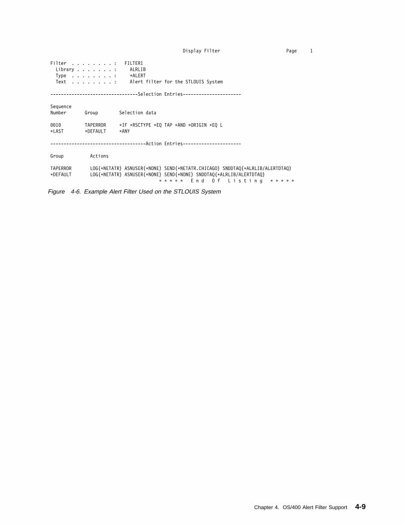
Display Filter Page 1
Filter . . . . . . . . : FILTER1
Library . . . . . . . : ALRLIB
Type . . . . . . . . : \ALERT
Text . . . . . . . . : Alert filter for the STLOUIS System
---------------------------------Selection Entries----------------------
Sequence
Number Group Selection data
ðð1ð TAPERROR \IF \RSCTYPE \EQ TAP \AND \ORIGIN \EQ L
\LAST \DEFAULT \ANY
------------------------------------Action Entries----------------------
Group Actions
TAPERROR LOG(\NETATR) ASNUSER(\NONE) SEND(\NETATR.CHICAGO) SNDDTAQ(\ALRLIB/ALERTDTAQ)
\DEFAULT LOG(\NETATR) ASNUSER(\NONE) SEND(\NONE) SNDDTAQ(\ALRLIB/ALERTDTAQ)
\ \ \ \ \ E n d O f L i s t i n g \ \ \ \ \
Figure 4-6. Example Alert Filter Used on the STLOUIS System
Chapter 4. OS/400 Alert Filter Support 4-9

FILTER1
LocalAlerts
Focal Point
EntryPoint
SEATTLECHICAGOATLANTA
FILTER2
Test System
EntryPoint
FILTER3
LocalAlerts
All Alerts
Legend:
LocalAlerts
SEATTLEAS/400 System
ATLANTAAS/400 System
CHICAGOAS/400 System
STLOUISAS/400 System
TAP* Alerts Only
EntryPoint
FILTER4
Tape Operator(TAPEOPR)
RV2P904-1
LocalAlerts
TapeAlerts
Sphere ofControl
Figure 4-7. Example Alert Network Using Alert Filters
4-10 OS/400 Alerts Support V4R1

Appendixes
Copyright IBM Corp. 1997

OS/400 Alerts Support V4R1

Appendix A. Sample Procedures for OS/400 Alerts
You may find it useful to add your own alertdescriptions for user-defined messages or tochange or add to the alert descriptions forIBM-supplied messages. For example, if you havean application program that sends messages tothe network operator, by defining your own alertdescriptions you can provide the operator withspecific information about the cause of theproblem and specify your own recovery procedure.
You need to create your own alert table to addalert descriptions for user-defined messages. Tochange or add to the alert descriptions forIBM-supplied messages, you need to change theIBM-supplied alert table (for example,QCPFMSG).
Examples of Creating an AlertTable
In the following example, the CRTALRTBLcommand is used to create alert tableALRTBLNBR1 in library ALRTBLLIB.
CRTALRTBL ALRTBL(ALRTBLLIB/ALRTBLNBR1)
AUT(\CHANGE)
LICPGM(5738SS1)
LICPGMTXT('OS/4ðð-Customer version')
TEXT('This is the first ALRTBL created')
The public has *CHANGE authority to the table.The program associated with this alert table is theOS/400 licensed program. The alert includes therelease and level information for the OS/400program, along with the text, OS/4ðð-Customer
version.
In the following example, the CRTALRTBLcommand is used to create alert tableCUSTALRTBL in library ALRTBLLIB.
CRTALRTBL ALRTBL(ALRTBLLIB/CUSTALRTBL)
AUT(\CHANGE)
LICPGM(CUSTðð1)
LICPGMTXT('Customer application ðð1')
TEXT('Customer application alert table')
The public has *CHANGE authority to the table.The program associated with this alert table isCUST001. The licensed program ID CUST001and the text Customer application ðð1 are sent
in the alert. Since CUST001 is not a recognizedlicensed program, no release or level informationis sent in the alert.
An Example of Adding an AlertDescription
Figure A-1 defines an alertable message and thealert for the message. The message APP1000 isin message file CAPPL1 in library CAPPL1LIB.The alert table name is CAPPL1, the same nameas the message file.
In Figure A-1, the message file and the alert tableare both in the CAPPL1LIB library. Although theymust use the same name, they are not required tobe in the same library. The alert table does haveto be in the library list of the job that sends themessage that causes the alert.
CRTLIB LIB(CAPPL1LIB) TEXT('Customer application 1 library')
ADDLIBLE LIB(CAPPL1LIB)
CRTMSGF MSGF(CAPPL1LIB/CAPPL1)
TEXT('Customer application 1 - message file')
CRTALRTBL ALRTBL(CAPPL1LIB/CAPPL1) LICPGM(CAPPL1ð)
LICPGMTXT('Customer Application ððð1')
TEXT('Customer Application 1 - alert table')
ADDMSGD MSGID(APP1ððð) MSGF(CAPPL1LIB/CAPPL1)
MSG('Application program &1; failed while writing to
file &2; library &3; with reason code &4;')
SECLVL('The information could not be written to the file.
The file is possibly full.')
SEV(8ð)
FMT((\CHAR 1ð) (\CHAR 1ð) (\CHAR 1ð) (\BIN 2))
ALROPT(\IMMED)
ADDALRD MSGID(APP1ððð) ALRTBL(CAPPL1LIB/CAPPL1)
ALRTYPE(ð1) ALRD(21ðð)
PBLCAUSE(1ððð 7ðð4 7ðð1)
CAUSE((\USER 73Að Dð '&2');
(\USER 73A1 Dð '&2');
(\FAILURE 1ðE1 \NONE \NODATA
\NONE \NODATA
\NONE \NODATA
\SNDSFW))
ACTION((\USER 32Cð Dð '&2'; ðð '&3');
(\USER 13ðð)
(\FAILURE 32Cð A6 '&1'; ðE '&4');
(\FAILURE FðAð 2ð 'APP1ððð')
(\FAILURE Fðð8))
Figure A-1. Example Alertable Message Definition andAlert
Copyright IBM Corp. 1997 A-1

Figure A-1 defines a recommended action 32Cð,which requires 2 detailed data qualifiers. Thedetailed data ID A6 uses message substitution var-iable &1 as detailed data. The detailed data ID ðE
uses message substitution variable &4 as detaileddata.
Recommended action FðAð specifies detailed data'APP1ððð'.
Recommended action Fðð8 specifies no detaileddata.
Example of Alertable Messagewith Substitution Variables
When a message is sent using the Send ProgramMessage (SNDPGMMSG) command, the alertdescription and message description can be dis-played. Using the alert description and messagedescription from the previous example, the fol-lowing message is shown in the QSYSOPRmessage queue:
à ð System: ROCHSTR
Queue . . . . . : QSYSOPR Program . . . . : \DSPMSG
Library . . . : QSYS Library . . . :
Severity . . . : 7ð Delivery . . . : \BREAK
Press Enter to continue.
Application program CAPPLððð1 failed while writing to file CSTFILA library
DATALIBA with reason code 34.
The message is defined as alertable and amessage is created. Using the WRKALR
command, and selecting option 5 (Display recom-mended actions), a display similar to the followingis shown:
à ðDisplay Recommended Actions
System: ROCHSTR
----------Resource Hierarchy-----------
Resource Name Resource Type
ROCHSTR CP
User causes . . . . . . : File full: File name CSTFILA
File needs reorganization: File name CSTFILA
Actions . . . . . . . . : Report the following
File name CSTFILA
DATALIBA
Correct then retry
Failure causes . . . . : Software program Customer Application ððð1
Actions . . . . . . . . : Report the following
Program CAPPLððð1
More...
The alert is created using the alert description forthe message ID APP1ððð in alert table CAPPL1.Substitution variables are filled in. The productidentifier Customer Application ððð1 is filled in.
Using the WRKALR command, and selectingoption 8 (Display alert detail), the alert type, alertdescription, and probable cause are shown.
à ð System: ROCHSTR
----------Resource Hierarchy-----------
Resource Name Resource Type
ROCHSTR CP
Logged date/time . . . . . . : ð1/11/91 ð9:49:44
Problem date/time . . . . . : ð1/11/91 ð9:49:44
Assigned user . . . . . . . :
Group filter . . . . . . . . :
Alert type . . . . . . . . . : Permanent
Alert description . . . . . : Software program error
Probable cause . . . . . . . : Software program
A-2 OS/400 Alerts Support V4R1

Appendix B. IBM-Supplied Alertable Messages
This appendix lists the alertable messagesshipped with the OS/400 licensed program in theQCPFMSG message file. A message is alertable ifthe alert option (ALROPT) parameter is set to oneof the following:
*IMMED Send alert immediately
*DEFER Send alert after local problem analysis
*UNATTEND Send alert for an unattended system
QCPFMSG Messages withALROPT(*IMMED)CPA57A1 Controller &24; contact not successful.
(C R)
CPA57EB Controller &24; not found on token-ringnetwork. (C G R)
CPA57EC Controller &24; failed. Probable remotestation problem. (C G R)
CPA57EF Controller &24; contact not successful.Probable remote station problem. (C R)
CPA57E1 All sessions to controller &24; failed.Data may be lost. (C G R)
CPA57E4 Controller &24; contact not successfulon line &23; (C R)
CPA5748 Controller &24; failed. Probable X.25network problem. (C G R)
CPA5779 Controller &24; on line &23; not con-tacted. (C R)
CPA579A Controller &24; contact not successful.(C R)
CPA579B Controller &24; contact not successful.Probable X.25 network problem. (C GR)
CPA58AA Controller &24; failed. Data bufferexceeded (C G R)
CPA58AB Contact not successful for controller&24; Data buffer exceeded. (C G R)
CPA58AC Contact not successful for controller&24; Data buffer exceeded. (C R)
CPA58ED Controller &24; failed. Probable localsystem problem. (C G R)
CPA58EE Line &23; failed. Probable cabling orhardware problem. (C G R)
CPA58E4 Call on line &23; failed, packet modeconnection not supported by thenetwork (C N R).
CPA58F7 Line &23; failed while attached tonetwork interface &30; Network is notready. (C G R)
CPA58F8 Line &23; contact not successful onnetwork interface &30; Network is notready. (C N R)
CPA5808 Cannot communicate with device &25;Probable local system problem. (C RG)
CPA583A Controller &24; failed. Resources notsufficient. (C G R)
CPA5841 Controller &24; failed. Probable remotesystem problem. (C G R)
CPA5878 Internal system failure. Contact notsuccessful on controller &24; (C R)
CPA5879 Contact not successful for controller&24; Internal system failure. (C G R)
CPA59DE Controller &24; contact not successful.Logical channel recovering from error.(C G R)
CPA59DF Controller &24; contact not successful.Probable local system problem. (C R)
CPA59D0 Line &23; failed. HDLC link discon-nected. (C G R)
CPA59D5 Line &23; failed. HDLC link discon-nected. (C G R)
CPA59F1 Internal system failure on line &23; (CG R)
CPA59F3 Controller &24; failed. Internal systemfailure. (C G R)
CPA59F8 Internal system failure on network inter-face &30; (C G R)
CPA596F Controller &24; contact not successfulon line &23; (C R)
CPC3A34 Abnormal end of SNADS *SVDSsender &3/&2/&1; serving distributionqueue &4;
Copyright IBM Corp. 1997 B-1
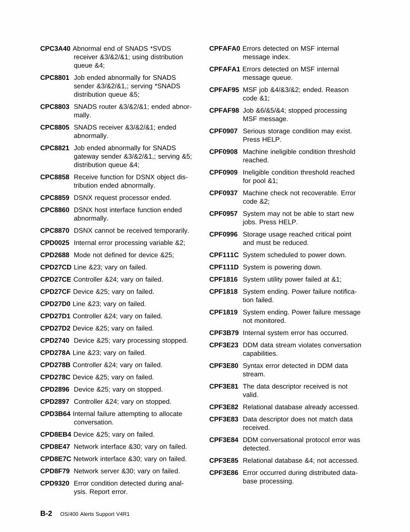
CPC3A40 Abnormal end of SNADS *SVDSreceiver &3/&2/&1; using distributionqueue &4;
CPC8801 Job ended abnormally for SNADSsender &3/&2/&1,; serving *SNADSdistribution queue &5;
CPC8803 SNADS router &3/&2/&1; ended abnor-mally.
CPC8805 SNADS receiver &3/&2/&1; endedabnormally.
CPC8821 Job ended abnormally for SNADSgateway sender &3/&2/&1,; serving &5;distribution queue &4;
CPC8858 Receive function for DSNX object dis-tribution ended abnormally.
CPC8859 DSNX request processor ended.
CPC8860 DSNX host interface function endedabnormally.
CPC8870 DSNX cannot be received temporarily.
CPD0025 Internal error processing variable &2;
CPD2688 Mode not defined for device &25;
CPD27CD Line &23; vary on failed.
CPD27CE Controller &24; vary on failed.
CPD27CF Device &25; vary on failed.
CPD27D0 Line &23; vary on failed.
CPD27D1 Controller &24; vary on failed.
CPD27D2 Device &25; vary on failed.
CPD2740 Device &25; vary processing stopped.
CPD278A Line &23; vary on failed.
CPD278B Controller &24; vary on failed.
CPD278C Device &25; vary on failed.
CPD2896 Device &25; vary on stopped.
CPD2897 Controller &24; vary on stopped.
CPD3B64 Internal failure attempting to allocateconversation.
CPD8EB4 Device &25; vary on failed.
CPD8E47 Network interface &30; vary on failed.
CPD8E7C Network interface &30; vary on failed.
CPD8F79 Network server &30; vary on failed.
CPD9320 Error condition detected during anal-ysis. Report error.
CPFAFA0 Errors detected on MSF internalmessage index.
CPFAFA1 Errors detected on MSF internalmessage queue.
CPFAF95 MSF job &4/&3/&2; ended. Reasoncode &1;
CPFAF98 Job &6/&5/&4; stopped processingMSF message.
CPF0907 Serious storage condition may exist.Press HELP.
CPF0908 Machine ineligible condition thresholdreached.
CPF0909 Ineligible condition threshold reachedfor pool &1;
CPF0937 Machine check not recoverable. Errorcode &2;
CPF0957 System may not be able to start newjobs. Press HELP.
CPF0996 Storage usage reached critical pointand must be reduced.
CPF111C System scheduled to power down.
CPF111D System is powering down.
CPF1816 System utility power failed at &1;
CPF1818 System ending. Power failure notifica-tion failed.
CPF1819 System ending. Power failure messagenot monitored.
CPF3B79 Internal system error has occurred.
CPF3E23 DDM data stream violates conversationcapabilities.
CPF3E80 Syntax error detected in DDM datastream.
CPF3E81 The data descriptor received is notvalid.
CPF3E82 Relational database already accessed.
CPF3E83 Data descriptor does not match datareceived.
CPF3E84 DDM conversational protocol error wasdetected.
CPF3E85 Relational database &4; not accessed.
CPF3E86 Error occurred during distributed data-base processing.
B-2 OS/400 Alerts Support V4R1

CPF3E87 Permanent error condition detected.
CPF3E88 The SQL cursor had been previouslyopened at the remote system.
CPF3E89 SQL cursor not open for an attemptedremote operation.
CPF4168 Error on device or location &5; in file&2; in &3;
CPF4262 Feedback code not recognized ondevice &4;
CPF4509 Feedback code not recognized ondevice &4;
CPF4524 Error on device &4; Device responsecode is &6;
CPF4527 Error on device &4; Device responsecode is &6;
CPF4541 MODLUD reset ended request. Internalfailure in system.
CPF4584 Transmit not allowed until previousresponse received.
CPF5105 Error on file &2; in library &3; on device&4;
CPF5406 Data passed on SNADS distribution notvalid. Internal failure in system.
CPF5453 Input/Output error on device &4;Internal failure in system.
CPF594F The APPN congestion threshold hasbeen reached for the system.
CPF8BC0 DDI MAC path change event occurredon line &23,; station &40;
CPF8B03 Excessive recoverable token-ring errorson line &23; for adapter &40; or &41;
CPF8B13 Excessive recoverable token-ring errorson line &23,; adapter &40;
CPF8B26 Receiver congestion reported byadapter &40; on line &23;
CPF8B27 Congested condition ended at adapter&40,; line &23;
CPF8B28 Token-ring line &23; beaconing.Recovery in process.
CPF8B29 Token-ring line &23; beaconing.Recovery in process.
CPF8B30 Token-ring line &23; beaconing.Recovery in process.
CPF8B31 Token-ring line &23; beaconing.Recovery procedures failed.
CPF8B32 Token-ring line &23; beaconing.Recovery procedures failed.
CPF8B33 Token-ring line &23; beaconing.Recovery procedures failed.
CPF8B35 Token-ring line &23; manually recov-ered. Adapters &40; and &41;removed.
CPF8B36 Token-ring line &23; manually recov-ered. Adapter &40; removed.
CPF8B85 MAC not-copied condition occurring online &23,; station &40;
CPF8B90 DDI frame error ratio exceeds alarmthreshold on line &23,; station &40;
CPF8B92 DDI link error rate on line &23,; adapter&40,; exceeds alarm threshold.
CPF8B97 DDI elasticity buffer error conditionreported on line &23,; station &40;
CPF8804 Error occurred during distribution proc-essing.
CPF8807 Error occurred while using QSNADSjournal.
CPF8808 SNADS cannot allocate more queuespace.
CPF8809 Errors detected on SNADS internalqueues.
CPF8810 An unrecoverable error occurred in aSNADS module.
CPF8811 Errors occurred in SNADS receive dis-tribution processor.
CPF8812 Error occurred while processing distrib-ution queues.
CPF8824 Error occurred during inbound gatewaydistribute processing.
CPF8825 Data passed on SNADS inboundgateway distribution not valid. Internalfailure in system.
CPF8861 Not able to establish communicationswith NetView Distribution Managerhost.
CPF8862 DSNX host interface ended abnormally.
CPF8863 DSNX receive function ended abnor-mally.
Appendix B. IBM-Supplied Alertable Messages B-3

CPF8864 Not able to open data base file &1;containing DSNX correlation table.
CPF8865 DSNX had a severe error whileattempting to manage storage.
CPF8866 DSNX request exceeded systemstorage available.
CPF8871 SNADS object is damaged.
CPF9E15 Error in license management function.
CPF93C0 Software error logging not active.
CPIAFA7 Error occurred while using MSF log.
CPI0906 *ATTENTION* Controlling subsystem&1; should be started.
CPI0961 Uninterruptible power supply (UPS) nolonger attached.
CPI0962 Uninterruptible power supply (UPS)now attached.
CPI0964 Weak battery condition exists.
CPI0965 Failure of battery backup feature insystem unit.
CPI0966 Failure of the battery backup feature inexpansion unit.
CPI0973 Weak battery condition no longerexists.
CPI0974 UPS has been bypassed.
CPI0975 UPS no longer bypassed.
CPI0976 Notification of message &1; failed.
CPI1E62 &1; backup not successful or not com-plete (&2);
CPI1117 Damaged job schedule &1; in library&2; deleted.
CPI1153 System password bypass periodended.
CPI1154 System password bypass period willend in &5; days.
CPI1165 One or more device parity protectedunits still not fully operational.
CPI1166 Units with device parity protection fullyoperational.
CPI1303 Insufficient storage in machine pool tostart job &3/&2/&1;
CPI3A32 Recovery failed for SNADS *SVDSsender &3/&2/&1; serving distributionqueue &4;
CPI3CEE QUSEXRGOBJ in QUSRSYS isdamaged.
CPI3CEF Exit registration facility repository is full.
CPI573A This message is not used.
CPI573B Network server &30; failed.
CPI573D Network server &30; failed.
CPI573F Network server &30; failed.
CPI5807 Device &25; on controller &24; on line&23; failed.
CPI5808 Device &25; on controller &24; on line&23; failed.
CPI59A3 Connection on device &25; failed.Internal system failure.
CPI59A5 Unacknowledged service on device&25; failed. Internal system failure.
CPI59A7 Internal failure during automatic cre-ation of controller description.
CPI59B1 Internal system failure while settingthresholds for line &23;
CPI59CA Internal system failure while settingcounters for line &23;
CPI59C8 Internal system failure while settingcounters for network interface &30;
CPI59D9 Internal operating system error inQLUS job.
CPI59E4 Line &23; failed. Resource already inuse.
CPI59E5 Network interface &30; failed.Resource already in use.
CPI59F1 Line &23; failed. Internal system failure.
CPI59F3 Controller &24; failed. Internal systemfailure.
CPI59F8 Network interface &30; failed. Internalsystem failure.
CPI5903 Network password received for line&23; not valid.
CPI5904 No logical channel available forincoming call on line &23;
CPI591D Device &25; on controller &24; on line&23; failed.
CPI5914 Line &23; failed. Data received in Con-tention State.
B-4 OS/400 Alerts Support V4R1

CPI5915 Device &25; on controller &24; on line&23; failed.
CPI5928 Line &23; could not process an X.25 orlocal area network incoming callrequest.
CPI5932 Internal operating system error inQSYSARB job.
CPI598A Transmission priority mismatchbetween networks.
CPI7B40 Data received from &1;&2; not allowed.
CPI7E1A Cryptographic subsystem &26; failed
CPI7E1F Internal system error detected byresource &26;
CPI7E16 FAX adapter &27; failed.
CPI7E17 Communications error detected by faxadapter &27;
CPI7E2F Cryptographic subsystem &26; failed
CPI7E27 Line &23; has recovered from awrapped configuration
CPI7E3B Fax adapter port &28; failed
CPI7E3C Fax adapter &27; failed
CPI7E42 Error with device &25; on workstationcontroller &24;
CPI7E43 Error with device &25; on workstationcontroller &26;
CPI7E44 Error with device &25; on workstationcontroller &24;
CPI7E5A Ethernet adapter &27; detected arecoverable error.
CPI7E5E Ethernet resource &27; status informa-tion
CPI7E5F Ethernet network adapter &27;detected recoverable error.
CPI7FC9 Network interface &30,; line &23;Threshold Information.
CPI7FF5 Network interface &30; threshold infor-mation. Loss of synchronization errors.
CPI7FF6 Short frame error limit reached onnetwork interface &30;
CPI7FF7 Network interface &30; threshold infor-mation. DTSEIN error.
CPI7FF8 Network interface &30; threshold infor-mation. DTSEOUT error.
CPI7F0A Frame reject type X received onnetwork interface &30;
CPI7F0C Network interface &30; information.Incoming calls rejected limit exceeded.
CPI7F07 Disconnect retry limit reached on line&23; network interface &30; during dis-connect processing.
CPI7F08 Frame reject type W received onnetwork interface &30;
CPI7F1A Frame reject type Y received onnetwork interface &30;
CPI7F1C Frame reject type Z received onnetwork interface &30;
CPI7F33 Network interface &30; threshold infor-mation. Far end code violation.
CPI7F34 Network interface &30; threshold infor-mation. Local end code violation.
CPI7F4A Network interface &30; line &23;threshold information. Send sequencecounter (NS) error.
CPI7F45 Overrun error threshold limit reachedon line &23,; network interface &30;
CPI7F46 Short frame error threshold limitreached on line &23,; network interface&30;
CPI7F47 Aborted frames threshold limit reachedon network interface &30,; line &23;
CPI7F8B A disconnect-mode frame was receivedon network interface &30;
CPI7F8C An unsolicited disconnect-mode framewas received on network interface &30;
CPI7F8F Overrun errors threshold limit reachedon network interface &30;
CPI7F84 Underrun errors threshold limit reachedon network interface &30;
CPI7F85 Aborted frames threshold limit reachedon network interface &30;
CPI7F86 Retransmitted frames limit reached onnetwork interface &30;
CPI7F87 Send sequence errors threshold limitreached on network interface &30;
CPI7F9B Error on network interface &30;
CPI7F9D Line &23; attached to network interface&30,; underrun errors thresholdreached.
Appendix B. IBM-Supplied Alertable Messages B-5

CPI7F9E Retransmitted frames limit reached online &23,; network interface &30;
CPI7F92 A set-asynchronous-balance-mode-extended frame was received on line&23,; network interface &30;
CPI7F93 Disconnect-mode frame with final bit offreceived on line &23; attached tonetwork interface &30;
CPI7F94 Disconnect-mode frame with final bit onreceived on line &23; attached tonetwork interface &30;
CPI8A13 QDOC library nearing system objectlimit.
CPI8A14 QDOC library has exceeded systemobject limit.
CPI8EBA Line &23; threshold information.
CPI8EBB Line &23; threshold information.
CPI8EBC Line &23; threshold information.
CPI8EBE Line &23; threshold information.
CPI8EB0 Line &23; threshold information.
CPI8EB1 Line &23; threshold information.
CPI8EB2 Line &23; threshold information.
CPI8EB3 Line &23; threshold information.
CPI8EB4 Line &23; threshold information.
CPI8EB5 Line &23; threshold information.
CPI8EB6 Line &23; threshold information.
CPI8EB7 Line &23; threshold information.
CPI8EB8 Line &23; threshold information.
CPI8EB9 Line &23; threshold information.
CPI8EC0 Line &23; threshold information.
CPI8EC2 Line &23; threshold information.
CPI8EDE Line &23; status information, thesystem workload may be too heavy.
CPI8EF2 Line &23; threshold information.
CPI8EF3 Line &23; threshold information.
CPI8EF4 Line &23; threshold information.
CPI8EF5 Line &23; threshold information.
CPI8EF6 Line &23; threshold information.
CPI8EF7 Line &23; threshold information.
CPI8EF8 Line &23; threshold information.
CPI8E0A Line &23; threshold information.
CPI8E0B Line &23; threshold information.
CPI8E0C Line &23; threshold information.
CPI8E0D Line &23; threshold information.
CPI8E0E Line &23; threshold information.
CPI8E0F Line &23; threshold information.
CPI8E00 Line &23; threshold information.
CPI8E01 Line &23; threshold information.
CPI8E02 Line &23; threshold information.
CPI8E03 Line &23; threshold information.
CPI8E04 Line &23; threshold information.
CPI8E05 Line &23; threshold information.
CPI8E06 Line &23; threshold information.
CPI8E07 Line &23; threshold information.
CPI8E08 Line &23; threshold information.
CPI8E09 Line &23; threshold information.
CPI8E1A Line &23; threshold information.
CPI8E1B Line &23; threshold information.
CPI8E1C Line &23; threshold information.
CPI8E1D Line &23; threshold information.
CPI8E1E Line &23; threshold information.
CPI8E1F Line &23; threshold information.
CPI8E10 Line &23; threshold information.
CPI8E11 Line &23; threshold information.
CPI8E12 Line &23; threshold information.
CPI8E13 Line &23; threshold information.
CPI8E14 Line &23; threshold information.
CPI8E15 Line &23; threshold information.
CPI8E16 Line &23; threshold information.
CPI8E17 Line &23; threshold information.
CPI8E18 Line &23; threshold information.
CPI8E19 Line &23; threshold information.
CPI8E2A Line &23; threshold information.
CPI8E2B Line &23; threshold information.
CPI8E2C Line &23; threshold information.
CPI8E2D Line &23; threshold information.
CPI8E2E Line &23; threshold information.
B-6 OS/400 Alerts Support V4R1

CPI8E2F Call-Progress-Signal 00 threshold online &23;
CPI8E20 Line &23; threshold information.
CPI8E21 Line &23; threshold information.
CPI8E22 Line &23; threshold information.
CPI8E23 Line &23; threshold information.
CPI8E24 Line &23; threshold information.
CPI8E25 Line &23; threshold information.
CPI8E26 Line &23; threshold information.
CPI8E27 Line &23; threshold information.
CPI8E28 Line &23; threshold information.
CPI8E29 Line &23; threshold information.
CPI8E3A Line &23; threshold information.
CPI8E3B Line &23; threshold information.
CPI8E3C Line &23; threshold information.
CPI8E3D Line &23; threshold information.
CPI8E3E Line &23; threshold information.
CPI8E3F Line &23; threshold information.
CPI8E30 Call-Progress-Signal 01 threshold online &23;
CPI8E31 Call-Progress-Signal 02 threshold online &23;
CPI8E32 Call-Progress-Signal 03 threshold online &23;
CPI8E33 Call-Progress-Signal 04 threshold online &23;
CPI8E34 Line &23; threshold information.
CPI8E35 Line &23; threshold information.
CPI8E36 Line &23; threshold information.
CPI8E37 Line &23; threshold information.
CPI8E38 Line &23; threshold information.
CPI8E39 Line &23; threshold information.
CPI8E40 Line &23; threshold information.
CPI8E41 Line &23; threshold information.
CPI8E42 Line &23; threshold information.
CPI8E43 Line &23; threshold information.
CPI8E44 Line &23; threshold information.
CPI8E45 Line &23; threshold information.
CPI8E46 Line &23; threshold information.
CPI8E7A Line &23; threshold information.
CPI8E70 Line &23; threshold information.
CPI8E71 Line &23; threshold information.
CPI8E72 Line &23; threshold information.
CPI8E73 Line &23; threshold information.
CPI8E74 Line &23; threshold information.
CPI8E75 Line &23; threshold information.
CPI8E76 Line &23; threshold information.
CPI8E77 Line &23; threshold information.
CPI8E78 Line &23; threshold information.
CPI8E79 Line &23; threshold information.
CPI8E8B Line &23; threshold information.
CPI8E8C Line &23; threshold information.
CPI8E80 Line &23; threshold information.
CPI8E81 Line &23; threshold information.
CPI8E82 Line &23; threshold information.
CPI8E83 Line &23; threshold information.
CPI8E84 Line &23; threshold information.
CPI8E85 Line &23; threshold information.
CPI8E88 Line &23; threshold information.
CPI8FB2 Line &23; threshold information.
CPI8FB3 Line &23; threshold information.
CPI8FB4 Line &23; threshold information.
CPI8FC6 Line &23; status information, thesystem work load may be too heavy.
CPI8FDA Line &23; threshold information.
CPI8FDB Line &23; threshold information.
CPI8FDC Line &23; threshold information.
CPI8FDD Line &23; threshold information.
CPI8FDE Line &23; threshold information.
CPI8FDF Line &23; threshold information.
CPI8FD3 Line &23; threshold information.
CPI8FD4 Line &23; threshold information.
CPI8FD5 Line &23; threshold information.
CPI8FD6 Line &23; threshold information.
CPI8FD7 Line &23; threshold information.
Appendix B. IBM-Supplied Alertable Messages B-7

CPI8FD8 Line &23; threshold information.
CPI8FD9 Line &23; threshold information.
CPI8FFF Line &23; threshold information.
CPI8FF2 Line &23; threshold information.
CPI8FF3 Line &23; threshold information.
CPI8FF4 Line &23; threshold information.
CPI8FF5 Line &23; threshold information.
CPI8FF6 Line &23; threshold information.
CPI8FF7 Line &23; threshold information.
CPI8FF8 Line &23; threshold information.
CPI8FF9 Line &23; threshold information.
CPI8F2D Line &23; status information, line isrunning.
CPI8F2E Line &23; status information, line isrunning.
CPI8F2F Line &23; status information, line isrunning.
CPI8F37 Line &23; status information, line isrunning.
CPI8F38 Line &23; status information, line isrunning.
CPI8F4A Line &23; threshold information.
CPI8F4B Line &23; threshold information.
CPI8F4C Line &23; threshold information.
CPI8F4D Line &23; threshold information.
CPI8F4E Line &23; threshold information.
CPI8F4F Line &23; threshold information.
CPI8F5F Line &23; threshold information.
CPI8F50 Line &23; threshold information.
CPI8F51 Line &23; threshold information.
CPI8F53 Line &23; threshold information.
CPI8F54 Error with device &25; on work stationcontroller &24;
CPI8F55 Error with device &25; on work stationcontroller &24;
CPI8F56 Error with device &25; on work stationcontroller &24;
CPI8F58 Error with device &25; on work stationcontroller &24;
CPI8802 Distribution queue &1; error held bysender job.
CPI8804 Error occurred while sending an entryon &1; &2; queue.
CPI8807 Error(s) logged by SNADS while a dis-tribution request was being routed.
CPI8810 SNADS cannot allocate queue space.
CPI8811 Errors detected on SNADS internalqueues.
CPI8813 Error occurred while using QSNADSjournal.
CPI8816 Recovery failed for SNADS sender&3/&2/&1,; serving *SNADS distributionqueue &5;
CPI8822 SNADS &5; distribution queue &4;error held by sender job.
CPI8826 Recovery failed for SNADS gatewaysender &3/&2/&1,; serving &5; distrib-ution queue &4;
CPI8854 DSNX error while journaling.
CPI93B0 Software problem data for &1; hasbeen logged. Refer to help text foradditional information.
CPI93B9 Software problem data for &1; hasbeen logged. Refer to help text foradditional information.
CPI9804 IBM application generated alert: &2;
CPI9805 User application generated alert: &2;
CPI9806 Operator generated alert: &2;
QCPFMSG Messages withALROPT(*DEFER)CPA5201 Hardware failure on device &3;
CPA57AA Call to controller on line &23; notanswered. Probable remote problem.(C G R)
CPA57AB Call from controller on line &23; failed.Probable network or hardware problem.(C G R)
CPA57AD DCE or local hardware on line &23;failed. (C G R)
CPA57AE DCE on line &23; not turned on or notin data mode. (C G R)
B-8 OS/400 Alerts Support V4R1

CPA57AF Dialing digits for controller &24; notvalid. (C R)
CPA57A0 Network interface &30; failed. Unable todetect power source from NT. (C G R)
CPA57A2 Incoming data on line &23; lost. (C GR)
CPA57A3 Controller &24; failed. Probable remotesystem or network problem. (C G R)
CPA57A4 Controller &24; failed. Remote systemproblem. (C G R)
CPA57A5 Call request on line &23; failed. Prob-able network failure. (C G R)
CPA57A6 Controller &24; failed. Remote systemproblem. (C G R)
CPA57A7 Controller &24; failed. Probable remotesystem problem. (C G R)
CPA57A8 Controller &24; failed. Probable remotesystem problem. (C G R)
CPA57A9 Controller &24; failed. Probable remotesystem or network problem. (C G R)
CPA57BA Call request on line &23; to controller&24; failed. Remote modem powermay be off. (C R)
CPA57BB Network rejected call request to con-troller &24; on line &23; (C R)
CPA57BC Controller &24; contact not successful.Probable network problem. (C R)
CPA57BD Call request on line &23; failed. Notifynetwork administrator. (C G R)
CPA57BE Network rejected call request to con-troller &24; on line &23; (C R)
CPA57BF Temporary network congestion whiletrying to contact controller &24; (C R)
CPA57B0 Call to controller &24; on line &23;rejected. Probable network or DCEproblem. (C R)
CPA57B1 Call to controller &24; failed. X.21station busy. (C R)
CPA57B2 Selection signals used to call controller&24; not correct. (C R)
CPA57B3 Parity error on line &23; (C G R)
CPA57B4 Not authorized to call controller &24; online &23; (C R)
CPA57B5 Connection number to controller &24;has changed. (C R)
CPA57B6 Connection number for controller &24;failed. Probable connection number notvalid. (C R)
CPA57B7 Call to controller &24; failed. Probableremote DCE problem. (C R)
CPA57B8 Controller &24; not ready. (C R)
CPA57B9 Controller &24; not ready. (C R)
CPA57CA Attempt to connect with controller &24;exceeded time limit. (C R)
CPA57CB Call to controller &24; on line &23;rejected. Probable network or DCEproblem. (C G R)
CPA57CC Call to controller &24; failed. X.21station busy. (C G R)
CPA57CD Selection signals used to call controller&24; not correct. (C G R)
CPA57CE Not authorized to call controller &24; online &23; (C G R)
CPA57CF Connection number to controller &24;has changed. (C G R)
CPA57C0 Long term network congestion on line&23; (C G R)
CPA57C1 Network to controller &24; not opera-tional. (C R)
CPA57C2 Controller &24; does not support X.21SHM. (C R)
CPA57C3 Local system canceled call to remotesystem &24; (C R)
CPA57C4 Station address from controller &24; notconfigured. (C R)
CPA57C5 Controller &24; reconnection notexpected. (C R)
CPA57C6 Controller &24; failed. No datareceived. (C G R)
CPA57C7 Attempt to connect with controller &24;exceeded time limit. (C G R)
CPA57C8 Controller &24; DCE cleared. (C G R)
CPA57C9 Station address from controller &24; notconfigured. (C G R)
CPA57DA Network to controller &24; not opera-tional. (C G R)
Appendix B. IBM-Supplied Alertable Messages B-9

CPA57DB Controller &24; failed. Local hardwareproblem. (C G R)
CPA57DD Controller &24; contact not successful.Remote system problem. (C R)
CPA57DE Controller &24; contact not successful.Probable remote system problem. (CR)
CPA57DF Controller &24; contact not successful.Probable remote system problem. (CR)
CPA57D1 Modem on line &23; not ready. (C G R)
CPA57D2 Line &23; failed. Probable hardwarefailure. (C G R)
CPA57D3 Connection number for controller &24;failed. Probable connection number notvalid. (C G R)
CPA57D4 Call to controller &24; failed. Probableremote DCE problem. (C G R)
CPA57D5 Controller &24; not ready. (C G R)
CPA57D6 Controller &24; not ready. (C G R)
CPA57D7 Call request on line &23; to controller&24; failed. Remote modem powermay be off. (C G R)
CPA57D8 Network rejected call request to con-troller &24; on line &23; (C G R)
CPA57D9 Network rejected call request to con-troller &24; on line &23; (C G R)
CPA57E2 Controller &24; failed. Remote systemproblem. (C G R)
CPA57E3 Controller &24; on line &23; not con-tacted. Remote time-out. (C R)
CPA57E8 Controller &24; failed. Not found onlocal area network. (C G R)
CPA57FA Call on line &23; failed. Too manydialing digits. (C N R)
CPA57FB Dialing digits for line &23; not valid. (CN R)
CPA57FC Time limit reached while trying to callusing line &23; (C N R)
CPA57FD Line &23; not contacted. Call failed. (CN R)
CPA57FE Call on line &23; failed. Probable localhardware problem. (C N R)
CPA570A Controller &24; on line &23; not con-tacted. Received frame length toolarge. (C R)
CPA570B Controller &24; on line &23; not con-tacted. Received frame length toolarge. (C G R)
CPA570C Call to controller &24; failed. Too manydialing digits. (C R)
CPA570D Modem or local hardware error on line&23; (C G R)
CPA570E Line &23; HDLC data link reset. (C GR)
CPA5704 Controller &24; on line &23; not con-tacted. Link problem. (C R)
CPA5705 Controller &24; on line &23; not con-tacted. Link problem. (C G R)
CPA5706 Controller &24; on line &23; not con-tacted. Probable remote protocol error.(C R)
CPA5707 Controller &24; on line &23; not con-tacted. Probable remote protocol error.(C G R)
CPA5708 Controller &24; on line &23; not con-tacted. Remote station disconnected.(C R)
CPA5709 Controller &24; on line &23; not con-tacted. Remote station disconnected.(C G R)
CPA571D Controller &24; on line &23; not con-tacted. Remote disconnect. (C R)
CPA5710 Controller &24; on line &23; not con-tacted. No IOP storage available. (C R)
CPA5711 Controller &24; on line &23; not con-tacted. No IOP storage available. (C GR)
CPA5712 Time limit reached while trying to callcontroller &24; (C R)
CPA5713 Controller &24; on line &23; not con-tacted. Remote time-out. (C G R)
CPA5715 Controller &24; on line &23; not con-tacted. Call failed. (C R)
CPA5716 Controller &24; on line &23; not con-tacted. Remote disconnect. (C R)
CPA5717 Controller &24; on line &23; not con-tacted. Remote disconnect. (C G R)
B-10 OS/400 Alerts Support V4R1

CPA5718 Call to controller &24; on line &23;failed. Probable local hardwareproblem. (C R)
CPA5730 Controller &24; failed. Probablenetwork problem. (C G R)
CPA5731 Temporary network congestion whilecommunicating with controller &24; online &23; (C G R)
CPA5751 Controller &24; failed. Recoverystopped. Probable remote systemproblem. (C G R)
CPA576A Controller &24; contact not successful.Probable remote system problem. (CR)
CPA576C Controller &24; contact not successful.Probable remote system problem. (CR)
CPA576F Controller &24; contact not successful.Probable remote system problem. (C GR)
CPA577E Call for line &23; on network interface&30; failed, probable configurationproblem. (C N R)
CPA5775 Call on line &23; failed, semi-permanent connection not supportedby the network (C N R).
CPA5777 The call for line &23; on network inter-face &30; failed, no response from thenetwork. (C N R)
CPA578A Call to controller on line &23; failed.Network or hardware problem. (C GR)
CPA578B HDLC link establishment failed on line&23; (C G R)
CPA578C Controller &24; on line &23; failed.Probable insufficient resources. (C GR)
CPA578D Not enough resources for controller&24; (C G R)
CPA578E Controller &24; DCE cleared. (C R)
CPA578F Controller &24; failed. Remote systemproblem. (C G R)
CPA5781 Line &23; on Network Interface &30;not contacted. A protocol error hasoccurred. (C N R)
CPA5786 Line &23; on Network Interface &30;failed. A protocol error has occurred.(C G R)
CPA5787 Network interface &30; failed, retry limitreached. (C G R)
CPA5788 Network interface &30; failed, discon-nect received from the network (C GR).
CPA5789 Network interface &30; failed, TEIassignment failed. (C G R)
CPA579C Controller &24; failed. No virtual circuitsavailable. (C R)
CPA579F Controller &24; contact not successful.Probable remote system problem. (C GR)
CPA5790 Network interface &30; failed, TEIremoved. (C G R)
CPA5791 Line &23; on network interface &30;failed, call cleared. (C G R)
CPA5792 Call for line &23; on network interface&30; failed, call cleared. (C N R)
CPA5793 Network interface &30; failed. Noresponse from NT. (C G R)
CPA5794 Network interface &30; failed. PossibleNT problem. (C G R)
CPA5795 Network interface &30; failed. Possiblenetwork problem. (C G R)
CPA5796 Network interface &30; failed. PossibleNT problem. (C G R)
CPA5797 Network interface &30; failed. Loss ofpower from NT. (C G R)
CPA5798 Network interface &30; failed. Probablelocal wiring problem. (C G R)
CPA58A1 Call to controller on line &23; failed.Probable local hardware problem. (C GR)
CPA58A4 Line &23; failed. Probable configurationproblem. (C G R)
CPA58A5 Line &23; failed. No IOP storage avail-able. (C G R)
CPA58A6 Call to controller on line &23; failed.Probable local hardware problem. (C GR)
CPA58B1 Incoming data on line &23; lost. (C GR)
Appendix B. IBM-Supplied Alertable Messages B-11

CPA58B2 Line &23; failed. Probable remotesystem problem. (C G R)
CPA58B3 Time-out on line &23; Probable remotesystem problem. (C G R)
CPA58B6 Call on line &23; failed. Time-outoccurred. (C N R)
CPA58CC Line &23; failed. Probable local hard-ware problem. (C G R)
CPA58CD Controller &24; failed. Probable localsystem problem. (C G R)
CPA58D5 Line &23; failed. Probable modemproblem. (C G R)
CPA58D6 Call to controller &24; on line &23;failed. Time-out occurred. (C R)
CPA58EA Line &23; failed while attached tonetwork interface &30; Potential cablingproblem. (C G R)
CPA58EB Line &23; contact not successful onnetwork interface &30; Potential cablingproblem. (C N R)
CPA58EF Line &23; contact not successful onnetwork interface &30; Addressingproblem encountered. (C N R)
CPA58E8 Line &23; failed while attached tonetwork interface &30; Network nolonger responding. (C G R)
CPA58E9 Line &23; contact not successful onnetwork interface &30; Network notresponding. (C N R)
CPA58FB Controller &24; failed. Maximum retrylimit reached. (C G R)
CPA58FC Controller &24; not contacted, connectretry limit reached. (C G R)
CPA58FD Controller &24; contact not successful.Connect retry limit reached. (C R)
CPA58F5 Call for line &23; on network interface&30; failed, call cleared. (C N R)
CPA58F9 Line &23; failed while attached tonetwork interface &30; Addressingproblem encountered (C G R)
CPA580A Controller &24; contact unsuccessful.Probable remote system problem. (CR)
CPA580C Controller &24; contact not successful.Logical link protocol error detected.(CG R)
CPA580D Controller &24; contact not successful.Logical link protocol error detected. (CR)
CPA580E Controller &24; not contacted. Probableconfiguration problem. (C R)
CPA5801 Line &23; failed. Probable configurationproblem. (C G R)
CPA5802 Line &23; not contacted. Internalsystem failure. (C N R)
CPA5811 Call for line &23; on network interface&30; failed, internal system failure. (CN R)
CPA5817 Line &23; failed. Probable local hard-ware problem. (C G R)
CPA5821 Line &23; failed. Probable local modemproblem. (C G R)
CPA5826 Line &23; failed. Probable local modemproblem. (C G R)
CPA5829 Controller &24; failed. Remote stationdisconnected. (C G R)
CPA5830 Controller &24; failed. Probable remoteprotocol error. (C G R)
CPA5835 Controller &24; failed. Link problem. (CG R)
CPA5838 Line &23; failed. Probable link problem.(C G R)
CPA5842 Controller &24; failed. Remote discon-nect. (C G R)
CPA5843 Controller &24; failed. Configuration orremote system problem. (C G R)
CPA5847 Line &23; failed. Probable modemproblem. (C G R)
CPA5848 Call on line &23; failed. Data link occu-pied error. (C N R)
CPA5849 Line &23; failed. (C G R)
CPA5851 Line &23; failed. Probable local hard-ware problem. (C G R)
CPA5852 Controller &24; failed. Logical link pro-tocol error detected.(C G R)
CPA586A Line &23; response time limit reached.(C G R)
CPA586B Controller &24; response time limitreached. (C G R)
B-12 OS/400 Alerts Support V4R1
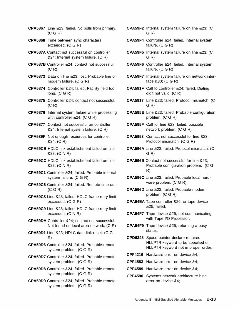
CPA5867 Line &23; failed. No polls from primary.(C G R)
CPA5868 Time between sync charactersexceeded. (C G R)
CPA587A Contact not successful on controller&24; Internal system failure. (C R)
CPA587B Controller &24; contact not successful.(C R)
CPA5873 Data on line &23; lost. Probable line ormodem failure. (C G R)
CPA5874 Controller &24; failed. Facility field toolong. (C G R)
CPA5875 Controller &24; contact not successful.(C R)
CPA5876 Internal system failure while processingwith controller &24; (C G R)
CPA5877 Contact not successful on controller&24; Internal system failure. (C R)
CPA589F Not enough resources for controller&24; (C R)
CPA59CB HDLC link establishment failed on line&23; (C N R)
CPA59CC HDLC link establishment failed on line&23; (C N R)
CPA59C1 Controller &24; failed. Probable internalsystem failure. (C G R)
CPA59C6 Controller &24; failed. Remote time-out.(C G R)
CPA59C8 Line &23; failed. HDLC frame retry limitexceeded. (C G R)
CPA59C9 Line &23; failed. HDLC frame retry limitexceeded. (C N R)
CPA59DA Controller &24; contact not successful.Not found on local area network. (C R)
CPA59D1 Line &23; HDLC data link reset. (C GR)
CPA59D6 Controller &24; failed. Probable remotesystem problem. (C G R)
CPA59D7 Controller &24; failed. Probable remotesystem problem. (C G R)
CPA59D8 Controller &24; failed. Probable remotesystem problem. (C G R)
CPA59D9 Controller &24; failed. Probable remotesystem problem. (C G R)
CPA59F2 Internal system failure on line &23; (CG R)
CPA59F4 Controller &24; failed. Internal systemfailure. (C G R)
CPA59F5 Internal system failure on line &23; (CG R)
CPA59F6 Controller &24; failed. Internal systemfailure. (C G R)
CPA59F7 Internal system failure on network inter-face &30; (C G R)
CPA591F Call to controller &24; failed. Dialingdigit not valid. (C R)
CPA5917 Line &23; failed. Protocol mismatch. (CG R)
CPA595E Line &23; failed. Probable configurationproblem. (C G R)
CPA595F Call for line &23; failed, possiblenetwork problem. (C G R)
CPA5953 Contact not successful for line &23;Protocol mismatch. (C G R)
CPA596A Line &23; failed. Protocol mismatch. (CG R)
CPA596B Contact not successful for line &23;Probable configuration problem. (C GR)
CPA596C Line &23; failed. Probable local hard-ware problem. (C G R)
CPA596D Line &23; failed. Probable modemproblem. (C G R)
CPA94EA Tape controller &26; or tape device&25; failed.
CPA94F7 Tape device &25; not communicatingwith Tape I/O Processor.
CPA94F9 Tape device &25; returning a busystatus.
CPD6348 Space pointer declare requiresHLLPTR keyword to be specified orHLLPTR keyword not in proper order.
CPF4216 Hardware error on device &4;
CPF4583 Hardware error on device &4;
CPF4589 Hardware error on device &4;
CPF4590 Systems network architecture binderror on device &4;
Appendix B. IBM-Supplied Alertable Messages B-13

CPF5201 Hardware failure on device &3;
CPF5247 Feedback code on device &4; notrecognized.
CPF5253 Device &4; sent too much data.
CPF5265 Hardware error on device &4;
CPF5266 Hardware error on device &4;
CPF5268 Hardware error on device &4;
CPF6772 Volume on device &1; cannot be proc-essed.
CPF6782 Device &25; not operational.
CPF6783 Device &25; is not ready.
CPF6784 Device &25; status changed from notready to ready.
CPF6786 Interface check on the device.
CPF6787 Equipment check while processing ondevice &25;
CPF6788 Media error found on volume &1; ondevice &25;
CPF6793 Write error on volume &1; on device&25;
CPF6794 End of media was found on device&25;
CPF6795 Load failure occurred on device &25;
CPF6796 Device &25; was reset.
CPF8BA8 Undesirable connection attempt on line&23,; adapter &40,; port &42;
CPF8B9A Line &23; in wrapped configuration atadapter &40;
CPIFFF8 Tape unit does not support synchro-nous data transfer
CPI0920 Error occurred on disk unit &1;
CPI0945 Mirrored protection is suspended ondisk unit &1;
CPI0956 Mirrored protection suspended on diskunit &1;
CPI0959 Mirrored protection suspended on diskunit &1;
CPI0970 Disk unit &1; not operating.
CPI0992 Errors occurred on disk unit &1;
CPI0996 Error occurred on disk unit &1;
CPI1136 Mirrored protection still suspended.
CPI1161 Unit &1; with device parity protectionnot fully operational.
CPI1167 Temporary I/O processor erroroccurred.
CPI2095 Changing primary language not com-plete
CPI2098 License information not processedduring installation.
CPI5818 Line &23; failed. Transmit completetimeout.
CPI59A2 Connection on device &25; failed.Internal system failure.
CPI59A4 Unacknowledged service on device&25; failed. Internal system failure.
CPI59B0 Internal system failure while settingthresholds for line &23;
CPI59CF Network interface &30; failed, channelerror occurred.
CPI59C7 Internal system failure while settingcounters for network interface &30;
CPI59C9 Internal system failure while settingcounters for line &23;
CPI59DF Network interface &30; failed, hardwareerror occurred.
CPI59D2 Unacknowledged service on device&25; was not successful.
CPI59E0 Network interface &30; failed, TEIassignment failed.
CPI59E1 Network interface &30; failed, TEIremoved.
CPI59E2 Line &23; failed, channel error onnetwork interface &30;
CPI59E3 Line &23; failed, hardware erroroccurred.
CPI59F2 Line &23; failed. Internal system failure.
CPI59F4 Controller &24; failed. Internal systemfailure.
CPI59F5 Line &23; failed. Internal system failure.
CPI59F6 Controller &24; failed. Internal systemfailure.
CPI59F7 Network interface &30; failed. Internalsystem failure.
B-14 OS/400 Alerts Support V4R1

CPI591B Device &25; on controller &24; failed.Internal system failure.
CPI591F Resources for controller &24; not suffi-cient.
CPI592B Resources not sufficient for line &23;
CPI592D Line &23; failed. Local DCE problem.
CPI593D Line &23; failed. Automatic recoverystarted.
CPI593E Controller &24; failed. Automaticrecovery started.
CPI5951 Network interface &30; failed. Auto-matic recovery started.
CPI7D10 Error on line &23; Unsolicited responsereceived.
CPI7E0A I/O Attachment Processor resource&26; failed.
CPI7E0B Attachment I/O Processor resource&26; failed.
CPI7E0C Attachment I/O Processor resource&26; failed.
CPI7E0D Resource &26; failed.
CPI7E0E Attachment I/O Processor resource&26; failed.
CPI7E0F Attachment I/O Processor resource&26; failed.
CPI7E00 Communications I/O processor &26;removed or failed.
CPI7E01 Communications I/O adapter &27;removed or failed.
CPI7E02 High Speed Communications Adapterresource &27; failed.
CPI7E03 Communications I/O adapter &27;removed or failed.
CPI7E04 Workstation controller &26; removed orfailed.
CPI7E05 High Speed Communications Adapterresource &27; failed.
CPI7E06 High Speed Communications Adapterresource &27; failed.
CPI7E07 High Speed Communications Adapterresource &27; failed.
CPI7E08 High Speed Communications Adapterresource &27; failed.
CPI7E09 High Speed Communications Adapterresource &27; failed.
CPI7E1B Cryptographic subsystem &26; failed
CPI7E1D Line &23; failed.
CPI7E1E Call failure. Active telephone line is notconnected to port &28;
CPI7E10 Attachment I/O Processor resource&26; failed.
CPI7E11 Distributed Data Interface resource&27; failed.
CPI7E12 Distributed Data Interface resource&26; failed.
CPI7E13 Distributed Data Interface resource&27; failed.
CPI7E14 Distributed Data Interface resource&27; failed.
CPI7E15 Distributed Data Interface resource&27; failed.
CPI7E18 Internal system error in fax adapter&26;
CPI7E19 Distributed Data Interface resource&27; failed.
CPI7E2A Cryptographic subsystem &26; failed
CPI7E2B Cryptographic subsystem &26; failed
CPI7E2C Cryptographic subsystem &26; failed
CPI7E2D Cryptographic subsystem &26; failed
CPI7E2E Cryptographic subsystem &26; failed
CPI7E20 Wrong command value sent by OS/400Licensed Program.
CPI7E21 Wrong command value sent by OS/400Licensed Program.
CPI7E22 Controller on line &23; failed.
CPI7E23 Invalid M/Q bit sequence on logicalchannel on line &23;
CPI7E24 Error on line &23; Internal systemfailure.
CPI7E25 Error on line &23; Internal systemfailure.
CPI7E26 Line &23; has entered a wrapped con-figuration
CPI7E28 Line &23; on adapter &27; hasswitched active connection fromprimary port to backup port
Appendix B. IBM-Supplied Alertable Messages B-15
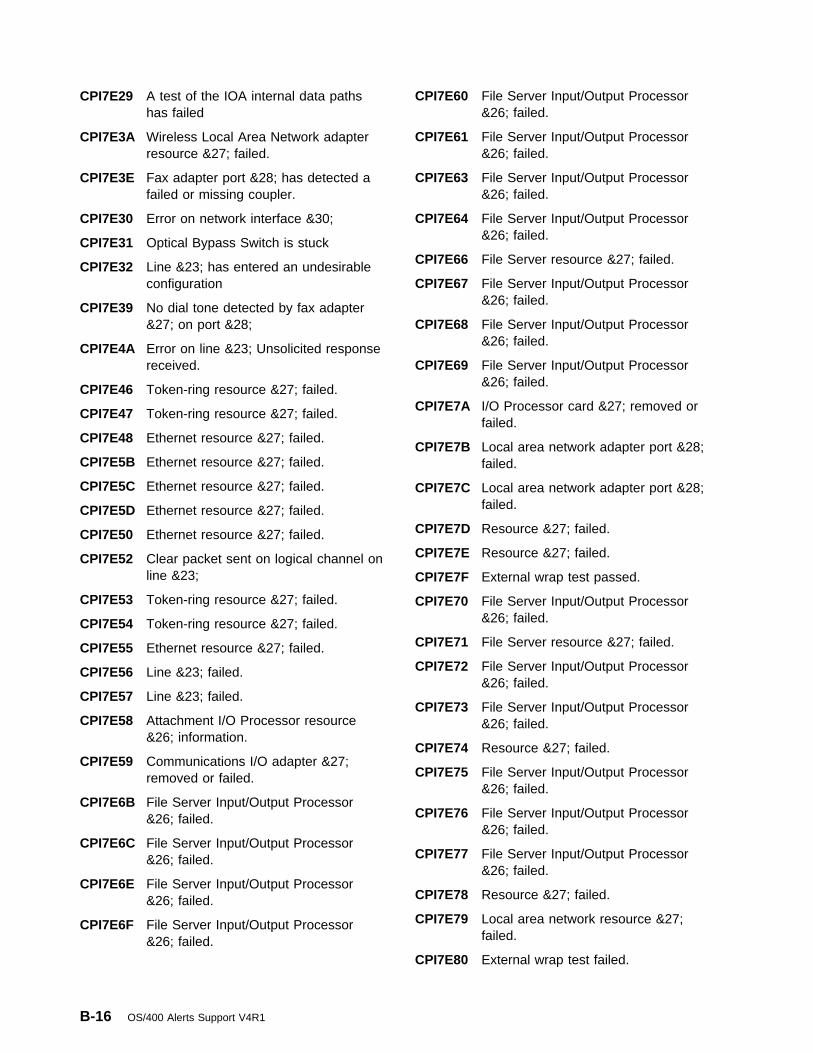
CPI7E29 A test of the IOA internal data pathshas failed
CPI7E3A Wireless Local Area Network adapterresource &27; failed.
CPI7E3E Fax adapter port &28; has detected afailed or missing coupler.
CPI7E30 Error on network interface &30;
CPI7E31 Optical Bypass Switch is stuck
CPI7E32 Line &23; has entered an undesirableconfiguration
CPI7E39 No dial tone detected by fax adapter&27; on port &28;
CPI7E4A Error on line &23; Unsolicited responsereceived.
CPI7E46 Token-ring resource &27; failed.
CPI7E47 Token-ring resource &27; failed.
CPI7E48 Ethernet resource &27; failed.
CPI7E5B Ethernet resource &27; failed.
CPI7E5C Ethernet resource &27; failed.
CPI7E5D Ethernet resource &27; failed.
CPI7E50 Ethernet resource &27; failed.
CPI7E52 Clear packet sent on logical channel online &23;
CPI7E53 Token-ring resource &27; failed.
CPI7E54 Token-ring resource &27; failed.
CPI7E55 Ethernet resource &27; failed.
CPI7E56 Line &23; failed.
CPI7E57 Line &23; failed.
CPI7E58 Attachment I/O Processor resource&26; information.
CPI7E59 Communications I/O adapter &27;removed or failed.
CPI7E6B File Server Input/Output Processor&26; failed.
CPI7E6C File Server Input/Output Processor&26; failed.
CPI7E6E File Server Input/Output Processor&26; failed.
CPI7E6F File Server Input/Output Processor&26; failed.
CPI7E60 File Server Input/Output Processor&26; failed.
CPI7E61 File Server Input/Output Processor&26; failed.
CPI7E63 File Server Input/Output Processor&26; failed.
CPI7E64 File Server Input/Output Processor&26; failed.
CPI7E66 File Server resource &27; failed.
CPI7E67 File Server Input/Output Processor&26; failed.
CPI7E68 File Server Input/Output Processor&26; failed.
CPI7E69 File Server Input/Output Processor&26; failed.
CPI7E7A I/O Processor card &27; removed orfailed.
CPI7E7B Local area network adapter port &28;failed.
CPI7E7C Local area network adapter port &28;failed.
CPI7E7D Resource &27; failed.
CPI7E7E Resource &27; failed.
CPI7E7F External wrap test passed.
CPI7E70 File Server Input/Output Processor&26; failed.
CPI7E71 File Server resource &27; failed.
CPI7E72 File Server Input/Output Processor&26; failed.
CPI7E73 File Server Input/Output Processor&26; failed.
CPI7E74 Resource &27; failed.
CPI7E75 File Server Input/Output Processor&26; failed.
CPI7E76 File Server Input/Output Processor&26; failed.
CPI7E77 File Server Input/Output Processor&26; failed.
CPI7E78 Resource &27; failed.
CPI7E79 Local area network resource &27;failed.
CPI7E80 External wrap test failed.
B-16 OS/400 Alerts Support V4R1

CPI7E81 Resource &27; failed.
CPI7E82 External wrap test failed.
CPI7FAA Line &23; failed, recovery stopped.
CPI7FA7 Resource &27; failed.
CPI7FA8 Resource &26; failed
CPI7FA9 Resource &27; failed.
CPI7FCB Insufficient resource to start communi-cations trace on network interface &30;
CPI7FCC Error on network interface &30; Internalsystem failure.
CPI7FCD Error on network interface &30; Internalsystem failure.
CPI7FCF Error on network interface &30; Internalsystem failure.
CPI7FDF Error on network interface &30; Internalsystem failure.
CPI7FD0 Line &23; on network interface &30;failed, recovery stopped. ISDN channelalready in use.
CPI7FD1 Error on line &23; attached to networkinterface &30; Adapter card notinstalled.
CPI7FD2 Error on line &23; attached to networkinterface &30; Internal system failure.
CPI7FD3 Error on line &23; attached to networkinterface &30; Internal system failure.
CPI7FD4 Error on line &23; attached to networkinterface &30; Internal system failure.
CPI7FD5 Error on line &23; attached to networkinterface &30; Internal system failure.
CPI7FD6 Error on line &23; attached to networkinterface &30; Internal system failure.
CPI7FD9 Error on line &23; attached to networkinterface &30; Internal system failure.
CPI7FED Network interface &30; failed. Internalsystem failure.
CPI7FEE Error on network interface &30; Internalsystem failure.
CPI7FEF Network interface &30; failed. Internalsystem failure.
CPI7FE0 Error on line &23; attached to networkinterface &30; Internal system failure.
CPI7FE1 Error on line &23; attached to networkinterface &30; Internal system failure.
CPI7FE2 Error on line &23; attached to networkinterface &30; Internal system failure.
CPI7FE3 Error on line &23; attached to networkinterface &30; Internal system failure.
CPI7FE5 Error on network interface &30; Internalsystem failure.
CPI7FE6 Error on network interface &30; Internalsystem failure.
CPI7FF2 Error on line &23; attached to networkinterface &30;
CPI7FF3 Error on &23; attached to networkinterface &30; Internal system failure.
CPI7F0D Lack of transmit buffers on networkinterface &30;
CPI7F0E Frame reject type X received onnetwork interface &30,; line &23;
CPI7F0F ISDN message received on networkinterface &30; was not correct.
CPI7F00 Error on network interface &30; Internalsystem failure.
CPI7F04 Controller &26; detected a non-recoverable bus error.
CPI7F06 Disconnect retry limit reached onnetwork interface &30;
CPI7F09 Frame reject type W received onnetwork interface &30,; line &23;
CPI7F1B Frame reject type Y received onnetwork interface &30,; line &23;
CPI7F1D Frame reject type Z, receive sequencecount error, received on network inter-face &30,; line &23;
CPI7F1E Error on network interface &30; Internalsystem failure.
CPI7F10 Invalid call reference value detected onnetwork interface &30;
CPI7F11 Error on network interface &30;
CPI7F13 No response from remote equipmenton network interface &30;
CPI7F14 Protocol message received with anunexpected cause code on networkinterface &30;
Appendix B. IBM-Supplied Alertable Messages B-17

CPI7F16 Error on network interface &30; Internalsystem failure.
CPI7F17 Error on network interface &30;
CPI7F18 Error on network interface &30; Internalsystem failure.
CPI7F19 Error on network interface &30; Internalsystem failure.
CPI7F2A Network interface &30; failed. Internalsystem failure.
CPI7F2B Error on network interface &30; duringget configuration request.
CPI7F2C I/O card Licensed Internal Code fornetwork interface &30; cannot start dueto lack of resource.
CPI7F2D Network interface &30; failed.
CPI7F2E Protocol message received with unex-pected or incorrect contents on networkinterface &30;
CPI7F2F Line &23; failed.
CPI7F20 Error on network interface &30; Internalsystem failure.
CPI7F21 Error on network interface &30; Internalsystem failure.
CPI7F25 Error on network interface &30; Internalsystem failure.
CPI7F26 Error on network interface &30; Internalsystem failure.
CPI7F27 Error on network interface &30; Internalsystem failure.
CPI7F28 Error on network interface &30; Internalsystem failure.
CPI7F29 Error on network interface &30; Internalsystem failure.
CPI7F3A Error on network interface &30; Internalsystem failure.
CPI7F3B Error on network interface &30; Internalsystem failure.
CPI7F3C Network interface &30; failed.
CPI7F3F Resource &27; failed.
CPI7F30 Error on network interface &30; I/Ocard Licensed Internal Code has endedabnormally
CPI7F37 Resource &27; failed.
CPI7F38 Resource &27; failed.
CPI7F39 Error on network interface &30; Internalsystem failure.
CPI7F4B Token ring resource &27; failed.
CPI7F4C Resource &27; failed.
CPI7F4E Error on line &23,; network interface&30; failed; insufficient resource.
CPI7F4F Error on network interface &30; Internalsystem failure.
CPI7F40 Error on line &23; attached to networkinterface &30; Internal system failure.
CPI7F42 Token-ring resource &27; failed.
CPI7F43 Resource &27; failed.
CPI7F48 Token-ring resource &27; failed.
CPI7F5A Error on line &23; attached to networkinterface &30; Internal system failure.
CPI7F5B Error on line &23; attached to networkinterface &30; Internal system failure.
CPI7F5C Error on line &23; attached to networkinterface &30; Internal system failure.
CPI7F5D Error on line &23; attached to networkinterface &30; Internal system failure.
CPI7F51 Error on line &23; attached to networkinterface &30; Internal system failure.
CPI7F55 Error on line &23; attached to networkinterface &30; Internal system failure.
CPI7F56 Error on line &23; attached to networkinterface &30; Internal system failure.
CPI7F6A Error on network interface &30; Internalsystem failure.
CPI7F6B Error on network interface &30; Internalsystem failure.
CPI7F6C Error on network interface &30; Internalsystem failure.
CPI7F6D Error on network interface &30; Internalsystem failure.
CPI7F6E Error on network interface &30; Internalsystem failure.
CPI7F60 Line &23; on network interface &30;failed. Internal system failure.
CPI7F61 Frame retry limit reached on networkinterface &30;
B-18 OS/400 Alerts Support V4R1

CPI7F62 Error on line &23; attached to networkinterface &30; Internal system failure.
CPI7F64 Resource &27; detected a non-recoverable bus error.
CPI7F65 Token-ring resource &26; failed.
CPI7F67 Error on network interface &30; Internalsystem failure.
CPI7F68 Error on line &23; attached to networkinterface &30; Internal system failure.
CPI7F7A Controller &26; failed.
CPI7F7B Error on network interface &30; InternalSystem Failure.
CPI7F7C Error on network interface &30;Received command field was notcorrect.
CPI7F7D Error on network interface &30; Aframe with an incorrect format orresponse was received.
CPI7F7E Error on network interface &30;
CPI7F7F Error on Network interface &30; Aframe with an oversized informationfield was received.
CPI7F70 Controller &26; failed.
CPI7F71 Controller &26; failed.
CPI7F72 Controller &26; failed.
CPI7F73 Controller &26; failed.
CPI7F74 Controller &27; failed.
CPI7F75 Controller &26; failed.
CPI7F76 Controller &26; failed.
CPI7F78 Controller &26; failed.
CPI7F8A Set-asynchronous-balance-mode-extended (SABME) frame received onnetwork interface &30;
CPI7F8D Receive CRC threshold limit reachedon network interface &30;
CPI7F80 Controller &26; failed.
CPI7F82 Controller &26; failed.
CPI7F9A Error on line &23; attached to networkinterface &30; Internal system failure.
CPI7F9C Receive CRC limit reached on line&23,; attached to network interface&30;
CPI7F90 Error on line &23; attached to networkinterface &30; Internal system failure.
CPI7F91 Error on network interface &30; Internalsystem failure.
CPI7F95 Network interface &30,; line &23; failed.Frame with incorrect command fieldreceived
CPI7F96 Frame with incorrect format orresponse received on line &23;attached to network interface &30;
CPI7F97 A frame with an incorrect count wasreceived on line &23; attached tonetwork interface &30;
CPI7F98 Frame with oversized information fieldreceived on line &23; attached tonetwork interface &30;
CPI7F99 Line &23; on network interface &30;failed, recovery stopped. Internalsystem failure.
CPI8EAA Line &23; failed
CPI8EAB Line &23; failed.
CPI8EAF Line &23; failed
CPI8EA5 Line &23; failed
CPI8EA6 Line &23; failed
CPI8EA7 Line &23; failed.
CPI8EA8 Line &23; failed
CPI8EC3 Device &25; failed, recovery stopped.
CPI8EC4 Device &25; failed, recovery stopped.
CPI8EC5 Device &25; failed.
CPI8EC6 Device &25; failed, recovery stopped.
CPI8EDB HDLC frame retry limit reached on line&23;
CPI8EEA Resource &27; failed.
CPI8EEB Line &23;
CPI8EE0 Error on port &28;
CPI8EE4 Resource &27; failed.
CPI8EE8 Resource &27; failed.
CPI8EE9 Resource &27; failed.
CPI8EFA Line &23; failed.
CPI8EFB Line &23; failed.
Appendix B. IBM-Supplied Alertable Messages B-19

CPI8EFC Port &28; status information. Line &23;is running.
CPI8EFE Port &28; status information. Line &23;is running.
CPI8EFF Line &23; failed because of configura-tion error.
CPI8EF0 Line &23; failed.
CPI8EF9 Line &23; failed.
CPI8E4F Line &23; status information, line isrunning.
CPI8E47 Error occurred on Line &23;
CPI8E48 Line &23; failed, recovery stopped.
CPI8E5A Line &23; failed.
CPI8E5C Line &23; failed.
CPI8E5E Line &23; error information.
CPI8E52 Port &28; failed to come up on line&23;
CPI8E53 Communication port &28; of line &26;is already being used.
CPI8E54 Communication port &28; of line &23;not installed.
CPI8E55 Line &23; failed, recovery stopped.
CPI8E56 Line &23; failed, recovery stopped.
CPI8E58 Line &23; error information.
CPI8E6A Line &23; error information.
CPI8E6B Error on line &23;
CPI8E6D Line &23; failed.
CPI8E6E Error on line &23;
CPI8E6F No cable was detected on communi-cation port &28; of line &23;
CPI8E67 Communication port &28; of networkinterface &30; not installed.
CPI8E68 An error occurred on line &23;
CPI8E69 Line &23; failed.
CPI8E7B Error on line &23;; connection clearedby network equipment.
CPI8E7C Line &23; failed, recovery stopped.
CPI8E7D Line &23; failed, token-ring line is nolonger connected to the ring.
CPI8E7F Line &23; failed during connection tothe token-ring network.
CPI8E8A Line &23; failed during insertion intothe token-ring network
CPI8E8D Line &23; failed.
CPI8E8E Line &23; failed.
CPI8E8F Line &23; failed.
CPI8E86 Network interface &30; failed.
CPI8E87 Network interface &30; error informa-tion.
CPI8E89 Line &23; failed during insertion intothe token-ring network.
CPI8E9B Error on network interface &30;
CPI8E90 Line &23; failed during insertion intothe token-ring network.
CPI8E91 Line &23; failed.
CPI8E92 Line &23; failed during insertion intothe token-ring network.
CPI8E98 Line &23; failed.
CPI8FA1 Line &23; failed.
CPI8FA2 Line &23; failed.
CPI8FA5 Line &23; failed.
CPI8FA7 Line &23; failed.
CPI8FA8 Line &23; failed.
CPI8FA9 Line &23; failed.
CPI8FBA Resource &27; failed.
CPI8FBF Token-ring resource &27; failed.
CPI8FB1 Line &23; failed.
CPI8FB8 Token-ring resource &27; failed.
CPI8FCA Line &23; failed during insertion intothe token-ring network.
CPI8FCB Line &23; failed during insertion intothe token-ring network.
CPI8FCC Line &23; failed during insertion intothe token-ring network.
CPI8FCD Line &23; failed during insertion intothe token-ring network.
CPI8FCE Line &23; failed.
CPI8FC0 Line &23; failed.
CPI8FC1 DSR signal connection failed.
CPI8FC2 Line &23; failed.
CPI8FC3 Line &23; failed.
B-20 OS/400 Alerts Support V4R1

CPI8FC9 X.25 Network Layer Protocol ErrorDetected on line &23;
CPI8FD1 Line &23; failed.
CPI8FED Port &28; status information. Line &23;is running.
CPI8FFA Line &23; threshold information.
CPI8FFD Ethernet resource &27; failed.
CPI8FFE Ethernet resource &26; failed.
CPI8FF0 Call cannot be received for line &23;No connections available.
CPI8FF1 Line &23; cannot be varied on due tolack of IOP resources
CPI8F0A Resource &26; failed.
CPI8F0B Resource &26; failed.
CPI8F0C Resource &27; failed.
CPI8F0E Resource &26; failed.
CPI8F0F DCE on network interface &30; notready.
CPI8F00 Resource &27; failed.
CPI8F02 Resource &27; failed.
CPI8F03 Resource &26; failed.
CPI8F04 Resource &26; failed.
CPI8F05 Resource &26; failed.
CPI8F06 Resource &26; failed.
CPI8F07 Resource &26; failed.
CPI8F08 Resource &26; failed.
CPI8F09 Resource &26; failed.
CPI8F1A Error on line &23;
CPI8F1B Network interface &30; failed.
CPI8F1C Error on communication port name&28;
CPI8F1D Probable local hardware failure onnetwork interface &30;
CPI8F1E Probable local hardware failure onnetwork interface &30;
CPI8F1F Line &23; failed.
CPI8F10 Resource &27; failed.
CPI8F11 Resource &27; failed.
CPI8F12 Resource &27; failed.
CPI8F13 Line &23; failed.
CPI8F14 Line &23; failed.
CPI8F15 Line &23; failed.
CPI8F17 Line &23; failed.
CPI8F18 Error on Port &28;
CPI8F19 Error on port &28;
CPI8F2A Line &23; failed.
CPI8F2B Line &23; failed.
CPI8F20 Line &23; failed.
CPI8F21 Line &23; failed.
CPI8F22 Line &23; failed.
CPI8F23 Line &23; failed.
CPI8F24 Line &23; failed.
CPI8F25 Line &23; failed.
CPI8F26 Line &23; failed.
CPI8F29 Line &23; failed.
CPI8F3A Line &23; threshold information.
CPI8F3B Port &28; status information. Line &23;is running.
CPI8F3D Network time-out type 1 occurred onPort &28; Line &23; is running.
CPI8F3E Network time-out type 2 occurred onPort &28; Line &23; is running.
CPI8F3F Network time-out type 3A occurred onPort &28; Line &23; is running.
CPI8F30 Line &23; failed.
CPI8F31 Line &23; failed.
CPI8F32 Line &23; failed.
CPI8F34 Line &23; status information, line isrunning.
CPI8F35 Line &23; failed.
CPI8F36 Line &23; failed.
CPI8F39 Line &23; failed.
CPI8F40 Line &23; failed.
CPI8F42 Line &23; failed.
CPI8F43 Line &23; failed.
CPI8F44 Line &23; failed.
CPI8F46 Line &23; failed.
Appendix B. IBM-Supplied Alertable Messages B-21

CPI8F5A Line &23; failed.
CPI8F5B Line &23; failed.
CPI8F5E No cable was detected on port &28; ofnetwork interface &30;
CPI8F52 Line &23; threshold information.
CPI8F6A Line &23; failed.
CPI8F6E Line &23; failed, token-ring line is nolonger connected to the ring.
CPI8F6F Line &23; failed, token-ring line nolonger connected to the ring.
CPI8F61 Line &23; failed.
CPI8F62 Line &23; failed.
CPI8F65 Line &23; failed.
CPI8F7A Line &23; failed, recovery stopped.
CPI8F7B Line &23; failed.
CPI8F7C Line &23; failed.
CPI8F7D Network time-out type 3B on Port &28;Line &23; running.
CPI8F71 Network call-progress-signal type 23 onport &28; Line &23; running.
CPI8F73 Line &23; failed.
CPI8F79 Line &23; failed.
CPI8F80 Line &23; failed.
CPI8F81 Line &23; failed.
CPI8F82 A network time-out type 7 occurred online &23;
CPI8F83 An error occurred on Line &23;
CPI8F84 A network time-out type 6 occurred online &23;
CPI8F85 Line &23; failed.
CPI8F86 Line &23; failed.
CPI8F87 Line &23; error information.
CPI8F88 Line &23; failed.
CPI8F9A Network interface &30; failed.
CPI8F9B Network interface &30; failed.
CPI8F9C Network not active on network interface&30;
CPI8F92 Line &23; failed.
CPI8F94 Line &23; failed.
CPI8F98 Error on port &28;
CPI8F99 Error on line &23;
CPI889A I/O Optical Bus failure is detected.
CPI889C Processor cannot communicate withSystem Unit Expansion unit.
CPI889D Optical bus cable is connected incor-rectly.
CPI8890 Failure during an operation with I/Oprocessor.
CPI8891 I/O processor with resource name &26;is not operational.
CPI8892 I/O Bus Failure during operation withI/O processor.
CPI8893 The I/O Bus Encountered no IOPsDuring IPL.
CPI8897 Processor cannot communicate withbus extension unit
CPI8898 Optical signal loss is detected onoptical bus.
CPI9340 Error with work station adapter &24;
CPI9341 A LIC error occurred on work stationadapter &24;
CPI9342 Too many devices attached to workstation adapter &24;
CPI9350 Error with device &25; on work stationcontroller &24;
CPI9351 Error with device &25; on work stationcontroller &24;
CPI9352 Error with device &25; on work stationcontroller &24;
CPI9353 Too many devices attached to workstation controller &24;
CPI9354 Error with work station controller &24;
CPI9355 A Licensed Internal Code erroroccurred on work station controller.
CPI9356 Error with magnetic stripe reader ondevice &25;
CPI9357 Error with magnetic stripe reader orselector light pen on device &25;
CPI9358 Too many devices varied on to workstation controller &24;
CPI9359 Device configuration error occurred onwork station controller &24;
B-22 OS/400 Alerts Support V4R1
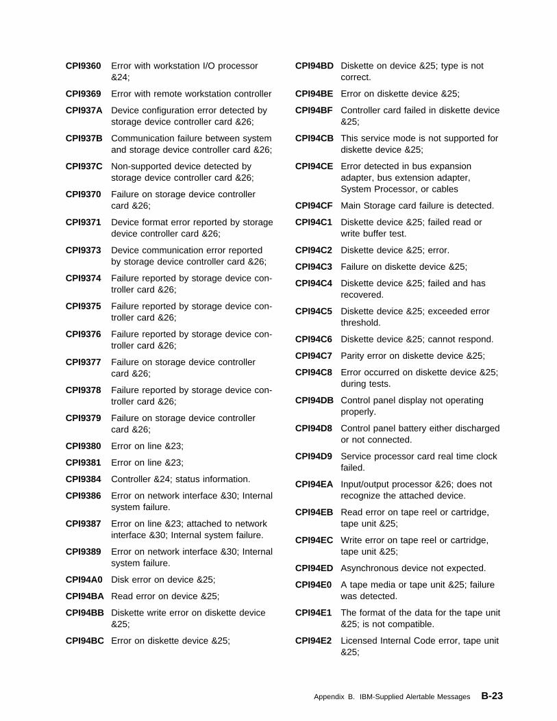
CPI9360 Error with workstation I/O processor&24;
CPI9369 Error with remote workstation controller
CPI937A Device configuration error detected bystorage device controller card &26;
CPI937B Communication failure between systemand storage device controller card &26;
CPI937C Non-supported device detected bystorage device controller card &26;
CPI9370 Failure on storage device controllercard &26;
CPI9371 Device format error reported by storagedevice controller card &26;
CPI9373 Device communication error reportedby storage device controller card &26;
CPI9374 Failure reported by storage device con-troller card &26;
CPI9375 Failure reported by storage device con-troller card &26;
CPI9376 Failure reported by storage device con-troller card &26;
CPI9377 Failure on storage device controllercard &26;
CPI9378 Failure reported by storage device con-troller card &26;
CPI9379 Failure on storage device controllercard &26;
CPI9380 Error on line &23;
CPI9381 Error on line &23;
CPI9384 Controller &24; status information.
CPI9386 Error on network interface &30; Internalsystem failure.
CPI9387 Error on line &23; attached to networkinterface &30; Internal system failure.
CPI9389 Error on network interface &30; Internalsystem failure.
CPI94A0 Disk error on device &25;
CPI94BA Read error on device &25;
CPI94BB Diskette write error on diskette device&25;
CPI94BC Error on diskette device &25;
CPI94BD Diskette on device &25; type is notcorrect.
CPI94BE Error on diskette device &25;
CPI94BF Controller card failed in diskette device&25;
CPI94CB This service mode is not supported fordiskette device &25;
CPI94CE Error detected in bus expansionadapter, bus extension adapter,System Processor, or cables
CPI94CF Main Storage card failure is detected.
CPI94C1 Diskette device &25; failed read orwrite buffer test.
CPI94C2 Diskette device &25; error.
CPI94C3 Failure on diskette device &25;
CPI94C4 Diskette device &25; failed and hasrecovered.
CPI94C5 Diskette device &25; exceeded errorthreshold.
CPI94C6 Diskette device &25; cannot respond.
CPI94C7 Parity error on diskette device &25;
CPI94C8 Error occurred on diskette device &25;during tests.
CPI94DB Control panel display not operatingproperly.
CPI94D8 Control panel battery either dischargedor not connected.
CPI94D9 Service processor card real time clockfailed.
CPI94EA Input/output processor &26; does notrecognize the attached device.
CPI94EB Read error on tape reel or cartridge,tape unit &25;
CPI94EC Write error on tape reel or cartridge,tape unit &25;
CPI94ED Asynchronous device not expected.
CPI94E0 A tape media or tape unit &25; failurewas detected.
CPI94E1 The format of the data for the tape unit&25; is not compatible.
CPI94E2 Licensed Internal Code error, tape unit&25;
Appendix B. IBM-Supplied Alertable Messages B-23

CPI94E3 Tape unit &25; failed.
CPI94E4 Tape unit &25; received incorrectcommand or command parameter.
CPI94E6 User detected a diskette unit &25;problem.
CPI94E8 Input/output processor &26; failed.
CPI94E9 Licensed Internal Code error, I/Oprocessor resource &26;
CPI94FA Tape I/O Processor &26; detected nonsupported device configuration.
CPI94FC Disk error on device &28;
CPI94F0 Either tape controller &26; or tape unit&25; failed.
CPI94F2 Tape I/O Processor &26; failed.
CPI94F5 Either Tape I/O Processor &26; or tapedevice &25; failed.
CPI94F6 Tape I/O Processor &26; programfailed.
CPI94F8 Tape I/O Processor &26,; tape device&25,; or S/370 interface failure.
CPI9400 Controller &26; failed.
CPI9401 Controller &26; indicates control panelproblem.
CPI9402 Controller &26; indicates adapter &27;error.
CPI9403 Controller &26; indicates error on tapeor disk unit.
CPI9404 Controller &26; indicates error ondiskette unit &28;
CPI9405 Controller &26; failed.
CPI9406 Error on tape reel or cartridge, tapeunit &25;
CPI9407 Controller &26; indicates error ondevice &28;
CPI9408 I/O processor &26; error log full.
CPI946A Interface error: Tape unit &25;(resource &28); or IOP &26;
CPI946B IOP resource &26; recovered from tem-porary error.
CPI947A Disk motor problem.
CPI947B Data decompression hardware failureon IOP &26; IOP &26; is still opera-tional.
CPI947C Time-of-Day function has failed on IOP&26,; IOP &26; is operational
CPI947D IOP &26; indicates adapter &27; error.
CPI947E Data compression hardware failure onIOP &26; IOP &26; is still operational.
CPI947F IOP &26; failed.
CPI9470 I/O processor &26; failed.
CPI9471 A lack of resources was detected onI/O processor &26;
CPI9472 Partial I/O processor &26; failureoccurred.
CPI9475 Partial I/O processor &26; failureoccurred.
CPI9476 Temporary Device Error.
CPI9477 Disk subsystem configuration error.
CPI9478 Disk command timeout error.
CPI9479 Disk Media Error.
CPI9485 Address switch setting changed ontape device &25;
CPI9486 Address switch failed on tape device&25;
CPI9487 Error on tape device &25;
CPI9488 Error when power turned on to tapedevice &25;
CPI9489 Error while loading tape on tape device&25;
CPI9490 Disk error on device &28;
CPI95A3 Optical Library &25; I/O station failure.
CPI95A6 Optical Library &25; storage slot failure.
CPI95A8 Optical Library &25; optical drivefailure.
CPI95BA Optical Library &25; optical drive writefailure.
CPI95B0 Optical Library &25; optical drive readfailure.
CPI95B1 Access panel open on Optical Library&25;
CPI95B3 Optical Library &25; SCSI bus error.
CPI95B7 Optical Library &25; optical drivefailure.
B-24 OS/400 Alerts Support V4R1

CPI95B8 Optical Library &25; optical drivefailure.
CPI95B9 Optical Library &25; media or drivefailure.
CPI95CB Optical Library &25; optical drivefailure.
CPI95CD Optical Library &25; media error.
CPI95C8 Optical Library &25; device error.
CPI95DB Optical Library &25; IOP LIC failure.
CPI95DD Optical Library &25; found an opticaldrive which is not supported.
CPI95D0 Optical Library &25; drive status notvalid
CPI95D1 Optical Library &25; SCSI bus error.
CPI95D3 Optical Library &25; internal failure.
CPI95D5 Optical Library &25; failed to respond.
CPI95E4 Optical Library &25; internal disk unitfailed.
CPI9502 Tape Unit &25; lost power before end-of-tape processing completed
CPI958A Optical Library &25; data cartridgecould not be moved.
CPI958D Optical Library &25; data cartridgecould not be moved.
CPI9580 Optical Library &25; error occurred.
CPI9581 Optical Library &25; did not becomeready.
CPI9582 Optical Library &25; data cartridgecould not be moved.
CPI9583 Optical Library &25; autochangerfailure.
CPI9584 Optical Library &25; autochangerfailure.
CPI9586 Optical Library &25; power supplyerror.
CPI9587 Optical Library &25; power supplyerror.
CPI9588 Optical Library &25; optical drive notresponding.
QCPFMSG Messages withALROPT(*UNATTEND)
CPA2C64 File &1; was not found on device &2;(C R)
CPA2601 Device &25; failed. Recovery ended. (CG R)
CPA2602 Device &25; failed. Recovery ended. (CG R)
CPA2603 Device &25; could not establish ses-sions. Recovery ended. (C G R)
CPA3701 Compression not available on alldevices. (C I)
CPA3704 Load tape containing library &1; ondevice &2; (C G)
CPA3705 Load previous tape volume on device&2; (C G)
CPA3706 Load next tape volume on device &2;(C G)
CPA3707 Load correct tape volume on device&2; (C G)
CPA400A Volume &5; density is not correct. (C RINZ)
CPA400C File label &4; with creation date &5;already exists on diskette in &3; (C R)
CPA400D ASCII code of volume &5; on device&4; is not valid (C R).
CPA400E ASCII code of volume &5; on device&4; is not valid (C INZ R).
CPA400F Media error while writing to volume &5;on device &4; (C G)
CPA4001 End of forms on printer &3; (C I)
CPA4002 Verify alignment on printer &3; (I G NR E C)
CPA4003 Form feed attachment &4; required onprinter &3; (C G H)
CPA4004 End of ribbon on printer &3; (C H IPAGE 1-9999999)
CPA4005 End of ribbon on printer &3; (C I)
CPA4006 Volume &5; density is not correct. (CR)
CPA4007 Paper jam on printer &3; (C R)
CPA4008 Open cover on printer &3; (C H PAGE1-9999999)
CPA4009 Open cover on printer &3; (C R)
CPA401A Volume &5; is not usable. (C R)
Appendix B. IBM-Supplied Alertable Messages B-25

CPA401B Volume on device &4; at end of data.(C G)
CPA4010 Character on printer &3; not printable.(H I PAGE 1-9999999)
CPA4011 Character on printer &3; not printable.(C R)
CPA4012 Print check on printer &3; (C H PAGE1-9999999)
CPA4013 Print check on printer &3; (C R)
CPA4014 Forms error on printer &3; (C H PAGE1-9999999)
CPA4015 Forms check on printer &3; (C R)
CPA4016 End of forms on printer &3; (C H IPAGE 1-9999999)
CPA4017 End of forms on printer &3; (C I)
CPA4018 Operator action required on device &1;
CPA4019 Paper jam on printer &3; (C H PAGE1-9999999)
CPA4020 Volume &5; not last volume for file &6;(C I R).
CPA4021 Load failure occurred on device &4; (CR)
CPA4022 Error while reading labels on device&3; (C R)
CPA4023 Volume &4; damaged for file sequence&5; (C R)
CPA4024 Volume &5; density differs from othervolumes (C R INZ).
CPA4025 Diskette in &1; different from firstdiskette in multivolume file. (C R INZ)
CPA4026 Diskette in device &2; not preparedcorrectly. (C R INZ)
CPA4027 Code on volume &5; differs from pre-vious volumes (C R).
CPA4028 Diskette in device &2; not written in &4;(C R INZ)
CPA4029 Diskette in &3; has wrong format forsave or restore. (C R INZ)
CPA403E Tape management information notavailable. (C I R)
CPA403F Storage extension information notavailable. (I R)
CPA4030 Volume identifier not standard for file&2; in library &3; on device &4; (C I R)
CPA4031 Expected volume &6,; found volume&5; in device &3; (C I R INZ)
CPA4032 Volume table of contents (VTOC) readerror on device &3; (C R INZ)
CPA4033 Diskette volume identifier &2; at device&1; not valid for save or restore. (C IR)
CPA4034 Volume &5; not first for file sequencenumber &6; (C I R).
CPA4035 Labels on volume &5; device &4; arenot valid (C R).
CPA4036 File expiration dates out of sequence(C I R).
CPA4037 Character &5; on printer &3; not print-able. (H I PAGE 1-9999999)
CPA4038 Character &5; on printer &3; not print-able. (C R)
CPA4039 End of forms on printer &3; (C H IPAGE 1-9999999)
CPA4040 End of forms on printer &3; (C I)
CPA4041 Problem on device &1; requires oper-ator help.
CPA4042 Print head overheating on printer &3;(C H I PAGE 1-9999999)
CPA4043 Print head overheating on printer &3;(C R)
CPA4044 Verify alignment on printer &3; (I C GR)
CPA4045 Diskette volume identifier &2; in device&1; not valid for save or restore. (C RINZ)
CPA4046 Print check on printer &3; (C H I PAGE1-9999999)
CPA4047 Either end of forms or forms check onprinter &3; (C H I PAGE 1-9999999)
CPA4048 End of forms or forms check on printer&3; (C I)
CPA4049 Error on diskette volume &6; device&1; (C R)
CPA4050 Not authorized to data on diskette indevice &1; volume &2; (C R)
B-26 OS/400 Alerts Support V4R1

CPA4051 Not authorized to data on diskette indevice &1; volume &2; (C R INZ)
CPA4052 Diskette in device &2; out of sequence.(C R)
CPA4053 One-sided diskette required in device&1; (C R)
CPA4054 Error while reading labels on device&3; (C R INZ)
CPA4055 No authority to access data (C INZ R).
CPA4056 Code on volume &5; differs from pre-vious volumes (C INZ R).
CPA4057 Labels on volume &5; device &4; arenot valid (C INZ R).
CPA4058 Volume &5; on device &4; wrong type(C INZ R).
CPA4059 Found &5;; expected &6; on device &4;(C I INZ R)
CPA4060 Device &4; cannot process loadedvolume. (C R INZ)
CPA4061 Cannot initialize tape on device &4; (CR)
CPA4063 Cannot access data file on volume &5;device &4; (C INZ R).
CPA4064 Diskette in &1; did not format correctly.(C R INZ)
CPA4065 Check status lights on printer &3; (C HPAGE 1-9999999)
CPA4066 Check status lights on printer &3; (C R)
CPA4068 Volume &5; density differs from pre-vious volumes. (C R)
CPA407A Paper size changed on printer &3; (C HPAGE 1-99999)
CPA4070 Diskette in device &1; has extendedlabel area. (C R)
CPA4071 Platen protection tape on device &2;needs replacement. (I C)
CPA4073 Data position check on printer &3; (C HPAGE 1-9999999)
CPA4074 Data position check on printer &3; (CR)
CPA4075 Not enough storage on printer &3; (C HPAGE 1-9999999)
CPA4076 Not enough storage on printer &3; (CG)
CPA4077 Load form type '&2'; on printer &3; (I CG)
CPA4078 Paper length error on printer &3; (C HPAGE 1-9999999)
CPA4081 File &7; will be written over. (C I R)
CPA4082 Diskette in device &1; is write-protected. (C R)
CPA4085 Insert next diskette to receive a copy.(C G)
CPA4086 Device &4; was not ready or nextvolume was not loaded. (C R)
CPA4087 Diskette inserted in device &3; is notcorrect. (C R)
CPA4088 Load next tape volume on device &4;(C G)
CPA4089 Load volume &5; on device &4; (C G)
CPA4090 Device &4; was not ready. (C R)
CPA4091 Wrong cartridge type in device &4; (CR).
CPA4114 File &6; not found on volume &5;device &4; (C R).
CPA4124 Found &5;; expected &6; on device &4;(C R)
CPA4134 Cannot access data on volume &5;device &4; (C R).
CPA4158 Volume &5; on device &4; wrong type(C R).
CPA4240 No authority to access data file onvolume &5; (C R).
CPA4251 Change LPI switch on printer &1; to&2; (C G)
CPA4252 Diskette device &3; not ready. (C R)
CPA4253 Extensive error recovery is occurringon diskette in device &1; (C I)
CPA4254 &4; LPI not allowed on printer &3; (CG)
CPA4257 Creation date of file label &4; notmatching. (C I)
CPA4258 File label &4; already exists on diskettein &3; (C R)
Appendix B. IBM-Supplied Alertable Messages B-27
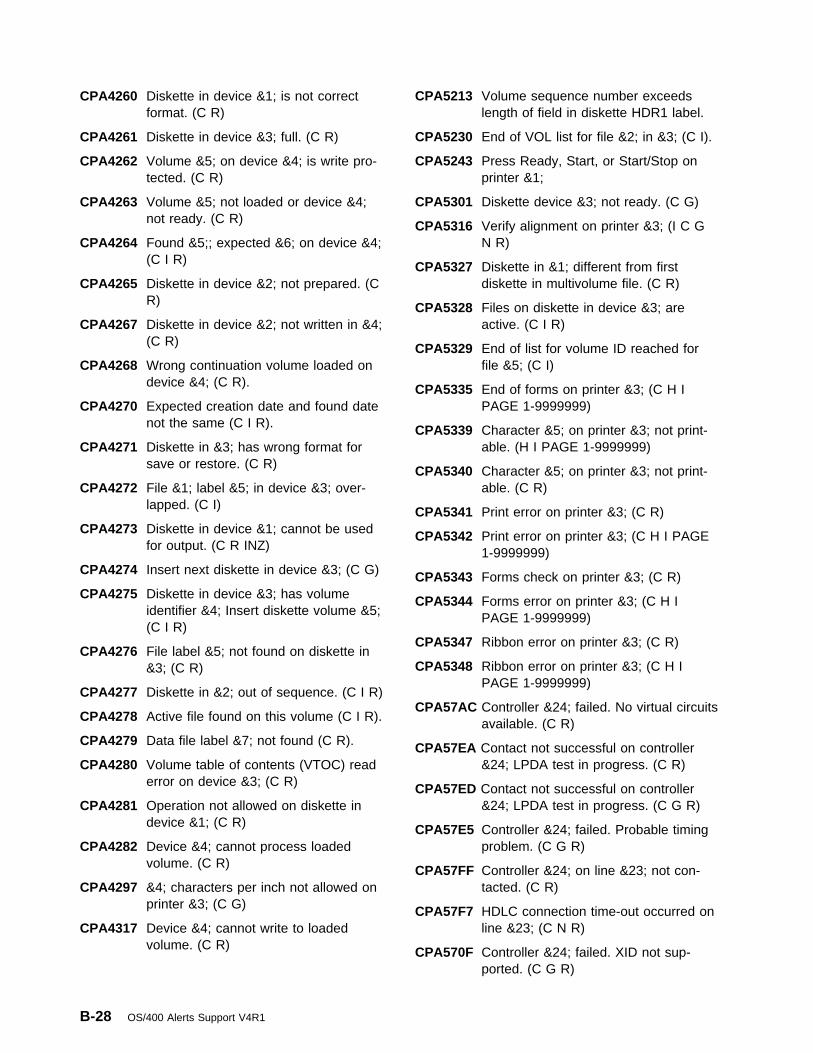
CPA4260 Diskette in device &1; is not correctformat. (C R)
CPA4261 Diskette in device &3; full. (C R)
CPA4262 Volume &5; on device &4; is write pro-tected. (C R)
CPA4263 Volume &5; not loaded or device &4;not ready. (C R)
CPA4264 Found &5;; expected &6; on device &4;(C I R)
CPA4265 Diskette in device &2; not prepared. (CR)
CPA4267 Diskette in device &2; not written in &4;(C R)
CPA4268 Wrong continuation volume loaded ondevice &4; (C R).
CPA4270 Expected creation date and found datenot the same (C I R).
CPA4271 Diskette in &3; has wrong format forsave or restore. (C R)
CPA4272 File &1; label &5; in device &3; over-lapped. (C I)
CPA4273 Diskette in device &1; cannot be usedfor output. (C R INZ)
CPA4274 Insert next diskette in device &3; (C G)
CPA4275 Diskette in device &3; has volumeidentifier &4; Insert diskette volume &5;(C I R)
CPA4276 File label &5; not found on diskette in&3; (C R)
CPA4277 Diskette in &2; out of sequence. (C I R)
CPA4278 Active file found on this volume (C I R).
CPA4279 Data file label &7; not found (C R).
CPA4280 Volume table of contents (VTOC) readerror on device &3; (C R)
CPA4281 Operation not allowed on diskette indevice &1; (C R)
CPA4282 Device &4; cannot process loadedvolume. (C R)
CPA4297 &4; characters per inch not allowed onprinter &3; (C G)
CPA4317 Device &4; cannot write to loadedvolume. (C R)
CPA5213 Volume sequence number exceedslength of field in diskette HDR1 label.
CPA5230 End of VOL list for file &2; in &3; (C I).
CPA5243 Press Ready, Start, or Start/Stop onprinter &1;
CPA5301 Diskette device &3; not ready. (C G)
CPA5316 Verify alignment on printer &3; (I C GN R)
CPA5327 Diskette in &1; different from firstdiskette in multivolume file. (C R)
CPA5328 Files on diskette in device &3; areactive. (C I R)
CPA5329 End of list for volume ID reached forfile &5; (C I)
CPA5335 End of forms on printer &3; (C H IPAGE 1-9999999)
CPA5339 Character &5; on printer &3; not print-able. (H I PAGE 1-9999999)
CPA5340 Character &5; on printer &3; not print-able. (C R)
CPA5341 Print error on printer &3; (C R)
CPA5342 Print error on printer &3; (C H I PAGE1-9999999)
CPA5343 Forms check on printer &3; (C R)
CPA5344 Forms error on printer &3; (C H IPAGE 1-9999999)
CPA5347 Ribbon error on printer &3; (C R)
CPA5348 Ribbon error on printer &3; (C H IPAGE 1-9999999)
CPA57AC Controller &24; failed. No virtual circuitsavailable. (C R)
CPA57EA Contact not successful on controller&24; LPDA test in progress. (C R)
CPA57ED Contact not successful on controller&24; LPDA test in progress. (C G R)
CPA57E5 Controller &24; failed. Probable timingproblem. (C G R)
CPA57FF Controller &24; on line &23; not con-tacted. (C R)
CPA57F7 HDLC connection time-out occurred online &23; (C N R)
CPA570F Controller &24; failed. XID not sup-ported. (C G R)
B-28 OS/400 Alerts Support V4R1

CPA571A Controller &24; on line &23; not con-tacted. XID retry limit reached. (C R)
CPA571B Controller &24; on line &23; not con-tacted. XID retry limit reached. (C G R)
CPA571C Controller &24; on line &23; not con-tacted. Probable configuration problem.(C G R)
CPA571E Controller &24; on line &23; not con-tacted. Probable configuration problem.(C R)
CPA571F Controller &24; on line &23; not con-tacted. Probable configuration problem.(C G R)
CPA5714 System cannot call controller &24; Nolines available. (C R)
CPA5719 Controller &24; not contacted. Config-uration problem. (C R)
CPA572A Controller &24; not contacted. Probableremote system problem. (C R)
CPA572B Controller &24; not contacted. Probableremote system problem. (C G R)
CPA572C Controller &24; not contacted. Probableconfiguration problem. (C R)
CPA572D Controller &24; not contacted. Probableconfiguration problem. (C G R)
CPA572E Controller &24; on line &23; not con-tacted. Protocol error. (C R)
CPA572F Controller &24; on line &23; not con-tacted. Protocol error. (C G R)
CPA5722 System cannot call out on line &23;Connection list entry is *ANY for theremote number (C N R).
CPA5723 System cannot call out on line &23;Connection list entry error. (C N R)
CPA5724 System cannot call controller &24; Nolines available. (C R)
CPA5725 System cannot call out on line &23; Nonetwork interfaces available. (C N R)
CPA5726 System cannot call out on line &23;Connection list &40; does not exist. (CN R)
CPA5727 System cannot call out on line &23;Unable to use connection list &40; (CN R)
CPA5728 System cannot call out on line &23;Connection list entry &41; not found. (CN R)
CPA5729 System cannot call out on line &23;Line unusable at this time. (C N R)
CPA573A Controller &24; on line &23; not con-tacted. Probable application programproblem. (C R)
CPA573B Controller &24; on line &23; not con-tacted. Probable configuration problem.(C R)
CPA573D Controller &24; on line &23; not con-tacted. Local configuration problem. (CR)
CPA5732 Call on controller &24; failed. Con-nection list entry is *ANY for theremote number. (C R)
CPA5733 System cannot call out on controller&24; Connection list entry error. (C R)
CPA5734 System cannot call out on controller&24; Unable to use connection list &40;(C R)
CPA5735 System cannot call out on controller&24; Unable to use connection list &40;(C R)
CPA5736 System cannot call out on controller&24; Connection list entry &41; notfound. (C R)
CPA5737 Controller &24; on line &23; not con-tacted. Probable configuration problem.(C R)
CPA5738 Controller &24; on line &23; not con-tacted. Probable configuration problem.(C G R)
CPA5739 Controller &24; on line &23; not con-tacted. Local configuration problem. (CR)
CPA574A Controller &24; on line &23; not con-tacted. Probable configuration problem.(C R)
CPA574B Controller &24; on line &23; not con-tacted. Probable configuration problem.(C G R)
CPA574C Controller &24; on line &23; not con-tacted. (C R)
Appendix B. IBM-Supplied Alertable Messages B-29
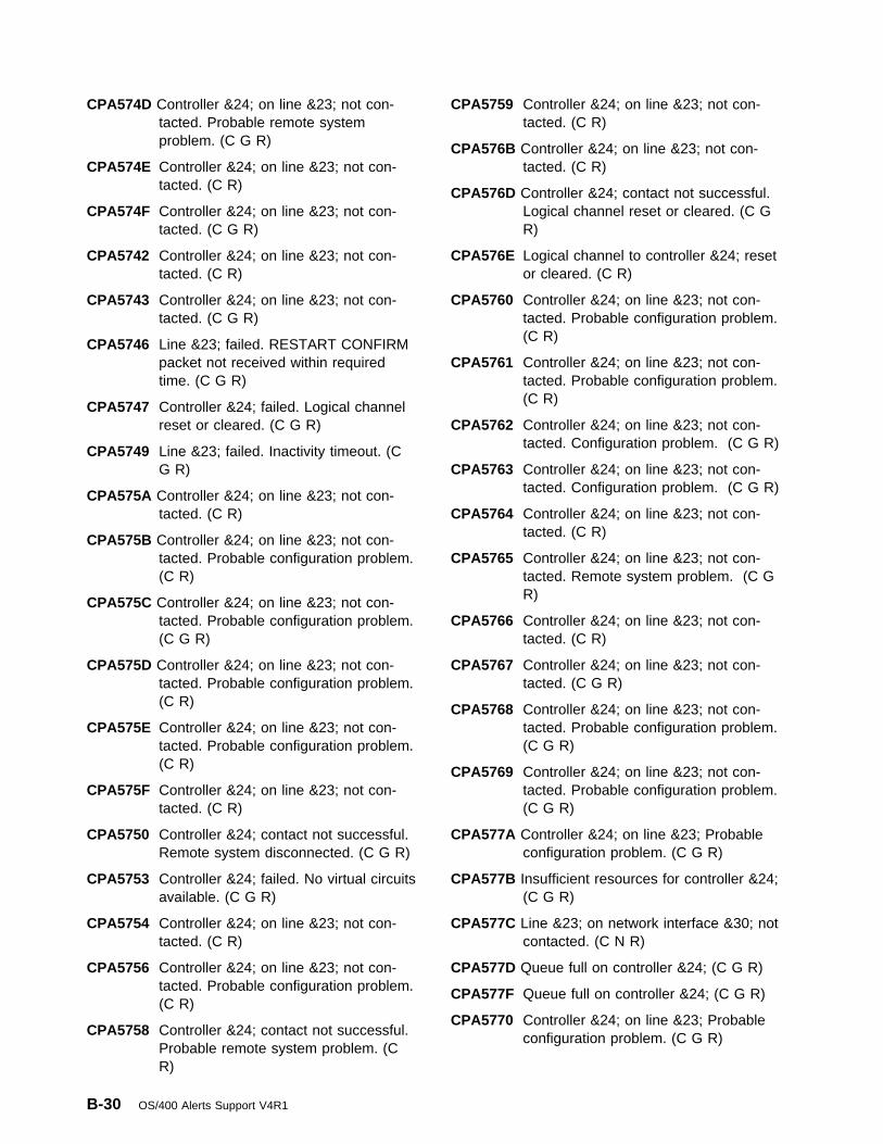
CPA574D Controller &24; on line &23; not con-tacted. Probable remote systemproblem. (C G R)
CPA574E Controller &24; on line &23; not con-tacted. (C R)
CPA574F Controller &24; on line &23; not con-tacted. (C G R)
CPA5742 Controller &24; on line &23; not con-tacted. (C R)
CPA5743 Controller &24; on line &23; not con-tacted. (C G R)
CPA5746 Line &23; failed. RESTART CONFIRMpacket not received within requiredtime. (C G R)
CPA5747 Controller &24; failed. Logical channelreset or cleared. (C G R)
CPA5749 Line &23; failed. Inactivity timeout. (CG R)
CPA575A Controller &24; on line &23; not con-tacted. (C R)
CPA575B Controller &24; on line &23; not con-tacted. Probable configuration problem.(C R)
CPA575C Controller &24; on line &23; not con-tacted. Probable configuration problem.(C G R)
CPA575D Controller &24; on line &23; not con-tacted. Probable configuration problem.(C R)
CPA575E Controller &24; on line &23; not con-tacted. Probable configuration problem.(C R)
CPA575F Controller &24; on line &23; not con-tacted. (C R)
CPA5750 Controller &24; contact not successful.Remote system disconnected. (C G R)
CPA5753 Controller &24; failed. No virtual circuitsavailable. (C G R)
CPA5754 Controller &24; on line &23; not con-tacted. (C R)
CPA5756 Controller &24; on line &23; not con-tacted. Probable configuration problem.(C R)
CPA5758 Controller &24; contact not successful.Probable remote system problem. (CR)
CPA5759 Controller &24; on line &23; not con-tacted. (C R)
CPA576B Controller &24; on line &23; not con-tacted. (C R)
CPA576D Controller &24; contact not successful.Logical channel reset or cleared. (C GR)
CPA576E Logical channel to controller &24; resetor cleared. (C R)
CPA5760 Controller &24; on line &23; not con-tacted. Probable configuration problem.(C R)
CPA5761 Controller &24; on line &23; not con-tacted. Probable configuration problem.(C R)
CPA5762 Controller &24; on line &23; not con-tacted. Configuration problem. (C G R)
CPA5763 Controller &24; on line &23; not con-tacted. Configuration problem. (C G R)
CPA5764 Controller &24; on line &23; not con-tacted. (C R)
CPA5765 Controller &24; on line &23; not con-tacted. Remote system problem. (C GR)
CPA5766 Controller &24; on line &23; not con-tacted. (C R)
CPA5767 Controller &24; on line &23; not con-tacted. (C G R)
CPA5768 Controller &24; on line &23; not con-tacted. Probable configuration problem.(C G R)
CPA5769 Controller &24; on line &23; not con-tacted. Probable configuration problem.(C G R)
CPA577A Controller &24; on line &23; Probableconfiguration problem. (C G R)
CPA577B Insufficient resources for controller &24;(C G R)
CPA577C Line &23; on network interface &30; notcontacted. (C N R)
CPA577D Queue full on controller &24; (C G R)
CPA577F Queue full on controller &24; (C G R)
CPA5770 Controller &24; on line &23; Probableconfiguration problem. (C G R)
B-30 OS/400 Alerts Support V4R1

CPA5771 Controller &24; on line &23; Probableconfiguration problem. (C G R)
CPA5772 The call for line &23; on network inter-face &30; failed, no channels available.(C N R)
CPA5773 The call for line &23; on network inter-face &30; failed, B channel is busy. (CN R)
CPA5778 Network interface &30; failed, possiblenetwork problem. (C G R)
CPA5780 Call for line &23; on network interface&30; failed, possible network problem.(C N R)
CPA5783 Line &23; not contacted, insufficientresources. (C N R)
CPA5784 Line &23; on network interface &30;failed, call cleared. (C G R)
CPA5785 Line &23; on network interface &30;failed, possible network problem. (C GR)
CPA579D Controller &24; failed. Duplicate userfacilities (C G R).
CPA579E Controller &24; contact not successful.Duplicate user facilities. (C R)
CPA58BA Call on line &23; failed. Forbidden call.(C N R)
CPA58BB Call on line &23; failed. No answertone. (C N R)
CPA58BC Call on line &23; failed. No answer. (CN R)
CPA58BD Call on line &23; failed. (C N R)
CPA58BE Call on line &23; failed. Modemcommand not valid. (C N R)
CPA58B7 Call on line &23; failed. Modem abortedcall. (C N R)
CPA58B8 Call on line &23; failed. Dial tone error.(C N R)
CPA58B9 Call on line &23; failed. Remote busy.(C N R)
CPA58C1 Line &23; failed. Probable communi-cation subsystem problem. (C G R)
CPA58C2 Line &23; failed. Local configurationproblem. (C G R)
CPA58C3 Line &23; failed. Local configurationproblem. (C G R)
CPA58C4 Line &23; failed. Local configurationproblem. (C G R)
CPA58C6 Controller &24; failed. Probable remotesystem problem. (C G R)
CPA58DA Call to controller &24; on line &23;failed. Forbidden call. (C R)
CPA58DB Call to controller &24; on line &23;failed. No answer tone. (C R)
CPA58DC Call to controller &24; on line &23;failed. No answer. (C R)
CPA58DD Call to controller &24; on line &23;failed. (C R)
CPA58DE Call to controller &24; on line &23;failed. Modem command not valid. (CR)
CPA58D1 Controller &24; failed. Remote systemfailure. (C G R)
CPA58D7 Call to controller &24; on line &23;failed. Modem aborted call. (C R)
CPA58D8 Call to controller &24; on line &23;failed. Dial tone error. (C R)
CPA58D9 Call to controller &24; on line &23;failed. Remote busy. (C R)
CPA58E0 Controller &24; not replying. Remotesystem or configuration problem. (C R)
CPA58E1 Controller &24; failed. Remote stationproblem. (C G R)
CPA58E2 Controller &24; failed. Probable remotesystem problem. (C G R)
CPA58E3 Controller &24; failed. Probable remotesystem problem. (C G R)
CPA58FA Network interface &30; failed. Probablecommunication subsystem problem. (CG R)
CPA58FE Controller &24; on line &23; not con-tacted. Remote disconnect. (C G R)
CPA58FF Controller &24; on line &23; not con-tacted. Remote disconnect. (C R)
CPA58F0 Call for line &23; on network interface&30; failed, call cleared. (C N R)
CPA58F2 Network interface &30; failed. Localconfiguration problem. (C G R)
Appendix B. IBM-Supplied Alertable Messages B-31

CPA58F3 Network interface &30; failed. Localconfiguration problem. (C G R)
CPA58F4 Network interface &30; failed. Localconfiguration problem. (C G R)
CPA580B Controller &24; contact not successful.Remote system disconnected. (C R)
CPA5803 Line &23; not contacted. Internalsystem failure. (C N R)
CPA5804 Line &23; contact not successful onnetwork interface &30; Configurationerror (C N)
CPA5805 Manually dial &40; for line &23; (C GN)
CPA5806 Manually dial &40; for controller &24;line &23; (C G)
CPA5807 Device &25; is not respondingnormally. (C G R)
CPA5809 Dial pending for line &23; (C G)
CPA581A Controller &24; failed. Logical channelreset or cleared. (C G R)
CPA581B Controller &24; contact not successful.Logical channel reset or cleared. (C GR)
CPA581C Controller &24; contact not successful.Logical channel reset or cleared. (C R)
CPA5810 Line &23; is ready to answer. (C G N)
CPA5812 Call for line &23; on network interface&30; failed, internal system failure. (CN R)
CPA5815 Line &23; is ready to answer. (C G N)
CPA5823 No activity on line &23; Line discon-nected. (C G R)
CPA583B Controller &24; failed. Packet-leveltime-out. (C G R)
CPA583C Controller &24; contact not successful.(C R)
CPA583D Controller &24; contact not successful.Packet-level time-out.(C G R)
CPA583E Call from controller &24; not acceptedduring recovery. (C G R)
CPA583F Call from controller &24; not acceptedduring recovery. (C R)
CPA5836 Time-out on line &23; System may beover committed. (C G R)
CPA5880 Place modem for line &23; in datamode. (C G)
CPA59AA Controller &24; failed. Probable remotesystem problem. (C G R)
CPA59AC Controller &24; failed. Configurationproblem. (C G R)
CPA59AE Controller &24; failed. Probable config-uration problem. (C G R)
CPA59AF Controller &24; failed. Probable remotesystem problem. (C G R)
CPA59A1 Controller &24; failed. XID retry limitreached. (C G R)
CPA59A3 Controller &24; failed. Probable config-uration problem. (C G R)
CPA59A4 Controller &24; failed. Probable remotesystem problem. (C G R)
CPA59A6 Controller &24; failed. Probable config-uration problem. (C G R)
CPA59A7 Controller &24; failed. Protocol error. (CG R)
CPA59A9 Controller &24; failed. Remote systemproblem. (C G R)
CPA59B1 Controller &24; failed. Probable remotesystem problem. (C G R)
CPA59DB Controller &24; contact not successful.Remote system problem. (C R)
CPA59DC Controller &24; contact not successful.Remote system problem. (C R)
CPA59DD Controller &24; contact not successful.Remote system problem. (C R)
CPA59D3 Line &23; failed. HDLC data link notactive. (C G R)
CPA59D4 Controller &24; failed. Probable networkproblem. (C G R)
CPA59FA Internal system failure on line &23; (CG R)
CPA59F9 Controller &24; failed. Internal systemfailure. (C G R)
CPA5902 Controller &24; not contacted. Call outrequest failed. (C R)
CPA592C Line &23; failed. Network configurationproblem. (C G R)
CPA592E Network interface &30; failed. Cable orhardware problem. (C G R)
B-32 OS/400 Alerts Support V4R1

CPA592F Network interface &30; failed. Commu-nication link problem. (C G R)
CPA593D Contact not successful on controller&24; Network interface is busy (C GR).
CPA593E Contact not successful on controller&24; Exceeded maximum controllers(C G R).
CPA596E Line &23; on network interface &30;failed. Probable configuration problem.(C G R)
CPA5968 Controller &24; contact not successful.Probable remote system problem. (CR)
CPA5969 Controller &24; contact not successful.Probable remote system problem. (C GR)
CPA6103 Sector size of diskette in &2; not valid.(C R INZ)
CPA6104 File label expiration date &5; ondiskette in &3; has not beenreached.(C I)
CPA6105 Creation date of file and creation dateon command not same. (C I)
CPA6106 Cannot clear diskette in device &3; (CR)
CPA6111 Cannot process diskette in device &3;(C R)
CPA6113 Diskette in device &3; not correct. (CR)
CPA6114 Diskette format in device &2; not valid.(C R)
CPA6115 Code of diskette in &2; not valid. (C RINZ)
CPA6124 Format of diskette in device &2; notcorrect. (C R INZ)
CPA6162 Diskette in &1; will not be reorganized.(C I)
CPA6745 Volume on device &4; is write pro-tected (C R).
CPA6746 Volume on device &4; cannot be proc-essed (C R).
CPA6747 Volume on device &4; cannot be proc-essed (C R INZ).
CPA6748 End of VOL list for device &4; (C I).
CPA6751 One-sided diskette in device &3; (C R)
CPA6752 Diskette in device &1; is write-protected. (C R)
CPA6755 Data on diskette in &1; not accessiblefor processing. (C R)
CPA6759 Defective diskette in device &5; (C R)
CPA6761 Active files on diskette in device &1; (CI R)
CPA6770 Data on diskette in device &1; cannotbe accessed. (C I R)
CPA6773 VTOC indicates one-sided diskette indevice &1; (C R)
CPA9E10 The usage limit for product &1,; feature&3; has been increased. (G)
CPA94EB Tape device &25; not ready.
CPA94EC Tape on tape device &25; is damaged.
CPA94ED Tape controller &26; error can berecovered.
CPA94EE Tape device &25; error can be recov-ered.
CPA94EF Tape device &25; busy.
CPA94FB Error log full in Tape I/O Processor&26;
CPA94F3 Tape device &25; not ready or notloaded.
CPA94F4 Tape on tape device &25; is damaged.
CPA9480 Top cover or front door not closed fortape device &25;
CPA9481 Tape reel missing for tape device &25;
CPA9482 Tape reel inverted for tape device &25;
CPA9483 Tape reel beginning-of-tape markermissing on tape device &25;
CPA9484 Tape reel not seated correctly on tapedevice &25; supply hub.
CPD26D4 Line resource name &1; not found.
CPD26D5 Controller resource name &1; notfound.
CPD26D6 Device resource name &1; not found.
CPD2609 Device &25; configuration not valid.Reason code &1;
CPD2614 Device &25; vary request stopped.
Appendix B. IBM-Supplied Alertable Messages B-33

CPD2615 Controller &24; vary configurationfailed.
CPD2616 Device &25; vary failed. No recoveryattempted.
CPD2619 Controller &24; not varied on. Reasoncode &1;
CPD2620 Line &23; Vary Configuration failed.
CPD2627 Automatic call line resource name &1;not found.
CPD2628 Controller &24; Vary Configurationfailed.
CPD2629 Device &25; automatic vary on failed.
CPD2635 Line &23; vary on stopped.
CPD2641 Controller &24; class of resource con-flict.
CPD2642 Controller &24; resource type conflict.
CPD2652 Device &25; resource type conflict.
CPD2653 Device &25; model number conflict.
CPD2656 Line &23; reset failed.
CPD2657 Controller &24; reset failed.
CPD2658 Device &25; reset failed.
CPD2659 Line &23; was not varied on.
CPD2674 Device &25; vary on failed. Resetrequired.
CPD2679 Device &25; vary on failed.
CPD2689 Device &25; vary configuration requeststopped.
CPD2690 Line &23; vary configuration failed.Reset required.
CPD2691 Controller &24; vary failed. Resetrequired.
CPD2692 Device &25; vary on failed. Resetrequired.
CPD2693 Device &25; vary processing stopped.
CPD27F7 Device &25; vary processing stopped.
CPD27F8 Device &25; vary processing stopped.
CPD2712 Line &23; vary failed. No recoveryattempted.
CPD2713 Controller &24; vary failed. No recoveryattempted.
CPD2715 DBCS font table &1; not found.
CPD2716 Line &23; in test mode.
CPD2717 Controller &24; in test mode.
CPD2718 Device &25; in test mode.
CPD2731 Line &23; vary on failed.
CPD2739 Line &23; class of resource conflict.
CPD2747 Device &25; class of resource conflict.
CPD28B7 Line &23; resource names not on sameIOP.
CPD28CB Controller &24; vary on stopped.
CPD28E7 Line &23; vary on stopped.
CPD28E8 Line &23; vary on stopped.
CPD28FE Controller &24; vary on stopped.
CPD2895 Line &23; vary on stopped.
CPD2898 Controller &24; vary on stopped.
CPD70E6 Service required on ASP &1; foraccess path protection.
CPD702F Internal system failure. System-managed access-path protection notstarted during IPL.
CPD703F System-managed access-path pro-tection ended unexpectedly.
CPD8EC8 Line &23; vary configuration failed.
CPD8E4C Network interface &30; in test mode.
CPD8E40 Network interface resource name &1;not found.
CPD8E41 Network interface &30; vary configura-tion failed.
CPD8E43 Network interface description &30;reset failed.
CPD8E44 Network interface &30; class ofresource conflict.
CPD8E46 NWI &30; vary configuration failed.Reset required.
CPD8E60 Controller &24; Vary Configurationfailed.
CPD8F51 Line &23; vary on stopped.
CPD8F75 Network server &30; in test mode.
CPD8F76 Network server resource name &1; notfound.
CPD8F77 Network server &30; class of resourceconflict.
B-34 OS/400 Alerts Support V4R1

CPF410D Device &4; can not be assigned tosystem.
CPF410E Network interface &9; failed whileopening file on device &4;
CPF4108 Media error on volume &8; device &4;
CPF4118 Device &4; was reset.
CPF4119 Device &4; cannot process loadedvolume.
CPF4120 Device &4; equipment check.
CPF4121 Error on device &4;
CPF4141 SNA protocol violation for datareceived for remote location &5,;device description &4;
CPF4143 Internal system failure for remotelocation &5,; device description &4;
CPF4146 Line &9; failed while opening a file ondevice &4;
CPF4149 Session ended by a request fromdevice &4;
CPF4178 TERM-SELF, UNBIND, or NOTIFYreceived for remote location name &5,;device description &4;
CPF4190 Error on device &4;
CPF4192 Error on device &4; Device responsecode is &6;
CPF4231 Negative response with sense data &7;received for remote location &5;
CPF4239 Device &4; dropped ready.
CPF4256 Diskette in device &4; is write-protected.
CPF4257 Diskette exchanged during processing.
CPF4258 Device &4; equipment check.
CPF4260 Session not established for remotelocation &5,; device description &4;
CPF4265 Error for remote location &5,; devicedescription &4;
CPF4315 Device &4; no longer in ready status.
CPF4316 Volume loaded on device &4; is writeprotected.
CPF4371 Diskette or Tape device &4; is notoperational.
CPF4372 Load failure encountered on device &4;
CPF4373 End of media on device &4;
CPF4388 Format of diskette in device &4; is notsupported.
CPF450D Device &4; can not be assigned tosystem.
CPF450E Network interface &9; failed whileclosing file on device &4;
CPF4501 Equipment check on device &4;
CPF4515 Device no longer in ready status.
CPF4533 Error on device &4; Device responsecode is &6;
CPF4534 Diskette or Tape device &4; is notoperational.
CPF4535 Load failure on device &4;
CPF4536 End of media on device &4;
CPF4538 Session stopped by request fromdevice &4; Probable device error.
CPF4540 Device &4; dropped ready.
CPF4542 Line &9; failed while closing the file onthe device &4;
CPF4544 Error on device &4;
CPF4545 Device &4; is not ready.
CPF4549 Format of diskette in device &4; is notsupported.
CPF4553 Error on file &2; in library &3; device&4;
CPF4556 Volume on device &4; is write pro-tected.
CPF4569 Media error on volume &8; on device&4;
CPF4588 Device &4; cannot process loadedvolume.
CPF4594 Device &4; was reset.
CPF4595 Diskette in device &4; is write-protected.
CPF4596 Diskette changed during processing.
CPF4597 Device &4; equipment check.
CPF5D62 Error occurred in translation routines.
CPF5047 Response received from device &4; notdefined.
Appendix B. IBM-Supplied Alertable Messages B-35

CPF510D Device &4; can not be assigned tosystem.
CPF510E Network interface &9; failed while doinga read or write to device &4;
CPF5101 Error on device &4;
CPF5103 Error on device &4; Device responsecode is &6;
CPF5106 Error on device &4; Device responsecode is &6;
CPF5110 Device &4; had an equipment check.
CPF5128 Line &9; failed while doing read orwrite to device &4;
CPF5135 Device &4; was reset.
CPF5140 Session stopped by a request fromdevice &4;
CPF5143 Error on device &4; Device responsecode is &6;
CPF5162 Volume loaded on device &4; is pro-tected.
CPF5167 SNA session for remote location &5,;device description &4; ended abnor-mally.
CPF5182 Relocated diskette sector detected.
CPF5197 Failure for remote location &5,; devicedescription &4; for retail pass-throughsession.
CPF5198 Error on control unit &9; to whichdevice &4; attached.
CPF5199 Error on device &4; Device responsecode is &6;
CPF5233 Device &4; cannot process loadedvolume.
CPF5242 Device &4; dropped ready.
CPF5243 Operator action required on device &1;
CPF5244 Internal system failure for remotelocation &5,; device description &4;
CPF5248 SNA protocol violation for datareceived for remote location &5,;device description &4;
CPF5250 Negative response with sense data &7;received for remote location &5;
CPF5270 Device &4; no longer in ready status.
CPF5298 Internal system failure for retail pass-through program in job &7/&8/&9;
CPF5327 Diskette in device &4; is write-protected.
CPF5328 Diskette changed during processing.
CPF5329 Device &4; equipment check.
CPF5330 Format of diskette in device &4; is notsupported.
CPF5331 Device &4; is not ready.
CPF5341 SNA session not established forremote location &5,; device description&4;
CPF5346 Error for remote location &5,; devicedescription &4;
CPF5347 Error for remote location &5,; devicedescription &4;
CPF5349 Media error on volume &8; on device&4;
CPF5384 Diskette or Tape device &4; is notoperational.
CPF5385 Load failure on device &4;
CPF5386 End of media on device &25;
CPF5401 Interface error on device &4;
CPF5418 Transmit not allowed until previousresponse for device &4; is received.
CPF5419 Request from function manager notsupported.
CPF5420 Signal code not correct for device &4;
CPF5422 Device &4; session is not active.
CPF5423 Not able to transmit to device &4;Session not in send condition.
CPF5427 SNA session to device &4; in errorpending condition.
CPF5429 No response from the previous requeston expedited flow.
CPF5430 Data stream sent to the device &4; notvalid.
CPF5431 Too many or too few request descrip-tors requested.
CPF5433 Wait option not allowed on chain-and-one-half request.
B-36 OS/400 Alerts Support V4R1

CPF5434 Partial chain request to device &4; notallowed.
CPF5915 Line &23; not in a valid state foranswering.
CPF5918 No valid entries in line list for controller&24;
CPF598D Incorrect network management datareceived.
CPF6151 Cannot duplicate diskette in device &1;
CPF6165 Device &1; is not ready.
CPF6702 Error processing volume on device &1;
CPF6751 Load failure occurred on device &4;
CPF6760 Device &1; not ready.
CPF6768 Volume on device &1; is write pro-tected.
CPF6780 Defective cylinder on volume &1;
CPF6781 Defective cylinders on volume &1;
CPF6792 Device &25; needs to be cleaned.
CPF6797 Command did not complete on device&25;
CPF6798 Command for device &25; failed tocomplete.
CPF7A82 Error occurred while applying theproblem filter.
CPF7A83 Problem filter &1/&2; not found.
CPF70F2 Service required for access path pro-tection.
CPF702D System-managed access-path pro-tection started using system defaultrecovery times.
CPF702E Access path recovery times set orreset to system defaults.
CPF9E17 Usage limit exceeded for product &1;User added.
CPF9E18 Attempt made to exceed usage limit forproduct &1; User not added.
CPF9E70 Grace period expired. Requesting useralready added.
CPF9E71 Grace period expired. Requesting usernot added.
CPF9E72 Usage limit of &4; exceeded. Graceperiod will expire on &5;
CPF9E73 Expiration date &4; was reached.
CPF9E74 License key not valid.
CPF9E78 The license key for product &1,; licenseterm &2,; feature &3; is no longer valid.
CPF90D8 Host printing of mail items ended; startQSNADS.
CPF91E8 Internal processing error occurred.
CPF9355 Controller for location &4; in network&5; is not available.
CPF9356 Logical connection not established forAPPC device &25;
CPF9357 System detected an internal error oncontroller &24;
CPF9358 Sessions for all devices on controller&24; ended abnormally.
CPF9359 All work on controller &24; endedbecause of system error.
CPF9360 Connection attempt not accepted forcontroller description &24;
CPF94FC Type-ahead data stream not supportedby controller.
CPF94FD Type-ahead option parameter value notvalid.
CPI0946 Mirrored protection is suspended ondisk unit &1;
CPI0947 Mirrored protection is suspended ondisk unit &1;
CPI0948 Mirrored protection is suspended ondisk unit &1;
CPI0949 Mirrored protection suspended on diskunit &1;
CPI0950 Storage unit now available.
CPI0957 Mirrored protection suspended on diskunit &1;
CPI0958 Mirrored protection suspended on diskunit &1;
CPI0988 Mirrored protection resuming on diskunit &1;
CPI0989 Mirrored protection resumed on diskunit &1;
CPI0998 Error occurred on disk unit &1;
Appendix B. IBM-Supplied Alertable Messages B-37

CPI1144 Job scheduling function not active. Jobschedule &1; in library &2; not avail-able.
CPI1162 Unit &1; with device parity protectionnot fully operational.
CPI1466 Job holds large number of locks.
CPI1467 System lock table nearing capacity.
CPI3A31 Starting recovery for SNADS *SVDSsender &3/&2/&1; serving distributionqueue &4;
CPI4015 Character cannot be printed on device&3; for file &1; in library &2;
CPI4016 Forms error on device &3; for file &1;in library &2;
CPI4017 Print check on device &3;
CPI4018 Cover open on device &3;
CPI4019 Ribbon error on device &3;
CPI4020 End of forms or forms jam on device&3;
CPI4024 Print head overheating on device &3;
CPI5730 Network server description &30; notusable at this time.
CPI58EA Session activation for device &25; andassociated device &41; failed.
CPI58EB Session cannot be established fordevice &25;
CPI58EC Session for device &25; and associateddevice &41; ended abnormally.
CPI58ED Dial attempt for session for device &25;failed.
CPI58EE Downstream SNPT device &25;rejected activation.
CPI58E6 Error occurred on SNA pass-throughsession on control point &43;
CPI58E8 Group name &42; for device &25; doesnot exist.
CPI58E9 Associated device not configured fordevice &25;
CPI580B Attempt to lock device &25; duringrecovery failed.
CPI5800 An incoming packet-mode call receivedon Network Interface &30; was rejectedby the local system.
CPI5801 The local system rejected an incomingISDN call received on Network Inter-face &30;
CPI5802 The local system rejected an incomingISDN call received on Network Inter-face &30;
CPI5803 Incoming X.25 call for Controller &24;was rejected by the local system.
CPI5805 An incoming packet-mode call receivedon Network Interface &30; was rejectedby the local system.
CPI5806 An incoming call received on NetworkInterface &30; was rejected by the localsystem.
CPI5811 An incoming packet-mode call receivedon Network Interface &30; was rejectedby the local system.
CPI5812 An incoming-packet mode call receivedon Network Interface &30; was rejectedby the local system.
CPI5813 An incoming packet-mode call receivedon Network Interface &30; was rejectedby the local system.
CPI5814 An incoming packet-mode call receivedon Network Interface &30; was rejectedby the local system.
CPI5815 An incoming packet-mode call receivedon Network Interface &30; for Con-troller &24; was rejected.
CPI5816 Cannot retrieve configuration informa-tion.
CPI59AA The local system rejected an incomingISDN call received on Network Inter-face &30;
CPI59AE The local system rejected an incomingISDN call received on Network Inter-face &30;
CPI59AF The local system rejected an incomingISDN call received on Network Inter-face &30;
CPI59A1 The local system rejected an incomingISDN call received on Network Inter-face &30;
CPI59A6 X.25 incoming call request on line &23;rejected.
B-38 OS/400 Alerts Support V4R1

CPI59BA The local system rejected an incomingISDN call received on Network Inter-face &30;
CPI59BB The local system rejected an incomingISDN call received on network interface&30;
CPI59BC The local system rejected an incomingISDN call received on Network Inter-face &30;
CPI59BD The local system rejected an incomingISDN call received on Network Inter-face &30;
CPI59BE The local system rejected an incomingISDN call received on Network Inter-face &30;
CPI59BF The local system rejected an incomingISDN call received on Network Inter-face &30;
CPI59B3 Controller &24; failed. Maximum errorsallowed exceeded.
CPI59B4 Device &25; failed. Maximum errorsallowed exceeded.
CPI59B6 The local system rejected an incomingISDN call received on Network Inter-face &30;
CPI59B7 The local system rejected an incomingISDN call received on Network Inter-face &30;
CPI59B8 The local system rejected an incomingISDN call received on Network Inter-face &30;
CPI59B9 The local system rejected an incomingISDN call received on Network Inter-face &30;
CPI59CB Network interface &30; selected for line&23,; some network interfaces notchosen by the system.
CPI59CC The local system can no longerprocess incoming ISDN or X.25 calls.
CPI59C6 The local system rejected an incomingISDN call received on Network Inter-face &30;
CPI59DD Resources for Network Interface &30;not sufficient.
CPI59D3 Unacknowledged service on device&25; was not successful.
CPI59D4 Controller &24; vary on failed whiledown loading PTFs.
CPI59D5 Automatic error recovery for networkinterface &30; canceled during IPL.
CPI59D6 Automatic error recovery for line &23;canceled during IPL.
CPI59D7 Automatic error recovery for controller&24; canceled during IPL.
CPI59D8 Automatic error recovery for device&25; canceled during IPL.
CPI59EA An incoming packet-mode call receivedon Network Interface &30; was rejectedby the local system.
CPI59EB An incoming packet-mode call receivedon Network Interface &30; was rejectedby the local system.
CPI59EC An incoming packet-mode call receivedon Network Interface &30; was rejectedby the local system.
CPI59ED An incoming packet-mode call receivedon Network Interface &30; was rejectedby the local system.
CPI59E6 An incoming packet-mode call receivedon Network Interface &30; was rejectedby the local system.
CPI59E7 An incoming packet-mode call receivedon Network Interface &30; was rejectedby the local system.
CPI59E8 An incoming packet-mode call receivedon Network Interface &30; was rejectedby the local system.
CPI59FA Session activation for device &25; andassociated device &41; failed.
CPI59FB Session cannot be established fordevice &25;
CPI59FC Session for device &25; and associateddevice &41; ended abnormally.
CPI59FD Dial attempt for session for device &25;failed.
CPI59FE Associated device &41; not compatiblewith activating device &25;
CPI59FF Internal system failure related to device&25;
CPI59F9 Associated device or group not config-ured for device &25;
Appendix B. IBM-Supplied Alertable Messages B-39

CPI590A Line &23; failed. Configuration error orinternal system failure.
CPI590B No keyboard translate table for device&25;
CPI590C Device &25; not contacted. Probabledevice failure.
CPI590D Local system rejected call from remotesystem on line &23;
CPI590E Local system rejected call from remotesystem on line &23;
CPI590F Local system rejected call from remotesystem on line &23;
CPI5902 Incoming call request on line &23;rejected.
CPI5905 Incoming call request on line &23;rejected.
CPI5908 Remote system trying to contact device&25; Device varied off or notresponding.
CPI591A Controller on line &23; varied off or notrecognized by local system.
CPI591E Resources for controller &24; not suffi-cient.
CPI5916 Incoming call request on line &23;rejected.
CPI5918 Line &23; has failed.
CPI5919 Customized table for device &25; notfound.
CPI592A Resources for line &23; not sufficient.
CPI5920 Network interface description &30; notusable at this time.
CPI5922 Device description &25; is not usableat this time.
CPI5923 Controller description &24; in use.
CPI5924 Controller description &24; in use.
CPI5925 Controller description &24; in use.
CPI5927 Line description &23; in use.
CPI5929 Line description &23; in use. Theswitched connection may not have dis-connected.
CPI593A Controller &24; failed. Probablenetwork configuration problem.
CPI593B Controller &24; failed. Probablenetwork configuration problem.
CPI593C Controller &24; failed. Probablenetwork configuration problem.
CPI593F Controller &24; failed. Probable localconfiguration problem.
CPI594A LOCADR parameter for device &25;not correct.
CPI594B A networking device incompatible withdevice &25;
CPI594C A networking device incompatibleSNGSSN parameter with device &25;
CPI594E Call from controller on line &23; notaccepted.
CPI594F Call from controller on line &23; notaccepted.
CPI5941 Controller description &24; not usableat this time.
CPI5942 Line description &23; not usable at thistime.
CPI5943 Call from controller on line &23; notaccepted.
CPI5944 Call from controller on IDLC line &23;rejected.
CPI5945 Automatic error recovery for networkinterface &30; canceled during IPL.
CPI5946 Automatic error recovery for line &23;canceled during IPL.
CPI5947 Automatic error recovery for controller&24; canceled during IPL.
CPI5948 Automatic error recovery for device&25; canceled during IPL.
CPI595A Call from controller on line &23; notaccepted.
CPI595B Call from controller on line &23; notaccepted.
CPI595C Call from controller on line &23; notaccepted.
CPI5961 Device &25; cannot be used. Internalfailure in system.
CPI597A An incoming packet-mode call receivedon Network Interface &30; was rejectedby the local system.
B-40 OS/400 Alerts Support V4R1

CPI598B An incoming packet-mode call receivedon Network Interface &30; for Con-troller &24; was rejected.
CPI598C An incoming packet-mode call receivedon Network Interface &30; for Con-troller &24; was rejected.
CPI598D An incoming packet-mode call receivedon Network Interface &30; for Con-troller &24; was rejected.
CPI598E An incoming packet-mode call receivedon Network Interface &30; for Con-troller &24; was rejected.
CPI598F An incoming packet-mode call receivedon Network Interface &30; for Con-troller &24; was rejected.
CPI599A The local system rejected an incomingISDN call received on Network Inter-face &30;
CPI599B An incoming call received on NetworkInterface &30; was rejected by the localsystem.
CPI599C An incoming packet-mode call receivedon Network Interface &30; was rejectedby the local system.
CPI599D An incoming packet-mode call receivedon Network Interface &30; was rejectedby the local system.
CPI599E An incoming packet-mode call receivedon Network Interface &30; was rejectedby the local system.
CPI599F An incoming packet-mode call receivedon Network Interface &30; was rejectedby the local system.
CPI7BC5 Alert filter &2/&1; not found.
CPI7BC6 Alert not sent to system &1;&2;
CPI7E51 Clear packet sent on logical channel online &23;
CPI70EA QDBSRV01 system job abnormallyended.
CPI70E4 IPL required for internal system journalsupport.
CPI70FF Internal system journal function failed.
CPI8C45 Job for receiving PTFs has ended.
CPI8EBF Logical channel on line &23; was resetby the local system.
CPI8ECF Logical channel on line &23; wascleared by the local system.
CPI8EC7 All logical channels on line &23; wererestarted by the local system.
CPI8EC8 Logical channel on line &23; was resetby the network.
CPI8EC9 Logical channel on line &23; wascleared by the network.
CPI8EDA HDLC frame sent on line &23; wasrejected by the network
CPI8EDC HDLC data link has been disconnectedon line &23;
CPI8EDD HDLC data link establishment failed online &23;
CPI8EDF CLEAR CONFIRM packet not receivedon line &23; within required time.
CPI8ED0 All logical channels on line &23; wererestarted by the network.
CPI8ED1 RESTART CONFIRM packet notreceived on line &23; within requiredtime.
CPI8ED2 RESET CONFIRM packet not receivedon line &23; within required time.
CPI8ED3 Frame received on line &23; rejectedby local system.
CPI8ED4 HDLC frame received on line &23; wasrejected by the local system.
CPI8ED5 HDLC frame received on Line &23;was rejected by the local system.
CPI8ED6 HDLC frame received on line &23; wasrejected by the local system.
CPI8ED7 Frame received on line &23; rejectedby network.
CPI8ED8 HDLC frame sent on line &23; wasrejected by the network.
CPI8ED9 HDLC frame sent on line &23; wasrejected by the network.
CPI8EE2 The HDLC data link on line &23; wasreset by the network.
CPI8EE3 Line &23; data link reset, disconnectmode (DM) frame received fromnetwork.
CPI8F96 Line &23; failed.
Appendix B. IBM-Supplied Alertable Messages B-41

CPI8F97 Call not completed within specified timelimit on line &23;
CPI8803 Library QUSRSYS not found.
CPI8805 Starting recovery for SNADS sender&5/&4/&3,; serving *SNADS distributionqueue &1;
CPI8806 Error occurred while the QSNADS sub-system was being started.
CPI8812 Error occurred while SNADS processeswere being submitted.
CPI8825 Starting recovery for SNADS gatewaysender &3/&2/&1,; serving &5; distrib-ution queue &4;
CPI9E19 Usage limit threshold exceeded forproduct &1;
CPI9E75 Grace period will expire on &4;
CPI9E76 Expiration date will be reached on &4;
CPI9E77 License key will not be valid in &8;days.
CPI9385 Line &23; status information.
CPI94C0 Address changed on diskette device&27;
B-42 OS/400 Alerts Support V4R1
Appendix C. Alerts Differences
This appendix describes the differences in alertsupport between the AS/400 system and theSystem/36 and System/38.
Differences from System/36 AlertSupport
The following is a list of differences between alertsupport on the AS/400 system and on System/36:
� System/36 alert support uses an APPC orAPPN subsystem for sending alerts to a hostsystem or to another system that is capable ofreceiving alerts. These alerts are sent on anSSCP-PU or PU-PU session. Managementservices sessions (as described in Manage-ment Services Session) are not supported.You define the alert support on System/36when you use the CNFIGICF procedure toconfigure an APPC or APPN subsystem. Foralert support, two items are specified in thesubsystem configuration:
– The remote location with which the sub-system is to communicate
– That alerts are to be sent
The AS/400 system uses APPC/APPNsupport and management services sessionsfor sending alerts to AS/400 systems or othersystems that support management servicescapabilities. On a focal point AS/400 system,you specify the systems that will send alerts toyour system by defining the sphere of control.You can define the destination of alerts for asystem that does not support managementservices capabilities using the alert controllerdescription for the ALRCTLD parameter of theChange Network Attributes (CHGNETA)command.
� To start System/36 alert support, you mustenable the APPC or APPN subsystem usingthe ENABLE procedure command. Once thesubsystem that specifies the alert location isenabled, alert generation is started.
The creation of alerts on the AS/400 system iscontrolled by the alert status (ALRSTS)network attribute.
� Using System/36 alert support, you generatealerts from a predefined subset of systemmessages using the ALERT procedure. Youcan also generate alerts for any user-definedmessage for any error condition that canoccur on System/36 using the SETALERTprocedure.
When an error condition occurs that causesan alertable message to be issued by theSystem/36, an alert corresponding to thaterror condition is generated and sent to thespecified system. An alertable message onSystem/36 is any message with the alert gen-eration status indicator set to Y (Yes).
Alerts on the AS/400 system are controlled byOS/400 messages. When a message that isalertable is sent to the QSYSOPR messagequeue, an alert is created by the system. Thismessage is marked as alertable using thealert options (ALROPT) parameter in theOS/400 message description. You change themessage description using the ChangeMessage Description (CHGMSGD) command.
� Any received alerts or locally generated alertsare logged to a disk file (ALERTFIL) onSystem/36. Alerts are only logged when theycannot be sent; for example, when the linebecomes disconnected or when there is noactive alert location to receive alerts.
The AS/400 system logs alerts in a physicalfile (QAALERT in library QUSRSYS). Thelogging of alerts is controlled by the alertlogging status (ALRLOGSTS) network attri-bute.
� You can send an operator-generated alert onSystem/36 using the ALERT NOTIFY proce-dure command.
You can send an operator-generated alert onthe AS/400 system using the Analyze Problem(ANZPRB) command. You can also use oneof the alert messages defined for general use(CPI9804, CPI9805, and CPI9806).
� System/36 sends network management vectortransport (NMVT) format pre-generic alerts.The AS/400 system supports the SNA genericalert architecture, either in NMVT format orcontrol point management services unit
Copyright IBM Corp. 1997 C-1

(CP-MSU) format. See the SNA Formats bookfor information on alert formats.
Differences from System/38 AlertSupport
The following is a list of differences between theAS/400system and System/38:
� System/38 alert support uses an system ser-vices control point-physical unit (SSCP-PU)session for sending alerts to a host system orto another system that is capable of receivingalerts. You define the destination of alertsusing the alert control unit (ALRCTLU) param-eter of the Change Network Attributes(CHGNETA) command.
The AS/400 system uses APPC/APPNsupport and management services sessionsfor sending alerts to AS/400 systems or othersystems that support management servicescapabilities. On a focal point AS/400 system,you specify the systems that will send alerts toyour system by defining the sphere of control.You can define the destination of alerts for asystem that does not support managementservices capabilities using the alert controllerdescription (ALRCTLD) parameter of theChange Network Attributes (CHGNETA)command.
� The generation of alerts is controlled onSystem/38 using the alert status (ALRSTS)network attribute.
The creation of alerts on the AS/400 system isalso controlled using the alert status(ALRSTS) network attribute. In addition tovalues of *ON and *OFF, the AS/400systemsupports a value of *UNATTEND for unat-tended operation.
� An alertable message on System/38 is anymessage with an alert ID other than *NONE.System/38 sends an alert when such amessage is sent to the QSYSOPR message
queue. You specify which messages arealertable using the alert ID (ALRID) parameterof the Change Message Description(CHGMSGD) command.
You specify which messages are alertable onthe AS/400 system using the alert options(ALROPT) parameter of the Change MessageDescription (CHGMSGD) command.
� Any received alerts or locally generated alertsare logged to a journal (QALERT in libraryQUSRSYS) on System/38. Alerts are loggedin the journal when the alert focal point(ALRFOCPNT) network attribute is *YES.
The AS/400 system logs alerts in a physicalfile (QAALERT in library QUSRSYS). Thelogging of alerts is controlled by the alertlogging status (ALRLOGSTS) network attri-bute. The alert primary focal point(ALRPRIFP) and alert default focal point(ALRDFTFP) network attributes are used withthe OS/400sphere of control support, and arenot the same as the System/38 ALRFOCPNTnetwork attribute.
� System/38 does not support held alerts. IfSystem/38 cannot send an alert to the desti-nation specified in the ALRCTLU network attri-bute, the alert is discarded.
� Messages CPI9804, CPI9805, and CPI9806are defined as alertable for your use onSystem/38.
Messages CPI9804, CPI9805, and CPI9806are also defined on the AS/400 system. Inaddition, you can send an operator-generatedalert using the Analyze Problem (ANZPRB)command.
� System/38 sends network management vectortransport (NMVT) format pre-generic alerts.The AS/400 system supports the SNA genericalert architecture, either in NMVT format orcontrol point management services unit(CP-MSU) format. See the SNA Formats bookfor information on alert formats.
C-2 OS/400 Alerts Support V4R1

Appendix D. Migration Concerns
This appendix discusses migration concerns thatmay appear in networks that are not exclusivelycomprised of Version 2 Release 2 systems.
Looping Considerations
When configuring a network for sending alerts, itis possible to create a looping condition. TheOS/400 alert support provides a way to prevent alooping condition. In each alert, the AS/400system remembers every focal point that haseither created or forwarded the alert. When for-warding an alert, the focal point checks to see if it
has already processed this alert. If it has, amessage is sent to the system operator, and thealert is not forwarded. This applies if the networkis comprised of Version 2 Release 2 systems.
Held Alerts
When a system is started, the alert managerattempts to find an alert focal point. If a focal pointwas assigned before the IPL, the alert managerattempts to use that system as a focal point. If afocal point is not available, the alerts are not held.
Copyright IBM Corp. 1997 D-1

D-2 OS/400 Alerts Support V4R1

Bibliography
The following publications provide additional informationabout the topics described or referred to in this book.The books are listed with their full titles and ordernumbers. When AS/400 books are referred to in thisbook, a shortened version of the title is used.
IBM Publications
Communications andProgramming
The following IBM AS/400 publications provide addi-tional information about topics described or referred toin this book:
� Backup and Recovery, SC41-5304 provides infor-mation to help you become familiar with AS/400functions, develop a backup plan, and recover fromsystem failures.
� APPN Support, SC41-5407 provides informationabout the concepts of AS/400advanced peer-to-peernetworking (APPN) and about planning APPN net-works.
� APPC Programming, SC41-5443 describes theadvanced program-to-program communications(APPC) support for the AS/400 system and providesthe information necessary for developing communi-cations application programs.
� SNA Distribution Services, SC41-5410 provides theinformation about using Systems Network Architec-ture distribution services (SNADS), object distrib-ution, VM/MVS bridge, and the system distributiondirectory.
� ISDN Support, SC41-5403 contains information onAS/400 connectivity to an integrated services digitalnetwork (ISDN) using AS/400 integrated communi-cations adapter.
� LAN and Frame Relay Support, SC41-5404 con-tains information on using an AS/400 system in atoken-ring network, Ethernet network, or bridgednetwork environment.
� X.25 Network Support, SC41-5405 contains infor-mation on using AS/400 systems in an X.25network.
� Communications Management, SC41-5406 containsinformation about operating communications andhandling communications errors.
� Communications Configuration, SC41-5401 containsgeneral configuration information, includingdescriptions of network interface, line, controller,
device, modes and class-of-service descriptions.Information about configuration lists and connectionlists is also included.
� SNA Upline Facility Programming, SC41-5446 con-tains the programming information for using thesystem network architecture (SNA) upline facilitywith the AS/400 system. This book describes howto set up the upline facility, how to write applicationprograms for the SNA upline facility, and the returncodes that the SNA upline facility can send to aprogram.
� OSI CS/400 Configuration, SC41-3425 indicateshow to gather information needed to identify thelocal node in the surrounding OSI environment, andcommunicate with the desired destination nodes,using relay nodes, if necessary. It provides work-sheets for gathering this information, and instructsusers on how to enter the information interactivelyusing the Administrative Facility menu, list, andprompt panels, or using CL configuration com-mands.
� OSI CS/400 Operations, SC41-3426 provides infor-mation about using OSI alerts.
� CL Programming, SC41-5721 provides a discussionof AS/400 programming topics, such as a generaldiscussion of objects and libraries, control language(CL) programming, messages and message han-dling, user-defined commands and menus, andapplication testing.
� CL Reference, SC41-5722 provides a description ofthe AS/400 control language (CL) and its com-mands.
� Work Management, SC41-5306 provides informa-tion on how to set up an initial work managementenvironment and change work management objects.
� System API Reference, SC41-5801 provides adescription of the OS/400 application programminginterfaces (APIs). Included in this book is informa-tion about using the alerts APIs: QALGENA,QALSNDA, and QALRTVA.
NetView� Learning About NetView: Network Concepts,
SK2T-0292 (PC Diskette)
� NetView Administration Reference, SC30-3361
� NetView Command Lists, SC30-3423
� NetView Command Summary, SX27-3620
� NetView Customization, LY30-5586
� NetView Diagnosis, LY30-5587
Copyright IBM Corp. 1997 X-1

� NetView Hardware Problem Determination Refer-ence, SC30-3366
� NetView Installation and Administration book,SC30-3360
� NetView Messages, SC30-3365
� NetView Operation, SC30-3364
� NetView Operation Primer, SC30-3363
� NetView Operation Scenarios, SC30-3376
� Network Program Products Bibliography and MasterIndex, GC30-3353
� Network Program Products General Information,GC30-3350
� Network Program Products Planning, SC30-3351
� Network Program Products Samples: NetView, SC30-3352
� Network Program Products Storage Estimates,SC30-3403
NetView Distribution Manager� NetView Distribution Manager Application Program-
ming, SH19-6591
� NetView Distribution Manager Diagnosis,LY19-6293
� NetView Distribution Manager General Information,GH19-6587
� NetView Distribution Manager Installation,SH19-6590
� NetView Distribution Manager Messages andCodes, SH19-6595
� NetView Distribution Manager Operation,SH19-6592
� NetView Distribution Manager Planning, SH19-6589
� NetView Distribution Manager User's book,SH19-6602
Advanced CommunicationsFunction for VirtualTelecommunications AccessMethod (ACF/VTAM)� ACF/VTAM* General Information, GC38-0254
� ACF/VTAM System Programmer's, SC38-0258
Systems Network Architecture(SNA)� Systems Network Architecture Technical Overview,
GC30-3072
� Systems Network Architecture Formats, GA27-3136
� Systems Network Architecture Format and ProtocolReference, SC30-3112
� Systems Network Architecture–Sessions BetweenLogical Units, GC20-1868
Data Link Control� IBM Synchronous Data Link Control Concepts,
GA27-3093
Communications Controllers� Book to Using the IBM 3704 Communications Con-
troller Control Panel, GA27-3086
� Book to Using the IBM 3705 Communications Con-troller Control Panel, GA27-3087
� IBM 3704 and 3705 Control Program Generationand Utilities Guide and Reference, GC30-3008
� IBM 3704 and 3705 Program Reference Handbook,GY30-3012
� IBM 3725 Communications Controller, Principles ofOperation, GA33-0013
� IBM 3725 Model 1 Communications Controller,Introduction, GA33-0010
� IBM 3725 Model 2 Communications Controller,Introduction, GA33-0021
� Introduction to the IBM 3704 and 3705 Communi-cations Controllers, GA27-3051
Personal Computer� Client Access/400 for DOS and OS/2 Technical Ref-
erence, SC41-3563
� Client Access/400 for DOS with Extended MemorySetup, SC41-3500
� Client Access/400 for OS/2 Setup, SC41-3520
� Personal Computer/Distributed System Node Exec-utive Installation and Operation, SH19-6585
System/36� Network and Systems Management, SC21-8010
System/38� Data Communications Programmer's Book,
SC21-7825
X-2 OS/400 Alerts Support V4R1
Index
AACF/VTAM reference book
list X-2action entry
definition 1-8printing 4-5used with alert filters 4-1
Add Alert Action Entry (ADDALRACNE) command 4-5Add Alert Action Entry (ADDALRACNE) display 4-4Add Alert Description (ADDALRD) command 3-8Add Alert Selection Entry (ADDALRSLTE)
command 4-4Add Alert Selection Entry (ADDALRSLTE) display 4-4Add Message Description (ADDMSGD) command
creating a message description 3-26description 3-1
Add Sphere of Control Entry display 2-9ADDALRACNE (Add Alert Action Entry) command 4-5ADDALRD (Add Alert Description) command 3-8ADDALRSLTE (Add Alert Selection Entry)
command 4-4adding
code points to alert message file 3-25systems to sphere of control 2-8using the WRKSOC command 2-8
ADDMSGD (Add Message Description) command 3-1alert
application-generated 3-7backup focal point 2-7changing options 3-1, 3-4code points 3-24configuring a network
controller descriptions 2-3device descriptions 2-3line descriptions 2-3using the APPN/APPC support 2-1
considerations 2-11database 3-13default focal point 2-7descriptions 3-11detailed qualifiers 3-12details 3-11differences
between AS/400 system and System/36 C-1between AS/400 system and System/38 C-2
display detail 3-18filter
OS/400 alert support 4-1filtering
using filtering in a network 1-9, 4-5held 2-11, 3-13
alert (continued)hierarchy 3-3local problem analysis 3-4log 3-14logging 3-13message file
adding code points 3-25network
attributes 2-4example 2-2
operator-generated 3-6OS/400 alert messages 3-1primary focal point 2-6print detail 3-18recommended actions 3-12requested focal point 2-6sample procedures A-1sessions used
alert controller 2-2management services 2-1
sphere of control 2-7switched line considerations 2-12systems not supporting management services ses-
sionsSystem/36 system 2-1System/38 system 2-1
working with OS/400 alerts 3-13alert backup focal point (ALRBCKFP) parameter
CHGNETA (Change Network Attributes)command 2-5
alert controller descriptiondefinition 2-2
alert controller description (ALRCTLD) parameterCHGNETA (Change Network Attributes)
command 2-5alert controller session
definition 2-2alert data
transporting 2-2alert default focal point (ALRDFTFP) parameter
CHGNETA (Change Network Attributes)command 2-4
recommended method for changing 2-7alert filter 4-1
action entries 4-1adding
action entries 4-4selection entries 4-4
creating 4-2definition 1-6example network 4-7maintaining components 4-2
Copyright IBM Corp. 1997 X-3

alert filter (continued)network example 1-9parameter 2-6selection entries 4-1using
in a network 1-9, 4-5systems management application 4-7
working withaction entries 4-4components 4-2selection entries 4-3
alert filter (ALRFTR) parameterCHGNETA (Change Network Attributes)
command 2-6alert filter object
definition 4-1alert focal point
definition 2-1alert focal point to request (ALRRQSFP) parameter
CHGNETA (Change Network Attributes)command 2-5
alert hold count (ALRHLDCNT) parameterCHGNETA (Change Network Attributes)
command 2-6alert logging status (ALRLOGSTS) parameter
CHGNETA (Change Network Attributes)command 2-4
alert message 3-5, 3-27See also messageIBM-supplied
with ALROPT(*DEFER) B-8with ALROPT(*IMMED) B-1with ALROPT(*UNATTEND) B-25
predefined 3-5SNA 3-6
alert message filedisplaying the contents
using the Work with Message Description(WRKMSGD) command 3-27
alert option (ALROPT) parameteralert type 3-1CHGMSGD (Change Message Description)
command 3-1resource name variable 3-2
alert primary focal point (ALRPRIFP) parameterCHGNETA (Change Network Attributes)
command 2-4recommend method for changing 2-6
alert status (ALRSTS) parameterCHGNETA (Change Network Attributes)
command 2-4alert support
SNA subarea network 2-14alert table
adding descriptions 3-8creating 3-7
alert type*DEFER 3-1, 3-2*IMMED 3-1, 3-2*NO 3-1, 3-2*UNATTEND 3-1, 3-2
alertsdefinition 1-1
ALRBCKFP (alert backup focal point) parameterCHGNETA (Change Network Attributes)
command 2-5ALRCTLD (alert controller description) parameter
CHGNETA (Change Network Attributes)command 2-5
ALRDFTFP (alert default focal point) parameterCHGNETA (Change Network Attributes)
command 2-4recommended method for changing 2-7
ALRFTR (alert filter) parameterCHGNETA (Change Network Attributes)
command 2-6ALRHLDCNT (alert hold count) parameter
CHGNETA (Change Network Attributes)command 2-6
ALRLOGSTS (alert logging status) parameterCHGNETA (Change Network Attributes)
command 2-4ALROPT (alert option) parameter
alert type 3-1CHGMSGD (Change Message Description)
command 3-1resource name variable 3-2
ALRPRIFP (alert primary focal point) parameterCHGNETA (Change Network Attributes)
command 2-4recommend method for changing 2-6
ALRRQSFP (alert focal point to request) parameterCHGNETA (Change Network Attributes)
command 2-5ALRSTS (alert status) parameter
CHGNETA (Change Network Attributes)command 2-4
Analyze Problem (ANZPRB) commandcreating operator-generated alerts 3-6
ANZPRB (Analyze Problem) command 3-6API (application programming interface)
Generate Alert (QALGENA) 3-1QALGENA (Generate Alert) 3-1QALRTVA (Retrieve Alert) 3-1QALSNDA (Send Alert) 3-1Retrieve Alert (QALRTVA) 3-1Send Alert (QALSNDA) 3-1
application programming interface (API)Generate Alert (QALGENA) 3-1QALGENA (Generate Alert) 3-1QALRTVA (Retrieve Alert) 3-1QALSNDA (Send Alert) 3-1
X-4 OS/400 Alerts Support V4R1

application programming interface (API) (continued)Retrieve Alert (QALRTVA) 3-1Send Alert (QALSNDA) 3-1
application-generated alert 3-7AS/400 system
alertbackup focal point 2-7default focal point 2-7held 2-11, 3-13OS/400 alert messages 3-1primary focal point 2-6requested focal point 2-6sphere of control 2-7switched line considerations 2-12working with OS/400 alerts 3-13
differences from System/36 alerts C-1differences from System/38 alerts C-2network attributes for alerts 2-4
Bbackup and recovery, database 3-14backup focal point
parameter 2-5, 2-7
CChange Message Description (CHGMSGD)
command 3-1Change Network Attributes (CHGNETA) command
ALRBCKFP (alert backup focal point)parameter 2-5
ALRCTLD (alert controller description)parameter 2-5
ALRDFTFP (alert default focal point) parameter 2-4ALRFTR (alert filter) parameter 2-6ALRHLDCNT (alert hold count) parameter 2-6ALRLOGSTS (alert logging status) parameter 2-4ALRPRIFP (alert primary focal point) parameter 2-4ALRRQSFP (alert focal point to request)
parameter 2-5ALRSTS (alert status) parameter 2-4
changingalert options
Change Message Description (CHGMSGD)command 3-1
CHGMSGD (Change Message Description)command 3-1
CHGNETA (Change Network Attributes) commandALRBCKFP (alert backup focal point)
parameter 2-5ALRCTLD (alert controller description)
parameter 2-5ALRDFTFP (alert default focal point) parameter 2-4ALRFTR (alert filter) parameter 2-6ALRHLDCNT (alert hold count) parameter 2-6
CHGNETA (Change Network Attributes) command (con-tinued)
ALRLOGSTS (alert logging status) parameter 2-4ALRPRIFP (alert primary focal point) parameter 2-4ALRRQSFP (alert focal point to request)
parameter 2-5ALRSTS (alert status) parameter 2-4
Clear Physical File Member (CLRPFM) command 3-14clearing
alert log 3-14CLRPFM (Clear Physical File Member) command 3-14code point
adding to alert message file 3-25default 3-24determining the message ID 3-25text of alert 3-24
code point text lengthrestrictions 3-25
code point typefailure causes 3-25install causes 3-25recommended actions 3-25user causes 3-25
command, CLAdd Alert Action Entry (ADDALRACNE) 4-5Add Alert Description (ADDALRD) 3-8Add Alert Selection Entry (ADDALRSLTE) 4-4Add Message Description (ADDMSGD) 3-1, 3-26ADDALRACNE (Add Alert Action Entry) 4-5ADDALRD (Add Alert Description) 3-8ADDALRSLTE (Add Alert Selection Entry) 4-4ADDMSGD (Add Message Description) 3-1, 3-26Analyze Problem (ANZPRB) 3-6ANZPRB (Analyze Problem) 3-6Change Message Description (CHGMSGD) 3-1Change Network Attributes (CHGNETA) 2-4CHGMSGD (Change Message Description) 3-1CHGNETA (Change Network Attributes) 2-4Clear Physical File Member (CLRPFM) 3-14CLRPFM (Clear Physical File Member) 3-14Create Alert Table (CRTALRTBL) 3-7Create Filter (CRTFTR) 4-2CRTALRTBL (Create Alert Table) 3-7CRTFTR (Create Filter) 4-2Delete Alert (DLTALR) 3-14Display Sphere of Control Status
(DSPSOCSTS) 2-8, 2-10DLTALR (Delete Alert) 3-14DSPSOCSTS (Display Sphere of Control
Status) 2-8, 2-10Remove Sphere of Control Entry (RMVSOCE) 2-9Reorganize Physical File Member (RGZPFM) 3-14RGZPFM (Reorganize Physical File Member) 3-14RMVSOCE (Remove Sphere of Control Entry) 2-9Send Program Message (SNDPGMMSG) 3-6SNDPGMMSG (Send Program Message) 3-6
Index X-5

command, CL (continued)Work with Alert Description (WRKALRD) 3-11Work with Alerts (WRKALR) 3-14Work with Filter Action Entries
(WRKFTRACNE) 4-4Work with Filter Selection Entries
(WRKFTRSLTE) 4-3Work with Filters (WRKFTR) 4-2Work with Message Description (WRKMSGD) 3-27Work with Problems (WRKPRB) 3-4Work with Sphere of Control (WRKSOC) 2-8WRKALR (Work with Alerts) 3-14WRKALRD (Work with Alert Description) 3-11WRKFTR (Work with Filters) 4-2WRKFTRACNE (Work with Filter Action
Entries) 4-4WRKFTRSLTE (Work with Filter Selection
Entries) 4-3WRKMSGD (Work with Message Description) 3-27WRKPRB (Work with Problems) 3-4WRKSOC (Work with Sphere of Control) 2-8
commands, CLRemove Sphere of Control Entry (RMVSOCE) 1-3RMVSOCE (Remove Sphere of Control Entry) 1-3
communications bookslist X-1
communications controllersreference books, list X-2
configuringnetwork
controller descriptions 2-3device descriptions 2-3for alerts 2-1line descriptions 2-3
configuring (SOC)sphere of control
using the WRKSOC command 2-8considerations
alerts 2-11held alerts 2-11interconnected networks 2-14looping 2-11, D-1nested focal point 2-11performance 2-14retrying management services sessions 2-12switched line
alert controller sessions 2-13management services sessions 2-12
control point management services unit (CP-MSU) 2-2controller
reference books X-2controller description
configuring a network for alerts 2-3renaming 2-3
CP-MSU (control point management services unit) 2-2
Create Alert Table (CRTALRTBL) command 3-7Create Filter (CRTFTR) command 4-2Create Filter (CRTFTR) display 4-2creating
alert table 3-7operator-generated alerts
using the Analyze Problem (ANZPRB)command 3-6
CRTALRTBL (Create Alert Table) command 3-7CRTFTR (Create Filter) command 4-2current status values for focal points 2-8, 2-10
Ddatabase backup and recovery 3-14default code point 3-24default focal point
parameter 2-4, 2-7Delete Alert (DLTALR) command 3-14deleting
systems from sphere of control using the WRKSOCcommand 2-8
detailed data for causes and actions 3-10detailed qualifier
for alerts 3-12substitution text 3-26
determiningmessage ID for code points 3-25
device descriptionconfiguring a network for alerts 2-3
differencesbetween AS/400 system and System/36 alerts C-1between AS/400 system and System/38 alerts C-2
displayAdd Alert Action Entry (ADDALRACNE) 4-4Add Alert Selection Entry (ADDALRSLTE) 4-4Add Sphere of Control Entry 2-9Alert Detail 3-18Create Filter (CRTFTR) 4-2Display Alert Detail 3-11, 3-18, 3-19Display Detail Menu 3-19Display Detailed Qualifiers 3-12Display Flags 3-20Display Recommended Actions 3-12, 3-17Display Sphere of Control Status 2-10Work with Alert Descriptions 3-11Work with Alerts (WRKALR) 3-14Work With Filter Action Entries 4-4Work With Filter Selection Entries 4-3Work with Filters 4-2Work with Sphere of Control (SOC) 2-8
Display Alert Detail display 3-11, 3-18, 3-19Display Detail Menu 3-19Display Detailed Qualifiers display 3-12Display Flags display 3-20
X-6 OS/400 Alerts Support V4R1

Display Recommended Actions display 3-12, 3-17Display Sphere of Control Status (DSPSOCSTS)
command 2-8, 2-10Display Sphere of Control Status display 2-10display status of sphere of control
Display Sphere of Control Status (DSPSOCSTS)command 2-8, 2-10
DLTALR (Delete Alert) command 3-14DSPSOCSTS (Display Sphere of Control Status)
command 2-10
Eend node 2-7examples
ADDALRACNE (Add Alert Action Entry)command 4-5
ADDALRSLTE (Add Alert Selection Entry)command 4-4
adding an alert description A-1alert network 2-2alert network with an alert filter 1-9alertable messages with substitution variables A-2APPN subarea network 2-14changing alert options 3-4complex alert environment 1-9creating an alert table A-1CRTFTR (Create Filter) command 4-2filter components 4-1interconnected network 2-14looping condition when sending alerts 2-11maintaining filter components 4-2printout of a filter 4-5processing unit utilization 1-10setting up alert filters 4-5simple alert environment 1-9simple monitoring 1-10
Ffailure cause
code point type 3-25filter
action entry 1-8alert filter function 4-1components 4-1definition 1-8printing filter contents 4-5selection entry 1-8
filter objectdefinition 1-8
focal pointadvantages 2-11backup 1-3, 2-5current status values 2-8, 2-10default 1-2, 2-4
focal point (continued)definition 1-2disadvantages 2-11nested 2-11primary 1-2, 2-4requested 1-3, 2-5
GGenerate Alert (QALGENA) API 3-1generated alert
changing the alert optionsChange Message Description (CHGMSGD)
command 3-1generic alert code point 3-24
Hheld alert
considerations 2-11logging 3-13
held alertsdefinition 1-6
IIBM-supplied alertable message B-1information
related printed information X-1install cause
code point type 3-25interconnected network considerations 2-14
Lline description
changing 2-3configuring a network for alerts 2-3creating 2-3
local problem analysisusing the Work with Problems (WRKPRB)
command 3-4logged alert 3-14logging
alerts 3-13held alerts 3-13
looping considerations 2-11, D-1
Mmanual, reference
ACF/VTAM X-2communications X-1communications controllers X-2NetView X-1NetView Distribution Manager X-2personal computer X-2
Index X-7

manual, reference (continued)SNA X-2System/36 X-2System/38 X-2
messageIBM-supplied alertable message B-1predefined alert 3-5QCPFMSG alertable message B-1
message descriptioncreating a message ID 3-26
message file, alertadding code points 3-25
message IDcode point 3-25creating
using the Add Message Description (ADDMSGD)command 3-26
three-character prefix 3-25
Nnested focal point 2-11NetView
reference books, list X-1NetView Distribution Manager (NetView DM)
reference books, list X-2network
attributes for alerts 2-4interconnected 2-14
network management vector transport (NMVT) 2-2NMVT (network management vector transport) 2-2node
end 2-7serving network 2-7
Ooperator-generated alert
created by the Analyze Problem (ANZPRB)command 3-6
Pperformance considerations
alerts 2-14personal computer
manuals, list X-2predefined message
alert 3-5primary focal point
parameter 2-4, 2-6print alert details 3-18printing
action entries 4-5alert filter contents 4-5selection entries 4-5
problem analysisanalyze problem 3-17display the history log 3-17run problem analysis procedures 3-17
problem determination 3-17See also problem analysis
problem management focal pointdefinition 1-14, 3-4
product identifiers for causes and actions 3-10
QQALGENA (Generate Alert) API 3-1QALRTVA (Retrieve Alert) API 3-1QALSNDA (Send Alert) API 3-1QCPFMSG alertable message B-1
Rrecommended actions
code point type 3-25display 3-17for alerts 3-12
Remove Sphere of Control Entry (RMVSOCE)command 2-9
removingsystems from the sphere of control 2-9
Reorganize Physical File Member (RGZPFM)command 3-14
requested focal pointparameter 2-5, 2-6
resource name variable 3-2resource type
abbreviations 3-16associated with substitution variables 3-2
restrictioncode point text length 3-25
Retrieve Alert (QALRTVA) API 3-1retrying
management services sessionsconsiderations 2-12
RGZPFM (Reorganize Physical File Member)command 3-14
RMVSOCE (Remove Sphere of Control Entry)command 2-9
Ssample CL program
SNDPGMMSG command 3-6selection entry
definition 1-8printing 4-5used with alert filters 4-1
Send Alert (QALSNDA) API 3-1
X-8 OS/400 Alerts Support V4R1

Send Program Message (SNDPGMMSG) commandsample CL program 3-6
serving network node 2-7session
used for alertsalert controller 2-2management services 2-1
SNA (Systems Network Architecture)alert messages 3-6
SNA generic alerts 3-24SNA reference books, list X-2SNA subarea network 2-14SNDPGMMSG (Send Program Message)
command 3-6SOC (sphere of control) 1-2sphere of control
configuring 2-7sphere of control (SOC)
definition 1-2using the WRKSOC command 2-8
subarea network 2-14substitution text
for detailed qualifiers 3-26substitution variable
description of resource types 3-2switched line
alert considerations 2-12System/36
differences from AS/400 system alerts C-1System/36 books, list X-2System/38
differences from AS/400 system alerts C-2reference books, list X-2
System/38 books, list X-2Systems Network Architecture (SNA)
alert messages 3-6
Ttopology
definition 2-8transmission group
definition 2-12transporting
alert datacontrol point management services unit
(CP-MSU) 2-2network management vector transport
(NMVT) 2-2
Uuser cause
code point type 3-25
VVirtual Telecommunications Access Method/Network
Control Program (VTAM/NCP)reference books, list X-2
VTAM/NCP (Virtual Telecommunications AccessMethod/Network Control Program)
reference books, list X-2
WWork with Alert Descriptions (WRKALRD)
command 3-11Work with Alert Descriptions display 3-11Work with Filter Action Entries (WRKFTRACNE)
command 4-4Work with Filter Action Entries display 4-4Work with Filter Selection Entries (WRKFTRSLTE)
command 4-3Work with Filter Selection Entries display 4-3Work with Filters (WRKFTR) command 4-2Work with Filters display 4-2Work with Message Descriptions (WRKMSGD)
commandalert message file
displaying the contents 3-27Work with Problems (WRKPRB) command
running local problem analysis 3-4Work with Sphere of Control (SOC) display 2-8Work with Sphere of Control (WRKSOC) command
adding systems to sphere of control 2-8, 2-9removing systems from sphere of control 2-8, 2-9
workingwith alerts 3-13
WRKALR (Work with Alerts) command 3-14WRKALR (Work with Alerts) display 3-14WRKALRD (Work with Alert Descriptions)
command 3-11WRKFTR (Work with Filters) command 4-2WRKFTRACNE (Work with Filter Action Entries)
command 4-4WRKFTRSLTE (Work with Filter Selection Entries)
command 4-3WRKMSGD (Work with Message Descriptions)
commandalert message file
displaying the contents 3-27WRKPRB (Work with Problems) command 3-4WRKSOC (Work with Sphere of Control)
command 2-8, 2-9
Index X-9

Communicating Your Comments to IBM
AS/400 Advanced SeriesAlerts SupportVersion 4
Publication No. SC41-5413-00
If you especially like or dislike anything about this book, please use one of the methods listed below to send yourcomments to IBM. Whichever method you choose, make sure you send your name, address, and telephone numberif you would like a reply.
Feel free to comment on specific errors or omissions, accuracy, organization, subject matter, or completeness of thisbook. However, the comments you send should pertain to only the information in this manual and the way in whichthe information is presented. To request additional publications, or to ask questions or make comments about thefunctions of IBM products or systems, you should talk to your IBM representative or to your IBM authorizedremarketer.
When you send comments to IBM, you grant IBM a nonexclusive right to use or distribute your comments in any wayit believes appropriate without incurring any obligation to you.
If you are mailing a readers' comment form (RCF) from a country other than the United States, you can give the RCFto the local IBM branch office or IBM representative for postage-paid mailing.
� If you prefer to send comments by mail, use the RCF at the back of this book.
� If you prefer to send comments by FAX, use this number:
– United States and Canada: 1-800-937-3430– Other countries: 1-507-253-5192
� If you prefer to send comments electronically, use this network ID:
– IBMMAIL(USIB56RZ) – [email protected]
Make sure to include the following in your note:
� Title and publication number of this book� Page number or topic to which your comment applies.
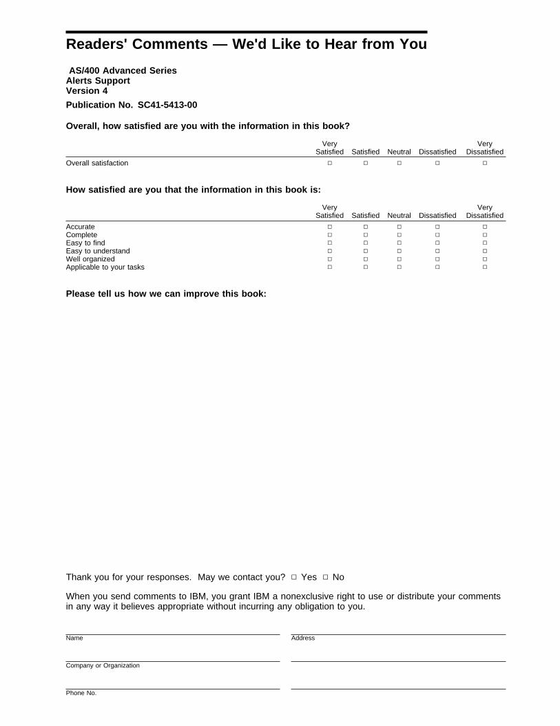
Readers' Comments — We'd Like to Hear from You
AS/400 Advanced SeriesAlerts SupportVersion 4
Publication No. SC41-5413-00
Overall, how satisfied are you with the information in this book?
How satisfied are you that the information in this book is:
Please tell us how we can improve this book:
Thank you for your responses. May we contact you? Ø Yes Ø No
When you send comments to IBM, you grant IBM a nonexclusive right to use or distribute your commentsin any way it believes appropriate without incurring any obligation to you.
Name Address
Company or Organization
Phone No.
Very
Satisfied Satisfied Neutral DissatisfiedVery
Dissatisfied
Overall satisfaction Ø Ø Ø Ø Ø
Very
Satisfied Satisfied Neutral DissatisfiedVery
Dissatisfied
Accurate Ø Ø Ø Ø ØComplete Ø Ø Ø Ø ØEasy to find Ø Ø Ø Ø ØEasy to understand Ø Ø Ø Ø ØWell organized Ø Ø Ø Ø ØApplicable to your tasks Ø Ø Ø Ø Ø

Cut or FoldAlong Line
Cut or FoldAlong Line
Readers' Comments — We'd Like to Hear from YouSC41-5413-00 IBM
Fold and Tape Please do not staple Fold and Tape
NO POSTAGENECESSARYIF MAILED IN THEUNITED STATES
BUSINESS REPLY MAILFIRST-CLASS MAIL PERMIT NO. 40 ARMONK, NEW YORK
POSTAGE WILL BE PAID BY ADDRESSEE
IBM CORPORATIONATTN DEPT 2453605 HWY 52 NROCHESTER MN 55901-7829
Fold and Tape Please do not staple Fold and Tape
SC41-5413-00


IBM
Printed in the United States of Americaon recycled paper containing 10%recovered post-consumer fiber.
SC41-5413-ðð

Spine information:
IBM AS/400 Advanced Series Alerts Support Version 4