alchemist ph.c hd - grs systems€¦ · alchemist ph.c hd motion compensated conversion platform...
TRANSCRIPT

Alchemist Ph.C HD
Motion Compensated Conversion Platform
Snell & Wilcox Ltd., Southleigh Park House, Eastleigh Road, Havant, Hants, PO9 2PE, United Kingdom.For General Enquiries contact: Tel: +44 (0) 2392 489000 Fax: +44 (0)23 9245 1411
For Technical assistance contact: Tel: +44 (0) 2392 489058 Fax: +44 (0) 2392 489057Web: http://www.snellwilcox.com/support
Ftp: ftp://ftp.snellwilcox.com/support
© March 2009
Operator’sManual


Version 2 Issue 2 www.snellwilcox.com / www.pro-bel.com Alchemist Ph.C HD
ContentsSafety Information ................................................................................................................................ v
Information and Notices...................................................................................................................... xi
Product Support Procedure.............................................................................................................. xiii
Section 1: Introduction......................................................................................................................... 1Description.................................................................................................................................... 1Features........................................................................................................................................ 2Technical Profile ........................................................................................................................... 3Installation................................................................................................................................... 12
Unpacking the Unit ................................................................................................................ 12Removing the Transit Bar ...................................................................................................... 12
Connecting Power to the Alchemist Ph.C................................................................................... 13Power Inlets and Power Supply Switches ............................................................................. 13Power Supply LEDs............................................................................................................... 13Power Supplies...................................................................................................................... 13Supply Voltage ...................................................................................................................... 14
Environment................................................................................................................................ 14Handling Precautions.................................................................................................................. 14Connections................................................................................................................................ 15
Inputs ..................................................................................................................................... 15Outputs .................................................................................................................................. 16Communication Connections................................................................................................. 16
Section 2: Operation........................................................................................................................... 21General Operating Principles...................................................................................................... 21Operation Using the Front Panel Touch Screen Interface.......................................................... 22
Overview................................................................................................................................ 22Main Toolbar Selections ........................................................................................................ 22Warnings and Notifications .................................................................................................... 22Panel Lock............................................................................................................................. 23Timeout.................................................................................................................................. 23Selecting Parameters and Making Adjustments .................................................................... 24Selecting Specific Functions.................................................................................................. 25
Video Menus............................................................................................................................... 26Input....................................................................................................................................... 27Conversion............................................................................................................................. 30Aspect Control ....................................................................................................................... 35Proc Amp............................................................................................................................... 43Output A and Output B .......................................................................................................... 47Reference .............................................................................................................................. 53Utilities ................................................................................................................................... 55
Audio Menus............................................................................................................................... 60Audio Display Tab.................................................................................................................. 61Audio Control ........................................................................................................................ 62Audio Control (Audio Pair 1 to Audio Pair 8) ....................................................................... 63Audio Pair 1 to Audio Pair 8 (PCM/Data Controls) ................................................................ 64Audio Pair 1 Source to Audio Pair 8 Source.......................................................................... 66Dolby E .................................................................................................................................. 67Encoder ................................................................................................................................. 70
i

Alchemist Ph.C HD www.snellwilcox.com / www.pro-bel.com Version 2 Issue 2
Timecode Menus ........................................................................................................................ 71Timecode Display .................................................................................................................. 72Timecode Setup..................................................................................................................... 73Timecode Control .................................................................................................................. 76
FilmTools .................................................................................................................................... 79Enabling FilmTools ................................................................................................................ 80FilmTools Input ...................................................................................................................... 81FilmTools Output ................................................................................................................... 86FilmTools Control................................................................................................................... 90FilmTools Detection ............................................................................................................... 91
Status.......................................................................................................................................... 94Messages .............................................................................................................................. 94
System Functions ....................................................................................................................... 95RollCall .................................................................................................................................. 96Ethernet ................................................................................................................................. 99Panel Controls ....................................................................................................................... 99Setup ................................................................................................................................... 101Info....................................................................................................................................... 102Debug .................................................................................................................................. 103
Memory..................................................................................................................................... 106
Appendix A: Noise Reduction ......................................................................................................... 107Overview................................................................................................................................... 107Noise Reducer Controls............................................................................................................ 107Setup ........................................................................................................................................ 107
Basic Operation ................................................................................................................... 107Advanced Setup and Operation........................................................................................... 108
Appendix B: Timecode ..................................................................................................................... 111Overview................................................................................................................................... 111Key Features ............................................................................................................................ 111Control Interface ....................................................................................................................... 112
Input Timecode Setup.......................................................................................................... 112Output Timecode Setup....................................................................................................... 113
Timecode Control ..................................................................................................................... 115Input Timecode.................................................................................................................... 115Timecode Entry.................................................................................................................... 115Input Trigger ........................................................................................................................ 115Output A Load ..................................................................................................................... 115Output B Load ..................................................................................................................... 116Prerun.................................................................................................................................. 116Output A Timecode.............................................................................................................. 116Output B Timecode.............................................................................................................. 116E-E Window......................................................................................................................... 116Manual Trigger..................................................................................................................... 116
Timecode Mode ........................................................................................................................ 117Timecode Modes at a Glance.............................................................................................. 117Synchro Auto ....................................................................................................................... 117Synchro Prerun.................................................................................................................... 118Synchro Manual................................................................................................................... 119E-E....................................................................................................................................... 119E-E Regen ........................................................................................................................... 120Freerun ................................................................................................................................ 120Trigger Load ........................................................................................................................ 120
ii

Version 2 Issue 2 www.snellwilcox.com / www.pro-bel.com Alchemist Ph.C HD
Timecode Control Warnings ................................................................................................ 120Operational Example ........................................................................................................... 121
Questions & Answers ............................................................................................................... 127
Appendix C: RGB Legalizer and Luma Clipper.............................................................................. 129RGB Legalizer Overview .......................................................................................................... 129RGB Legalizer Controls ............................................................................................................ 130Luma Clipper Overview ............................................................................................................ 130Luma Clipper Controls .............................................................................................................. 130
Appendix D: FilmTools..................................................................................................................... 133Overview................................................................................................................................... 133FilmTools Control Interface....................................................................................................... 134
Enabling FilmTools .............................................................................................................. 135FilmTools Input .................................................................................................................... 136FilmTools Output ................................................................................................................. 141FilmTools Control................................................................................................................. 145FilmTools Detection ............................................................................................................. 146
Operational Examples .............................................................................................................. 149Operational Example 1 ........................................................................................................ 149Operational Example 2 ........................................................................................................ 149Operational Example 3 ........................................................................................................ 149Operational Example 4 ........................................................................................................ 150Operational Example 5 ........................................................................................................ 150
Conversion Tables.................................................................................................................... 151Understanding Datum TC Conversion...................................................................................... 154
2:3 TC Datum with ‘On Valid TC’ ........................................................................................ 1542:3 TC Datum with ‘At Datum’ ............................................................................................ 154
Understanding 2:3 Datum Cadence ......................................................................................... 156Genlock & FilmTools................................................................................................................. 156Questions & Answers ............................................................................................................... 157FilmTools Glossary ................................................................................................................... 158
Appendix E: Dolby E......................................................................................................................... 161Overview................................................................................................................................... 161Dolby® E Control Interface ....................................................................................................... 162
Audio Display Tab (Home Screen) ...................................................................................... 162Audio Control ...................................................................................................................... 164Audio Control (Audio Pair 1 to Audio Pair 8) ..................................................................... 165Audio Pair 1 to Audio Pair 8 (PCM/Data Controls) .............................................................. 166Audio Pair 1 Source to Audio Pair 8 Source........................................................................ 168Dolby E ................................................................................................................................ 169Encoder ............................................................................................................................... 172
Configuring Dolby E Alignment................................................................................................. 173Calculating Dolby E Audio Delay Transcoding ......................................................................... 174Questions & Answers ............................................................................................................... 176
Appendix F: Latency Tables ............................................................................................................ 179
Appendix G: RollTrack Audio Delay Tracking ............................................................................... 189
Manual Revision Record .................................................................................................................. 195
iii

Alchemist Ph.C HD www.snellwilcox.com / www.pro-bel.com Version 2 Issue 2
iv

Version 2 Issue 2 www.snellwilcox.com / www.pro-bel.com Alchemist Ph.C HD
Safety Information
Explanation of Safety SymbolsThis symbol refers the user to important information contained in the accompanying literature. Refer to manual.
This symbol indicates that hazardous voltages are present inside. No user serviceable parts inside. This unit should only be serviced by trained personnel.
Servicing instructions where given, are for use by qualified service personnel only. To reduce risk of electric shock do not perform any servicing other than that contained in the operating instructions unless you are qualified to do so. Refer all servicing to qualified personnel.
To reduce the risk of electric shock, do not expose this appliance to rain or moisture.
Always ensure that the unit is properly earthed and power connections correctly made.
This equipment must be supplied from a power system providing a PROTECTIVE EARTH connection and having a neutral connection which can be reliably identified.
The power outlet supplying power to the unit should be close to the unit and easily accessible
Power connection in countries other than the USAThe equipment is normally shipped with a power cable with a standard IEC moulded free socket on one end and a standard IEC moulded plug on the other. If you are required to remove the moulded mains supply plug, dispose of the plug immediately in a safe manner.
The colour code for the lead is as follows:
GREEN/YELLOW lead connected to E (Protective Earth Conductor)BLUE lead connected to N (Neutral Conductor)BROWN lead connected to L (Live Conductor)
Caution If the unit has two mains supply inputs ensure that both power cords are plugged into mains outlets operating from the same phase.
L N
E
N L
E
GB
! CAUTIONRISK OF ELECTRIC SHOCKDO NOT REMOVE COVERS
NO USER SERVICEABLE PARTSREFER SERVICING TO QUALIFIED
PERSONNEL ONLY
!
!
Safety Warnings
Erklärung der SicherheitssymboleDieses Symbol weist den Benutzer auf wichtige Informationen hin, die in der begleitenden Dokumentation enthalten sind.
Dieses Symbol zeigt an, dass gefährliche Spannung vorhanden ist. Es befinden sich keine vom Benutzer zu wartenden Teile im Geräteinneren. Dieses Gerät sollte nur von geschultem Personal gewartet werden
Um das Risiko eines Elektroschocks zu reduzieren, setzen Sie das Gerät weder Regen noch Feuchtigkeit aus.
Stellen Sie immer sicher, dass das Gerät ordnungsgemäß geerdet und verkabelt ist.
Dieses Equipment muss an eine Netzsteckdose mit Schutzleiter angeschlossen werden und einen zuverlässig identifizierbaren Nullleiter haben.
Die Netzsteckdose sollte nahe beim Gerät und einfach zugänglich sein.
Netzanschluss in anderen Ländern als der USADas Equipment wird im Normalfall mit einem Netzkabel mit Standard IEC Anschlussbuchse und einem Standard IEC Anschlussstecker geliefert. Sollten Sie den angeschweißten Stecker auswechseln müssen, entsorgen Sie diesen bitte umgehend. Die farbliche Belegung des Netzkabels ist wie folgt:
GRÜN GELB E = Schutzleiter BLAU N = NulleiterBRAUN L = P = Phase
Achtung: Wenn das Gerät zwei Anschlussbuchsen hat, stellen Sie bitte sicher, dass beide Netzkabel mit der selben Phase in die Netzsteckdose gesteckt werden.
Sicherheits-Warnhinweise
D
!
!
Die angeführten Service-/Reparatur-Anweisungen sind ausschließlich von qualifiziertem Service-Personal auszuführen. Um das Risiko eines lektroschocks zu reduzieren, führen Sie ausschließlich die im Benutzerhandbuch eschriebenen Anweisungen aus, es sei denn, Sie haben die entsprechende Qualifikation. Wenden Sie sich in allen Service-Fragen an qualifiziertes Personal.
! ACHTUNGGefahr von Elektroschocks.
Abdeckungen nicht entfernenKeine vom Benutzer zu wartende Teile
Wenden Sie sich ausschließlichan qualifiziertes Personal
L =Phase
N =Nulleiter
N =Nulleiter
L =Phase
E =Schutzleiter
E =Schutzleiter
Légende :Ce symbole indique qu'il faut prêter attention et se référer au manuel.
Ce symbole indique qu'il peut y avoir des tensions électriques à l'intérieur de l'appareil. Ne pas intervenir sans l'agrément du service qualifié.
Pour réduire le risque de choc électrique, ne pas exposer l'appareil dans un milieu humide.
Toujours s'assurer que l'unité est correctement alimentée, en particuliers à la liaison à la terre.
La source électrique de cet équipement doit posséder une connexion à la terre , ainsi qu'une liaison « neutre » identifiable.
La prise électrique qui alimente l'appareil doit être proche de celle-ci et accessible.
Câble secteur de pays autres que les Etats-Unis L'équipement est livré avec un câble secteur au standard IEC, moulé mâle/femelle.Si vous souhaitez changr la prise mâle de votre cordon, voici les codes couleurs des fils :
Le fil VERT/JAUNE est connecté à T (Terre)Le fil BLEU est connecté à N (Neutre)Le fil MARRON est connecté à P (Phase)
Attention si l'appareil a 2 alimentations, s'assurer que les cordons soient branchés sur la même phase.
Précaution d'emploi :
F
Les procédures de maintenance ne concernentque le service agréé. Afin de réduire le risque de choc électrique, il est recommandé de se limiter aux procédures d'utilisation, à moins d'en être qualifié.Pour toute maintenance, contacter le service compétent.
! ATTENTIONRISQUE DE CHOC ELECTRIQUE
NE PAS RETIRER LE COUVERCLENE PAS INTERVENIR SANSL'AGREMENT DU SERVICE
QUALIFIE
P N
T
N P
T
Connecteur Prise
!
!
Explicación de los Símbolos de SeguridadÉste símbolo refiere al usuario información importante contenida en la literatura incluida. Referirse al manual.
Éste símbolo indica que voltajes peligrosos están presentes en el interior. No hay elementos accesibles al usuario dentro.Esta unidad sólo debería ser tratada por personal cualificado.
Las instrucciones de servicio cuando sean dadas, son sólo para uso de personal cualificado. Para reducir el riesgo de choque eléctrico no llevar a cabo ninguna operación de servicio aparte de las contenidas en las instrucciones de operación, a menos que se esté cualificado para realizarlas. Referir todo el trabajo de servicio a personal cualificado.
Para reducir el riesgo de choque eléctrico, no exponer este equipo a la lluvia o humedad.
Siempre asegurarse de que la unidad está propiamente conectada a tierra y que las conexiones de alimentación están hechas correctamente.
Este equipo debe ser alimentado desde un sistema de alimentación con conexión a TIERRA y teniendo una conexión neutra fácilmente identificable.
La toma de alimentación para la unidad debe ser cercana y fácilmente accesible.
Conexión de alimentación en otros países que no sean USAEl equipo es normalmente entregado con un cable de alimentación con un enchufe hembra estándar IEC en un extremo y con una clavija estándar IEC en el otro. Si se requiere eliminar la clavija para sustituirla por otra, disponer dicha clavija de una forma segura. El código de color a emplear es como sigue:
Advertencia Si la unidad tuviera dos tomas de alimentación, asegurarse de que ambos cables de alimentación están conectados a la misma fase.
ESP
!
!
Advertencias de Seguridad
L N
E
N L
E
ClavijaAerea Macho
EnchufeAereo Hembra
VERDE/ AMARILLO conectado a E (Conductor de protección a Tierra -Earth en el original-)AZUL conectado a N (Conductor Neutro -Neutral en el original-)MARRÓN conectado a L (Conductor Fase -Live en el original-)
RIESGO DE CHOQUE ELECTRICONO QUITAR LAS PROTECCIONNESELEMENTOS NO ACCESIBLES ALUSUARIO.SERVICIO SOLAMENTE A PERSONALCUALIFICADO
v

Alchemist Ph.C HD www.snellwilcox.com / www.pro-bel.com Version 2 Issue 2
Simboli di sicurezza:Questo simbolo indica l'informazione importante contenuta nei manuali appartenenti all'apparecchiatura. Consultare il manuale.
Questo simbolo indica che all'interno dell'apparato sono presenti tensioni pericolose. Non cercare di smontare l'unità. Per qualsiasi tipo di intervento rivolgersi al personale qualificato.
Le istruzioni relative alla manutenzione sono ad uso esclusivo del personale qualificato. E' proibito all'utente eseguire qualsiasi operazione non esplicitamente consentita nelle istruzioni. Per qualsiasi informazione rivolgersi al personale qualificato.
Per prevenire il pericolo di scosse elettriche è necessario non esporre mai l'apparecchiatura alla pioggia o a qualsiasi tipo di umidità.
Assicurarsi sempre, che l'unità sia propriamente messa a terra e che le connessioni elettriche siano eseguite correttamente.
Questo dispositivo deve essere collegato ad un impianto elettrico dotato di un sistema di messa a terra efficace.
La presa di corrente deve essere vicina all'apparecchio e facilmente accessibile.
Connessione elettrica nei paesi diversi dagli Stati UnitiL'apparecchiatura normalmente è spedita con cavo pressofuso con la presa e spina standard IEC. Nel caso della rimozione della spina elettrica, gettarla via immediatamente osservando tutte le precauzioni del caso. La leggenda dei cavi è la seguente:
VERDE/GIALLO cavo connesso ad "E" (terra)BLU cavo connesso ad "N" (neutro)MARRONE cavo connesso ad "L" ( fase)
Attenzione! Nel caso in cui l'apparecchio abbia due prese di corrente, assicurarsi che i cavi non siano collegati a fasi diverse della rete elettrica.
I
!
!
Attenzione:
! ATTENZIONE
L N
E
N L
E
Presa volante Spina volante
RISCHIO DI SHOCK ELETTRICONON CERCARE DI SMONTARE
L'UNITA PER QUALSIASI TIPO DI INTERVENTO RIVOLGERSI AL
PERSONALE QUALIFICATO
Forklaring på sikkerhedssymbolerDette symbol gør brugeren opmærksom på vigtig information i den medfølgende manual.
Dette symbol indikerer farlig spænding inden i apparatet. Ingen bruger servicerbare dele i apparatet på brugerniveau. Dette apparat må kun serviceres af faglærte personer..
Serviceinstruktioner er kun til brug for faglærte servicefolk. For at reducere risikoen for elektrisk stød må bruger kun udføre anvisninger i betjeningsmanualen. Al service skal udføres af faglærte personer.
For at reducere risikoen for elektrisk stød må apparatet ikke udsættes for regn eller fugt.
Sørg altid for at apparatet er korrekt tilsluttet og jordet.
Dette apparat skal forbindes til en nettilslutning, der yder BESKYTTENDE JORD og 0 forbindelse skal være tydeligt markeret.
Stikkontakten, som forsyner apparatet, skal være tæt på apparatet og let tilgængelig.
Nettilslutning i andre lande end USAUdstyret leveres normalt med et strømkabel med et standard IEC støbt løst hunstik i den ene ende og et standard IEC støbt hanstik i den anden ende. Hvis et af de støbte stik på strømkablet er defekt, skal det straks kasseres på forsvarlig vis. Farvekoden for lederen er som følger:
GRØN/GUL leder forbundet til J (Jord)BLÅ leder forbundet til 0BRUN leder forbundet til F(Fase)
Forsigtig Hvis enheden har to lysnetindgange, skal der sørges for at begge ledninger tilsluttes lystnetudgange fra den samme fase.
DK
!
!
!
Sikkerhedsadvarsler
! FORSIGTIGRISIKO FOR ELEKTRISK STØD
DÆKPLADER MÅ IKKE FJERNESINGEN BRUGER SERVICERBARE
DELE SERVICE MÅ KUN UDFØRESAF FAGLÆRTE PERSONER
F 0
J
0 F
J
Han-stik Hun-stik
Förklaring av SäkerhetssymbolerDenna symbol hänvisar användaren till viktig information som återfinns i litteraturen som medföljer. Se manualen.
Denna symbol indikerar att livsfarlig spänning finns på insidan.Det finns inga servicevänliga delar inne i apparaten. Denna apparat få endast repareras av utbildad personal.
Serviceinstruktioner som anges avser endast kvalificerad och utbildad servicepersonal. För att minska risken för elektrisk stöt, utför ingen annan service än den som återfinns i medföljande driftinstruktionerna, om du ej är behörig. Överlåt all service till kvalificerad personal.
För att reducera risken för elektrisk stöt, utsätt inte apparaten för regn eller fukt.
Se alltid till att apparaten är ordentligt jordad samt att strömtillförseln är korrekt utförd.
Denna apparat måste bli försörjd från ett strömsystem som är försedd med jordadanslutning samt ha en neutral anslutning som lätt identifierbar.
Vägguttaget som strömförsörjer apparaten bör finnas i närheten samt vara lätttillgänglig.
Strömkontakter i länder utanför USAApparaten utrustas normalt med en strömkabel med standard IEC gjuten honkontakt på ena änden samt en standard IEC gjuten hankontakt på den andra änden. Om man måste avlägsna den gjutna hankontkaten, avyttra denna kontakt omedelbart på ett säkert sätt. Färgkoden för ledningen är följande:
GRÖN/GUL ledning ansluten till E (Skyddsjordad ledare)
BLÅ ledning ansluten till N (Neutral ledare)BRUN ledning ansluten till L (Fas ledare)
Varning! Om enheten har två huvudsakliga elförsörjningar, säkerställ att båda strömkablarna som är inkopplade i enheten arbetar från samma fas.
S
! CAUTIONRISK OF ELECTRIC SHOCKDO NOT REMOVE COVERS
NO USER SERVICEABLE PARTSREFER SERVICING TO QUALIFIED
PERSONNEL ONLY
!
!
Säkerhetsvarningar
L N
E
N L
E
Stickkontakt-Hane Stickkontakt-Hona
Turvamerkkien selitysTämä merkki tarkoittaa, että laitteen mukana toimitettu kirjallinen materiaali sisältää tärkeitä tietoja. Lue käyttöohje.
Tämä merkki ilmoittaa, että laitteen sisällä on vaarallisen voimakas jännite. Sisäpuolella ei ole mitään osia, joita käyttäjä voisi itse huoltaa. Huollon saa suorittaa vain alan ammattilainen.
Huolto-ohjeet on tarkoitettu ainoastaan alan ammattilaisille. Älä suorita laitteelle muita toimenpiteitä, kuin mitä käyttöohjeissa on neuvottu, ellet ole asiantuntija. Voit saada sähköiskun. Jätä kaikki huoltotoimet ammattilaiselle.
Sähköiskujen välttämiseksi suojaa laite sateelta ja kosteudelta.
Varmistu, että laite on asianmukaisesti maadoitettu ja että sähkökytkennät on tehty oikein.
Laitteelle tehoa syöttävässä järjestelmässä tulee olla SUOJAMAALIITÄNTÄ ja nollaliitännän on oltava luotettavasti tunnistettavissa.
Sähköpistorasian tulee olla laitteen lähellä ja helposti tavoitettavissa.
SähkökytkentäLaitteen vakiovarusteena on sähköjohto, jonka toisessa päässä on muottiin valettu, IEC-standardin mukainen liitäntärasia ja toisessa päässä muottiin valettu, IEC-standardin mukainen pistoliitin. Jos pistoliitin tarvitsee poistaa, se tulee hävittää heti turvallisella tavalla. Johtimet kytketään seuraavasti:
KELTA-VIHREÄ suojamaajohdin E-napaan SININEN nollajohdin N-napaanRUSKEA vaihejohdin L-napaan
Huom! Jos laitteessa on kaksi verkkojännitteen tuloliitäntää, niiden johdot on liitettävä verkkopistorasioihin, joissa on sama vaiheistus.
FI
!
!
Turvaohjeita
!SÄHKÖISKUN VAARA ÄLÄ AVAA
LAITTEEN KANSIA EI SISÄLLÄKÄYTTÄJÄLLE HUOLLETTAVIAOSIA HUOLTO AINOASTAAN
AMMATTILAISEN SUORITTAMANA
VAROITUS
L N
E
N L
E
Pistoliitin Liitäntärasia
vi

Version 2 Issue 2 www.snellwilcox.com / www.pro-bel.com Alchemist Ph.C HD
Power cable supplied for the USAThe equipment is shipped with a power cord with a standard IEC molded free socket on one end and a standard 3-pin plug on the other. If you are required to remove the molded mains supply plug, dispose of the plug immediately in a safe manner. The color code for the cord is as follows:
• “GREEN lead connected to E (Protective Earth Conductor) • “BLACK lead connected to L (Live Conductor)• “WHITE lead connected to N (Neutral Conductor)
Símbolos de SegurançaO símbolo triangular adverte para a necessidade de consultar o manual antes de utilizar o equipamento ou efectuar qualquer ajuste.
Este símbolo indica a presença de voltagens perigosas no interior do equipamento. As peças ou partes existentes no interior do equipamento não necessitam de intervenção, manutenção ou manuseamento por parte do utilizador. Reparações ou outras intervenções devem ser efectuadas apenas por técnicos devidamente habilitados.
As instruções de manutenção fornecidas são para utilização de técnicos qualificados. Para reduzir o risco de choque eléctrico, não devem ser realizadas intervenções no equipamento não especificadas no manual de instalações a menos que seja efectuadas por técnicos habilitados.
Para reduzir o risco de choque eléctrico, não expor este equipamento à chuva ou humidade.
Assegurar que a unidade está sempre devidamente ligada à terra e que as ligações à alimentação estão correctas.
O sistema de alimentação do equipamento deve, por razões de segurança, possuir ligação a terra de protecção e ligação ao NEUTRO devidamente identificada.
A tomada de energia à qual a unidade está ligada deve situar-se na sua proximidade e facilmente acessível.
Ligação da alimentação noutros países que não os EUAO equipamento é, normalmente, enviado com cabo de alimentação com ficha IEC fêmea standard num extremo e uma ficha IEC macho standard no extremo oposto. Se for necessário substituir ou alterar alguma destas fichas, deverá remove-la e elimina-la imediatamente de maneira segura. O código de cor para os condutores é o seguinte:
Condutor VERDE/AMARELO ligado a E (Terra)Condutor AZUL ligado a N (Neutro)Condutor CASTANHO ligado a L (Vivo).
Atenção: Se a unidade tem duas fontes de alimentação assegurar que os dois cabos de alimentação estão ligados a tomadas pertencentes à mesma fase.
P
!
!
Avisos de Segurança
L N
E
N L
E
Ficha Livre Tomada Livre
! CAUTIONRISK OF ELECTRIC SHOCKDO NOT REMOVE COVERS
NO USER SERVICEABLE PARTSREFER SERVICING TO QUALIFIED
PERSONNEL ONLY
vii

Alchemist Ph.C HD www.snellwilcox.com / www.pro-bel.com Version 2 Issue 2
For products with more than one power supply inlet
Handling Instructions
Safety StandardAlchemist Ph.C HD. conforms to the following standard:
EN60950-1: 2001Safety of Information Technology Equipment.
EMC StandardsThis unit conforms to the following standards:
EN 55103-1: 1996 (Environment E4)Electromagnetic Compatibility, Product family standard for audio, video, audio-visual and entertainment lighting control apparatus for professional use. Part 1. Emission
EN 55103-2: 1996 (Environment E2)Electromagnetic Compatibility, Product family standard for audio, video, audio-visual and entertainment lighting control apparatus for professional use. Part 2. ImmunityFederal Communications Commission Rules Part 15, Class A:2004
EMC EnvironmentThe product(s) described in this manual conform to the EMC requirements for, and are intended for use in: The controlled EMC environment (for example purpose-built broadcasting or recording studios), and the rural outdoor environment (far away from railways, transmitters, overhead power lines, etc.) E4The applicable environment is stated in the Technical Profile section of the product operation manual under “EMC Performance Information/Environment.”
EMC Performance InformationPlease refer to the Technical Profile/Specifications section of the product operation manual.EMC Performance of Cables and ConnectorsSnell & Wilcox products are designed to meet or exceed the requirements of the appropriate European EMC standards. In order to achieve this performance in real installations it is essential to use cables and connectors with good EMC characteristics.All signal connections (including remote control connections) shall be made with screened cables terminated in connectors having a metal shell. The cable screen shall have a large-area contact with the metal shell.COAXIAL CABLESCoaxial cables connections (particularly serial digital video connections) shall be made with high-quality double-screened coaxial cables such as Belden 1694 or BBC type PSF1/2M.
Caution! To reduce the risk of electric shock plug each power supply cord into separate branch circuits employing separate service grounds.
CAUTION
DO NOT ATTEMPT TO LIFT THE UNIT USING THE HANDLES
ATTACHED TO THE FRONT PANEL.
! !
viii

Version 2 Issue 2 www.snellwilcox.com / www.pro-bel.com Alchemist Ph.C HD
D-TYPE CONNECTORSD-type connectors shall have metal shells making good RF contact with the cable screen. Connectors having “dimples” which improve the contact between the plug and socket shells are recommended.
ix

Alchemist Ph.C HD www.snellwilcox.com / www.pro-bel.com Version 2 Issue 2
x

Version 2 Issue 2 www.snellwilcox.com / www.pro-bel.com Alchemist Ph.C HD
Information and NoticesAbout this ManualThis manual contains information for the operation of the Alchemist Ph.C HD unit.Update/revision sheets should replace existing pages when supplied by the agent or Snell & Wilcox Ltd.
Packing List The unit is supplied in a dedicated packing carton provided by the manufacturer and should not be accepted if delivered in inferior or unauthorized materials. Carefully unpack the carton and check for any shipping damage or shortages.Any shortages or damage should be reported to the supplier immediately. Enclosures:• Alchemist Ph.C HD• Power cable• Installation Manual• Operation Manual
Software Version AmendmentsThis unit is fitted with V4.0 of the software.
Manufacturers NoticeCopyright protection claimed includes all forms and matters of copyrightable material and information now allowed by statutory or judicial law or hereinafter granted, including without limitation, material generated from the software programs which are displayed on the screen such as icons, screen display looks etc.Reproduction or disassembly of embedded computer programs or algorithms prohibited.Copyrighted names:Microsoft Windows™Information in this manual and software are subject to change without notice and does not represent a commitment on the part of Snell & Wilcox Ltd. The software described in this manual is furnished under a license agreement and may not be reproduced or copied in any manner without prior agreement with Snell & Wilcox Ltd. or their authorized agents.No part of this publication may be transmitted or reproduced in any form or by any means, electronic or mechanical, including photocopy, recording or any information storage and retrieval system, without permission being granted, in writing, by the publishers or their authorized agents.
Important NoticeNo responsibility is taken by the manufacturer or supplier for any non-compliance to EMC standards due to incorrect installation.
xi

Alchemist Ph.C HD www.snellwilcox.com / www.pro-bel.com Version 2 Issue 2
xii

Version 2 Issue 2 www.snellwilcox.com / www.pro-bel.com Alchemist Ph.C HD
Product Support ProcedureIf you experience any technical or operational difficulties with a Snell & Wilcox product please do not hesitate to contact us or utilize our online form to request assistance. There is a lot of information you can give us that will enable us to diagnose your problem swiftly. Please read the following guidelines, as these suggestions will help us to help you.
Basic InformationFor Units
Please provide the exact product Model, unit Serial Number and Software Version information.
For Cards or ModulesPlease provide the Sub-Assembly Number, card Serial Number and the Soft-ware Version information.
Basic ApplicationInputs
Please provide full details of the Input Signals being used including any refer-ences etc. and where they are being generated.
OutputsPlease provide full details of the Output Signals required and how they are being monitored.
SystemPlease provide a brief description of the system in which your S&W equip-ment is currently being used.
Basic Tests Preset Unit
Please use the Preset Unit function to return the settings back to the factory default.
RollCallIs your unit currently connected to a RollCall capable PC? This software is obtainable free of charge and provides a very user friendly GUI for virtually all S&W equipment - perfect for complex products, large systems or those with passive front panels.
Card Edge Info.What is the status of the card edge LEDs or display? These can often provide information such as power status and input detection conditions.
Internal TPGMany S&W products have an internal test pattern/tone generator. Please acti-vate this to assist you with your problem analysis.
In addition to the above, please do not forget to provide us with all of the necessary contact information:• Names • Telephone & Fax numbers • e-mail addresses • Business address A form has been provided for this information and will be found on the next page or an on line form is available on the Snell & Wilcox Web site at: http://www.snellwilcox.com/support
xiii

Alchemist Ph.C HD www.snellwilcox.com / www.pro-bel.com Version 2 Issue 2
Product Support Request Form* Indicates required information.
Name:*
Company:*
Address:*
Postal/Zip Code:
Country:*
Telephone:*
Fax:
Email*
Local S&W Center:*
Product Name:*
Product Type:*
Unit Serial Number:*
Fault/Spare Part Informa-tion:*
(please advise us how many units show this fault and the
system layout showing all other manufacturers' products)
Preferred Method of Con-tact:*
Please mail to:Snell & Wilcox Ltd.,Southleigh Park House, Eastleigh Road, Havant, Hants, PO9 2PE. United Kingdom.
Service contact information:Tel: +44 (0) 2392 489058Fax: +44 (0) 2392 489057Web: http://www.snellwilcox.com/supportFtp: ftp//ftp.snellwilcox.com/support
xiv

Version 2 Issue 2 www.snellwilcox.com / www.pro-bel.com Alchemist Ph.C HD
Section 1: IntroductionDescription
The Alchemist Ph.C HD's conversion quality is guaranteed through the utilization of the company's Emmy® award-winning Ph.C motion measurement technology. Ph.C algorithms, which have been continuously refined since the introduction of the first Alchemist Ph.C in 1992, have been optimized to prevent motion-related artifacts in high-definition video. The resulting output images are clear, sharp and free from the motion artifacts commonly associated with standards conversion. With Alchemist Ph.C HD, high-definition content including news, sports, live events and entertainment programming can now be broadcast around the globe in multiple high-definition standards and formats without degradation of image quality. Alchemist Ph.C HD automatically processes image movement to produce clear, smooth motion with the widest range of input material on the largest HD video displays.Alchemist Ph.C HD provides a complete one-box system solution that can easily integrate into any broadcast facility. It features the ability to convert between all commonly used HD broadcast standards and formats and has been architected to accommodate new standards as they emerge, thus future-proofing the investment of customers. Alchemist Ph.C HD is also capable of cross conversion, up conversion and down conversion of the same and different frame rates, making it a truly universal conversion platform.
Page 1

Alchemist Ph.C HD www.snellwilcox.com / www.pro-bel.com Version 2 Issue 2
Features• Compact 3RU size - practical for portable applications as well as mobiles,
studio installation and rental• Top performance: Ultimate in video conversion performance using Ph.C - no
complaints about conversion quality!• User Interface: Intuitive color touch screen• Dual redundant PSUs: helps ensure continuous on-air live operation• Video I/Os: HD SDI • Audio I/Os: Embedded and AES• CleanCut video cuts at the input appear as cuts at the output, maintaining the
precise look of the material• Ability to seamlessly handle timecode whilst performing a frame-rate conver-
sion.• All in one box: easy installation and low engineering risk
Output HD SDI SD SDI
1080i 720p 576i 480i
Alchemist Ph.C HD
Conversions 25 29.97 50 59.94 25 29.97
25 Pass Thru
Cross Frame Cross Cross
Frame Down Down Frame 1080i
29.97 Cross Frame
Pass Thru
Cross Frame Cross Down
Frame Down
50 Cross Cross Frame
Pass Thru
Cross Frame Down Down
Frame
HD SDI
720p 59.94 Cross
Frame Cross Cross Frame
Pass Thru
Down Frame Down
576i 25 Up Up Frame Up Up
Frame Pass Thru
Cross Frame
Inpu
t
SD SDI 480i 29.97 Up
Frame Up Up Frame Up Cross
Frame Pass Thru
Page 2

Version 2 Issue 2 www.snellwilcox.com / www.pro-bel.com Alchemist Ph.C HD
Technical Profile
Signal Inputs
Serial Digital 2 x 75 Ohm SD/HD Serial Digital with embedded audio (4 Groups)Input Standards: 1.5 Gbit/s HD-SDI SMPTE292M/SMPTE299M270M Mbit/s SD-SDI SMPTE259M
Reference 2 x loop-through HDTV Trisync/SD Bi-sync (Black & Burst) SMPTE 240M/274M,with autoselection dependant on output standard
Audio AES 8 channels unbalanced AES-3 via BNC connectors (75 Ohm)
Signal Outputs
Serial Digital Primary (Output A)
2 x 75 Ohm SD/HD Serial Digital with embedded audio (4 Groups)Output Standards: 1.5 Gbit/s HD-SDI SMPTE292M/SMPTE299M270M Mbit/s SD-SDI SMPTE259M
Serial Digital Secondary (Output B)
2 x 75 Ohm SD/HD Serial Digital with embedded audio (4 Groups)Output Standards: 1.5 Gbit/s HD-SDI SMPTE292M/SMPTE299M270M Mbit/s SD-SDI SMPTE259M
Audio AES 8 channels unbalanced AES-3 via BNC connectors (75 Ohm)
Communication Connections
RollCall Connection to a RollCall network via BNC connector, RS422, Ethernet.
Control Functions
Input Select Input A, Input B
Input Blanking Left, Right, Top Bottom
Input Loss Input, Freeze, Black
Input Standard SD525, 625SD/HDAuto525, 625,720p 50, 720p 59, 1080i 50, 1080i 59SD/HD with FilmTools525PsF29, 525i59, 625PsF23/24/25, 625i47/48, 625i50, 720P50, 720P59/60, 1080PsF23/24/25, 1080PsF29/30, 1080i47/48, 1080i50, 1080i59/60
Page 3
Alchemist Ph.C HD www.snellwilcox.com / www.pro-bel.com Version 2 Issue 2
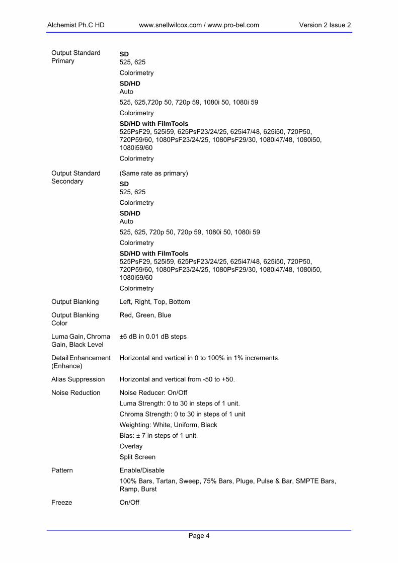
Output Standard Primary
SD525, 625ColorimetrySD/HDAuto525, 625,720p 50, 720p 59, 1080i 50, 1080i 59ColorimetrySD/HD with FilmTools525PsF29, 525i59, 625PsF23/24/25, 625i47/48, 625i50, 720P50, 720P59/60, 1080PsF23/24/25, 1080PsF29/30, 1080i47/48, 1080i50, 1080i59/60Colorimetry
Output Standard Secondary
(Same rate as primary)SD525, 625Colorimetry SD/HDAuto525, 625, 720p 50, 720p 59, 1080i 50, 1080i 59ColorimetrySD/HD with FilmTools525PsF29, 525i59, 625PsF23/24/25, 625i47/48, 625i50, 720P50, 720P59/60, 1080PsF23/24/25, 1080PsF29/30, 1080i47/48, 1080i50, 1080i59/60Colorimetry
Output Blanking Left, Right, Top, Bottom
Output Blanking Color
Red, Green, Blue
Luma Gain, Chroma Gain, Black Level
±6 dB in 0.01 dB steps
Detail Enhancement (Enhance)
Horizontal and vertical in 0 to 100% in 1% increments.
Alias Suppression Horizontal and vertical from -50 to +50.
Noise Reduction Noise Reducer: On/OffLuma Strength: 0 to 30 in steps of 1 unit.Chroma Strength: 0 to 30 in steps of 1 unitWeighting: White, Uniform, BlackBias: ± 7 in steps of 1 unit.OverlaySplit Screen
Pattern Enable/Disable100% Bars, Tartan, Sweep, 75% Bars, Pluge, Pulse & Bar, SMPTE Bars, Ramp, Burst
Freeze On/Off
Page 4

Version 2 Issue 2 www.snellwilcox.com / www.pro-bel.com Alchemist Ph.C HD
Monochrome On/Off
RGB Legalizer On/Off, 700mV, 721mV, 735mV
Luma Clipper On/OffWhite Max: 90% to 109% in steps of 1%White Knee 60% to 109% in steps of 1%Black Min.: -7% to 10% in steps of 1%Black Knee: -7% to 60% in steps of 1%
Conversion Functions
Convert Ph.C™ Motion Compensation,CleanCut™
Modes Up ConversionDown ConversionCross ConversionStandards Conversion
Ph.C Area 5 user definable keys with overlays to define active and inactive areas
Aspect Ratio Conversion
Fixed and custom aspect ratio conversions, which can be manually configured, stored and recalled from memory.
CleanCut™ On/OffF1/F2/Any
Transition Control On/OffField 1, Field 2, Any FieldSlew Duration: Absolute or proportional.Slew Duration Modes: Slow Out, Linear, Standard S-Curve, S-Curve, Slow In.
Aperture Presets for Sharp, Normal and Anti-Alias (Can be fine-tuned using Anti-Alias controls).
Audio Functions
Audio Select Embedded, AES
Audio Channel Selection
Group 1 pair 1, Group 1 pair 2Group 2 pair 1, Group 2 pair 2Group 3 pair 1, Group 3 pair 2Group 4 pair 1, Group 4 pair 2AES1, AES2AES3, AES4AES5, AES6,AES7, AES8
Audio Type PCM, Data
Name User can specify name of each audio pair
Tone On/Off, 1KHz -20dBFS, 4KHz -20dBFS, 1KHz -18dBFS, 4KHz -18dBFS
Mono On/Off
Page 5

Alchemist Ph.C HD www.snellwilcox.com / www.pro-bel.com Version 2 Issue 2
Mute On/Off
Pair Audio Delay Audio delay for each pair can be adjusted independently.
Timecode Functions (Optional)
Input Timecode Setup
SD Source
VITC VITCSMPTE 12M/SMPTE266M
LTC LTC ConnectorSMPTE 12M
HD Source
Emb VITC Embedded VITCSMPTE RP188
EMB LTC Embedded LTCSMPTE RP188
LTC LTC ConnectorSMPTE 12M
Frame Count Max
Auto, Detect, 24, 25, 30
Output Timecode Setup
Output A
Frame Count Max
Auto, 24, 25, 30
Drop Frame Mode
DF/NDFSynchro and Freerun modes only.59.94 output rates only.
SD VITC
625 Range Lines 6/319 and 20/333SMPTE 12M and SMPTE 266M
625 Default Lines 19/332 and 21/334SMPTE 266M
525 Range Lines 10/273 and 17/280SMPTE 12M and SMPTE 266M)
525 Default Lines 14/277 and 16/279SMPTE 266M and RP164
SD Activate
VITC Enables insertion of VITC
Repeat Enables repeat of VITC two lines after selected line
Page 6

Version 2 Issue 2 www.snellwilcox.com / www.pro-bel.com Alchemist Ph.C HD
HD Activate
Embedded VITC Enables insertion of VITC
Embedded LTC Enables insertion of embedded LTC
LTC Always enabled, follows output A
Timecode Control
Input Timecode Status DisplayInput timecode from selected source and DF/NDF state.
Output A Timecode Status DisplayOutput timecode generated by the Alchemist and DF/NDF mode.
Output B Timecode Status DisplayOutput timecode generated by the Alchemist and DF/NDF mode.
Timecode Entry 00:00:00:00 to 23:59:59:29Presets 01:00:00:00, 10:00:00:00
Input Trigger Set from Input timecode or the timecode entry window.Synchro & Freerun modes.
Manual Trigger Manual triggerSynchro and Freerun modes.
Output A Load Set from Input timecode or the timecode entry window. Synchro & Freerun modes.
Output B Load Set from Input timecode or the timecode entry window. Synchro & Freerun modes.
Prerun Synchro Prerun mode setup time.
EE Window EE mode continuity window.
Mode Synchro, EE, Freerun, Trigger Load.
FilmTools Functions (Optional)
FilmTools Enable On, Off
Input Cadence Alignment Control
Auto Cadence defined by internal sequence detector unless PsF standard is detected.
Detect Cadence defined by internal sequence detector in all cases.
1:1 Incoming content interpreted as 1:1 cadence.
2:2 F1/2 (PsF) Incoming content interpreted as 2:2 F1/2 (PsF) cadence.
2:2 F2/1 Incoming content is interpreted as 2:2 F2/F1 (PsF) cadence.
2:3 TC Datum Incoming content interpreted as continuous 2:3 cadence derived from continuous input time code by identifying the specific 2:3 frame type and timecode of an input datum frame.
Page 7

Alchemist Ph.C HD www.snellwilcox.com / www.pro-bel.com Version 2 Issue 2
2:3 TC 0 and 5 Incoming content interpreted as continuous 2:3 cadence defined by a specific relationship to the frame count of non-drop frame input timecode.
2:3 Freerun Incoming content interpreted as continuous 2:3 cadence derived from an internal free running 2:3 cadence generator.
Output Cadence Alignment Control
Off Outgoing content follows input.
2:2 F1/2 (PsF) Outgoing content is generated with 2:2 F1/2 (PsF) cadence.
2:2 F2/1 Outgoing content is generated with 2:2 F2/1 cadence.
2:3 TC Datum Outgoing content is generated with continuous 2:3 cadence derived from continuous output timecode by identifying the specific 2:3 frame type and timecode of an output datum frame.
2:3 TC 0 and 5 Outgoing content is generated with continuous 2:3 cadence defined by a specific relationship to the frame count of non-drop frame timecode.
2:3 Freerun Outgoing content is generated with continuous 2:3 cadence derived from an internal free-running 2:3 cadence generator.
FilmTools Control Setup
Mode
Auto Automatically selects between synchronized or interpolated conversion depending on the input and output formats.
Synchronize Forces conversion by synchronization.
Interpolation Forces conversion by interpolation.
Film Aperture
Normal Maximizes vertical resolution from incoming film material. Optimum for most applications.
Sharp Maximum possible vertical resolution, less tolerant of film sequence detection errors.
Safe Most tolerant of film sequence detection errors.
FilmTools Detection Setup
Video Enable On: Allows the sequence detector to positively identify content as 1:1 (video).Off: The sequence detector will not identify video.
Film Enable
Any Allows the sequence detector to identify film of any cadence.
2:2 Forces the sequence detector to identify film as 2:2 cadence only.
2:3 Forces the sequence detector to identify film as 2:3 cadence only.
Animation Optimized sequence detection algorithm for animation only.
Off The sequence detector will not identify any content as film.
Bias Normal, Video 1, Video 2, Film 1, Film 2
Page 8

Version 2 Issue 2 www.snellwilcox.com / www.pro-bel.com Alchemist Ph.C HD
Window Control Allows sequence and cut detection to be restricted to specific areas of the image. Settings are:• Auto• Track Input Blanking• User (Defined by User window slider controls)
Window Overlay Enables an overlay that permits adjustment of the sequence cut/detection region. Settings are:• Off• Darken• Greyed
Dolby®E (Optional)
Processing
Dolby®E - 1 Channel
1 Dolby®E transcoder path
• 1 x Dolby®D/E decoder• 1 X Dolby®E encoder• Includes delays and rate converter
Dolby®E - 2 Channel
2 Dolby®E transcoder paths
• 2 x Dolby®D/E decoder• 2 x Dolby®E encoder• Includes delays and rate converter
Controls (per Dolby®E Channel)
Source Any Embedded or AES InputGroup 1 pair 1, Group 1 pair 2Group 2 pair 1, Group 2 pair 2Group 3 pair 1, Group 3 pair 2Group 4 pair 1, Group 4 pair 2AES1, AES2, AES3, AES4, AES5, AES6, AES7, AES8
Decode Input Alignment
Dolby®E is co-timed, advanced or delayed by one frame
Auto Re-align Automatic correction of guard band errors
Map AES monitor Enables automatic assignment of decoded Dolby®E audio to AES outputs (Embedded outputs unchanged)
Map decode Enables automatic assignment of decoded Dolby®E audio to both embedded and AES outputs
Status • Source type• Bit depth• Program configuration• Decoder source
Encode Output Alignment
Dolby®E is co-timed, advanced or delayed by one frame
Page 9

Alchemist Ph.C HD www.snellwilcox.com / www.pro-bel.com Version 2 Issue 2
Controls (Output)
Audio Channel Selection
Selectable for each output pair (1 to 8)AES [1:8]EMB [1:8]DEC1[1:4]DEC2 [1:4]ENC1ENC2
Input Type PCM – treat as PCM audio, rate-convert, delay and co-timeData – treat as data, and delay and co-timeDolby®E – automatic detection, pass through Dolby®E transcoder chain, delay and co-time.Up to two inputs may be selected depending on options loaded.
Status
Messages Booting, System OK, Fan Fail, Diagnostics Active, System Overheating, PSU Fault, Version Unknown.
System Functions
RollCall Unit ID, Unit Name, Log Server Name, RollTracks (1 - 8), Log Items.
Ethernet DHCP or manually configured.
Panel Controls Calibrate, Clean, Timeout, Dim
Setup Shaped Horizontal Blanking (On/Off), Active Line Length (On/Off), Analog Blanking (On/Off), Auto AES re-align, Minimum Delay
Info System (Version and build number)MIO (Version and build number)HMI (Version and build number)ME (Version and build number)FRP (Version and build number)Options fitted
Debug Tools: Input TC Overlay, Output A TC Overlay, Output B TC OverlayDiagnostics: MIO Autotest, HMI Autotest, ME Autotest
Memory Functions
Memory Up to 6 user setups can be saved in memory.
Power
Input Voltage Range
100 V to 240 V rms., 50/60 Hz
Mains Fuse Rating T 8 AH 250 V. (Each Power supply)
Maximum Input Current
7 - 3 A (Each Power supply)
Power Consumption 500 W
Page 10

Version 2 Issue 2 www.snellwilcox.com / www.pro-bel.com Alchemist Ph.C HD
Mechanical
Temperature 0 to 35° C operating
Cooling Axial fan, front-to-rear airflow
Weight Approximately 20 kg
Case Type 3 RU Rack Mounting
Dimensions 483 mm x 563 mm x 132 mm (w, d, h)
Page 11

Alchemist Ph.C HD www.snellwilcox.com / www.pro-bel.com Version 2 Issue 2
Installation
Unpacking the UnitThe unit is packed in a single cardboard box. The contents are as follows:• Alchemist Ph.C HD unit • 2 Power cables• 1 Operating Manual• 1 Installation Manual Unpack the box carefully and check for any shortages or shipping damage. Immediately report any shortages or damage to Snell and Wilcox Limited.Retain the packaging; this must be used in the event that the unit is returned to Snell & Wilcox.
.
Removing the Transit BarThe unit will function with the transit bar in place; however, before installing it into an enclosure, the transit bar must be removed.To remove the transit bar, open the front panel and remove the two screws and the transit bar as shown in the diagram below.
Warning! The ALCHEMIST Ph.C HD. unit weighs more than 18 kg. Appropriate manual handling precautions should be taken when lifting the unit.
Warning! The transit bar must be in place before transporting the Alchemist Ph.C. Failure to do so may result in damage to the unit.If you remove the transit bar to install the unit in an enclosure, ensure that you retain the transit bar and screws.
Page 12

Version 2 Issue 2 www.snellwilcox.com / www.pro-bel.com Alchemist Ph.C HD
Connecting Power to the Alchemist Ph.CNote: Before connecting power to the unit please refer to the safety warnings on page 6.
Power Inlets and Power Supply SwitchesMains power is supplied to the unit via two fused, filtered IEC connectors. The lower IEC connector (as viewed from the rear of the unit) powers the lower PSU.The rated current for each power supply is 7 - 3 A 100 V 240 V 50/60 Hz.The fuse rating for each power supply is T 8 AH 250 V.The On/Off switches for the power supplies are located on the rear panel adjacent to the power inlet connectors.
Power Supply LEDsWhen illuminated the green LED’s indicate that the power supplies are operational.
Power SuppliesThe Alchemist Ph.C HD supports dual power supplies for redundancy. For dual redundancy operation both power supplies must be powered up and functioning. The unit will work correctly with only one supply operating but would not have dual redundancy under those conditions.
PSU LEDs
Caution! To reduce the risk of electric shock plug each power supply cord into separate branch circuits employing separate service grounds.
Page 13

Alchemist Ph.C HD www.snellwilcox.com / www.pro-bel.com Version 2 Issue 2
Supply VoltageThe unit automatically senses the nominal supply voltage and sets itself up accordingly. No voltage adjustment procedure is required.
EnvironmentAlthough ruggedly constructed to meet the normal environmental requirements, it is important that there is a free flow of air at the front, rear and left side to dissipate the heat produced during operation. Installations should be designed to allow for this.
If the unit is to be rack mounted, first open the front panel; details are given above. The fixing “ears” behind the panel will be revealed and the unit can be mounted in the rack.
Handling Precautions• Touchscreen and TFT-LCD• Do not press or scratch the display using any object with a sharp edge or
end.• Do not use or store the product under a condition where it will be exposed to
after, organic solution or acid.• Do not use under direct sunlight.• Do not disassemble the touchscreen.• Clean with a soft cloth or a soft cloth with a neutral detergent or alcohol.
When contaminated by chemicals wipe them off immediately with caution so as to not to cause injury to the human body.
• The LCD Polarizer is made of a soft material and must be handled carefully.• Wipe off water drops or finger grease immediately. Long term contact with
water may cause discoloration or spots.• The TFT-LCD module incorporates glass that may break or crack if abused.
Please handle with care.• Do not expose the module to direct sunlight or intense ultraviolet rays for long
periods.• If LCD panel breaks, it is possible that the liquid crystal may escape from the
panel. Avoid contact with the eyes or mouth. If the liquid crystal comes in con-tact with any part of the body or clothes it should be washed off immediately with soap and water.
Caution! The ventilation holes on the rear of the unit must not be obscured or damage to the equipment may result.
Warning! The ALCHEMIST Ph.C HD. unit weighs more than 18 kg. Appropriate manual handling precautions should be taken when lifting the unit.Under no circumstances should the grip handles be used to lift the ALCHEMIST Ph.C HD. unit.
Page 14

Version 2 Issue 2 www.snellwilcox.com / www.pro-bel.com Alchemist Ph.C HD
ConnectionsAll the connectors are mounted on the rear of the unit, and are appropriately annotated.
InputsSDI A, SDI B These are the two SDI inputs via BNC connectors for 75 Ohms.
Genlock Reference Ref A and BTwo pairs of loop-through BNC connectors for 75 Ohms are provided that may be connected to external sources of reference signals.
AES InputsThese are the 8 AES inputs via BNC connectors for 75 Ohms.
LTC INA standard Longitudinal Time Code signal may be connected to this XLR connector.This input requires a mating male locking XLR connector. To remove the connector the release tab must be pushed in.
Page 15

Alchemist Ph.C HD www.snellwilcox.com / www.pro-bel.com Version 2 Issue 2
OutputsOutput A & Output BAlchemist Ph.C HD provides two pairs of HD/SD serial digital outputs.
AES OutputsThese are the 8 AES outputs via BNC connectors for 75 Ohms.
LTC OutThis XLR connector provides a standard Longitudinal Time Code signal.This output requires a mating female XLR connector.
Communication ConnectionsRollCallThe unit can be controlled via RollCall using the BNC connector, the Remote RS-422 9-way D-type connector, and Ethernet (control 10/100).
RS422This port is for factory use only.
Pin Function Direction
1 Ground
6 Tx signal common
2 Transmit A A Ph.C → Remote
7 Transmit B A Ph.C → Remote
Page 16

Version 2 Issue 2 www.snellwilcox.com / www.pro-bel.com Alchemist Ph.C HD
Control 10/100This RJ45 connector socket allows the unit to be connected to the RollCall 32-bit Control panel via an Ethernet connection.
3 Receive B A Ph.C ← Remote
8 Receive A A Ph.C ← Remote
4 Rx signal common
9 Ground
5 Spare
Warning! This connector is not intended for direct connection to a telecommunications network.
Pin Function Direction
Page 17

Alchemist Ph.C HD www.snellwilcox.com / www.pro-bel.com Version 2 Issue 2
GPIThe General Purpose Interfaces (GPI's) are accessed via a 25 way D type female connector. In the table GPI refers to inputs and GPO refers to outputs.
Pin Function
2 GPI 0 Signal
14 GPI 0 Return
3 GPI 1 Signal
15 GPI 1 Return
4 GPI 2 Signal
16 GPI 2 Return
5 GPI 3 Signal
17 GPI 3 Return
6 GPI 4 Signal
18 GPI 4 Return
7 GPI 5 Signal
19 GPI 5 Return
8 GPO 4 Signal
20 GPO 4 Return
9 GPO 5 Signal
21 GPO 5 Return
10 GPO 0 Signal
22 GPO 0 Return
11 GPO 1 Signal
23 GPO 1 Return
12 GPO 2 Signal
24 GPO 2 Return
13 GPO 3 Signal
25 GPO 3 Return
1 Ground
Page 18

Version 2 Issue 2 www.snellwilcox.com / www.pro-bel.com Alchemist Ph.C HD
GPI Connector Pin Numbers (D-type female connector on the unit)
The output (GPO) characteristics are as follows:
GPI OverviewThe GPI provides contact closure tally outputs that can be used to turn on lamps etc. The equivalent circuit of the GPI input is shown on the next page.
Operating Voltage Range 0 to ±60 V
(DC/AC peak)
Maximum Load current 1.0 A (AC/DC)
Maximum On-State Resistance @ Tamb =+25°C
500 mOhm
Minimum Off-State Resistance
@Tamb =+25°C,V=±48V 100 MOhm
On a standard machine when delivered, GPI inputs 0 to 5 select machine memories 1 to 6 and GPI outputs 0 to 5 provide tally outputs indicating which memory is selected
Note:
Page 19

Alchemist Ph.C HD www.snellwilcox.com / www.pro-bel.com Version 2 Issue 2
Page 20

Version 2 Issue 2 www.snellwilcox.com / www.pro-bel.com Alchemist Ph.C HD
Section 2: OperationGeneral Operating Principles
The Alchemist Ph.C HD is operated by means of the touch screen and the spin wheel located on the front of the unit.
Alternatively, the Alchemist Ph.C HD can be operated by means of a remote control panel via the RollCall system.
All of the operational parameters and selections available through the Alchemist Ph.C HD’s touch screen front panel are available using the RollCall Control panel on a RollCall enabled network.Refer to the touch screen control section for descriptions of the configuration and operation parameters.
Touchscreen Spinwheel
Page 21

Alchemist Ph.C HD www.snellwilcox.com / www.pro-bel.com Version 2 Issue 2
Operation Using the Front Panel Touch Screen Interface
OverviewAt start-up, the Home screen appears, displaying a block diagram of the unit’s current functionality and details of current selections.Items highlighted in yellow indicate that the control setting has been changed from its default value.All operational parameters and selections can be made by touching items on the screen. Settings can be changed using scroll bars or by using the spinwheel.
Main Toolbar Selections
• When a main toolbar item is selected, a green bar will appear under the item.• Touching the Back button returns the display to the previously selected
screen.• Touching the Home button returns the display to the Home screen from any
stage in the menu hierarchy.• Touching the Menus button reveals the last selected menus screen.• Touching the System button reveals the System screen.• Touching the Memory button reveals the Memory screen.
Warnings and NotificationsIf there is a major problem with a function, the color of the item on the Home screen will change from a blue background to red as shown in the example below. In this case, a problem is indicated with the input selection, for example, the signal may have been lost.Similarly, if there is a minor problem with a function, the color of the item on the Home screen will change from a blue background to orange.
If a control setting has been changed from the default or preset value, the function will become highlighted in yellow on this screen.
Note:
Page 22

Version 2 Issue 2 www.snellwilcox.com / www.pro-bel.com Alchemist Ph.C HD
Panel LockThe lock icon shows that the panel is unlocked and is operational. When this item is selected, the panel will be locked. A red line will appear under the lock icon to indicate this.
To unlock the panel, touch the lock icon, a dialog box will appear. Select Yes to unlock the panel or No to keep the panel locked
TimeoutThe panel will automatically lock after a timeout period and the dialog box shown below will appear. Select Unlock to unlock the panel or Cancel to leave the panel locked.The timeout period can be changed on the System screen. See page 95 for more information.
When the panel is locked, functions may still be selected but settings cannot be changed. This condition is indicated by the items appearing dimmed.
Note:
Page 23

Alchemist Ph.C HD www.snellwilcox.com / www.pro-bel.com Version 2 Issue 2
Selecting Parameters and Making AdjustmentsIn the example below, the Proc Amp item has been selected. This reveals a screen that allows the Proc Amp controls to be selected. The Gain is selected, the Gain adjustment screen appears.The values may be changed by using:• The spinwheel. This allows the last selected control (highlighted green) to be
adjusted.• The sliding scroll bar (Change Value).
• The Reduce or Increase (by fixed increments) Value control.
• The Preset function .• The direct Value Entry function.
• The preset values are shown above the symbol.When the direct Value Entry function is activated, a numerical keypad will be displayed. Values may be entered by touching the numbers on the keypad. This value will be shown in a box at the top right of the keypad area.Selecting OK enters the value and removes the keypad from the screen.Selecting Cancel removes the keypad from the screen without accepting the value.The button clears the last number entered.
Page 24
Version 2 Issue 2 www.snellwilcox.com / www.pro-bel.com Alchemist Ph.C HD
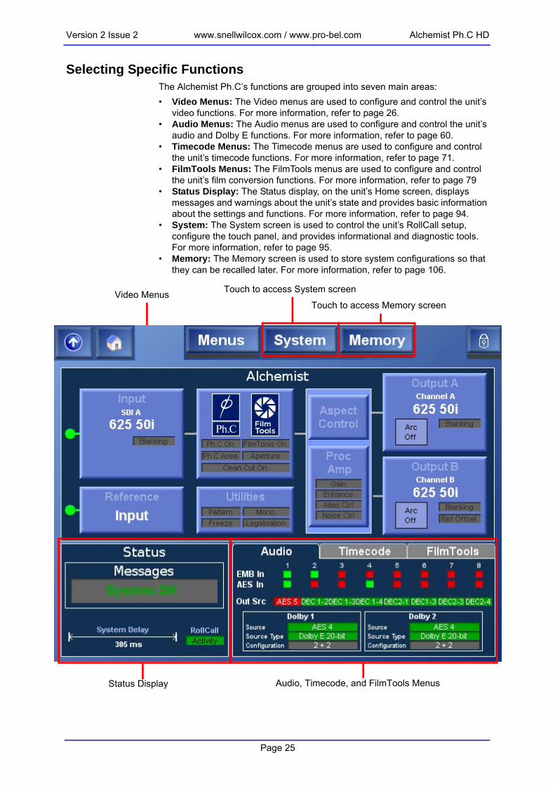
Selecting Specific FunctionsThe Alchemist Ph.C’s functions are grouped into seven main areas:• Video Menus: The Video menus are used to configure and control the unit’s
video functions. For more information, refer to page 26.• Audio Menus: The Audio menus are used to configure and control the unit’s
audio and Dolby E functions. For more information, refer to page 60.• Timecode Menus: The Timecode menus are used to configure and control
the unit’s timecode functions. For more information, refer to page 71.• FilmTools Menus: The FilmTools menus are used to configure and control
the unit’s film conversion functions. For more information, refer to page 79• Status Display: The Status display, on the unit’s Home screen, displays
messages and warnings about the unit’s state and provides basic information about the settings and functions. For more information, refer to page 94.
• System: The System screen is used to control the unit’s RollCall setup, configure the touch panel, and provides informational and diagnostic tools. For more information, refer to page 95.
• Memory: The Memory screen is used to store system configurations so that they can be recalled later. For more information, refer to page 106.
Video Menus Touch to access System screen
Touch to access Memory screen
Status Display Audio, Timecode, and FilmTools Menus
Page 25

Alchemist Ph.C HD www.snellwilcox.com / www.pro-bel.com Version 2 Issue 2
S
S
O
B
Video MenusThis section describes the Alchemist Ph.C HD video functions, which include the following configuration settings and controls:• Input: Use these settings to specify the input source, input, actions that the
unit should take upon signal loss and the input blanking settings. See “Input” on page 27.
• Conversion: Use these settings to enable or disable the Ph.C, and Clean Cut features, specify Aperture settings, and to set up Ph.C areas that can be used, for example, to protect transparent logos. See “Conversion” on page 30.
• Aspect Control: Use these settings to define the input aspect ratio, select preset output aspect ratios, and to perform custom aspect ratio adjustments. See “Aspect Control” on page 35.
• Proc Amp: Use these settings to adjust image gain and black level, enhance the image, and apply alias suppression and noise reduction. See “Proc Amp” on page 43.
• Output A & Output B: Use these settings to define the output standards, colorimetry settings, output border settings, output blanking, and to change the output names if desired. See “Output A and Output B” on page 47.
• Reference: Use these settings to enable and specify the source of the reference signal, and to adjust the relative timing of the reference signal to the output signal. See “Reference” on page 53.
• Utilities: Use these settings to enable a test pattern, specify the test pattern to be displayed, freeze the output picture, display the output as a mono-chrome image, and configure gamut legalisation. See “Utilities” on page 55.
Video
Input
ource
tandard
n Loss
lanking
Utilities
Pattern Enable
Pattern Type
Freeze
Monochrome
Legalizer
Processing (Conversion)
Ph.C
Clean Cut
Aperture
Ph.C Area
Aspect Control
Output A and Output B Mode
Manual ARC Settings
Forced Memory
Display Memory Setup
Proc Amp
Gain
Black Level
Enhance
Alias Suppresion
Noise Reduction
Output A & Output B
Output Standard
Colorimetry
Border
Output Blanking
Output Name
Reference
Reference Enable
Reference Source
Horizontal Timing
Vertical Timing
Page 26

Version 2 Issue 2 www.snellwilcox.com / www.pro-bel.com Alchemist Ph.C HD
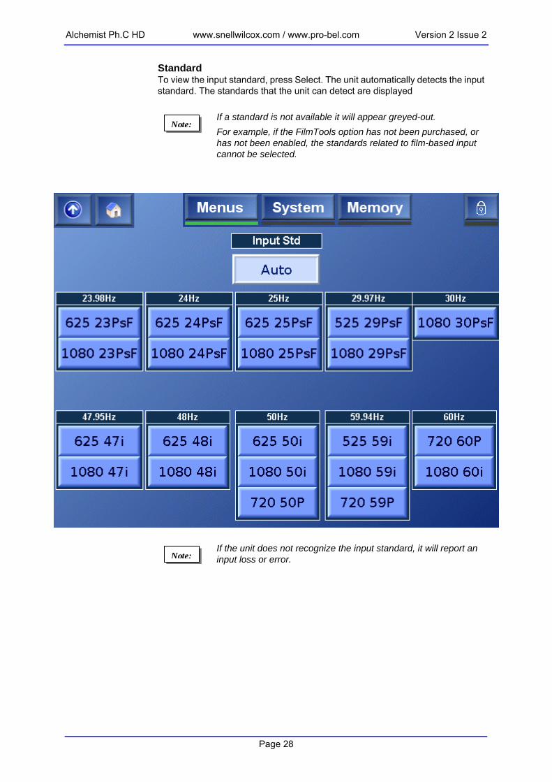
InputWhen Input is selected, the Input screen appears. Use this screen to specify the input signal options.
SourceThis allows either SDI A or SDI B to be selected as the input signal for the unit.
Page 27
Alchemist Ph.C HD www.snellwilcox.com / www.pro-bel.com Version 2 Issue 2
StandardTo view the input standard, press Select. The unit automatically detects the input standard. The standards that the unit can detect are displayed
If a standard is not available it will appear greyed-out.For example, if the FilmTools option has not been purchased, or has not been enabled, the standards related to film-based input cannot be selected.
Note:
If the unit does not recognize the input standard, it will report an input loss or error.Note:
Page 28

Version 2 Issue 2 www.snellwilcox.com / www.pro-bel.com Alchemist Ph.C HD
On LossThis specifies the action the Alchemist Ph.C HD will take in the event of an input loss.
ColorimetryThis function controls the color space conversion standard of the input signal. To specify the Colorimetry setting, touch Select and in the dialog box that appears, choose one of the following options:
BlankingThe Blanking function allows the adjustment of input blanking. It is used where the source video is known to have pixels/lines at the edge of the picture that are not required to be displayed. When set, the unit will blank any output data generated by the input data, regardless of the display control settings. The preset values are shown above the symbol.
Auto The most appropriate color space conversion for the signal is selected, as determined from the definition of the output video standard.
REC 601 Color space conversion to REC 601 standards is applied.
SMPTE 240 Color space conversion to SMPTE 240 standards is applied.
SMPTE 274 Color space conversion to SMPTE 274 standards is applied.
BT 709 Color space conversion to BT 709 standards is applied.
None No color space conversion is applied.
Left Adjusts the left-hand edge of blanking. A setting of 1 indicates that no input pixels that are normally visible should be blanked, 2 causes the first input pixel to be blanked, etc.
Page 29

Alchemist Ph.C HD www.snellwilcox.com / www.pro-bel.com Version 2 Issue 2
ConversionWhen Conversion is selected, the screen shown below is displayed. This function allows conversion options to be selected.
Ph.C (Phase Correlation)On selects motion compensated conversion and Off selects linear conversion.
FilmToolsOn enables the FilmTools options and Off disables the FilmTools options.For more information about FilmTools, see “FilmTools” on page 79 and “Appendix D: FilmTools” on page 133.
Right Adjusts the right-hand edge of blanking. A value equal to the number of active pixels per line in the current input standard indicates that no input pixels that are normally visible should be blanked. Subtracting 1 from this causes the last input pixel to be blanked, etc.
Top Adjusts the top edge of blanking. A setting of 1 indicates that no input lines that are normally visible should be blanked, 2 causes the first input line to be blanked, etc.
Bottom Adjusts the bottom edge of blanking. A value equal to the number of active pixels per line in the current input standard indicates that no input lines that are normally visible should be blanked. Subtracting 1 from this causes the last input line to be blanked, etc.
Page 30

Version 2 Issue 2 www.snellwilcox.com / www.pro-bel.com Alchemist Ph.C HD
ApertureThe Aperture settings are provided to maximize vertical resolution without introducing alias.The optimal Aperture setting is dependant on the quality of the source and the conversion being performed. For example, down converting sharp HD content to SD demands greater care with setup than an HD to HD cross conversion.Each Aperture can be fine tuned using the Alias Suppression control. See “Alias Suppression” on page 45.For each channel (A or B), the following Aperture adjustments can be made:• Sharp preserves the most vertical resolution from the input pictures.• Normal provides the best compromise for typical input pictures.• Anti-Alias is designed to prevent objectionable aliases in the output pictures.
CleanCut
CleanCut ensures no interpolation occurs between images either side of a cut. Under extreme circumstances, it may be necessary to disable CleanCut under the rare circumstance of a false cut being detected.
When configuring the Alchemist Ph.C to use both interlaced and progressive Outputs, two factors must be considered when setting CleanCut options:• Output A is always the primary Output and Output B is always the secondary
Output. • Field based cuts can only be made with an interlaced input.When both interlaced and progressive Outputs are required, and field-specific cuts are required on the interlaced Output, Output A must be interlaced and Output B progressive. If the Outputs are configured the other way around, there is no way of ensuring that cuts will occur on the correct field.
When the FilmTools option is enabled, the CleanCut concept of forcing a cut on field one or field two is not necessarily applicable.
Any Field
Cuts are Output on the closest Output field boundary to the detected input cut.
Field 1 Only
Cuts are restricted such that the first field of a new scene always begins on a field one.
Field 2 Only
Cuts are restricted such that the first field of a new scene always begins on a field two.
Note:
Page 31

Alchemist Ph.C HD www.snellwilcox.com / www.pro-bel.com Version 2 Issue 2
The table below illustrates the relationships between Primary/Secondary Outputs, the selected CleanCut mode, and the resulting cuts.
i = Interlaced (525, 625, 1080i 50, 1080i 59)P = Progressive (720p 50, 720p 59)
Output Format CleanCut
Primary (A) Secondary (B)
Cut Any Field
Cut Field 1
Cut Field 2
i i
i P
P i x x
P P x x
Page 32

Version 2 Issue 2 www.snellwilcox.com / www.pro-bel.com Alchemist Ph.C HD
Using the Alchemist Ph.C HD as a Frame SynchronizerIn instances where the input and Output are both interlaced, and of the same frame rate, the Alchemist Ph.C. HD functions as a frame synchronizer.If interlaced Output (in which the unit functions as a frame synchronizer) and progressive Output are both required, the interlaced Output should be set to Output A and the progressive Output should be set to Output B. If configured the other way it cannot be guaranteed that input dominance will be maintained.
i = Interlaced (525, 625, 1080i 50, 1080i 59)P = Progressive (720p 50, 720p 59)
Ph.C AreaSelecting Ph.C Area on the Conversion screen reveals the Ph.C Area screen.
The controls on the Ph. C Area screen allow Ph.C motion compensation to be disabled on certain areas of the image. Typical applications for this feature include protecting static computer generated captions overlaid onto dynamic sports coverage, or very small, low contrast, or transparent logos in front of dynamic action.
Primary (A) Secondary (B) Frame Synchronization
i i
i P
P i xP P x
Page 33

Alchemist Ph.C HD www.snellwilcox.com / www.pro-bel.com Version 2 Issue 2
This is done by specifying an active area and/or an inactive area of the image. The inactive area, when Enabled, is converted linearly. Any region outside the active area, if Enabled, will also be converted linearly. The remainder of the image will be converted using Ph.C motion compensation. To assist set up, a colored Overlay may be activated.The active area is shown in green, inactive in red.Up to five Key areas can be specified. These Key areas are numbered in ascending priority. That is, Key 2 has priority over Key 1, and so on. If two Keys overlap, the action specified for the area with the higher priority occurs.
Example source with dynamic video and logo. Colored overlay after adjustment to convert the source shown on the right.
Select Key To select a Key, press the corresponding Key button (Key 1 to Key 5). After selecting the Key, use the Key Controls to set up the Key area.
Reset All Keys
Press Reset All Keys to return all of the Keys to their default settings.
Key Control When the Enable option is selected, the Key area is enabled and can be adjusted.When the Active option is selected, the Key area will use motion-compensated conversion, and the Key overlay, if displayed, will appear in green. When it is not selected, the Key area will use linear conversion, and the Key overlay, if displayed, will appear in red.Use the slider controls (Left Edge, Right Edge, Top Edge, and Bottom Edge) to adjust the size and position of the selected Key area.Press Reset Key to return the selected Key to its default settings, leaving the other Keys unchanged.
Background When the Active option is selected, the background area uses Ph.C motion compensated conversion, and the background overlay, if displayed, appears in green. When the Active option is not selected, the background area uses linear conversion, and the background overlay, if displayed, appears in red.
Page 34
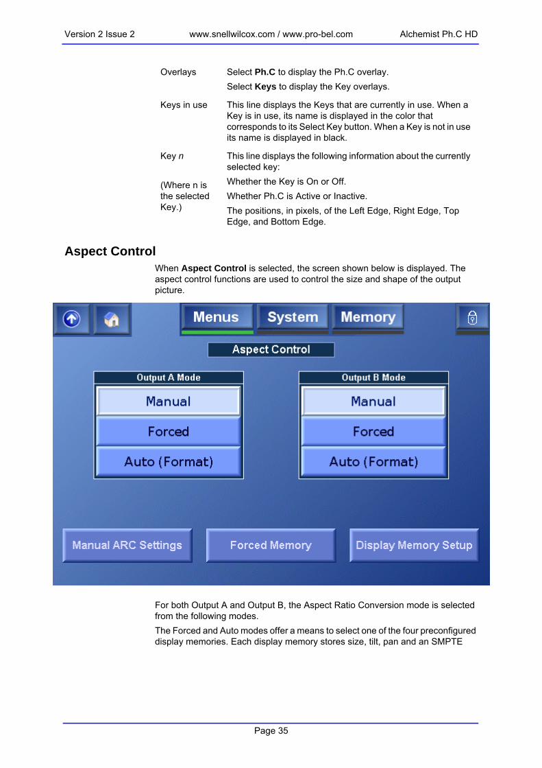
Version 2 Issue 2 www.snellwilcox.com / www.pro-bel.com Alchemist Ph.C HD
Aspect ControlWhen Aspect Control is selected, the screen shown below is displayed. The aspect control functions are used to control the size and shape of the output picture.
For both Output A and Output B, the Aspect Ratio Conversion mode is selected from the following modes.The Forced and Auto modes offer a means to select one of the four preconfigured display memories. Each display memory stores size, tilt, pan and an SMPTE
Overlays Select Ph.C to display the Ph.C overlay.Select Keys to display the Key overlays.
Keys in use This line displays the Keys that are currently in use. When a Key is in use, its name is displayed in the color that corresponds to its Select Key button. When a Key is not in use its name is displayed in black.
Key n
(Where n is the selected Key.)
This line displays the following information about the currently selected key:Whether the Key is On or Off.Whether Ph.C is Active or Inactive.The positions, in pixels, of the Left Edge, Right Edge, Top Edge, and Bottom Edge.
Page 35

Alchemist Ph.C HD www.snellwilcox.com / www.pro-bel.com Version 2 Issue 2
2016 code. Each display memory has a default configuration that can be reconfigured as required.
Manual Aspect Control
The aspect ratio conversion performed by the Alchemist Ph.C HD is determined by several interrelated factors:• The current input standard• The selected input aspect ratio• The current output standard• The selected aspect ratio conversion• Fixed aspect ratio adjustmentsInput Aspect RatioThe available input aspect ratio options are determined by the current input standard. Only those aspect ratios that are appropriate to the input standard will be displayed.
Manual This mode allows the ARC settings to be manually adjusted. Touch Manual ARC Settings to access the manual ARC controls
Forced This mode forces the display memory specified on the Forced Memory screen to be used. The settings for the Forced Memories are specified on the Display Memory Setup screen.
Auto (Format)
This mode automatically recalls the relevant display memory based in the Input/Output selection.
Page 36

Version 2 Issue 2 www.snellwilcox.com / www.pro-bel.com Alchemist Ph.C HD
To specify the input aspect ratio, touch the button that corresponds to the actual input aspect ratio.In turn, the selected input aspect ratio will determine the output aspect ratio options that are available for selection.Note that if the input standard is changed, the possible input aspect ratios will also change and the input aspect ratio will need to be reselected.Output Aspect Ratio (A and B)The available output aspect ratio conversions are determined by the selected input aspect ratio and the current output standard. Only those common aspect ratio conversions that are appropriate to both are displayed.To specify the output aspect ratio, touch the button that corresponds to the desired output aspect ratio.To lock the Channel B aspect ratio to that of Channel A, Select Lock to A.After selecting the output aspect ratio, the slider bars on the right are automatically adjusted to achieve the desired aspect ratio conversion.
Aspect Ratio AdjustmentsAfter the input and output aspect ratios have been set, these controls will have been automatically adjusted to achieve the desired conversion. However, it is possible to adjust aspect ratio conversion using these controls. For example, after selecting the aspect ratio conversion, the output image could be slightly overscanned by adjusting the size control.To adjust these controls, move the slider bars as required.
Note that if manual changes are made to the aspect ratio adjustments, they will be retained after the unit has been turned off. However, if a new fixed mode is selected they will be lost. If adjustments are made, store the setup in a user memory so that it can be recalled later.
Note that if the input standard, selected input aspect ratio, or output standard is changed, the possible output aspect ratio options will also change and the output aspect ratio will need to be reselected.
Size This adjusts the size of the whole image. Both vertical and horizontal size change together while maintaining the aspect ratio of the image. The range of control is from 40% to 200% in 0.01% steps.
Pan This adjusts the horizontal position of the output image. The range of control is ±75% in 0.01% steps.
Asp This adjusts the horizontal size of the image, allowing the shape (aspect ratio) of the output image to be changed. The range of control is from 50% to 150% in 0.01% steps.
Tilt This adjusts the vertical position of the output image. The range of control is ±75% in 0.01% steps.
Note:
Page 37

Alchemist Ph.C HD www.snellwilcox.com / www.pro-bel.com Version 2 Issue 2
Transition ControlWhen Transition Control is selected, the screen shown below is displayed. These controls are used to define the temporal control of a slewed transition. The profile is illustrated graphically on the front panel’s button.
Slew On/OffThese controls enable or disable the transition control settings.Transition Control
Any Slew transitions will occur on either field 1 or field 2.
Field 1 only Slew transitions will only occur on a field 1.
Field 2 only Slew transitions will only occur on a field 2.
Page 38

Version 2 Issue 2 www.snellwilcox.com / www.pro-bel.com Alchemist Ph.C HD
Slew Duration Mode
Slew Duration Unit
Slew DurationThis control defines the time it takes for a slewed transition to occur. The duration can be defined in fields or seconds according to the Slew Duration Units control.The actual duration of the transition between different aspect ratios also depends on the Slew Duration Mode control.
Absolute The aspect ratio change will occur over the period defined by the Slew Duration control.
Proportional The aspect ratio change will occur over the period defined by the Slew Duration control after scaling by the magnitude of the aspect ratio change.
For example, given a slew duration setting of 10 fields, a size change from 50% to 100% will take 10 fields; a size change from 50% to 200% will take 20 fields. That is, each scaling by a factor of 2 occurs over the period defined by the slew duration setting.
Fields Slew duration will be defined in number of fields.
Seconds Slew duration will be defined in number of seconds.
Page 39

Alchemist Ph.C HD www.snellwilcox.com / www.pro-bel.com Version 2 Issue 2
Slew Profile
Forced MemoryThe selections on the Forced Memory screen allow the display memory that will be used when in the Aspect Control mode is Forced. These display memories are configured on the Display Memory Setup screen.
(Slow Out)
The slew’s rate of change exponentially changes from an initial maximum rate of change down to zero.
(Linear)
The slew maintains a constant rate of change from beginning to end.
(Standard S-Curve)
The slew's rate of change ramps up from zero at the beginning and down to zero to the end with maximum rate of change in the middle.
(S-Curve)
The slew's rate of change ramps up and down exponentially with a higher maximum rate of change in the middle.
(Slow In)
The slew's rate of change exponentially increases from zero up to the maximum rate of change.
Page 40

Version 2 Issue 2 www.snellwilcox.com / www.pro-bel.com Alchemist Ph.C HD
Display Memory SetupThe Display Memory Setup screen allows the display memories to be configured. Each display memory has a default configuration, but this configuration can be changed as required.Default Settings
ARC Settings
AFD Code
Coded Frame
Description
SD to SD 1:1 1000 4:3 Full frame 4:3 image, same as coded frame.
SD to HD Size 100%ASP75%
1001 16:9 Pillarbox 4:3 image horizontally centered in coded frame.
HD to SD Size 75%ASP133.33%
1010 4:3 Letterbox 16:9 image vertically centered in coded frame (all image areas protected).
HD to HD 1:1 1000 16:9 Full frame 16:9 image same as coded frame.
Page 41

Alchemist Ph.C HD www.snellwilcox.com / www.pro-bel.com Version 2 Issue 2
Select Display Memory• Click Select to choose the display memory to be shown and, if required,
modified. Display Memory SettingsThe current display memory settings are displayed in this section.
Adjust Selected Memory DisplayThis section allows the display memory settings to be configured.
Default Recalls the default settings for the selected memory.
Preset Resets the Size, Pan, Asp, and Tilt settings to their preset values.Size: 100%Pan: 0.00%Asp: 100%Tilt: 0.00%
Current Recalls the current settings stored in the selected memory.
Preview Allows the user to preview the ARC adjustments being made.
Coded Frame Sets the coded frame as either 4:3 or 16:9
AFD Code Click Select to choose the desired 4 bit coded frame.
Size, Pan, Asp, Tilt
Use the sliders to adjust the values as required.
Accept Changes
Stores the adjustments into the selected memory
Page 42

Version 2 Issue 2 www.snellwilcox.com / www.pro-bel.com Alchemist Ph.C HD
Proc AmpWhen Proc Amp is selected, the screen shown below is displayed.
GainWhen Gain is selected, the screen shown below is displayed, where the luminance, chrominance and black level settings can be adjusted.
Page 43

Alchemist Ph.C HD www.snellwilcox.com / www.pro-bel.com Version 2 Issue 2
Enhance When Enhance is selected, the screen shown below is displayed. This controls the amount of detail enhancement that may be applied.
Horiz(ontal) This adjusts the levels of high frequency horizontal information to make the output pictures appear sharper. The enhancer range is 0 to 100% in 1% steps and the default value is 0.
Vert(ical) This controls the amount of detail processing in the vertical filters. The enhancer adjusts the levels of high frequency vertical information to make the output pictures appear sharper. The enhancer range is 0 to 100% in 1% steps and the default value is 0.
Page 44

Version 2 Issue 2 www.snellwilcox.com / www.pro-bel.com Alchemist Ph.C HD
Alias SuppressionWhen Alias Suppression is selected, the screen shown below is displayed.
Horiz(ontal) This works in sympathy with the Aperture control and allows the user to suppress horizontal alias in the output picture. The range of adjustment is -50 to +50 and the default value is 0.
Vert(ical) This works in sympathy with the Aperture control and allows the user to suppress vertical alias in the output picture. The range of adjustment is -50 to +50 and the default value is 0.
Page 45

Alchemist Ph.C HD www.snellwilcox.com / www.pro-bel.com Version 2 Issue 2
Noise ReductionWhen Noise Reduction is selected, the screen shown below is displayed. The controls on this screen enable various amounts of noise reduction to be applied to the signal. By default, noise reduction is not enabled. For more information, see “Appendix A: Noise Reduction” on page 107.
Enable Select this check box to enable noise reduction.By default noise reduction is disabled.
Y Strength This adjusts the amount of noise reduction applied to the luminance signal. The range of adjustment is from 30 to 0 in steps of 1. The preset value is 0.
C Strength This adjusts the amount of noise reduction applied to the chrominance signal. The range of adjustment is from 30 to 0 in steps of 1. The preset value is 0.
Weight When the source material is biased towards white or black, this setting enables noise reduction to be concentrated on the whites or blacks.Touch Select to specify the noise reducer weighting.Uniform: Provides uniform noise reduction.Black: Concentrates noise reduction on the blacks.White: Concentrates noise reduction on the whites.The preset value is Uniform.
Page 46

Version 2 Issue 2 www.snellwilcox.com / www.pro-bel.com Alchemist Ph.C HD
The Luma Strength, Chroma Strength, and Weight settings are independent of, and have no effect on, the overlay.
Output A and Output BWhen the Output A item is selected, the screen shown below is displayed. This screen allows various options to be selected for the output signal.
Bias The noise reduction adaptation algorithm distinguishes between static (or temporal) and moving (or spatial) regions of the image. This setting allows the algorithm to be adjusted towards temporal (a positive value) or spatial (a negative value) processing.The range of adjustment is ±7 units. The preset value is 0.
Overlay An overlay feature is available to assist in adjusting the bias settings.When the overlay is enabled, colored regions indicate areas of the image where spatial processing is being used, and monochrome regions indicate where temporal processing is being used.
Split Screen
Select Split Screen to display a split screen view of the output image. One side of the screen displaying the image without noise reduction applied, and the other side showing the image with noise reduction applied.
Page 47

Alchemist Ph.C HD www.snellwilcox.com / www.pro-bel.com Version 2 Issue 2
Output StandardThis screen allows the output standard to be selected.This allows the required output format to be chosen. After selection this format will be displayed in the Output Standard box.
Output B must be of the same frame rate as specified for Output A. When selecting the Output B standard, the available choices are determined by the Output A standard. For example, if 1080i 59 is selected as the Output A standard, only 525i 59, 1080i 59, and 720p 59 may be selected as the Output B standard.
Page 48

Version 2 Issue 2 www.snellwilcox.com / www.pro-bel.com Alchemist Ph.C HD
ColorimetryThis function controls the color space conversion that is applied to the signal.
To specify the Colorimetry setting, touch Select and in the dialog box that appears, choose one of the following options:
Auto The most appropriate color space conversion for the signal is selected, as determined from the definition of the output video standard.
REC 601 Color space conversion to REC 601 standards is applied.
SMPTE 240 Color space conversion to SMPTE 240 standards is applied.
SMPTE 274 Color space conversion to SMPTE 274 standards is applied.
BT 709 Color space conversion to BT 709 standards is applied.
None No color space conversion is applied.
Page 49

Alchemist Ph.C HD www.snellwilcox.com / www.pro-bel.com Version 2 Issue 2
BorderThis screen allows the user to adjust the appearance of any blanking border around the active picture. By default, the color of any border around the active picture is black. However, the user can adjust this to any desired color.
The border color is controlled by adjusting the amount of Red (R), Green (G) and Blue (B) in the border. The RGB values are displayed as 10-Bit digital video levels.The default value for all the border colors is 64 which produces a black border. Note also that when the border is enabled and its color adjusted away from black then there is often a black band between the active picture and the color border.This occurs when the active picture does not completely fill the digital active line length of the input standard. To remove this black band the input blanking should be adjusted via the Input-Active menus to match the blanking of the incoming program material. To activate the border, select Enable. If the border is not enabled then it will appear black regardless of the settings of the red, green and blue border values.
Output BlankingThis function allows the adjustment of output blanking. It is used where the source video is known to have pixels/lines at the edge of the picture that are not required
Page 50

Version 2 Issue 2 www.snellwilcox.com / www.pro-bel.com Alchemist Ph.C HD
to be displayed. When set, the machine will blank any output data generated by the input data, regardless of the display control settings.
Left This adjusts the left-hand edge of blanking. A setting of 1 indicates that no input pixels that are normally visible should be blanked, 2 causes the first input pixel to be blanked, etc.
Right This adjusts the right-hand edge of blanking. A value equal to the number of active pixels per line in the current input standard indicates that no input pixels that are normally visible should be blanked. Subtracting 1 from this causes the last input pixel to be blanked, etc.
Top Adjusts the top edge of blanking. A setting of 1 indicates that no input lines that are normally visible should be blanked, 2 causes the first input line to be blanked, etc.
Bottom Adjusts the bottom edge of blanking. A value equal to the number of active pixels per line in the current input standard indicates that no input lines that are normally visible should be blanked. Subtracting 1 from this causes the last input line to be blanked, etc.
Page 51

Alchemist Ph.C HD www.snellwilcox.com / www.pro-bel.com Version 2 Issue 2
Output NameTo change the name of the output select the Edit item and use the keyboard to edit the text. Select OK to enable the new name.
This name will replace the name appearing on all other screens.Note:
Page 52

Version 2 Issue 2 www.snellwilcox.com / www.pro-bel.com Alchemist Ph.C HD
ReferenceWhen Reference is selected, the screen shown below is displayed.
Reference EnableThis allows the genlock function to be turned ON or OFF. When Enable is checked the unit will genlock to the selected reference source.When Enable is unchecked the unit will ignore any reference signals and will be in the free-run mode.
Page 53

Alchemist Ph.C HD www.snellwilcox.com / www.pro-bel.com Version 2 Issue 2
Reference SourceThis allows the reference source to be selected.
Auto When reference source is set to Auto, the system will look at each of the reference inputs and pick the one most appropriate to the current output standard. This process is triggered by one of two events; either Auto has just been selected, or the output standard has changed. Once the reference has been picked the system will continue to use that reference until another trigger event occurs.When selecting the correct reference, a reference that is the same standard as the output would be considered the most appropriate, followed by a reference of the same frame rate. If neither of these is available, then the system will look to see if there are any references applied and if so, will lock to that. If reference A and B 'score' the same (whether there is a match or not) then reference A is favored.Auto should be used in the majority of cases.
Ref A Forces the unit to operate from the external reference A input.It will force it to be used regardless of whether it is the correct standard or not, or indeed if there is a reference signal connected at all. Therefore this setting should be used with caution.
Ref B Forces the unit to operate from the external reference B input.It will force it to be used regardless of whether it is the correct standard or not, or indeed if there is a reference signal connected at all. Therefore this setting should be used with caution.
Input The unit will be locked to the input signal.
Horizontal Timing
This allows the horizontal timing of the reference signal to be adjusted.
Vertical Timing
This allows the vertical timing of the reference signal to be adjusted.
Page 54

Version 2 Issue 2 www.snellwilcox.com / www.pro-bel.com Alchemist Ph.C HD
UtilitiesWhen the Utilities item is selected, the screen shown below is displayed.
Pattern Enable (Channel A and B)When checked, the selected output will become the pattern chosen by the Pattern Type function.
Page 55

Alchemist Ph.C HD www.snellwilcox.com / www.pro-bel.com Version 2 Issue 2
Pattern TypeTo choose the pattern for the Channel A or Channel B output, touch Select. The available pattern types are:
Freeze To freeze the output, touch Select, and in the window dialog that appears, touch Frame Freeze. To un-freeze the picture, touch Off.MonochromeWhen checked, the selected output will become a monochrome picture.
Cut to blackWhen selected, the corresponding output channel will cut to black.
100% Bars 75% Bars SMPTE Bars
Tartan Pluge Ramp
Sweep Pulse & Bar Burst
Page 56

Version 2 Issue 2 www.snellwilcox.com / www.pro-bel.com Alchemist Ph.C HD
LegalisationGamut legalisation ensures that both the HD and SD outputs of the unit meet specified color limits. Touch Legalisation to enable or specify a legalisation selection.
RGB Legaliser Channel A & Channel BTouch Select to specify a legalisation selection.The available selections are:
Area mask defines the percentage of total pixels in the image that may be out of gamut without reporting that the signal has a RGB gamut error.
Off This selection disables gamut legalisation.
700mV RGB Lo 0mV, RGB Hi 700mV, will comply with area mask set to 1% or greater.
721mV RGB Lo -21mV, RGB Hi 721mV, will comply with area mask set to 0% or greater.
735mV RGB Lo -35mV, RGB Hi 735mV, will comply with area mask set 0% or greater.
The 735mV selection should be used in conjunction with the luma clipper (set at presets) to generate images that adhere to EBU R103-200 specification.
Note:
Page 57

Alchemist Ph.C HD www.snellwilcox.com / www.pro-bel.com Version 2 Issue 2
For more information about legalisation, see “Appendix C: RGB Legalizer and Luma Clipper” on page 129.Luma Clipper A & BWhen luminance levels are too high or too low devices such as encoders and displays can have problems. The luma clipper is used to limit signals above and below predefined limits. Minimum and maximum limits can be set, in addition a knee allows for a graduated transition to the limit.Touch Luma Clipper A or Luma Clipper B to adjust luminance levels.
Enable Select this option to enable the clipper.
White Max This sets up the upper limit (hard clip point) of the clipper. The range is minimum 90% (852 digital 10-bit value) to maximum 109% (1019) with increments of 1%. Preset is 103% (966).
White Knee This sets up the knee for the maximum white limit of the clipper. This can be set up to give a “soft clip” from this knee point to the hard white clip point. The range is minimum 60% (590) to maximum 109% (1019) with increments of 1%. Preset is 100% (940).
Black Min This sets up the lower limit (hard clip point) of the clipper. The range is minimum -7% (4) to maximum 10% (152) with increments of 1%. Preset is -1% (55).
Page 58

Version 2 Issue 2 www.snellwilcox.com / www.pro-bel.com Alchemist Ph.C HD
To achieve a hard white clip set the White Max and White Knee to the same value. Similarly to achieve a hard black clip set the Black Min and the Black knee to the same value.For more information about the luma clipper, see “Appendix C: RGB Legalizer and Luma Clipper” on page 129.
Black Knee This sets up the knee for the minimum black limit of the clipper. This can be set up to give a “soft clip” from this knee point to the hard black clip point. The range is minimum -7% (4) to maximum 60% (590) with increments of 1%. Preset is 0% (64).
Luma clipper preset values configure the clipper to meet luma limits as specified by EBU R103-200.Note:
Page 59
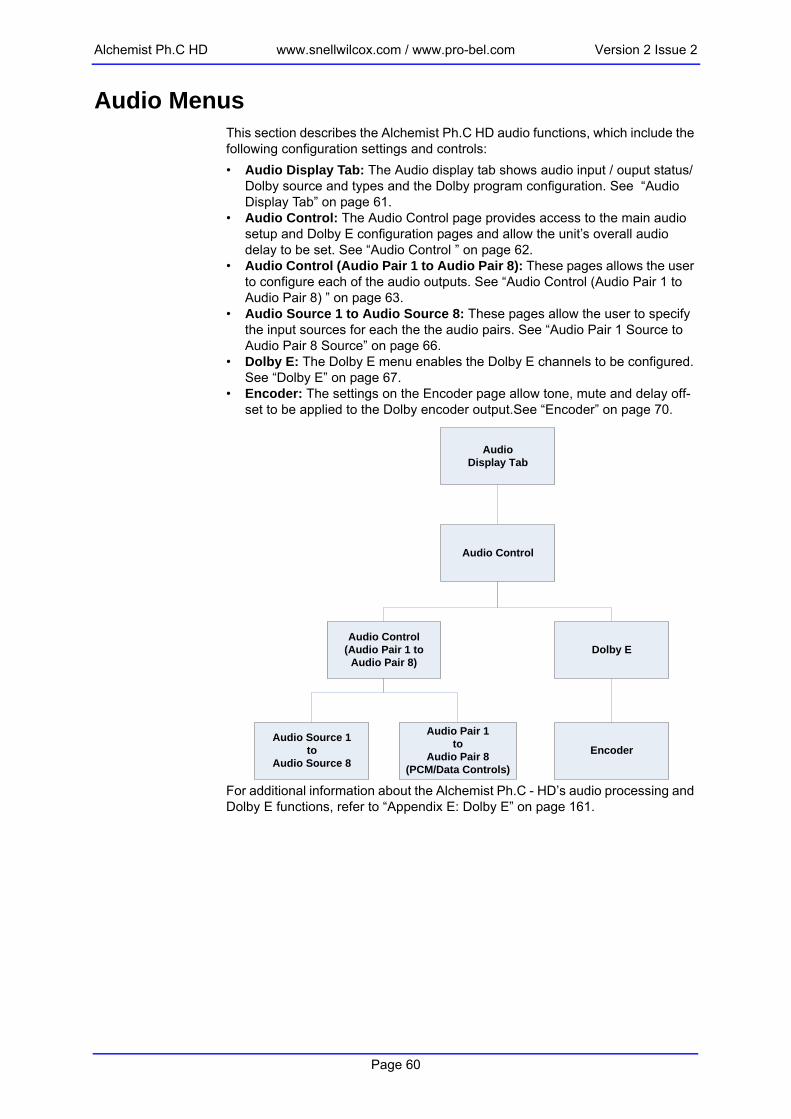
Alchemist Ph.C HD www.snellwilcox.com / www.pro-bel.com Version 2 Issue 2
Audio MenusThis section describes the Alchemist Ph.C HD audio functions, which include the following configuration settings and controls:• Audio Display Tab: The Audio display tab shows audio input / ouput status/
Dolby source and types and the Dolby program configuration. See “Audio Display Tab” on page 61.
• Audio Control: The Audio Control page provides access to the main audio setup and Dolby E configuration pages and allow the unit’s overall audio delay to be set. See “Audio Control ” on page 62.
• Audio Control (Audio Pair 1 to Audio Pair 8): These pages allows the user to configure each of the audio outputs. See “Audio Control (Audio Pair 1 to Audio Pair 8) ” on page 63.
• Audio Source 1 to Audio Source 8: These pages allow the user to specify the input sources for each the the audio pairs. See “Audio Pair 1 Source to Audio Pair 8 Source” on page 66.
• Dolby E: The Dolby E menu enables the Dolby E channels to be configured. See “Dolby E” on page 67.
• Encoder: The settings on the Encoder page allow tone, mute and delay off-set to be applied to the Dolby encoder output.See “Encoder” on page 70.
For additional information about the Alchemist Ph.C - HD’s audio processing and Dolby E functions, refer to “Appendix E: Dolby E” on page 161.
AudioDisplay Tab
Audio Control
Audio Control(Audio Pair 1 to
Audio Pair 8)Dolby E
Audio Source 1to
Audio Source 8
Audio Pair 1to
Audio Pair 8(PCM/Data Controls)
Encoder
Page 60

Version 2 Issue 2 www.snellwilcox.com / www.pro-bel.com Alchemist Ph.C HD
Audio Display TabThe Audio display tab on the Home screen illustrates Audio Input / Audio Output status, Dolby sources and types and the Dolby program configuration.
EMB In The EMB In indicators display the EMB input status.• Green indicates that a valid embedded input signal is
present.• Red indicates that no embedded input signal is pres-
ent.
AES In The AES In indicators display the AES input status.• Green indicates that a valid AES input signal is pres-
ent.• Red indicates that no AES input signal is present.
Out Src These indicators display the audio output pair status.• The text for each describes the selected source cur-
rently routed to each output.• Green indicates that the selected source is valid.• Red indicates that the selected source is not valid.
Dolby 1 / Dolby 2 Source
This indicates the input source that is routed to the respective Dolby channel decoder.• Green indicates a valid Dolby E or Dolby D signal• Yellow indicates a valid PCM signal• Red indicates that no Dolby E, Dolby D or PCM signal
is present.
Dolby 1 / Dolby 2 Source Type
This indicates the bitstream format that is being routed to the respective Dolby channel decoder.• Green indicates a valid Dolby E or Dolby D signal.• Red indicates that there is no valid Dolby E or Dolby D
signal.• Yellow indicates a valid PCM signal.
Dolby 1 / Dolby 2 Configuration
This displays the Dolby program configuration being routed to the respective Dolby channel decoder.
Page 61

Alchemist Ph.C HD www.snellwilcox.com / www.pro-bel.com Version 2 Issue 2
Audio Control The Audio Control page is accessed by touching anywhere on the audio tab.
Audio Delay Offset
This allows the overall audio delay of the unit to be set. This value will be displayed on the Audio Channel Control screens.
Any audio delay added to individual PCM or Dolby channels is added to this delay.
Control Touch the Control button to access the audio control pages from which the Alchemist’s audio setup can be configured.
Dolby E Touch Dolby E to access the Dolby E setup page.
Note:
Page 62

Version 2 Issue 2 www.snellwilcox.com / www.pro-bel.com Alchemist Ph.C HD
Audio Control (Audio Pair 1 to Audio Pair 8) This page allows the user to configure each of the audio outputs.
For each of the Alchemist Ph.C – HD’s eight audio pairs the following information is shown.
Source This displays the source that has been configured for each of the output audio pairs. If the source is present and valid, it is displayed in green. If the source is absent, or invalid. it is displayed in red.
Type In the absence of Dolby E output, this displays whether the output is AES audio or data.
Gain If the Gain indicator is yellow, the gain on the channel has been changed from the default setting. This indicator applies only to PCM.
Page 63

Alchemist Ph.C HD www.snellwilcox.com / www.pro-bel.com Version 2 Issue 2
Touch Source/Type to specify the input source and type.Touch Gain/Delay/Tone to adjust the channel gain and delay options.
Audio Pair 1 to Audio Pair 8 (PCM/Data Controls)The settings on the Audio Control pages enable the channel gain, delay, Tone, Mute and Mono options to be adjusted.These settings are only applicable to PCM audio / Data only. Dolby E tone and gain options are configured from the Dolby E pages.
Delay If the Delay indicator is yellow, the Delay on the channel has been changed from the default setting. This indicator applies only to PCM / Data signals.Note that this differs from the global audio delay offset, applied to all channels, that is adjusted on the Audio Control page.
Tone If the Tone indicator is yellow, the output channel is currently producing a tone. This indicator applies only to PCM / Data signals.
Gain This allows the gain of the left and right channels of the pair to be adjusted. The range of control is ±12 dB.Touch Reset to return the gain control to its preset value of 0 dB.
Page 64

Version 2 Issue 2 www.snellwilcox.com / www.pro-bel.com Alchemist Ph.C HD
Mono Touch the Mono button to take an average of the left and right channels and apply that average to both.
Mute When selected, both channels will be muted.
Tone Touch tone to generate the tone specified in the Tone Type section.
Tone Type The audio pair may be assigned a fixed frequency tone. To change the tone type, touch Select and in the dialog that appears, select the tone type.
Pair Audio Delay(PCM/Data Audio Only)
The audio delay for each pair can be adjusted individually. This delay is added to the global audio delay and the unit’s internal processing delay. The total delay for the pair is displayed in the Total field. The values of this delay vary according to the conversion being made and are listed in the “Latency Tables” appendix of the Alchemist Ph.C – HD Operator’s manual.To change the delay offset for the audio pair, use the slider bar.Note: the system latency is dependent on the following user controls - input standard, output standard, FilmTools, Min Delay and Synchro Timecode conversion.In Timecode synchro mode, the system delay can change by a maximum of one output standard frame. The modified system delay is displayed on the Home page.
Page 65

Alchemist Ph.C HD www.snellwilcox.com / www.pro-bel.com Version 2 Issue 2
Audio Pair 1 Source to Audio Pair 8 SourceThe settings on these pages enable the input source for any of the eight audio output pairs to be specified.
Inputs that have a valid source present are displayed in green. Inputs that do not a have a valid source present are displayed in red. When selected as the input for the audio pair, the source is illuminated.To select the audio type, touch PCM or Data. These options are not available if a Dolby source has been specified.
Page 66

Version 2 Issue 2 www.snellwilcox.com / www.pro-bel.com Alchemist Ph.C HD
Dolby EThe Dolby E menu enables the Dolby E channels to be configured. Each channel consists of a dedicated Dolby E encoder and decoder module. The Dolby E page is divided in two. The top half of the page contains the controls for Dolby channel 1 and the bottom half of the page contains the controls for Dolby channel 2.
Source This displays the input on which the Dolby E input stream is present. It can be present on either AES pairs 1 to 8, or on Embedded pairs 1 to 8.To specify a different input source, touch Select.
IP Alignment This displays the Dolby E input alignment, which can be:• Advanced by one input frame.• Co-timed with the video signal.• Delayed by one input frame.To change the input alignment, touch Select.The input alignment needs to be selected based upon what devices are upstream from the Alchemist.
Decoder Input This displays the input to the Dolby decoder channel, the Dolby E/D program configuration and associated bit depth.
Page 67

Alchemist Ph.C HD www.snellwilcox.com / www.pro-bel.com Version 2 Issue 2
Monitor The Monitor function enables a predefined method of operation in which decoded audio pairs are automatically assigned to specific AES outputs, thus maintaining program configuration. No change is made to the embedded output mapping, and the mapped AES outputs will not be subjected to any audio gain or delay processing. This control overrides any other mapping to the relevant 4 AES outputs.In this mode:• Dolby E Bitstream 1 will always be decoded to AES
outputs 1 to 4.• Dolby E Bitstream 2 will always be decoded to AES
outputs 5 to 8.Both outputs will adopt the same structure and configuration as the Dolby E.For example, if Dolby E Bitstream 1 and 2 both have a 5.1 + 2 program configuration, the output on the AES BNC outputs would be structured as shown in the diagram below.
1 2 3 4 5 6 7 8
Dolby Bitstream 1 Dolby Bitstream 2
Bitstream 1 Pair 1L/R
Bitstream 1 Pair 2C/LFE
Bitstream 1 Pair 3Ls/Rs
Bitstream 1 Pair 4Lt/Rt
Bitstream 2 Pair 1L/R
Bitstream 2 Pair 2C/LFE
Bitstream 2 Pair 3Ls/Rs
Bitstream 2 Pair 4Lt/Rt
AES OUTPUTS
AES BNC’s
Encoder Output This displays the output from the Dolby encoder channel, the Dolby E program configuration and associated bit depth.Touch this control to access the Encoder options page, on which a tone for the Dolby channel can be configured and applied, a mute can be applied to the channel, and the channel delay offset can be specified. See page 70 for more information.
Page 68

Version 2 Issue 2 www.snellwilcox.com / www.pro-bel.com Alchemist Ph.C HD
Map Decode The Map Decode function enables a predefined mode of operation in which decoded audio pairs will be automatically assigned to specific embedded and AES channels, thus maintaining program configuration.This mapping for the embedded outputs will override any other mapping to these 4 embedded outputs. The AES mappings can be overridden by the Decoder Monitor function.In this mode:• Dolby E Bitstream 1 will always be decoded and
embedded on channels 1 to 4.• Dolby E Bitstream 2 will always be decoded and
embedded on channels 5 to 8.Both outputs will adopt the same structure and configuration as the Dolby E.For example, if Dolby E Bitstream 1 and 2 both have a 5.1 + 2 program configuration, the output embedded within the SDI will be structured as follows.
1 2 3 4 5 6 7 8
Dolby Bitstream 1 Dolby Bitstream 2
Bitstream 1 Pair 1L/R
Bitstream 1 Pair 2C/LFE
Bitstream 1 Pair 3Ls/Rs
Bitstream 1 Pair 4Lt/Rt
Bitstream 2 Pair 1L/R
Bitstream 2 Pair 2C/LFE
Bitstream 2 Pair 3Ls/Rs
Bitstream 2 Pair 4Lt/Rt
Embedded OUTPUTS
Embedded Pairs
OP Alignment This displays the Dolby E output alignment, which can be:• Advanced by one output frame.• Co-timed with the video signal.• Delayed by one output frame.To change the output alignment, touch Select.The output alignment needs to be selected based upon what devices are downstream from the Alchemist.
Page 69

Alchemist Ph.C HD www.snellwilcox.com / www.pro-bel.com Version 2 Issue 2
EncoderThe settings on the Encoder page allow tone, mute and delay offset to be applied to the Dolby encoder output.
Tone Type The Dolby encoder may be assigned a fixed frequency tone. To change the tone type, touch Select and in the dialog that appears, select the tone type.Note: Program configuration and Metadata follow the input to the decoder. Any program configuration which utilizes a .1 / LFE channel will contain a 100Hz test tone when the Tone is activated.
Tone Touch Tone to generate the tone specified in the Tone Type section.
Mute Touch Mute to apply a mute to the Dolby encoder output.
Delay Offset The audio delay for each Dolby encoder channel can be adjusted individually. The total delay for the pair is displayed in the Total field and is the sum of:System Delay + Dolby Input Alignment + Dolby Output Alignment + Master (Global) Delay + Individual Channel Delay (configured here).The values of the system delay vary according to the conversion being made and are listed in the “Latency Tables” appendix of the Alchemist Ph.C – HD Operator’s manual.To change the delay offset for the audio pair, use the slider bar.
Page 70

Version 2 Issue 2 www.snellwilcox.com / www.pro-bel.com Alchemist Ph.C HD
Timecode MenusThis section describes the Alchemist Ph.C HD timecode functions, which include the following displays, configuration settings and controls:• Timecode Display: Timecode information is displayed on the Timecode tab
in the lower right of the Home screen. See “Timecode Display” on page 72.• Timecode I/O: Use these settings to settings to setup input timecode sources
and output timecodes. See “Timecode Setup” on page 73.• Timecode Control: Use these settings to specify timecode input triggers,
output loads, prerun times and the timecode mode. See “Timecode Control” on page 76.
For additional information about timecodes, refer to “Appendix B: Timecode” on page 111.
The Alchemist Ph.C Timecode functions are optional. If the Timecode option has not been purchased, these functions are not available.
Note:
Timecode
Timecode Display Timecode I /O Timecode Control
Input Timecode
Timecode Entry
Input Trigger
Output A /B Load
Prerun
Output A /B Timecode
Timecode Mode
Input Timecode Setup
Output Timecode Setup
Page 71

Alchemist Ph.C HD www.snellwilcox.com / www.pro-bel.com Version 2 Issue 2
Timecode DisplayThe Timecode display tab on the Home screen displays the current input and output timecodes, the selected timecode mode and synchro status of the unit, and provides access to the Timecode Setup and Timecode Control menus.
Input Timecode
This displays the current timecode from the specified timecode source.
Output Timecode A & B
These fields display the timecodes currently being generated for outputs A and B respectively.
DF / NDF These indicators show whether the corresponding timecode is a drop frame or non-drop frame.• When DF is illuminated, the timecode is drop frame.• When NDF is illuminated, the timecode is non-drop
frame.• When neither is illuminated, the principle of drop frame /
non-drop frame is not applicable.
Timecode Mode
This field displays the currently selected timecode mode.
Synchro Status
This field displays the current status of timecode synchronization. For example:• Prerun indicates that the timecode is in the prerun phase
preceding a synchro start event.• Success indicates that the synchro start event has
occurred successfully.
Setup Touch the Setup button to access the Timecode Setup menu.
Control Touch the Control button to access the Timecode control menu.
Page 72

Version 2 Issue 2 www.snellwilcox.com / www.pro-bel.com Alchemist Ph.C HD
Timecode SetupWhen Setup is selected, the screen shown below is displayed. The controls on this screen allow timecode input sources and outputs to be configured.
Page 73

Alchemist Ph.C HD www.snellwilcox.com / www.pro-bel.com Version 2 Issue 2
Input Timecode Setup
Output Timecode SetupOutputs A and B can be configured independently and have separate controls, allowing different timecode values to be displayed. However, the Timecode mode is always common to Output A and Output B.
SD Source These options specify the source of SD timecode input.VITC: The SD input video timecode is read from the VITC signals. (SMPTE 12M/SMPTE 266M)LTC: The SD input video timecode is read from the Longitudinal Timecode Connector (LTC). (SMPTE 12M)
HD Source These options specify the source of the HD timecode input.Emb VITC: The HD input video timecode is read from the embedded VITC signals. (SMPTE RP188)EMB LTC: The HD input video timecode is read from the embedded LTC signals. (SMPTE RP 188)LTC: The HD input video timecode is read from the LTC connector. (SMPTE 12M)
Frame Count This option specifies the maximum frame number the input timecode will reach before it resets to zero. This information is essential for timecode arithmetic.Detect: Measures the frame count max from the input timecode.Format: Assumes that the timecode was generated to match the frame rate of the video.24/25/30: Forces the input frame count max to the specified setting. This allows material that may have been generated with the wrong frame count max limit (for example, slow PAL) to be accommodated.
Both outputs will adopt the same configuration for Timecode Mode.
Frame Count (Output A & B)
These options specify the maximum number the output timecode frame will reach before it resets to zero.Auto: Assumes that the timecode is generated to match the specified frame rate of the output video.24/25/30: Forces the output frame count max to the specified setting. This allows the user to pre-compensate for later changes in playback speed, of the material generated by the Alchemist. Slow PAL for example.
Note:
Page 74

Version 2 Issue 2 www.snellwilcox.com / www.pro-bel.com Alchemist Ph.C HD
Drop Frame Mode (Output A & B)
This setting is only relevant to 59.94Hz output.When enabled, the first two frame numbers (00 and 01) are omitted from the count at the start of each minute, except minutes 00, 10, 20, 30, 40, and 50.Note that if the Alchemist is configured to E-E timecode mode, and is performing 30 fps – 30 fps timecode conversion, the output drop/non-drop type follows the input. For example, 59.94Hz DF input will automatically give a 59.94Hz DF output and vice versa.On: Forces the output timecode to be drop frame. On can only be selected if the output timecode is 30 fps.Off: Forces the output timecode to be non-drop frame. Off can only be selected if the output timecode is 30 fps.
SD VITC Insertion Line
This specifies, for an SD output, which line of vertical blanking the first insertion of VITC signal occurs on. If enabled, the second insertion will occur two lines below.625 Default: Lines 19/332 and 21/334 (SMPTE 266M)525 Default: Lines 14/277 and 16/279 (SMPTE 266M and RP164)625 Range: Between lines 6/319 and 20/333 (SMTPE 12M and SMPTE 266M)525 Range: Between lines 10/273 and 17/280 (SMPTE 12M and SMPTE 266M)Note that the range refers to the first insertion line, not the second.
SD Activate This option enables/disables the timecode output format for SD output. The options are VITC or RepeatNote that the LTC via XLR is always enabled.
HD Activate This option enables/disables the timecode output format for HD output. The options are Emb VITC or EMB LTCNote that the LTC via XLR is always enabled.
Page 75

Alchemist Ph.C HD www.snellwilcox.com / www.pro-bel.com Version 2 Issue 2
Timecode ControlWhen Timecode Control is selected, the screen shown below is displayed.
Input TimecodeThis displays the input timecode read from the specified source.Drop Frame will be illuminated when a drop frame timecode is detected on the source timecode.
Timecode EntryThis option allows the desired timecode value to be entered. Preset values of 10h 00m 00s 00f and 01h 00m 00s 00f are available.
Input TriggerThe input trigger is the value of the source timecode that will cause an output timecode event to occur.To specify the timecode at which the trigger event will occur, do one of the following:• Using the Timecode Entry keypad, enter a new timecode, and then touch the
Set button next to the Input Trigger box.• Touch the Input TC button next to the Input Trigger box. This sets the time-
code to the input timecode value.
Output A LoadThis specifies the value that will be inserted in the output A timecode when the input trigger event occurs.To specify a new timecode value, do one of the following:
Page 76

Version 2 Issue 2 www.snellwilcox.com / www.pro-bel.com Alchemist Ph.C HD
• Using the Timecode Entry keypad, enter a new timecode, and then touch the Set button next to the Output A Load box.
• Touch the Input TC button next to the Output A Load box. This sets the time-code to the input timecode value.
Output B LoadThis specifies the value that will be inserted in the Output B timecode when the input trigger event occurs. This setting is independent of Output A; however, both outputs will adopt the same Timecode Mode.To specify a new timecode value, do one of the following:• Using the Timecode Entry keypad, enter a new timecode, and then touch the
Set button next to the Output B Load box.• Touch the Input TC button next to the Output B Load box. This sets the time-
code to the input timecode value.
PrerunThis control is only used when performing a Synchro Prerun timecode conversion. It specifies the amount of time before the input trigger that the user would like continuous timecode output.To specify a new prerun value, do one of the following:• Using the Timecode Entry keypad, enter a new timecode, and then touch the
Set button next to the Prerun box.• Touch the Preset button next to the Prerun box. This sets the value to the
default value of 00h 03m 00s 00f.
Output A TimecodeThis displays the current value of the timecode being generated for Output A, as specified by the Timecode mode. If configured to be drop frame, the Drop Frame indicator is illuminated.
Output B TimecodeThis displays the current value of the timecode being generated for Output B, as specified by the Timecode mode. If configured to be drop frame, the Drop Frame indicator is illuminated.
Timecode ModeThis control selects the timecode mode to be used by the Alchemist. For descriptions of each mode, refer to “Appendix B: Timecode” on page 111.The available timecode modes are:• Synchro Auto• Synchro Prerun• Synchro Manual• E-E• E-E Regen• Freerun• Trigger Load
The output LTC XLR connector will always deliver Output A timecode.Note:
Page 77

Alchemist Ph.C HD www.snellwilcox.com / www.pro-bel.com Version 2 Issue 2
Timecode Control WarningsThe timecode displays for the Input Trigger, Output Loads, and Prerun change color to indicate valid or invalid values.
Green Indicates that the value is valid, and that the corresponding event will occur when the specified timecode is reached.
Yellow Indicates that the value is not currently valid, but if certain conditions, such as the input standard or timecode type change, the corresponding event may occur.For example, if the Input Trigger timecode is set to occur on a frame that does not exist in the current input standard, the value appears in yellow. However; if before the Input Trigger timecode is reached, the input standard changes to one in which the specified frame occurs, the input trigger event will occur.
Red The specified value is not valid, and will not be so under any circumstances.
Page 78

Version 2 Issue 2 www.snellwilcox.com / www.pro-bel.com Alchemist Ph.C HD
FilmToolsThis section describes the Alchemist Ph.C HD FilmTools functions, which include the following controls:• Input Cadence: Use this menu to define the film cadence of the incoming
content. See “FilmTools Input” on page 81.• Output Cadence: Use this menu to control the cadence of the converted
content. See “FilmTools Output” on page 86.• Control: Use this menu to specify user-specified FilmTools control options.
See “FilmTools Control” on page 90.• Detection: Use this menu to control the bias and internal detection algorithm.
See “FilmTools Detection” on page 91.
For more information, see “Appendix D: FilmTools” on page 133.
The Alchemist Ph.C FilmTools functions are optional. If the FilmTools option has not been purchased, these functions are not available.
Note:
Film Tools
Input Output Control Detection
Page 79

Alchemist Ph.C HD www.snellwilcox.com / www.pro-bel.com Version 2 Issue 2
Enabling FilmToolsThe FilmTools option is enabled and disabled from the Conversion menu.
Page 80

Version 2 Issue 2 www.snellwilcox.com / www.pro-bel.com Alchemist Ph.C HD
FilmTools Input The Input Cadence menu allows the user to define a film cadence for the incoming content. A single continuous and perfect cadence can be defined flawlessly by its relationship to timecode, or by aligning an internal free-running cadence generator. If the content contains discontinuous or mixed cadence, or if the cadence is unknown before conversion, the Detect mode performs real-time analysis to assign cadence.
To select the Cadence Mode, in the Cadence Control section, touch the Select button. Then, from the Select Cadence Mode dialog, choose the required cadence.
Page 81

Alchemist Ph.C HD www.snellwilcox.com / www.pro-bel.com Version 2 Issue 2
AutoCadence is defined by the internal sequence detector unless a PsF input standard has been selected, in which case perfect frame segmentation is assumed (i.e. 2:2 F1/2)This is the default selection.
DetectCadence is defined by the internal sequence detector (even when PsF inputs are selected).
1:1Incoming content is interpreted as 1:1 cadence (field by field or frame by frame motion).
2:2 F1/2 (PsF)All incoming content is interpreted as 2:2 F1/2 (PsF) cadence.
2:2 F2/1All incoming content is interpreted as 2:2 F2/1 cadence.
2:3 TC DatumIncoming content is interpreted as continuous 2:3 cadence derived from continuous input timecode by identifying the specific 2:3 frame type and timecode of an input 'Datum' frameFor more information, refer to “Appendix D: FilmTools” on page 133..
2:3 Datum CadenceThis control defines the 2:3 cadence of the Datum frame when the input cadence control is 2:3 TC Datum mode. For more information, see “Understanding 2:3 Datum Cadence” on page 156.
Page 82

Version 2 Issue 2 www.snellwilcox.com / www.pro-bel.com Alchemist Ph.C HD
2:3 Cadence Reset
2:3 Datum Timecode
Max Time Pre-Datum
On Valid TC (Default)
Input 2:3 cadence will be defined according to the 2:3 Datum Cadence and Timecode controls when stable input timecode has been detected. The input timecode may be greater or less than specified 2:3 Datum Timecode.
At Datum Input 2:3 cadence will be defined according to the 2:3 Datum Cadence and Timecode controls. The cadence reset occurs when the input timecode is equal to the 2:3 Datum Timecode.
Input Timecode Trigger (Default)
(Default) The 2:3 Datum Timecode is automatically set to match the timecode “Input Trigger” value.
Independent Cadence Trigger
The 2:3 Datum Timecode can be set to any required frame.
0 – 23 hours(Default12 hours)
Defines the start of the Cadence Window. Only applicable when 2:3 Cadence Reset is set to “On Valid TC”. For more information, “Understanding Datum TC Conversion” on page 154.
Page 83

Alchemist Ph.C HD www.snellwilcox.com / www.pro-bel.com Version 2 Issue 2
2:3 TC 0 and 5Incoming content is interpreted as continuous 2:3 cadence defined by a specific relationship to the frame count of non-drop frame input timecode.
0 and 5 CadenceThis control defines the phase of the relationship between frame count and input timecode. When frame count values of 0 and 5 are present, the 2:3 cadence is interpreted as the selected frame type.For more information, see “Understanding 2:3 Datum Cadence” on page 156.
Page 84

Version 2 Issue 2 www.snellwilcox.com / www.pro-bel.com Alchemist Ph.C HD
2:3 FreerunIncoming content is interpreted as continuous 2:3 cadence derived from an internal free-running 2:3 cadence generator.
Cadence OffsetThis control enables the cadence of the free-running 2:3 cadence generator to be offset.
Page 85

Alchemist Ph.C HD www.snellwilcox.com / www.pro-bel.com Version 2 Issue 2
FilmTools Output The FilmTools Output Cadence Control menu enables the user to control the cadence of the converted content. This menu allows the user to select the required cadence including any required relationship with the output timecode.
OffNo specific cadence will be forced. Outgoing content will follow the Input (field by field or frame by frame motion).
2:2 F1/2 (PsF)Outgoing content is generated with 2:2 F1/2 (PsF) cadence.
2:2 F2/1Outgoing content is generated with 2:2 F2/1 cadence.
Page 86

Version 2 Issue 2 www.snellwilcox.com / www.pro-bel.com Alchemist Ph.C HD
2:3 TC DatumOutgoing content is generated with continuous 2:3 cadence derived from continuous output timecode by identifying the specific 2:3 frame type and timecode of an output ‘Datum’ frame.
2:3 Datum CadenceThis control defines the 2:3 cadence of the Datum frame when the input cadence control is 2:3 TC Datum mode.2:3 Cadence Reset
On Valid TC(Default)
Output 2:3 cadence will be defined according to the 2:3 Datum Cadence and Timecode controls when stable output timecode has been detected. The output timecode may be greater or less than specified 2:3 Datum Timecode.
At Datum Output 2:3 cadence will be defined according to the 2:3 Datum Cadence and Timecode controls. The cadence reset occurs when output timecode is equal to the 2:3 Datum Timecode
Page 87

Alchemist Ph.C HD www.snellwilcox.com / www.pro-bel.com Version 2 Issue 2
2:3 Datum Timecode
Max time pre-datumThis control defines the start of the Cadence Window. It is only applicable when 2:3 Cadence Reset is set to “on valid TC”. The default value is 12 hours.
2:3 TC 0 and 5Outgoing content is generated with continuous 2:3 cadence defined by a specific relationship to the frame count of non-drop frame output timecode.
0 and 5 CadenceThis control defines the phase of the relationship between frame count and output timecode. When frame count values of 0 and 5 are present, the 2:3 cadence is interpreted as the selected frame type.
Output Load A Timecode (Default)
The 2:3 Datum Timecode is automatically set to match the “Output A Load” timecode.
Independent Cadence Trigger
The 2:3 Datum Timecode can be set to any required frame.
Page 88

Version 2 Issue 2 www.snellwilcox.com / www.pro-bel.com Alchemist Ph.C HD
2:3 FreerunOutgoing content is generated with continuous 2:3 cadence derived from an internal free-running 2:3 cadence generator.
Cadence OffsetThis control enables the cadence of the free-running 2:3 cadence generator to be offset.
Page 89

Alchemist Ph.C HD www.snellwilcox.com / www.pro-bel.com Version 2 Issue 2
FilmTools Control The FilmTools Control menu enables the FilmTools Mode and Film Aperture settings to be specified.
Mode
Film Aperture
Auto(Default)
Selects between synchronized or interpolated conversion as appropriate depending on the input and output formats specified. See “Conversion Tables” on page 151. Interpolation gives the smoothest motion profile. Synchronize disables temporal interpolation and maintains clean frames. Note synchronize mode can cause field/frame drops or repeats depending on the input and output frequencies selected.
Synchronize Forces the conversion by synchronization.
Interpolation Forces the conversion by interpolation.
Normal(Default)
This aperture maximizes the vertical resolution from the incoming film material. This is the optimum aperture for most applications.
Sharp This aperture maintains maximum possible vertical resolution with the result that it is less tolerant to film sequence detection errors
Safe This aperture is film safe. It is the most tolerant to film sequence detection errors. Note this mode is useful in applications where the film content contains mixed cadence regions.
Page 90

Version 2 Issue 2 www.snellwilcox.com / www.pro-bel.com Alchemist Ph.C HD
FilmTools Detection The FilmTools Detection menu controls the internal sequence detection algorithm.The Alchemist utilizes a complex integrated detection algorithm to identify content type and cadence information. This algorithm has been optimized so that the maximum possible range of material can be converted in a single pass. In some rare cases it may be desirable to bias the algorithm using the following controls.
Video Enable
On(default)
Allows the sequence detector to positively identify content as 1:1 (video).
Off The sequence detector will never identify content as video.
Page 91

Alchemist Ph.C HD www.snellwilcox.com / www.pro-bel.com Version 2 Issue 2
Film Enable
Bias
Window ControlThis control allows the sequence and cut detection to be restricted to specific areas of the image. A typical detection application would be to avoid sequence detection errors caused by artifacts near the images edges. A typical cut detection application would be to prevent the detection of cuts occurring within a specific region of the image.
Any (Default) Allows the sequence detector to identify film of any cadence. This maybe 2:2, 2:3, discontinuous 2:3, orphan fields, varispeed or animation.
2:2 Forces the sequence detection to identify film content as 2:2 cadence only. Content maybe F1/2 or F2/1.
2:3 Forces the sequence detection to identify film content as 2:3 cadence only. The 2:3 cadence may be discontinuous.
Animation Optimized sequence detection algorithm specifically for animation.
Off The sequence detector will not identify content as film.
Normal(Default)
This is the optimum setting for most applications. The detection algorithms have been optimized to give the most accurate results for the greatest possible range of material.
Video 2,Video 1,Film 1,Film 2
In some rare cases in may be desirable to bias the sequence detector such that it is more likely to detect video or more likely to detect film. Video 2 biases more strongly towards video than Video 1. Similarly Film 2 biases more strongly towards film than Film 1.
Auto(Default)
The sequence/cut detection region will be set to default values.
Track Input Blanking
The sequence/cut detection region will track with the settings for input blanking.
User The user may manually define a specific sequence/cut detection region.
Page 92

Version 2 Issue 2 www.snellwilcox.com / www.pro-bel.com Alchemist Ph.C HD
Window OverlayThe overlay permits adjustment of the active sequence/cut detection region.
User Window
Off(Darken)
The sequence/cut detection region overlay is disabled.
Darken The active sequence/cut detection region is shown with reduced luminance.
Greyed The active sequence/cut detection region is shown in mono
Left0%-100%(Default 1%)
Defines the left edge of the detection region as a percentage of the picture width.
Right0%-100%(Default 99%)
Defines the right edge of the detection region as a percentage of the picture width.
Top0%-100%(Default 1%)
Defines the top edge of the detection region as a percentage of the picture height.
Bottom0%-100%(Default 99%)
Defines the bottom edge of the detection region as a percentage of the picture height.
Page 93

Alchemist Ph.C HD www.snellwilcox.com / www.pro-bel.com Version 2 Issue 2
StatusThe Status area provides information about the status of the unit.
MessagesThis area displays the following messages about the state of the Alchemist Ph.C HD:
If there is more than one message to be displayed, the display will cycle through them continuously.
Booting The unit is starting up.
System OK The unit is functioning normally.
Fan Fail The main cooling fan, at the rear of the unit, has failed. This condition may cause the unit to overheat.
Diagnostics Active
One of the diagnostic tests, available on the Diagnostics screen is currently running.
System Overheating
The unit’s temperature is higher than recommended. If the temperature continues to rise, the unit will shut down critical cards and the display screen will go blank. However, the fans will continue running to cool the unit. After the unit has cooled sufficiently, it may be restarted.
PSU Fault A problem has been detected with one of the power supply units.Note that on units fitted with two power supplies, if one supply is turned on but the other is not, a PSU fault will be reported.
Version Unknown
The combination of components comprising the Alchemist Ph.C. is not recognized.
Page 94

Version 2 Issue 2 www.snellwilcox.com / www.pro-bel.com Alchemist Ph.C HD
System FunctionsThis section describes the Alchemist Ph.C HD system functions, which include the following configuration settings and controls:• RollCall: Use these settings to specify the Alchemist Ph.C’s RollCall
information, set up RollTracks, and specify what information should be logged. See “RollCall” on page 96.
• Ethernet: Use the Ethernet controls to specify whether the unit receives its IP address dynamically or, if it does not, to specify the unit’s IP address. See “Ethernet” on page 99.
• Panel Controls: Use these settings to calibrate to touch screen, temporarily de-activate the touch screen so that it can be cleaned, and specify panel timeout settings. See “Panel Controls” on page 99.
• Setup: Use these settings to enable or disable shaped horizontal blanking, active line length type, and analog blanking. See “Setup” on page 101.
• Info: The system information screen displays version information about the Alchemist Ph.C. See “Info” on page 102.
• Debug: Use the Tools menu to access the Timecode Overlays screen, and the Diagnostics screen to perform diagnostic tests on the Alchemist Ph.C. See “Debug” on page 103.
System
RollCall Ethernet Panel Controls Setup Info
Tools
Debug
Diagnositcs
Timecode Overlays
Page 95

Alchemist Ph.C HD www.snellwilcox.com / www.pro-bel.com Version 2 Issue 2
RollCallThese controls allow information to be sent, via the RollCall™ network, to other compatible units connected on the same network.
Unit IDThis item allows the address of the unit to be set.To change the ID, do one of the following:• Use the scroll bars to scroll through the list of addresses (in Hex). The range
is from 10 to FF. • Select the ID box, use the keypad to enter the new address and then select
OK.
Name This allows the name of the unit as it appears on the RollCall network, to be changed.To change the name select the Edit item and use the keyboard to edit the text. Select OK to enable the new name.
Log Server nameThis allows the name of the Logging server on the RollCall network, to be changed in a similar manner to that described above.
Page 96

Version 2 Issue 2 www.snellwilcox.com / www.pro-bel.com Alchemist Ph.C HD
RollTracksWhen RollTracks is selected, the screen shown below is displayed.
The RollTrack function allows the Alchemist to automatically control remote audio delay modules using the RollCall system. As the delay through the Alchemist varies according to the conversion mode, delay modules connected via the RollTrack system will automatically have their delay updated to match. The delay sent out via the RollTrack system matches the internal audio delay of the Alchemist. For more detailed information, see “Appendix G: RollTrack Audio Delay Tracking” on page 189.The destination for the delay information is set from the RollTrack address as follows:Up to 6 audio delays may be selected as a destination. Selecting any of the six Address edit buttons produces an address editing keyboard.The string characteristics of a RollCall address are:
0000:00:00x00x00 The first set of digits identifies the network address, in hexadecimal.
This is usually 0000.
0000:00:00x00x00 The second set of digits identifies the enclosure address, in hexadecimal.
0000:00:00x00x00 The third set of digits identifies the slot address of the delay module, in hexadecimal.
0000:00:00x00x00 The fourth set of digits identifies the connection or channel number, in decimal.
0000:00:00x00x00 The last set of digits identifies the unit ID, in decimal.
Page 97

Alchemist Ph.C HD www.snellwilcox.com / www.pro-bel.com Version 2 Issue 2
A more detailed description of these items is given in the RollTrack section (Appendix) at the end of this manual.In a typical set-up, the network address will be 0000, the enclosure and slot address would match those of the destination module, and the channel number would be one of 14,15,16 or 17 and the unit ID should be set to the RollCall ID of the destination unit.The Alchemist RollTrack output becomes active as soon as the enclosure address is set to be non zero and OK selected.
Log ItemsWhen Log Items is selected, the screen shown below is displayed.
This screen reveals a list of items that can be made available for logging.
Input Status
When checked, a loss of input signal condition will be indicated to the logging device.
Input Standard
When checked, the current input standard will be available to the logging device.
Reference Status
When checked, a loss of reference signal condition will be indicated to the logging device.
Output Standard A & B
When checked, the current output standard will be available to the logging device.
System Status
When checked, system status log events will be available to the logging device.
Page 98

Version 2 Issue 2 www.snellwilcox.com / www.pro-bel.com Alchemist Ph.C HD
EthernetThe Alchemist Ph.C can connect to a RollCall 32-bit control panel via an Ethernet connection. The unit’s IP address can either be dynamically assigned by a DHCP server, or manually assigned.Use the Ethernet controls to specify whether the unit receives its IP dynamically (using DHCP) or, if it does not, to specify the unit’s IP address.
To use a dynamically assigned IP address, in the DHCP section, select Enable. The Alchemist Ph.C HD will receive its IP address from a DHCP server, and its address will be displayed in the Current Address information display.To manually assign an IP address, in the DHCP section, touch Disable, then in the Address section, touch Edit. Use the keyboard to enter the IP address, and then touch OK.
Panel ControlsWhen Panel Controls is selected, the screen shown below is displayed.
Page 99

Alchemist Ph.C HD www.snellwilcox.com / www.pro-bel.com Version 2 Issue 2
CalibrateThis function allows re-calibration of the touch screen.Press on the cursor area for a few seconds and the next screen will appear.The calibration process will be completed when the Calibration Successful dialog appears on the screen as shown below.Touch the screen anywhere to return to the System screen.
CleanThis allows the screen to be cleaned without activating any functions.When the Clean function is enabled a representation of a countdown timer will appear on the screen. This timer will be reset to zero whenever the screen is touched during the cleaning process and will run for approximately 16 seconds after the last time the screen was touched; it will then return to the System screen.
Panel TimeoutIf the touch screen has not been used for a certain period of time it will be come inoperative. If an attempt is made to operate the screen a dialog box will appear warning that the panel has been locked due to a timeout. Select Unlock to return to normal operation or Cancel to leave in the locked condition.
The period of time before the panel becomes locked can be set using the Panel Timeout control.The time can be set from 1 to 30 minutes using the scrollbar or the keypad. By setting the control to less than 1 minute the function will be turned off.
DimWhen selected the brightness of the panel will reduce to a minimum when the panel timeout occurs.
Page 100

Version 2 Issue 2 www.snellwilcox.com / www.pro-bel.com Alchemist Ph.C HD
SetupWhen Setup is selected, the screen shown below is displayed.
From the Setup screen, the following parameters can be configured:• Shaped Horizontal Blanking• Active Line Length• Analog Blanking• Auto AES re-alignShaped Horizontal BlankingWhen enabled, this option provides a blanking rise and fall time of 3 pixels (approximately 10% to 90%).
Active Line LengthWhen Analog is selected, the unit treats input 4:3 images as if they originated as analog signals. This enables the unit to compensate for analog line length differences between analog PAL and NTSC signals and preserve correct aspect ratio.
Analog BlankingIf Analog Active Line Length has been selected, this option applies appropriate analog blanking to both input and output signals.
Auto AES re-alignThis allows the user to enable or disable the auto AES re-align feature. When enabled, if a new AES input is applied to the Alchemist and that AES channel is routed to one of the audio outputs, all AES channels will be reset to re-align them. By default, Auto AES re-align is On.Touch Re-align AES Now to manually trigger a reset to all AES channels.
Page 101

Alchemist Ph.C HD www.snellwilcox.com / www.pro-bel.com Version 2 Issue 2
Minimum DelayIf the FilmTools option is enabled, this control has no effect.If the FilmTools option is disabled, when this control is Off, the latency through the Alchemist is approximately 220-336ms. This matches the latency of the unit with FilmTools enabled.If a reduced latency is required, enabling this control reduces latency to approximately 135-205ms.
InfoWhen Info is selected, the System Information screen shown below is displayed.The System Information Screen displays information about the Alchemist Ph.C HD’s software and hardware versions. This information is required when contacting Snell & Wilcox support.System Information screen for unit with High Definition and Timecode options
Page 102

Version 2 Issue 2 www.snellwilcox.com / www.pro-bel.com Alchemist Ph.C HD
DebugThe Debug menu provides access to the Tools options and the Diagnostics screen.
The Tools menu allows Timecode overlays to be shown on the output display, and the Diagnostics screen provides options that can be used to determine the source of potential system problems.
Page 103

Alchemist Ph.C HD www.snellwilcox.com / www.pro-bel.com Version 2 Issue 2
Tools (Timecode Overlays)
The only option currently available on the Tools menu is the Timecode Overlays screen.
These options allow overlays, displaying any or all of the Input Timecode, Output A Timecode, and Output B Timecode to be displayed on the output.To display any of the above, select the corresponding check box.
The input timecode overlay is applied in input space; therefore, it is processed before being displayed.Note:
Page 104

Version 2 Issue 2 www.snellwilcox.com / www.pro-bel.com Alchemist Ph.C HD
DiagnosticsWhen Diagnostics is selected, the screen shown below is displayed.
The diagram at the top of the Diagnostics screen enables Snell & Wilcox support to determine the source of potential system problems; it should not be used unless instructed to do so by Snell & Wilcox support.The Autotest functions enable the cards within the Alchemist Ph.C HD to perform self-tests.To perform a test on a card, press the corresponding Autotest button, a Running message will display, followed by a percentage indicating the progress of the test, until the test has completed when it will return a Pass or ‘Failure’ message.
The Alchemist Ph.C must be receiving a valid input signal before performing any autotests.Note:
Page 105

Alchemist Ph.C HD www.snellwilcox.com / www.pro-bel.com Version 2 Issue 2
MemoryThis function allows a number of particular setups of the unit to be saved and recalled. There are 6 user memory locations available plus default. All memories locations may renamed except the default position.To change the memory name select the memory location (color will change to green) and then select Edit. This will reveal the keyboard and allow text to be entered. Select OK to save this new name and return to the Memory screen.
Memory Select
To Save a Current Setup in a Memory Location• Select the memory location (color will change to green) and select Store.To Recall a Setup from a Memory Location• Select the memory location (color will change to green) and select Recall.• Click Factory to return all of the unit’s settings to their default settings. This
selection will delete all user memories.• Click Default to reset all of the unit’s settings to their defaults, leaving all user
memories intact.
Page 106

Version 2 Issue 2 www.snellwilcox.com / www.pro-bel.com Alchemist Ph.C HD
Appendix A: Noise ReductionOverview
V2.0 offers a comprehensive noise reducer to the standard Alchemist Ph.C - HD.The noise reducer is an advanced adaptive spatial/temporal filter which has been optimized to preserve detail without introducing artifacts.Pixel based adaption is achieved through careful analysis of the image to distinguish which pixels are moving and which are static. Static and low textured regions are better handled by the temporal processing as it permits the reduction of noise without any loss of resolution, whilst moving textured regions are better handled by the spatial processing as temporal processing may introduce smear.The noise reducer is designed to remove low level noise such as noise generated by high levels of camera gain or “film grain” like noise.
Noise Reducer ControlsThe noise reducer allows the following adjustments to be made.
Setup
Basic OperationEnable the filter and then experiment with various luma and chroma strengths. Optimum setup will offer clean images with minimal artifacts. Typical artifacts caused by excessive noise reduction can include loss of detail or in the extreme case smearing. In the first instance it is recommended the Bias is left in preset. If the source material is particularly biased towards black or white it may be desirable to adjust the weight to suit.
Noise Reducer
On / OffPreset to Off.
Luma Strength
0 to 30 units in increments of 1 unit.Preset to 0.
Chroma Strength
0 to 30 units in increments of 1 unit.Preset to 0.
Weighting WhiteUniformBlack
Bias ±7 units in increments of 1 unit.Preset to 0.
Overlay On / OffPreset to Off.
Page 107

Alchemist Ph.C HD www.snellwilcox.com / www.pro-bel.com Version 2 Issue 2
Advanced Setup and OperationIf the strength control doesn’t offer the desired results, with demanding material it may be necessary to fine tune the bias control. With the overlay enabled, if you see moving regions which have little or no color on and around them, then reduce the bias. Alternatively, if the static regions have some color, then increase the bias. Once the bias has been configured the user should adjust the strength controls to compliment the new bias level. Optimum noise reduction is now in progress!The following example shows how to use the overlay to achieve the optimum setting for the noise reducer. Three different scenarios show how to adjust the bias control using the overlay; in this example the background is static with foreground motion (the penguins).
Scenario 1 – Too much bias
In the above image it can be seen the moving regions (penguins) do not have enough color overlay on them. In this example the bias has been set too high. Some of the moving content may suffer from smearing (on higher strength levels) as a direct result of using the temporal processing.
Scenario 2 - Too little bias
In scenario 2 however, the majority of the static region has the color overlay present. This means the bias has been set too low. As some static regions are being spatially processed in this instant the noise reducer probably isn’t generating the most optimal result.
Page 108

Version 2 Issue 2 www.snellwilcox.com / www.pro-bel.com Alchemist Ph.C HD
Scenario 3 – Optimum bias
Scenario 3 shows the optimum setup. All moving regions are being spatially processed, and majority of static regions are being temporally processed. This configuration will offer the optimum noise reduction.
Page 109

Alchemist Ph.C HD www.snellwilcox.com / www.pro-bel.com Version 2 Issue 2
Page 110

Version 2 Issue 2 www.snellwilcox.com / www.pro-bel.com Alchemist Ph.C HD
Appendix B: TimecodeOverview
For the first time the ability to seamlessly handle timecode while performing a frame-rate conversion is available with the Timecode option for Alchemist Ph.C - HD. The Alchemist now has the ability to monitor its input timecode and act upon it in a variety of user selectable ways to generate a standards converted output with correct timecode.Set up and operation of the Timecode option in Alchemist Ph.C – HD is achieved through simple easy to use control screens. The dedicated setup page is used to configure timecode input and output controls, the main Timecode control page provides a one page status and operation window, allow the mode and trigger to be setup whilst monitoring the input.
Key Features• Synchro modes guarantee the first program field/frame at the right timecode,
ensuring that the first program field/frame is clean, with no interpolation and drastically improving workflow efficiency.
• Timecode processing available in all conversion modes, during frame stan-dards conversion as well as up, down and cross conversion modes.
• Fully integrated latency compensation – Automatic audio, video and time-code alignment.
• Powerful, easy to use control interface.• Eliminates the need for external timecode black boxes and infrastructure.• Timecode processing available in all genlock modes.• Range of timecode modes to accommodate all potential user applications.The Alchemist timecode insertion is based upon two timecode concepts. The first of these is the input timecode trigger (Input Trigger) and the second is the output timecode load (Output A/B Load).The input timecode trigger is simply the value of the input video (source) timecode that will cause an output timecode event to occur. In other words when the input video timecode equals the specified trigger value the Alchemist will insert timecode according to the mode and user configuration selected.The timecode output load is the value of the output timecode to be inserted on the video field/frame that the Alchemist generated from the input video field/frame with the trigger timecode value. Note that in doing this the Alchemist automatically compensates for its internal processing delay.
The Alchemist Ph.C Timecode functions are optional. If the Timecode option has not been purchased, these functions are not available.
Note:
Page 111

Alchemist Ph.C HD www.snellwilcox.com / www.pro-bel.com Version 2 Issue 2
Control InterfaceThere are 2 principal timecode setup and operation pages, these can be accessed from the Timecode Tab on the home screen.
Input Timecode SetupSD SourceThis menu specifies the source of the SD timecode input.
VITC The SD input video timecode is read from the VITC signals (SMPTE 12M/SMPTE 266M).
LTC The SD input video timecode is read from the LTC connector(SMPTE 12M).
Page 112

Version 2 Issue 2 www.snellwilcox.com / www.pro-bel.com Alchemist Ph.C HD
HD Source
Frame Count MaxThis menu specifies the maximum frame number the input timecode will reach before it resets to 0. This information is essential for timecode arithmetic.
Output Timecode SetupThere are separate controls for outputs A and B as these can be configured independently. (Note both outputs will adopt the same configuration for “Timecode Mode”).
Frame count Max (Output A/B)This menu specifies the maximum number the output timecode frame counter will reach before it resets to 0.
Drop Frame ModeThis menu is only relevant to 59.94Hz output. When enabled, the first two frame numbers (00 and 01) shall be omitted from the count at the start of each minute except minutes 00, 10, 20, 30, 40, and 50. Note if the Alchemist is configured to “E-E” timecode mode and is performing a 30 fps – 30 fps timecode conversion the output drop/non drop type will follow the input. E.g. 59.94Hz DF input will automatically give a 59.94Hz DF output and vice-versa.
Emb VITC
The HD input video timecode is read from the embedded VITC signals (SMPTE RP188).
Emb LTC
The HD input video timecode is read from the embedded LTC signals (SMPTE RP188).
LTC The HD input video timecode is read from the LTC connector(SMPTE 12M).
Detect Detect will measure the frame count max from the input timecode.
Format Format assumes timecode was generated to match the frame rate of the video.
24/25/30 This will force the input frame count max to the specified setting. This allows the user to accommodate material that may have been generated with the wrong frame count max limit. Slow PAL for example.
Auto Auto assumes timecode is generated to match the specified frame rate of the output video.
24/25/30 This will force the output frame count max to the specified setting. This allows the user to pre-compensate for later changes in playback speed, of the material we generate. Slow PAL for example.
On “On” can only be selected if the output timecode is 30 fps. On will force the output timecode to be drop frame.
Off “Off” can only be selected if the output timecode is 30 fps. Off will force the output timecode to be non-drop frame.
Page 113

Alchemist Ph.C HD www.snellwilcox.com / www.pro-bel.com Version 2 Issue 2
SD VITC Insertion LineThe menu specifies for an SD output which line of vertical blanking the first insertion of VITC signal occurs on. If enabled, the second insertion will occur 2 lines below.
Note the range refers the first insertion line not the second (repeat).
ActivateThis menu allows the user to enable/disable the timecode output format. The options are:SD Output: VITC / Repeat HD Output: HD Emb VITC / HD Emb LTCNote: LTC via the XLR is always enabled.
625 Default
Lines 19/332 and 21/334 (SMPTE 266M).
525 Default
Lines 14/277 and 16/279 (SMPTE 266M and RP164).
625 Range
Between lines 6/319 and 20/333 (SMPTE 12M and SMPTE 266M).
525 Range
Between lines 10/273 and 17/280 (SMPTE 12M and SMPTE 266M).
Page 114

Version 2 Issue 2 www.snellwilcox.com / www.pro-bel.com Alchemist Ph.C HD
Timecode Control
Input TimecodeThis displays the input timecode read from the specified source. Drop Frame will be illuminated when drop frame timecode is detected on the source timecode.
Timecode EntryAllows the user to enter the desired timecode value. Presets of 10h 00m 00s 00f and 01h 00m 00s 00f are available.
Input TriggerThe input trigger is the value of the source timecode that will cause an output timecode event to occur. The display indicates the timecode at which the trigger event will occur. To specify a different timecode the user can enter a new timecode using the “Timecode Entry” key pad and then press the “Set” button next to Input Trigger box. Alternatively pressing “Input TC” sets the trigger timecode to the current input timecode value.
Output A LoadThe Output A load specifies the value which will be inserted in the output A timecode when the input trigger event occurs. As with the input trigger there is a timecode display which indicates the timecode to be inserted. To specify a
Page 115

Alchemist Ph.C HD www.snellwilcox.com / www.pro-bel.com Version 2 Issue 2
different timecode the user should set a new timecode using the “Timecode Entry” key pad and then press the “Set” button next to the Output A Load box. Alternatively pressing “Input TC” sets the Output A Load timecode to the current input timecode value.
Output B LoadThe Output B load specifies the value which will be inserted in the output B timecode when the input trigger event occurs. This can be independent to output A; however both outputs will adopt the same “Timecode Mode” configuration. As with the input trigger there is a timecode display which indicates the timecode to be inserted. To specify a different timecode the user should set a new timecode using the “Timecode Entry” key pad and then press the “Set” button next to the Output B Load box. Alternatively pressing “Input TC” sets the Output B Load timecode to the current input timecode value.Note: The output LTC XLR will always deliver output A timecode.
PrerunThis control is only required when performing a “synchro prerun” timecode conversion. The Prerun specifies the amount of time before the input trigger the user would like continuous output timecode. There is a timecode display which indicates the total prerun time. To specify a different time the user should set a new time code using the “Timecode Entry” key pad and then press “Set” button next to the Prerun box. This can be reset back to the default of 3 minutes using the “Preset” button.
Output A TimecodeThis displays the current value of the timecode being generated for output A (as specified by “Timecode Mode”). If configured to drop frame the indicator will be illuminated.
Output B TimecodeThis displays the current value of the timecode being generated for output B (as specified by “Timecode Mode”). If configured to drop frame the indicator will be illuminated.
E-E WindowThis control is only required when performing an E-E regen or E-E frame rate conversion.The user can specify the following E – E error window sizes:Min, ½ sec, 1 sec, 2 sec, 5 secThis control defines the size of the error between input timecode and output timecode before a reset will occur. A reset will realign the output timecode with the input (and thus cause a discontinuity in timecode).
Manual TriggerThis button allows the user to manually trigger the Synchro start event. It is only applicable to Synchro Manual and Freerun mode.
Page 116

Version 2 Issue 2 www.snellwilcox.com / www.pro-bel.com Alchemist Ph.C HD
Timecode ModeSeven “Timecode” modes are available to suit a wide range of applications – Synchro Auto, Synchro Prerun, Synchro Manual, E-E, E-E Regen, Freerun, and Trigger Load.These modes fit into three main functions, depending on the job to be performed:• Synchro• EE• Freerun
Timecode Modes at a GlanceSynchro ModeThis is the most sophisticated timecode mode available on the Alchemist Ph.C – HD and offers a fully automated single pass conversion of timecode and video in any genlock configuration, and ensures the first program field/frame is clean and occurs at the correct time code.There are three Synchro Modes:• Synchro Auto• Synchro Prerun• Synchro Manual
EE ModeThis mode is desirable in any application where the user would like the output timecode to mirror the input timecode as close as possible. This mode is ideal for converting rushes with discontinuous timecode or preview copies in different standards.There are two EE modes:• EE• EE Regen
Freerun ModeThis mode is used for applications where a free running timecode generator is required; this mode could be used to stripe a tape with timecode.
Synchro AutoThis is the most sophisticated timecode mode available on the Alchemist and offers a fully automated single pass conversion of timecode and video in any genlock configurationThe user must configure an input trigger event, and set a desired output timecode load value. In our example the input trigger is 01h 00m 00s 00f and the output load value is 10h 00m 00s 00f. Once the Alchemist has detected 5 seconds of continuous input timecode it will action the “synchro start” event. After this event occurs there will be a few fields/frames of discontinuity in the audio, video and timecode output whilst the Alchemist performs the required timecode arithmetic and subsequently configures the system in such a way that guarantees:• The output video will be clean (no interpolation) at the input trigger event• The output timecode is generated in a manner which will result in the desired
load value occurring at the specified input trigger event. This means both pre-program and program content will contain continuous timecode.
For the Alchemist to perform this mode:• The source must contain a minimum of 5 seconds continuous timecode prior
to the input trigger event. Any input timecode discontinuity will trigger a new synchro start event, as will changing input/output/reference setup.
Page 117

Alchemist Ph.C HD www.snellwilcox.com / www.pro-bel.com Version 2 Issue 2
• It may be necessary to increase the video processing latency by up to 1 frame. Any audio being routed through the Alchemist will automatically com-pensate for this additional delay and Snell & Wilcox external audio delays controlled by RollTrack will also accommodate the change. Users should be careful if using other external audio equipment as it is not possible to predict in advance the change in processing delay..
Synchro PrerunThis is similar to the Synchro Auto mode other than the user must specify the desired pre-run time. The pre-run specifies the amount of continuous output timecode prior to the output load timecode. Note: A synchro start event will not occur unless input timecode passes through the synchro start event timecode.Synchro Start Event = Input Trigger Timecode – Prerun Timecode – 5 seconds Synchro Start Event Complete = Input Trigger Timecode – Prerun Timecode The Synchro process takes approximately 5 seconds to complete. The source must contain continuous timecode for a minimum of the prerun time plus 5 seconds before the input trigger timecode for correct operation. In our example the prerun value is set to 00h 00m 30s 00f, therefore the synchro start event will occur at the approximate input timecode 00h 59m 25s 00f.
Page 118

Version 2 Issue 2 www.snellwilcox.com / www.pro-bel.com Alchemist Ph.C HD
Synchro ManualThis is identical to the Synchro Auto mode other than the user doesn’t need to configure a prerun time. In this mode the user triggers the Synchro start event by pressing the “Manual Trigger” button. In all other aspects the conversion is the same as Synchro Prerun.
E-EThis mode is desirable in any application where the user would like the output timecode to track the input timecode with minimum error. There is no concept of input trigger or output load values as the translation of timecode is continuous. When frame rate converting the incoming and outgoing timecodes are converted into a frame number and compared. If the difference between them is greater than the size specified by the “E-E Window” the output timecode is reset to match the input. The output timecode is effectively free running with resets where needed. The user may specify output timecode maximum frame count (when appropriate), and may select between non drop frame and drop frame timecode.When performing a non frame rate conversion (i.e. input and output are the same frame rate) then the input timecode will simply be handed over to the output (with correct delay compensation). If the video gets synchronized (i.e. a field/frame drop or repeat) the timecode will replicate this behavior and drop or repeat, thus the input timecode is transparently passed from input to output. In this mode the maximum frame count and drop/non drop frame switches are disabled as they are
Page 119

Alchemist Ph.C HD www.snellwilcox.com / www.pro-bel.com Version 2 Issue 2
copied from the input. The output timecode will only free run if the input timecode is lost.Note: Synchronizing events can be eliminated if the Alchemist is IO locked or the source is locked to the same reference as the Alchemist.
E-E RegenSame performance as described above for E-E mode when frame rate converting. When performing a non frame rate conversion (i.e. input and output are the same frame rate), the same timecode regeneration technique as in E-E mode with frame rate conversion. Thus the user can specify the output maximum frame count, whether the timecode is drop frame or non drop frame and set the window size. Setting the window to be large (e.g. several seconds) would be useful for converting rushes which contain sequences of a reasonable length and where it is desirable the output timecode doesn’t contain any discontinuities.
FreerunThis mode is particularly useful for applications where there is no input timecode present. There is no concept of an Input Trigger event in this mode. The Alchemist will simply freerun from the current time. A new output load timecode can be specified and then manually loaded using the “Manual Trigger” button.
Trigger LoadThe user must specify an Input Trigger timecode. At this specified time the Alchemist will load the outputs with the preconfigured output load timecodes and freerun thereafter.
Timecode Control WarningsThe timecode displays for the Input Trigger, Output Loads, and Prerun change color to indicate valid or invalid values.
Green Indicates that the value is valid, and that the corresponding event will occur when the specified timecode is reached.
Page 120

Version 2 Issue 2 www.snellwilcox.com / www.pro-bel.com Alchemist Ph.C HD
Operational ExampleThis section illustrates how the Timecode option would be setup, and the sequence of events that would occur while performing a Synchro Auto job.In this scenario:• The unit is performing a 1080/50i to 1080/59i drop frame conversion.• The source tape starts at 09h 59m 00s 00f.• The program starts at 01h 00m 00s 00f.• The deliverable program must start at 10h 00m 00s 00f.Timecode Control Page• The mode is set to Synchro Auto• The Input Trigger has been set to 01h 00m 00s 00f.
Yellow Indicates that the value is not currently valid, but if certain conditions, such as the input standard or timecode type change, the corresponding event may occur.For example, if the Input Trigger timecode is set to occur on a frame that does not exist in the current input standard, the value appears in yellow. However; if before the Input Trigger timecode is reached, the input standard changes to one in which the specified frame occurs, the input trigger event will occur.
Red The specified value is not valid, and will not be so under any circumstances.
Page 121

Alchemist Ph.C HD www.snellwilcox.com / www.pro-bel.com Version 2 Issue 2
• The Output A Load has been set to 10h 00m 00s 00f.• The Output B Load has been set to 01h 00m 00s 00f.The unit is now set up. Press play on the source deck.After pressing the play button, waiting approximately 5 seconds before pressing record will eliminate discontinuity as the Alchemist locks up.
Input Timecode = 00h 59m 02s 06f
At this point, the timecode configuration has just been adjusted, and the unit is initializing.Output A Timecode is displaying an IP timecode error, due to discontinuous input timecode.Output B Timecode is displaying an Output stability warning. This condition can be caused by anything that can alter the timecode arithmetic. For example, an I/O standard change, a reference change, or a genlock change.
Page 122

Version 2 Issue 2 www.snellwilcox.com / www.pro-bel.com Alchemist Ph.C HD
Input Timecode = 00h 59m 07s 01f
As the Alchemist performs its timecode calculations, Output A Timecode and Output B Timecode now display Calibrate.
Page 123

Alchemist Ph.C HD www.snellwilcox.com / www.pro-bel.com Version 2 Issue 2
Input Timecode = 00h 59m 09s 21f
After the Alchemist has completed the timecode calculations, and now performs the necessary synchronization to ensure a clean program start, with the correct timecode, Output A Timecode and Output B Timecode now display Synchro. Press record on the output deck.After pressing the play button, waiting approximately 5 seconds before pressing record will eliminate discontinuity as the Alchemist locks up.
Page 124

Version 2 Issue 2 www.snellwilcox.com / www.pro-bel.com Alchemist Ph.C HD
Input Timecode = 00h 59m 15s 04f
The Alchemist is now in prerun. All discontinuities have occurred, and the output timecode is in prerun and ramping up to the specified load time. Prerun is displayed for both the Output A Timecode and the Output B Timecode.
Page 125

Alchemist Ph.C HD www.snellwilcox.com / www.pro-bel.com Version 2 Issue 2
Input Timecode = 01h 00m 15s 12f
The synchro conversion has successfully been performed. As specified, the Output A program started at 10h 00m 00s 00f and the Output B program started at 01h 00m 00s 00f, both with a clean field at the program start (no interpolation).
Note that the time the synchro event occurred, together with the elapsed time, can be confirmed on the Timecode Control screen.This setup requires no further changes for similar jobs, just put the tape in.
Note:
Page 126

Version 2 Issue 2 www.snellwilcox.com / www.pro-bel.com Alchemist Ph.C HD
Questions & AnswersQ1. How will timecode be aligned with a 720p 50/59 video output?A1. As with other conversion modes (such as CleanCut and Frame Synchronizing) care should be taken using timecode when both interlaced and progressive outputs are required. In such a scenario it is recommended that the primary output (A) is configured to output interlaced and the secondary output (B) is configured to progressive. If configured the other way round and performing a “Synchro” timecode conversion, the insertion of the timecode load value and the clean program start could be early or late by a field on output B. Q2. What happens if I have set up a “Synchro Auto” conversion, but start playing the source VTR from a time post the specified input trigger timecode?A2. The Alchemist will simply interpret this as the user wanting to perform synchro event a long way in advance. The synchro event will occur, the arithmetic will be performed allowing for the wrap at 59h 59m 59s 24/29f and the Alchemist will be armed to ensure correct operation at the specified input trigger point.Q3. Does my source need to be locked to the same reference as the Alchemist for the “synchro” timecode modes to work reliably?A3. No, the Alchemist will measure the input to derive its frequency and modify its timecode arithmetic accordingly. However, the Alchemist does assume the source is stable. If the source clock is fluctuating this could result in an incorrect timecode conversion.
Page 127

Alchemist Ph.C HD www.snellwilcox.com / www.pro-bel.com Version 2 Issue 2
Page 128

Version 2 Issue 2 www.snellwilcox.com / www.pro-bel.com Alchemist Ph.C HD
Appendix C: RGB Legalizer and Luma Clipper
The Alchemist Ph.C HD incorporates an RGB legalizer and comprehensive luma clipper. The luma clipper can be used in combination with the “735mV” legalizer selection to generate images which adhere to EBU R103-200 specification.
RGB Legalizer OverviewIllegal colors are represented by values of RGB that are outside a nominal range (typically 0 to 700mV) when converted to analog values. Illegal RGB colors are easily generated in YCbCr space because of the differences in the valid colorspace between RGB and YCbCr. RGB occupies a restricted colorspace in the shape of a paralleloid within the YCbCr cube as illustrated in the diagram below.
It can be seen there are many YCrCb values which lie outside the RGB space, and would consequently generate illegal values when converted to analog for display. Upon detection of illegal RGB colors, there are a variety of techniques to bring them back into legal colorspace. Most legalizers will simply de-saturate the chrominance, leaving the luminance unaltered. The legalizer in the Alchemist is more advanced, and is able to preserve the original saturation to a much greater extent by modifying the luminance and chrominance signals simultaneously, giving the best visually subjective results.
Cb
Y
Cr
Black
White
Y
G
B
M
R
C
Page 129

Alchemist Ph.C HD www.snellwilcox.com / www.pro-bel.com Version 2 Issue 2
RGB Legalizer Controls
Luma Clipper OverviewWhen luminance levels are too high or too low, devices such as encoders and displays can have problems. The luminance clipper is used to limit signals above and below predefined limits. Minimum and maximum limits can be set, in addition a knee that allows for a graduated transition to the limit.
Luma Clipper Controls
Off Disables RGB legalisation.
700mV
RGB Lo 0mV, RGB Hi 700mV, will comply with area mask set 1% or greater,
721mV
RGB Lo -21mV, RGB Hi 721mV, will comply with area mask set 0% or greater.
735mV
RGB Lo -35mV, RGB Hi 735mV, will comply with are mask set 0% or greater.
Area Mask
Defines the percentage of total pixels in the image that may be out of RGB gamut without reporting that the signal has an RGB gamut error.
The 735mV selection should be used in conjunction with the luma clipper (set at presets) to generate images that adhere to EBU R103-200 specification.
Note:
Luma Clipper Enable
This enables the clipper.
White Max This sets up the upper limit (hard clip point) of the clipper. The range is minimum 90% (852 digital 10-bit value) to maximum 109% (1019) with increments of 1%. Preset is 103% (966).
White Knee This sets up the knee for the maximum white limit of the clipper. This can be set up to give a “soft clip” from this knee point to the hard white clip point. The range is minimum 60% (590) to maximum 109% (1019) with increments of 1%. Preset is 100% (940).
Black Min This sets up the lower limit (hard clip point) of the clipper. The range is minimum -7% (4) to maximum 10% (152) with increments of 1%. Preset is -1% (55).
Page 130

Version 2 Issue 2 www.snellwilcox.com / www.pro-bel.com Alchemist Ph.C HD
To achieve a hard white clip set the White Max and White Knee to the same value. Similarly to achieve a hard black clip set the Black Min and the Black Knee to the same value.
Black Knee This sets up the knee for the minimum black limit of the clipper. This can be set up to give a “soft clip” from this knee point to the hard black clip point. The range is minimum -7% (4) to maximum 60% (590) with increments of 1%. Preset is 0% (64).
The Luma clip preset values configure the clipper to meet luma limits as specified by EBU R103-200.Note:
Black Min
White Max
Black Knee White Knee
White soft clip region
Black soft clip region
Luma Clip Input
Luma Clip Output
Page 131

Alchemist Ph.C HD www.snellwilcox.com / www.pro-bel.com Version 2 Issue 2
Page 132

Version 2 Issue 2 www.snellwilcox.com / www.pro-bel.com Alchemist Ph.C HD
Appendix D: FilmToolsOverview
FilmTools are based on the tried and tested film handling capability of the Alchemist Platinum, providing broadcasters, content owners and facilities with a proven means of converting to, from and between frame based material with comprehensive integrated Timecode support as standard.The addition of FilmTools greatly extends the range of supported video standards, providing the Alchemist PhC-HD with a unique range of capabilities and adds the all important processing modes necessary to enable you to handle the widest range of workflows possible, all to the best achievable quality. With FilmTools, Alchemist Ph.C-HD is extended to handle frame based material at 23.98, 24, 25, 29.97 and 30Hz as well as SlowPAL formats at 23, 24, 47 and 48Hz. This I/O format flexibility is combined with three powerful Ph.C based technologies:“DEFTplus” techniques allow the Alchemist PhC-HD to accurately identify and process the original film content in 59.94Hz sources. This robust identification of original material enables the conversion of 59.94Hz mixed film and video originated material, typical of episodics, to be performed at the highest quality. “P-film” provides similar benefits to DEFTplus for those operating with 50Hz mixed media sources. Video-to-Film processing allows the conversion of 50Hz or 59.94Hz interlaced formats to frame based 23.98Hz video, using a proprietary application of Ph.C motion compensation.Combining the power of Ph.C, DEFTplus, P-Film and Video-to-Film processing, the FilmTools Option addresses the challenges of converting to, from, and between any of the many frame based material formats. FilmTools has been designed with the challenges of real program material in mind:• Accurate and agile detection of film originated 2:3 or 2:2 sequences• Detection and clean processing of film originated 2:3 or 2:2 with broken
cadence • Cleanly handles mixed film and video content• Agile field pairing ensures varispeed and animation at variable frame rates
are no problem• Easily maintain programme length for any conversion type• Create clean, continuous 2:3 or 2:2 sequences at the output• Powerful timecode tools give guaranteed program start and eliminate costly
rejects• Powerful, easy to use control interface• Fully integrated latency compensation – automatic video, audio and timecode
alignment
Page 133

Alchemist Ph.C HD www.snellwilcox.com / www.pro-bel.com Version 2 Issue 2
FilmTools Control InterfaceThe FilmTools option is enabled or disabled from the Conversion menu.There are 4 principal FilmTools control and setup pages. These can be accessed from the FilmTools Tab on the home screen.
• Input: This page allows the user to define a film cadence for the incoming content. A single, continuous and perfect cadence can be defined flawlessly by its relationship to timecode or by aligning an internal free running cadence generator. If the content contains discontinuous or mixed cadence or, if the cadence is unknown prior to conversion, Detect mode performs real time analysis to assign cadence.
• Control: This page allows the user setup FilmTools controls. These controls are specific to FilmTools conversions only.
• Output: This page allows the user to control the cadence of the converted content. This menu allows the user to select the required cadence including any required relationship with output timecode.
• Detect: This page allows the user to control and bias the internal sequence detection algorithm. The sequence detector has been optimized to dynami-cally identify all cadence types on a field by field (or frame by frame) basis. i.e. 2:2, 2:3, broken 2:3, 1:1 (field by field or frame by frame), varispeed.
For specific details of the FilmTools controls see “FilmTools” on page 79.
Page 134

Version 2 Issue 2 www.snellwilcox.com / www.pro-bel.com Alchemist Ph.C HD
Enabling FilmToolsThe FilmTools option is enabled and disabled from the Conversion menu.
Page 135
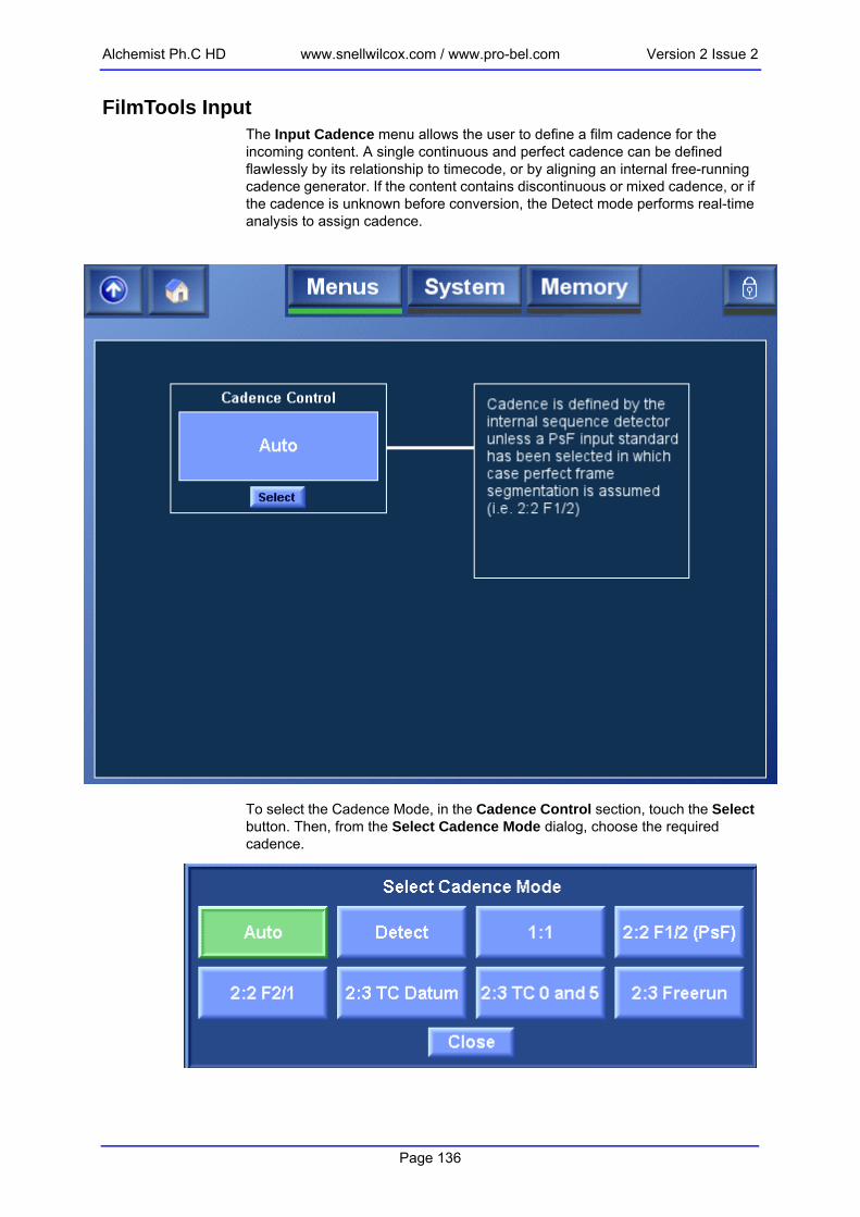
Alchemist Ph.C HD www.snellwilcox.com / www.pro-bel.com Version 2 Issue 2
FilmTools Input The Input Cadence menu allows the user to define a film cadence for the incoming content. A single continuous and perfect cadence can be defined flawlessly by its relationship to timecode, or by aligning an internal free-running cadence generator. If the content contains discontinuous or mixed cadence, or if the cadence is unknown before conversion, the Detect mode performs real-time analysis to assign cadence.
To select the Cadence Mode, in the Cadence Control section, touch the Select button. Then, from the Select Cadence Mode dialog, choose the required cadence.
Page 136

Version 2 Issue 2 www.snellwilcox.com / www.pro-bel.com Alchemist Ph.C HD
AutoCadence is defined by the internal sequence detector unless a PsF input standard has been selected, in which case perfect frame segmentation is assumed (i.e. 2:2 F1/2)This is the default selection.
DetectCadence is defined by the internal sequence detector (even when PsF inputs are selected).
1:1Incoming content is interpreted as 1:1 cadence (field by field or frame by frame motion).
2:2 F1/2 (PsF)All incoming content is interpreted as 2:2 F1/2 (PsF) cadence.
2:2 F2/1All incoming content is interpreted as 2:2 F2/1 cadence.
2:3 TC DatumIncoming content is interpreted as continuous 2:3 cadence derived from continuous input timecode by identifying the specific 2:3 frame type and timecode of an input 'Datum' frame.
2:3 Datum CadenceThis control defines the 2:3 cadence of the Datum frame when the input cadence control is 2:3 TC Datum mode. For more information, see “Understanding 2:3 Datum Cadence” on page 156.
Page 137

Alchemist Ph.C HD www.snellwilcox.com / www.pro-bel.com Version 2 Issue 2
2:3 Cadence Reset
2:3 Datum Timecode
Max Time Pre-Datum
On Valid TC (Default)
Input 2:3 cadence will be defined according to the 2:3 Datum Cadence and Timecode controls when stable input timecode has been detected. The input timecode may be greater or less than specified 2:3 Datum Timecode.
At Datum Input 2:3 cadence will be defined according to the 2:3 Datum Cadence and Timecode controls. The cadence reset occurs when the input timecode is equal to the 2:3 Datum Timecode.
Input Timecode Trigger (Default)
(Default) The 2:3 Datum Timecode is automatically set to match the timecode “Input Trigger” value.
Independent Cadence Trigger
The 2:3 Datum Timecode can be set to any required frame.
0 – 23 hours(Default12 hours)
Defines the start of the Cadence Window. Only applicable when 2:3 Cadence Reset is set to “On Valid TC”. For more information, “Understanding Datum TC Conversion” on page 154.
Page 138

Version 2 Issue 2 www.snellwilcox.com / www.pro-bel.com Alchemist Ph.C HD
2:3 TC 0 and 5Incoming content is interpreted as continuous 2:3 cadence defined by a specific relationship to the frame count of non-drop frame input timecode.
0 and 5 CadenceThis control defines the phase of the relationship between frame count and input timecode. When frame count values of 0 and 5 are present, the 2:3 cadence is interpreted as the selected frame type.
Page 139

Alchemist Ph.C HD www.snellwilcox.com / www.pro-bel.com Version 2 Issue 2
2:3 FreerunIncoming content is interpreted as continuous 2:3 cadence derived from an internal free-running 2:3 cadence generator.
Cadence OffsetThis control enables the cadence of the free-running 2:3 cadence generator to be offset.
Page 140

Version 2 Issue 2 www.snellwilcox.com / www.pro-bel.com Alchemist Ph.C HD
FilmTools Output The FilmTools Output Cadence Control menu enables the user to control the cadence of the converted content. This menu allows the user to select the required cadence including any required relationship with the output timecode.
OffNo specific cadence will be forced. Outgoing content will follow the Input (field by field or frame by frame motion).
2:2 F1/2 (PsF)Outgoing content is generated with 2:2 F1/2 (PsF) cadence.
2:2 F2/1Outgoing content is generated with 2:2 F2/1 cadence.
Page 141

Alchemist Ph.C HD www.snellwilcox.com / www.pro-bel.com Version 2 Issue 2
2:3 TC DatumOutgoing content is generated with continuous 2:3 cadence derived from continuous output timecode by identifying the specific 2:3 frame type and timecode of an output ‘Datum’ frame.
2:3 Datum CadenceThis control defines the 2:3 cadence of the Datum frame when the input cadence control is 2:3 TC Datum mode.2:3 Cadence Reset
On Valid TC(Default)
Output 2:3 cadence will be defined according to the 2:3 Datum Cadence and Timecode controls when stable output timecode has been detected. The output timecode may be greater or less than specified 2:3 Datum Timecode.
At Datum Output 2:3 cadence will be defined according to the 2:3 Datum Cadence and Timecode controls. The cadence reset occurs when output timecode is equal to the 2:3 Datum Timecode
Page 142

Version 2 Issue 2 www.snellwilcox.com / www.pro-bel.com Alchemist Ph.C HD
2:3 Datum Timecode
Max time pre-datumThis control defines the start of the Cadence Window. It is only applicable when 2:3 Cadence Reset is set to “on valid TC”. The default value is 12 hours.
2:3 TC 0 and 5Outgoing content is generated with continuous 2:3 cadence defined by a specific relationship to the frame count of non-drop frame output timecode.
0 and 5 CadenceThis control defines the phase of the relationship between frame count and output timecode. When frame count values of 0 and 5 are present, the 2:3 cadence is interpreted as the selected frame type.
Output Load A Timecode (Default)
The 2:3 Datum Timecode is automatically set to match the “Output A Load” timecode.
Independent Cadence Trigger
The 2:3 Datum Timecode can be set to any required frame.
Page 143

Alchemist Ph.C HD www.snellwilcox.com / www.pro-bel.com Version 2 Issue 2
2:3 FreerunOutgoing content is generated with continuous 2:3 cadence derived from an internal free-running 2:3 cadence generator.
Cadence OffsetThis control enables the cadence of the free-running 2:3 cadence generator to be offset.For more information, see “Understanding 2:3 Datum Cadence” on page 156.
Page 144

Version 2 Issue 2 www.snellwilcox.com / www.pro-bel.com Alchemist Ph.C HD
FilmTools Control The FilmTools Control menu enables the FilmTools Mode and Film Aperture settings to be specified.
Mode
Film Aperture
Auto(Default)
Selects between synchronized or interpolated conversion as appropriate depending on the input and output formats specified. See “Conversion Tables” on page 151. Interpolation gives the smoothest motion profile. Synchronize disables temporal interpolation and maintains clean frames. Note synchronize mode can cause field/frame drops or repeats depending on the input and output frequencies selected.
Synchronize Forces the conversion by synchronization.
Interpolation Forces the conversion by interpolation.
Normal(Default)
This aperture maximizes the vertical resolution from the incoming film material. This is the optimum aperture for most applications.
Sharp This aperture maintains maximum possible vertical resolution with the result that it is less tolerant to film sequence detection errors
Safe This aperture is film safe. It is the most tolerant to film sequence detection errors. Note this mode is useful in applications where the film content contains mixed cadence regions.
Page 145
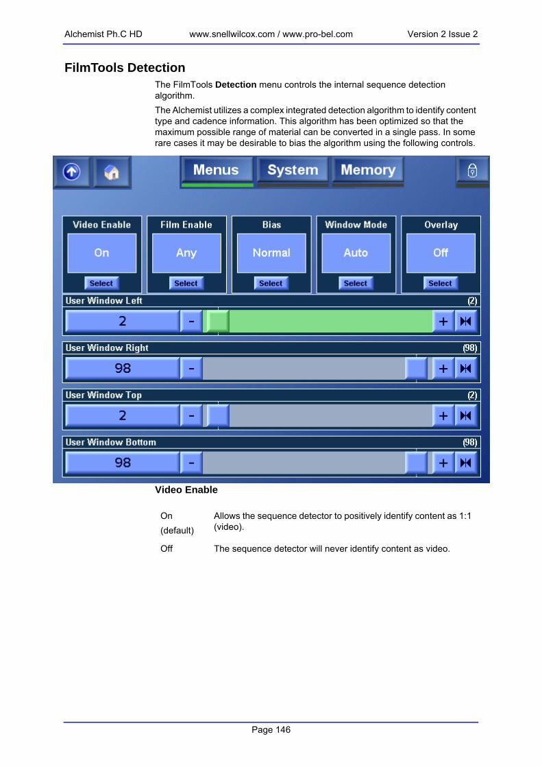
Alchemist Ph.C HD www.snellwilcox.com / www.pro-bel.com Version 2 Issue 2
FilmTools Detection The FilmTools Detection menu controls the internal sequence detection algorithm.The Alchemist utilizes a complex integrated detection algorithm to identify content type and cadence information. This algorithm has been optimized so that the maximum possible range of material can be converted in a single pass. In some rare cases it may be desirable to bias the algorithm using the following controls.
Video Enable
On(default)
Allows the sequence detector to positively identify content as 1:1 (video).
Off The sequence detector will never identify content as video.
Page 146

Version 2 Issue 2 www.snellwilcox.com / www.pro-bel.com Alchemist Ph.C HD
Film Enable
Bias
Window ControlThis control allows the sequence and cut detection to be restricted to specific areas of the image. A typical detection application would be to avoid sequence detection errors caused by artifacts near the images edges. A typical cut detection application would be to prevent the detection of cuts occurring within a specific region of the image.
Any (Default) Allows the sequence detector to identify film of any cadence. This maybe 2:2, 2:3, discontinuous 2:3, orphan fields, varispeed or animation.
2:2 Forces the sequence detection to identify film content as 2:2 cadence only. Content maybe F1/2 or F2/1.
2:3 Forces the sequence detection to identify film content as 2:3 cadence only. The 2:3 cadence may be discontinuous.
Animation Optimized sequence detection algorithm specifically for animation.
Off The sequence detector will not identify content as film.
Normal(Default)
This is the optimum setting for most applications. The detection algorithms have been optimized to give the most accurate results for the greatest possible range of material.
Video 2,Video 1,Film 1,Film 2
In some rare cases in may be desirable to bias the sequence detector such that it is more likely to detect video or more likely to detect film. Video 2 biases more strongly towards video than Video 1. Similarly Film 2 biases more strongly towards film than Film 1.
Auto(Default)
The sequence/cut detection region will be set to default values.
Track Input Blanking
The sequence/cut detection region will track with the settings for input blanking.
User The user may manually define a specific sequence/cut detection region.
Page 147

Alchemist Ph.C HD www.snellwilcox.com / www.pro-bel.com Version 2 Issue 2
Window OverlayThe overlay permits adjustment of the active sequence/cut detection region.
User Window
Off(Darken)
The sequence/cut detection region overlay is disabled.
Darken The active sequence/cut detection region is shown with reduced luminance.
Greyed The active sequence/cut detection region is shown in mono
Left0%-100%(Default 1%)
Defines the left edge of the detection region as a percentage of the picture width.
Right0%-100%(Default 99%)
Defines the right edge of the detection region as a percentage of the picture width.
Top0%-100%(Default 1%)
Defines the top edge of the detection region as a percentage of the picture height.
Bottom0%-100%(Default 99%)
Defines the bottom edge of the detection region as a percentage of the picture height.
Page 148

Version 2 Issue 2 www.snellwilcox.com / www.pro-bel.com Alchemist Ph.C HD
Operational ExamplesThis section provides examples of common FilmTools conversions.
Operational Example 1This example describes how to perform a FilmTools conversion from 625 23.98PsF to 525 59.94i 2:3 (2:3 Insertion). 1. In the Conversion menu, turn FilmTools On.
2. In the Input menu, select 625 23PsF Input standard.
3. In the Output menu, select 525 59i Output standard.
4. In the FilmTools Input menu, set the Input Cadence control to Auto.
5. In the FilmTools Output menu, set the Output Cadence control to 2:3 Freerun.
Operational Example 2This example describes how to perform a FilmTools conversion from 1080 59.94i 2:3 (with video inserts) to 1080 23.98 PsF. Video inserts will be converted to film.1. In the Conversion menu, turn FilmTools On.
2. In the Input menu, select 1080 59i Input standard.
3. In the Output menu, select 1080 23PsF Output standard.
4. In the FilmTools Input menu, set the FilmTools Input Cadence control to Auto.
5. In the FilmTools Detection menu, set Film Enable to On.
6. In the FilmTools Output menu, set output Cadence to 2:2 F1/2 (PsF).
Operational Example 3This example describes how to perform a FilmTools conversion from 1080 59.94i 2:3 (with video inserts) to 1080 47i . The film elements will be processed as in example 2, and the video elements will remain as video.1. In the Conversion menu, turn FilmTools On.
2. In the Input menu, select 1080 59i Input standard.
3. In the Output menu, select 1080 47i Output standard.
4. In the FilmTools Input menu, set the FilmTools Input Cadence control to Auto.
5. In the FilmTools Detection menu, set Film Enable to On.
6. In the FilmTools Output menu, set output Cadence to Off.
Before performing any FilmTools conversion, it is recommended that the Alchemist is referenced to the input or an external reference source.See “Genlock & FilmTools” on page 156.
Note:
Page 149

Alchemist Ph.C HD www.snellwilcox.com / www.pro-bel.com Version 2 Issue 2
Operational Example 4This example describes how to perform a FilmTools conversion from 1080 23.98PsF to 525 59.94i 2:3 — the source is a feature film with continuous cadence and timecode split across two tapes. Tape 1 10:00:00:00 > 10:59:59:29Tape 2 11:00:00:00 > 11:30:00:00Output cadence should start at hour 10:00:00:00 with a start phase of AA. Setup:1. In the Conversion menu, turn FilmTools On.
2. In the Input menu, select 1080 23PsF Input standard.
3. In the Output menu, select 525 59i Output standard.
4. In the FilmTools Input menu, set the Input Cadence control to 2:2 F1/2.
5. In the FilmTools Output menu, set output cadence control to 2:3 TC Datum.
6. Set Output 2:3 Datum Cadence to AA.
7. Set 2:3 Cadence Reset to At Datum
8. Set an independent cadence datum cadence of 10:00:00:00
Both tapes can be converted without any further setup.See “Understanding 2:3 Datum Cadence” on page 156.
Operational Example 5This example describes how to perform a FilmTools conversion from 1080 25PsF to 1080 24PsF. The PsF material contains some moderate motion speeds and it is desirable to maintain a smooth motion profile in the output. This conversion is desirable in applications where it is deemed unacceptable to perform a 4% speed adjustment during playout. Typical examples would include applications where the audio is critical (e.g. Operas) or when it is crucial to maintain the exact program length (e.g. adverts). Setup:1. In the Conversion menu, turn FilmTools On.
2. In the Input menu, select 1080 25PsF Input standard.
3. In the Output menu, select 1080 24PsF Output standard.
4. In the FilmTools Input menu, set the Input Cadence control to Auto.
5. In the FilmTools Output menu, set the Output Cadence control to 2:2 F1/F2 (PsF).
6. In the FilmTools Detection menu, set the film mode to Auto.
Page 150

Version 2 Issue 2 www.snellwilcox.com / www.pro-bel.com Alchemist Ph.C HD
FIN
Conversion TablesThe FilmTools suite comprises a number of different temporal conversion techniques. Each technique has been optimized for a specific application. The Alchemist Ph.C – HD will select the most appropriate technique depending on the input/output standard combination selected. These tables indicate which conversion technique the alchemist will adopt depending on the various standard combinations.
KEY
S Synchronisation
SR Synchronisation with 2:3 repair
IS Interpolation or Synchronisation
M Motion Compensated Interpolation
P Pulldown (2:3) Insertion
PM Pulldown (2:3) Insertion via Motion Compensated Interpolation
D DEFT/DEFTplus (2:3 pulldown removal)
FILM OUTPUT
Native 23 23 24 24 25 29 30
Transport 47 2:2 59 2:3 48 2:2 60 2:3 50 2:2 59 2:2 60 2:2
ILM PUT
23 47 2:2 S P IS IS IS IS IS
23 59 2:3 D SR IS IS IS IS IS
24 48 2:2 IS IS S P IS IS IS
24 60 2:3 IS IS D SR IS IS IS
25 50 2:2 IS IS IS IS S IS IS
29 59 2:2 IS IS IS IS IS S IS
30 60 2:2 IS IS IS IS IS IS S
Page 151

Alchemist Ph.C HD www.snellwilcox.com / www.pro-bel.com Version 2 Issue 2
VIDEO OUTPUT
Native 47 48 50 59 60
Transport
FILM INPUT
23 47 2:2 S IS IS IS IS
23 59 2:3 D IS IS S IS
24 48 2:2 IS S IS IS IS
24 60 2:3 IS D IS IS S
25 50 2:2 IS IS S IS IS
29 59 2:2 IS IS IS S IS
30 60 2:2 IS IS IS IS S
All film to video conversions maintain the input temporal sampling frequency
VIDEO OUTPUT
Native 47 48 50 59 60
VIDEO INPUT
47 S M M M M
48 M S M M M
50 M M S M M
59 M M M S M
60 M M M M S
Note:
Page 152

Version 2 Issue 2 www.snellwilcox.com / www.pro-bel.com Alchemist Ph.C HD
FILM OUTPUT
Native 23 23 24 24 25 29 30
47 2:2 59 2:3 48 2:2 60 2:3 50 2:2 59 2:2 60 2:2
VIDEO INPUT
47 S P M P M M M
48 M P S P M M M
50 M PM M PM S M M
59 M PM M PM M S M
60 M PM M PM M M S
Page 153

Alchemist Ph.C HD www.snellwilcox.com / www.pro-bel.com Version 2 Issue 2
Understanding Datum TC Conversion
2:3 TC Datum with ‘On Valid TC’ FilmTools allows both input and output 2:3 cadence phase to be locked to timecode. 2:3 TC Datum mode allows the user to configure a datum timecode with a specified 2:3 phase. When On Valid TC is selected, upon receipt of valid timecode the Alchemist will perform the required Datum calculations ensuring the cadence will be locked to the specified Datum timecode. The cadence window defines a 24 hour period of time used to define the behavior of the Datum calculations. If the timecode was post Datum the Alchemist will extrapolate forwards in time. If the timecode was pre-datum the Alchemist will extrapolate backwards in time. The Max Time Pre-datum defines at what timecode the Datum calculations switch from extrapolating forwards to extrapolating backwards. If incorrectly configured the user may not get the desired cadence. For most cases the default value of 12 hours for Max Time Pre-datum will give the desired cadence.
Example: (Figure 1)As shown in Figure 1 the Max Time Pre-datum is set to 9 hours. This gives a start of cadence window of 01:00:00:00 and a corresponding end of cadence window of 00:59:59:29 (24 hours later). The Datum timecode is set to 10:00:00:00. For any timecode after the 01:00:00:00 but before 10:00:00:00 the cadence will be extrapolated backwards. For any timecode after 10:00:00:00 but before 01:00:00:00 the cadence will be extrapolated forwards. If the Max Time Pre-datum had been set to 1 hour, it would mean any timecode before 09:00:00:00 would be extrapolated forwards. Had the user wanted to lock input cadence to the datum of 10:00:00:00 but started the tape rolling at 08:00:00:00 they would have wanted the calculation to be extrapolated backwards. With the current settings the resultant cadence wouldn’t have been phase locked and continuous up to the datum.
2:3 TC Datum with ‘At Datum’ If the user simply wanted to lock input or output 2:3 cadence phase to timecode without the Alchemist performing the Datum calculations upon detection of valid timecode the 2:3 Cadence Reset should be set to At Datum. In this mode the Alchemist will reset the cadence to the specified phase when timecode is equal to the specified 2:3 Datum Timecode.
Page 154

Version 2 Issue 2 www.snellwilcox.com / www.pro-bel.com Alchemist Ph.C HD
Afte
r the
cad
ence
has
bee
n se
t relat
ive
to th
e Dat
um o
n re
ceip
t of v
alid ti
mec
oe, it w
ill
cont
inue
inde
finat
ely
until tim
ecod
e is d
isru
pted
. Thi
s m
ay e
xcee
d a
24 h
our p
eriod.
Figu
Datu
m T
imec
ode
10:0
0:00
:00
2:3
Datu
m C
aden
ce =
AA
Valid
TC p
rese
nt a
t 11:
00:0
0:00
Num
ber o
f fra
mes
since
dat
um tim
ecod
e =
107,
892
(df)
107,
892
mod
5 =
2
Ther
efor
e:
Cad
ence
= A
A +
2
Cad
ence
extra
pola
ted
forw
ards
to 1
1:00
:00:
00 =
BC
Not
to s
cale
TIM
E
Star
t of C
aden
ce W
indo
w
01:0
0:00
:00
End
of C
aden
ce W
indo
w
00:5
9:59
:29
Cad
ence
ext
rapo
late
d bac
kwar
dsCa
denc
e ex
trap
olat
ed fo
rwar
ds
24 h
our c
aden
ce w
indo
w
Con
tinuo
us cad
ence
Valid
TC p
rese
nt a
t 09:
00:0
0:00
Num
ber o
f fra
mes
since
dat
um tim
ecod
e =
107,
892
(df)
107,
892 m
od 5
= 2
Ther
efor
e:
Cad
ence
= A
A -2
Cad
ence
extra
polate
d ba
ckwar
ds to
09:
00:0
0:00
= C
D
A AAf1 0
Af2
B BBf1 +1
Bf2
B BCf1 +2
Cf2
C CDf1 +3
Df2
D DDf1 +4
Df2
Df2
D DDf1 -1
Df2
C CDf1 -2
Af2
AA
-2AA
AA
+ 2
Max
Tim
e Pr
e Dat
um
9 ho
urs
Valid
tim
ecod
e ha
s a
value
betw
een
datu
m tim
ecod
e
and
star
t of c
aden
ce w
indo
w (2
:3 D
atum
Tim
ecod
e –
Max
Tim
e Pr
e Dat
um)
Valid
tim
ecod
e ha
s a
valu
e be
twee
n da
tum
tim
ecod
e
and
end
of cad
ence
windo
w.
30 fr
ames
/ s dr
op fr
ame
timec
ode
assu
med
Cade
nce
Con
trol =
2:3
TC D
atum
2:3 Dat
um T
imec
ode
= 10
:00:00
:00
Max
Tim
e Pre
Dat
um =
9 hou
rs
2:3 Dat
um C
aden
ce =
AA
2:3 Cad
ence
Res
et =
At D
atum
Con
trol
Set
tings
:
Ext
rapo
late
d ca
denc
e
Exam
ple
1:Ex
ample
2:
re 1
Page 155

Alchemist Ph.C HD www.snellwilcox.com / www.pro-bel.com Version 2 Issue 2
Figu
Understanding 2:3 Datum CadenceUnderstanding the 5 frame types of a 2:3 sequence AA, BB, BC, CD, DD
The 5 frame types describe each of the 5 phase within a 10 field 2:3 sequence. 4 sequential source film frames are shown in bold in figure 2 - A, B, C, D. Each phase is identified by describing the first and second field of the video frame using the A, B, C, D reference.For examplePhase 2 is described as “BB”. In this instance both the first and second fields are derived from source frame B.Phase 4 however is derived from source frames C and D. In this case the label would read “CD”.
Genlock & FilmToolsIt is recommended practice to reference the Alchemist when performing any FilmTools conversion. It is important to reference the Alchemist as this prevents the frame synchronizer from performing additional frame drops or repeats. These extra drops or repeats may introduce an irregular motion profile or in some cases cause a discontinuous cadence.This can be achieved by:• Setting the reference menu item to Input. • Setting the reference menu item to External and applying an external refer-
ence. The source should share the same externally applied reference.
A
AA
f1
A
f2
B
BB
f1
B
f2
B
BC
f1
C
f2
C
CD
f1
D
f2
D
DD
f1
D
f2
D
f2
D
f1
D
f2
C
f1
B
f2
Start of 10 field sequence AA (A frame)
B
f1
A
f2
A
f1
End of 10 field sequence
AA = 2 field frameBBB = 3 field frame
CC = 2 field frameDDD = 3 field frame
re 2
Page 156

Version 2 Issue 2 www.snellwilcox.com / www.pro-bel.com Alchemist Ph.C HD
Questions & AnswersQ1. Why would I want to set up a sequence detection region?A1. Pictures edges may contain artifacts unrelated to the image content which if not excluded from the sequence detection could impede or prevent correct sequence detection. Alternatively, some complex material may contain images with different cadences present. This feature allows the user to lock onto the favored cadence. Q2. Why would I want to use “On Valid Timecode” mode of operation?A2. The feature is very useful in applications where content has been spanned across multiple tapes. Each tape must contain constant cadence and timecode following on from the previous tape. Q3. Can I leave the Alchemist in Detect mode all the time?A3. Yes you can. However, in some rare circumstances material may not contain a clear motion signature. Q4. Why does the latency of the Alchemist increase when FilmTools is enabled?A4. In order to perform high quality sequence detection and process sequence changes correctly from the first field of the new sequence the Alchemist requires a longer period of analysis. Q5. Can the user set up independent cadences on output A and output B?A5. This is not possible – the output cadence defined applies to both Output A and B.Q6. What happens if I have some 720P 50/59/60 material with a 2:2 cadence and I set the input cadence alignment to 2:2 F1/2 (PsF)?A6. The Alchemist will use the field marker present in the timecode due to the absence of an F sync in these standards. If there is no input timecode the 2:2 sequence will free run.Q7. Why do I need the video blur control? A7. Video blur is used to create a more naturalistic film originated look on video to film conversions.Q8. Can I use embedded audio when I select a SlowPAL output format (625 23.98PsF and 625 24PsF)? A8. Yes the embedded audio will be present but it will be 48KHz. In addition all AES outputs will also be 48KHz.Q9. Can I use embedded audio when I select a SlowPAL input format (625 23.98PsF and 625 24PsF)? A9. Yes the system will accept embedded audio from a SlowPAL source however it must be 48KHz. If Slow audio in is required we recommend the use of AES. Q10. When might I need to bias the sequence detector? A10. The Bias control is useful when converting material that does not contain a clear motion signature. This can occur for many reasons, such as:• Severely intercut film, varispeed or video• Film containing overlaid or transparent video effects/graphics• Excessively enhanced or compressed clips• Film originated source with field (video) based noiseQ11. Is it possible to force F1 or F2 cuts whilst simultaneously forcing an output cadence? A11. No, forced cuts and forced output cadence are mutually exclusive. A forced 2:3 output for example would by definition contain sequence changes on both a F1 and a F2. With FilmTools enabled the output cadence must be set to OFF if forced cuts are required.
Page 157

Alchemist Ph.C HD www.snellwilcox.com / www.pro-bel.com Version 2 Issue 2
FilmTools Glossary
2:2 F1/F2 A film frame being transported as 2:2 (PsF) is placed into two consecutive video fields. F1/F2 denotes that the film frame is carried in a field one and the following field two. This is commonly referred to “normal dominance” or “perfect cadence”. See PsF.
2:2 F2/F1 A film frame being transported as 2:2 (PsF) is placed into two consecutive video fields. F2/F1 denotes that the film frame is carried in a field two and the following field one. This is commonly referred to “reverse dominance” or “reverse cadence”. See PsF.
2:3 Datum Timecode
Term used to assist in defining a FilmTools conversion on the Alchemist Ph.C - HD. The 2:3 Datum Timecode identifies a specific frame for which the user can specify an associated phase of 2:3 cadence (see 2:3 Datum Cadence).
2:3 Pulldown A telecine uses a technique called 2:3 pulldown (sometimes also called 3:2 pulldown) to convert Film from 23.98Hz to 59.94Hz videotape. For every 4 frames of film there are 5 frames of 59.94 video. The telecine alternately places 1 film frame across 2 fields, the next across 3, the next across 2 and so on.
Aliasing An artifact associated with sampled signals. This undesirable effect is caused by sampling frequencies being too low to faithfully reproduce the frequencies present in the original signal.
Animation Any content with a frame rate of 12Hz or below where the cadence may have no regular pattern.
Aperture The characteristic frequency response of a filter which describes the effects on a signal being processed by that filter.
Cadence The pattern of video fields that create a net frame rate lower than the video frame rate that carries them.
Cadence Window
The cadence window defines a 24 hour period of time used to define the behavior of the 2:3 Timecode Datum calculations. The window definition and input timecode will define whether the 2:3 Datum Cadence is extrapolated backwards or forwards from the 2:3 Datum Timecode. This concept is only applicable to the 2:3 Datum Cadence feature.
Clean frames Output fields or frames are derived directly from a single input frame with no interpolation.
Content Type Content can fall into a variety of types based on its properties. In the FilmTools context type categories include 2:2, 2:3, varispeed, animation and video.
Page 158

Version 2 Issue 2 www.snellwilcox.com / www.pro-bel.com Alchemist Ph.C HD
DEFT Historically DEFT represents a motion artifact free conversion from NTSC film originated video material to PAL. The post production trend is to shoot material on film (24Hz) and then perform a telecine transfer to videotape (59.94/2:3). A DEFT conversion process takes this 2:3 material, detects the sequence and eliminates the redundant field in a 3 field frame, and can therefore produce PAL images at a frame rate of 23.98Hz. This video is recorded on a specially modified PAL VTR. The 23.98 to 25Hz frame shift is achieved by replaying the material back on a standard VTR. In more recent times this process has been applied to the HD domain as well i.e. 1080 59.94i 2:3 to 1080 23.98PsF.
DEFTplus The content targeted at the DEFT conversions evolved over time. Material soon contained both film and video elements cut together throughout a program. This content required a 2 pass conversion. One through a DEFT, and the other through an Alchemist. The results would then be edited together to provide the optimum conversion. DEFTplus offers optimal handling of the video content as well as the film originated content by switching seamlessly from a DEFT conversion to a video conversion on a shot by shot basis. Source video movement at 59.94Hz can be converted to movement at 47.95HZ using Ph.C Motion Compensation. Alternatively the video elements can by converted to 24Hz (Video to film) to maintain a consistent frame based appearance
Discontinuous 2:3 Sequence
It is common for the editing process to be performed post telecine. When editing is performed to 2:3 there is a potential for disruptions in the 2:3 sequence. These can be 3 field sequences adjacent to other 3 field sequences, and 2 field sequences adjacent to other 2 field sequences. Also there are cases where we have single fields present that are not part of any sequence (Orphan fields). These disruptions caused by editing create a “broken 2:3 sequence”.
Field Dominance
Defines whether a field 1 or field 2 represents the first field of a progressive frame. See also 2:2 F1/F2 & 2:2 F2/F1
Film Any content with a net frame rate of 30Hz or below.
Input Trigger Term used when defining a timecode conversion. The input trigger is the value of the input timecode that defines when an output timecode event occurs.
Interpolation The process of deriving new samples from a two or more source samples.
Interpolation (Spatial)
The process of deriving new samples from a two or more source samples associated with the same point in time but different points in space. In the context of video, by using different lines and pixels from the same field or frame.
Interpolation (Temporal)
The process of deriving new samples from a two or more source samples associated with the same point in space but different points in time. In the context of video, by using pixels from the subsequent fields or frames.
Page 159

Alchemist Ph.C HD www.snellwilcox.com / www.pro-bel.com Version 2 Issue 2
Mixed Cadence Content that contains two or more different cadences occurring concurrently in different regions of the image. Typical examples include film content with overlaid interlaced captions or film content derived from two different sources (with different cadences).
Mixed Content Generic term used to define content which could contain mixed cadence or content that changes type or cadence over time. See Content Type
Mixed Media See Mixed Content.
Orphan Field See Discontinuous 2:3 Sequence.
P-Film This process offers all the advantages of DEFTplus for 50Hz mixed media sources.
PsF A Progressive Segmented Frame (PsF) format splits a progressive image into two sequential fields. It is identical to 2:2 in terms of motion profile.
Sequence Detection
This is the act of finding film frame boundaries. For “perfect” PsF or 2:3 sequences, this will produce a regular pattern of frames. For “non-perfect” sequences the pattern will not be regular and might have discontinuities at edit points for example.
Synchronize Temporal conversion without the use of interpolation. If input and output field or frame rates are not identical then field or frame drops or repeats must occur.
Varispeed Refers to film originated material which has been played off speed. For example, speed up could be performed by dropping the third field in a three field frame.
Video Any content with motion portrayal at a frequency greater than 30 Hz.
Video-to-Film Video-to-Film processing is the conversion of video (interlaced / field based formats) to frame based formats (e.g. 2:2 / PsF.
Video Blur Technique used during the Video-to-Film process to modify temporal processing to create a more naturalistic film originated look.
Page 160

Version 2 Issue 2 www.snellwilcox.com / www.pro-bel.com Alchemist Ph.C HD
Appendix E: Dolby EOverview
The Dolby E option enables the Alchemist Ph.C – HD to seamlessly handle Dolby E with ease while performing any type of up, down, cross and standards conversion. It provides an integrated transcoding and decoding solution for up to two streams of Dolby E audio.Multi channel audio has been with us for many years and with the advent of HD Direct to Home (DTH) services it is increasingly used for major live sporting events and concerts, as well as drama, documentary and features. Dolby E provides content owners and distributors with a solution to manage these multiple channels. However, as Dolby E must be correctly referenced and aligned to the video, this poses a problem when standards converting, as the Dolby E must be transcoded to the new video reference and correctly aligned with the new frame rate. The Dolby E option for the Alchemist Ph.C – HD provides a complete integrated solution to solve this problem for broadcasters and post production. Key Features:• Eliminates the need for external boxes and infrastructure • Dolby E processing available in all conversion modes
- Frame rate standards conversion as well as up, down and cross conversion modes- Transcode- Decode
• Dolby E guard band alignment• Fully integrated latency compensation
- Automatic audio and video alignment- Lip-sync maintained
• Range of features to accommodate all potential user applications• Unique Map modes to route decoded Dolby E to AES and embedded outputs• Powerful, easy to use, control interface• Dolby D - Decode
Page 161

Alchemist Ph.C HD www.snellwilcox.com / www.pro-bel.com Version 2 Issue 2
Dolby® E Control InterfaceThis section describes the control interface of the Alchemist Ph.C – HD’s Dolby E functions. Dolby E processing is inextricably linked to general audio processing and as such, the Alchemist’s general audio setup functions are also described in this section.Users of previous versions of the Alchemist will notice that the audio setup menus have been changed somewhat to simplify audio configuration.
Audio Display Tab (Home Screen)The Audio display tab on the Home screen illustrates Audio Input / Audio Output status. Dolby Sources and types, and the Dolby program configuration.
EMB In The EMB In indicators display the EMB input status.• Green indicates that a valid embedded input signal is
present.• Red indicates that no embedded input signal is pres-
ent.
AES In The AES In indicators display the AES input status.• Green indicates that a valid AES input signal is pres-
ent.• Red indicates that no AES input signal is present.
Page 162

Version 2 Issue 2 www.snellwilcox.com / www.pro-bel.com Alchemist Ph.C HD
Out Src These indicators display the audio output pair status.• The text for each describes the selected source cur-
rently routed to each output.• Green indicates that the selected source is valid.• Red indicates that the selected source is not valid.
Dolby 1 / Dolby 2 Source
This indicates the input source that is routed to the respective Dolby channel decoder.• Green indicates a valid Dolby E or Dolby D signal• Yellow indicates a valid PCM signal• Red indicates that no Dolby E, Dolby D or PCM signal
is present.
Dolby 1 / Dolby 2 Source Type
This indicates the bitstream format that is being routed to the respective Dolby channel decoder.• Green indicates a valid Dolby E or Dolby D signal.• Red indicates that there is no valid Dolby E or Dolby D
signal.• Yellow indicates a valid PCM signal.
Dolby 1 / Dolby 2 Configuration
This displays the Dolby program configuration being routed to the respective Dolby channel decoder.
Page 163

Alchemist Ph.C HD www.snellwilcox.com / www.pro-bel.com Version 2 Issue 2
Audio Control The Audio Control page is accessed by touching anywhere on the audio tab.
Audio Delay Offset
This allows the overall audio delay of the unit to be set. This value will be displayed on the Audio Channel Control screens.
Any audio delay added to individual PCM or Dolby channels is added to this delay.
Control Touch the Control button to access the audio control pages from which the Alchemist’s audio setup can be configured.
Dolby E Touch Dolby E to access the Dolby E setup page.
Note:
Page 164

Version 2 Issue 2 www.snellwilcox.com / www.pro-bel.com Alchemist Ph.C HD
Audio Control (Audio Pair 1 to Audio Pair 8) This page allows the user to configure each of the audio outputs.
For each of the Alchemist Ph.C – HD’s eight audio pairs the following information is shown.
Source This displays the source that has been configured for each of the output audio pairs. If the source is present and valid, it is displayed in green. If the source is absent, or invalid. it is displayed in red.
Type In the absence of Dolby E output, this displays whether the output is AES audio or data.
Gain If the Gain indicator is yellow, the gain on the channel has been changed from the default setting. This indicator applies only to PCM.
Page 165

Alchemist Ph.C HD www.snellwilcox.com / www.pro-bel.com Version 2 Issue 2
Touch Source/Type to specify the input source and type.Touch Gain/Delay/Tone to adjust the channel gain and delay options.
Audio Pair 1 to Audio Pair 8 (PCM/Data Controls)The settings on the Audio Control pages enable the channel gain, delay, Tone, Mute and Mono options to be adjusted.These settings are only applicable to PCM audio / Data only. Dolby E tone and gain options are configured from the Dolby E pages.
Delay If the Delay indicator is yellow, the Delay on the channel has been changed from the default setting. This indicator applies only to PCM / Data signals.Note that this differs from the global audio delay offset, applied to all channels, that is adjusted on the Audio Control page.
Tone If the Tone indicator is yellow, the output channel is currently producing a tone. This indicator applies only to PCM / Data signals.
Gain This allows the gain of the left and right channels of the pair to be adjusted. The range of control is ±12 dB.Touch Reset to return the gain control to its preset value of 0 dB.
Page 166

Version 2 Issue 2 www.snellwilcox.com / www.pro-bel.com Alchemist Ph.C HD
Mono Touch the Mono button to take an average of the left and right channels and apply that average to both.
Mute When selected, both channels will be muted.
Tone Touch tone to generate the tone specified in the Tone Type section.
Tone Type The audio pair may be assigned a fixed frequency tone. To change the tone type, touch Select and in the dialog that appears, select the tone type.
Pair Audio Delay(PCM/Data Audio Only)
The audio delay for each pair can be adjusted individually. This delay is added to the global audio delay and the unit’s internal processing delay. The total delay for the pair is displayed in the Total field. The values of this delay vary according to the conversion being made and are listed in the “Latency Tables” appendix of the Alchemist Ph.C – HD Operator’s manual.To change the delay offset for the audio pair, use the slider bar.Note: the system latency is dependent on the following user controls - input standard, output standard, FilmTools, Min Delay and Synchro Timecode conversion.In Timecode synchro mode, the system delay can change by a maximum of one output standard frame. The modified system delay is displayed on the Home page.
Page 167

Alchemist Ph.C HD www.snellwilcox.com / www.pro-bel.com Version 2 Issue 2
Audio Pair 1 Source to Audio Pair 8 SourceThe settings on these pages enable the input source for any of the eight audio output pairs to be specified.
Inputs that have a valid source present are displayed in green. Inputs that do not a have a valid source present are displayed in red. When selected as the input for the selected audio pair, the source is illuminated.To select the audio type, touch PCM or Data. These options are not available if a Dolby source has been specified.
Page 168

Version 2 Issue 2 www.snellwilcox.com / www.pro-bel.com Alchemist Ph.C HD
Dolby EThe Dolby E menu enables the Dolby E channels to be configured. Each channel consists of a dedicated Dolby E encoder and decoder module. The Dolby E page is divided in two. The top half of the page contains the controls for Dolby channel 1 and the bottom half of the page contains the controls for Dolby channel 2.
Source This displays the input on which the Dolby E input stream is present. It can be present on either AES pairs 1 to 8, or on Embedded pairs 1 to 8.To specify a different input source, touch Select.
IP Alignment This displays the Dolby E input alignment, which can be:• Advanced by one input frame.• Co-timed with the video signal.• Delayed by one input frame.To change the input alignment, touch Select.The input alignment needs to be selected based upon what devices are upstream from the Alchemist.
Decoder Input This displays the input to the Dolby decoder channel, the Dolby E/D program configuration and associated bit depth.
Page 169

Alchemist Ph.C HD www.snellwilcox.com / www.pro-bel.com Version 2 Issue 2
Monitor The Monitor function enables a predefined method of operation in which decoded audio pairs are automatically assigned to specific AES outputs, thus maintaining program configuration. No change is made to the embedded output mapping, and the mapped AES outputs will not be subjected to any audio gain or delay processing. This control overrides any other mapping to the relevant 4 AES outputs.In this mode:• Dolby E Bitstream 1 will always be decoded to AES
outputs 1 to 4.• Dolby E Bitstream 2 will always be decoded to AES
outputs 5 to 8.Both outputs will adopt the same structure and configuration as the Dolby E.For example, if Dolby E Bitstream 1 and 2 both have a 5.1 + 2 program configuration, the output on the AES BNC outputs would be structured as shown in the diagram below.
1 2 3 4 5 6 7 8
Dolby Bitstream 1 Dolby Bitstream 2
Bitstream 1 Pair 1L/R
Bitstream 1 Pair 2C/LFE
Bitstream 1 Pair 3Ls/Rs
Bitstream 1 Pair 4Lt/Rt
Bitstream 2 Pair 1L/R
Bitstream 2 Pair 2C/LFE
Bitstream 2 Pair 3Ls/Rs
Bitstream 2 Pair 4Lt/Rt
AES OUTPUTS
AES BNC’s
Encoder Output This displays the output from the Dolby encoder channel, the Dolby E program configuration and associated bit depth.Touch this control to access the Encoder options page, on which a tone for the Dolby channel can be configured and applied, a mute can be applied to the channel, and the channel delay offset can be specified. See page 172 for more information.
Page 170

Version 2 Issue 2 www.snellwilcox.com / www.pro-bel.com Alchemist Ph.C HD
Map Decode The Map Decode function enables a predefined mode of operation in which decoded audio pairs will be automatically assigned to specific embedded and AES channels, thus maintaining program configuration.This mapping for the embedded outputs will override any other mapping to these 4 embedded outputs. The AES mappings can be overridden by the Decoder Monitor function.In this mode:• Dolby E Bitstream 1 will always be decoded and
embedded on channels 1 to 4.• Dolby E Bitstream 2 will always be decoded and
embedded on channels 5 to 8.Both outputs will adopt the same structure and configuration as the Dolby E.For example, if Dolby E Bitstream 1 and 2 both have a 5.1 + 2 program configuration, the output embedded within the SDI will be structured as follows.
1 2 3 4 5 6 7 8
Dolby Bitstream 1 Dolby Bitstream 2
Bitstream 1 Pair 1L/R
Bitstream 1 Pair 2C/LFE
Bitstream 1 Pair 3Ls/Rs
Bitstream 1 Pair 4Lt/Rt
Bitstream 2 Pair 1L/R
Bitstream 2 Pair 2C/LFE
Bitstream 2 Pair 3Ls/Rs
Bitstream 2 Pair 4Lt/Rt
Embedded OUTPUTS
Embedded Pairs
OP Alignment This displays the Dolby E output alignment, which can be:• Advanced by one output frame.• Co-timed with the video signal.• Delayed by one output frame.To change the output alignment, touch Select.The output alignment needs to be selected based upon what devices are downstream from the Alchemist.
Page 171

Alchemist Ph.C HD www.snellwilcox.com / www.pro-bel.com Version 2 Issue 2
EncoderThe settings on the Encoder page allow tone, mute and delay offset to be applied to the Dolby encoder output.
Tone Type The Dolby encoder may be assigned a fixed frequency tone. To change the tone type, touch Select and in the dialog that appears, select the tone type.Note: Program configuration and Metadata follow the input to the decoder. Any program configuration which utilizes a .1 / LFE channel will contain a 100Hz test tone when the Tone is activated.
Tone Touch Tone to generate the tone specified in the Tone Type section.
Mute Touch Mute to apply a mute to the Dolby encoder output.
Delay Offset The audio delay for each Dolby encoder channel can be adjusted individually. The total delay for the pair is displayed in the Total field and is the sum of:System Delay + Dolby Input Alignment + Dolby Output Alignment + Master (Global) Delay + Individual Channel Delay (configured here).The values of the system delay vary according to the conversion being made and are listed in the “Latency Tables” appendix of the Alchemist Ph.C – HD Operator’s manual.To change the delay offset for the audio pair, use the slider bar.
Page 172

Version 2 Issue 2 www.snellwilcox.com / www.pro-bel.com Alchemist Ph.C HD
1080/50i5.1 + 2 Emb
80/59.94i + 2 Emb 1
Configuring Dolby E AlignmentThis decision chart illustrates the steps that are required to configure Dolby E alignment.Dolby E configuration controls have been designed with system integration in mind. IP/OP Alignment controls may be used to compensate for equipment up/downstream which respects Dolby frames. Global/master delay and individual audio pair delay may be used in addition to the alignment controls to allow sub frame lip-sync adjustments to be made. To configure Dolby E alignment:1. Determine whether the input Dolby E is co-timed, advanced, or delayed with
respect to the video and adjust the IP Alignment control accordingly.
2. Determine whether the output Dolby E needs to be co-timed, advanced, or delayed with respect to the video and adjust the OP Alignment control accordingly.
3. Correct any sub-frame lip-sync issues by adjusting either the master audio delay (if all channels require the same adjustment) or the individual channel delay (if channels require different levels of adjustment).
Is the Dolby E co-timed with
the video?
1
User sets i/p Alignment to “Co-timed”
Is the Dolby advanced or delayed with respect to the
video?
Yes
No
Adjust master delay or
individual channel delay to compensate
for any sub frame lip-sync
issues.10
5.1
“Delayed”User sets IP Alignment to
“Delayed”
“Advanced”User sets IP Alignment to “Advanced”
User sets OP Alignment to“Co-timed”
Is the Dolby advanced or delayed with respect to the
video?
“Delayed”User sets OP Alignment to
“Delayed”
“Advanced”User sets OP Alignment to “Advanced”
Do you require the output
Dolby to be co-timed with the
video?
Yes
No
Advanced Dolby E Delayed Dolby E
Time
Co-timedDolby E
-1 frame 0 Frame +1 Frame
INPUT ALIGNMENTAdvanced Dolby E Delayed Dolby E
Time
Co-timed Dolby E
-1 frame 0 Frame +1 Frame
OUTPUT ALIGNMENT
Page 173

Alchemist Ph.C HD www.snellwilcox.com / www.pro-bel.com Version 2 Issue 2
YesSYSTEM DELAY†
See Home screor refer to Laten
tables
TALDIO LAY
YesSYSTEM DELAY†
180ms
AUDIO AY
7ms
YesSYSTEM DELAY†
278ms
AUDIO AY
8ms
Calculating Dolby E Audio Delay TranscodingWhen dealing with Dolby E, the total audio delay can be calculated as follows:Total Audio Delay = System Delay + Dolby IP Alignment + Dolby OP Alignment + Master Delay + Channel Delay
The current System Delay is shown on the Audio tab of the Alchemist Ph.C – HD Home screen; the system delays for all of the Alchemist Ph.C – HD’s conversions are also listed in the “Latency Tables” appendix of the Operator’s manual.The Dolby Input Alignment and Dolby Output Alignment controls are dependant on any other devices that are upstream and downstream of the Alchemist Ph.C – HD. These adjustments will normally only be made once, when the Alchemist is first configured, or when upstream or downstream devices are changed.Finally, the master and individual channel delay controls are added to the other delay sources. These are normally used to compensate for lip-sync issues and are more frequently adjusted than the other delay sources.The following three examples illustrate how audio delay would be calculated.
Example 1: 1080/50i to 1080/59i conversion (FilmTools “OFF – Min Delay “ON”), Dolby E Input is 1 frame delayed with respect to the video, Dolby E Output should be advanced with respect to the video, and a lip-sync error of +10ms is present.
Example 2: 1080/59i 2:3 to 1080/23PsF conversion, FilmTools “ON”, Dolby E Input is co-timed with re-spect to the video, Dolby E Output should be delayed with respect to the video, a lip-sync error of +8ms is present on pair 1 only.
Decoder + “Co-timed” = zero ip frame
Yes
“Decoder” refers to Dolby Decoder module latency = 1 input frame
Decoder + “Delayed” = minus 1 ip frame
Decoder + “Advanced” = plus 1 ip frame
Encoder + “Co-timed” = zero op frame
YesDOLBY OUTPUT ALIGNMENT‡
Encoder + “Delayed” = plus 1 op frame
Encoder + “Advanced” = minus 1 op frame
YesMASTER DELAY
Master delay control. Applies to all audio
output pairs
YesINDIVIDUAL CH DELAY
Individual output pair offset
en cy
+ + + +DOLBY INPUT ALIGNMENT‡
One Off System Configuration User audio delay controls
“Encoder” refers to Dolby Encoder module latency = 1 input frame
= TOAUDE
+ “Delayed”(1 x 1080/50i Frame = -40ms)
Yes
+ “Advanced”(1 x 1080/59i Frame = -33ms)
YesDOLBY OUTPUT ALIGNMENT‡ YesMASTER DELAY
+10MS
YesINDIVIDUAL CH DELAY
+0ms
+ + + +DOLBY INPUT ALIGNMENT‡
TOTALDEL
= 11
+ “Co-Timed”(0 x 1080/59i Frame = 0ms)
Yes
+ “Delayed”(1 x 1080/23PsF Frame = 42ms)
YesDOLBY OUTPUT ALIGNMENT‡ YesMASTER DELAY
+0MS
YesINDIVIDUAL CH DELAY
+8ms
+ + + +DOLBY INPUT ALIGNMENT‡
TOTALDEL
= 32
† There are five user controls which contribute to the System Delay value - input standard, output standard, FilmTools (on/off), Min Delay (on/off), Synchro TC Conversion
‡ Note: With the high rate 720P standards (such as 720 50/59/60P) one Dolby frame actually equals two high rate 720P frames. E.g. One 720/50P Dolby Frame = 40ms
Page 174

Version 2 Issue 2 www.snellwilcox.com / www.pro-bel.com Alchemist Ph.C HD
YesSYSTEM DELAY†
152ms
AUDIO AY
8ms
Example 3: 525/59i to 720/59P conversion, Dolby E Input is advanced with respect to the video, Dolby E Input should be delayed with respect to the video, no lip-sync error.
+ “Advanced”(1 x 525/59i Frame = 33ms)
Yes
+ “Delayed”(2 x 720/59P Frame = 33ms)
YesDOLBY OUTPUT ALIGNMENT‡ YesMASTER DELAY
+0MS
YesINDIVIDUAL CH DELAY
+0ms
+ + + +DOLBY INPUT ALIGNMENT‡
TOTALDEL
= 21
† There are five user controls which contribute to the System Delay value - input standard, output standard, FilmTools (on/off), Min Delay (on/off), Synchro TC Conversion
‡ Note: With the high rate 720P standards (such as 720 50/59/60P) one Dolby frame actually equals two high rate 720P frames. E.g. One 720/50P Dolby Frame = 40ms
Page 175

Alchemist Ph.C HD www.snellwilcox.com / www.pro-bel.com Version 2 Issue 2
Questions & AnswersQ1. What happens if the Dolby E frame rate is different to the input video frame rate? A1. The Alchemist will decode the Dolby E (whatever the frame rate is) and re-encode it to make a Dolby compliant bitstream at the specified output frame rate. All embedded audio (PCM/Data or Dolby E) must be 48KHz and clock synchronous with the video. This feature could be used to repair a program which had previously been converted in data mode. Q2. What happens if I give the Alchemist Dolby E which is out of the guard band? A2. The Alchemist will automatically re-align and output Dolby compliant data. Q3. Can I encode PCM to Dolby E? A3. Not on the initial release, but the infrastructure is in place to support this feature. Q4. Can I author my own metadata? A4. It is anticipated this part of the work flow will occur as part of an encoding process. The transcoding Dolby E mode of operation will transparently pass all metadata and modify the frame rate metadata parameter where appropriate.Q5. What happens if my program switches from Dolby E to PCM? A5. The Alchemist will automatically detect the loss of Dolby E and indicate the presence of PCM. The PCM will be routed through the same path to the output without user intervention. Q6. Can the Alchemist act as a Dolby E test generator? A6. Yes, a tone may be applied to each Dolby encoder. The usual 1KHz/4KHz -18dBFS/-20dBFS selections are available. The decoder must have a valid Dolby E bitstream present and the tone program config and metadata will be passed through from the input. Where a LFE channel is present a 100Hz tone will be generated. Q7. Why can you not use gain with Dolby E? A7. Dolby E content has been mastered with care, and the associated Metadata reflects the way this Dolby E has been created. Altering the gain of the audio within the Dolby E bit-stream may render the Metadata inaccurate.Q8. Can I use Dolby E when I select a SlowPAL output format (625 23.98PsF and 625 24PsF)? A8. Yes the Dolby E will be present on both the embedded and AES but it will be 48KHz.Q9. Can I use Dolby E when I select a SlowPAL input format (625 23.98PsF and 625 24PsF)? A9. Yes the system will accept either AES or Embedded if the source is 48KHz. If Slow audio is required we recommend the use of AES. Q10. How will Dolby E be aligned with a 720p 50/59 video output?? A10. The Dolby E will be aligned correctly to alternate 720P frames. If a specific alignment is desired, the Alchemist should be provided with an interlaced reference source, OR the 720P output should be allocated to the secondary output, and an interlaced format should be selected on the primary – in this case, the Dolby E will be aligned with the interlaced frame structure.Q11. Can I fix Dolby E lip-sync problems? A11. Yes, positive or negative delay may be included via the global/master delay and/or the individual output pair delay.Q12. Can I accommodate the frame latency of the encoder before the Alchemist? A12. Yes, this can be accommodated easily, through the use of the IP Alignment control. This control allows the user to specify whether the incoming Dolby E is Co-timed/Delayed or advanced by 1 frame with respect to the video. Note that
Page 176

Version 2 Issue 2 www.snellwilcox.com / www.pro-bel.com Alchemist Ph.C HD
there is also an Output Alignment control to aid integration with downstream equipment.Q13. Will the AES decoded outputs be aligned with Embedded Dolby E bitstream? A13. Yes they will, although AES outputs will always be aligned with Output A, i.e. if Output B genlock offset is adjusted the timing will be different to A and the AES outputs. In addition if the “Monitor” AES feature is enabled, the AES timing will be advanced on the Embedded channels as this feature is intended to monitor the input decoded PCM. Q14. How is the Dolby E bitstream aligned if my primary and secondary outputs have different genlock offsets? A14. The Dolby E will be correctly aligned in both outputs, irrespective of the genlock offset. Note that the AES outputs will be aligned to the primary video output (A), and therefore may be offset relative to the secondary. See also Q13 & Q10.Q15. Does the Alchemist process Dolby D? A15. The Alchemist will automatically detect the presence of Dolby D and allow it to be decoded. Q16. Is it possible to change the order of the Dolby E program. i.e. 5.1 + 2 to 2 + 5.1? A16. Not on the initial release, but the infrastructure is in place to support this feature. The feature would be included when authoring/encoding is available.Q17. Is it possible to have Dolby channel 1 embedded in output pair 1 on output A and Dolby channel 2 embedded in output pair 1 on output B? A17. Not on the initial release, but the infrastructure is in place to support this feature. Currently both output A and B carry the same embedded data
Page 177

Alchemist Ph.C HD www.snellwilcox.com / www.pro-bel.com Version 2 Issue 2
Page 178

Version 2 Issue 2 www.snellwilcox.com / www.pro-bel.com Alchemist Ph.C HD
Appendix F: Latency TablesThe System Delay (Video Delay) of the Alchemist is shown on the Status display of the Home screem
The value of this delay is varies according to the following factors:1. The conversion mode selected (input and output standard)
2. Whether FilmTools is enabled and installed
3. If FilmTools is not installed and enabled, whether the Minimum Delay control is enabled
4. Whether the Timecode option is installed and set to a Synchro mode of oper-ation.
The Latency tables define a value for all combinations of points 1-3. A "Synchro" timecode conversion may increase the numbers quoted by up to a maximum of one output frame. The change in processing delay associated to the synchro timecode conversion will change any time a "synchro start" event occurs. It is not possible to predict in advance the change that will be applied. However, it will be reflected in the System Delay which is shown on the status display of the Home screen. The total system delay will automatically be applied to all audio processing channels. There are other audio controls which may affect the total audio delay applied to an audio signal. See page 174.The two tables in this appendix show the latency through the unit as affected by these factors.• Column one: displays the input standard.• Column two: displays the output standard.• Column three: displays the total system delay (in milliseconds) for the corre-
sponding conversion, assuming that the unit is referenced to the input and no offset has been specified. This value is shown as the System Delay in the Status display on the Home screen.
• Column four: displays the range of delay that may occur if the unit is running with an offset or is in Freerun mode.
Table 1 displays the delay when the FilmTools option is not installed, or is disabled, and the Minimum Delay control on the Setup menu is set to Yes. See page 180.Table 2 displays the delay when the FilmTools option is enabled, or when the Minimum Delay control on the Setup menu is set to No. See page 183.
Page 179

Alchemist Ph.C HD www.snellwilcox.com / www.pro-bel.com Version 2 Issue 2
Table 1: FilmTools not installed or disabled and Minimum Delay set to Yes
Input Output
Delay (ms)Referenced to input with zero offset
Delay (ms)Referenced with offset or freerun
1080 60i/30PsF 1080 60i/30PsF 168 135 to 168
1080 59i/29PsF 168 135 to 168
1080 50i/25PsF 160 160
720 60P 152 135 to 152
720 59P 168 135 to 168
525 59i/29PsF 173 140 to 173
625 50i/25PsF 160 160
720 50P 160 160
1080 59i/29PsF 1080 60i/30PsF 168 135 to 168
1080 59i/29PsF 168 135 to 168
1080 50i/25PsF 160 160
720 60P 168 135 to 168
720 59P 152 135 to 152
525 59i/29PsF 173 140 to 173
625 50i/25PsF 160 160
720 50P 160 160
1080 50i/25PsF 1080 60i/30PsF 180 180
1080 59i/29PsF 180 180
1080 50i/25PsF 205 165 to 205
720 60P 180 180
720 59P 180 180
525 59i/29PsF 180 180
625 50i/25PsF 205 165 to 205
720 50P 180 160 to 180
Page 180

Version 2 Issue 2 www.snellwilcox.com / www.pro-bel.com Alchemist Ph.C HD
720 60P 1080 60i/30PsF 152 135 to 152
1080 59i/29PsF 168 135 to 168
1080 50i/25PsF 160 160
720 60P 152 135 to 152
720 59P 168 135 to 168
525 59i/29PsF 173 140 to 173
625 50i/25PsF 160 160
720 50P 160 160
720 59P 1080 60i/30PsF 168 135 to 168
1080 59i/29PsF 152 135 to 152
1080 50i/25PsF 160 160
720 60P 168 135 to 168
720 59P 152 135 to 152
525 59i/29PsF 157 140 to 157
625 50i/25PsF 160 160
720 50P 160 160
720 50P 1080 60i/30PsF 180 180
1080 59i/29PsF 180 180
1080 50i/25PsF 185 165 to 185
720 60P 180 180
720 59P 180 180
525 59i/29PsF 180 180
625 50i/25PsF 185 165 to 185
720 50P 180 160 to 180
Input Output
Delay (ms)Referenced to input with zero offset
Delay (ms)Referenced with offset or freerun
Page 181

Alchemist Ph.C HD www.snellwilcox.com / www.pro-bel.com Version 2 Issue 2
625 50i/25PsF 1080 60i/30PsF 180 180
1080 59i/29PsF 180 180
1080 50i/25PsF 205 165 to 205
720 60P 180 180
720 59P 180 180
525 59i/29PsF 180 180
625 50i/25PsF 205 165 to 205
720 50P 185 165 to 185
525 59i/29PsF 1080 60i/30PsF 168 135 to 168
1080 59i/29PsF 168 135 to 168
1080 50i/25PsF 160 160
720 60P 168 135 to 168
720 59P 152 135 to 152
525 59i/29PsF 140 140 to 173
625 50i/25PsF 160 160
720 50P 160 160
Input Output
Delay (ms)Referenced to input with zero offset
Delay (ms)Referenced with offset or freerun
Page 182

Version 2 Issue 2 www.snellwilcox.com / www.pro-bel.com Alchemist Ph.C HD
Table 2: FilmTools enabled or Minimum Delay set to Off
Input Output
Delay (ms)Referenced to input with zero offset
Delay (ms)Referenced with offset or freerun
1080 60i/30PsF 1080 60i/30PsF 253 220 to 253
1080 59i/29PsF 253 220 to 253
1080 50i/25PsF 278 245 to 278
720 60P 253 220 to 253
720 59P 253 220 to 253
525 59i/29PsF 253 220 to 253
625 50i/25PsF 278 245 to 278
1080 48i/24PsF 278 245 to 278
1080 47i/23PsF 278 245 to 278
625 48i/24PsF 278 245 to 278
625 47i/23PsF 278 245 to 278
720 50P 273 240 to 273
1080 59i/29PsF 1080 60i/30PsF 253 220 to 253
1080 59i/29PsF 253 220 to 253
1080 50i/25PsF 278 245 to 278
720 60P 253 220 to 253
720 59P 253 220 to 253
525 59i/29PsF 253 220 to 253
625 50i/25PsF 278 245 to 278
1080 48i/24PsF 278 245 to 278
1080 47i/23PsF 278 245 to 278
625 48i/24PsF 278 245 to 278
625 47i/23PsF 278 245 to 278
720 50P 273 240 to 273
Page 183
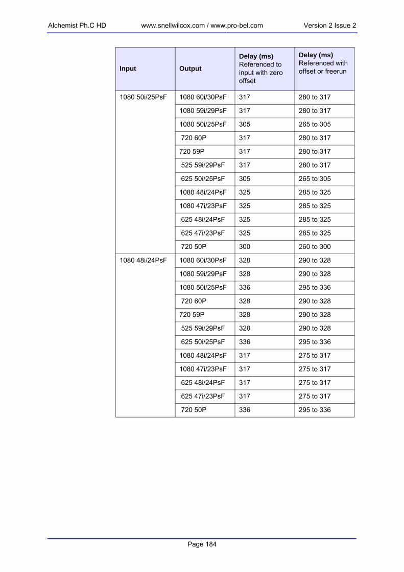
Alchemist Ph.C HD www.snellwilcox.com / www.pro-bel.com Version 2 Issue 2
1080 50i/25PsF 1080 60i/30PsF 317 280 to 317
1080 59i/29PsF 317 280 to 317
1080 50i/25PsF 305 265 to 305
720 60P 317 280 to 317
720 59P 317 280 to 317
525 59i/29PsF 317 280 to 317
625 50i/25PsF 305 265 to 305
1080 48i/24PsF 325 285 to 325
1080 47i/23PsF 325 285 to 325
625 48i/24PsF 325 285 to 325
625 47i/23PsF 325 285 to 325
720 50P 300 260 to 300
1080 48i/24PsF 1080 60i/30PsF 328 290 to 328
1080 59i/29PsF 328 290 to 328
1080 50i/25PsF 336 295 to 336
720 60P 328 290 to 328
720 59P 328 290 to 328
525 59i/29PsF 328 290 to 328
625 50i/25PsF 336 295 to 336
1080 48i/24PsF 317 275 to 317
1080 47i/23PsF 317 275 to 317
625 48i/24PsF 317 275 to 317
625 47i/23PsF 317 275 to 317
720 50P 336 295 to 336
Input Output
Delay (ms)Referenced to input with zero offset
Delay (ms)Referenced with offset or freerun
Page 184

Version 2 Issue 2 www.snellwilcox.com / www.pro-bel.com Alchemist Ph.C HD
1080 47i/23PsF 1080 60i/30PsF 328 290 to 328
1080 59i/29PsF 328 290 to 328
1080 50i/25PsF 336 295 to 336
720 60P 328 290 to 328
720 59P 328 290 to 328
525 59i/29PsF 333 295 to 333
625 50i/25PsF 336 295 to 336
1080 48i/24PsF 317 275 to 317
1080 47i/23PsF 317 275 to 317
625 48i/24PsF 317 275 to 317
625 47i/23PsF 317 275 to 317
720 50P 336 295 to 336
720 60P 1080 60i/30PsF 253 220 to 253
1080 59i/29PsF 253 220 to 253
1080 50i/25PsF 278 245 to 278
720 60P 253 220 to 253
720 59P 253 220 to 253
525 59i/29PsF 253 220 to 253
625 50i/25PsF 278 245 to 278
1080 48i/24PsF 278 245 to 278
1080 47i/23PsF 278 245 to 278
625 48i/24PsF 278 245 to 278
625 47i/23PsF 278 245 to 278
720 50P 273 240 to 273
Input Output
Delay (ms)Referenced to input with zero offset
Delay (ms)Referenced with offset or freerun
Page 185

Alchemist Ph.C HD www.snellwilcox.com / www.pro-bel.com Version 2 Issue 2
720 59P 1080 60i/30PsF 253 220 to 253
1080 59i/29PsF 253 220 to 253
1080 50i/25PsF 278 245 to 278
720 60P 253 220 to 253
720 59P 253 220 to 253
525 59i/29PsF 253 220 to 253
625 50i/25PsF 278 245 to 278
1080 48i/24PsF 278 245 to 278
1080 47i/23PsF 278 245 to 278
625 48i/24PsF 278 245 to 278
625 47i/23PsF 278 245 to 278
720 50P 273 240 to 273
720 50P 1080 60i/30PsF 317 280 to 317
1080 59i/29PsF 317 280 to 317
1080 50i/25PsF 305 265 to 305
720 60P 317 280 to 317
720 59P 317 280 to 317
525 59i/29PsF 317 280 to 317
625 50i/25PsF 305 265 to 305
1080 48i/24PsF 325 285 to 325
1080 47i/23PsF 325 285 to 325
625 48i/24PsF 325 285 to 325
625 47i/23PsF 325 285 to 325
720 50P 300 260 to 300
Input Output
Delay (ms)Referenced to input with zero offset
Delay (ms)Referenced with offset or freerun
Page 186

Version 2 Issue 2 www.snellwilcox.com / www.pro-bel.com Alchemist Ph.C HD
625 50i/25PsF 1080 60i/30PsF 317 280 to 317
1080 59i/29PsF 317 280 to 317
1080 50i/25PsF 305 265 to 305
720 60P 317 280 to 317
720 59P 317 280 to 317
525 59i/29PsF 317 280 to 317
625 50i/25PsF 305 265 to 305
1080 48i/24PsF 325 285 to 325
1080 47i/23PsF 325 285 to 325
625 48i/24PsF 325 285 to 325
625 47i/23PsF 325 285 to 325
720 50P 305 265 to 305
625 48i/24PsF 1080 60i/30PsF 328 290 to 328
1080 59i/29PsF 328 290 to 328
1080 50i/25PsF 336 295 to 336
720 60P 328 290 to 328
720 59P 328 290 to 328
525 59i/29PsF 333 295 to 333
625 50i/25PsF 336 295 to 336
1080 48i/24PsF 317 275 to 317
1080 47i/23PsF 317 275 to 317
625 48i/24PsF 317 275 to 317
625 47i/23PsF 317 275 to 317
720 50P 336 295 to 336
Input Output
Delay (ms)Referenced to input with zero offset
Delay (ms)Referenced with offset or freerun
Page 187

Alchemist Ph.C HD www.snellwilcox.com / www.pro-bel.com Version 2 Issue 2
625 47i/23PsF 1080 60i/30PsF 328 290 to 328
1080 59i/29PsF 328 290 to 328
1080 50i/25PsF 336 295 to 336
720 60P 328 290 to 328
720 59P 328 290 to 328
525 59i/29PsF 333 295 to 333
625 50i/25PsF 336 295 to 336
1080 48i/24PsF 317 275 to 317
1080 47i/23PsF 317 275 to 317
625 48i/24PsF 317 275 to 317
625 47i/23PsF 317 275 to 317
720 50P 336 295 to 336
525 59i/29PsF 1080 60i/30PsF 253 220 to 253
1080 59i/29PsF 253 220 to 253
1080 50i/25PsF 278 245 to 278
720 60P 253 220 to 253
720 59P 253 220 to 253
525 59i/29PsF 253 220 to 253
625 50i/25PsF 278 245 to 278
1080 48i/24PsF 278 245 to 278
1080 47i/23PsF 278 245 to 278
625 48i/24PsF 278 245 to 278
625 47i/23PsF 278 245 to 278
720 50P 278 245 to 278
Input Output
Delay (ms)Referenced to input with zero offset
Delay (ms)Referenced with offset or freerun
Page 188

Version 2 Issue 2 www.snellwilcox.com / www.pro-bel.com Alchemist Ph.C HD
Appendix G: RollTrack Audio Delay Tracking
RollTrack is a feature of RollCall™ (Snell & Wilcox’s proprietary remote control system), that allows devices to communicate across the RollCall network with no direct user intervention.RollTrack Audio Delay Tracking enables Snell & Wilcox RollCall™ compatible audio delay products to track delay introduced by RollCall™ compatible video processing products.The simplest configuration is a single video unit and a single audio delay in a RollCall™ system. The audio delay will have the same delay as through the video path. If the delay changes the audio delay will track.
The next level of configuration is where there are multiple Frame Synchronizers (for example) each connected through RollCall™ to their own tracking Audio Delay. (It is worth stating that the synchronizers and audio delays do not have to be in the same enclosure; the addressing scheme, discussed later, allows for the units to be positioned anywhere in the RollCall™ domain.)The maximum number of video units and audio delays in a RollCall™ system is set by the maximum limit of the number of modules in a RollCall™ network and is currently 3840 on a single network without bridges.The unique identification of the destination unit (a decimal number) for various modules is as follows:
IQD1FSY
IQBADC
RollCall connection
4:2:2
AnalogueAudio
delayed video by 10 ms
delayed audio by 10 ms
Module IDIQBADC 51IQBDAC 52IQBAAD 53IQBDAD 54IQBSYN 89IQBADCD 107
Page 189

Alchemist Ph.C HD www.snellwilcox.com / www.pro-bel.com Version 2 Issue 2
The next level of complexity is a vertical delay cluster where a video unit can have up to eight audio delays tracking - of the same or different types.
From one to eight audio delay products can be connected via RollCall™ to a single frame synchronizer, for example. If the synchronizer delay changes, then however many audio delays are connected will track the delay. The audio delays can also have a manual delay which will be added to the RollTrack delay.The next level of complexity is a horizontal delay cluster where an audio delay can track up to four video units.
The total delay time through the audio delay is then the sum of the individual delays introduced by the video units plus the manual delay of the audio unit. The manual delay can be set to compensate for any fixed propagation delay in the video path or may be set to zero.The next level of complexity is a matrix delay cluster where each audio delay (up to eight) can track up to four video units. This configuration is in effect a four by eight matrix of video units and audio delay units. The total delay time through the
IQD1FSY
IQBADC
IQBAAD
RollCall network connection
4:2:2
AnalogueAudio
AnalogueAudio
delayed video by 10 mschanges to 20 ms
delayed audio by 10 mstracks to 20 ms
delayed audio by 10 mstracks to 20 ms
IQDMSDAΔ1
IQD1FSYΔ2
IQD1FSYΔ3
IQD1FSYΔ4
IQBADCΔm (= manual delay setin the BADC)
Total delay:
ΔΤ = ∑ Δ1−4 + Δm
RollCall network connection
Page 190

Version 2 Issue 2 www.snellwilcox.com / www.pro-bel.com Alchemist Ph.C HD
54
54545454
*54*54*54
audio delay units is then the sum of the individual delays introduced by the video units plus the manual delay of the audio unit.
As any of the delay times change in the video path so will the audio delay time track this delay.A virtual connection is made between from, say, an IQD1FSY to an IQBDAD by:• selecting the Setup... Menu of the IQD1FSY• then selecting the Audio_Delay... Menu• then choosing from Unit_1 to Unit_8• then entering the unique network address of the IQBDAD in the form
nnnn:xx:yy*z*d • where nnnn = network address and in most cases will be 0000(hex); • xx = IQ enclosure address (hex); • yy = slot address of the IQBDAD (hex)• z = the connection (or channel) number (decimal) - see table below.
d = the unique identification of the destination unit (decimal) The ID entered must match the receiving units own ID or else the command will be ignored. If the ID value is set to 00, the receiving unit does not perform an ID match and will always accept the incoming command then selecting the Delay... Menu of the IQBDAD then selecting RollTrackExample of Network Addresses with Channel Numbers and ID Numbers
IQDMSDAΔ1
IQD1FSYΔ2
IQD1FSYΔ3
IQD1FSYΔ4
IQBDAD 1ΔΤ = ∑ Δ1−4 + Δm
RollCall networki
IQBDAD 8ΔΤ = ∑ Δ1−4 + Δm
D1FSY 1 D1FSY 2 D1FSY 3 D1FSY 4Audio delay 1 0000:10:01*14*54
0000:10:01*15*540000:10:01*16*54 0000:10:01*17*
Audio delay 20000:10:03*14*54 0000:10:03*15*54 0000:10:03*16*54 0000:10:03*17*
Audio delay 3 0000:10:05*14*54 0000:10:05*15*54 0000:10:05*16*54 0000:10:05*17*Audio delay 4 0000:10:07*14*54 0000:10:07*15*54 0000:10:07*16*54 0000:10:07*17*Audio delay 5 0000:10:09*14*54 0000:10:09*15*54 0000:10:09*16*54 0000:10:09*17*Audio delay 6 0000:10:0B*14*54 0000:10:0B*15*54 0000:10:0B*16*54 0000:10:0B*17Audio delay 7 0000:10:0D*14*54 0000:10:0D*15*54 0000:10:0D*16*54 0000:10:0D*17Audio delay 8 0000:10:0F*14*54 0000:10:0F*15*54 0000:10:0F*16*54 0000:10:0F*17
Page 191

Alchemist Ph.C HD www.snellwilcox.com / www.pro-bel.com Version 2 Issue 2
The most complex system would be an array of matrix delay clusters
Page 192

Version 2 Issue 2 www.snellwilcox.com / www.pro-bel.com Alchemist Ph.C HD
Page 193

Alchemist Ph.C HD www.snellwilcox.com / www.pro-bel.com Version 2 Issue 2
Page 194

Version 2 Issue 2 www.snellwilcox.com / www.pro-bel.com Alchemist Ph.C HD
Manual Revision RecordDate Version Issue Change Comments
120107 1 1 First issue
101007 1 2 For software version 1.1 New issue
090108 1 3 For software version 1.1.3 New issue
050608 1 4 For software version 2.0 New issue
200808 1 5 For software version 2.1 New issue
220109 2 1 New manual template. Manual updated for software V3.0 (FilmTools).
New version and issue
250309 2 2 Manual updated for software V4.0 (Dolby E)
New issue
Page 195

Alchemist Ph.C HD www.snellwilcox.com / www.pro-bel.com Version 2 Issue 2
Page 196